engineering our navy - dso national laboratories...engineering our navy engineering our navy message...
TRANSCRIPT

“DTC IS THE
SECRET-EDGE
WEAPON OF
THE SAF”
DR NG ENG HEN
MINISTER FOR DEFENCE
ENGINEERINGOUR NAVY

II The opinions and views expressed in this work are the authors’ and do not necessarily reflect the official views of the Ministry of Defence

Foreword
Message
Preface
CHAPTER 1 : Naval Engineers And Naval Systems Engineers – Who Are They and What Do They Do?
CHAPTER 2 : The Anti-Ship Missile
CHAPTER 3 : Beyond the Horizon
CHAPTER 4 : Collaborative Systems – Force Multiplication
CHAPTER 5 : Organisational System-of-Systems – Overcoming the Challenges of Size and Sustainability
CHAPTER 6 : Naval Platforms – Multi-Role and Multi-Dimensional
CHAPTER 7 : The Electromagnetic Battlefield
CHAPTER 8 : The Under-Sea Environment
CHAPTER 9 : The Information Domain
EPILOGUE
ACKNOWLEDGEMENTS
GLOSSARY
INDEX
TABLE OF CONTENTS
1
6
18
36
40
43
66
79
87
94
99
104
107
ENGINEERING OUR NAVY ENGINEERING OUR NAVY
FOREWORD
The journey of Singapore’s Defence Technology Community (DTC) parallels that of the Singapore Armed Forces (SAF) – indeed both were co-dependent and iterative processes which fed off each other’s success. Pioneers in both communities recognised very early on the stark limitations of a small island with no geographical depth and limited manpower. But despite this realisation, they were undaunted and shared a common resolve to mitigate Singapore’s vulnerabilities and constraints, and build a credible SAF through sheer will, commitment and the harnessing of the powers of technology. In Dr Goh Keng Swee’s words, “we have to supplement the SAF’s manpower with new technology, as manpower constraints will always be there. Our dependency should be more on technology than manpower. And we must develop indigenously that technological edge.” As worthy and important as these ideals were, it was an arduous journey for the DTC. With poor standards of general education, let alone engineers or scientists, how could Singapore develop such capabilities?
This book series chronicles the last 50 years of that ascent that begun in 1966. The DTC has indeed come a long way from its humble beginnings and with it, a transformation of the SAF’s capabilities. Today, both the SAF and the DTC are respected professional bodies and the requests from advanced economies to collaborate reflect the standards which we have achieved. Our closely-knit community of defence
engineers and scientists stands at the frontier of technological progress. Indeed the DTC is the secret-edge weapon of the SAF.
As the DTC celebrates its 50th anniversary, we want to thank especially its pioneers who were committed to achieve the unthinkable and were not daunted by severe challenges along the way. Their efforts and beliefs have spawned world class agencies such as DSTA and DSO, and the family of Singapore Technologies (ST) companies.
More hearteningly, the virtuous effects extend into mainstream society too. Today the defence cluster of DSTA, DSO, MINDEF, the SAF and ST employs the largest proportion of scientists and engineers in Singapore – almost one in every 12! It is not an overstatement that these entities have been the main receptacles to maintain the science and technology capabilities in our nation, providing life-long careers in the process.
Beyond defence, the DTC has also positively impacted our society in a variety of ways: in producing mass thermal scanners to combat the 2003 SARS outbreak, in designing and building the iconic Marina Bay Floating Platform to host the National Day Parades and sports events, in breaking new ground and old mindsets when we built the underground storage for munitions, in forming the nucleus to start the MRO (maintenance, repair and overhaul) industries to service airlines in Singapore and globally.
The stories that are told in this book series chronicles should lift the spirits of Singaporeans, old and young. They celebrate what pioneers and successive generations of committed scientists and engineers have accomplished over the years. But they also give hope to our future, as they will serve as reminders during difficult times to overcome challenges and continue to keep Singapore safe and secure for many years to come.
Dr Ng Eng HenMinister for Defence
Singapore

ENGINEERING OUR NAVY ENGINEERING OUR NAVY
MESSAGE
The Defence Technology Community (DTC) has steadily evolved over the last 50 years. We started off as a small, three-man technical department in the Logistics Division in 1966 supporting defence equipment procurement and there was much work to be done. The Army then was largely equipped with second-hand vehicles and surplus equipment left by the British. The Republic of Singapore Navy (RSN) had two boats, one steel and the other wooden. Recognising the need to overcome the immutable challenges of geography and resource constraints facing Singapore, we extended our scope to include conceptualisation, development and upgrade of defence systems. These efforts leverage the force multiplying effects of technology to meet the unique challenges and operational requirements of the Singapore Armed Forces (SAF), beyond what could be had buying off-the-shelf.
This four-book “Engineering Singapore’s Defence – The Early Years” series covers the entire spectrum of the DTC’s work in the land, air and sea domains to deliver cutting-edge technological capabilities to the SAF. It chronicles our 50-year journey and documents the largely unheard stories of our people – their challenges, struggles and triumphs, their resolve and ingenuity, and their persistence in overcoming the odds. These stories include:
• The upgrading of the French-made AMX-13 light tank to the AMX-13 SM1 configuration by the DTC, the Army and ST Engineering, laying the foundation for the design, engineering and production of the Bionix, Bronco and Terrex armoured fighting vehicles for the Army.
• The integration of the RSN’s missile gunboats and missile corvettes which built up the DTC’s confidence to move on to specify and acquire best of breed systems to integrate into new ships like the frigates. It also laid the foundations for ST Engineering’s capabilities to design and build ships for the RSN and some other navies.
• The conversion of old US Navy’s A-4 Skyhawk aircraft into the A-4SU Super Skyhawk for the Republic of Singapore Air Force, building up ST Engineering’s capabilities to undertake further aircraft upgrades such as for the F-5E Tiger fighter aircraft, and to undertake servicing and repair of commercial aircraft.
• The system-of-systems integration efforts to evolve the island air defence system, building on legacy systems left by the British to seamlessly incorporate new weapons, sensors, and indigenously developed command and control systems to extend the range and coverage of Singapore’s air defence umbrella, and the build-up of the DTC as a system-of-systems to deliver cutting-edge capabilities and systems to the SAF, and to meet the technology requirements of the nation.
While not exhaustive, these stories provide us with a glimpse of the “dare-to-do” and enterprising spirit that our DTC personnel and forerunners possess.
There is no end to change and transformation. Singapore and the SAF will continue to face many challenges in the years ahead. However, with the capabilities and expertise developed over the years in its more than 5,000-strong personnel, and its established linkages with
renowned R&D partners locally and around the world, I am confident that the DTC will remain steadfast in delivering the critical technologies and innovative solutions for the SAF and the nation. May the stories in these books inspire our current and future defence engineers and scientists to continue to push boundaries and think creatively to deliver capabilities that will safeguard our sovereignty for the years to come.
Mr Ng Chee KhernPermanent Secretary (Defence Development)
Ministry of Defence, Singapore

ENGINEERING OUR NAVY ENGINEERING OUR NAVY
Well before the turn of the last millennium and before the advent of internet search, if one wanted to learn about the world’s navies it would be usual to turn to Jane’s Fighting Ships — a compendium of the world’s naval forces that was published annually. Leafing through the pages it would be unusual to find many navies with a manpower strength below 5,000 that could boast a balanced range of capabilities. One such anomaly, however, was the Republic of Singapore Navy (RSN). It had a wide range of capabilities, including surface strike, amphibious, mine hunting, underwater warfare and maritime air within an organisation of less than 5,000 people in active service. How could an organisation of this size build and sustain such a range of capabilities and keep it in a high state of readiness?
Engineering Our Navy is our attempt to narrate the development of the RSN from an engineering perspective. It endeavours to show how the application of engineering and systems approaches has provided the means to advance the RSN to what we see today. This is not just a narrative of technology acquisition, but an attempt to narrate the conceptual approach guided by the principles and concepts of systems engineering (or engineering systems; this being considered more appropriate by some prominent institutions such as the Massachusetts Institute of Technology as they take a wider view of engineering that includes other disciplines beyond the traditional fields of hard engineering disciplines).
Systems engineering as applied in the defence and aerospace sectors has resulted in many of the modern technological innovations that we see today, including air and space travel, the Internet, the Global Positioning System and robotics. Systems thinking approaches have also been developed in fields such as biology and the social sciences however. Systems thinking is therefore not confined to the field of engineering, but the combination of systems and engineering approaches has been a powerful conceptual approach to the development of large-scale engineered and human activity systems. This approach (not the hardware) is the force multiplier that underpins the ability of the RSN to attain capabilities not immediately evident by an examination of its constituent parts.
PREFACE
Constraints of Size & Geography Coastal Defence &
Maritime Security
SLOC, HADR, International Peacekeeping
Surface Strike (Over the Horizon)
Multi-dimensional Naval Warfare
Multi-national, International
Specialised Warfare(Submarines, Special forces, Unmanned systems)
Joint Services, Civil- Military, Whole of Government
Surface Strike (Radar horizon)
Specialised Warfare (Mines)
Single Service
Emerging (Counter-terrorism, Cyber)
Create strategic depth and force multiplication by exploiting the time dimension
Force multiplication through technology, high readiness, organisation, sound planning and execution
Lessons from Engineering A Navy
As the Defence Technology Community celebrates its 50th anniversary, this book is dedicated to the defence systems engineers whose efforts and ingenuity have contributed to the Singapore Armed Forces and the RSN of today.
RADM (Ret) Richard LimEditor, Engineering Our Navy
1 ENGINEERING OUR NAVY
Chapter 1 NAVAL ENGINEERS AND NAVAL SYSTEMS ENGINEERS
2ENGINEERING OUR NAVY1
NAVAL ENGINEERS AND NAVAL SYSTEMS ENGINEERS - Who Are They and What Do They Do?
After the Independence of Singapore in 1965, the Royal Malaysian Naval Volunteer Force became the Singapore Naval Volunteer Force. The name was changed to Sea Defence Command in September 1967 and changed again in December 1968 to Maritime Command (MC). MC assumed responsibility to raise naval forces for the defence of Singapore from the sea. On 1st April 1975, MC was re-designated as the Republic of Singapore Navy (RSN) when both the Navy and Air Force were established as separate services in the Singapore Armed Forces (SAF).
During the early build-up of MC, there was a need to establish an engineering support capability as sophisticated naval platforms were being acquired. These included the six patrol craft (PCs) and six missile gunboats (MGBs) that were to be brought into service. Besides being sophisticated ship systems these ships had integrated weapons and sensor systems. Sophisticated search and fire control radars were interfaced with guns and missile systems. For a long time naval weapons were standalone systems mounted on board ships. Ship systems were supported by marine engineers, and weapons systems were supported and maintained by weapon electronics engineers. There was minimal integration between these two domain areas.
The arrival of these new PCs and MGBs required that a systems integration capability be established. Marine engineers and weapons electronics engineers had to work together to integrate and support these sophisticated systems. The PC and MGB programmes had largely involved the construction of the vessels
in Singapore shipyards (although the first of class ships were constructed in overseas yards) and the outfitting, integration and testing of these ships and systems by established international systems integrators supported by our local engineers. These activities were valuable learning opportunities for our fledgling group of naval systems engineers that included both uniformed engineers in the RSN and civilian engineers from the Ministry of Defence (MINDEF). These engineers were specially selected for these roles and included many scholarship holders who had returned after completing their engineering studies both in local and overseas institutions. Important systems integration, testing and evaluation expertise were established during these early years that would subsequently set the stage for more developments in the RSN.
For naval engineers, building and fielding new ships and weapons systems had to, for some time, take second priority to supporting operations though. The fall of Vietnam and the subsequent wars in Indo-china in the 1970s threw the young RSN into a decade of continuous maritime patrols and enforcement operations that took a considerable toll on both people and equipment in the RSN. Training and doctrine development in the use of its sophisticated weapons and systems played second fiddle to the continual grind of day-to-day patrols. The naval engineers had to focus on the challenging tasks of ensuring ships and systems readiness and reliability to meet the demands of prolonged operations. These new ships were not specifically designed for such prolonged operations at slow speeds, and their sophisticated weapons systems were not exactly suited for low-intensity military operations.
However, these trying times in the history of the RSN enabled the development of a different set of skills and expertise in the field of systems engineering – the application of systems engineering knowledge to support operations. This would become a critical
building block in establishing our present capability of keeping the RSN in a constant high state of readiness. Concepts of reliability, availability and maintainability; modelling and prediction of systems and component failures; procurement and stockpiling of critical spares; and the development of lean and efficient base support operations were learnt, practised and improved during these years.
Just as important was the establishment and refinement of the readiness condition (or ‘REDCON’) system that integrated the engineering and supply system with the mission and readiness requirements of the RSN, an end-to-end efficient value chain producing the right level of high readiness operational units to meet mission requirements. This was possibly our first attempt in developing a systems architecture for a high readiness military force production system, although we were not consciously going about it from a systems architecture perspective.
Even as defence policy and budget priorities eventually allowed the RSN to build the capabilities for a balanced navy that would move beyond the capability of seaward defence to the protection of our sea lines of communications, the RSN was limited in looking for good solutions in the developed navies. Unlike the Army and the Air Force, it was extremely difficult to find a suitable platform or weapons system deployed by the developed navies that could suit our needs. Most of the existing multi-role ships were large vessels that were manned by crews of several hundred: a manning concept that was not feasible for a navy with limited manpower resources. Many of their weapons were developed for areas of operations with quite different characteristics compared to the tropical littoral waters of our operating area.
The RSN could only look to cooperating with a limited number of smaller navies that had similar requirements; but was largely
left to its own devices to seek solutions to its unique requirements. This provided both challenges and opportunities for our naval systems engineers and scientists of the defence technology community. The chapters within this book narrate some of the work of our engineers as they mastered and applied the discipline of large-scale systems engineering over the system development life cycle: conceptualisation, architecture and design, development, test and evaluation, and support.
Who were our naval engineers and naval systems engineers? They were a diverse group of people with different backgrounds but with a shared focus on applying engineering and systems thinking in the maritime domain. They included naval architects, marine, mechanical, electrical and electronics engineers (even aeronautical engineers!) from the traditional engineering disciplines; but also people from the sciences (physics, chemistry and biology), information technology, medical sciences, naval operations, the social sciences and management. Their expertise covered both depth of understanding in a specific domain complemented by the ability to work across multiple domains – the T-shaped competency profile.
Chapter One

3 ENGINEERING OUR NAVY
Chapter 1 NAVAL ENGINEERS AND NAVAL SYSTEMS ENGINEERS
ENGINEERING OUR NAVY
Chapter 1 NAVAL ENGINEERS AND NAVAL SYSTEMS ENGINEERS
4
Over the years the contributions of our engineers have been recognised through various Defence Technology Prize (DTP) Awards. The DTP is awarded annually to individuals or teams who have made significant technological contributions to the defence capability of Singapore:
1990 DTP Team AwardThe Missile Corvette Team: Led by Mr Quek Pin Hou and comprising members from Defence Materials Organisation, Defence Science Organisation and the Republic of Singapore Navy
1992 DTP Team AwardThe Naval Electronics System Team: Led by Mr Loh Quek Seng and comprising members from Defence Materials Organisation, Defence Science Organisation and the Republic of Singapore Navy
1995 DTP Team AwardThe Maritime Patrol Aircraft Project Team: Led by Mr Lee Kian Kong and comprising members from Defence Materials Organisation, Defence Science Organisation and Air Logistics Department
1996 DTP Team AwardPatrol Vessel Programme Team: Led by LTC Thomas Vergis and comprising members from Defence Materiel Organisation, Command, Control, Communications and Computer Systems Organisation, Defence Science Organisation and the Republic of Singapore Navy
1998 DTP Team AwardThe Underwater Shock Technology Programme Team: Led by Associate Professor Lam Khin Yong and comprising members from Institute of High Performance Computing, Naval Logistics Department and DSO National Laboratories
2001 DTP Team AwardThe New LST Integrated Project Management Team: Led by Dr Koh Hock Seng and comprising members from Defence Science and Technology Agency, Singapore Technologies Marine, Singapore Technologies Electronics and the Republic of Singapore Navy
2006 DTP Team AwardThe Specialised Marine Craft Team: Defence Science and Technology Agency, DSO National Laboratories and Singapore Technologies Marine
2007 DTP (Engineering Award)The Formidable Class Stealth Frigate Integrated Programme Management Team: Defence Science and Technology Agency, the Republic of Singapore Navy, DSO National Laboratories, Singapore Technologies Electronics and Singapore Technologies Marine
2010 DTP (Engineering Award)The Comprehensive Maritime Awareness Team: Defence Science and Technology Agency, the Republic of Singapore Navy, DSO National Laboratories, Singapore Technologies Electronics
Some of our pioneering naval engineers,
circa early 1970s.
Reminiscences of an Early Defence Technology Community Pioneer – What I remember most about these early days By Mr Ho Jin Yong
What do I remember most? It is not the excitement of weapons systems testing, nor the desperation of trying to conclude a contract in a smoke-filled room. It is about trust − trust in people.
Some parts of a weapons system must be regularly replaced due to their limited shelf life. This would cost lots of money, and therefore approval must be sought from the higher management. In the middle of 1970s, I was asked by James Leo, then Commanding Officer of the Naval Maintenance Base, to prepare a staff paper to the Naval HQ to seek that approval. Writing a staff paper was definitely not my strength as I was a young engineer then. The first draft that went up to James Leo was, as expected, returned with a lot of comments. The second draft suffered the same fate. We met up and discussed, but the third draft was still not good enough. A new draft was written. It went on and on. Remember, those were the days when the only office automation was the typewriter. After many amendments, the draft eventually passed the high standard of James Leo. It was the 14th draft and quickly tabled for Naval HQ’s approval. Nervously waiting outside the conference room, I was called to enter the room when my paper was to be discussed. But
before I could even speak a word, the secretary signalled to me that it had been approved and I could leave. That was my first experience of trust placed in me to produce a perfect staff paper. And that trust was mutual, otherwise it would not have been re-drafted 14 times.
A few years earlier, RSS Sea Dragon had completed its systems integration and testing. It was time to test-fire the Gabriel surface-to-surface missile. On the day of the firing, the sea was rough, but spirits were high. When everything was set, a message was sent to the HQ to inform the Skyvan aircraft to proceed to the firing area. But not long after, a fault developed in the radar system. The engineers and technicians were frantically trying to get it fixed. As the clock ticked away, it was clear that the firing had to be aborted and everyone would be disappointed. The engineer from the radar company then suggested that we cannibalise the whole radar transmitter rack from another MGB nearby. A quick consultation among the naval personnel and the project team was held in the Combat Information Centre. The decision was to go ahead. The rest was history. It was a resounding result with a direct hit. Looking back, I realised that everyone on that day, except the field engineers from the weapon system suppliers, was so young and had never gone through any major exercise before. It was the trust in everyone that made history.
In the 1980s, we moved into the MCV programme. One of the weapons systems encountered some technical issue. It was a major impasse that was beyond the contractor to resolve. We had to raise it to the defence ministry of the contractor’s country. I wrote to the then Second Permanent Secretary, Mr Philip Yeo, for guidance. He called me to his office. After comprehending the situation, he asked me to draft a letter for him to send to his counterpart. The next day, I brought the draft letter to his office. To my utter shock, he simply put his signature down without reading it. While it did not make history, the

ENGINEERING OUR NAVY 65 ENGINEERING OUR NAVY
Chapter 1 NAVAL ENGINEERS AND NAVAL SYSTEMS ENGINEERS
letter did resolve the problem quickly. But more than that, it was trust in people that I most appreciated and fondly remembered.
Our pioneers in their finest, circa mid 1970s.
RADM (Ret) James Leo, then Chief of Navy recalls…
“ We started in two rows of shabby buildings in Pulau Blakang Mati, moving on to Pulau Brani to take over the slightly better facilities vacated by the UK Royal Corp of Transport.
Our engineers provided the requirements for the building of the Brani Naval Base. We took some equipment left by the British forces and set them up in the new Brani workshops. Apart from buying a new brake-dynamometer, the Brani engine test bay was designed, fabricated and set up on our own. Electronic test equipment was basic, and so was the set-up for rewinding of electric motors/alternators. In those days we had few resources and did all sorts of things ourselves. For example, our engineers helped to set up the missile maintenance facilities and performed damage control operations (from the outside). ” “ Our ships’ engines were plagued by recurrent cylinder heads cracking, so our engineers resorted to experiments to coat them with ceramic. This was before they discovered, during metallurgical analysis with
the then Singapore Institute of Standards and Industrial Research, that the casting process was faulty. Engineers also found out that some heat exchanger tubes were of the wrong material.
In the very early days (the 1970s) our PC engines were also plagued by over-speed trips, from those dreadfully unreliable electronic controls overheating in the engine room. The maintenance base actually did the first “Work Improvement Team Scheme or WITS” project (before we had even heard of that term): they designed and fabricated new speed control units, using IC chips (considered “advanced technology” in those days!).
The early days illustrate the enthusiasm, dare (sometimes even foolhardy) and enterprising spirit that drove the young engineers, who “boldly” took on the task for which they had little practical experience. Their contribution to Ops Thunderstorm was unsung, but without them some of the refugee ships would not have been rendered ready to sail when ordered. ”
THE ANTI-SHIP MISSILE
The anti-ship missile brought about a revolution in naval warfare in the late 1960s and 1970s. The Arab-Israeli Wars of 1967 and 1973 demonstrated the lethality of the anti-ship missile in naval surface warfare. Our naval systems engineers were at the forefront of this development. In 1974, RSS Sea Wolf successfully fired a Gabriel surface-to-surface missile, making the RSN the first navy in the region to fire such a missile successfully.
The six MGBs of 185 Squadron armed with the Gabriel anti-ship missile were the principal strike craft of the RSN till the arrival of the MCV in the late 1980s. Gabriel was a semi-active homing missile as compared to others such as the French Exocet anti-ship missile
The Gabriel anti-ship missile, created and manufactured by Israel Aerospace Industries.
Chapter Twowhich had an active seeker head. Exocet had an advantage of range but was more vulnerable to electronic countermeasures (ECM). The fire control radar of the MGB would track the target and give guidance commands to Gabriel. Besides being more resistant to ECM, Gabriel could be directed to another target in flight, giving the MGB greater operational flexibility. Gabriel has a 20km range as compared to Exocet’s 30km.
Our engineers were schooled in the art of systems integration, and test and evaluation during the installation of the various combat systems on board the MGBs. As the MGBs were subsequently upgraded with new capabilities, these engineers upgraded the platform, weapons, sensors and command and control systems to keep the RSN abreast of developments in the offensive and defensive aspects of missile warfare.

Chapter 2 THE ANTI-SHIP MISSILE Chapter 2 THE ANTI-SHIP MISSILE
7 ENGINEERING OUR NAVY ENGINEERING OUR NAVY 8
The Sea Wolf-class MGB was the first vessel in the RSN fleet to be
equipped with an over-the-horizon attack capability.
Given the lethality of anti-ship missiles, significant effort was invested by our engineers in upgrading the defensive capabilities of the MGBs. Electronic sensors were fitted to provide early warning of a missile attack and enable the effective deployment of electronic countermeasures. Modelling and simulation studies allowed the planning for the most effective deployment of such countermeasures. The electronic defences of the MGBs were then evaluated during operational test and evaluation trials at sea. These efforts were supported by scientists and engineers at the then Defence Science Organisation (DSO) (now known as DSO National Laboratories) and led to the accumulation of considerable professional expertise within DSO in electronic warfare.
To improve the detection ranges of electronic sensors, the MGBs were installed with a tall mast to house these sensors. With limited mast space available, the engineers struggled to best position these sensors to ensure minimal electromagnetic interference. An important
lesson learnt was that these sophisticated electronic sensors also had to be installed with lightning protection systems.
As military aircraft became more sophisticated and could deploy smart weapons, the defence against airborne attacks became a challenge that had to be grappled with. The Falklands War in 1982 showed just how vulnerable ships were to airborne attacks, especially when smart weapons such as laser-guided bombs and anti-ship missiles were deployed from air platforms.
Sometime in the 1990s, the RSN was challenged to improve the accuracy of its anti-air gunnery capability. The performance of its anti-air towed target shooting was then less than satisfactory, especially when the target was a slow-moving sleeve target travelling on a steady course. Naval engineers worked with shipboard crews to improve the overall system level performance of the MGB’s anti-air capability. Through extensive system test and evaluation, the sensor-shooter loop was
enhanced so much so that the MGBs regularly shot down the sleeve targets during anti-air towed target gunnery exercises.
As airborne weapons became even more sophisticated eventually, the guns on board the MGBs proved inadequate and the 40mm aft gun was replaced by the Mistral anti-air missile.
The Simbad missile defence
system, as mounted on the Sea Wolf-class
missile gunboats.
Throughout the continual upgrades of the MGBs to fulfil their role as the principal strike craft of the RSN, naval platform engineers had to upgrade the MGB hull and platform systems to carry the increased load of equipment. Ship stability studies including damage-controlled conditions were carried out extensively to ensure that these ships continued to be effective platforms to support their improved capabilities. As more compartment spaces were used for electronic systems, a major drawback was the loss of habitability for MGB crews. However, one upgrade that the crew appreciated was the installation of reverse osmosis plants, which provided adequate freshwater for long deployments. The MGB could be described as a 45m pocket battleship given the extensive upgrades and equipment installed.
With the extensive experience accumulated in the integration, test and evaluation of weapons and platform systems, our planners and engineers built up expertise
in the design and construction of naval surface strike platforms as well as the integration of combat systems in these ships. This led to the next phase whereby the RSN was sufficiently confident to design and specify its next generation surface strike craft. Unlike many small navies that had to acquire their ships and combat systems off-the-shelf from the established defence contractors, the RSN and defence engineers were confident enough in their own expertise to specify and acquire the best systems, and to integrate these into existing and new ships for the RSN.
With the advent of sophisticated weapons that were guided and controlled using electromagnetic waves (especially radar), naval combat moved away from fighting within the visual horizon to the coverage of the radar horizon. Initially, platforms (ships and aircraft) were within radar coverage of each other to engage in combat. Subsequently, given the prevalence of guided weapons, platforms could stay beyond the radar horizon, launching guided weapons to seek out and attack their intended targets autonomously. A revolution in naval warfare took place with revolutionary attack and defence techniques enabled by sophisticated technology. Modelling and simulation, and operational analysis became mandatory to understand and operate effectively in complex scenarios involving one-on-one and many-on-many combat encounter situations. For example, the optimal types and number of gun ammunition and missiles on board ships were computed through such studies.
Two main insights were derived from the rigorous modelling and simulation studies as well as by exercises in the Tactical Training Centre. The first was that our missile craft had to be able to work with each other in a coordinated fashion in combat scenarios against an adversary force with anti-ship missiles. The second was that battles had to be fought beyond the radar horizon.

Chapter 2 THE ANTI-SHIP MISSILE Chapter 2 THE ANTI-SHIP MISSILE
9 ENGINEERING OUR NAVY ENGINEERING OUR NAVY 10
Compact and agile, the 45m Sea Wolf-class
vessels were kept relevant during their
years of service through a slew of weapons
and systems upgrades.
An account of the Navy’s first major Systems Integration Management for the MGB (1970 – 1975) By Mr Quek Pin Hou
How I Got Involved at the Start of the Project
After my studies at the University of Western Australia in Electrical Engineering under a Colombo Plan Scholarship, I was initially posted to Radio and Television Singapore (RTS) as a broadcasting engineer. One fine day, around June 1970, I received a message from Dr Goh Keng Swee’s office that he wanted to see me about possible new postings. I recall at the interview that he asked me about my work at RTS and my interests. I told him that I would prefer to do some advanced technical work before considering management openings. Control systems and communications were my areas of interest. At one point, he commented that the technical assignments in RTS did not appear to offer me sufficient scope. From the discussion, I had the impression that he was looking to field fresh scholarship engineers to certain new assignments.
In early September 1970, a posting order came to RTS that I was to report to the Acting Second Permanent Secretary, Mr JYM Pillay for an interview. Coming to the same interview were two Public Works Department engineers, Mr Lim Siong Guan and Mr Tang CC. After the interview, the three of us were asked to comment on and estimate the cost of the Order of Battle (or ‘ORBAT’), the SAF’s build-up plan. We worked on it for about one month. We had great difficulties as we had little knowledge of defence and military terms. This gave us a chance to visit and talk to the various heads and senior officers at the Upper Barracks at Pearl’s Hill. After nearly one month, we managed to put something
together − whatever little we could muster and compute from the “guesstimates” and explanations we could gather from the various senior officers at Pearl’s Hill, plus our common technical sense as young engineers. Some of the people we talked to turned out to be quite well-known figures in subsequent years − names like Mr James Aeria, LG (Ret) Winston Choo, Prof Lui Pao Chuen, Mr Philip Yeo, Mr Chew Bak Koon and Mr Ong Kah Kok.
At another interview with the Acting Second Permanent Secretary after the study, he mentioned the MGB systems integration for its complex suite of weapons systems, especially the integration between the fire control radar and the Gabriel ship-to-ship missile. MINDEF had hired a US system consultant, Littons Scientific Support Team, to engineer and manage the MGB project.
I liked the prospect of looking into high-tech interfaces between the fire control radar and the radar guided missile, the fire control gunnery interfaces, and the chance to play with X band search and fire control radars. That year was immediately after the 1969 Apollo moon landing space programme, which fascinated me very much as an engineer. I imagined then that playing around with radar, missile and gunnery control would be our version of a mini-Apollo project – something within our reach and would be highly useful for our Navy, for me as a job and for my own curiosity.
Mr Pillay obviously could sense the project was a good match for me. From MINDEF’s angle, he needed then to send in a few good local engineers to understudy Littons as the initial Littons contract was for only two years, with an option for another year so as not to be permanently reliant on Littons. He mentioned something to the effect that we had to learn the trade quickly, and be prepared to take over from Littons when their contract expired.
To a freshly qualified scholarship engineer,
that appeared to be a highly motivating adventure – there was challenging and interesting technical work to explore and work on, very high value knowledge and skills to master, and a definite chance to take over from Littons when their contract expired.
Learning about the Signaal WM28 Fire Control Radar and Gabriel Missile
It was sometime in late October 1970 when I went to Littons’ office located on the upper most floor of an HDB apartment at the highest point of Pearl’s Hill. It was originally a resident quarter for police constables. The topmost floor had been vacated to house the Littons team. As the General Manager (GM) Mr Topham was away with Mr Cheong Quee Wah on an overseas assignment, I met the Deputy GM Mr Red Morrow. Red welcomed me and was happy that I had the background in radar and missile work, after I told him I studied control system, electronics and communications. I then met Mr Ed Clifford and his fire control radar team.
I had expected to be able to see some high-tech equipment, but was told that the equipment was only on order, and I would not be able to see it for at least another two years. When I asked for the equipment specifications or manuals, I learnt that they were also not available except for the summary specifications in the fire control system contract signed with Hollandse Signaalapparaten (HSA). They, however, had a copy of a manual for an earlier version of fire control radar system WM22, and the simpler surface gun fire control radar WM26.
I spent the next few weeks reading through these two manuals. I learnt that the RSN’s first sophisticated fire control radar system, the Signaal WM28, was to be an upgraded version of the WM22, to be modified to interface and control the Gabriel missile.
The WM22 and WM26 manuals turned out to

Chapter 2 THE ANTI-SHIP MISSILE Chapter 2 THE ANTI-SHIP MISSILE
11 ENGINEERING OUR NAVY ENGINEERING OUR NAVY 12
be fascinating reading materials. In the next few weeks, I read up from these the basics of Signaal search and tracking radars, the workings of the search and tracking radar, how air and surface targets were detected and tracked by a specialised digital computer. I enjoyed reading the technical manuals as they were practical applications of my theoretical studies on radar, electronic, and control systems just a year before. I also got hold of the technical description of the Gabriel missile from the neighbouring missile team. We then spent some time going through how the fire control radar was supposed to control the missile in flight, and what and how the contractors were supposed to do or improve on.
The First Major Systems Integration Conference
In mid 1970s, before I came into the picture, MINDEF/RSN had already decided on the Signaal fire control radar, probably because a surface gunnery fire control radar, the WM26, had already been ordered and would soon be delivered on three gunnery PC by end 1970. Signaal WM28 radar would have been a natural choice. Signaal is the military version of Phillips, one of the most well-known electronic brands then. The MGBs and PCs would then have the same brand of radars, with commonalities in technicalities, training and support.
Littons had earlier made a ship-to-ship missile selection study. The study report pointed to the Israeli Gabriel missile as being most suitable for the RSN’s operational requirements. The fire control radar and the missile contracts were already signed before I joined the team. The two contracts were also signed with a rather big uncertainty on the technical specifications on how the radar would talk to and control the missile, and how the missile would respond to the radar. In 1970, this was rather high-tech, and a first time for MINDEF. Other than the consultants and contractors,
no local officers had any real experience or working knowledge on these subjects.
While I had just read up on the radar and missiles, I was told the first systems integration conference would be held in Singapore. Integration between all systems and with the ship would be presented and defined. Among these, the most important missile/radar interface technical integration would be presented and defined. It was about end November to early December 1970.
The venue was to be the conference room in the Singapore Command and Staff College (SCSC) at Fort Canning. What an interesting historic site! Part of the reason was that SCSC had a large air-conditioned conference room. Large conference rooms were rare then and an air-conditioned one was even more so. That was why we had to travel to the Fort Canning SCSC conference room.
Radar and Missile Control Interface
During the missile/radar interface conference, Israel Aircraft Industries (IAI, now known as Israel Aerospace Industries) presented the principal design and interface requirements of the Gabriel missile, while HSA presented the principal performance and specifications of the search and tracking radar which would interface and control the Gabriel missile in flight. Among other things, IAI stressed that the technical design and parameters of the missile could be varied, as the missile had to remain identical in all respects with the Israeli Navy’s own missiles and also to ensure parts availability and interchangeability.
It became clear at the conference that three major aspects were incompatible between the HSA radar and the Gabriel missile:
• The radar had only three frequencies while the missile frequency was variable and not limited in number
• The frequency stability of the radar could
not meet the missile’s requirement• The radar’s azimuth detection voltage
gradient had yet to be defined, and it was uncertain whether it could meet missile guidance requirements
There was quite a long discussion on the frequency issue for both the radar and the missile. From the bandwidth specification and channel separation requirement of the missile, I pointed out to the meeting that the system could have more than 10 frequencies. In fact, the system could have many sets of 10 frequencies at different times. This key finding had a very profound impact on the final redesign of the radar hardware and number of frequency channels for the radar-missile radiofrequency (RF) interface control.
To meet missile requirements, the radar transmitter was redesigned with crystal control with 10 frequency channels. Two more sets of 10 frequencies were made available by way of interchangeable modules so that the ships could change to different frequency sets in different operational situations, such as during periods of tension or war time.
The meeting also resolved the following:
• IAI to define precisely the frequency stability, bandwidth, channel separation, signal-to-noise ratio, and other relevant RF and technical control specifications to HSA
• All above requirements to be reviewed and finalised with the Singapore project team and HSA to confirm their ability to meet the requirements
• HSA to draw up preliminary interface specifications and implementation design, and submit the redesign proposal to the Singapore project team within three months
The redesign of the WM28 tracking radar to meet Gabriel missile technical requirements entailed a significant cost increase and a
four-month schedule extension as claimed by HSA. As the equipment contract was signed without clear specifications for major interface definition, and without contractual provisions for such interface changes, cost and schedule would be at risk. This was something overlooked at the equipment contracting stage, and a key point noted by the project team for future dealings.
Littons helped to negotiate the cost impact to a reasonable level that was deemed acceptable to MINDEF. The bonus was nevertheless that the fire control radar was much improved with better performance, and frequency availability much increased from three to 30 channels. The schedule impact was subsequently minimised by expediting the final packaging and shipping process to Singapore. Transporting the first system by airfreight instead of seafreight was offered by the supplier at their cost. In addition, by interchanging the order of shipboard installation between the missile system and the fire control system, the final nett impact on overall programme schedule was reduced to about two weeks from the original four months.
Systems Integration Engineering Programme Management and Formation of Systems Integration Management Team
Apart from the ship platform and its attendant ship support systems, other major systems to be interfaced and managed included the forward main gun, the aft gun, the search radar, fire control tracking radar, the optical director, the rotating triple launcher and fixed launchers for the ship-to-ship missile, the missiles in their launching boxes, the Identification Friend or Foe (IFF) system, navigational radar, anemometer and radio comms systems in high frequency, very high frequency and ultra-high frequency. In the course of the following year, which was 1971, different system teams of Littons with MINDEF counterparts would work

Chapter 2 THE ANTI-SHIP MISSILE Chapter 2 THE ANTI-SHIP MISSILE
13 ENGINEERING OUR NAVY ENGINEERING OUR NAVY 14
through with the respective interfacing suppliers to vet and finalise the respective interface specifications and installation control documents. The MINDEF counterparts then consisted of six officers initially with Mr Cheong Quee Wah as the project director, Mr Lim Ming Seong and Mr Teo Kim Siak on ship systems, Mr Wong Kok Seng and Mr Chan Chee Hon on missile system, and myself on fire control radar and the IFF System. Mr Steven Chen joined a little later to work on logistics support and training, making the team a total of seven engineers. By the end of 1971 and early 1972, all these had been defined and finalised, thus allowing all system suppliers to complete system production according to schedule.
By early 1972, the MINDEF project personnel realised the need to form a more permanent team out of the initial seven officers and to have a more permanent structure for their career advancement, with the ability to take over Littons’ work when their contract expired in another one to two years. It was also necessary to expand the size of the team of engineers to include some technical support personnel and administrative support personnel. Mr Cheong Quee Wah and I worked on the structure of the organisation. The System Integration Management Team (or ‘SIMT’) was formed in mid 1972 with Mr Cheong Quee Wah as the project director, and myself and Mr Lim Ming Seong as the branch heads for Weapon Electronic Systems, and Ship and Support Systems, respectively. The total engineer strength was increased to 13.
The above is just a highly simplified description of the tasks. Detailed engineering programme management work progressed throughout 1971 and 1972 till various system acceptance tests and deliveries began in late 1972, which continued into 1973 and 1974 for the six platforms and shipboard systems in serial production.
Planning and management for Installation, Check-out, Integration and Testing
The acronym ICIT, which stands for ‘installation, check-out, integration and testing’ for the MGB project, sounded similar to the brand of paint ‘ICI’ when it was first coined by Littons. ICIT activities for the six MGBs were carried out for the first time, and the scale and duration was quite unprecedented for the RSN − for that matter, for MINDEF and the SAF then. First, it involved the most advanced missile boats for Singapore and in the region, and second it entailed major trials with radar, missiles, air and sea targets, over an extended period of time. Third, it was a major project for the RSN and MINDEF costing more than S$150 million.
Littons initiated the planning for ICIT sometime in 1972, headed by Littons’ Director of Engineering Mr Dick King. Sometime later, I was assigned to assist Dick in the execution of many of the detailed tasks. The whole task entailed the drawing up of the installation, check out, integration and weapons systems installation, testing, sequencing, harbour and sea trial schedules. It also involved supporting resources requirement for all the weapons systems and shipboard systems to be carried out in Singapore Shipbuilding and Engineering (SSE, present day Singapore Technologies Marine Ltd (ST Marine)). For illustration, resources planning and provision would include the following:
• Local and factory trained manpower• Skilled and unskilled labour to carry out
installation • Equipment testing• Office and wharf side berthing facilities• Utilities and air-conditioning• Provision of general test and support
equipment• System equipment spares support• Support ship and aircraft for equipment
testing
• Air and sea targets for sea and air gunnery and missile firing trials
• Booking of test ranges for air and sea trials, support ships and aircraft as well as spectator ships and aircraft
The planning, provisioning, and preparation took many months, followed by a full briefing to the Commander of Maritime Command (now known as Chief of Navy) and his principal staff, the MINDEF project team and other relevant Ministry officials. At the same meeting, I was also appointed the ICIT Monitoring Representative for MINDEF in February 1973, with the authority to represent MINDEF/RSN and to monitor and oversee all activities by Littons and all weapons system contractors. In addition, I was to plan and manage all aspects of MINDEF/RSN support resources, ICIT project finance and more.
Highlights of Special ICIT Programme Activities
The ICIT programme for the first MGB RSS Sea Wolf began in early March 1973. It was originally planned to be completed by January 1974 with the final missile firing trial. However, Littons had not fully anticipated the impact of bad weather and high sea states at the end of the year due to the monsoon season. The weather and sea state conditions in December 1973 and January 1974 were so severe that testing and target towing and instrumentation at sea were highly dangerous and impractical. The RSS Sea Wolf’s missile firing test was postponed to early March 1974.
The most critical system interface between the WM28 fire control radar and the Gabriel missile system involved the RF interface when the missile was in flight in the beam rider mode and the semi-active homing mode. Immediately after the missile launch, there was also an optical gathering phase. While the missile was being viewed in the WM28’s Optical Director, RF guidance signal had to be sent via the radar signal to steer the missile
manually into the centre of the radar beam.
Specific tests both in the shipyard and out at sea had to be conducted to verify the RF closed-loop functioning between the radar and the missile transponder. Bearing measurements of the radar for the differential bearing angle between the target echo and missile transponder video pulse also had to be carefully measured and calibrated. This differential bearing was the well-known Delta B measurement and calibration. This series of testing and calibration involved real-time microwave frequency RF transmit/receive measurement and calibration in the shipyard and later in actual sea conditions. It represented a rather advanced level of radar RF transmission/reception and missile guidance control signal measurement and testing conducted for the first time in Singapore then.
The static field measurement done in the shipyard was by way of a measurement T Bar erected at the roof top of the SSE administration building. Feed horns simulating the target echo and missiles transponder signals, with precisely known bearing differential angles between them, enabled precise delta bearing calibration in static environment.
This was subsequently repeated at sea using a light house as a target, and RSS Panglima carrying the missile transponder and feed horn to simulate missile in-flight. RSS Panglima was to criss-cross the line of sight to the target, thus enabling Delta B measurement to be reconfirmed at sea.
Below are some other special findings or points of interest in the RSS Sea Wolf ICIT activities:
• Weapon seat tilt-setting on board ship was traditionally done by an analogue polar plot method. With the advent of high precision digital pocket calculator, the HP35 in 1973, numerical calculation became possible on-the-fly in field work.

Chapter 2 THE ANTI-SHIP MISSILE Chapter 2 THE ANTI-SHIP MISSILE
15 ENGINEERING OUR NAVY ENGINEERING OUR NAVY 16
I worked out the analytical formulae for the tilt-setting geometry. Shipyard technicians could then work out high precision calculations in the field with the HP35 for precision tilt-setting milli-radian calculations and adjustments. This method was much more precise and much faster than using traditional polar plots.
• An Instrumentation Control Unit (ICU) was developed to collect and collate all signals and data systematically to be measured and recorded. The ICU was highly helpful in the measurement and calibration of critical signals in missile and target tracking and firing trials, and to facilitate their recording and compilation for analysis and record keeping. It was to be used subsequently for many weapon firing trials for numerous years in the MGB fleet.
• X band and L band signals were well known to suffer from significant multipath propagation fading near sea surface. This was surprisingly overlooked by the radar, missile and IFF suppliers. In the case of the radar missile transmission and bearing measurement testing, the contractors happened to be doing measurements at a range very near to the multipath fading region for the X band missile signal. The result was very low signal and very high noise. A few sea trials ended with unusable results. I did a range and antenna height calculation using the HP35 calculator and concluded that the trial range was near the fading range. After convincing the contractors, measurement was re-done at an unaffected range. Good results were quickly obtained and systems rapidly calibrated. This finding was also critical in noting the fading regions and characteristics of the missile tracking and guidance signals which should be avoided in the testing and operational use of the missile.
• IFF L band signal at the specific heights applicable in shipboard use also suffered
from significant multipath fading and signal attenuation. The realisation and calculation of the impact of this phenomenon resulted in the modification to the sensitivity time control function of the IFF transceiver. It was also established that multipath fading at L band caused significant signal attenuation. To compensate for this loss, the shipboard cables had to be changed to ultra low loss type. I was able to show that the IFF supplier (Cossor Electronics) overlooked this effect in the system specifications and cable specifications. Cossor finally agreed to absorb the modification and cable replacement costs.
Completion of RSS Sea Wolf and MGB ICIT Programme
After completing all the installation and equipment check-out works followed by preparatory testing and calibrations, RSS Sea Wolf was ready for surface and air gunnery trials by September/October 1973. These were successfully completed. By December 1973, RSS Sea Wolf was ready for the final missile firing trial. A special ship target was constructed, which would be used for many subsequent navy firing trials. It was named the Jolly Roger by Littons. Unfortunately, just as we were ready for rehearsal and final firing trial round about December 1973 to January 1974, sea conditions at the South China Sea firing range turned very adverse. Sea state conditions of up to 5 were encountered for a few rehearsal and firing runs. The bad weather conditions severely hampered the filming and recording instrumentations, the safety of observation ship and aircraft filming operations, as well as civilian technical personnel’s work to support the firing trial. It was decided then to postpone the trial to March 1974, when weather conditions were expected to be more favourable.
RSS Sea Wolf successfully fired two Gabriel missiles which scored direct hits on the
target barge in early March 1974, thus successfully marking the completion of the ICIT programme for the first MGB.
The second to sixth ship programmes proceeded as planned behind the RSS Sea Wolf’s schedule. With the experience gained from RSS Sea Wolf, the ICIT of the subsequent ships were able to avoid many of the difficulties encountered. The second ship, RSS Sea Dragon, completed its missile firing in September 1974. The subsequent ship programmes were spaced out at two to three-month intervals, with the sixth MGB, the RSS Sea Scorpion, completing its ICIT trials in August 1975.
Milestones of the RSN’s MGB
Operationalisation Timeline
1972 — Arrival of first two ships, RSS Sea Wolf and RSS Sea Lion in Singapore.
1974 — The remaining four ships of the squadron, RSS Sea Dragon, RSS Sea Tiger, RSS Sea Hawk and RSS Sea Scorpion were built on the same design and delivered.
22nd January 1975 — RSS Sea Wolf, RSS Sea Lion and RSS Sea Dragon were commissioned.
29th February 1976 — RSS Sea Tiger, RSS Sea Hawk and RSS Sea Scorpion were commissioned. All the six ships were commissioned by then Minister for Defence, Dr Goh Keng Swee.
Key Milestones
31st January 1974 — RSS Sea Hawk, together with other RSN ships and the Marine Police boats surrounded the Laju ferry which was hijacked by four armed terrorists, and successfully prevented them from escaping.
1974 — The RSN became the first navy in the region to fire an anti-ship missile successfully, when RSS Sea Wolf fired the Gabriel surface-to-surface missile. This marked the RSN’s entry into the missile age.
2nd May 1975 — Operation Thunderstorm was activated as a result of the large exodus of Vietnamese people due to the success of the North Vietnamese Communist group. The MGBs were activated to assist in the operation. Despite logistics and manpower challenges, the MGBs contributed significantly to the success of the operation.

Chapter 2 THE ANTI-SHIP MISSILE
17 ENGINEERING OUR NAVY ENGINEERING OUR NAVY 18
1976 — MGB participated in first foreign exercise - Ex EAGLE. Since then, the MGBs were also involved in various other bilateral and multilaterals exercises such as Ex MALAPURA (Malaysia), Ex PELICAN (Brunei), Ex SINGSIAM (Thailand), Ex STARFISH, Ex FLYING FISH and Ex BERSAMA PADU (FPDA countries), SIMBEX (India), Ex SINGAROO (Australia) and Ex CARAT (USA).
1986 to 1988 — The MGBs were upgraded with the long-range Harpoon anti-ship missile. This missile, with an over-the-horizon firing range of over 90km, enhanced the ships’ strike capability and complemented the existing Gabriel missile, giving the ship wider versatility in surface-to-surface combat.
1990 — MGBs participated in the Presidential Sea Review, National Day celebration.
June 1994 — MGBs were upgraded with the Mistral surface-to-air missiles to replace the Bofors 40mm gun. The twin-missile system improved the ships’ ability to defend themselves against enemy aircraft.
July 1994 — The Mistral surface-to-air missile was successfully fired by the MGB.
Throughout their operational service, the MGBs were involved in numerous operations at sea and exercises. Over 5,600 men and women have served on board the MGBs, including Deputy Prime Minister and Coordinating Minister for National Security RADM (NS) Teo Chee Hean, and ex-Minister for Transport RADM (NS) Lui Tuck Yew.
As a testament to the MGBs’ combat readiness, operational proficiency and administrative excellence, the MGBs won the Best Ship award five years in a row from 1986 to 1991. They also clinched Best Ship for a total of 11 years.
BEYOND THE HORIZON
An RSN recruitment video in the late 1980s had a tagline: “Nowadays battles are fought without seeing the enemy – We have the technology!” This short statement represented a significant development in military systems engineering in the Navy.
The naval ship is a platform within which the crew and mission equipment can be housed, supported and protected. It represents a hard system boundary that encapsulates a self-contained collection of combat systems. Within this system boundary it would be easier for the system elements to be optimised collectively in a given real estate. A consistently high level of mission performance could be designed and controlled within the platform. Adverse influences from the external environment affecting mission performance could be mitigated as the platform serves as a shield. Accurate firepower could be projected and controlled from sensor and guidance systems within the platform. This works well so long as combat is conducted within the range of shipboard sensors and control systems.
As combat began to be waged at increasingly longer distances well beyond the radar horizon, system engineers found that they had to deal with achieving consistent, reliable and effective performance of a family of platform based systems. The system boundary of this enlarged system (of systems) was no longer a hard and finite boundary but a shifting one as the platform systems themselves manoeuvre. Linkages between platforms were open to interference from the environment as well as deliberate disruption by enemy action. Traditional systems engineering had to move on to System-of-Systems (SoS) engineering. Information warfare became a critical domain of expertise as information networks that were hitherto operating along protected “internal lines” within a platform now had
to traverse along “external lines” through the environment.
In order to remain relevant in this new order of modern warfare, the RSN acquired the long-range Harpoon missile. The MGB had some of their short range Gabriel missiles replaced with Harpoon missiles. The MCV that were acquired to augment the MGBs were also armed with the Harpoon missiles. In order to exploit the long range of the Harpoon missiles, our engineers and planners began to take steps to link naval platforms with secure digital communications and data links. In addition, the Republic of Singapore Air Force (RSAF) Skyvans were also fitted with these capabilities to provide long-range over-the-horizon targeting.
“But the Navy should accept that nothing worthwhile is easy. Over the next few years as more efforts are put in to improve the quality and combat efficiency of the Navy, you will find that your intellectual capacity, logical thinking, initiative, and originality will be taxed to the maximum. Only those with superior intelligence can define the different scenarios, devise various alternative strategies, and evolve suitable tactics and counter measures to meet a wide range of assumed or possible situations under which RSN will have to fight to defend Singapore. The tactics so evolved will have to be tried, tested, practised, and exercised by RSN ships, commanders, and men so that when the emergency comes they are ready.”
Excerpt from address by the Minister for Defence, Mr Howe Yoon Chong, at the commissioning ceremony of the coastal patrol craft at Pulau Brani Naval Base on Tuesday, 20th October 1981
Chapter ThreeWith the decommissioning of the MGBs, the new Formidable-class stealth frigates made their way into 185 Squadron.

19 ENGINEERING OUR NAVY ENGINEERING OUR NAVY 20
Chapter 3 BEYOND THE HORIZON Chapter 3 BEYOND THE HORIZON
Victory-class MCV
The Victory-class MCVs were commissioned in 1990 and 1991 and are equipped to deal with air, surface and underwater threats. They are the backbone of the RSN’s strike capability and provide seaward defence and protection of Singapore’s vital sea lines of communications.
• Length 62 meters
• Beam 8.5 meters
• Displacement 530 tonnes
• Speed In excess of 30 knots
• Range 2,000 nautical miles
• Crew 46
• WeaponsHARPOON anti-ship missiles, 76 mm OTO Melara Super Rapid Gun, Barak anti-air missiles
Article credit: MINDEF
ScanEagle Unmanned Aerial Vehicle (UAV)
The ScanEagle UAV system was acquired as part of the missile corvette’s upgrade programme to give it an organic surveillance capability. The ScanEagle UAV is made up of four components: the Launcher, the UAV, the Skyhook, and the Control Station.
• Length 1.2 meters
• Wingspan 3.1 meters
• Speed About 53 – 55 knots
Article credit: MINDEF
Several initiatives were embarked upon to network our combat platforms (both sea and air). Lessons learnt with the Skyvans were implemented in the maritime patrol aircraft project. The MCVs were upgraded to work with the RSAF E2-C aircraft. In addition, our planners and engineers began to look for solutions using autonomous and semi-autonomous aircraft that could be deployed and controlled from our naval ships. Our naval architects had made design provisions for our MCVs to deploy unmanned rotary
board RSS Valour was able to detect and track the target and launch the Barak missile, intercepting the target at a range of about six kilometers.
The successful firing demonstrates the effectiveness of the Barak missile point defence system. The Barak missile, together with the MCV’s 76mm OTO Melara Super Rapid gun and ECM equipment, provide the RSN MCVs with a comprehensive capability to counter airborne threats such as sea-skimming missiles and low flying aircraft.
The Barak missile system was acquired by the Navy in 1996, and was fitted on board all six RSN MCVs. Armed with eight Harpoon missile, six Whitehead anti-submarine torpedoes and a sophisticated Electronic Warfare (EW) suite, the MCV is fully capable of carrying out multi-dimensional maritime operations to contribute to fulfilling the RSN’s missions of providing for Singapore’s seaward defence and protecting Singapore’s Sea Lines of Communications.
The RSN conducts regular live firing exercises as well as rigorous t ra in ing programmes under realistic conditions to hone the proficiency and professionalism of its personnel as well as to ensure that its equipment is always at the highest state of operational readiness. Such exercises include successful Harpoon missile and Mistral Surface-to-Air missile firings conducted earlier in the year.
Article credit: MINDEF
aircraft although these provisions were not activated as other solutions were found to be more suitable. One challenge then was the extremely low reliability (measured in mean time between failures) of such rotary aircraft systems. The MCVs were eventually equipped with an organic surveillance capability when the ScanEagle UAV system was integrated for operations. This represented an important development in their over-the-horizon surveillance and targeting capabilities.
As naval guided weapons became even smarter, with many having multiple terminal guidance sensors and sophisticated electronic counter-countermeasures, the defence against such weapons required moving beyond soft-kill electronic defences to hard-kill capabilities. Our engineers participated in the development of an anti-missile system suitable for our small ships and unique operating environment. Our naval architects had made provisions in the design of the MCVs for the subsequent retrofitting of a hard-kill capability. Upon successful development, the MCVs were fitted with the Barak anti-missile system. The development of the Barak was one of the earliest collaborative development projects embarked upon by our scientists and engineers, starting from a theoretical concept.
Singapore Navy’s Anti-Missile Missile Scores Direct Hit
The RSN successfully carried out the first firing of its Barak anti-missile missile during a live firing exercise conducted in the South China Sea yesterday, 10th September 1997. Launched from RSS VALOUR, a MCV, the Barak (meaning "Lightning") missile scored a direct hit against an airborne target simulating a modern anti-ship missile both in terms of size and speed. The fully automated Barak missile fire control system on
21 ENGINEERING OUR NAVY
Chapter 3 BEYOND THE HORIZON
ENGINEERING OUR NAVY 22
Chapter 3 BEYOND THE HORIZON
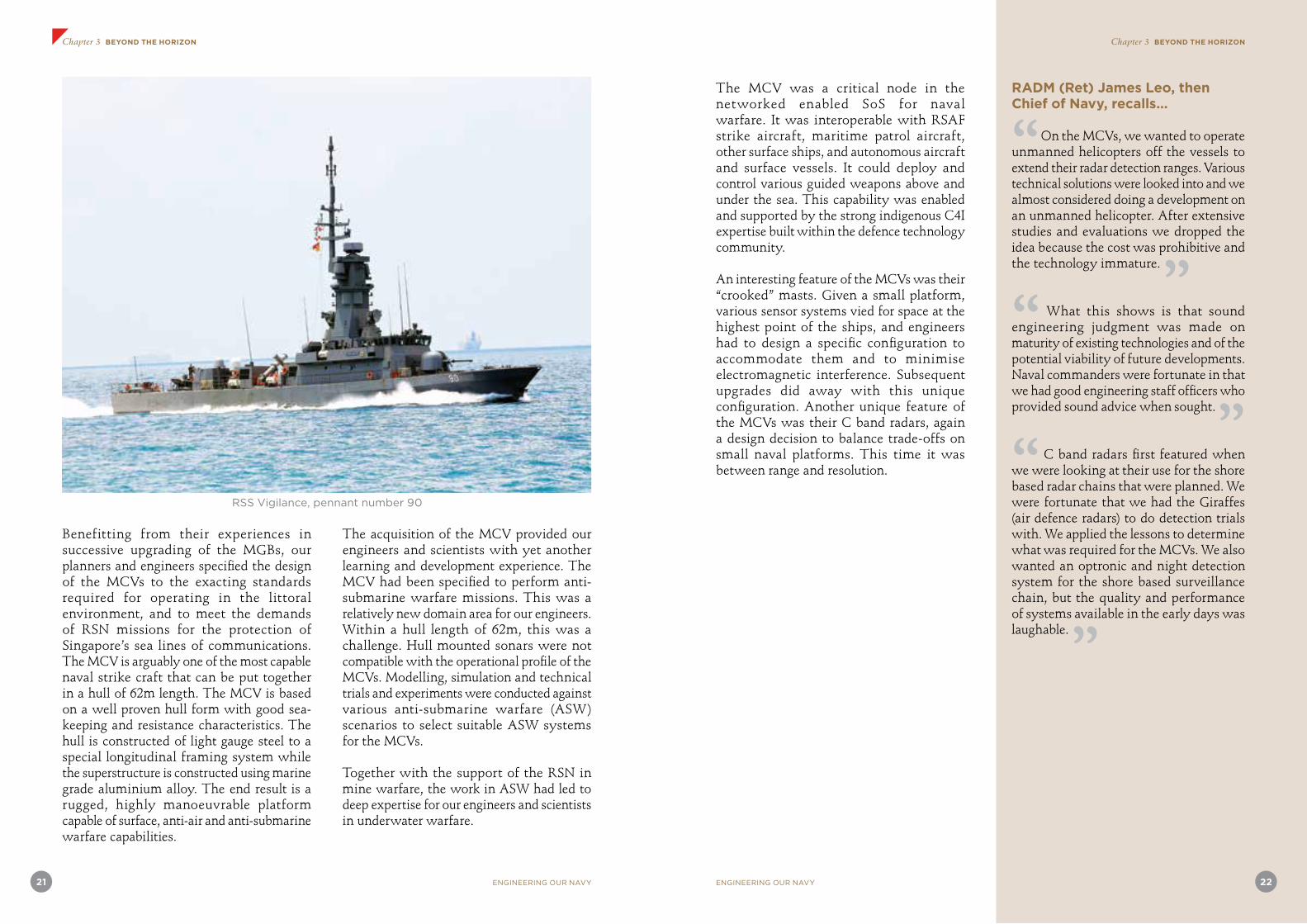
Benefitting from their experiences in successive upgrading of the MGBs, our planners and engineers specified the design of the MCVs to the exacting standards required for operating in the littoral environment, and to meet the demands of RSN missions for the protection of Singapore’s sea lines of communications. The MCV is arguably one of the most capable naval strike craft that can be put together in a hull of 62m length. The MCV is based on a well proven hull form with good sea-keeping and resistance characteristics. The hull is constructed of light gauge steel to a special longitudinal framing system while the superstructure is constructed using marine grade aluminium alloy. The end result is a rugged, highly manoeuvrable platform capable of surface, anti-air and anti-submarine warfare capabilities.
The acquisition of the MCV provided our engineers and scientists with yet another learning and development experience. The MCV had been specified to perform anti-submarine warfare missions. This was a relatively new domain area for our engineers. Within a hull length of 62m, this was a challenge. Hull mounted sonars were not compatible with the operational profile of the MCVs. Modelling, simulation and technical trials and experiments were conducted against various anti-submarine warfare (ASW) scenarios to select suitable ASW systems for the MCVs.
Together with the support of the RSN in mine warfare, the work in ASW had led to deep expertise for our engineers and scientists in underwater warfare.
The MCV was a critical node in the networked enabled SoS for naval warfare. It was interoperable with RSAF strike aircraft, maritime patrol aircraft, other surface ships, and autonomous aircraft and surface vessels. It could deploy and control various guided weapons above and under the sea. This capability was enabled and supported by the strong indigenous C4I expertise built within the defence technology community.
An interesting feature of the MCVs was their “crooked” masts. Given a small platform, various sensor systems vied for space at the highest point of the ships, and engineers had to design a specific configuration to accommodate them and to minimise electromagnetic interference. Subsequent upgrades did away with this unique configuration. Another unique feature of the MCVs was their C band radars, again a design decision to balance trade-offs on small naval platforms. This time it was between range and resolution.
RADM (Ret) James Leo, then Chief of Navy, recalls…
“ On the MCVs, we wanted to operate unmanned helicopters off the vessels to extend their radar detection ranges. Various technical solutions were looked into and we almost considered doing a development on an unmanned helicopter. After extensive studies and evaluations we dropped the idea because the cost was prohibitive and the technology immature. ”“ What this shows is that sound engineering judgment was made on maturity of existing technologies and of the potential viability of future developments. Naval commanders were fortunate in that we had good engineering staff officers who provided sound advice when sought. ”“ C band radars first featured when we were looking at their use for the shore based radar chains that were planned. We were fortunate that we had the Giraffes (air defence radars) to do detection trials with. We applied the lessons to determine what was required for the MCVs. We also wanted an optronic and night detection system for the shore based surveillance chain, but the quality and performance of systems available in the early days was laughable. ”
RSS Vigilance, pennant number 90

23 ENGINEERING OUR NAVY ENGINEERING OUR NAVY 24
Chapter 3 BEYOND THE HORIZON Chapter 3 BEYOND THE HORIZON
Development of the 62m Victory- class MCV (1984 to 1992) By Mr Quek Pin Hou
From MGB to MCV
The completion of the MGBs in 1975 marked a very significant milestone for the RSN. It scored a first in Southeast Asia for a small nation’s little navy to have successfully integrated a sophisticated fire control radar to a battle proven anti-ship missile, and successfully fired the missiles in actual sea trials. The RSN had acquired the technological expertise and had trained combat officers and technical personnel to operate and maintain the sophisticated and operationally effective missile armed boats.
The fact that the Royal Thai Navy (RTN) would, in 1975, procure three MGBs of similar specifications and design from Singapore Shipbuilding and Engineering (SSE) with the blessing of the RSN, was a further endorsement of its standing in the eyes of another regional navy.
However, towards the end of the 1970s, another regional navy acquired a longer range active homing missile with advanced fire control radar. It was increasingly felt that the shorter range Gabriel missile, limited to radar horizon range, was a significant operational disadvantage.
In 1979, a study was made to build three larger 57m missile armed craft to be equipped with longer range active homing missiles. Another proposal was to upgrade the existing MGB by removing two to three of the Gabriel missiles to be replaced with longer range active homing missiles. However, a decision was not made until early 1983 to upgrade the MGB, and later in December 1983 to build six larger 62m MCVs.
The lapse of time from 1977 when the RTN MGBs were completed to December 1983
when the decision was made to build the MCVs meant that many of the engineers and technical officers had left the organisation or changed assignments. Other senior technologists who remained were also by then heavily committed to other project assignments.
Two key officers, however, still remained: myself, the project director of MGB project after Mr Cheong Quee Wah, and Mr Ho Jin Yong, a key systems engineer in the MGB project who later became the Officer Commanding of the Missile Maintenance Facility. A third officer, Mr Alan Bragassam who was experienced in the ship platform systems, was recalled from the private sector. RADM (Ret) Larry Loon from Naval Plans Department served as the operations manager and leader in operational support planning.
Operational Requirements and System Configuration Study for the MCV
In early 1984, the RSN engaged a consultant to help review the operational requirements and study the system configuration to best meet the RSN’s needs. This better ensured a comprehensive operational requirement definition, and various system configuration options were examined before defining the preferred system configuration with sufficient growth potential.
The operational requirement review established the capabilities and possible solutions for the following requirements:
• Radar air and surface surveillance • Ship-to-ship missile • Anti-air defence • Anti-missile defence • Sub-surface surveillance and anti-
submarine • Electronic warfare and electronic support
measures (ESM) • Tactical communications intelligence
(TACOMINT)
• Surface and anti-air gunnery • Internal and external communications • Ship systems performance
These specific operational requirements then served as guiding documents for the respective system teams in the joint project team from the then Defence Materials Organisation (DMO), DSO and the RSN, to draw up systems specifications and potential solution options which would form the tender specifications for a later phase of acquisition procurement.
With the experience from the MGB programme, guidance was given to the respective project teams to draw up the system configuration design in mid 1985.
Experience from the MGB Programme
The choice of the MCV main strike weapon system, namely the ship-to-ship missile, was largely influenced by the experience of the MGB programme. Apart from the fact that missile range advantage over the competitor is paramount, the other important point was to avoid complicated and problematic radar/missile radiofrequency (RF) control interface and manual optical control interface. The radar/missile control interface would require complex hardware and software design, extensive factory level testing and calibration, and even more elaborate harbour and sea environment testing and calibration. In the MGB experience, these took extensive efforts at the factory level, and many months of extensive testing and calibration efforts by highly trained technical personnel. The optical control interface likewise involved complicated hardware and software design and testing. It further required extensive operator training using shipboard simulators.
The choice of using only active homing ship- to-ship missile for the MCV programme avoided the most problematic technical uncertainty in the real-time RF control
interface. The overall scale and complexity of the MCV systems integration and requirements for ICIT – though much larger than the MGB programme due to the sheer number of different weapon systems – were more manageable, less uncertain and laborious. This was thanks to the absence of major RF control calibration and testing.
Another real-life experience centred on the test-firing of missiles which also had its origin in the MGB programme. With the best of effort and intention in live-firing test, there was always the concern of missile malfunction in-flight, and the attendant contractual responsibility of the missile supplier. A rather interesting story on the Harpoon missile system procurement for the MCV (also the upgrading of the MGBs) is thus worthy of mention here.
The Harpoon is a US missile system which was subject to US Foreign Military Sales (FMS) control. For the MCV and MGB upgrading programmes, the US Government (USG) had decided that the Harpoon missile rounds (the flying ammunition round) would only be supplied under the FMS regulations, which meant the missiles would be delivered via the US Military supply channel according to FMS terms and conditions. Basically, that meant the missiles would be fired ‘at our own risk’, with no recourse for any malfunction from the FMS. How then could we solve the great uncertainty for the Harpoon missile, should it malfunction or miss the target during firing tests?
The Harpoon shipboard system and the missile rounds were both supplied by the US manufacturer McDonnell Douglas. The USG’s decision only concerned the missile rounds and not the Harpoon shipboard equipment. US FMS did not deal with this, and it had to be bought separately under commercial terms. USG might have thought that by controlling the missile supply, they actually could

25 ENGINEERING OUR NAVY ENGINEERING OUR NAVY 26
Chapter 3 BEYOND THE HORIZON Chapter 3 BEYOND THE HORIZON
control the entire deal and the entire Harpoon system supply.
This was where we had a breakthrough. We told McDonnell Douglas in a preliminary discussion that even though the missile rounds were supplied by USG, USG only acted as an intermediary. We would be calling tenders to procure the shipboard systems, and we would need to evaluate the entire system performance cost effectiveness together with the missile rounds supplied through the FMS channel. During the pre-tender discussion with McDonnell Douglas, we raised the issue of performance guarantee for the missile rounds in firing tests. After a few rounds of discussion, we managed to convince McDonnell Douglas to consider the supply of shipboard systems and the missile rounds as a total aggregate business, only that they were sold through different channels. If we did not find the overall system performance-wise cost-effective, McDonnell Douglas risked losing the shipboard deal in our procurement tender evaluation, and with it the entire system supply. They would thus risk losing the missile supply business through the FMS as well, and that would be the real centre of gravity of the whole deal.
We also convinced McDonnell Douglas that while they were unable to deviate from US FMS conditions which stated they could not provide missile round warranty (i.e. they could not provide terms more favourable to foreign buyers than USG), nothing would stop them from providing us a contractual performance bond predicated on the good performance of the missile in firing tests. Should the missile malfunction, we would obtain financial compensation via the performance bond. We argued that as a business proposition, McDonnell Douglas would be selling a very sizeable number of rounds at great revenue, and ‘insuring’ the risk of one round out of a great many ought to be commercially viable.
McDonnell Douglas finally bought our argument and agreed to provide us a contractual bank guarantee to cover one firing round for each class of ship – the MCV and the upgraded MGB. In the unlikely event of a repeat missile malfunction, the contract also defined the terms and processes for detailed technical and instrumentation analysis, subject to mutual discussion and negotiation, to find suitable resolutions.
With the above missile firing performance test uncertainty largely resolved, McDonnell Douglas participated in the shipboard system supply tender, and was the eventual winner for both the MCV and upgraded MGB ship-to-ship missile system supplies.
SSE as Prime Contractor
The initial thinking on the project management was for DMO to manage the project directly, who would then hire a systems integrator to carry out the detailed task of systems integration. The systems integration task mainly concerned the inter-weapon systems interface specification and installation control. Initially, the systems integrator was to report directly to the DMO project team.
As this was a large-scale state-of-the-art naval project, MINDEF top management had also intended to use the project as a platform not only to build up the capability of SSE just as a shipbuilder, but also as a warship prime contractor with the ability to design and build future integrated ship and weapons systems as a total package. SSE would also engage Singapore Electronics Engineering Ltd (SEEL, now ST Electronics) to work closely with the systems integrator and DMO technical teams on weapons systems matters. This would have the potential to elevate SSE and SEEL working together to that of a full-fledged warship builder.
This significant change in approach happened
just before the award of the platform contract and all the weapons systems and systems integration contract. This change would require SSE to take over the hiring of the systems integrator under its contract, and SSE would then be contractually directly responsible to DMO for the delivery of the entire MCV system.
While all the players in the overall project had essentially remained the same, this particular change in system delivery did significantly change the contractual role of SSE as the prime contractor. SSE would have contractual responsibility, albeit on paper, to ensure integrated system performance beyond that of a ship platform supplier.
The complexity of the large number of system interfaces, coupled with the new inject of SSE as the prime contractor, led to added complexity for the MCV project. The prime contractor, being a MINDEF controlled company, would finally report back to MINDEF management just like the DMO project team. There were thus unavoidable tensions and conflicts between the DMO project management team and the prime contractor where the responsibilities overlapped or where boundary lines were not entirely clear. This presented significant additional challenges for the DMO project team in the overall MCV project management.
Mast Configuration Design Optimisation
The MCV mast consisted of two parts – the main mast which was part of the main ship structure, and the auxiliary mast which would carry additional antennas and equipment above the main mast.
The heavy items were the rotating air/surface search radar, and the front and back air/surface tracking radar. The air/surface search radar was placed on the main mast top platform. The front and back tracking radar could be
easily placed on lower pedestals in front and behind the main mast.
The highest points were normally reserved for the ESM and TACOMINT antennas. This would require an auxiliary mast to be erected on the main mast, normally standing behind the search radar.
There were additional requirements arising from the antenna pattern and EMI consideration of the ESM and TACOMINT antennas that they should be placed concentric with the search radar centre of rotation. The state-of-the-art in the mid 1980s’ ESM and TACOMINT system that we had selected did not have enough computing power to compensate for two issues:
• The antenna bearing pattern and side-lobe asymmetry when their antennas were not concentric with the search radar and other reflective structures below them
• The coordinate and bearing parallax effects between the ESM, TACOMINT bearing measurements and the search radar coordinate and bearing measurements, with non-concentric origins
It was therefore necessary to bring the centres of ESM and TACOMINT back to the centre line, concentric with the search radar centre of rotation. This could actually be achieved by slanting the auxiliary mast forward after it rose above the search radar. The slant angle and slant length were then determined to locate the TACOMINT and ESM antennas directly above the search radar centre line. The connecting cables for the TACOMINT and ESM were run on the interior of the auxiliary mast and ESM cables were run through the interior of the TACOMINT centre pole. The navigation radar and communications antennas were further located along the slant mast with suitable mounting fixture designs.

27 ENGINEERING OUR NAVY ENGINEERING OUR NAVY 28
Chapter 3 BEYOND THE HORIZON Chapter 3 BEYOND THE HORIZON
The shipbuilder went through detailed mechanical design and choice of material for the slant mast design to attain the required mechanical strength, rigidity and fatigue life span.
Thorough study by both the mechanical and electrical/electronic experts finally confirmed the feasibility of the design solution. The solution thus achieved optimal electronic performance, avoiding complex equipment modifications and contractual disputes.
Given the state-of-the-art system available then in the mid to late 1980s, the mast design solution was necessary to meet the system interface requirements. It also reflected the DMO project team’s willingness to try out new ways to stretch the envelope, undeterred by conventional norms that the auxiliary mast must normally be straight and upright!
MCV ICIT Programme
The MCV ICIT programme began in early 1990. With the experience gained from the MGB programme both in the MGB ICIT and subsequent operational trials, programme management and scheduling of the MCV ICIT benefitted greatly. The ICIT and trial schedule for various weapons systems combination was planned to be completed in nine months, with a three-month contingency period for unforeseen technical, operational or weather related provisions.
During the sea testing phase for the search radar, one serious incident happened when the search radar from Ericsson, Sweden was damaged due to interference with the ship structure. This resulted in substantial mechanical damage to the front feed horn of the radar. Urgent discussion and design modification work were carried out in the UK. The second set of search radar was modified and substituted for the first ship, while the first set was repaired to be installed on the second ship. Through this urgent swap action,
the first ship's ICIT was able to recover much of the time lost due to the incident.
The first MCV successfully completed the torpedo firing, surface gun firing, and Harpoon missile firing by the fourth quarter of 1990, thanks to generally favourable weather and minimal technical glitches. Since the anti-air firing phase and anti-air, anti-missile missile firing were still under a separate joint development programme with IAI and Rafael, a decision was made to reschedule these activities to a later phase. The essential part of the first MCV, RSS Victory ICIT was considered completed by the end of 1990.
The upgraded version of the
Victory-class MCV
DSTA delivered RSS Valour, the final upgraded MCV to the RSN in September 2013. The upgraded MCVs are now equipped with enhanced and persistent surveillance capabilities to ‘see further’. They are fitted with a modern and customised Combat Management System (CMS) to help the Combat Information Centre (CIC) team make faster and more effective decisions.
In delivering this upgrade, the DSTA team worked within the constraints of the existing platform and overcame challenges of limited ship capacities such as the lack of space on board. An example is the integration of the UAV launcher at the aft deck. As the launching clearance for the UAV overlaps with the safety clearance area of the nearby missile launchers, the team conceptualised and delivered an innovative turntable to mount the UAV launcher. When rotated, the UAV launching clearance is achieved, and when kept, the missile clearances are maintained.
Paying close attention to detail, the team continuously sought process efficiency and improved task productivity to enable a high trial success rate. The team thus completed the upgrade programme ahead of schedule, enabling the squadron of upgraded MCVs
to be operationalised much earlier than planned.
Commissioned in the 1990s, the MCVs have served as the principal strike craft of the RSN. To support the SAF’s transformation, DSTA undertook the task of upgrading the MCV with a new suite of combat capabilities.
One of the key features of this upgrade is the unprecedented integration of the ScanEagle UAV system onto the MCV. The UAV was initially designed to be used on land. In its original form, the UAV is too large for the MCV. DSTA thus came up with the innovative idea of fitting the UAV launcher on a turn-table, allowing the UAV to be launched at optimal angle while maintaining sufficient clearance from nearby weapons when it is not in use.
The team also customized a CMS for the MCV, enhancing the CIC workflow as a result. To improve operational efficiency, DSTA mounted the CMS onto the Commanding Officer’s chair, enabling him to access key information at a touch.
The upgraded MCVs have since demonstrated their operational capabilities in numerous exercises, such as the joint live-firing exercise with the United States Navy in July 2012.
Article credit: DSTA
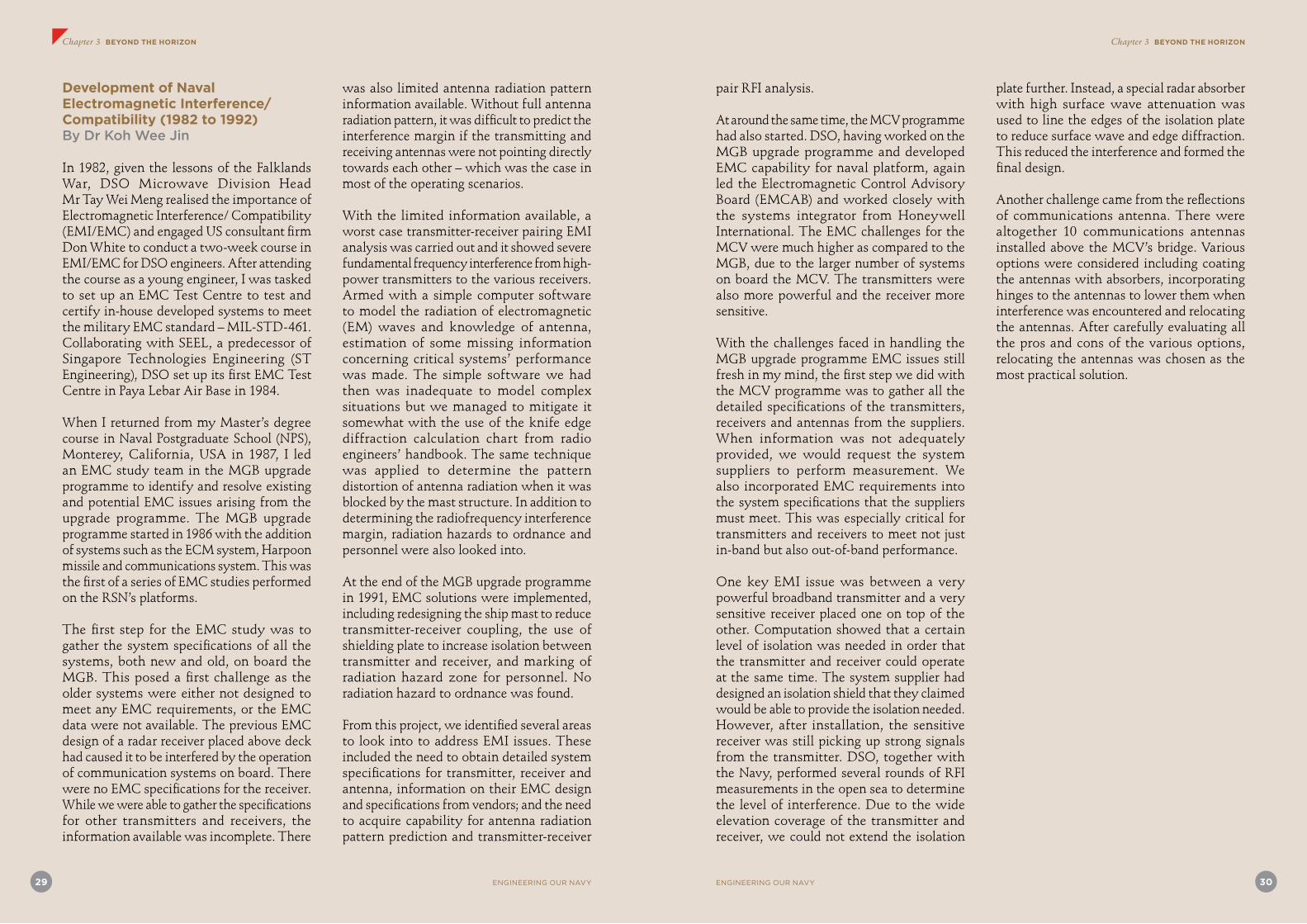
ENGINEERING OUR NAVY 30
Chapter 3 BEYOND THE HORIZON
29 ENGINEERING OUR NAVY
Chapter 3 BEYOND THE HORIZON
Development of Naval Electromagnetic Interference/Compatibility (1982 to 1992) By Dr Koh Wee Jin
In 1982, given the lessons of the Falklands War, DSO Microwave Division Head Mr Tay Wei Meng realised the importance of Electromagnetic Interference/ Compatibility (EMI/EMC) and engaged US consultant firm Don White to conduct a two-week course in EMI/EMC for DSO engineers. After attending the course as a young engineer, I was tasked to set up an EMC Test Centre to test and certify in-house developed systems to meet the military EMC standard – MIL-STD-461. Collaborating with SEEL, a predecessor of Singapore Technologies Engineering (ST Engineering), DSO set up its first EMC Test Centre in Paya Lebar Air Base in 1984.
When I returned from my Master’s degree course in Naval Postgraduate School (NPS), Monterey, California, USA in 1987, I led an EMC study team in the MGB upgrade programme to identify and resolve existing and potential EMC issues arising from the upgrade programme. The MGB upgrade programme started in 1986 with the addition of systems such as the ECM system, Harpoon missile and communications system. This was the first of a series of EMC studies performed on the RSN’s platforms.
The first step for the EMC study was to gather the system specifications of all the systems, both new and old, on board the MGB. This posed a first challenge as the older systems were either not designed to meet any EMC requirements, or the EMC data were not available. The previous EMC design of a radar receiver placed above deck had caused it to be interfered by the operation of communication systems on board. There were no EMC specifications for the receiver. While we were able to gather the specifications for other transmitters and receivers, the information available was incomplete. There
was also limited antenna radiation pattern information available. Without full antenna radiation pattern, it was difficult to predict the interference margin if the transmitting and receiving antennas were not pointing directly towards each other – which was the case in most of the operating scenarios.
With the limited information available, a worst case transmitter-receiver pairing EMI analysis was carried out and it showed severe fundamental frequency interference from high-power transmitters to the various receivers. Armed with a simple computer software to model the radiation of electromagnetic (EM) waves and knowledge of antenna, estimation of some missing information concerning critical systems’ performance was made. The simple software we had then was inadequate to model complex situations but we managed to mitigate it somewhat with the use of the knife edge diffraction calculation chart from radio engineers’ handbook. The same technique was applied to determine the pattern distortion of antenna radiation when it was blocked by the mast structure. In addition to determining the radiofrequency interference margin, radiation hazards to ordnance and personnel were also looked into.
At the end of the MGB upgrade programme in 1991, EMC solutions were implemented, including redesigning the ship mast to reduce transmitter-receiver coupling, the use of shielding plate to increase isolation between transmitter and receiver, and marking of radiation hazard zone for personnel. No radiation hazard to ordnance was found.
From this project, we identified several areas to look into to address EMI issues. These included the need to obtain detailed system specifications for transmitter, receiver and antenna, information on their EMC design and specifications from vendors; and the need to acquire capability for antenna radiation pattern prediction and transmitter-receiver
pair RFI analysis.
At around the same time, the MCV programme had also started. DSO, having worked on the MGB upgrade programme and developed EMC capability for naval platform, again led the Electromagnetic Control Advisory Board (EMCAB) and worked closely with the systems integrator from Honeywell International. The EMC challenges for the MCV were much higher as compared to the MGB, due to the larger number of systems on board the MCV. The transmitters were also more powerful and the receiver more sensitive.
With the challenges faced in handling the MGB upgrade programme EMC issues still fresh in my mind, the first step we did with the MCV programme was to gather all the detailed specifications of the transmitters, receivers and antennas from the suppliers. When information was not adequately provided, we would request the system suppliers to perform measurement. We also incorporated EMC requirements into the system specifications that the suppliers must meet. This was especially critical for transmitters and receivers to meet not just in-band but also out-of-band performance.
One key EMI issue was between a very powerful broadband transmitter and a very sensitive receiver placed one on top of the other. Computation showed that a certain level of isolation was needed in order that the transmitter and receiver could operate at the same time. The system supplier had designed an isolation shield that they claimed would be able to provide the isolation needed. However, after installation, the sensitive receiver was still picking up strong signals from the transmitter. DSO, together with the Navy, performed several rounds of RFI measurements in the open sea to determine the level of interference. Due to the wide elevation coverage of the transmitter and receiver, we could not extend the isolation
plate further. Instead, a special radar absorber with high surface wave attenuation was used to line the edges of the isolation plate to reduce surface wave and edge diffraction. This reduced the interference and formed the final design.
Another challenge came from the reflections of communications antenna. There were altogether 10 communications antennas installed above the MCV’s bridge. Various options were considered including coating the antennas with absorbers, incorporating hinges to the antennas to lower them when interference was encountered and relocating the antennas. After carefully evaluating all the pros and cons of the various options, relocating the antennas was chosen as the most practical solution.

31 ENGINEERING OUR NAVY ENGINEERING OUR NAVY 32
Chapter 3 BEYOND THE HORIZON Chapter 3 BEYOND THE HORIZON
Upgrading the MCVs
The RSN’s MCVs were successfully upgraded from 2009 to 2013. The performance of the upgraded MCVs has since been validated, with the vessels having been deployed extensively in operational and search and rescue taskings, as well as in live-firing and exercises with foreign navies. Notably, the upgrade went beyond extending the operational lifespan of the MCVs and has included an expansion of their capabilities through the application of innovative solutions.
The MCV upgrade programme preserves the MCVs’ still operationally capable hull built in the 1990s, while undertaking the deliberate and thorough enhancement of their onboard combat systems to equip them with state-of-the-art capabilities. The introduction of advanced surveillance, communications, as well as a modern and customised CMS, has enabled the MCVs to be incorporated into the SAF-wide integrated knowledge-based command and control capabilities.
The post-upgrade MCV, with the straight
mast configuration.
Smart Platform Integration
Space was a major issue, with the limited deck space of the 62m MCV. Through smart platform integration, our engineers were able to optimise the use of the vessel’s existing
hull and equip it with a UAV. The ScanEagle UAV system was a land-based commercial off-the-shelf system. It was typically deployed on the wide flight deck of large ships such as frigates. In its standard configuration, there was insufficient space to launch and recover the ScanEagle UAV on smaller ships such as the MCV.
Enabling Efficient UAV Launch Operations
Our engineers had to explore innovative means to install the launch and recovery systems of the ScanEagle UAV. The MCV’s aft deck area supports a wide range of operations that includes missile firing as well as the launch and recovery of sea boat and mooring operations. Installing the UAV launcher in its standard configuration at the aft deck would use up all the available deck space and prevent the undertaking of other deck operations. As such, our engineers conceptualised a modified ScanEagle UAV launcher mounted on a customised turntable. The turntable can be stowed to allow existing deck operations to continue unimpeded. It also enables optimal UAV launch envelop to be achieved through the controlled rotation of the launcher. The turntable performs its rotation while remaining secured on the ship deck, thereby ensuring that UAV operations can be conducted on board the MCV safely under high sea state conditions. The customised UAV launch system has reduced the overall launch preparation time by 90%. In addition, it can be operated by a single crew member, thus reducing manpower requirement by 66%.
The design of the modified UAV launcher
installed aboard the corvettes after
the upgrade added additional functionality
through a turntable.
Enabling Safe UAV Recovery Operations
The ScanEagle UAV is recovered in-flight using a skyhook arrestor. The skyhook system – which in its original design requires an area of 25m2 – was re-engineered such that it can be extended to recover the UAV and retracted for stowage within a reduced space of 10m2. This reduces the amount of space required by the UAV recovery system by more than 50%. However, the lack of open spaces on deck poses a potential safety risk during the recovery of the UAV. To overcome this and enhance the safety of recovery operation on board the MCV, the UAV was programmed to maintain an angle away from the ship as it flies towards the recovery system.
Innovative Systems Integration
As the SAF transforms into a Third Generation networked fighting force, enabling interconnectivity among its various assets is essential. Therefore, a key element of the MCV upgrade programme was to ensure that the MCVs would be able to interoperate with other assets to achieve higher operational synergy.
The recovery system when fully deployed
(top), and when collapsed (bottom).
Re-conceptualising Mast Layout: Optimised Sensor Suite to See Further
In the pre-upgrade MCV, the arrangement of the sensors on its mast was optimised to reduce the impact of electromagnetic interference. In the upgraded MCV, modern electromagnetic interference management techniques were applied to further mediate the MCV’s electromagnetic environment and facilitate the incorporation of advanced

33 ENGINEERING OUR NAVY ENGINEERING OUR NAVY 34
Chapter 3 BEYOND THE HORIZON Chapter 3 BEYOND THE HORIZON
sensors into a straight and taller mast. The new sensor suite allows the upgraded MCV to sense targets at further distances.
The pre-upgrade MCV with its slanted mast
(left) compared to the upgraded MCV with
its straight mast (right).
The MCV upgrade programme provided a unique opportunity for our engineers to innovate and deliver a wider range of capabilities that have enhanced the operational effectiveness of the MCVs. Since 2013, the upgraded MCVs have contributed to national and international security through operational and search and rescue taskings, as well as its active participation in live-firing and exercises with foreign navies. In 2014, the MCV upgrade programme was awarded the Defence Technology Prize Team (Engineering) Award.
Enabling Platforms to Operate as an SoS
Influencing the battlespace beyond the horizon is not about having bigger or more sophisticated platforms, but the ability to enable individual platforms to work together as an SoS.
Today, with widespread access to the internet and with the pervasiveness of modern
broadband mobile communications and networking technologies, we are used to working in a collaborative environment that has no geographic limits. This was not the case before the current millennium.
The RSN was a first mover in using many of these collaborative technologies, well before they became household words. For example, the RSN was using cellular mobile telephones for communication well before these were available for widespread civilian use. The RSN also used short messaging technologies (SMS) well before SMS was available as a feature in our mobile phones.
Automated Action Information Systems and Digital Communications
The Action Information System (AIS) on board the MGB, upgraded in the late 1980s, was the RSN’s first generation of AIS which was a computerised system to do situation picture compilation. Prior to AIS, naval combat crew were using clear perspex (acrylic glass) writing boards and “china graph” to plot the situation picture. They literally had to write mirrored images/characters (i.e. writing laterally inverted) for the officer-on-watch looking from the other side of the perspex board. AIS replaced all these manual intensive plotting of situation picture with a colour graphic display with map overlays and graphic drawing tools. With the sensor data inputs to AIS, a digital radar video picture was overlaid on top of the AIS map graphical display for tactical situation appreciation, target acquisition, tracking and designation to the weapon systems. It changed the entire operations in the CIC which traditionally used the radar plan position indicator (PPI) monochrome display for target acquisition, tracking and designation to the weapons. The use of colour also opened a new dimension in situational awareness whereby tactical entities displayed on the screen can be easily differentiated
allowing a better appreciation of the situation picture.
The standalone communication unit (SACU) was the first RSN tactical datalink system to integrate with the AIS for the exchange and relay of target information, short text messages and other data. Although the encrypted short text message was limited by the speed and the number of characters, it was quite similar to the mobile SMS we have today on our mobile phones. The message could also be relayed to another wireless network via SACU. The additional integration of Differential Global Positioning System in the 1990s led to more enhancements to the AIS and SACU with time-sensitive and more accurate position data to improve RSN operations.
Various RSN platforms such as the MCV, coastal patrol craft or patrol vessel, landing ship tank, maritime patrol aircraft and the shore coastal surveillance centre fitted with AIS and SACU would have the capability to exchange target information including short text messages in a secure and wireless network-centric environment.
The deployment of these sophisticated information systems led the RSN to require that weapon electronics officers (WEOs) serve on board its ships starting from the upgraded MGBs. They were initially named electronics technical officers (ETOs) before this was changed to WEO.

ENGINEERING OUR NAVY 3635 ENGINEERING OUR NAVY
Chapter 3 BEYOND THE HORIZON
COLLABORATIVE SYSTEMS – FORCE MULTIPLICATION
An SoS is defined as a set or arrangement of systems that results when independent and useful systems are integrated into a larger system that delivers unique capabilities. In a collaborative SoS, the component systems interact more or less voluntarily to fulfil agreed upon central purposes.
Three examples of collaborative systems are described in this chapter showing different aspects of emergent capabilities that can result from such collaboration. The first is the collaborative system (of systems) resulting from connecting various platform systems (ships and aircraft) together. Here the result is a significant increase in combat power. The second is the integration of two information systems – a real time coastal surveillance system and a sense-making system. Here the pay-off is a significant capability leap in the information domain, providing enhanced capabilities in early warning and actionable insights for strategic decision making. The third example is the collaboration across organisations and national boundaries enabling organisations and nations to work together to achieve shared outcomes beyond the means of a single entity.
The Surface Task Group and the Maritime Air Task Force
Collaborative systems (of independent systems each designed for a particular purpose) enable operational effects to be enhanced in both scale and scope. In the case of a naval surface task group for example, independent naval platforms can collaborate to provide wide-area surveillance coverage or through cooperative engagement to saturate an enemy’s defences. The further integration of an airborne
surveillance platform will provide significantly improved over-the-horizon capabilities. Adding strike aircraft to this collaborative system for example will additionally confer a small surface force the capability to take on a much larger enemy force by concentrating combat power rapidly to achieve local superiority where it counts.
Maritime Air Strike Force
Surface Task Group
A maritime task force’s
capabilities are multiplied manifold with
the inclusion of aircraft.
A Collaborative Surveillance and Sense-Making System
When our naval planners and engineers were putting in place a coastal surveillance and command and control (C2) capability for the Singapore Straits and its approaches, they faced significant challenges. Maritime traffic of all sorts and sizes operated in the Straits and numbered several hundred at any one time. Just putting in place a chain of surveillance radars did not quite provide an adequate capability to meet the maritime security needs. A radar system could detect various targets but could not provide a fully recognised sea situation picture. Vessels closely
Chapter FourThe AIS also had a state-of-the-art (at that time) digital scan converter which converted the traditional radar PPI picture into a raster-scan picture for the Barco colour-monitor. Another impressive feature of the AIS was its ability to track large numbers of contacts and display their course and speed automatically – this improved the capacity of the combat systems many-fold using inputs from both the MGB navigation radar and fire control radar.
With the SACU datalink, information exchange and sharing between ships was effortless with the AIS. Watch keepers used the AIS system to "chat" between ship teams – before the AIS, such chat was unheard of.
Those were the days... while the MGB squadron office was excited about replacing the manual-type writers with desk-top computers... ship crews on the MGBs were also going through the transformation of their fighting capabilities with the new AIS and a whole host of other upgraded systems on the ship.
COL (Ret) Choo Ah Choon, the first WEO to be appointed to serve on board the upgraded MGB recalls…
The need for having an electronic technical officer on the strike craft was because of the increased sophistication of electronic sensors and weapons that were being introduced during the MGB Upgrade Programme. The AIS and SACU were additions that enhanced the warfighting capabilities of the old MGB to a completely new level.
The vertical plot on the MGB – a labour intensive picture compiler – was made obsolete in the mid 1980’s with the introduction of the new AIS. The most obvious feature of the AIS was the colour Barco display in its main console... at that time it was a very impressive piece of equipment that provided the situation picture in fine details. I remember the naval officers, warrant officers and specialists commenting that they were glad that their manual plotting days were over. Of course, this was in comparison to what the vertical plot could do then. The AIS allowed synthetic contacts, digital chart and even real-time radar picture to be overlaid and presented on the main display – providing a truly complete situation picture to the CIC team.
To me, the true advancement in capabilities was beneath the console and what the new AIS was designed to do. Its abilities to interface with the various sensors and weapons systems was a big leap in capability, as it allowed contact information to be processed for detection, identification and classification. With the AIS, the interface with the ESM system was also enhanced and bearing lines could be sent across automatically or selectively. The system interface also allowed target designation to weapons systems on board for engagement – completing the full detection to engagement cycle for the operators.

37 ENGINEERING OUR NAVY ENGINEERING OUR NAVY 38
Chapter 4 COLLABORATIVE SYSTEMS Chapter 4 COLLABORATIVE SYSTEMS
The concepts that go into creating a reliable collaborative system
An integrated maritime awareness
picture of the type used by the Maritime Security Task Force.
spaced together gave rise to multi-path effects complicating the compilation of a recognised sea situation picture. High relative humidity, regular rain and thunderstorms contributed to the difficulty of detection and identification using radar and electro-optical sensors. C band radars had to be used in conjunction with X band radars to provide for good performance in both range and resolution. Electro-optical sensors using the 8 to 12 micron wavelengths had to be replaced with those using the 3 to 5 micron wavelengths to suit our local operating environment. Harbour craft had to be equipped with transponders to facilitate identification.
Surveillance systems are good to provide actionable real time information such as
directing naval platforms for investigation or for sensor and weapon employment. However, surveillance systems have inherent limitations in that by themselves they lack contextual information and insights and only display the current situation. Integration with a sense-making system confers significant capabilities that each of the individual systems cannot provide. The sense-making systems can provide contextual information, insights and foresight using data analytics from various sources of data.
The diagram below is a conceptual depiction of the integration of a maritime surveillance system with a sense-making system providing both actionable real time information as well as actionable foresight and insight.
Real time tracks
Current Situation
Past, Present, Future
Actionable Foresight, Insight
Context, Trends, Anomalies, Patterns, Early Warning
Active Surveillance Data
Open Source Data
Other Data
Actionable real time InformationData Fusion & Display
Data Analytics
Sense-making System
Real-time Surveillance System Collaboration Across Organisations
and National Boundaries
Engineering collaborative networks can enable multilateral forces to work together for maritime security, humanitarian and peacekeeping or enforcement operations. The development of the Changi C2 Centre is an example.
Changi C2 Centre
The Changi C2 Centre comprises three functional centres, namely, the Singapore Maritime Crisis Centre (SMCC), the Information Fusion Centre (IFC), and the Multinational Operations and Exercises Centre (MOEC).
• SMCC: The RSN’s Maritime Security Task Force headquarters and elements from the Maritime Port Authority of Singapore and the Police Coast Guard make up the SMCC. The SMCC plans its maritime security operations from a common room known as the Inter-Agency Co-ordination
Centre, in the event of maritime incidents or crises.
• IFC: The IFC is a centre where maritime information is collated and shared with like-minded regional and international security partners, to enhance awareness of the maritime security situation, and where necessary, serve to cue or shape maritime security operations.
• MOEC: The MOEC is a centre for the planning and conduct of multinational operations or exercises. For example, the MOEC can be used to host exercises conducted by the Five Power Defence Arrangements and the Western Pacific Naval Symposium. Should the need arise, the MOEC can also be used to facilitate international cooperation in maritime security, humanitarian assistance and disaster relief operations.
International Liaison Officers from France
hard at work during the
2015 Maritime Information Sharing Exercise.
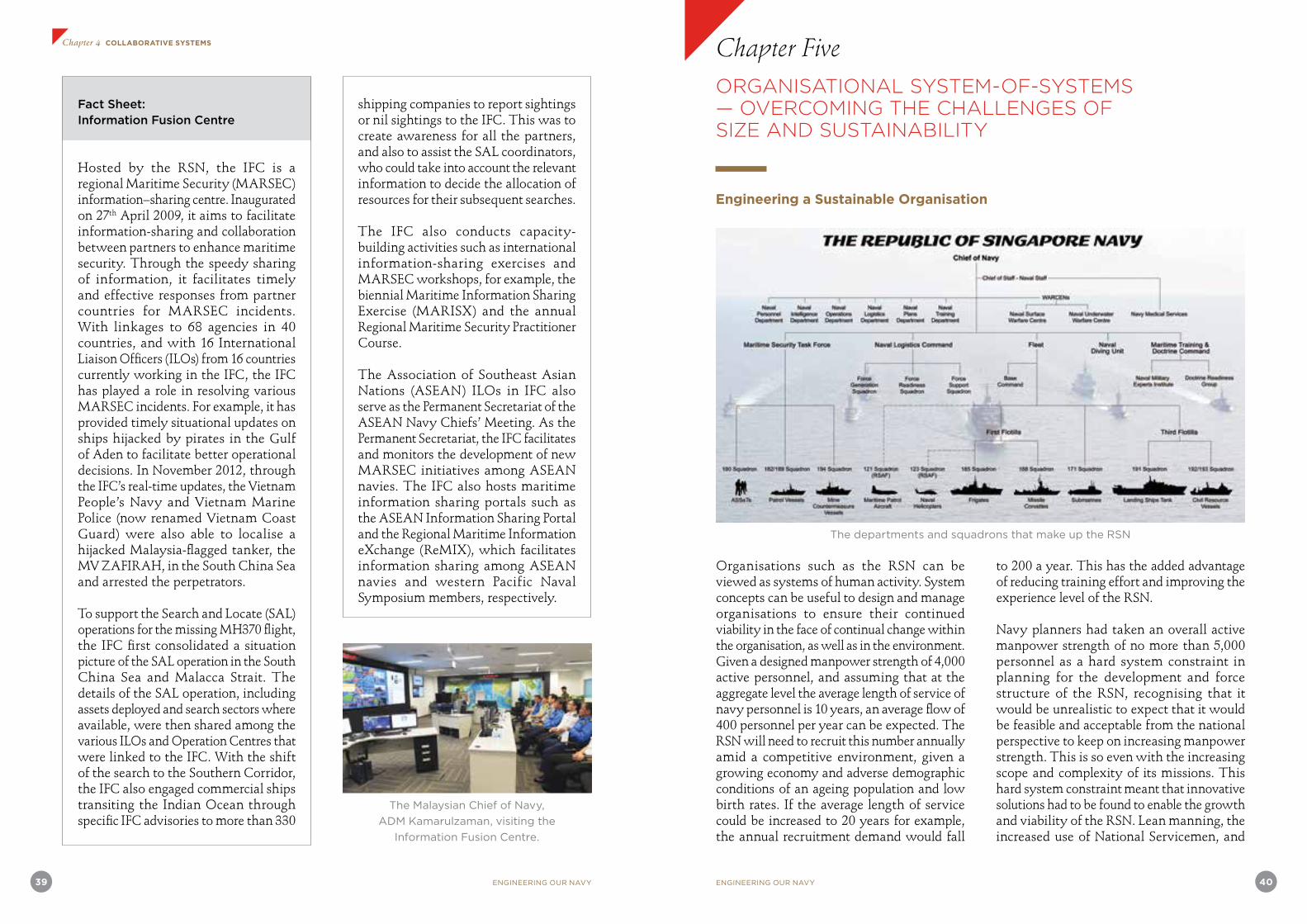
39 ENGINEERING OUR NAVY
Chapter 4 COLLABORATIVE SYSTEMS
ENGINEERING OUR NAVY 40
Fact Sheet: Information Fusion Centre
Hosted by the RSN, the IFC is a regional Maritime Security (MARSEC) information–sharing centre. Inaugurated on 27th April 2009, it aims to facilitate information-sharing and collaboration between partners to enhance maritime security. Through the speedy sharing of information, it facilitates timely and effective responses from partner countries for MARSEC incidents. With linkages to 68 agencies in 40 countries, and with 16 International Liaison Officers (ILOs) from 16 countries currently working in the IFC, the IFC has played a role in resolving various MARSEC incidents. For example, it has provided timely situational updates on ships hijacked by pirates in the Gulf of Aden to facilitate better operational decisions. In November 2012, through the IFC’s real-time updates, the Vietnam People’s Navy and Vietnam Marine Police (now renamed Vietnam Coast Guard) were also able to localise a hijacked Malaysia-flagged tanker, the MV ZAFIRAH, in the South China Sea and arrested the perpetrators.
To support the Search and Locate (SAL) operations for the missing MH370 flight, the IFC first consolidated a situation picture of the SAL operation in the South China Sea and Malacca Strait. The details of the SAL operation, including assets deployed and search sectors where available, were then shared among the various ILOs and Operation Centres that were linked to the IFC. With the shift of the search to the Southern Corridor, the IFC also engaged commercial ships transiting the Indian Ocean through specific IFC advisories to more than 330
shipping companies to report sightings or nil sightings to the IFC. This was to create awareness for all the partners, and also to assist the SAL coordinators, who could take into account the relevant information to decide the allocation of resources for their subsequent searches.
The IFC also conducts capacity-building activities such as international information-sharing exercises and MARSEC workshops, for example, the biennial Maritime Information Sharing Exercise (MARISX) and the annual Regional Maritime Security Practitioner Course.
The Association of Southeast Asian Nations (ASEAN) ILOs in IFC also serve as the Permanent Secretariat of the ASEAN Navy Chiefs’ Meeting. As the Permanent Secretariat, the IFC facilitates and monitors the development of new MARSEC initiatives among ASEAN navies. The IFC also hosts maritime information sharing portals such as the ASEAN Information Sharing Portal and the Regional Maritime Information eXchange (ReMIX), which facilitates information sharing among ASEAN navies and western Pacific Naval Symposium members, respectively.
The Malaysian Chief of Navy,
ADM Kamarulzaman, visiting the
Information Fusion Centre.
to 200 a year. This has the added advantage of reducing training effort and improving the experience level of the RSN.
Navy planners had taken an overall active manpower strength of no more than 5,000 personnel as a hard system constraint in planning for the development and force structure of the RSN, recognising that it would be unrealistic to expect that it would be feasible and acceptable from the national perspective to keep on increasing manpower strength. This is so even with the increasing scope and complexity of its missions. This hard system constraint meant that innovative solutions had to be found to enable the growth and viability of the RSN. Lean manning, the increased use of National Servicemen, and
Organisations such as the RSN can be viewed as systems of human activity. System concepts can be useful to design and manage organisations to ensure their continued viability in the face of continual change within the organisation, as well as in the environment. Given a designed manpower strength of 4,000 active personnel, and assuming that at the aggregate level the average length of service of navy personnel is 10 years, an average flow of 400 personnel per year can be expected. The RSN will need to recruit this number annually amid a competitive environment, given a growing economy and adverse demographic conditions of an ageing population and low birth rates. If the average length of service could be increased to 20 years for example, the annual recruitment demand would fall
Chapter Five
The departments and squadrons that make up the RSN
ORGANISATIONAL SYSTEM-OF-SYSTEMS — OVERCOMING THE CHALLENGES OF SIZE AND SUSTAINABILITY
Engineering a Sustainable Organisation
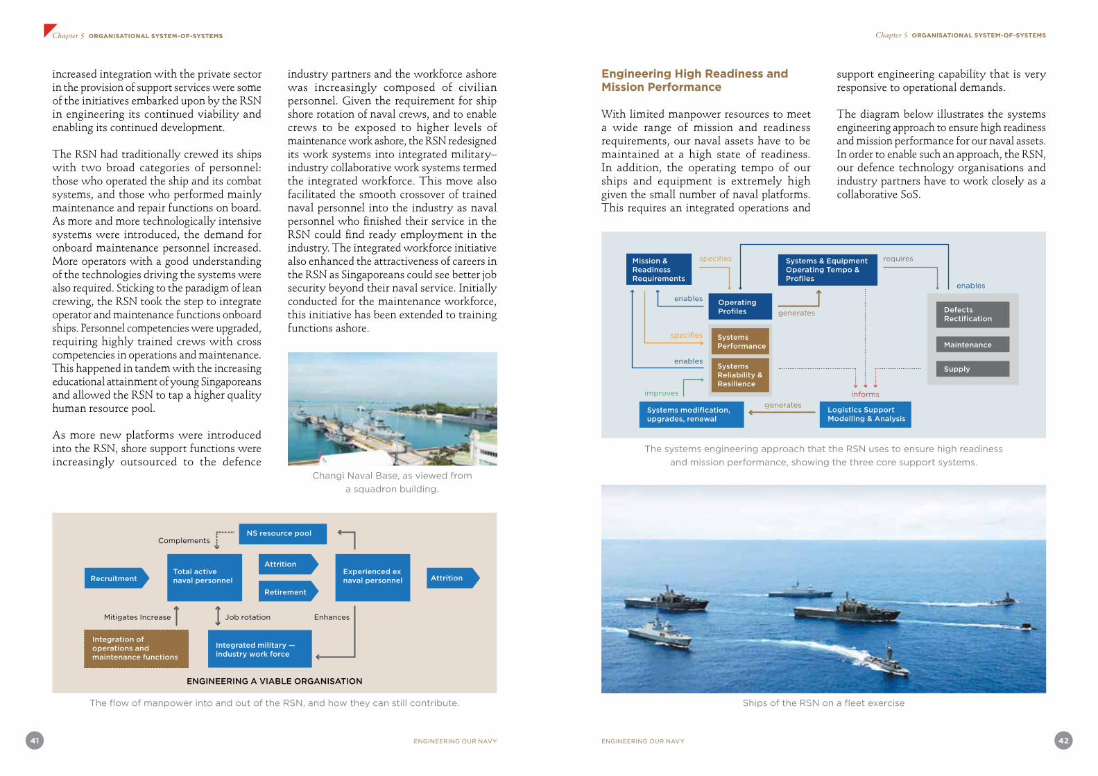
41 ENGINEERING OUR NAVY ENGINEERING OUR NAVY 42
Chapter 5 ORGANISATIONAL SYSTEM-OF-SYSTEMS Chapter 5 ORGANISATIONAL SYSTEM-OF-SYSTEMS
The flow of manpower into and out of the RSN, and how they can still contribute.
increased integration with the private sector in the provision of support services were some of the initiatives embarked upon by the RSN in engineering its continued viability and enabling its continued development.
The RSN had traditionally crewed its ships with two broad categories of personnel: those who operated the ship and its combat systems, and those who performed mainly maintenance and repair functions on board. As more and more technologically intensive systems were introduced, the demand for onboard maintenance personnel increased. More operators with a good understanding of the technologies driving the systems were also required. Sticking to the paradigm of lean crewing, the RSN took the step to integrate operator and maintenance functions onboard ships. Personnel competencies were upgraded, requiring highly trained crews with cross competencies in operations and maintenance. This happened in tandem with the increasing educational attainment of young Singaporeans and allowed the RSN to tap a higher quality human resource pool.
As more new platforms were introduced into the RSN, shore support functions were increasingly outsourced to the defence
industry partners and the workforce ashore was increasingly composed of civilian personnel. Given the requirement for ship shore rotation of naval crews, and to enable crews to be exposed to higher levels of maintenance work ashore, the RSN redesigned its work systems into integrated military–industry collaborative work systems termed the integrated workforce. This move also facilitated the smooth crossover of trained naval personnel into the industry as naval personnel who finished their service in the RSN could find ready employment in the industry. The integrated workforce initiative also enhanced the attractiveness of careers in the RSN as Singaporeans could see better job security beyond their naval service. Initially conducted for the maintenance workforce, this initiative has been extended to training functions ashore.
Changi Naval Base, as viewed from
a squadron building.
Mitigates Increase Job rotation Enhances
Complements
ENGINEERING A VIABLE ORGANISATION
Retirement
Total active naval personnel
Experienced ex naval personnel
Integration of operations and maintenance functions
Integrated military — industry work force
NS resource pool
Recruitment
Attrition
Attrition
Engineering High Readiness and Mission Performance
With limited manpower resources to meet a wide range of mission and readiness requirements, our naval assets have to be maintained at a high state of readiness. In addition, the operating tempo of our ships and equipment is extremely high given the small number of naval platforms. This requires an integrated operations and
support engineering capability that is very responsive to operational demands.
The diagram below illustrates the systems engineering approach to ensure high readiness and mission performance for our naval assets. In order to enable such an approach, the RSN, our defence technology organisations and industry partners have to work closely as a collaborative SoS.
Ships of the RSN on a fleet exercise
The systems engineering approach that the RSN uses to ensure high readiness
and mission performance, showing the three core support systems.
generates
improves
generates
informs
requiresspecifies
specifies
enables
enables
enables
Operating Profiles
Systems Performance
Systems Reliability & Resilience
Defects Rectification
Maintenance
Supply
Systems modification, upgrades, renewal
Logistics Support Modelling & Analysis
Systems & Equipment Operating Tempo & Profiles
Mission & Readiness Requirements

ENGINEERING OUR NAVY 44
Chapter 6 NAVAL PLATFORMS
43 ENGINEERING OUR NAVY
NAVAL PLATFORMS — MULTI-ROLE AND MULTI-DIMENSIONAL
Building a balanced navy with the range of capabilities to meet mission requirements during both peace and war is a major challenge for a navy with a small human resource pool. Given such a constraint, our naval platforms have to adopt lean crewing and play multiple roles.
“The case for larger and more sophisticated ships depends on the role of the Navy in war. With no clear definition of our potential aggressors, their invasion fleets, or their strengths and capabilities, and with no definite knowledge of the conditions and circumstances under which RSN will engage the invading forces in combat, it may be difficult to justify huge expenditures of scarce financial and manpower resources to build a large and powerful navy.”
Excerpt from address by the Minister for Defence, Mr Howe Yoon Chong, at the commissioning ceremony of the coastal patrol craft at Pulau Brani Naval Base on Tuesday, 20th October 1981
Patrol Vessels for Maritime Security Operations
The RSN patrol vessels (PV) had to be designed to provide a cost-effective solution to our maritime security missions. The development of the Fearless-class PVs was the first indigenous naval vessel design and production programme for our engineers. Systems integration of combat systems was also performed indigenously. In addition, the design and development of the C2 system for the PV was also performed by our defence engineers. This programme was a tremendous learning experience and harnessed the capabilities of the entire defence technology community to ensure its success. Its successful completion was a boost in confidence and set the path for subsequent local design and development programmes.
The PVs were designed to replace the coastal patrol craft that were being transferred to the Police Coast Guard (PCG) that the RSN helped to establish. The PCG was initially the Marine Police and performed mainly constabulary missions within the port limits of Singapore. The PCG was established to perform the
Chapter Sixexpanded role of maritime enforcement and security missions extending its area of operations to the entire Singapore Territorial Waters that included the territorial waters around Horsburgh Lighthouse (Pedra Branca).
The PVs were larger than the coastal patrol craft, for better endurance and seakeeping. They formed two squadrons, one of which was designated for shallow water anti-submarine operations and equipped with shipboard sonars and anti-submarine torpedoes.
From lessons learnt in operating in shallow waters, the RSN designed the PVs with waterjet propulsion. These were less susceptible to damage from hitting submerged floating objects such as large logs. These vessels were very manoeuverable and facilitated their ability to perform maritime security patrols as well as warfare missions within the Singapore Strait and its approaches.
The PVs were also equipped with electronic warfare equipment for detection and anti-missile defence. With the advances in electro-optical technology, the PVs were also fitted with electro-optical systems that could control the main 76mm gun of the PV. An unintended effect encountered was that in some specific situations too much smoke from weapon firings affected the ability of these electro-optical systems to maintain their continued tracking of targets and this could pose a safety problem when gun firing was in progress. Our engineers had to make modifications which included adjusting the positioning of the electro-optical sights to resolve the problem.
The success of the PV programme proved the mettle of our naval planners and engineers. The deployment of the PV allowed the MGB and MCV to perform less patrols and to focus on their roles of operations for the seaward defence and security of our sea lines of communications. The PVs also allowed the training of naval officers for junior command
before moving on to command the more sophisticated ships of the RSN. Besides their employment for maritime patrols and security operations the PV also participated with the MGBs and MCVs in naval task group operations and in anti-submarine exercises with international navies.
RSS Daring, pennant number 98
Equipping the PVs
ST Marine, part of ST Engineering, built 12 Fearless-class PVs for the RSN. The RSN awarded the contract to ST Marine in February 1993 and the first of the Fearless-class PV was commissioned in October 1996. The final vessel of the class was commissioned in August 1998.
The first six vessels of the class are armed for anti-submarine warfare missions. The remaining six vessels are for patrols. The 55m PV has a steel monohull with a round bilge semi-displacement hull, incorporating very fine V-shaped frames in the forward sections. The superstructure is constructed in marine grade light alloy. The design of the vessel allows the layout to be reconfigured to accept a range of sensors and weapons systems to meet evolving operational requirements.
The first six vessels are armed with triple tube Whitehead A244S torpedo launchers supplied by Whitehead Alenia. The air defence system is the Simbad twin launcher for the Mistral surface-to-air missile, supplied by MBDA. The Simbad launcher is installed on the RSS Independence Fearless-class patrol vessel
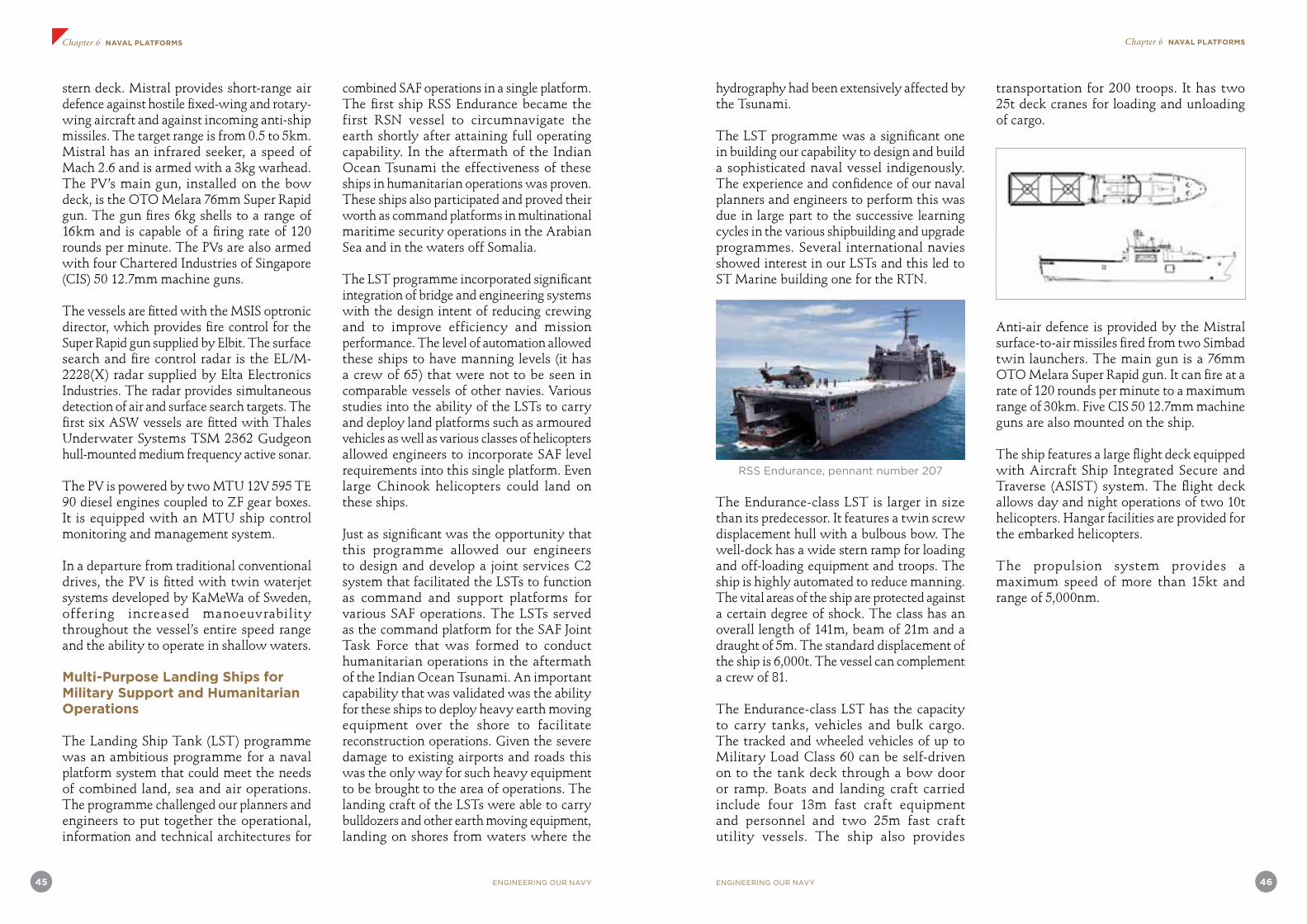
45 ENGINEERING OUR NAVY ENGINEERING OUR NAVY 46
Chapter 6 NAVAL PLATFORMS Chapter 6 NAVAL PLATFORMS
stern deck. Mistral provides short-range air defence against hostile fixed-wing and rotary-wing aircraft and against incoming anti-ship missiles. The target range is from 0.5 to 5km. Mistral has an infrared seeker, a speed of Mach 2.6 and is armed with a 3kg warhead. The PV’s main gun, installed on the bow deck, is the OTO Melara 76mm Super Rapid gun. The gun fires 6kg shells to a range of 16km and is capable of a firing rate of 120 rounds per minute. The PVs are also armed with four Chartered Industries of Singapore (CIS) 50 12.7mm machine guns.
The vessels are fitted with the MSIS optronic director, which provides fire control for the Super Rapid gun supplied by Elbit. The surface search and fire control radar is the EL/M-2228(X) radar supplied by Elta Electronics Industries. The radar provides simultaneous detection of air and surface search targets. The first six ASW vessels are fitted with Thales Underwater Systems TSM 2362 Gudgeon hull-mounted medium frequency active sonar.
The PV is powered by two MTU 12V 595 TE 90 diesel engines coupled to ZF gear boxes. It is equipped with an MTU ship control monitoring and management system.
In a departure from traditional conventional drives, the PV is fitted with twin waterjet systems developed by KaMeWa of Sweden, offering increased manoeuvrability throughout the vessel’s entire speed range and the ability to operate in shallow waters.
Multi-Purpose Landing Ships for Military Support and Humanitarian Operations
The Landing Ship Tank (LST) programme was an ambitious programme for a naval platform system that could meet the needs of combined land, sea and air operations. The programme challenged our planners and engineers to put together the operational, information and technical architectures for
combined SAF operations in a single platform. The first ship RSS Endurance became the first RSN vessel to circumnavigate the earth shortly after attaining full operating capability. In the aftermath of the Indian Ocean Tsunami the effectiveness of these ships in humanitarian operations was proven. These ships also participated and proved their worth as command platforms in multinational maritime security operations in the Arabian Sea and in the waters off Somalia.
The LST programme incorporated significant integration of bridge and engineering systems with the design intent of reducing crewing and to improve efficiency and mission performance. The level of automation allowed these ships to have manning levels (it has a crew of 65) that were not to be seen in comparable vessels of other navies. Various studies into the ability of the LSTs to carry and deploy land platforms such as armoured vehicles as well as various classes of helicopters allowed engineers to incorporate SAF level requirements into this single platform. Even large Chinook helicopters could land on these ships.
Just as significant was the opportunity that this programme allowed our engineers to design and develop a joint services C2 system that facilitated the LSTs to function as command and support platforms for various SAF operations. The LSTs served as the command platform for the SAF Joint Task Force that was formed to conduct humanitarian operations in the aftermath of the Indian Ocean Tsunami. An important capability that was validated was the ability for these ships to deploy heavy earth moving equipment over the shore to facilitate reconstruction operations. Given the severe damage to existing airports and roads this was the only way for such heavy equipment to be brought to the area of operations. The landing craft of the LSTs were able to carry bulldozers and other earth moving equipment, landing on shores from waters where the
hydrography had been extensively affected by the Tsunami.
The LST programme was a significant one in building our capability to design and build a sophisticated naval vessel indigenously. The experience and confidence of our naval planners and engineers to perform this was due in large part to the successive learning cycles in the various shipbuilding and upgrade programmes. Several international navies showed interest in our LSTs and this led to ST Marine building one for the RTN.
RSS Endurance, pennant number 207
The Endurance-class LST is larger in size than its predecessor. It features a twin screw displacement hull with a bulbous bow. The well-dock has a wide stern ramp for loading and off-loading equipment and troops. The ship is highly automated to reduce manning. The vital areas of the ship are protected against a certain degree of shock. The class has an overall length of 141m, beam of 21m and a draught of 5m. The standard displacement of the ship is 6,000t. The vessel can complement a crew of 81.
The Endurance-class LST has the capacity to carry tanks, vehicles and bulk cargo. The tracked and wheeled vehicles of up to Military Load Class 60 can be self-driven on to the tank deck through a bow door or ramp. Boats and landing craft carried include four 13m fast craft equipment and personnel and two 25m fast craft utility vessels. The ship also provides
transportation for 200 troops. It has two 25t deck cranes for loading and unloading of cargo.
Anti-air defence is provided by the Mistral surface-to-air missiles fired from two Simbad twin launchers. The main gun is a 76mm OTO Melara Super Rapid gun. It can fire at a rate of 120 rounds per minute to a maximum range of 30km. Five CIS 50 12.7mm machine guns are also mounted on the ship.
The ship features a large flight deck equipped with Aircraft Ship Integrated Secure and Traverse (ASIST) system. The flight deck allows day and night operations of two 10t helicopters. Hangar facilities are provided for the embarked helicopters.
The propulsion system provides a maximum speed of more than 15kt and range of 5,000nm.

47 ENGINEERING OUR NAVY ENGINEERING OUR NAVY 48
Chapter 6 NAVAL PLATFORMS Chapter 6 NAVAL PLATFORMS
The Endurance-class LST was an extremely capable vessel for SAF operations. These were significantly more capable than the County- class LSTs that they were to replace.
COL (Ret) Siow Chee Khiang recounts his service on board both the former and present landing ships of the RSN below:
“Endurance To Endurance”
In 1981 and as a young Midshipman, I tasted my first sea voyage on board a big ship. It was the 8th Midshipman Sea Training Deployment and we sailed aboard Endurance, a County-class LST of WWII vintage to various ports in the region. To a 19-year-old (and a comic buff reading about WWII naval battles), while there were no surface raiders nor U-Boats, it was indeed an adventure worthy of any schoolboy’s dreams. And at all of 100m, the vessel was a huge ‘playground’ at sea. The lady showed her age as vibrations and creaking noises could be felt and heard throughout the ship with each pounding of the waves! Crossing the South China Sea, we had such severe weather that training had to be cancelled. Most of us, besides those that
were suffering from severe sea sickness, felt like babies in a cot as we laid on our bunks amid the heavy rolling and pounding we encountered throughout that day.
There she was. Sitting high and mighty atop the launch way at ST Marine, she beckoned to me, as I stared and started to wonder what I had landed myself into as the Commanding Officer (CO) (designate) of the biggest vessel to date for the RSN! It was sometime in 1998 that I had my first sight of RSS Endurance, the lead ship in a new class of LST the RSN was building to replace the County-class LST. With her high bow’s majestic silhouette, I was both apprehensive and yet amazed that not only was this ship to be my responsibility and command, she was designed and built by
RSS Resolution, pennant number 208
ST Marine, a local company, and managed by DSTA. Flashes of my days on board the County-class Endurance created a sharp contrast to the new Endurance which was to become my obsession for the next five years (as CO Endurance and subsequently as the Squadron CO). At 141m, the vessel was 40% larger and possessed capabilities way beyond what could be found on the County-class ships, including larger and modern Roll On and Roll Off equipment, the biggest helicopter deck and hangers afloat in the RSN, a well dock and extensive vehicular decks. The non-obvious parts of the vessel were even more impressive.
The new RSS Endurance was designed to be operated by only a crew of 65 and consequently was heavily automated. The bridge adopted a cockpit design, and the Integrated Bridge System needed only one crew to access the navigation and communications systems, the Electronic Chart Display and Information System (ECDIS) and other vital systems needed to sail the ship effectively; while the Ship Control, Monitoring and Management System controlled, monitored and managed most of the platforms on board. Various automated systems (including the ASIST system) allowed helicopter operations to be ‘automated’, enhancing safety while reducing the need for more deck crew. The system works by automatically tracking the landing of a helicopter such that upon landing, the helicopter, with an extended probe, is immediately captured by a Rapid Securing Device which, besides securing the helicopter to the deck, also allows the helicopter to be moved into the hangar.
Boat operations were similarly enhanced with compensating systems for the sea states and modern hydraulic system that not only made the work safer and faster, but needed fewer men to launch a greater number of boats. The Well Dock, while not a new concept, introduced new capabilities and enlarged the envelope for projection of both men and
equipment from the ship, besides being our ‘organic’ swimming pool!
Another important aspect of the new Endurance was that it brought all three services of the SAF onto a common platform where synergies in operations were further enhanced and refined. Within days of the 2004 tsunami in Sumatra, RSS Endurance, then an experienced dame of four years, sortied with a full load of men and equipment geared to conduct a Humanitarian and Disaster Relief (HADR) Operation. For the month she was deployed to Meulaboh, Aceh, Indonesia and together with her sister ships RSS Persistence and RSS Endeavour who joined her later, they conducted daily operations to alleviate the hardship and suffering of the local populace.
But this was the future. Meanwhile back in 1998, mixed with both a sense of apprehension as well as thrill of the challenge, together with a magnificent set of pioneer crew, we helped to build, operationalise and finally embarked on a historic round-the-world deployment on 5th May 2000 (RSN 33rd Anniversary), returning home safely on 2nd September 2000. From her launch on 14th March 1998, to her commissioning on 18th March 2000, the pioneer crew had 26 months to help build, conduct the trials and operationalise the ship before sailing on her own for this 121-day odyssey, including transiting both the Panama and Suez canals. In the process, RSS Endurance also became the first ship in the world to use official electronic navigational charts with the ECDIS to circumnavigate the world. The adage, “Be careful what you wish for” (part of the plan for the trip was to validate the ship and systems and we did wish for heavy seas to test all systems!) hit home when we encountered a Sea State 7 storm as we crossed the Pacific Ocean heading for Acapulco in Mexico. As memories dimmed and we added some romance recalling the storm, it was indeed a beast with the ship being tossed about even as all hands went ‘on
One of the old County-class landing ship tanks, designed for
amphibious operations and landing troops and vehicles directly onto a shore.

ENGINEERING OUR NAVY 50
Chapter 6 NAVAL PLATFORMS
49 ENGINEERING OUR NAVY
Chapter 6 NAVAL PLATFORMS
deck’ to best manage the situation. Later I learned that a legend was born, in that a crew actually slept through the storm!
Another ‘highlight’ was when an engine decided to shut down as we manoeuvred into the Miraflores Lock and with some superb ship handling by the pilot and much calm and cool from the crew, we managed! While undesired, such are the trials and tribulations of any new platform and all that we managed to do can be attributed to the excellent set of pioneer crew. Averaging 25 years, the crew went about their daily work with great enthusiasm and despite being on a new platform with much to assimilate and learn, their fantastic spirits and boundless energies allowed us to overcome all challenges and achieve much on behalf of the navy we all love.
The four LSTs of the Endurance-class went on to serve the RSN well, with deployments to the Persian Gulf (2003, 2004 and 2006) and off the Somalia Coast (from 2009) for peacekeeping and counter-piracy operations and numerous other major exercises and HADR operations. We can all take pride in the achievements of these fine vessels – conceptualised, designed, built, and operationalised by many Singaporeans coming from our local industry (ST Marine), DSTA and the many men and women from the RSN and her sister services from the Singapore Army and the RSAF. While many will remain nameless, it is this combined spirit and great sense of purpose that collectively we can achieve, which will continue to propel our beloved ‘Red Dot’ Onwards and Upwards!
Acquiring a New Principal Strike Craft for Seaward Defence and Safeguarding Our Sea Lanes
In studying the options for the replacement of the MGBs, our planners and engineers challenged their own notions – that our human resource constraints meant that we were only able to crew and operate small naval surface combatants effectively. The LST programme showed that automation through technology could significantly reduce the crewing requirements while maintaining mission capability. Operational experience also indicated that small vessels lacked the ability to conduct sustained autonomous operations at long distances from shore – the very elements necessary to exploit the full strategic advantage of sea power. Small surface combatants operating in the littorals were also limited to a defensive posture as they lacked the ability to carry sensors and weapons to dominate their operating areas effectively above, on and below the sea. Extensive studies, operational analysis and the application of cutting-edge technologies resulted in the requirements definition for the RSN stealth frigate and the eventual acquisition of six frigates to replace the MGBs in the role of principal naval combatants for the RSN.
A very distinctive feature of the Formidable-class frigate was the multi-function radar developed by Thales to the specifications of our planners and engineers. A later version of this radar was later deployed on the Aquitaine-class frigates of the French Navy.
To facilitate the RSN’s participation in peace-support missions, DSTA was approached to equip the frigate with a Launch and Recovery System (LARS) to deploy two water craft. With a touch of inspiration, the DSTA team delivered the first unconventional LARS in July 2012 and completed the harbour trial for the second system in February 2013.
With limited space on the frigate, the only viable location to install the LARS was the Surface-to-Surface Missile (SSM) deck. A large section of the bulwark had to be removed for the LARS to launch the craft onto the sea via the side of the vessel. Without this feature, it would compromise the combat capability and stealth of the frigate, forcing the DSTA team to think out of the box for a creative solution. The team modified the design of a conventional davit successfully, making it compact, collapsible and capable of being launched over the bulwark.
In addition, the team equipped the LARS with both automated and manual operations, making it easier for operators to manoeuvre through the small footprint of the SSM deck. With the automated operation, reliance on the crew’s skills and judgement is reduced. This innovation has enhanced the safety and precision of operators without compromising the stealth and capability of the frigate.
RSS Formidable, pennant number 68
Article credit: DSTA
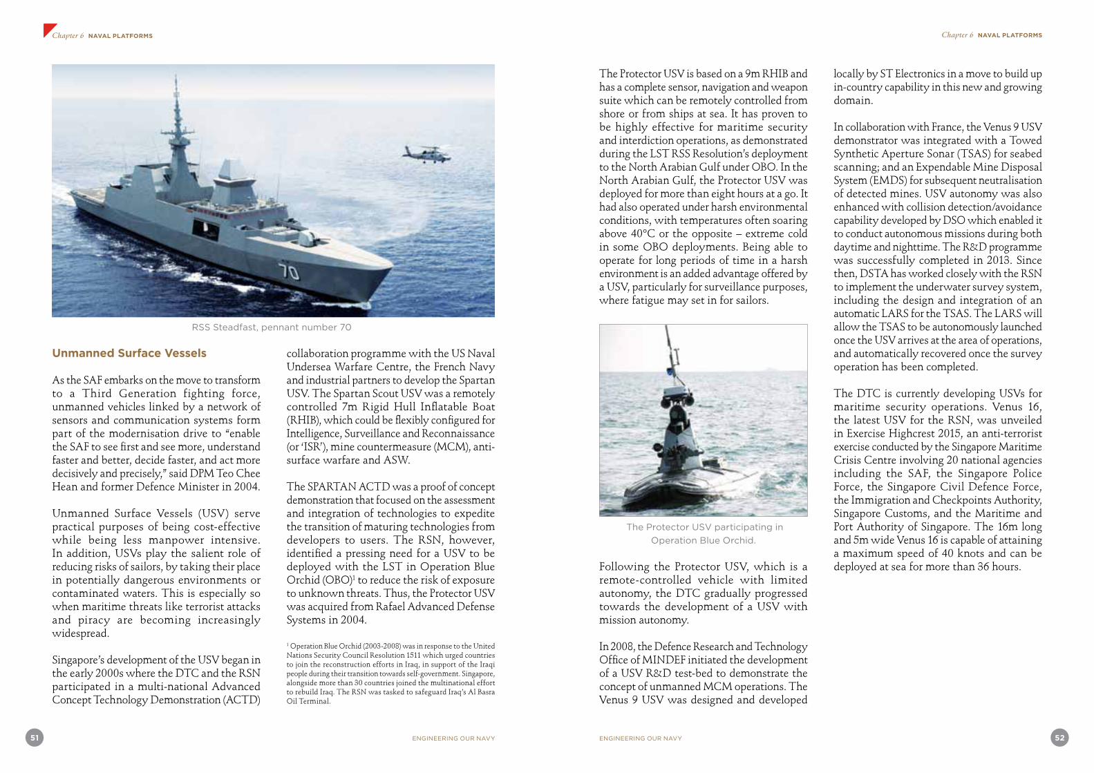
51 ENGINEERING OUR NAVY ENGINEERING OUR NAVY 52
Chapter 6 NAVAL PLATFORMS Chapter 6 NAVAL PLATFORMS
1 Operation Blue Orchid (2003-2008) was in response to the United Nations Security Council Resolution 1511 which urged countries to join the reconstruction efforts in Iraq, in support of the Iraqi people during their transition towards self-government. Singapore, alongside more than 30 countries joined the multinational effort to rebuild Iraq. The RSN was tasked to safeguard Iraq’s Al Basra Oil Terminal.
Unmanned Surface Vessels
As the SAF embarks on the move to transform to a Third Generation fighting force, unmanned vehicles linked by a network of sensors and communication systems form part of the modernisation drive to “enable the SAF to see first and see more, understand faster and better, decide faster, and act more decisively and precisely,” said DPM Teo Chee Hean and former Defence Minister in 2004.
Unmanned Surface Vessels (USV) serve practical purposes of being cost-effective while being less manpower intensive. In addition, USVs play the salient role of reducing risks of sailors, by taking their place in potentially dangerous environments or contaminated waters. This is especially so when maritime threats like terrorist attacks and piracy are becoming increasingly widespread.
Singapore’s development of the USV began in the early 2000s where the DTC and the RSN participated in a multi-national Advanced Concept Technology Demonstration (ACTD)
collaboration programme with the US Naval Undersea Warfare Centre, the French Navy and industrial partners to develop the Spartan USV. The Spartan Scout USV was a remotely controlled 7m Rigid Hull Inflatable Boat (RHIB), which could be flexibly configured for Intelligence, Surveillance and Reconnaissance (or ‘ISR’), mine countermeasure (MCM), anti-surface warfare and ASW.
The SPARTAN ACTD was a proof of concept demonstration that focused on the assessment and integration of technologies to expedite the transition of maturing technologies from developers to users. The RSN, however, identified a pressing need for a USV to be deployed with the LST in Operation Blue Orchid (OBO)1 to reduce the risk of exposure to unknown threats. Thus, the Protector USV was acquired from Rafael Advanced Defense Systems in 2004.
RSS Steadfast, pennant number 70
The Protector USV is based on a 9m RHIB and has a complete sensor, navigation and weapon suite which can be remotely controlled from shore or from ships at sea. It has proven to be highly effective for maritime security and interdiction operations, as demonstrated during the LST RSS Resolution’s deployment to the North Arabian Gulf under OBO. In the North Arabian Gulf, the Protector USV was deployed for more than eight hours at a go. It had also operated under harsh environmental conditions, with temperatures often soaring above 40ºC or the opposite – extreme cold in some OBO deployments. Being able to operate for long periods of time in a harsh environment is an added advantage offered by a USV, particularly for surveillance purposes, where fatigue may set in for sailors.
The Protector USV participating in
Operation Blue Orchid.
Following the Protector USV, which is a remote-controlled vehicle with limited autonomy, the DTC gradually progressed towards the development of a USV with mission autonomy.
In 2008, the Defence Research and Technology Office of MINDEF initiated the development of a USV R&D test-bed to demonstrate the concept of unmanned MCM operations. The Venus 9 USV was designed and developed
locally by ST Electronics in a move to build up in-country capability in this new and growing domain.
In collaboration with France, the Venus 9 USV demonstrator was integrated with a Towed Synthetic Aperture Sonar (TSAS) for seabed scanning; and an Expendable Mine Disposal System (EMDS) for subsequent neutralisation of detected mines. USV autonomy was also enhanced with collision detection/avoidance capability developed by DSO which enabled it to conduct autonomous missions during both daytime and nighttime. The R&D programme was successfully completed in 2013. Since then, DSTA has worked closely with the RSN to implement the underwater survey system, including the design and integration of an automatic LARS for the TSAS. The LARS will allow the TSAS to be autonomously launched once the USV arrives at the area of operations, and automatically recovered once the survey operation has been completed.
The DTC is currently developing USVs for maritime security operations. Venus 16, the latest USV for the RSN, was unveiled in Exercise Highcrest 2015, an anti-terrorist exercise conducted by the Singapore Maritime Crisis Centre involving 20 national agencies including the SAF, the Singapore Police Force, the Singapore Civil Defence Force, the Immigration and Checkpoints Authority, Singapore Customs, and the Maritime and Port Authority of Singapore. The 16m long and 5m wide Venus 16 is capable of attaining a maximum speed of 40 knots and can be deployed at sea for more than 36 hours.

53 ENGINEERING OUR NAVY ENGINEERING OUR NAVY 54
Chapter 6 NAVAL PLATFORMS Chapter 6 NAVAL PLATFORMS
DEVELOPMENT OF USV CAPABILITY OVER THE YEARS
Year
2004 2006 2008 2010 2012 2014 2016
Capability
9m Protector USV
Collision Detection/Avoidance (CDCA) development
MCM USV development
Experimental USV for T&E of autonomy functions
Mission autonomy, collision avoidance
capability
Remote-control, limited autonomy,
no collision avoidance
The Venus 16 USV, performing in
Exercise Highcrest.
RADM Frederick Chew Chih Chiang, Commander of the Maritime Security Task Force said, during an interview at Exercise Highcrest, that “unmanned technologies can help to complement manned platforms. Instead of one or two patrol vehicles that can influence only their immediate surroundings, unmanned surface vessels can protect a larger area around the Singapore Strait.” With their distinct advantage of operating without personnel on the frontline, the USVs act as force multipliers to perform useful surveillance and presence roles.
The Engineering Resource Lab (ERL) is developed by DSTA’s Naval Systems Programme Centre and comprises a sophisticated suite of software and computational tools for Ship Performance Analysis, Integrated Topside Design, Sensors and Weapons Integration, as well as Underwater Performance Analysis.
With the aid of these specialised engineering tools, DSTA engineers can perform engineering and trade-off studies, propose design concepts and options, and review systems design. They are also able to analyse performance data and validate measurements and test results of integrated systems more efficiently with shorter time spans.
A team from the Naval Systems Programme Centre clinched the National Innovation and Quality Circle Gold Award in 2012 for their innovative use of the tools in the ERL to boost productivity and address technical challenges.
Article credit: DSTA
The development of USV capability over the years
Naval Platform Technology Expertise Development
In supporting the wide-ranging missions of the RSN platforms, our engineers and scientists developed deep expertise in various domain areas such as C2, weapons, electronic warfare, underwater acoustics, mitigating the effects of underwater explosions, system reliability and resilience and submarine safety and rescue. These deep expertise is distributed among the elements of the defence technology ecosystem including DSO, DSTA, ST Engineering and R&D expertise in the universities and research institutions.
Managing Complex Upgrading Projects for Naval Platforms
Service Life Extension and upgrading of naval platforms is a core competency of our naval engineers. The following narrative by DSTA engineers Goh Yong Han and Lam Su Ying Audrey on the upgrading of the RSN mine countermeasure vessels (MCMV) is illustrative of the expertise acquired by our engineers in successfully undertaking an upgrade project with a very lean project management team.
The RSN’s four Bedok-class MCMVs were acquired from Sweden and commissioned in 1995. In view of their ageing systems and the advent of new technologies, DSTA embarked on a modernisation programme for the MCMVs. This programme commenced in 2009 with the installation of an advanced and integrated mine countermeasure combat system, comprising a Mine Information System, Hull Mounted Mine Hunting Sonar (MHS), TSAS and an EMDS.
The conventional approach to managing a Life Extension Programme (LEP) of a naval vessel of such complexity is to form a core integrated Project Management Team (PMT) of more than 10 engineers to oversee major combat, platform and shore systems. The PMT adopted a prime contractor approach
to minimise the size of the team after a careful study. The prime contractor supplied the majority of the systems, installed and integrated them with existing systems, and was responsible for the performance of the total system. This allowed a core PMT of half the typical size to manage the entire LEP.
RSS Punggol, pennant number M108
The K-STER EMDS uses a shaped charge
to detonate suspected mines.
RSS Kallang, pennant number M106,
sailing to help in the search for Indonesia
AirAsia flight 8501, as part of
the Underwater Search Task Group.

55 ENGINEERING OUR NAVY ENGINEERING OUR NAVY 56
Chapter 6 NAVAL PLATFORMS Chapter 6 NAVAL PLATFORMS
Managing Developmental Items during Contracting
During the tender exercise in 2008, all submitted proposals had some key systems that were still in the high risk development phase due to the demanding technical performance specifications of the tender. By applying the procurement principles of competition and value for money, the PMT employed competitive bidding exercises and included contractual clauses to protect the SAF’s interests in the event of possible failure of the developmental systems. This ensured the tender returns would be cost-effective, with acceptable risk management measures put in place by each of the tenderers.
Achieving Cost Effectiveness during Contracting
The PMT had originally mandated all tenderers to engage the original designer of the MCMV as the platform consultant to oversee the platform modification works as a risk mitigation measure. Subsequently, the PMT conducted a thorough technical risk assessment and explored engaging an alternate platform consultant with the tenderers to achieve greater cost effectiveness. The PMT conducted detailed ship surveys on each MCMV, reviewed the existing documentation and drawings, and determined that minimal platform modifications were required. All required information could also be obtained through measurements. By systematically going through the risks of modification and integration, the PMT selected an alternate platform consultant with experience in managing MCMV platform upgrading and achieved further cost savings. With the added risk assessment and management processes put in place contractually and through project milestone review meetings and progressive monitoring, this approach led to the effective and successful execution of the programme.
Managing Integration Risk with Legacy Systems
The delivery of the upgraded programme capability was heavily dependent on the successful integration of the existing systems with the new systems. This is a more complex task compared to newly built programmes as some of the information required for integration is not available for some legacy systems. To mitigate this risk, pre-condition assessments (PCA) were performed to establish and record the baseline configuration of the ship through a series of inspections and tests. This enabled the reconstruction and extraction of missing information. At the same time, the PCA served to verify the legacy systems’ performance and interface specifications to facilitate integration with the new systems.
Delivering Improved Mine Hunting Capability
Underwater mines are located using sonar which is traditionally a slow and tedious process. With the advent of new technologies, for example the SAS, mine hunting can be performed better and faster. The principle of SAS is to combine successive pings along a known track coherently in order to increase the resolution of the azimuth direction (along-track). Hansen (2011) explained that with this increased “synthetic aperture” length, the sonar is able to obtain higher resolution images with respect to conventional sonar processing. The coverage rate for a TSAS is about five times faster than the legacy hull-mounted MHS. This is achieved due to a higher survey speed and wider sonar swath widths. Being hull-mounted, the one-sided MHS array limits the MCMV speed during survey, while the TSAS is a two-sided array able to cover more area, and can be towed at a higher speed to achieve a much higher coverage rate. In addition, the TSAS provides significantly higher resolution for improved classification capability. The new TSAS also
offers an automatic detection and classification capability to ease the operator’s workload in mine detection and classification.
Compared to the previous sonar system which was hull-mounted and not towed, the PMT conducted an extensive safety review on the procedures provided by the contractors for the launching, recovery and towing operations. All the emergency safety features of the TSAS, such as emergency surfacing, cable breaking tensions and emergency stops, were individually analysed during design reviews and tested thoroughly during sea acceptance tests to ensure safe operations. The launch and recovery procedures were also improved and simplified through numerous sea trials.
Delivering Improved Mine Neutralisation Capability
The Mine Disposal System (MDS) has been used by the RSN for mine neutralisation since 1995. The vehicle used in the MDS weighs about 900kg and requires a crane and handling system for launching and recovery during mine neutralisation missions. As part of the MCMV modernisation programme, a new EMDS was acquired and installed on board the MCMVs. The K-STER EMDS is capable of identifying and neutralising mine-like objects to support the mine clearance operations of the RSN. It is a remotely operated vehicle that consists of a lightweight vehicle and supporting shipboard systems. The vehicle has two configurations – the K-STER Inspection for identification of mine threats, and the K-STER Combat for neutralisation of mines. The expendable K-STER Combat vehicle is designed to neutralise a mine with a single shot. This vehicle has led to vast improvements in mission effectiveness as it is lightweight, simple to operate and easy to deploy. At 50kg, it is less than 10% the weight of the previous MDS vehicle, and its lighter weight simplifies the launch and recovery process. It is estimated that the operation time per mine is reduced by about half.
Equipped with just a small charge, the vehicle is designed with a tiltable warhead, sonar, sighting laser, video camera and searchlights to locate and attack mines accurately and efficiently. The K-STER Combat vehicles are stored in the EMDS magazine on board the MCMVs. To minimise manual handling of vehicles, the PMT worked closely with the prime contractor to design a set of customised jibs and fixtures to facilitate a more efficient transfer of K-STER Combat vehicles.
The RSN is the first navy in the world to conduct live-firing using this vehicle. As this is a new weapon system, there were no previous firing templates or references. The PMT collaborated with the RSN to develop test scenarios and safety firing templates. Subsequently, with the knowledge gained from the first firing, the PMT worked out a new weapon danger area template which significantly reduced the safety radius compared to the first firing. This achieved further cost savings in terms of assets and time required for safety clearance. In addition, over the several sea trials and live-firing, the PMT enhanced the preparation procedures progressively, and implemented additional instrumentation to further automate the pre-launch process. These served to reduce the preparation time needed before each firing.
Through the application of sound system engineering, the PMT successfully completed the MCMV modernisation programme for the RSN in 2014 in a cost-effective manner. This has resulted in new and enhanced mine countermeasure capabilities to keep Singapore’s sea lanes mine-free and safe.
Acquiring, Supporting and Upgrading Pre-Owned Naval Platforms
The acquisition of a submarine capability for the RSN illustrates a pragmatic and cost-effective approach in building a new

57 ENGINEERING OUR NAVY ENGINEERING OUR NAVY 58
Chapter 6 NAVAL PLATFORMS Chapter 6 NAVAL PLATFORMS
capability. Submarines are very sophisticated vessels and the RSN did not have operating experience to adequately specify what it needed. An opportunity arose when the Royal Swedish Navy was to phase out its Sjoormen-class submarines. This presented an excellent opportunity to build up a new capability for the RSN through the acquisition of these vessels including arrangements for both the RSN and our defence engineers to acquire the operational and technical knowledge through training by the Royal Swedish Navy.
In the submarine acquisition programme, two significant aspects of engineering and maintenance practices should be highlighted here – the first being the implementation of the Submarine Maintenance and Safety Programme (SMSP). The RSN has adopted the SUBSAFE programme from the US Navy on the Challenger-class submarines. It is to provide a high assurance for watertight integrity of the boat and, at the same time should flooding occur, the ability for the boat to recover and surface. The RSN has made some changes to the US Navy system by including the electrical and high pressure systems into the SMSP to make the safety framework more comprehensive. This is a unique requirement for the submarine as no surface warship in the RSN has such demanding engineering, maintenance and document requirements. They are almost like aircraft requirements to ensure traceability in material and workmanship. The RSN had to conduct training for the shipyards so that they can comply with the SUBSAFE requirements. Regular audit on the work processes and material control were conducted by the RSN to ensure compliance.
Second, as these submarines were of Swedish origin designed for the brackish waters and cold weather of Sweden, major modifications to the piping system, sea water system and ventilation system were carried out. Different material and design were used and installed to enable these boats to work in our high
temperature, high humidity and high salinity environment.
This programme provided our engineers with significant lessons on the challenges in acquiring and supporting the operations of pre-owned naval platforms. The following narrative by DSTA engineers Cheah Yew Jin, Ong Li Koon and Tan Beng Hock illustrates the learning experience in such programmes.
Lessons Learnt from Managing Acquisition of Pre-Owned Naval Platforms
Acquisition of pre-owned military platforms can be a cost-effective solution to meet operational requirements but it also poses significant challenges.
While these issues can be partially mitigated through a well-crafted contract and close supervision during the acquisition, the challenge comes in handling the unexpected and resolving them swiftly in order not to impact the project schedule adversely. Our engineers provide some insight into the challenges faced and suggest measures that can be used to refine the existing framework for the acquisition of pre-owned platforms.
Pre-owned military platforms are opportunity buys that can be brought into service rapidly and cost effectively. Compared to the long lead time required to design, build and test new military platforms, pre-owned platforms typically only require country specific modifications and refurbishment and therefore can be inducted into service in a short time. Such acquisitions are not new to the SAF. Pre-owned platforms such as the County-class LSTs, AMX13 light tanks and A4 Skyhawks allowed the SAF to build up military capabilities which were required urgently in its formative years, in a quick and cost-effective manner. While the SAF has evolved over the years and many new systems have been acquired, the advantage offered
by opportune pre-owned military platforms has not been completely dismissed. This is clearly demonstrated by the acquisition of the Challenger-class submarines as well as the Leopard 2 tanks. Our engineers know there is a wealth of experience in the realm of acquiring pre-owned platforms, and many project teams have since drawn on this knowledge.
Framework for Acquiring Defence Systems
Over the years, the MINDEF has developed a structured approach to manage the life cycle of defence systems. The framework (MINDEF, 2012) serves to guide the management of systems through the system’s life cycle, beyond just the acquisition phase. It has been useful in the management of new systems and capabilities.
While the process for the acquisition of new build military platforms is well defined and the challenges understood, the same cannot be said of the acquisition of pre-owned military platforms. Being opportunistic buys, such acquisition projects of pre-owned platforms
tend to be ad hoc purchases, and have unique project management and technical challenges. As such, the existing framework can be adapted to better reflect the unique challenges of such acquisitions.
Unique Challenges in Acquisition of Pre-owned Platforms
Time pressure to conclude opportunistic acquisitions usually leaves the project team with little time to examine the state of the component systems on board the platforms thoroughly and properly, look out for defects or to validate the prevailing performance of the systems before contractual commitment. Without in-depth system knowledge, the project team will also face difficulty in specifying the modification and upgrades required to customise the platform for the new intended usage.
Dealing with Uncertainty in Material Condition
Normally, the material condition of pre-owned platforms cannot be fully ascertained prior to acquisition as it is not possible to
The life cycle management process
Life Cycle Key Activities
Long-Term Planning Strategic planning, formulation of concepts and master plans, resource prioritisation
Front-End Planning System requirements planning, project planning, management and control
Acquisition Management System definition, tender management, contract award, engineering development management, serial production management
Transition to O&S Acceptance, delivery, system run-in, post implementation reporting
O&S Management System management, training and personnel development, real estate management, operational test and evaluation, system modification, system upgrade, budget management
System Retirement Retirement planning, logistics support planning, sales planning and approach

59 ENGINEERING OUR NAVY ENGINEERING OUR NAVY 60
Chapter 6 NAVAL PLATFORMS Chapter 6 NAVAL PLATFORMS
strip the entire platform down to its component level. As it is impractical and too costly to order a complete overhaul and renewal of every component, it is not unusual to adopt the existing refurbishment scope of work of the host country since the project team may not be equipped with sufficient knowledge to specify the required scope of refurbishment accurately.
However, adopting the existing maintenance scope of work is inadequate. It is not unusual for the existing owner to drop selective scope of work for overhaul to manage cost and availability. This is usually an acceptable practice for the existing owner since the platform’s original equipment manufacturer (OEM) is able to provide timely support when defects occur due to their close proximity with their armed forces. The same would probably not be valid for the new owners of the pre-owned platforms as the OEM is most likely located at extended distances and thus unable to provide the required repair at short notice. In this case, there is a need to perform the additional overhaul scope of work not normally performed during the refurbishment, especially for safety critical systems, to mitigate potential future availability issues due to component failure. The additional scope of work would be next to impossible to establish at such short notice under a normal contract situation.
Poor material conditions are picked up typically through close supervision of the refurbishment process. The presence of an on-site supervision team, otherwise known as the Resident Programme Office, enables the prompt identification of defects over the course of the refurbishment phase and helps to mitigate potential schedule delays. In addition, the availability of a fast-track process will greatly facilitate the project team’s engagement with the OEM to resolve issues expeditiously. The boundaries of such a fast-track process would have to be defined during the acquisition management
phase of the system’s life cycle.
Handling Existing Systems
Besides being unable to ascertain the exact material conditions of existing components, the project team would also likely be hard-pressed to provide the detailed modification and upgrade required to convert the pre-owned platforms to suit local needs due to insufficient system knowledge. Likely shortfalls will occur in areas such as adaptation to local conditions (different environmental conditions), safety (due to differing workflows and safety tolerances), monitoring system (different operating philosophies), host country laws and regulations. Additional modifications not included within the original scope of work will likely incur substantial cost and adversely impact the schedule especially if identified late in the project management when design has been finalised. To mitigate such issues, a checklist of potential modifications would be helpful. Such a list would be accumulated over time drawing from the lessons learnt from similar projects. The applicability and critical level of each lesson would have to be assessed during the front-end planning phase.
Another likely issue on existing systems relates to the performance of the pre-owned platform and the onboard system. While the refurbishment and upgrade would have rejuvenated and extended the service life of the pre-owned platforms, it is not realistic to expect the pre-owned platform and the onboard system to perform to the originally specified performance. This is especially so for electromechanical systems. In the event where the existing or modified system fails to meet specific performance requirements, disputes would arise between the OEM and the project team on the acceptability of the performance demonstrated and whether additional modification would be required
to improve the performance. The resulting cost and impact on schedule would be another point of contention.
To handle such issues, it is important to provide acceptable tolerance to handle the likely deterioration of performance due to ageing as well as a mechanism in the contract to handle the liability and responsibility in the event of such an occurrence. The mechanism should include cost-sharing formulae to handle situations where additional modifications of existing systems are required. Such a mechanism would have to be proposed during the acquisition management phase to gain the OEM’s acceptance on the cost-sharing approach prior to contract signing.
Configuration Management Challenges
Over the course of the project, it is not uncommon to note discrepancies between the documented information and the physical configuration found on board the platforms. The most common observations are missing components, from items as minor as cable tags to major items like sub-assemblies as well as the mismatch between the actual component and its description as stated in the technical manuals (e.g. normal nuts were used instead of self-locking nuts). It is common to discover additional components fitted but not reflected in drawings (typical items are electrical sockets and storage boxes) as well as electrical connections in the drawings differing from physical connections on board. It is also possible to note discrepancies in configuration between different platforms of the same class (such as additional structural fittings, elbows and extensions on various piping). Ad hoc corrective actions will be required to manage such discrepancies or to document the non-conformity.
Other than inaccurate configuration, it is also likely that the text on the labels, tags, gauges, instructions and warning signs are written in the language of the host country.
Such a configuration could pose a dilemma. Enforcing blanket changes to English text would likely incur a substantial cost, bearing in mind that the related documentation such as drawings and technical manuals will need to be updated as well. In many cases, trade-offs will be necessary to achieve the right balance between operational efficiency/safety and cost effectiveness. Based on experience, all text with safety implications (such as warning signs, operational instructions and push buttons) should be replaced to reduce the likelihood of human error during operations. This would have to be imposed on the OEM during the acquisition management phase.
Unfortunately, it is impractical and impossible to identify all the text that needs to be changed at contract signing. Hence, the remaining configuration issues would have to be resolved during the project implementation.
Since many configuration issues cannot be fully anticipated, it is necessary to set aside adequate budget to update the configuration to reflect actual conditions, and without compromising safety.
Dealing with Obsolescence
Equipment obsolescence is a key requirement that must be addressed to ensure supportability and maintainability post-delivery. This is especially critical when the pre-owned platforms are expected to be supported for an additional service life of greater than 10 years. It is important to demand that the OEM provide evidence during the acquisition management phase to identify potential obsolescence issues upfront. It is also important to continue to keep a close watch during the refurbishment or upgrade to identify further occurrences of potential obsolescence and resolve them promptly. Solutions to overcome obsolescence include acquiring the remaining spares, contracting the OEM for an extended maintenance agreement or warranty, sourcing third-party maintenance and supply support,

61 ENGINEERING OUR NAVY ENGINEERING OUR NAVY 62
Chapter 6 NAVAL PLATFORMS Chapter 6 NAVAL PLATFORMS
and re-designing, replacing or upgrading the existing components or system.
To mitigate potential schedule delay, it is necessary to purchase the remaining available spares to ensure at least short-term supportability while efforts are taken to review the feasibility of the other solutions to obsolescence. Redesign and upgrade of obsolete components/systems are usually undertaken after a proper cost-effectiveness study is conducted since it will typically incur substantial cost and impact on schedule. Nevertheless, re-designing, replacing or upgrading existing components may be necessary during the course of the project implementation and it will therefore be important to address, if possible, how to manage such obsolescence issues in the contract.
Implementing New Systems
To meet the operational demands, there could be requirements to implement and integrate new systems to the pre-owned platforms. This is especially true for combat systems which typically need to be replaced in order to meet unique operational demands or to manage obsolescence due to rapid advancement of technology. The typical problem associated with implementation of new systems, especially electronic systems, relates to the compatibility of the new systems with the existing services and support systems such as electrical power supply, hydraulic system and cooling system. In many cases, there may be insufficient electrical power, cooling capacity or hydraulic supply to support the system or the quality of the power supply may not meet the demands of the new electronic systems. The existing foundation may also be incompatible and require redesign. Therefore it is necessary to factor in the required upgrade to the foundation, the power supply and the supporting systems during the front-end planning phase to prevent costly modifications late in the projects.
Managing Differences in Standards
Due to differences in the design standards between the pre-owned platform and the new systems such as electromagnetic compatibility and/or quality of power supply, issues such as interference and performance degradation can arise. To mitigate such issues, it is important to ensure that the new systems to be installed are sufficiently robust so that they do not become a source of interference or become affected by the existing equipment or system. However, such issues are difficult to identify beforehand and it is therefore necessary to cater for interoperability tests. This is to check for equipment interference so that corrective actions can be taken promptly.
For pre-owned platforms, the safety standards that were adopted back then to design the platform could be legacy standards that are probably obsolete and/or superseded by newer and more stringent standards. Therefore, efforts may be required to ascertain the gap between the legacy standards and the new benchmarks in areas such as explosives, system and workplace or occupational safety in order to identify corrective actions that can be implemented during the project phase. Such efforts have to be undertaken in the early phase of the project in order to prevent excessive cost and impact on schedule as a result of last minute modifications. In some instances, there may be no viable solutions available and residual risks will have to be managed via procedures.
Managing Documentation
Similar to the configuration issue, much existing documentation would have been written in the language of the host country. Concise and precise translation of the documentation will be necessary to ensure effective operation and support in the future. Such translation may not impact the project schedule but is nevertheless a costly affair
which needs to be budgeted adequately.
Building Relationships with Host-country Armed Forces
With acquisition of pre-owned platforms involving two countries, it is pertinent to foster good relationships between the armed forces of both countries to promote the sharing of experiences and lessons learnt. In many cases, support like trial assets and safety clearances from the host country’s armed forces would also be required during the acceptance trials for the pre-owned platforms. Interactions between the armed forces would also improve understanding of each other’s culture and facilitate planning and discussions during the testing phase.
Refining the Existing Framework
Drawing from the lessons learnt, it can be seen that the existing framework would need to be adapted to better serve the needs of managing the acquisition of pre-owned military platforms.
While these insights were derived largely from the experience of acquisition management of pre-owned naval platforms, the lessons learnt and the proposed adaptations to the acquisition framework are applicable to pre-owned land or air platforms as well. Awareness of past lessons learnt will help shorten the learning curve, placing project teams in a better position to handle the unexpected and resolve challenges swiftly to deliver capabilities to the SAF in good time.
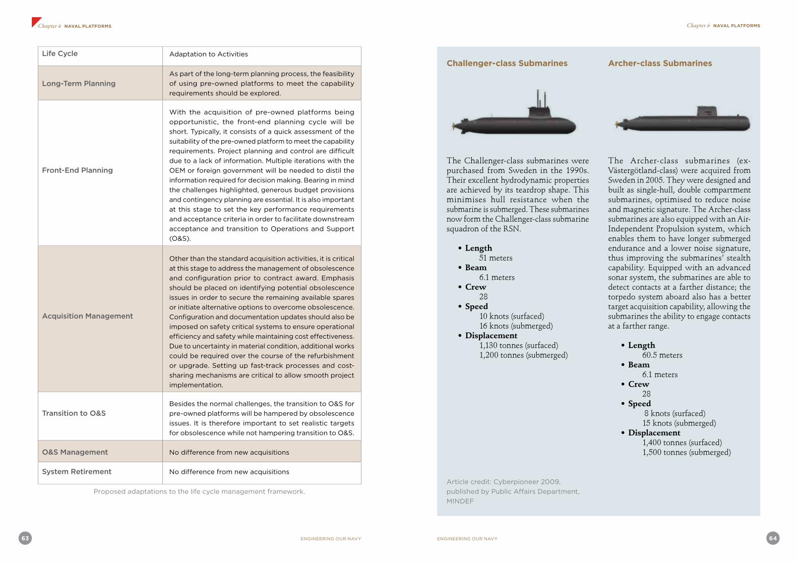
63 ENGINEERING OUR NAVY ENGINEERING OUR NAVY 64
Chapter 6 NAVAL PLATFORMS Chapter 6 NAVAL PLATFORMS
Life Cycle Adaptation to Activities
Long-Term PlanningAs part of the long-term planning process, the feasibility
of using pre-owned platforms to meet the capability
requirements should be explored.
Front-End Planning
With the acquisition of pre-owned platforms being
opportunistic, the front-end planning cycle will be
short. Typically, it consists of a quick assessment of the
suitability of the pre-owned platform to meet the capability
requirements. Project planning and control are difficult
due to a lack of information. Multiple iterations with the
OEM or foreign government will be needed to distil the
information required for decision making. Bearing in mind
the challenges highlighted, generous budget provisions
and contingency planning are essential. It is also important
at this stage to set the key performance requirements
and acceptance criteria in order to facilitate downstream
acceptance and transition to Operations and Support
(O&S).
Acquisition Management
Other than the standard acquisition activities, it is critical
at this stage to address the management of obsolescence
and configuration prior to contract award. Emphasis
should be placed on identifying potential obsolescence
issues in order to secure the remaining available spares
or initiate alternative options to overcome obsolescence.
Configuration and documentation updates should also be
imposed on safety critical systems to ensure operational
efficiency and safety while maintaining cost effectiveness.
Due to uncertainty in material condition, additional works
could be required over the course of the refurbishment
or upgrade. Setting up fast-track processes and cost-
sharing mechanisms are critical to allow smooth project
implementation.
Transition to O&SBesides the normal challenges, the transition to O&S for
pre-owned platforms will be hampered by obsolescence
issues. It is therefore important to set realistic targets
for obsolescence while not hampering transition to O&S.
O&S Management No difference from new acquisitions
System Retirement No difference from new acquisitions
Proposed adaptations to the life cycle management framework.
Challenger-class Submarines
The Challenger-class submarines were purchased from Sweden in the 1990s. Their excellent hydrodynamic properties are achieved by its teardrop shape. This minimises hull resistance when the submarine is submerged. These submarines now form the Challenger-class submarine squadron of the RSN.
• Length 51 meters• Beam
6.1 meters• Crew
28• Speed
10 knots (surfaced) 16 knots (submerged)• Displacement
1,130 tonnes (surfaced) 1,200 tonnes (submerged)
Archer-class Submarines
The Archer-class submarines (ex-Västergötland-class) were acquired from Sweden in 2005. They were designed and built as single-hull, double compartment submarines, optimised to reduce noise and magnetic signature. The Archer-class submarines are also equipped with an Air-Independent Propulsion system, which enables them to have longer submerged endurance and a lower noise signature, thus improving the submarines’ stealth capability. Equipped with an advanced sonar system, the submarines are able to detect contacts at a farther distance; the torpedo system aboard also has a better target acquisition capability, allowing the submarines the ability to engage contacts at a farther range.
• Length 60.5 meters• Beam 6.1 meters• Crew 28• Speed 8 knots (surfaced) 15 knots (submerged)• Displacement 1,400 tonnes (surfaced) 1,500 tonnes (submerged)
Article credit: Cyberpioneer 2009,
published by Public Affairs Department,
MINDEF

65 ENGINEERING OUR NAVY
Chapter 6 NAVAL PLATFORMS
ENGINEERING OUR NAVY 66
THE ELECTROMAGNETIC BATTLEFIELD
Much of a naval operation above the sea is dependent on the ability to use the electromagnetic spectrum to one’s advantage and to deny its effective use to the adversary. Early naval operations were limited to exploiting only the visible part of the electromagnetic spectrum. With the current sophistication of modern sensors, weapons and their guidance systems, mastery in understanding the workings of the electromagnetic environment is critical to the effective design, development and operations of naval systems.
Always cognizant that the RSN would have to fight outnumbered, naval planners and engineers conducted various one-on-one and force-on-force simulations using various combat scenarios to better understand how the RSN would fare in these scenarios against various adversaries. Many of our engineers and naval officers had received their advanced degrees in the US NPS. Professor Wayne Hughes from NPS, an expert in naval operations analysis, was engaged to help in the establishment of various operations analysis methodologies and tools to facilitate our naval planners and engineers’ work. Less than favourable exchange ratios had to be addressed by having superior tactics and the use of advanced electronic warfare (EW) tools and techniques. Fortunately, the RSN could rely on the EW capabilities that were being built up in the then DSO. It is a tribute to Dr Goh Keng Swee’s foresight that he realised the importance of technologies such as EW, sensors and remote control way back in 1972 when DSO was established.
Project Magpie was a secret codename
Then Deputy Prime Minister and Minister for Defence, Dr Goh Keng Swee, foresaw the need to have a capable military force to protect Singapore and her people. He predicted that warfare in the 21st century would enter the realm of science and technology, with electronic warfare at its heart. With Singapore lacking in strategic geographical depth and a tiny population, Dr Goh envisaged the use of technology as a force multiplier to overcome Singapore’s security challenges.
Project Magpie marked Singapore’s first Research and Development (R&D) efforts in electronic warfare. Amid high security in an obscure premise, three scientists began their first foray into defence R&D – and Singapore’s first defence science laboratory was born. They called it the Electronics Test Centre (ETC). The year was 1972.
It was an arduous journey, but with a determined mindset and commitment to protect Singapore’s security, ETC continued to build up on its research capabilities and development of cutting-edge technologies.
In 1977, it was renamed the Defence Science Organisation.
The company was corporatised as a not-for-profit company in 1997 and became
Chapter Seven
RSS Swordsman, Singapore’s second Archer-class submarine, was commissioned in April 2013. The first submarine, RSS Archer, was commissioned for active service in December 2011.
The Archer-class submarines project was a large-scale, complex naval project that involved the integration of new and old systems. To deliver the Archer-class submarines, the DSTA team played a leading role in upgrading two Västergötland-class submarines to a modern and capable naval platform for the RSN.
The critical upgrade was to modify and adapt the platform systems to host the modern combat systems. Their arrangement, network connectivity, as well as electrical and cooling systems were improved. The submarines were also equipped with an Air-Independent Propulsion system for an extended submerged endurance.
To meet the RSN’s unique requirements, the team oversaw the acquisition and
integration of various combat systems with the existing platform systems on board the submarines. One of the major engineering challenges was to pack all the required mission systems into the tight confines of a submarine, while retaining its ability to operate safely. A diverse suite of combat and sensor systems was integrated into the submarines, including an advanced sonar system which allows them to detect targets at a further distance, and the torpedo system which has a better target acquisition capability for the submarines to engage targets at a longer range.
With an extended submerged endurance, improved combat capabilities and surveillance, the Archer-class submarines represent a leap in capability for the RSN. The team was conferred the prestigious Defence Technology Price 2013 Team (Engineering) Award for its outstanding contributions.
Article credit: DSTA

67 ENGINEERING OUR NAVY ENGINEERING OUR NAVY 68
Chapter 7 THE ELECTROMAGNETIC BATTLEFIELD Chapter 7 THE ELECTROMAGNETIC BATTLEFIELD
as well as at sea. ESM systems and chaff were soon complemented by more electronic countermeasure equipment such as jamming systems to provide more effective defence against newer anti-ship missiles.
In the late 1970s, a major learning opportunity came when the RSN acquired ESM and chaff systems for their MGB. The ESM and chaff systems together formed an EW system for the MGB, protecting it against threats such as missiles. The ESM is a radio receiver system which listens for and identifies radio signals emitted by a missile radar seeker during an attack. On confirmation of an attack, it activates the ship’s defence by launching chaff, which is basically a physical decoy made of a cloud of metallic strips of various lengths designed to confuse the radar seeker systems of the threat missiles.
A key challenge then was to develop chaff technique against such threats, which involved the analysis and deployment of chaff as an effective target to lure the missile away from its intended target. Modelling and simulation provided important insights into the dynamics and complexity of this multi-faceted problem. The DSO engineers needed to understand chaff in terms of a cloud of dipoles acting as an effective radio wave “reflector” and how its effectiveness could be complicated by the effects of environment and the behaviour of radar. For example, it was necessary to know how a missile radar seeker views an area of interest and how it selectively accepts only the relevant signals of interest.
“RSN crew became more confident of their equipment, training and tactical capabilities. With a small number of
highly capable platforms they were confident of defeating an adversary force with larger numbers of platforms. An RSN recruitment commercial entitled “Did anyone order a missile” depicted how RSN crew could spring into action to defeat an incoming missile attack and then deploy shipboard weapons to defeat the enemy.”
Source: DSO
Initially, the guidance systems of anti-ship missiles were not that sophisticated and could be fooled by well-executed EW techniques. However, as missiles became more sophisticated and enhanced with electronic counter-counter measure capabilities as well as with seekers that operated in more than one part of the electromagnetic spectrum, soft-kill defence was no longer fully effective. Fortunately, technological advancements also allowed the development of hard-kill capabilities and a combination of both soft- kill and hard-kill defences was necessary to enable a robust defence against anti-ship missiles.
Naval combat operations involve detection and counter-detection, classification and identification of threats, tracking and precision location of targets, as well as deployment of weapons and countermeasures. All these involve a mastery of various systems and technologies – sensors, guidance and navigation, command, control and communications, decoys, weapons and propulsion systems. These requirements were met by our defence scientists and engineers as they learned from working on current generation systems and developing the next systems.
Besides mastery of the associated technologies relating to naval combat, our engineers and scientists had to overcome other challenges of deploying sophisticated electronic systems on board ships. High temperatures and
known as DSO. The corporatisation provided DSO the flexibility to embrace best market practices for recruiting and managing the best and brightest talents.
This new autonomy also gave DSO the opportunity to widen the scope of its collaborations and conduct joint research with leading defence institutions and universities around the world.
Article credit: DSO
The pioneering DSO engineers faced many difficulties, as these were subjects not normally taught openly. The know-how was very closely guarded and protected (which remains so even today). They had to start from scratch, compensating their lack of experience with commitment, passion, enthusiasm and perseverance!
By the 1980s, the group had learnt enough to proceed with computer modelling and simulation tools. Computer simulation not only allowed them to create the virtual systems and scenarios they needed to aid their understanding and analysis, it also allowed them to play with a multitude of possibilities and “what-ifs”, giving them a virtual test bed to exercise their innovation and creativity and to explore and test their ideas quickly.
Source: DSO
Electronic Warfare as a force multiplier
The RSN’s Gabriel anti-ship missile, given its semi-active homing guidance, was an excellent weapon for combat in the littorals. It had highly discriminative guidance features so that it could hit the correct target even
when the target was close to other vessels. However, several other anti-ship missiles that were subsequently introduced had longer ranges, posing a problem for our missile gunboats with the challenge of closing the “missile gap.” An adversary with such a missile had the option to fire first, relying on the intelligence in the missile seeker to find its target. Given that guided weapons had a significantly higher probability of kill, whoever fired the first shot had an advantage in a combat encounter.
The equipping of the MGBs with EW capabilities was conducted in an environment of secrecy. Overnight, several offices in the Fleet Headquarters had sliding metal gates installed and except for a couple of naval officers and various unidentified civilians, no persons were allowed access to these offices. Engineers descended upon the MGBs and installed masts behind the radar dome and fitted equipment atop the masts that were covered in navy grey canvas covers. The petty officers’ toilets in the MGBs were converted to house electronic equipment but no person on board was allowed to access the compartment – not even the commanding officer! These circumstances led to speculation that these were for intelligence purposes. The reduction in the number of toilets meant a drop in habitability for crews and these developments were not particularly welcomed by the MGB crews as they were still kept in the dark about the purpose of these new equipment.
Eventually the EW systems were integrated within the overall warfighting systems of the MGBs and RSN crew began to conduct testing and evaluation of these improved capabilities in various combat scenarios. Tactics and techniques had to be developed, tested and validated before crews could be confident that these would work in actual situations. Operations analysis and computer simulations were complemented by evaluations in the Tactical Training Centre

69 ENGINEERING OUR NAVY ENGINEERING OUR NAVY 70
Chapter 7 THE ELECTROMAGNETIC BATTLEFIELD Chapter 7 THE ELECTROMAGNETIC BATTLEFIELD
to be managed. Putting equipment high up on ship masts had its associated difficulties to overcome. Our operating environment has a high incidence of lightning strikes. After equipment had been damaged by lighting, our engineers quickly learnt how to provide for lightning protection. The strength and behaviour of ship structures such as masts during heavy seas also had to be better understood after an MGB lost an EW system positioned on top of the ship’s mast. Our engineers also developed deep knowledge of the performance and reliability of electronic components and systems on board ships.
Signature management of ship structures was another major requirement for expertise development. Our ships had to be protected not only against radar guided weapons but also electro-optically guided weapons including laser guided weapons. Our scientists and engineers were challenged to develop sound solutions to these operational problems. The MGB upgrade and the MCV projects allowed our engineers and scientists to acquire a deep understanding of a wide spectrum of technical domains needed to support combat and other operations at sea.
The MGB and MCV EW programmes also offered opportunities for DSO engineers to quickly ramp up their EW systems knowledge, through on-the-job training (OJT) arrangements under the EW system acquisition programmes. DSO engineers were attached to the contractors as members of their system development teams. These engineers covered the different aspects of the EW systems, such as systems engineering, RF electronics, antenna sub-systems, mechanical and thermal design, EMC and software. Equipped with deeper knowledge of these EW systems from OJT, these engineers were able to optimise the EW systems’ responses against the threats upon their return. These OJT programmes were a significant turning point in DSO to develop a core group of EW experts in the 1980s, and laid the foundation
for the development of EW competencies in the subsequent decades.
Besides EW, the MCV programme brought about the first low observable requirement (the need to make a ship difficult for an enemy radar to observe) for the RSN. The main requirement was to lower the MCV signature and therefore reduce detection range within which it could be significantly detected by radar for the purpose of enhancing ship survivability. The ship’s mast presented the main challenge. On the one hand, it provided the necessary height for its antennas, but on the other hand, its height rendered it more detectable by an enemy radar. The radar signature (i.e. the characteristic image it presents to a radar system) had to be reduced as much as possible, in spite of the fact that the antennas on the mast needed extra electromagnetic shielding structures which resulted in an increase in the mast signature. Solutions were proposed, but found to have some limitations because radar signature reduction technology at the time was much less advanced than it is today.
The MCV mast challenge triggered and facilitated the acceleration of the building up of DSO’s capabilities in radar cross section (RCS), or the visibility of a system to an enemy radar as well as EMI/EMC. RCS prediction codes and software were subsequently developed or acquired, and measurement and test capabilities were put in place. Consequently, the capabilities needed to optimise combat effectiveness of the MCV radar systems, while maintaining low signature and ensuring EMC, were acquired and strengthened.
humidity required a sound understanding of managing air-conditioned compartments.
The many projects which engineers had to work on often demanded the concurrent study of a range of different topics, yet the collective learning from the various teams involved converged in a common mission to advance DSO’s GW and EW capabilities.
For example, at a particular time they might have been involved in studying various aspects of a missile guidance system on board an MGB, such as the signal to noise ratio, match filtering, probability of detection and false alarm, and how these should be applied in a radar seeker for target signal detection. They might also have to understand and model the relationship between the radar seeker’s detection of the target of interest and how the threat missile translates this information into flight command and control signals.
At another moment, they might be trying to understand the physical characteristics of radio wave propagation, including the effects of the sea surface, so that they could model the effects of the sea environment on the multipath propagation and reflection of the radar seeker realistically. Textbook learning and computer simulation were supplemented with actual sea trials to study and verify the performance of the systems on board the MGB, so that solutions could be developed to improve the relevant systems’ performance. Many of the experiments and trials were conducted on board ships and out in the open sea, often resulting in seasick DSO engineers.
The RSN’s MCV programme in the 1980s marked another important milestone in their learning and capability development. By then, what they had learned from the MGB project – modelling, simulation, operational trials and system modification and improvement – was applied to the MCV programme. A very close relationship developed between the RSN personnel and the DSO EW engineers. The EW engineers worked very closely with their RSN counterparts, meeting regularly to discuss and brainstorm, and to integrate EW techniques and tactics into the best possible anti-ship missile defence for the MCV.
The knowledge and capabilities built up over the learning years taught the DSO engineers how to verify technical performance and challenge manufacturers’ claims when necessary. They became confident enough to recommend and select systems that were in development, and therefore more capable and closer to the state-of-the-art, instead of playing safe by selecting only systems already in production (and therefore more likely to be outdated by the time they were operational). This forward-looking approach greatly facilitated capability development and had full support from the RSN, so that each ship was “built for its time and not timed at its build”.
Source: DSO
Heating, ventilation and air-conditioning had to be sized to provide cooling at peak heat loads and manage the condensation caused by high humidity. Electronic sensor systems on board ships competed to be positioned at the highest points of the masts to maximise detection range. Mast space is limited and electromagnetic interference has

71 ENGINEERING OUR NAVY ENGINEERING OUR NAVY 72
Chapter 7 THE ELECTROMAGNETIC BATTLEFIELD Chapter 7 THE ELECTROMAGNETIC BATTLEFIELD
Electronic Warfare
The IR seeker typically has a very narrow field of view (FOV) in the order of a few degrees. It is designed with processing capabilities for autonomous target acquisition and tracking. Flares (infrared decoys) are one form of countermeasure widely used against the heat-seeking missiles. These are solid pyrotechnics that are dispensed in response to possible missile attacks.
DSO’s Capabilities in Developing Operational EW Solutions
The capability that directly supports the development and delivery of operational EW solutions begins with research of the threat. To support the research, software simulations are carried out to study, develop and verify effective countermeasure against the threat. In particular, DSO has developed and delivered one such EW simulation software to support the RSAF in the evaluation of EW techniques against potential adversaries.
EW Simulation Software Tool
Software simulation is a practical and cost-effective method of examining the
protection of military platforms against missile attacks. It provides the capability of examining the effect of a missile closing in dynamically on a platform. The assessment of dynamic properties is vital in the effective analysis of flare countermeasures, as the response of the threat at various points in its flight is highly dependent on its relative geometry to the moving target platform, and the separating flares.
The software simulation that DSO developed comprises individual models that are integrated to generate the desired outcome.
A helicopter releases its flares as a
missile countermeasure.
A block diagram of a new simulation software tool
Engineering database
Scenario databaseSimulation engineUser input
System Administrator
3D graphic presentation Aircraft modelling
Missile modelling
Threat detection system modelling
Countermeasure modelling
Result database
The acquisition of the Barak anti-missile missile system for the MCV was another golden opportunity to raise DSO’s GW capability further. DSO’s engineers participated with the manufacturer’s experts in working to validate the GW simulation software for the numerous firing tests. This gave DSO the capability to perform pre-flight analysis to determine safety templates and work out the extremes of the missile flight envelop. They also became proficient in conducting post-flight analysis on the missile flight profile and behaviour, in particular to identify and explain deviations in flight behaviour.
At the time of the MCV programme, there were many willing and eager suppliers of EW systems but these were at best basic systems capable only of rudimentary capabilities, akin to ovens sold without timer controls and without recipes. In chess, every player starts with the same 16 pieces and plays by the same rules. Yet the possible strategies are limitless, a
critical factor being the player’s skills and ingenuity. In the hands of a grandmaster, strokes of genius often emerge. In EW the strategies are also limitless. Unlike chess, however, the EW technique used has to work the first time, every time, and within split seconds. The challenge is speed and time. Many man-years of effort have to be put in to design, develop, test and retest the solution to ensure that it is timely, precise and effective and will work when it is needed. The MCV project allowed the DSO engineers to master the necessary EW and GW technologies, and to accumulate valuable and relevant hands-on experience. The MCV has been operational for quite some time now. DSO engineers are now applying the experience they have accumulated from the MCV and other previous projects to the even more exciting and sophisticated challenges posed by projects such as the new naval frigate programme.
Source: DSO
A gathering of DSO engineers posted overseas for on-the-job training,
together with their families.
73 ENGINEERING OUR NAVY ENGINEERING OUR NAVY 74
Chapter 7 THE ELECTROMAGNETIC BATTLEFIELD Chapter 7 THE ELECTROMAGNETIC BATTLEFIELD
5. Three-Dimensional (3D) Graphic Presentation
The generated results can be shown in 3D mode to enhance the efficiency when analysing outcomes. The view perceived by the threat displays the interaction of aircraft and flares, and can also reveal the moment when the missile shifts its LOS. The values of the simulation can be shown in graphical plots for detailed analysis of each instance in the simulation.
Operational Support and Delivery
DSO had delivered operational EW solutions and supported the RSAF on several occasions to validate the effectiveness of solutions in real operational environments through various Operational Training and Evaluation (OT&E) trials prior to their operational missions. These missions include the United Nations peace support for multinational reconstruction efforts in Iraq.
Article credit: DSO
The Unique Challenges of Operating in the Littorals — Naval Radars
Operating in the littorals poses significant challenges in using sensor technology – radar, electro-optics and sonar are all affected by the influences of dense vessel traffic, close land masses, and shallow waters.
Naval radars are the primary sensors for navigation and long-range surveillance. A sound understanding of the performance of radar in the littoral environment is critical to effective naval operations in such an environment. Our engineers and scientists were able to acquire very deep understanding of radar technology and radar environmental
effects through the various naval platform radars, coastal surveillance and guided weapon programmes. For example, through the implementation of RSN coastal surveillance sensors, PV and LST surveillance radars and integration of MCV fire-control radar with Barak missiles, our radar engineers learned valuable lessons about the unique challenges of operating radars in the littoral environment and ways to overcome these challenges.
Singapore, being one of the busiest ports in the world, is surrounded by busy and narrow water passages, where large numbers of vessels of varying sizes pass through. This results in a very complex littoral environment for local radar operations, posing a multitude of unique challenges for radar systems to track targets quickly, accurately and reliably. It is important that these challenges are identified and tackled through upfront design considerations, iterative system testing and optimisation.
When designing and evaluating a sensor system, a thorough understanding of the chief design drivers – mission profile, area of operation and targets of interest – is essential. This is especially critical in a complex littoral environment where there are a large variety and density of targets affected by anomalous propagation effects, multipath and RF interference.
Urban Coastline and Narrow Passageways
In the open sea, target returns are large compared to background sea and weather clutter. As such, sufficient target strength for detection can be accomplished easily to obtain a good surveillance picture. On the contrary, a target has to compete with land clutter and many other targets in a littoral environment. The Strait of Malacca is one of the world’s most significant traffic choke points, with the Phillips Channel narrowing down to 1.7 miles wide close to the south of Singapore. This is exacerbated by coastlines
The main component models of an EW software simulation tool are described below:
1. Missile Model
This model determines the performance of a missile body in flight. It represents a typical kinematic model of missile dynamics and aims to replicate the missile flight dynamics by considering rocket motor thrust, guidance and auto-pilot. The guidance comprises the seeker’s gimbals model and proportional navigation algorithm to generate commands for the auto-pilot. The auto-pilot will translate acceleration commands into fin, wing and canard deflections within the considerations of the airframe.
This module also comprises known tracking algorithms of a missile. The missile seeker will perceive a different scene at each instance. Based on a collection of decision rules, this model replicates the response of the seeker to its perceived scene, generates the seeker’s desired line-of-sight (LOS) and determines the final achieved LOS. Thus, it represents the behaviour of the missile seeker under different conditions of irradiance of the target and the flares perceived within the seeker’s FOV.
2. Countermeasure Model
This is a model to specify the spectral signature of different flares and the dispensed trajectory of the flare. The flare’s trajectory is determined based on its initial condition which is the status of the aircraft before the flare was dispensed. The velocity of the ejected flare and its dispensed aspect determine the rate of separation from the aircraft. The model also has a deceleration module that analyses the effect of air flow drag
and gravity. The final signature value of the flare is generated to represent the IR signature profile (intensity vs time), taking into account of the effect of flare altitude, and the velocity of air across the flare at each instance in the simulation.
3. Aircraft Model
The aircraft model generates the position of the target for the missile model. It uses a kinematic model and its flight path can be specified through waypoints. The manoeuvre of the aircraft can be specified to evaluate the effectiveness of different flight tactics within the flare dispensing period. This model also calculates the IR signature of the aircraft at different aspects viewed by the seeker. The main factors include the calculation of the IR signature for the waveband of interest, the source intensity of the aircraft, its operating power setting or Exhaust Gas Temperature (EGT), and the view aspect angle reference from a missile’s position.
4. Atmospheric Propagation Model
When computing the IR signature within the countermeasure model and aircraft model, the atmospheric effect on the transmittance of IR signature has to be accounted for. An empirical formula can be derived based on Moderate
Resolution Atmospheric Transmission data to estimate the attenuation in different situations. The factors included in the computation are wavebands of interest, look angles of sensor to object, slant ranges between the sensor and object, and the altitude of objects.

75 ENGINEERING OUR NAVY ENGINEERING OUR NAVY 76
Chapter 7 THE ELECTROMAGNETIC BATTLEFIELD Chapter 7 THE ELECTROMAGNETIC BATTLEFIELD
Some examples of the wide range of targets a littoral radar might have to detect.
An aerial view of the waters just off Singapore
This chart shows the various demands for frequencies within Singapore.
(Reproduced with permission from the InfoComm Development Authority of Singapore)
Typical RCS (dBm2)-20
10
100
0 20
Typical Velocity (m/s)
Periscopes
Buoys
Birds
Tactical Drones
Small Boats
Moving Helicopters
Missiles
Fighter Jets
Mortar and Gun Shells
Medium Sized Ships
Very Large Crude Carriers
Commercial Airliners
LEGEND:
Air Targets
Surface Targets
lined with buildings and man-made structures which typically have strong radar reflections. In addition, the presence of targets at close proximity decreases the amount of reaction time available. This implies a heavier demand on the radar to be reliable in target detection and extraction.
Diversity of Targets
Due to the proximity to land, radars operating in a littoral environment also need to cope with a greater variety of targets which can be airborne, surface or pop-up targets from nearby land areas. Examples include small fast craft, helicopters, low flying unmanned
aerial vehicles and submarine periscopes, all of which possess very disparate kinematics and physical traits, and are used for different missions.
Local Propagation Conditions
The equatorial location of Singapore results in an absence of severe storms and typhoons. The wind speeds in and out of Singapore are at a low average of about 10 knots, leading to frequent periods of calm conditions in the surrounding waters. The low sea states translate into reflective sea surfaces, which could result in multipath effects. Another propagation effect affecting radar performance is ducting. Although ducting is not unique to the local environment, this phenomenon, if not properly treated, may be exacerbated by strong urban clutter beyond
the radar’s instrumented range in a littoral environment.
Interference
Compared to the open sea, a radar system operating in a littoral environment is within the range of interferences from shore-based emitters. The next figure shows a frequency allocation chart that depicts a crowded emission spectrum due to the proliferation of commercial communication networks for aeronautical, land mobile, meteorological and satellite services.
False Tracks
One main challenge of a littoral radar system is to maintain a large database of tracks while reporting at a very low false track

77 ENGINEERING OUR NAVY ENGINEERING OUR NAVY 78
Chapter 7 THE ELECTROMAGNETIC BATTLEFIELD Chapter 7 THE ELECTROMAGNETIC BATTLEFIELD
rate. For automatic track initiation, a very frequent occurrence is the formation of false tracks on unwanted targets such as oil rigs and buoys that are swarming the already saturated surveillance picture. These effects are seen to be more severe for areas near urban coastlines with strong reflective points such as buildings.
Target Masking and Track Loss
It is common to have large surface vessels in the vicinity of one another in a littoral environment, possibly with smaller targets weaving among them. When a small boat approaches a larger surface target, the smaller target is masked by the larger target and its track drops. As radar systems are the ‘eyes’ of surveillance ships, such track loss events could place the smaller target itself or others in perilous situations. In general, high RCS targets can easily cause a saturation of the radar, masking targets over an extensive range.
Design Best Practices
With the accumulation of experiences and identification of possible areas of improvement, the following best practices have been established to improve front-end radar system definition and development, so that the radar is more suited for littoral surveillance.
Inherent Features
In a good littoral radar design, robust clutter rejection and false alarm control techniques are essential. To prevent receiver saturation and handle strong clutter, there should be adequate dynamic range, sensitivity and gain control. Adaptive and sector-based gain control methods may be more effective solutions. Similarly for constant false alarm rate, more sophisticated and rigorous methods will be needed to adapt to background noise and clutter statistics.
Doppler measurement is often regarded only as a tool for determining a target’s radial speed. In fact, Doppler information can be harvested for target discrimination, false track rate control and clutter rejection, all of which are indispensable properties of a littoral radar. In a cluster of targets where detections might be within similar range, azimuth and elevation cells, Doppler can be the main discriminator and help lower the probability of track swaps or splits.
High tracking accuracy is highly desirable for target engagement as it improves the probability of kill for weapons using radar plots or tracks as their primary input for ballistic calculations. However, high track accuracy could also affect the track filter’s ability to cope with target manoeuvres and sustain track continuity. To counteract the increased risk of interference, littoral radar systems should have adequate self-protection measures. These measures can reside in the front-end design such as low antenna sidelobes, and in signal processing techniques, sidelobe blanking and frequency agility.
Dedicated Techniques and Architecture
Littoral radar systems should also have waveforms to cope with ad hoc events. The closeness of the platform to surrounding coastal areas causes it to be more vulnerable to pop-up air and surface targets. It is therefore desirable for these tracks to be initiated with as few plots as possible, while retaining a low false track rate. To further reduce reaction time, there should also be a high degree of automation in the operation of the radar. As much as possible, operator actions should be required only when they have additional third-party information which can be used as inputs to supplement the radar’s performance.
Simulations, Tests and Fine-tuning
System design reviews form the baseline theoretical analysis of the radar’s capabilities. In order to determine the actual integrated radar performance, different types of tests from controlled laboratory set-ups to local on-site trials are typically conducted. To evaluate the effectiveness of the implemented signal processing techniques, simulations of RF returns can be injected in the radar signal processing units. Depending on the target scenario simulated, parameters, such as reporting thresholds and classification criteria can be checked and further optimised. Full load scenario is one of the vital software tests to be performed for littoral radar systems. Another approach is to use raw data collected from similar systems. However, in the usage of raw data from other systems, several areas must be taken care of by analysis or scaling to ensure the validity of output results. These include the actual test set-up from altitude and grazing angles to the scaling of RF front-end parameters such as antenna patterns, effective radiated power and attenuation settings.
Ultimately, local radar testing is the most robust method of performance validation. Therefore, from a project management perspective, ample time, sufficient amount of upfront planning and availability of a multitude of test targets should be catered to allow for comprehensive testing and fine-tuning of the radar. False alarm performance trial is also very challenging in a littoral environment compared to an open sea as a false track cannot be verified easily. Hence, varied and reliable sources of ground truth need to be made available to validate the performance of the radar.
In summary, the complex littoral environment imposes a unique set of challenges for radar systems. The accrual of experiences in this demanding landscape has resulted in the formulation of numerous design best
practices. In addition to these requirements, it is also pivotal to understand radar behaviour under local conditions and validate system performance via simulations and trials comprehensively.

ENGINEERING OUR NAVY 80
Chapter 8 THE UNDER-SEA ENVIRONMENT
79 ENGINEERING OUR NAVY
THE UNDER-SEA ENVIRONMENT
Mines: Weapons That Wait
The underwater mine is one of the oldest weapons in maritime warfare and a clear example of an asymmetric weapon, requiring significant expenditure of effort to counter this threat. It has evolved over time to become more sophisticated and lethal and traditional minesweeping methods are no longer effective in countering it. The earliest minesweepers in the RSN were two Bluebird-class minesweepers purchased from the United States Navy in 1975. Formerly known as USS Thrasher and USS Whippoorwill, they were renamed RSS Mercury and RSS Jupiter. After many years of faithful service in the RSN, RSS Jupiter was scrapped on 15th August 1986 and RSS Mercury was decommissioned on 31st March 1993.
Mines were deployed in conflicts such as the Vietnam War, the Falklands war and the first Gulf War (where two American ships, the USS Tripoli and USS Princeton, were damaged by Iraqi mines). The RSN spent many years seeking more cost-effective methods such as side scan sonars to counter the threat of mines; but with the growing sophistication of modern mines, the need for sophisticated mine-hunting vessels and systems saw Singapore enter into an agreement with Sweden in 1991 to purchase four new mine countermeasure ships – the Landsort-class mine countermeasure vessels (or ‘MCMV’).
Due to the nature of their work, ships performing the mine countermeasure role must have certain characteristics if they are to be effective. First, the ship must have good shock-resistance and hull stiffness. As these ships are generally in close proximity to underwater explosions, they must be able to
withstand the shockwave of the explosions. Additionally, the bubble pulse effect of an underwater explosion, created due to the momentum of a moving fluid, generates a series of secondary, weaker shockwaves. These secondary shockwaves may cause further damage through cyclic fatigue. Thus having a stiffer hull means a ship will suffer less damage from cyclic fatigue.
RSS Punggol, pennant number M108
Second, the ship should have a low acoustic and magnetic signature. While there are many different types of mines, some of the most dangerous are influence mines. These mines are triggered by the influence, or presence, of a nearby vessel, either through the noise the ship generates, the displacement of water due to the ship’s hull, or the ship’s disturbance in the Earth’s magnetic field due to the iron in ship hulls. Mines may have any one of these influence sensors, or several in combination. A low acoustic and magnetic signature means that a vessel has a smaller sphere of influence, and is therefore less likely to set off an influence mine.
Third, a mine countermeasure ship should be as manoeuvrable as possible. Mine countermeasure ships must be able to hover (also known as station keep) with respect to a potential mine, even in strong currents. In addition, in order to image a potential mine from all angles and increase its classification confidence, a mine countermeasure ship will often circumnavigate the mine while maintaining its bearing relative to the mine.
Chapter Eight
An MCMV demonstrating the sort of maneuverability provided by
its Voith-Schneider propellers.
The MCMV hulls were built in Sweden and with the exception of RSS Bedok, the rest were outfitted in Singapore. The outfitting work was done by SSE (now ST Marine). The first ship, RSS Bedok, was launched and christened by Mrs Yeo Ning Hong in Sweden in June 1993. This was followed by RSS Kallang in January 1994 (by Mrs Lee Boon Yang), RSS Katong in April 1994 (by Mrs Lim Siong Guan) and RSS Punggol in July 1994 (by Mrs Ng Jui Ping).
The new MCMVs were designed to be able to survive a high level of underwater shock caused by mines. At the same time other RSN vessels and their onboard equipment had to have the capacity for shock protection. Our defence scientists and engineers had to develop their expertise in this area to support the RSN.
In 1991, Professor Lam Khin Yong formulated his first big research project for Singapore. Having served his national service in the RSN, he recognised the need for naval vessels to better withstand shock. Professor Lam and his team carried out computational modelling
to simulate field conditions. In 1993, his project proposal received a S$3.13 million grant — one of the biggest at the time — from the Naval Logistics Department (NLD) and DSO. Thus was born the underwater shock laboratory at the National University of Singapore (NUS). Professor Lam, with support from his colleagues and students, used a mini supercomputer bought with the grant money to model shock waves and the resulting bubbles travelling through water (such as from underwater mine explosions), analysing their interaction with the surrounding water environment. The research helped the RSN design naval vessels that could better withstand underwater shock. Five years later, the Underwater Shock Technology Programme Team led by Professor Lam was awarded the DTP for developing an in-country underwater shock analysis capability that undertakes Whole Ship Shock Analysis (WSSA) for naval vessels which are subject to close-range explosion. Results from the WSSA were used to enhance the warfighting survivability of RSN ships. The efforts of Professor Lam and his team established Singapore as one of the few countries in

81 ENGINEERING OUR NAVY ENGINEERING OUR NAVY 82
Chapter 8 THE UNDER-SEA ENVIRONMENT Chapter 8 THE UNDER-SEA ENVIRONMENT
the world with WSSA capability. Defence research agencies and software developers in France and the US indicated their interest to collaborate with Singapore in this area of research.
DSTA engineer Tessa Gan shares her perspective on the capability build up in underwater shock technology:
“In the 1990’s, the RSN was building up its mine countermeasure capability through the acquisition programme for the mine-countermeasure vessels. At that time, there were not many software codes that could perform analysis of ship structure subjected to underwater shock arising from an underwater explosion. The DTC leveraged local academia and developed the capability to model underwater explosion and analyse the underwater shock so as to ascertain the effect of an underwater explosion on a ship structure. It was a collaborative effort between NUS (and later, Institute of High Performance Computing), DSO and NLD. Typically, such modelling and analysis code would be run on a super-computer, in the days where normal computing speeds (486, Pentium) were much slower than what is currently available. The development started with analysis using codes available in the market, and later progressed to software code development to model non-linear effects from close-range explosions.
Thereafter, it took about three months to develop the model, and another three or four months to do the analysis. With the build-up capability and code, the DTC and the RSN were able to calculate the stresses on new vessels at the design stage and to strengthen them where necessary to enable the vessel to withstand the required shock levels. With this capability, Singapore was, at that time, one of the few countries in the world able to perform such a sophisticated analysis.
In addition to the immediate application to verify the hull strength of the Endurance-class
Landing Ship Tank, the locally developed code was also tested in a civil application when the RSN found World War II (WWII) mines offshore. The mines were located near oil pipelines, multi-million dollar investments owned by Shell and Esso which were concerned about explosions at close proximity. With the help of the code, the team evaluated the risk of damage, and verified that it was safe to perform the detonation without collateral damage to these pipelines. The mines were subsequently detonated and there was no damage to the pipelines. The locally developed underwater shock analysis code and capability was successfully validated and demonstrated.”
Managing Shock Requirements of Shipboard Equipment
DSTA engineers Ang Boon Hwee and Jeremy Han describe their work in managing shock requirements of shipboard equipment below.
Underwater Explosion and its Effects
The shattering and damage on a WWII submarine under attack from the depth charges or the breaking up of a surface ship after a heavyweight torpedo explodes underneath the ship are all the devastating effects of underwater explosion (UNDEX). After the detonation of any explosives underwater, a pressure wave, or shock wave, is formed and transmitted through water. As water is not easily compressed, much of the pressure formed by the UNDEX will be propagated quickly, causing severe damage to any vessel along the propagation path.
The RSN’s ships and the equipment on board are generally required to withstand and survive UNDEX that strikes the hull of the naval vessel. The shock energy that is transmitted via the ship structure to the various locations on board the ship has the potential to damage equipment on board
when the transmitted shock exceeds its design specifications.
Through the numerous naval platform acquisition programmes managed by DSTA, the project teams acquired an understanding of the international practices with respect to equipment design against UNDEX, and successfully tailored such practices to meet project needs.
Reflected shock wave
Surface cut-off
Shock, Incompressible flow & Bubble pulse
Bulk cavitation
Free surface
A simple diagram showing the
multipath propagation of shockwaves
from underwater explosions.
In the initial phase of an UNDEX, a spherical shock wave propagates outwards from the detonation centre while a superheated gas bubble forms in the detonation centre. Shock waves reflected off the seabed may strengthen the overall shock wave loading at the ship’s hull. Bulk cavitation is caused by the reflection of shock waves at the free surface (air/water interface) and the closure of the cavitation region exerts additional shock loading on the ship’s hull.The gas bubble exerts high pressure loads on the ship’s hull.
The magnitude of UNDEX that a naval vessel is designed to withstand may be estimated by an explosion energy parameter (shock factor) that relates the explosive quantity and position from the ship. A vessel designed to a higher shock factor is able to withstand larger and hence more damaging UNDEX.
The figures used in the equations to calculate
hull shock factor and keel shock factor.
Except for some equipment that are installed externally below the waterline, the majority of shipboard equipment are located within the vessel or on the superstructure above the waterline and are not directly exposed to the shock energy from UNDEX. Instead, the onboard equipment experience shock energy is transmitted via the ship structure. Shock levels applicable to equipment are determined by considering the equipment’s installation location and orientation with respect to the ship.
For a given shock factor, the structural design of the ship would affect the shock levels transmitting to each equipment at the various locations. The most appropriate way to derive the shock levels will be through analysis and tests done by the ship builder.
To Design Against Shock
For critical shipboard equipment, there are typically two approaches to protect against shock. One is to install resilient mounts to attenuate the shock and the other is to harden the equipment that needs to be rigidly mounted.
Equipment with shock mounts need only be hardened to withstand the attenuated or residual shock loads. With less stringent equipment hardening requirements, the
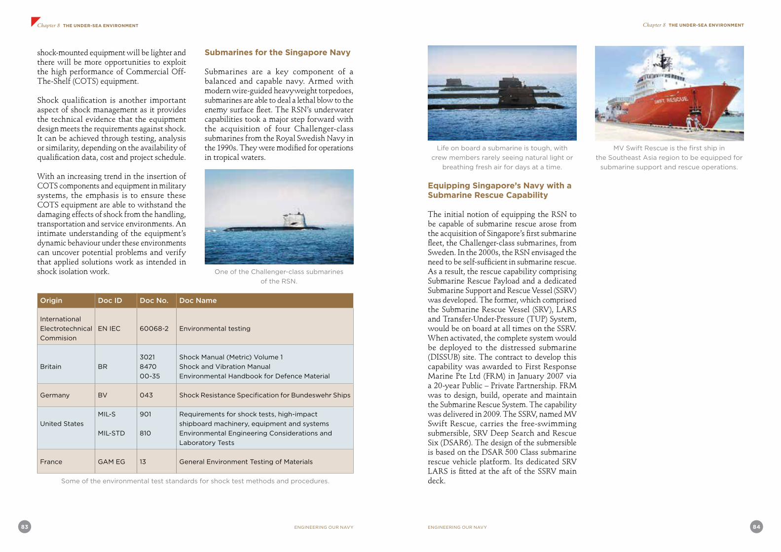
83 ENGINEERING OUR NAVY ENGINEERING OUR NAVY 84
Chapter 8 THE UNDER-SEA ENVIRONMENT Chapter 8 THE UNDER-SEA ENVIRONMENT
shock-mounted equipment will be lighter and there will be more opportunities to exploit the high performance of Commercial Off-The-Shelf (COTS) equipment.
Shock qualification is another important aspect of shock management as it provides the technical evidence that the equipment design meets the requirements against shock. It can be achieved through testing, analysis or similarity, depending on the availability of qualification data, cost and project schedule.
With an increasing trend in the insertion of COTS components and equipment in military systems, the emphasis is to ensure these COTS equipment are able to withstand the damaging effects of shock from the handling, transportation and service environments. An intimate understanding of the equipment’s dynamic behaviour under these environments can uncover potential problems and verify that applied solutions work as intended in shock isolation work.
Submarines for the Singapore Navy
Submarines are a key component of a balanced and capable navy. Armed with modern wire-guided heavyweight torpedoes, submarines are able to deal a lethal blow to the enemy surface fleet. The RSN’s underwater capabilities took a major step forward with the acquisition of four Challenger-class submarines from the Royal Swedish Navy in the 1990s. They were modified for operations in tropical waters.
One of the Challenger-class submarines
of the RSN.
Origin Doc ID Doc No. Doc Name
International
Electrotechnical
Commision
EN IEC 60068-2 Environmental testing
Britain BR
3021
8470
00-35
Shock Manual (Metric) Volume 1
Shock and Vibration Manual
Environmental Handbook for Defence Material
Germany BV 043 Shock Resistance Specification for Bundeswehr Ships
United States
MIL-S
MIL-STD
901
810
Requirements for shock tests, high-impact
shipboard machinery, equipment and systems
Environmental Engineering Considerations and
Laboratory Tests
France GAM EG 13 General Environment Testing of Materials
Some of the environmental test standards for shock test methods and procedures.
Life on board a submarine is tough, with
crew members rarely seeing natural light or
breathing fresh air for days at a time.
Equipping Singapore’s Navy with a Submarine Rescue Capability
The initial notion of equipping the RSN to be capable of submarine rescue arose from the acquisition of Singapore’s first submarine fleet, the Challenger-class submarines, from Sweden. In the 2000s, the RSN envisaged the need to be self-sufficient in submarine rescue. As a result, the rescue capability comprising Submarine Rescue Payload and a dedicated Submarine Support and Rescue Vessel (SSRV) was developed. The former, which comprised the Submarine Rescue Vessel (SRV), LARS and Transfer-Under-Pressure (TUP) System, would be on board at all times on the SSRV. When activated, the complete system would be deployed to the distressed submarine (DISSUB) site. The contract to develop this capability was awarded to First Response Marine Pte Ltd (FRM) in January 2007 via a 20-year Public – Private Partnership. FRM was to design, build, operate and maintain the Submarine Rescue System. The capability was delivered in 2009. The SSRV, named MV Swift Rescue, carries the free-swimming submersible, SRV Deep Search and Rescue Six (DSAR6). The design of the submersible is based on the DSAR 500 Class submarine rescue vehicle platform. Its dedicated SRV LARS is fitted at the aft of the SSRV main deck.
MV Swift Rescue is the first ship in
the Southeast Asia region to be equipped for
submarine support and rescue operations.

85 ENGINEERING OUR NAVY ENGINEERING OUR NAVY 86
Chapter 8 THE UNDER-SEA ENVIRONMENT Chapter 8 THE UNDER-SEA ENVIRONMENT
MV Swift Rescue and Rescue Payload
MV Swift Rescue is an 85-metre-long vessel built using the American Bureau of Shipping specifications and equipped with Dynamic Positioning-2 capability. It houses the rescue payload, certified by classification society Lloyd’s Register, on its main deck where the main bulk of the rescue mission will be executed. Centred at the aft deck, the 30t LARS is able to launch and recover the submersible up to Sea State 5 without the aid of swimmers. DSAR6, operated by two pilots and one Chamber Attendant with a capacity for 17 rescuees, is normally stowed in the sheltered hangar mid-ship on the main deck where the TUP system is installed. The submersible DSAR6 has an aft hatch to enable the pressurised transfer of personnel into the TUP system. A Deck Handling System is in place to move the submersible from its stowed position to under the LARS for deployment. Swift Rescue also houses the Remotely Operated Vehicle (ROV) system which can be deployed to survey or inspect the DISSUB site and assist to clear debris around the rescue hatch before deploying DSAR6.
The comprehensiveness of the rescue approach is evident, especially in the medical facilities that have been incorporated on board MV Swift Rescue. Besides the TUP system, medical areas for various treatments (e.g. triage, sickbay and high dependency ward) have been identified. These are all located on the same deck as the TUP system to facilitate casualty movement and accountability. In addition, the ship has a helipad that is able to land a 12t helicopter. This allows flexibility to bring more medical support from the mainland, and to transfer casualties to mainland hospitals when required.
The ship is also able to handle escape scenarios. The six-man Rigid Hull Inflatable Boat is equipped with a scoop to facilitate the recovery of personnel at sea. Upon recovery, they can either be transferred to MV Swift Rescue via its side jetty, or directly onto its main deck depending on the sea conditions.
Adherence to international standards, where possible, has been practised for the systems design evolution. For instance, all hatches and interfaces are standardised to STANAG 1297 rules. This allows interoperability with the systems and submarines of other nations that meet the same standards.
Sophisticated technology, equipment reliability and redundancy as well as system safety are critical for the success of rescue missions. MV Swift Rescue is equipped with the Integrated Navigation & Tracking System which monitors the ROV, DSAR6 and DISSUB underwater during operation.
There are some significant improvements in the RSN rescue system that are different from many existing rescue systems. For instance, the lithium polymer battery, with its high energy density, is used on DSAR6 to enhance its performance. An air-conditioning system has been incorporated as part of the tropicalisation efforts – a first in SRV design – and this was made possible with the lithium polymer battery. In addition, it has a more capable trim system as well as an integrated skirt design complete with its own dewatering capability. Furthermore, the LARS is designed to deploy DSAR6 without assistance from swimmers, unlike most systems currently in use.
Another achievement is the creation of a
removable raft on which DSAR6 and the TUP system are placed. This is a removable raft that allows the transfer of the rescue assets in a clean, single lift to the Vessel Of Opportunity thus saving precious time during the preparation phase.
System safety was a critical concern during the design phase. The DSAR6 pressure hull has undergone hydrostatic tests before its assembly. Moreover, the lithium polymer battery system used in DSAR6 is certified by a classification society, which validated its safety features such as automatic cut-off for charging, and its visual and audio warning system for low battery status. These batteries are housed in separate pressure pods from the rescue chamber of the submersible – this adds an additional protective barrier to the crew on board the submersible and allows the pilots to jettison the battery pod if it is flooded.
Overall, the complete rescue system is one of the few in the world to incorporate various aspects of the rescue mission onto a single dedicated platform.
DSAR6 being lowered into the water.
Article credit: DSTA

87 ENGINEERING OUR NAVY ENGINEERING OUR NAVY 88
Chapter 9 THE INFORMATION DOMAIN
THE INFORMATION DOMAIN
The Information Domain… Then
Keeping watch at sea on board one of the former “B Class” patrol craft of the RSN was a challenging experience for even the most experienced officers of the watch (OOWs). The OOW was stationed on the open bridge that was exposed to the elements. He had access only to the usual visual means for navigation as there was no radar display on the open bridge. The radar was situated one deck below in the operations room (or combat information centre as it is known today), and the OOW had to rely on radar fixes provided by the radar plotter on watch. Information exchange was via voice communication using the ship’s point-to-point communications system or by means of a voice pipe between the bridge and the operations room. Periodically, the OOW had to validate the radar fixes personally and this involved a quick dash down the hatch to the operations room and back again to the bridge. In a congested shipping environment this could be a somewhat stressful experience (especially if the OOW was on the way up the ladder and a watch keeper on the bridge was unwittingly standing on the hatch cover!).
Watch-keeping in the engine room involved a continual circuit of monitoring, checking and manually recording the status of the various systems in the engine room to ensure that equipment was functioning within designed operating limits. Communication with the bridge team was essential especially during operational manoeuvres as this required quick responses to changes in the tactical situation.
In the operations room or combat information centre, equipment was largely standalone systems and important tactical information was manually transposed to a tactical plot
that had to be manually updated. Positional inaccuracies, latency of information flow and problems in time synchronisation often led to rather confused and chaotic tactical situational awareness.
The Information Domain… Now
Modern technology has transformed how information is collected, transmitted, integrated, analysed and displayed on board our naval ships. Our engineers first specified and designed integrated communications systems so that important positions within the ship could be connected in a network. In addition, positions on the bridge and combat information centre could switch between internal ship communications and tactical communications with other units at sea. Starting with the patrol vessels and then the Endurance-class LST, our engineers designed and integrated the various systems on the bridge, combat information centre and the engine room tailored to the specific needs of our operations personnel.
On the bridge today are electronic charts integrated with precision positioning systems, radar and other sensor information, as well as decision support capabilities to facilitate maritime domain awareness. Electro-optic systems augment visual and radar surveillance, tracking and identification including weapon direction and control. Acoustic systems provide information about the undersea environment. The status of all important engine room equipment can be monitored and machinery control can be effected allowing effective firefighting and damage control functions from the bridge.
The engine room today is usually unmanned with automatic monitoring and control functions in a separate compartment. A system-wide display of the status of all machinery on board is available. Remote control of equipment and planning and decision support functions relating to ship
Chapter Ninestability, firefighting and damage control can be performed here.
The combat information centre is today the principal information node for combat operations, extending well beyond the visual and radar horizons. In addition to information collected by shipboard sensors, information from off board sensors and platforms can be made available, allowing the ship to be part of a collaborative distributed combat system that can influence an extended maritime area of operation. The information network today is so sophisticated that it is possible to orchestrate a coordinated attack from various platforms to saturate an enemy’s defences. This network centricity allows sophisticated emergent capabilities such as system wide resilience as well as the ability to control networked sensors and weapons from various remote platforms or locations within the network.
Key Building Blocks
The current capabilities of the RSN in the information domain have been made possible with the following system design considerations and decisions. These constitute the key building blocks.
• Precision location and time synchronisation across the entire network
• A common operational data dictionary across services and the SAF
• An indigenous common information architecture across the SAF, yet open and interoperable with allied forces
• The strategic decision to have an indigenous capability in the information domain
• Information R&D capabilities especially within DSO
• Command, control, communications, computers and intelligence (or ‘C4I’) development and integration capabilities in the DSTA and the defence industry
• The operations – technology collaboration
and trust among operational users, scientists and engineers
Modern precision location and timekeeping and synchronisation systems have overcome the early problems associated with networked enabled operations. In the days of manual tactical plots, it was next to impossible to have a good appreciation of what really happened in a post-mission debrief. Imprecise location and the congested traffic environment posed a severe challenge to achieve a recognised situation picture around a naval ship or task group. Even with automated information systems, there was the challenge of synchronising both positions and time until the global positioning system and other satellite based systems provided solutions to these challenges.
Even more important were policy decisions regarding systems architecture. A common operational data dictionary was implemented to ensure coherence and interoperability for operations across the entire SAF. Our networks had to be able to work across various frequencies in the electronic spectrum given that the RSAF, the RSN and the Singapore Army operations had their own specific requirements. In addition, while it was important to have a sophisticated, resilient and protected indigenous information architecture, the requirement for interoperability with allied forces was also a key design requirement. While RSN ships and platforms had their unique-to-SAF tactical networks, they were also equipped to interoperate with ships and platforms of other friendly navies.
Operations and technology collaboration plus trust in our engineering capabilities have been key enablers. The RSN recognised that critical operating and warfighting doctrine had to be encapsulated in its command, control, communications, computers, intelligence, surveillance and reconnaissance (C4ISR) systems, and this required close collaboration between operations and technology staff.

89 ENGINEERING OUR NAVY
Chapter 9 THE INFORMATION DOMAIN
ENGINEERING OUR NAVY 90
Chapter 9 THE INFORMATION DOMAIN
These systems had to be both customised for the RSN and regularly and swiftly updated and modified to changing threat circumstances. This required a responsive indigenous capability. Trust and collaboration allowed DTC engineers to apply their learning from various projects such as the MGB upgrade and MCV programmes to design and develop C4ISR systems indigenously first for the PVs, then the Maritime Patrol Aircraft and LST.
The close operat ions-technology collaboration culminated in the indigenous design and development of the CMS for the Formidable-class frigates – a strong testimony that the RSN was prepared to put its trust in the DTC to deliver a key capability for its new principal strike platform.
DSO Develops Key Information Systems for the RSN Frigate
DSO scientists and engineers have successfully developed the Identification (IDENT) and Threat Evaluation and Weapons Assignment (TEWA) engines for the frigate CMS. They have also played a key role in the design and development of sophisticated tactical networking systems for the RSN.
Mastery in the information domain is not confined to information networks and sense making capabilities. Using the information domain for competitive advantage requires a deep understanding of the various sensor systems that collect such information.
The high relative humidity, heavy rainfall and the atmospheric conditions in the tropics affect the performance of visual and electro-optic sensors differently from that of other operating areas. The first generation night vision devices did not work well in our operating environment. Patrolling ships had to proceed as close as half a cable1 from a darkened object before any useful identification could be made. Photographs
taken during operational patrols and sorties often required digital image enhancement by our scientists and engineers before useful information could be obtained. These were the early days that required the development of image processing capabilities in DSO. The RSN was an early user of imaging equipment using the 3 to 5 micrometer wavelengths as the 8 to 12 micrometer systems did not prove adequate. The requirement of a passive infrared search and track system for the RSN was also difficult to fulfil because of environmental conditions.
Sophisticated image processing for both radar and electro-optical systems capabilities were borne out of the requirement to get every bit of useful information for tactical advantage. The synthetic aperture radar was one area that had promise. High frequency radars and multi-static radar technologies were also explored for information advantage.
1 A cable is a unit of measurement in maritime use around the world, equivalent to one-tenth of a nautical mile, or 185.2m.
“ I recall presenting our R&D work on Artificial Intelligence technique to COL Wellman Wan from the Navy, the operations manager for the Frigate programme. DSO's work had not been shown to work on actual platforms, only in simulation. But COL Wan put his trust in the DSO group when he engaged the group for the development of the IDENT and TEWA engines for the Frigate Programme. I am glad we did not disappoint the Navy. ”Dr How Khee Yin, Director, Information
Systems Division, DSO
“ I remember the team putting in many hours, days and weeks vigorously testing the engine in a testbed centre in DSTA. When the engine finally passed the test, I was thinking we could finally see it operate on board the frigate. Never did I think we had to put in even more hours and days testing it during sea trials and battling sea sickness, so much so that COL Wan commented that I looked like part of their ship crew. When we finally saw the engine perform in the first live-firing, the feeling was exhilarating. It was that moment that I felt so proud and honoured to be part of the team (RSN, DSTA, DSO and ST) that had contributed and played a part in the defence of Singapore. ”
Valerie Leong Sok Kuen, Software Engineer,
TEWA Engine, DSO
“ When I think back of the Frigate programme, five 'C's come to my mind. These are not the usual five 'C's most people are thinking of. For me, the five 'C's are (1) Close Communications (2) 'Can Do' Attitude (3) Commitment (4) 'Sea' Sickness and (5) Contentment. We had a lot of 'Close Communications' with the various 'C'olonels, Squadron 'C'hiefs and our DSO/DSTA/ST 'C'olleagues throughout this programme, to bounce off ideas and experiences that had helped us to better understand the programme and build closer ties along the way. Our 'Can Do' Attitude drove us towards a common goal. We encountered challenges along the way but it was our 'Commitment' and determination to build a successful IDENT Engine that kept us going. When I got to set sail to test the system, I encountered the next 'C'; or should I say, 'Sea' Sickness. I really need to salute our sailors who can tolerate those high sea states which threw me totally off course. Yes, it was tough. However, when I finally found the IDENT Engine useful and relevant to the RSN, I could not help but have a total sense of 'Contentment'. ”Dr Foo Shou King, Project Leader,
IDENT Engine, DSO

91 ENGINEERING OUR NAVY ENGINEERING OUR NAVY 92
Chapter 9 THE INFORMATION DOMAIN Chapter 9 THE INFORMATION DOMAIN
Fusion Engines for Command and Control
DSO has developed two key data fusion engines, namely the IDENT and TEWA engines.
In order to determine the identity (friendly, neutral or hostile) and platform type (e.g., fighter or helicopter) of a target, the IDENT engine takes in inputs from multiple sources and updates the data on incoming evidence. At the same time, the TEWA engine continuously evaluates which targets pose a threat to friendly forces and then assigns the best weapon at the best time to engage them.
The IDENT and TEWA engines have been implemented in the RSN Frigate CMS. To explain the science and technology behind the IDENT and TEWA engines, the Frigate CMS application will be used as an example.
Frigate CMS
DSO was tasked to design, develop and deploy the IDENT and TEWA fusion engines in the CMS on board the RSN’s stealth frigates.
These frigates are highly capable warships. They are equipped with advanced state-of-the-art combat capabilities, allowing them to perform a wide spectrum of missions and also deal with various threats in all the three dimensions of naval warfare – surface, air and underwater.
The CMS is an advanced computer program that is able to detect, track, identify and prioritise contacts, and assign weapons to engage enemy targets which are facing the ships. The many sensors and weapons aboard the frigates are integrated into this
one command and control system, which simplifies the decision-making process to fire the ship’s missiles and other weapons. As such, less time is taken and a smaller crew is required to man the combat systems.
If the CMS is likened to the brains aboard the warships, then the IDENT and TEWA engines that DSO has developed are the intelligence that enables the frigate to do more and respond in a much shorter time.
IDENT Engine
The IDENT engine attempts to evaluate the identities and platforms of all air and surface targets detected by the ship’s sensors such as radars and datalinks. On top of that, it also watches out for any suspicious behaviour, such as a neutral aircraft behaving like a hostile one.
To illustrate how the IDENT engine identifies the unknown air tracks around the air space, two sample sets of data within a knowledge base are used as evidence: commercial flight routes and IFF codes. To generate an overall confidence value of an air track’s identification, we use the certainty factor (CF). CF measures the degree of belief. The degree of belief to a hypothesis is computed via the supported evidence. Using the CF, the belief of the unknown air track’s identification with the evidences of the commercial flight routes and IFF codes, are computed. The higher the belief, the more confidence that the unknown air track’s identification is a commercial aircraft.
TEWA Engine
While the IDENT engine continues to establish the identities of air tracks, the TEWA engine evaluates those that are threatening the frigates as well as
the friendly ships she is protecting, and recommends the best weapon to engage them.
The TEWA engine quickly assesses all air tracks to sift out those that pose a threat to the frigates. These detected threats are then evaluated to determine their threat levels based on their kinematics, while taking into consideration other factors such as the presence, priorities and capabilities of our own forces.
With a prioritised list of threats, the TEWA engine uses weapon models and
real-time weapon status information to compute the effectiveness of its available suite of weapons against them. Using the information computed for every threatening air track, the TEWA engine then recommends a prioritised list of target engagements to optimise the use of weapons, while maximising the chances of survival of our own forces.
The results from the TEWA engine, such as the threat levels, are used to recommend target engagements. Associated details are then presented in a format that is intuitive to the ship’s crew.
Multiple sources inputHandle ambiguous and conflicting evidences
Real time dynamic updating across time
Air and surface targets
Target Classification Identifying the platform types
Conflict and Belief Combination
Extensible software architecture
Surface Domain Alerts
Surface Domain Evidences
Air Domain Alerts
Air Domain Evidences
Stable automatic threat evaluation
Optimised weapon assignment
Assets
High Threat
Automatic kill assessment
Medium Threat
The TEWA engine gives our fighting forces a decisive edge.
Target classification depends on several different input sources and algorithms.
93 ENGINEERING OUR NAVY ENGINEERING OUR NAVY 94
Chapter 9 THE INFORMATION DOMAIN EPILOGUE
Tactical Networking for the RSN
Technological advances in wireless networking play a critical role in driving this transformation. DSO’s research and development in the field of tactical Mobile Ad hoc Networking (MANET) spans the design, development and validation of its suite of tactical MANET protocols for the RSN.
The design of the suite of tactical MANET protocols adopts a layered architecture approach. By adopting this modular approach, a complex networking problem is broken down into more manageable modules, allowing each layer to be independently designed, developed and upgraded. Similar to the Transmission Control Protocol/Internet Protocol (TCP/IP) model, this suite of tactical MANET protocols comprises four layers: the link, network, transport and application layers.
Media Access Control (MAC) is a key function of the link layer that allows multiple nodes to share a common wireless transmission medium. The Time-Division Multiple Access (TDMA) protocol is a natural choice for tactical networking as it is robust in the dynamic MANET environment. However, it suffers from poor bandwidth utilisation when the network loading gets uneven due to its static bandwidth allocation. Bandwidth is wasted whenever a node is unable to fully utilise the allocated bandwidth in its assigned time-slot, even though there are other loaded nodes in the network. Furthermore, in the event of a light network load, a node still needs to wait for its assigned time-slot before it can transmit data, resulting in significant network access latencies. All these undesirable characteristics of the
conventional TDMA protocol provided motivation to look for a better solution.
To better utilise the scarce radio bandwidth resources, DSO designed a MAC protocol that allows a node that is unable to fully utilise the allocated bandwidth in its assigned time-slot to dynamically re-allocate the unused time to a loaded neighbour. In the event that the recipient of such priority given is unable to fully utilise the extra time given in the same time-slot, it can release it to another loaded neighbour. The scheme adapts well to varying levels of traffic at each node and achieves better utilisation of the bandwidth than a conventional TDMA scheme.
Routing is a key function of the network layer that allows data packets to be exchanged seamlessly between any two nodes in a multi-hop network. For tactical networking, proactive routing protocols are preferred over their reactive counterparts due to their lower path set-up latencies. Proactive routing protocols can be further classified into link-state (LS) and distance-vector (DV) routing protocols. LS routing enjoys fast route convergence but suffers from high routing overheads as LS updates are regularly flooded throughout the network. Conversely, the routing overheads for DV routing are significantly lower but route convergence is slower as nodes only exchange distance vectors with their immediate neighbours. Hence, both the conventional LS and DV routing protocols are unsuitable for tactical networking using narrowband radios.
Article credit: DSO
EPILOGUE
What insights can one obtain from this narrative of Engineering Our Navy? It appears that it is not just an issue of having more engineers and scientists. It is a whole organisational mindset and approach as well as a shared belief and vision among all the various stakeholders. This is also a narrative of the consistent and pervasive application of systems thinking and systems engineering approaches.
The opening address of Mr Peter Ho (then Permanent Secretary Defence) at the Naval Platform Technology Seminar 2003 illustrates the strategic thinking underpinning this approach – the commitment to invest in an ‘irreducible minimum’ in building capabilities in critical and strategic technologies, the continual drive for transformation amid continual change and fostering an environment where experience is tapped and knowledge is shared vertically and horizontally throughout the organisation.
“On the evening of 21st October 1967, two Egyptian missile boats off Port Said fired four Russian-made Styx anti-ship missiles and sank the Israeli Navy destroyer, Eilat. While this was a sideshow in the Six Day War, the sinking of the Eilat was a seismic event in naval warfare.
For the first time, a naval battle was decided not by guns or torpedoes or bombs, but by a new weapon — the anti-ship missile.
The Israeli Navy learnt its lesson from the sinking of the Eilat. Six years later, in the 1973 Yom Kippur War, its ships were armed with the new Gabriel surface-to-surface missile system. More than that, the Israeli Navy ships were equipped with electronic warfare systems to defeat the Styx missile. In the first surface-to-surface missile battle in the history of naval warfare, the Israeli Navy ships, protected by their EW systems, successfully penetrated a curtain of Styx missiles fired by the Syrian Navy. They then launched their Gabriel missiles and sank five Syrian ships.
These naval battles have helped to shape modern naval warfare. The anti-ship missile has not only transformed naval tactics, but also profoundly influenced
the design of ships and their fighting systems.
After 1967, the anti-ship missile became part of the essential inventory of the modern warship, supplanting the gun as the main offensive weapon.
In turn, the anti-ship missile threat compelled navies to develop a host of missile warning systems and electronic countermeasures to protect their ships. Indeed, the lack of up-to-date countermeasures can be fatal. On 4th May 1982, two low-flying Argentinean Super Etendards caught the Royal Navy destroyer, HMS Sheffield, unawares. One of the two AM39 Exocet missiles fired by these aircraft locked onto the Sheffield and hit it square amidships. The damage was too great and a few days later, the Sheffield sank. Twenty men lost their lives.
As the designs of anti-ship missiles improve, soft-kill anti-missile electronic countermeasures may not be enough. After the Yom Kippur War, the Israeli Navy began preparing for the next war by developing the Barak anti-missile missile system.
It is never-ending. The combat effectiveness

95 ENGINEERING OUR NAVY ENGINEERING OUR NAVY 96
EPILOGUE EPILOGUE
of a new design or fresh upgrade of an anti-ship missile is short-lived, as ever more sophisticated electronic countermeasures and anti-missile systems emerge. This imbalance is then redressed in the development of the next generation of anti-ship missiles.
So today, the latest anti-ship missiles have electronic counter-countermeasures incorporated into their seekers in order to defeat the target ship’s electronic countermeasures and to defeat hard-kill anti-missile systems, and the flight route can be timed so that two or more missiles arrive simultaneously at one target, saturating and defeating the ship’s defences.
If an anti-ship missile can reach supersonic speeds, reaction times would be sharply reduced, and current anti-missile systems would be rendered impotent and this would allow the supersonic missile to penetrate the ship’s defences. This is not a theoretical construct. The technology is available. France and Germany teamed up to develop the ram-jet ANF supersonic anti-ship missile. While this project fell through, there are already a couple of such missiles under development. The most prominent one is the Brahmos, which is a joint project between India and Russia. The Brahmos will be deployed on Indian Navy ships. Russia is also adapting its Kh-31P anti-radar missile to produce an air-launched supersonic anti-ship missile code-named Krypton. Maybe MBDA will be prompted to revive the ANF supersonic missile programme.
Advances in technology mean that there is constant churn in modern naval warfare. If we fail to stay ahead of the curve, then we will be condemned to repeating the mistakes of the last war, relearning the
painful lessons of the Eilat and the Sheffield. Because the stakes are high, armed forces have no choice but to invest time and resources in developing innovative new concepts and adopting new technologies in order to be ready for the next war.
I will explain this point by giving examples from the experience of the SAF.
The development of the SAF has been, and will always be, constrained by limited resources of budget and manpower. While larger armed forces can develop their capabilities by growing and spending more, the only feasible approach for the SAF to maintain its strategic edge lies in doing things smarter and in stretching the value of every defence dollar.
Among other things, this means keeping abreast, and sometimes running a bit ahead, of evolving trends in modern warfare and technology. This also means acquiring capabilities in critical technologies, so that we can either be a smart buyer of state-of- the-art weapons systems, or develop specialised systems to meet our unique operational needs.
In certain strategic areas, like naval fighting platforms, we buy advanced systems in order to obtain an early advantage and this advantage is not just obtained by the hardware acquired, but also by the experience gained in operating these systems, as this enables us to rapidly move up the learning curve.
The RSN’s acquisition of the Lurssen-Werft 45-metre MGBs in the 1970s is a good illustration of this approach. Armed with the Gabriel anti-ship missiles that the Israeli Navy used to good effect in the Yom Kippur War of 1973, the MGBs were
very advanced for their time. However, with rapid advances in naval technology, obsolescence soon crept in. But by then, we had gained a lot of experience operating this first generation of missile ships and that experience gave us the confidence to define a second generation of missile-armed ships that became our MCVs of today.
Whenever necessary, we improve and upgrade the equipment to enhance their performance to meet new operational requirements. So rather than dispose of the MGBs when they approached obsolescence, we upgraded them. We installed a suite of electronic warfare systems to provide "soft-kill" protection against anti-ship missile attacks, and we added longer-range Harpoon missiles to the existing battery of Gabriel missiles and the combination of the Harpoon and Gabriel missiles improved the MGBs’ attack and penetration capability.
Meanwhile, more capable electronic countermeasures and the Barak anti-missile missile system were acquired for the MCVs, giving the RSN’s main strike force a stronger defensive shield against anti-ship missiles.
From 2007 onwards, the Navy’s stealth frigates will enter service. These third generation platforms will be equipped with a robust hard-kill anti-missile capability in the form of the new Aster missile system that has been designed to deal with future generation of anti-ship missile threats.
Our frigates will initially be equipped with the Harpoon anti-ship missile system. But going forward, like the first generation Gabriel-armed MGBs, these third-generation platforms must eventually be upgraded and armed with a new generation of anti-ship missiles that can
defeat the most advanced defences. Like other navies, the RSN will have to look ahead to future anti-ship missile systems and one promising option is the supersonic anti-ship missile that I mentioned earlier. But it will need an additional capability to discriminate legitimate targets against the cluttered background of one of the busiest shipping lanes in the world.
In Singapore, while we buy whatever and whenever we can, off-the-shelf, there will always be an "irreducible" minimum of investment in strategically critical technologies that Singapore needs to commit to in order to stay ahead. That "irreducible" minimum sometimes requires MINDEF to invest in R&D technologies and systems that we know could become irrelevant, redundant, or even obsolete in the future, either because they become available on the open market, or because new operating concepts make them unnecessary. But it is a price that we have to pay in order to develop and sustain our defence technology capability.
There are some critical technologies that will feature in the development of the third generation Navy. These include stealth, electronic warfare, guided weapons, and unmanned systems. Because of their importance, an "irreducible" minimum of R&D must be invested in these critical technologies.
Stealth protects by reducing the signature of platforms and thus the likelihood of detection. It confers the ability to surprise in operations because the stealthy platform is detected much later than an unstealthy one. The ships of the third generation Navy must be stealthy. So we consider stealth a critical technology that we must develop capabilities in and our collaboration with France in development

97 ENGINEERING OUR NAVY ENGINEERING OUR NAVY 98
EPILOGUE EPILOGUE
of our new stealth frigates is a vital step in this direction.
The ability to dominate the electromagnetic spectrum through electronic warfare provides a critical operational advantage that is both highly prized and jealously guarded. While EW systems can easily be bought from the open market, they are mostly just black boxes. The advantage goes to the armed forces that can tailor specialised techniques and develop customised systems more advanced than those available off-the-shelf and this is why electronic warfare has been one of the most important and long-standing R&D programmes of DSO, and perhaps its most secretive.
The dominance of the anti-ship missile in modern naval warfare reflects a wider military trend of the increasing importance of stand-off precision weapons. This trend clearly emerged in Operation Desert Storm, gathered momentum in Kosovo and during Operation Enduring Freedom. But the use of precision guided weapons reached a peak in Operation Iraqi Freedom in which almost 70% of all ordnance were precision weapons, compared to just 8% in the first Gulf War.
For an armed forces like the SAF, with limited resources and manpower, the force multiplication effects of guided weapons constitute an important strategic advantage. This was something we recognised early on with the acquisition of the Gabriel missile system for our MGBs. But to better understand guided weapons, it was not enough just to buy such systems off-the-shelf, as we did with the Gabriel missile system. So in the early 1980s, DSO embarked on the development of a TV-guided bomb as a learning project for its young engineers and scientists
just out of university. It was not rocket science. But while the outcome was only an engineering field prototype, it gave our engineers and scientists in DSO an excellent learning opportunity in design, testing and evaluation and this was the foundation upon which they built up expertise in technologies such as aerodynamics, flight control, navigation and guidance and such technologies overlap into another strategic area for the SAF, namely, unmanned systems.
As a result, the SAF today has access to expert advice for the evaluation not just of guided weapons, but also of unmanned vehicles which share with precision weapons the need for good guidance, navigation and control systems.
Going forward, the demand for guided weapons and for unmanned systems can only increase. Indeed, the use of UAVs for surveillance and strike has already begun to change the rules of warfare, especially since Kosovo. Just a year ago, a Predator UAV in Yemen launched a missile accurate enough to hit terrorists in a car.
By enabling an armed forces to act on intelligence rapidly, in minutes instead of hours or even days, UAVs are likely to prove to be a significant force multiplier in the long run and it is an area where the SAF must gain an early advantage. In addition, UAVs have the potential of overcoming the problem, perhaps unique in Singapore, of the limited number of pilots we can generate due to our small population base and we have already gained substantial experience through years of operating the short range Pioneer RPV, and the medium range Searcher UAV. To understand the technologies of unmanned systems more deeply, we even made an "irreducible minimum"
investment in the development of a target drone, not unlike the ubiquitous Chukar. Again, the outcome was a field prototype. But the real gain was in expertise build-up. That expertise was leveraged in a recently concluded long-term study for a High Altitude Long Endurance (HALE) UAV with an integrated airborne surveillance and communications system and such a HALE UAV would provide continuous temporal coverage over a very large area, and could potentially replace our E2Cs in the long term.
In describing our experiences with guided weapons and UAVs, I am making a couple of points. Let me summarise.
My first point is that there has to be a willingness to commit investments in building up capabilities in critical and strategic technologies. While these investments may not result in any weapon or system that can be deployed, this "irreducible minimum" is necessary to stay ahead not just of the technology curve, but also of the strategic curve.
My second point is that there is no end to change and transformation. This means that we must always be thinking about how to fight the next war, not the last, and preparing and equipping ourselves accordingly.
My third and last point is that the exploitation of technology for strategic advantage is best achieved in an environment where experience is tapped, and knowledge is shared vertically and horizontally throughout the organisation. To do the long-term study of the HALE UAV in Singapore depended on mining the accumulation of operational experience and technical expertise throughout the defence establishments in Singapore.
In conclusion, a long-term view is necessary to meet the multi-faceted challenges facing today’s modern navies. Investments in time and resources have to be made now to seek innovative responses, in order to be ready to respond effectively to future challenges and changes that may come our way.
And on that note, I wish you all a fruitful and enjoyable seminar.”

99 ENGINEERING OUR NAVY ENGINEERING OUR NAVY 100
ACKNOWLEDGEMENTS ACKNOWLEDGEMENTS
Lands and Estates Organisation in 1991, and assumed the position of Director (Building and Infrastructure) and Director (Procurement) after the formation of DSTA.
In over three decades of service in MINDEF, RADM (Ret) Richard Lim has had roles in all phases of the systems development life cycle of large scale defence
systems. He has held the positions of Deputy Secretary (Technology), Chief Executive DSTA, Chief of Navy, and Director Joint Operations and Planning. He continues his professional interest in systems engineering, and serves in advisory and board positions in both the private and public sectors. He is Chairman of ST Logistics, a board member of ST Marine and the National University Health System, and Deputy Chairman of Land Transport Authority. He is also Chairman of the governing board of St. John’s Island Marine Laboratory and Chairman of the National Maritime Safety at Sea Council.
Mr Yeo Kee Kong obtained his BEng and MEng in Electrical Engineering from NUS in 1982 and 1985, respectively. He joined DSO as an R&D engineer in
1982 and was posted to DMO from 1987 to 1994. While in DMO, he oversaw the build-up of EW system capability for the RSN and RSAF. He contributed to major RSN platform programmes including leading the Patrol Vessel programme. When he returned to DSO in 1994, he led the Radar Research Division. Since DSO’s corporatisation in 1997, he has held several appointments including Director (Advanced Development) focussing on delivering systems to the SAF, and Director for Information Division and Network Division. He is currently the Director of Quality Division.
RADM (Ret) James Leo graduated with an honours degree in Mechanical Engineering from the then University of Malaya in 1969. Upon graduation, he
was enlisted first as a logistician and then as a general line officer. He was Head Naval Logistics from 1978 to 1980, Commander from 1985 to 1990, and Chief of Navy from 1990 to 1991 before he retired from the Navy. James was seconded to the Port of Singapore Authority as its CEO before retiring in 1995. James is also a Chartered Engineer, a Fellow of the Institution of Engineers (Singapore) and a Member of the Institution of Mechanical Engineers (UK).
Dr Koh Wee Jin obtained his BSc from the University of Manchester, Institute of Science and Technology, UK in 1979, MSc from NPS, USA in 1987
and PhD from Ohio State University, USA in 1995. He has worked in DSO since 1981, specialising in EMI/EMC. He has held various appointments including Head of Research in Electromagnetics, Head of Electromagnetic System Lab and Head of Centre of Excellence in Electromagnetics. In 2007, he was appointed Distinguished Member of Technical Staff in DSO. He is an adjunct associate professor in the School of Electrical and Electronic Engineering in NTU, and the co-director for Electromagnetic Effects Research Laboratory.
Mr Quek Pin Hou graduated from the University of Western Australia in Electrical Engineering in 1969 under a Colombo Plan Scholarship. He
joined MINDEF in September 1970 to work on the Missile Gun Boat project and was the Project Director for the RSN Missile Corvette Project from 1983 to 1991. Pin Hou was one of the principal members of the founding team for DSO in 1977, before joining the SPO as Deputy Director, and later as Deputy Director of DMO. He became Director of
ENGINEERING OUR NAVY would not have been possible without the hard work, support and encouragement of many people. General thanks are also due to the teams at DSO National Laboratories, Naval Operations Department, Navy Information Centre, MINDEF Communications Organisation, Defence Science and Technology Agency, Defence Industry and Systems Office and many others – too numerous to name – who have assisted us in one way or another, in the production of this book.
Authors
Mr Goh Yong Han graduated from NUS in 1997 with a BEng in Electrical Engineering (1st Class Honours), and obtained his MEng in Electrical Engineering
from NUS in 1998 under the NUS Research Scholarship, as well as MSc in Electrical and Computer Engineering from the University of California, San Diego, in 2007, under the DSTA Postgraduate Scholarship. He is currently a Senior Principal Engineer with DSTA’s Naval Systems Programme Centre, focusing on underwater and unmanned systems. He has worked on the Challenger-class submarine upgrade, undertaken defence research and development at DSO, managed research and technology projects at MINDEF, and led the Mine Countermeasure Vessel upgrade programme.
Mr Ho Jin Yong graduated from the University of Newcastle, Australia, in 1972 with a degree in Electrical Engineering. He joined the then Maritime
Command as a civilian engineer responsible for the maintenance of weapon systems before moving on to serve in SPO and DMO. He retired from DSO in 2005.
ACKNOWLEDGEMENTS
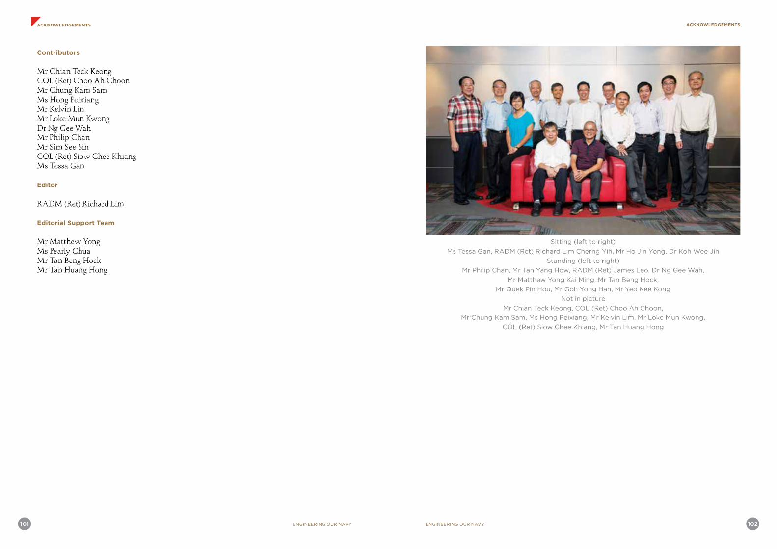
101 ENGINEERING OUR NAVY ENGINEERING OUR NAVY 102
ACKNOWLEDGEMENTS ACKNOWLEDGEMENTS
Contributors
Mr Chian Teck KeongCOL (Ret) Choo Ah ChoonMr Chung Kam SamMs Hong PeixiangMr Kelvin LinMr Loke Mun KwongDr Ng Gee WahMr Philip ChanMr Sim See SinCOL (Ret) Siow Chee KhiangMs Tessa Gan
Editor
RADM (Ret) Richard Lim
Editorial Support Team
Mr Matthew YongMs Pearly ChuaMr Tan Beng HockMr Tan Huang Hong
Sitting (left to right)
Ms Tessa Gan, RADM (Ret) Richard Lim Cherng Yih, Mr Ho Jin Yong, Dr Koh Wee Jin
Standing (left to right)
Mr Philip Chan, Mr Tan Yang How, RADM (Ret) James Leo, Dr Ng Gee Wah,
Mr Matthew Yong Kai Ming, Mr Tan Beng Hock,
Mr Quek Pin Hou, Mr Goh Yong Han, Mr Yeo Kee Kong
Not in picture
Mr Chian Teck Keong, COL (Ret) Choo Ah Choon,
Mr Chung Kam Sam, Ms Hong Peixiang, Mr Kelvin Lim, Mr Loke Mun Kwong,
COL (Ret) Siow Chee Khiang, Mr Tan Huang Hong

103 ENGINEERING OUR NAVY
ACKNOWLEDGEMENT
ENGINEERING OUR NAVY 104
GLOSSARY
Acronym Description
ACTD Advanced Concept Technology DemonstrationAIS Action Information SystemASEAN Association of Southeast Asian NationsASIST Aircraft Ship Integrated Secure and TraverseASW Anti-submarine warfareC2 Command and controlC3 Command, control, and communicatiosC4 Command, control, communications and computersC4I Command, control, communications, computers and informationC4ISR Command, control, communications, computers, intelligence, surveillance and reconnaissanceCF Certainty FactorCIC Combat Information CentreCMS Combat Management SystemCO Commanding OfficerCOL ColonelCOTS Commercial off-the-shelfDGPS Differential Global Positioning SystemDMO Defence Materials OrganisationDSC Digital scan converterDSO Defence Science OrganisationDSTA Defence Science and Technology AgencyDTC Defence Technology CommunityDTP Defence Technology PrizeDV Distance VectorECDIS Electronic Chart Display and Information SystemECM Electronic countermeasuresEGT Exhaust Gas TemperatureEM ElectromagneticEMC Electromagnetic compatibilityEMCAB Electromagnetic Control Advisory BoardEMDS Expendable Mine Disposal SystemEMI Electromagnetic interferenceESM Electronic support measuresETC Electronics Test CentreETO Electronics Technical OfficerEW Electronic warfareFMS Foreign Military SalesFOV Field of viewGPS Global Positioning SystemHADR Humanitarian assistance and disaster reliefHSA Hollandse SignaalapparatenIAI Israeli Aerospace IndustriesICIT Installation, check-out, integration, and testingICU Instrumentation Control Unit
Photo/Chart/Diagram Credit:
1. InfoComm Development Authority of Singapore (IDA): page 762. Defence Science and Technology Agency (DSTA): Cover picture, Preface, page 19 (right),
28, 32 (top and middle right), 33, 37 (middle), 38, 50 (middle and bottom right), 53 (top), 65 (top), 82 (left and right)
3. DSO National Laboratories: page 66 (top), 71, 72, 92 (top and middle)4. Republic of Singapore Navy (RSN): page 4-9, 19 (left), 21, 27, 31, 32 (top left), 36, 37
(bottom), 39-44, 46 (left), 46 (right), 47 (top), 47 (bottom), 50 (top), 51-53 (middle), 54 (top, middle and bottom), 64 (left and right), 66 (top right), 75 (top), 79, 80, 83, 84 (left and right), 86
GLOSSARY

105 ENGINEERING OUR NAVY ENGINEERING OUR NAVY 106
GLOSSARY GLOSSARY
IDENT IdentificationIFC Information Fusion CentreIFF Identification Friend or FoeILO International Liaison OfficerIP Internet ProtocolISR Intelligence, surveillance and reconnaissanceLARS Launch and recovery systemLEP Life Extension ProgrammeLG Lieutenant GeneralLMV Littoral Mission VesselLOS Line-of-sightLS Link-stateLST Landing ship tankMAC Media Access ControlMAJ MajorMANET Mobile Ad-hoc NetworkingMARSEC Maritime SecurityMC Maritime CommandMCM Mine countermeasuresMCMV Mine Countermeasure VesselMCV Missile corvetteMDS Mine Disposal VehicleMGB Missile gunboatMHS Minehunting sonarMINDEF Ministry of DefenseMOEC Multinational Operations and Exercise Control NIC Navy Information CentreNLD Naval Logistics DepartmentNOD Naval Operations DepartmentNPS Naval Postgraduate SchoolO&S Operations and SupportOEM Original Equipment ManufacturerOJT On-the-job trainingORBAT Order of BattleOT&E Operational Training and EvaluationPC Patrol craftPCA Pre-condition assessmentsPCG Police Coast GuardPMT Project Management TeamPPI Plan position indicatorPV Patrol vesselR&D Research and DevelopmentRadar Radio detection and rangingRADM Rear AdmiralRCS Radar cross sectionREDCON Readiness conditionRF RadiofrequencyRHIB Rigid hull inflatable boat
ROV Remotely Operated VehicleRSAF Republic of Singapore Air ForceRSN Republic of Singapore NavyRSS Republic of Singapore shipRTN Royal Thai NavyRTS Radio and Television SingaporeSACU Standalone communication unitSAF Singapore Armed ForcesSAL Search and locateSCSC Singapore Command and Staff CollegeSEEL Singapore Electronics Engineering LimitedSI Systems integratorSIMT System Integration Management TeamSLOC Sea lanes of communicationSMCC Singapore Maritime Crisis CentreSMS Short message sendingSMSP Submarine Maintenance and Safety ProgrammeSonar Sound navigation and rangingSoS System-of-systemsSSE Singapore Shipbuilding and EngineeringSSM Surface-to-surface missileSSRV Submarine Support and Rescue VesselTACOMINT Tactical communications intelligenceTCP Transmission Control ProtocolTDMA Time-Division Multiple AccessTEWA Threat Evaluation and Weapon AssessmentTSAS Towed synthetic aperture sonarTUP Transfer-Under-PressureUAV Unmanned Aerial VehicleUNDEX Underwater explosionUSG United States governmentUSV Unmanned surface vesselWEO Weapons Electronics OfficerWOSE Warrant Officers, Specialists, and Enlisted

107 ENGINEERING OUR NAVY ENGINEERING OUR NAVY 108
INDEX INDEX
AA4 Skyhawk 57Action Information System (AIS) 33-35Advanced Concept Technology Demonstration (ACTD) 51Air Independent Propulsion (AIP) system 64, 65Aircraft Ship Integrated Secure and Traverse (ASIST) system 46, 48Alan Bragassam 23AMX-13 light tank 57Ang Boon Hwee 81Anti-air missile, Aster 96Anti-air missile, Barak 19, 20, 71, 74, 94, 96Anti-air missile, Mistral 8, 17, 20, 44-46Anti-ship missile, ANF 95Anti-ship missile, Brahmos 95Anti-ship missile, Exocet 6, 94Anti-ship missile, Gabriel 4, 6, 10-12, 14-18, 23, 67, 94-97Anti-ship missile, Harpoon 17-20, 24, 25, 27, 29, 96Anti-ship missile, Krypton 95Anti-ship missile, Styx 94Arab-Israeli War 4Association of Southeast Asian Nations (ASEAN) 39Audrey Lam Su Ying 54
C CH-47 Chinook 45Chan Chee Hon 13Chartered Industries of Singapore (CIS) 45, 46Cheah Yew Jin 57Cheong Quee Wah 10, 13Chew Bak Koon 10Choo Ah Choon 34Combat Information Centre 4, 28, 33, 34, 87Combat Management System 28, 31, 89, 91Cossor Electronics 15
D Deep Search and Rescue Six (DSAR6) 84, 85Defence Materials Organisation (DMO) 24-27Defence Materiel Organisation 3Defence Science and Technology Agency (DSTA) 49, 50, 52-54, 57, 65, 74, 81, 82, 88, 90 Defence Science Organisation 3, 7Defence Technology Community (DTC) 51, 52, 81, 89Defence Technology Prize (DTP) 3, 33, 80Dick King 13Digital scan converter (DSC) 34Don White 29DSO National Laboratories 3, 7, 29, 30, 52, 54, 66-74, 80, 81, 88-91, 93, 97
E E2-C Hawkeye 19, 98Ed Clifford 10Elbit 45Electromagnetic compatibility (EMC) 29, 61, 70Electromagnetic Control Advisory Board (EMCAB) 30Electromagnetic interference (EMI) 7, 22, 29, 32, 70Electronic Chart Display and Information System (ECDIS) 48Electronic countermeasures 6, 7, 20, 29, 68, 94-96Electronics Test Centre 66Elta Electronics Industries 45EMC Test Centre 29Engineering Resource Lab 53Ericsson 27Exercise Bersama Padu 17Exercise Carat 17Exercise Eagle 17Exercise Flying Fish 17Exercise Malapura 17Exercise Pelican 17Exercise Singaroo 17Exercise Singsiam 17Exercise Starfish 17
F Falklands war 7, 29, 79Foo Shou King 90Frederick Chew Chih Chiang 53Frigate, Aquitaine-class 49Frigate, Formidable-class 3, 17, 49, 50, 71, 89-92, 96
G Goh Keng Swee 9, 16, 66Goh Yong Han 54
H High precision digital calculator (HP35) 14, 15HMS Sheffield 94Ho Jin Yong 4, 23Hollandse Signaalapparaten (HSA) 10-12Honeywell International 30Horsburgh Lighthouse 44How Khee Yin 90Howe Yoon Chong 18, 43
I Identification Friend or Foe (IFF) 12, 13, 15, 91Immigration and Checkpoints Authority 52Indian Ocean 39, 45Information Fusion Centre (IFC) 38, 39Installation, check-out, integration and testing (ICIT) 13-16, 24, 27Institute of High Performance Computing (IHPC) 3, 81Instrumentation Control Unit (ICU) 15Israel Aerospace Industries (IAI) 11, 12Israel Aircraft Industries 11Israeli Navy 11, 94, 95
J James Aeria 10James Leo 4, 5, 22Jeremy Han 81JYM Pillay 9, 10
K KaMeWa 45Koh Wee Jin 29
K-STER Expendable Mine Disposal System (EMDS) 52, 54, 56
L Laju incident 16Lam Khin Yong 80Landing ship tank, County-class 47, 57Landing ship tank, Endurance-class (LST) 3, 45, 46, 47, 49, 51, 52, 74, 87, 89Lee Boon Yang 80Leopard 2 tank 58Lim Ming Seong 13Lim Siong Guan 9, 80Littons 10-15Lui Pao Chuen 10Lui Tuck Yew 17
M Malacca Strait 39, 75Maritime and Port Authority of Singapore 52Maritime Command (MC) 1, 14Maritime Information Sharing Exercise (MARISX) 39McDonnell Douglas 24, 25Meulaboh, Aceh 48Mine countermeasure vessel, Bedok-class (MCMV) 54-56, 79, 80Mine Disposal System (MDS) 56Ministry of Defence (MINDEF) 1Missile corvette, Victory-class (MCV) 6, 18-28, 30-34, 44, 69, 70, 71, 74, 89, 96Missile gunboat, Sea Wolf-class (MGB) 1, 4, 6-11, 13-17, 21, 23-25, 27, 29, 30, 33-35, 44, 49, 67-69, 89, 95-97Multinational Operations and Exercises Centre (MOEC) 38MV Swift Rescue 84, 85MV Zafirah 39
N National University of Singapore (NUS) 80, 81Naval Logistics Department (NLD) 80, 81Naval Postgraduate School 29, 66Ng Jui Ping 80North Vietnamese Communist group 16
INDEX
109 ENGINEERING OUR NAVY ENGINEERING OUR NAVY 110
INDEX INDEX
O Ong Kah Kok 10Ong Li Koon 57Operation Blue Orchid 51, 52Operation Thunderstorm 5, 16Order of Battle (ORBAT) 9Oto Melara 19, 20, 45, 46
P Panama canal 48Patrol craft, PT-class (PC) 1, 5, 11Patrol vessel, Fearless-class (PV) 43-45, 74, 89Paya Lebar Air Base 29Pedra Branca 44Permanent Secretary 4, 9, 10, 94Philip Yeo 4, 10Phillips 11Phillips Channel 75Project Magpie 66Pulau Blakang Mati 5Pulau Brani Naval Base 5, 18, 43
Q Quek Pin Hou 3, 9, 23
R Radio and Television Singapore 9Rafael 27, 51Red Morrow 10Regional Maritime Information eXchange (ReMIX) 39Republic of Singapore Air Force (RSAF) 1, 2, 18, 19, 21, 49, 72, 74, 88Republic of Singapore Army 2, 49, 88Republic of Singapore Navy (RSN) 1, 2, 4, 7, 8, 10, 11, 13, 14, 16, 18-21, 23, 24, 28, 29, 33, 34, 38, 40-45, 47-52, 54-57, 64-70, 74, 79, 80, 81, 83-85, 87-91, 93, 96Rigid Hull Inflatable Boat (RHIB) 51, 85Royal Corp of Transport 5Royal Malaysian Naval Volunteer Force 1Royal Swedish Navy 57, 83Royal Thai Navy (RTN) 23, 46RSS Archer 65RSS Bedok 80RSS Daring 44RSS Endeavour 48
RSS Endurance 45-48RSS Formidable 50RSS Jupiter 79RSS Kallang 54, 80RSS Katong 80RSS Mercury 79RSS Panglima 14RSS Punggol 54, 80RSS Resolution 47, 52RSS Sea Dragon 4, 16RSS Sea Hawk 16RSS Sea Lion 16RSS Sea Scorpion 16RSS Sea Tiger 16RSS Sea Wolf 6, 14-16RSS Steadfast 51RSS Swordsman 65RSS Valour 20, 28
S SH 7 Skyvan 4, 18, 19Signaal WM22 fire control radar system 10, 11Signaal WM26 surface gun fire control radar 10, 11Signaal WM28 fire control radar system 10-12, 14Simbad missile defence system 8, 44, 46SIMBEX 17Singapore Armed Forces (SAF) 1Singapore Civil Defence Force 52Singapore Command and Staff College 11Singapore Customs 52Singapore Electronics Engineering Ltd (SEEL) 25, 29Singapore Institute of Standards and Industrial Research 5Singapore Maritime Crisis Centre (SMCC) 38Singapore Police Force 52Singapore Shipbuilding and Engineering (SSE) 13, 23, 25, 26, 80Singapore Straits 36, 44, 53Singapore Technologies (ST) Electronics 3, 25, 52Singapore Technologies (ST) Marine Ltd 3, 13, 44, 46, 47, 49, 80Singapore Territorial Waters 44
Siow Chee Khiang 47Six Day War 94South China Sea 15, 20, 39, 47Standalone communication unit (SACU) 34, 35Steven Chen 13Submarine Maintenance and Safety Programme (SMSP) 57Submarine Rescue Vessel (SRV) 84, 85Submarine Support and Rescue Vessel (SSRV) 84Submarine, Archer-class 64, 65Submarine, Challenger-class 57, 58, 64, 83, 84Submarine, Sjöormen-class 57Submarine, Västergötland-class 64, 65SUBSAFE 57Suez canal 48System Integration Management Team (SIMT) 13System-of-Systems 18, 21, 33, 40
T Tactical Training Centre 8, 67Tan Beng Hock 57Tang C. C. 9Teo Chee Hean 17, 51Teo Kim Siak 13Tessa Gan 81Thales Surveillance Systems 49Thales Underwater Systems 45Topham 10Towed Synthetic Aperture Sonar (TSAS) 52, 54-56
U Underwater explosion (UNDEX) 81, 82United States Navy 28University of Western Australia 9Unmanned Aerial Vehicle (UAV), Scaneagle 19, 20, 28, 31, 32Unmanned Aerial Vehicle (UAV), High Altitude Long Endurance 98Unmanned Aerial Vehicle (UAV), Predator 97Unmanned Aerial Vehicle (UAV), Searcher 97Unmanned Surface Vessel (USV) 51-53
Unmanned Surface Vessel (USV), Protector 51-53Unmanned Surface Vessel (USV), Spartan Scout 51Unmanned Surface Vessel (USV), Venus 16 52, 53Unmanned Surface Vessel (USV), Venus 9 52USS Princeton 79USS Thrasher 79USS Tripoli 79USS Whippoorwill 79
V Valerie Leong Sok Keun 90Vietnam 1, 16, 39Vietnam Coast Guard 39Vietnam Marine Police 39Vietnam People’s Navy 39Vietnam War 79Voith-Schneider Propellers (VSP) 80
W Wayne Hughes 66Whitehead Alenia Systemi Subaquei (WASS) 44Whitehead anti-submarine torpedo 20, 44Whole Ship Shock Analysis (WSSA) 80, 81Winston Choo 10Wong Kok Seng 13Work Improvement Team Scheme (WITS) 5
Y Yeo Ning Hong 80Yom Kippur War 94, 95

“ENGINEERING SINGAPORE’S DEFENCE – THE EARLY YEARS” Book Series
Editorial PanelCo-Chief Editors of Series : Prof Quek Tong Boon Prof Lui Pao Chuen
Editor, Engineering Land Systems : Prof Lui Pao ChuenEditor, Aviation Engineering : Mr Tay Kok KhiangEditor, Engineering Our Navy : RADM (Ret) Richard Lim Cherng Yih Editor, Engineering Systems-of-Systems : RADM (Ret) Richard Lim Cherng Yih
Panel Members : Prof Su Guaning RADM (Ret) James Leo Er. BG (Ret) Wesley D’aranjo Mr Quek Gim Pew Mr Tan Yang How Mr Chua Poh Kian Ms Surine Ng Pei Gek
Sitting left to right: Mr Tan Yang How, Prof Su Guaning,
Prof Quek Tong Boon, Prof Lui Pao Chuen, Mr Quek Gim Pew
Standing left to right: RADM (Ret) James Leo,
RADM (Ret) Richard Lim Cherng Yih, Ms Surine Ng Pei Gek, Mr Tay Kok Khiang,
Er.BG (Ret) Wesley D’aranjo, Mr Chua Poh Kian
DEFENCE TECHNOLOGY COMMUNITY
Unless otherwise stated, all pictures, tables, graphs and charts are the property of the Ministry of Defence, Singapore.
No part of this publication may be reproduced or transmitted in any form or by any means, electronic or mechanical, including photocopy, recording or any information storage and retrieval system, without prior permission of the copyright owner.
© 2016, Ministry of Defence, SingaporePublished by Ministry of Defence, Singapore303, Gombak DriveSingapore 669645
Designed byAdvalanche Integrated Advertising Pte Ltd114 Lavender Street #03-64Singapore 338729
ISBN 978-981-11-1492-2
Printed byFirst Printers Pte Ltd203 Henderson Industrial Park#07-09 Singapore 159546
