eng nbe - nbe global · rtb eng. dear customer. ... product name rtb 10 rtb 10 vac rtb 16 rtb 16...
TRANSCRIPT
NBE
RTB
ENG
Dear Customer.
Thank you for purchasing this NBE product which is designed and manufactured to the highest standards in the EU. In order for you to get the most out of your product, we strongly recommend that you carefully read this manual prior to installation and operation. In the event that you encounter any difficulties during installation or operation, we recommend that you first refer to this manual or the information provided in the support section on www.nbe-global.com.
Note: A description of the menus and parameters are displayed in the back of this manual in the Menu section. It is recommended to study the menus prior to initial start. Some menu parameters can only be visible in the controller after going to the Extended Setup menu and enabling the Technical Setup to Yes. This will allow you to make changes to the hidden menus for a 30 minute period.
Save this manual, so you always have it available if you ever need it.
!
Page 3: Warnings.
Page 4: Technical Boiler Specifications.
Page 5: Technical Burner Specifications.
Page 6-8: Boiler Room Design.
Page 9: Chimney height requirements.
Page 10-11: Installation of the Boiler.
Page 12: RTB Pellet Hoppers.
Page 13: Vacuum Transport.
Page 14 -15: Wiring Diagram-Controller Print.
Page 16-17: Wiring Diagram – Extension Module
Page 18: Electrical Connection Scheme.
Page 19: Optional Equipment.
Page 20-21: Connection to the Internet.
Page 22: Cloud Service.
Page 23: First Time Start-Up.
Page 24: Service and Maintenance.
Page 25-26: Troubleshooting.
Page 27: Preventing Flue Gas Condensation.
Page 28-34: Menu Parameter Descriptions
Page 35: Warranty.
Page 36: CE Declaration of Conformity.
Page 37: Notes.
2
Never handle the auger, blower; nor should you crawl in the hopper when the system is powered. There will be no warning prior to the activation of this components. The boiler must not be operated without a shield on the burner.
The system is provided with an electrical current of 230V/50Hz. An improper installation or improper repair can cause life-threatening electrical shock. Electrical connections must be performed by a person with the right skills and training. Performance of electrical installation must be carried out in COMPLIANCE with the relevant local rules.
Always disconnect the system from the electrical supply prior to starting maintenance work or servicing. The system must be connected to a seperate electrical circuit, which is equipped with the proper circuit breaker and earth leakage breaker.
The boiler must be mounted to a functioning chimney. In the event that you smell smoke or see any other indication of improper draft of the chimney, all operation of your system must cease immediately and must remain so until a solution to the draft problem has been resolved. Continuing operation may result in death or injury.
Always read the manual before installing and / or repairing of the system. If in doubt, seek professional help.
As the control system is constantly being updated and new features / experiences are being added, it is the user’s responsibility to keep the manuals and maintenance manuals updated.New updated manuals can be downloaded from www.ready2burn.dk
Open top covers etc. with extreme caution.When the boiler is in operation, there is a risk of high temperature below the top covers, which can cause burns. Avoid handling the boiler while it is in operation.Never open the ash tray while the boiler is in operation.
The system must be operated by skilled individuals.Contact your dealer If you are in doubt as to the safe operational use of the boiler.
The menu structure etc. For the controller is supported by the help texts found in the control box itself. Due to constant updates and new features, it is recommended to browse the controller thoroughly prior to use and to receive an overview of all functions, etc. by your installer.
This manual must be kept at the boiler!
3
!
!
!
!
4
Product Name RTB 10 RTB 10
VAC
RTB 16 RTB 16
VAC
RTB 30 RTB 30
VAC
RTB 50 RTB 50
VAC
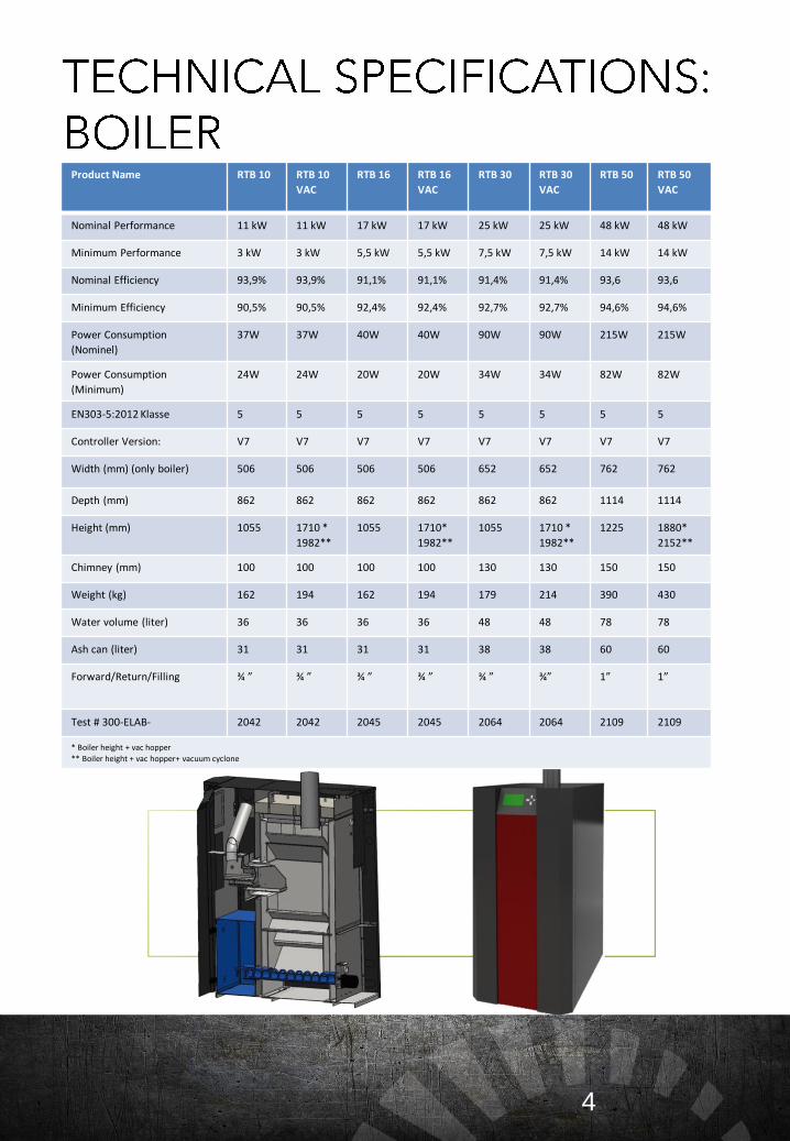
Nominal Performance 11 kW 11 kW 17 kW 17 kW 25 kW 25 kW 48 kW 48 kW
Minimum Performance 3 kW 3 kW 5,5 kW 5,5 kW 7,5 kW 7,5 kW 14 kW 14 kW
Nominal Efficiency 93,9% 93,9% 91,1% 91,1% 91,4% 91,4% 93,6 93,6
Minimum Efficiency 90,5% 90,5% 92,4% 92,4% 92,7% 92,7% 94,6% 94,6%
Power Consumption
(Nominel)
37W 37W 40W 40W 90W 90W 215W 215W
Power Consumption
(Minimum)
24W 24W 20W 20W 34W 34W 82W 82W
EN303-5:2012 Klasse 5 5 5 5 5 5 5 5
Controller Version: V7 V7 V7 V7 V7 V7 V7 V7
Width (mm) (only boiler) 506 506 506 506 652 652 762 762
Depth (mm) 862 862 862 862 862 862 1114 1114
Height (mm) 1055 1710 *
1982**
1055 1710*
1982**
1055 1710 *
1982**
1225 1880*
2152**
Chimney (mm) 100 100 100 100 130 130 150 150
Weight (kg) 162 194 162 194 179 214 390 430
Water volume (liter) 36 36 36 36 48 48 78 78
Ash can (liter) 31 31 31 31 38 38 60 60
Forward/Return/Filling ¾ ” ¾ ” ¾ ” ¾ ” ¾ ” ¾” 1” 1”
Test # 300-ELAB- 2042 2042 2045 2045 2064 2064 2109 2109
* Boiler height + vac hopper
** Boiler height + vac hopper+ vacuum cyclone
5
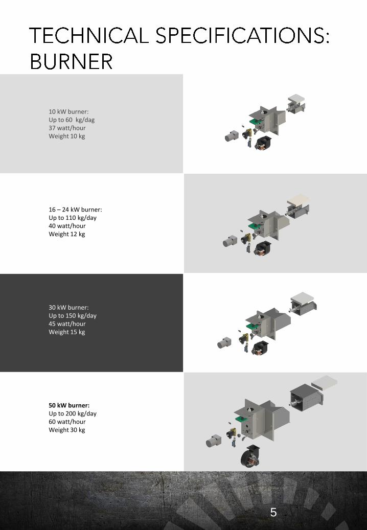
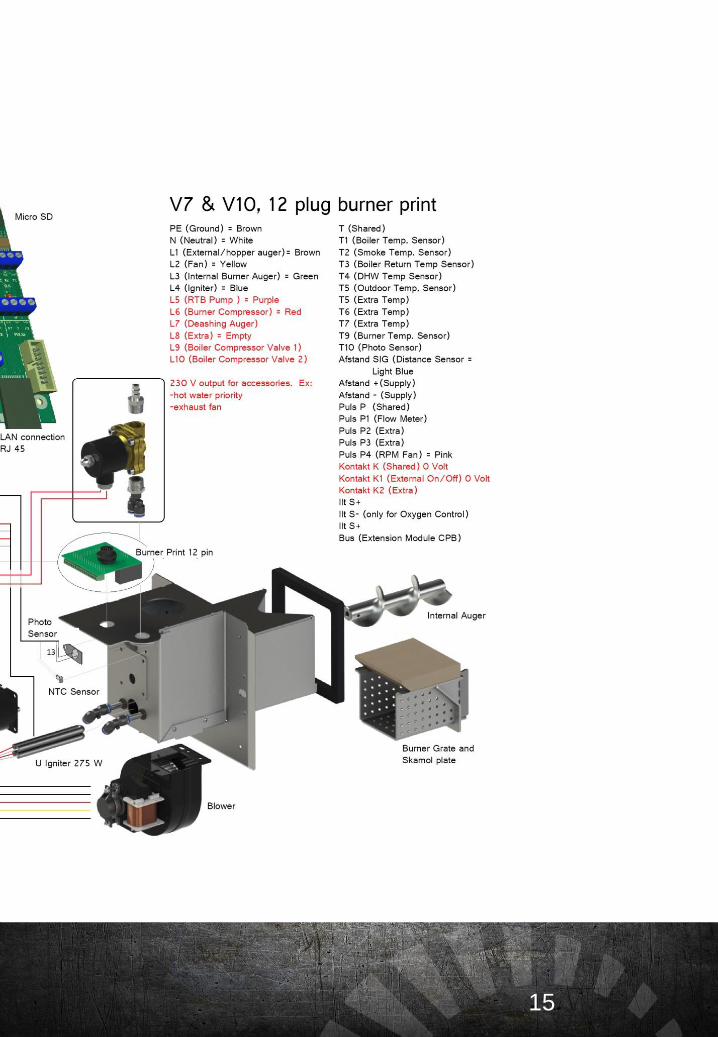
10 kW burner:Up to 60 kg/dag37 watt/hourWeight 10 kg
16 – 24 kW burner:Up to 110 kg/day40 watt/hourWeight 12 kg
30 kW burner:Up to 150 kg/day45 watt/hourWeight 15 kg
50 kW burner:Up to 200 kg/day60 watt/hourWeight 30 kg
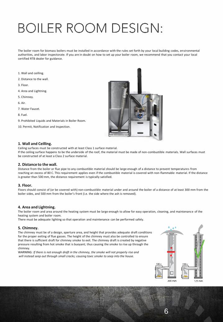
The boiler room for biomass boilers must be installed in accordance with the rules set forth by your local building codes, environmental authorities, and labor inspectorate. If you are in doubt on how to set up your boiler room, we recommend that you contact your local certified RTB dealer for guidance.
6
1. Wall and ceilling.
2. Distance to the wall.
3. Floor.
4. Area and Lightning.
5. Chimney.
6. Air.
7. Water Faucet.
8. Fuel.
9. Prohibited Liquids and Materials in Boiler Room.
10. Permit, Notification and Inspection.
1. Wall and Ceilling.Ceiling surfaces must be constructed with at least Class 1 surface material.If the ceiling surface happens to be the underside of the roof, the material must be made of non-combustible materials. Wall surfaces must be constructed of at least a Class 2 surface material.
2. Distance to the wall.Distance from the boiler or flue pipe to any combustible material should be large enough of a distance to prevent temperatures from reaching an excess of 80 C. This requirement applies even if the combustible material is covered with non-flammable material. If the distance is greater than 500 mm, the distance requirement is typically satisfied.
3. Floor.Floors should consist of (or be covered with) non-combustible material under and around the boiler of a distance of at least 300 mm from the boiler sides, and 500 mm from the boiler’s front (i.e. the side where the ash is removed).
4. Area and Lightning.The boiler room and area around the heating system must be large enough to allow for easy operation, cleaning, and maintenance of the heating system and boiler room.There must be adequate lighting so that operation and maintenance can be performed safely.
5. Chimney.The chimney must be of a design, aperture area, and height that provides adequate draft conditionsfor the proper exiting of flue gasses. The height of the chimney must also be controlled to ensure that there is sufficient draft for chimney smoke to exit. The chimney draft is created by negative pressure resulting from hot smoke that is buoyant; thus causing the smoke to rise up through thechimney. WARNING: If there is not enough draft in the chimney, the smoke will not properly rise andwill instead seep out through small cracks; causing toxic smoke to seep into the house.
The internal diameter of the chimney must be sufficient enough for the amount of flue gasses the chimney has to lead away. If the internal diameter is too small, this will prevent the smoke from exiting fast enough due to the large resistance in the chimney. This could cause the smoke to turn back; thus allowing for toxic fumes to enter into the house. Simultaneously, the pellet fuel may not be completely burned, due to the lack of oxygen for combustion. This can cause traces of tar like soot to sit in the chimney and create what is called creosote, which increases the risk of chimney fire.
The chimney opening must also not be too large since cold air can enter the chimney from the top. When the chimney becomes cooled, condensation can occur and develop soot inside the chimney. Soot is mostly a cosmetic problem, because it can penetrate through the chimney and cause ugly brown splotches to appear on the walls inside the house.
In addition, it is important that the chimney protrudes high enough above the roof so the smoke does not bother the surrounding houses. Environmental authorities have the possibility of prosecution if there are neighbors that complain about the smoke or odor.
7
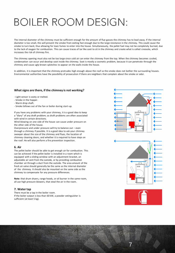
What signs are there, if the chimney is not working?
- Light sensor is sooty or melted.- Smoke in the hopper.- Warm drop shaft.- Smoke billows out of the fan or boiler during start-up.
If you have any problems with your chimney, it is a good idea to keep a ”diary” of any draft problem; as draft problems are often associated with wind in certain directions.Wind blowing on one side of the house can cause under pressure on the other side of the house.Overpressure and under pressure will try to balance out – even through a chimney if possible. It is a good idea to ask your chimney sweeper about the size of the chimney and flues, the location of chimney cleaning doors, and whether it is required to have steps on the roof. He will also perform a fire prevention inspection.
6. AirThe pellet boiler should be able to get enough air for combustion. This can be achieved if the pellet boiler is installed in a room which is equipped with a sliding window with an adjustment bracket, an adjustable air vent from the outside, or by providing combustion chamber air through a duct from the outside. The area amount of the fresh air valve should generally be the same as the internal diameter of the chimney. It should also be mounted on the same side as the chimney to compensate for any pressure differences.
Note: that drum dryers, range hoods, or oil burner in the same room, all use high pressure blowers, that steal the air in the room.
7. Water tapThere must be a tap in the boiler room.If the boiler output is less than 60 kW, a powder extinguisher is sufficient (at least 5 kg).
8
8. Fuel.The pellets must be pure wood, 6-8 mm, max. 8 % water. Materials with glue, paint, wood paint or plastics shall not be burned.If the fuel storage is greater than 0,75 m3, the boiler system and fuel storage must be located in a separate fire cell with at least one BD30 door to the other room.If the fuel storage or hopper is placed in the open or under a shelter, there may be minimum distances to the building that should be observed. Exposed fuel may not be in the boiler room, except logs. Do not exceed 4,75 m3 fuel in the boiler room, including fuel storage and usage storage.
9. Prohibited liquids and materials in boiler room.The boiler room must be kept clean and contain no combustible materials nor flammable liquids (except oil for oil burners).The floor must be kept free of spilled fuel, dust and combustible waste as well as waste from other activities in the room. Any burning embers must be extinguished with water and transported to a secure storage location in the open.
10. Permit, notification and inspection.Building permit:You must obtain building permit if the burner is situated in a building that is part of the Building Regulations 1995 (commercial buildings); though not for animals and farm buildings.
Notification:The heating system must be reported to the local council and registered with the chimney sweep.
Inspection:The chimney sweeper will regularly supervise your biofuel boiler. If the chimney sweeper becomes aware of any illegality under the rules for fireplaces and chimneys in the building code, he may notify the local council if the owner does not change the illegal conduct.
Insurance:You must notify your insurance company about your biomass system.
!
9
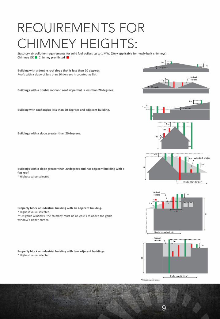
Building with a double roof slope that is less than 20 degrees.Roofs with a slope of less than 20 degrees is counted as flat.
Buildings with a double roof and roof slope that is less than 20 degrees.
Building with roof angles less than 20 degrees and adjacent building.
Buildings with a slope greater than 20 degrees.
Buildings with a slope greater than 20 degrees and has adjacent building with a flat roof.* Highest value selected.
Property block or industrial building with an adjacent building.* Highest value selected.** At gable windows, the chimney must be at least 1 m above the gable window’s upper corner.
Property block or industrial building with two adjacent buildings.* Highest value selected.
Statutory air pollution requirements for solid fuel boilers up to 1 MW. (Only applicable for newly-built chimneys). Chimney OK Chimney prohibited
10
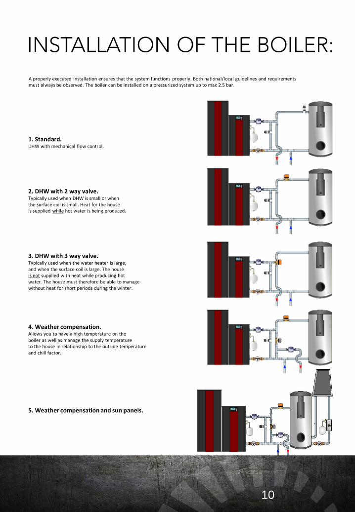
1. Standard.DHW with mechanical flow control.
2. DHW with 2 way valve.Typically used when DHW is small or when the surface coil is small. Heat for the house is supplied while hot water is being produced.
3. DHW with 3 way valve.Typically used when the water heater is large, and when the surface coil is large. The house is not supplied with heat while producing hot water. The house must therefore be able to manage without heat for short periods during the winter.
4. Weather compensation.Allows you to have a high temperature on the boiler as well as manage the supply temperature to the house in relationship to the outside temperature and chill factor.
5. Weather compensation and sun panels.
A properly executed installation ensures that the system functions properly. Both national/local guidelines and requirements must always be observed. The boiler can be installed on a pressurized system up to max 2.5 bar.
11
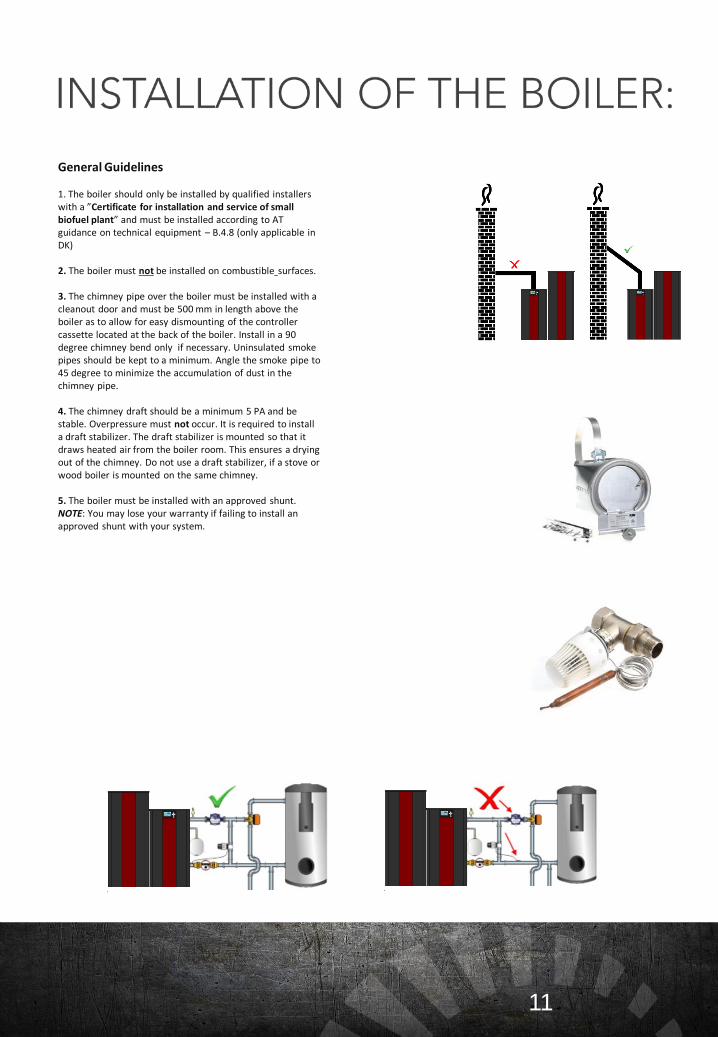
General Guidelines
1. The boiler should only be installed by qualified installers with a ”Certificate for installation and service of small biofuel plant” and must be installed according to AT guidance on technical equipment – B.4.8 (only applicable in DK)
2. The boiler must not be installed on combustible surfaces.
3. The chimney pipe over the boiler must be installed with a cleanout door and must be 500 mm in length above the boiler as to allow for easy dismounting of the controller cassette located at the back of the boiler. Install in a 90 degree chimney bend only if necessary. Uninsulated smoke pipes should be kept to a minimum. Angle the smoke pipe to 45 degree to minimize the accumulation of dust in the chimney pipe.
4. The chimney draft should be a minimum 5 PA and be stable. Overpressure must not occur. It is required to install a draft stabilizer. The draft stabilizer is mounted so that it draws heated air from the boiler room. This ensures a drying out of the chimney. Do not use a draft stabilizer, if a stove or wood boiler is mounted on the same chimney.
5. The boiler must be installed with an approved shunt. NOTE: You may lose your warranty if failing to install an approved shunt with your system.
12
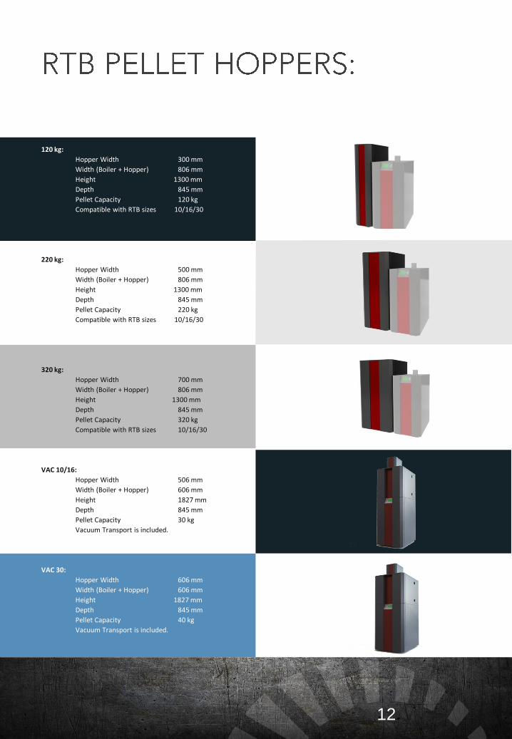
120 kg:
Hopper Width 300 mm
Width (Boiler + Hopper) 806 mm
Height 1300 mm
Depth 845 mm
Pellet Capacity 120 kg
Compatible with RTB sizes 10/16/30
220 kg:
Hopper Width 500 mm
Width (Boiler + Hopper) 806 mm
Height 1300 mm
Depth 845 mm
Pellet Capacity 220 kg
Compatible with RTB sizes 10/16/30
320 kg:
Hopper Width 700 mm
Width (Boiler + Hopper) 806 mm
Height 1300 mm
Depth 845 mm
Pellet Capacity 320 kg
Compatible with RTB sizes 10/16/30
VAC 10/16:
Hopper Width 506 mm
Width (Boiler + Hopper) 606 mm
Height 1827 mm
Depth 845 mm
Pellet Capacity 30 kg
Vacuum Transport is included.
VAC 30:
Hopper Width 606 mm
Width (Boiler + Hopper) 606 mm
Height 1827 mm
Depth 845 mm
Pellet Capacity 40 kg
Vacuum Transport is included.
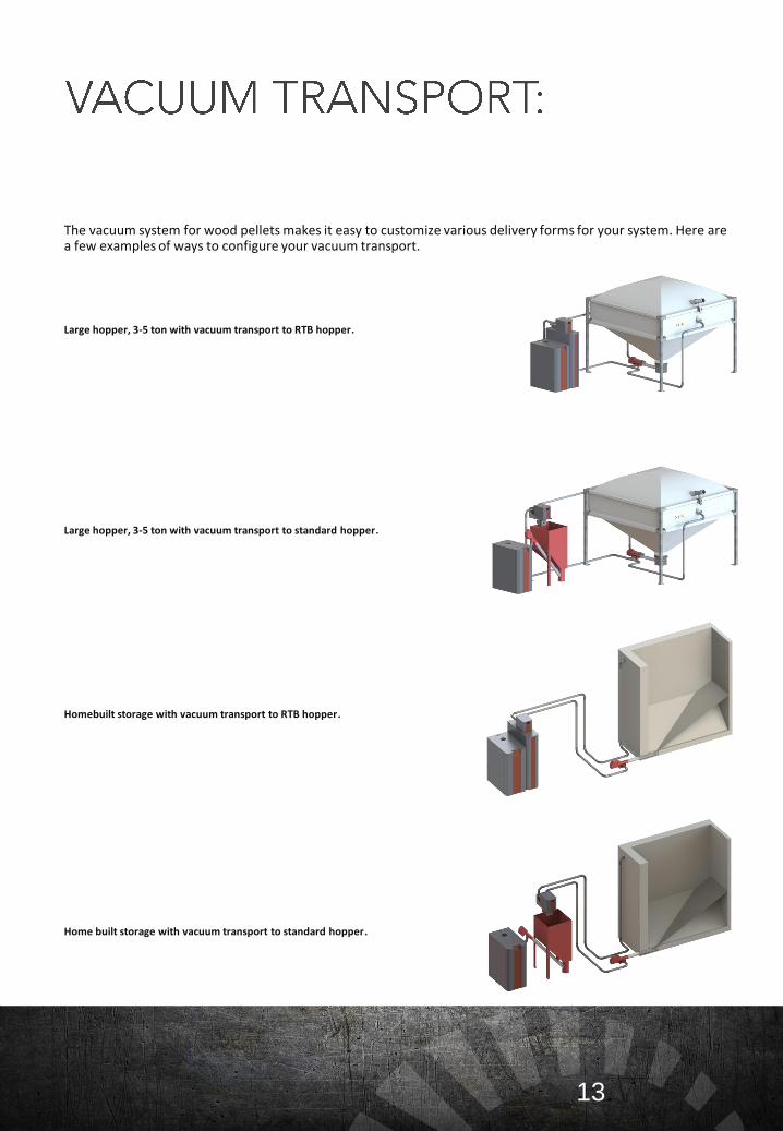
The vacuum system for wood pellets makes it easy to customize various delivery forms for your system. Here are a few examples of ways to configure your vacuum transport.
Large hopper, 3-5 ton with vacuum transport to RTB hopper.
Large hopper, 3-5 ton with vacuum transport to standard hopper.
Homebuilt storage with vacuum transport to RTB hopper.
Home built storage with vacuum transport to standard hopper.
13
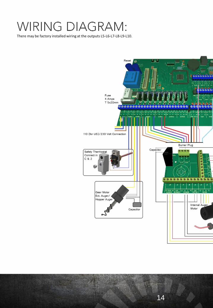
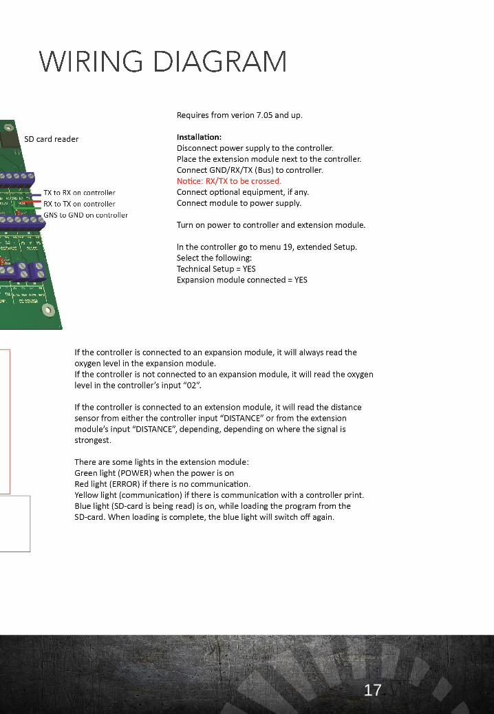
There may be factory installed wiring at the outputs L5-L6-L7-L8-L9-L10.
14
15
16
17
18
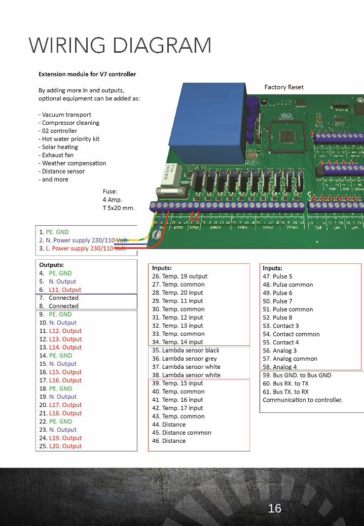
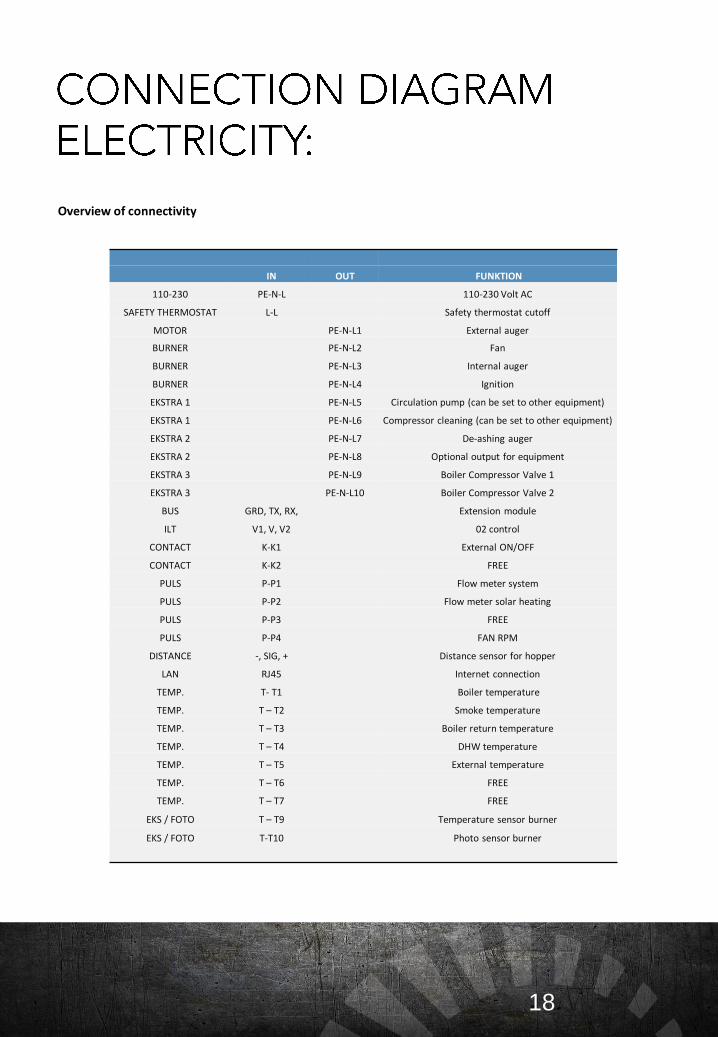
Overview of connectivity
IN OUT FUNKTION
110-230 PE-N-L 110-230 Volt AC
SAFETY THERMOSTAT L-L Safety thermostat cutoff
MOTOR PE-N-L1 External auger
BURNER PE-N-L2 Fan
BURNER PE-N-L3 Internal auger
BURNER PE-N-L4 Ignition
EKSTRA 1 PE-N-L5 Circulation pump (can be set to other equipment)
EKSTRA 1 PE-N-L6 Compressor cleaning (can be set to other equipment)
EKSTRA 2 PE-N-L7 De-ashing auger
EKSTRA 2 PE-N-L8 Optional output for equipment
EKSTRA 3 PE-N-L9 Boiler Compressor Valve 1
EKSTRA 3 PE-N-L10 Boiler Compressor Valve 2
BUS GRD, TX, RX, Extension module
ILT V1, V, V2 02 control
CONTACT K-K1 External ON/OFF
CONTACT K-K2 FREE
PULS P-P1 Flow meter system
PULS P-P2 Flow meter solar heating
PULS P-P3 FREE
PULS P-P4 FAN RPM
DISTANCE -, SIG, + Distance sensor for hopper
LAN RJ45 Internet connection
TEMP. T- T1 Boiler temperature
TEMP. T – T2 Smoke temperature
TEMP. T – T3 Boiler return temperature
TEMP. T – T4 DHW temperature
TEMP. T – T5 External temperature
TEMP. T – T6 FREE
TEMP. T – T7 FREE
EKS / FOTO T – T9 Temperature sensor burner
EKS / FOTO T-T10 Photo sensor burner
19
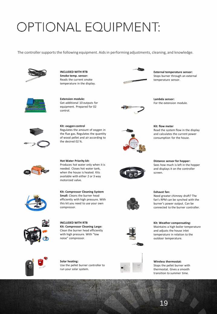
The controller supports the following equipment. Aids in performing adjustments, cleaning, and knowledge.
INCLUDED WITH RTBSmoke temp. sensor:Reads the current smoke temperature in the display.
Extension module:Get additional 10 outputs for equipment. Prepared for 02 control.
Kit: oxygen controlRegulates the amount of oxygen in the flue gas. Regulates the quantity of wood pellet and air according to the desired 02 %.
Hot Water Priority kit:Produces hot water only when it is needed. Closes hot water tank, when the house is heated. Kits available with either 2 or 3 way motorized valve.
Kit: Compressor Cleaning System Small: Cleans the burner head efficiently with high pressure. With this kit you need to use your own compressor.
INCLUDED WITH RTBKit: Compressor Cleaning Large:Clean the burner head efficiently with high pressure. With ”low noise” compressor.
Solar heating:Use the pellet burner controller to run your solar system.
External temperature sensor:Stops burner through an external temperature sensor.
Lambda sensor:For the extension module.
Kit: flow meterRead the system flow in the display and calculates the current power consumption for the house.
Distance sensor for hopper:Sees how much is left in the hopper and displays it on the controller screen.
Exhaust fan:Need greater chimney draft? The fan’s RPM can be synched with the burner’s power output. Can be connected to the burner controller.
Kit: Weather compensating:Maintains a high boiler temperature and adjusts the house inlet temperature in relation to the outdoor temperature.
Wireless thermostat:Stops the pellet burner with thermostat. Gives a smooth transition to summer time.
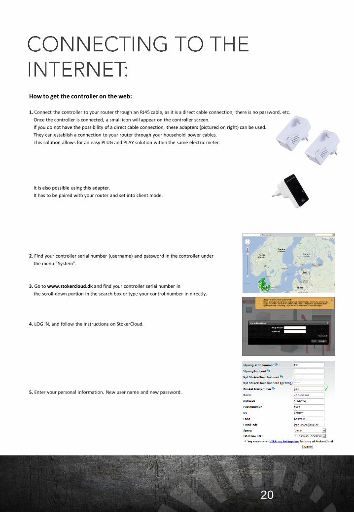
How to get the controller on the web:
1. Connect the controller to your router through an RJ45 cable, as it is a direct cable connection, there is no password, etc.
Once the controller is connected, a small icon will appear on the controller screen.
If you do not have the possibility of a direct cable connection, these adapters (pictured on right) can be used.
They can establish a connection to your router through your household power cables.
This solution allows for an easy PLUG and PLAY solution within the same electric meter.
It is also possible using this adapter.
It has to be paired with your router and set into client mode.
2. Find your controller serial number (username) and password in the controller under
the menu ”System”.
3. Go to www.stokercloud.dk and find your controller serial number in
the scroll-down portion in the search box or type your control number in directly.
4. LOG IN, and follow the instructions on StokerCloud.
5. Enter your personal information. New user name and new password.
20
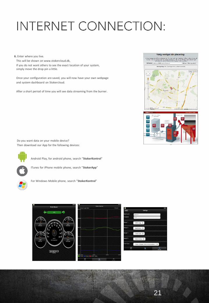
6. Enter where you live.
This will be shown on www.stokercloud.dk,
If you do not want others to see the exact location of your system, simply move the drop pin a little.
Once your configuration are saved, you will now have your own webpage
and system dashboard on Stokercloud.
After a short period of time you will see data streaming from the burner.
Do you want data on your mobile device?
Then download our App for the following devices:
Android Play, for android phone, search ”StokerKontrol”
ITunes for iPhone mobile phone, search ”StokerApp”
For Windows Mobile phone, search ”StokerKontrol”
21
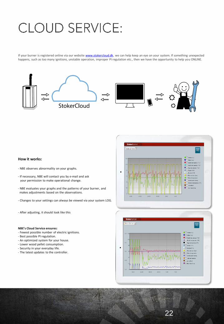
If your burner is registered online via our website www.stokercloud.dk, we can help keep an eye on your system. If something unexpected happens, such as too many ignitions, unstable operation, improper PI regulation etc., then we have the opportunity to help you ONLINE.
How it works:
- NBE observes abnormality on your graphs.
- If necessary, NBE will contact you by e-mail and ask your permission to make operational change.
- NBE evaluates your graphs and the patterns of your burner, andmakes adjustments based on the observations.
- Changes to your settings can always be viewed via your system LOG.
- After adjusting, it should look like this
NBE’s Cloud Service ensures:- Fewest possible number of electric ignitions.- Best possible PI regulation.- An optimized system for your house.- Lower wood pellet consumption.- Security in your everyday life.- The latest updates to the controller.
22
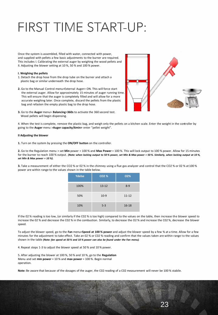
Once the system is assembled, filled with water, connected with power, and supplied with pellets a few basic adjustments to the burner are required. This includes I. Calibrating the external auger by weighing the wood pellets and II. Adjusting the blower setting at 10 %, 50 % and 100 % power.
I. Weighing the pellets1. Detach the drop hose from the drop tube on the burner and attach a
plastic bag or similar underneath the drop hose.
2. Go to the Manual Control menu>External Auger> ON. This will force start the external auger. Allow for approximately 15 minutes of auger running time. This will ensure that the auger is completely filled and will allow for a more accurate weighing later. Once complete, discard the pellets from the plastic bag and refasten the empty plastic bag to the drop hose.
3. Go to the Auger menu> Balancing>360s to activate the 360 second test. Wood pellets will begin dispensing.
4. When the test is complete, remove the plastic bag, and weigh only the pellets on a kitchen scale. Enter the weight in the controller by going to the Auger menu >Auger capacity/6min> enter “pellet weight”.
II Adjusting the blower
1. Turn on the system by pressing the ON/OFF button on the controller.
2. Go to the Regulation menu > set Min power = 100 % and Max Power = 100 %. This will lock output to 100 % power. Allow for 15 minutes for the burner to reach 100 % output. (Note: when locking output to 50 % power, set Min & Max power = 50 %. Similarly, when locking output at 10 %, set Min & Max power = 10 %).
3. Take a measurement of either the CO2 % or 02 % in the chimney using a flue gas analyzer and control that the CO2 % or 02 % at 100 % power are within range to the values shown in the table below.
If the 02 % reading is too low, (or similarly if the C02 % is too high) compared to the values on the table, then increase the blower speed to increase the 02 % and decrease the C02 % in the combustion. Similarly, to decrease the O2 % and increase the C02 %, decrease the blower speed.
To adjust the blower speed, go to the Fan menu>Speed at 100 % power and adjust the blower speed by a few % at a time. Allow for a few minutes for the adjustment to take effect. Take an 02 % or C02 % reading and confirm that the values taken are within range to the values shown in the table (Note: fan speed at 50 % and 10 % power can also be found under the Fan menu).
4. Repeat steps 1-3 to adjust the blower speed at 50 % and 10 % power.
5. After adjusting the blower at 100 %, 50 % and 10 %, go to the RegulationMenu and set min power = 10 % and max power = 100 %. Begin normal operation.
Note: Be aware that because of the dosages of the auger, the C02 reading of a C02 measurement will never be 100 % stabile.
KUNDEN bør vejledes i hvordan man afvejer sneglen og justerer autoberegningen .Skal foretages efter behov og ved skift af træpiller !
23
Ydelse CO2 % O2%
100% 13-12 8-9
50% 10-9 11-12
10% 5-3 16-18
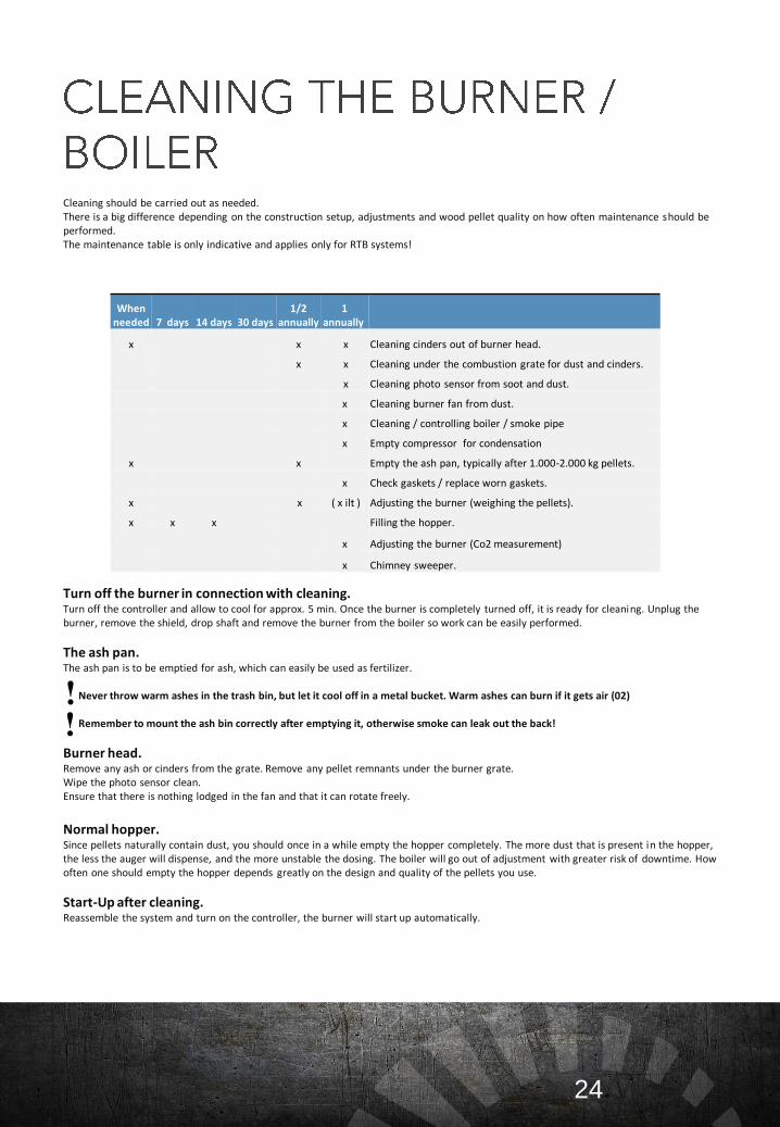
Cleaning should be carried out as needed. There is a big difference depending on the construction setup, adjustments and wood pellet quality on how often maintenance should be performed. The maintenance table is only indicative and applies only for RTB systems!
Turn off the burner in connection with cleaning.Turn off the controller and allow to cool for approx. 5 min. Once the burner is completely turned off, it is ready for cleaning. Unplug the burner, remove the shield, drop shaft and remove the burner from the boiler so work can be easily performed.
The ash pan.The ash pan is to be emptied for ash, which can easily be used as fertilizer.
Never throw warm ashes in the trash bin, but let it cool off in a metal bucket. Warm ashes can burn if it gets air (02)
Remember to mount the ash bin correctly after emptying it, otherwise smoke can leak out the back!
Burner head.Remove any ash or cinders from the grate. Remove any pellet remnants under the burner grate. Wipe the photo sensor clean. Ensure that there is nothing lodged in the fan and that it can rotate freely.
Normal hopper.Since pellets naturally contain dust, you should once in a while empty the hopper completely. The more dust that is present in the hopper, the less the auger will dispense, and the more unstable the dosing. The boiler will go out of adjustment with greater risk of downtime. How often one should empty the hopper depends greatly on the design and quality of the pellets you use.
Start-Up after cleaning.Reassemble the system and turn on the controller, the burner will start up automatically.
24
When needed 7 days 14 days 30 days
1/2 annually
1 annually
x x x Cleaning cinders out of burner head.
x x Cleaning under the combustion grate for dust and cinders.
x Cleaning photo sensor from soot and dust.
x Cleaning burner fan from dust.
x Cleaning / controlling boiler / smoke pipe
x Empty compressor for condensation
x x Empty the ash pan, typically after 1.000-2.000 kg pellets.
x Check gaskets / replace worn gaskets.
x x ( x ilt ) Adjusting the burner (weighing the pellets).
x x x Filling the hopper.
x Adjusting the burner (Co2 measurement)
x Chimney sweeper.
!!
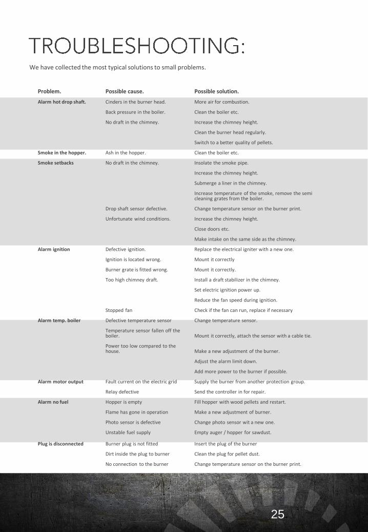
We have collected the most typical solutions to small problems.
25
Problem. Possible cause. Possible solution.
Alarm hot drop shaft. Cinders in the burner head. More air for combustion.
Back pressure in the boiler. Clean the boiler etc.
No draft in the chimney. Increase the chimney height.
Clean the burner head regularly.
Switch to a better quality of pellets.
Smoke in the hopper. Ash in the hopper. Clean the boiler etc.
Smoke setbacks No draft in the chimney. Insolate the smoke pipe.
Increase the chimney height.
Submerge a liner in the chimney.
Increase temperature of the smoke, remove the semi cleaning grates from the boiler.
Drop shaft sensor defective. Change temperature sensor on the burner print.
Unfortunate wind conditions. Increase the chimney height.
Close doors etc.
Make intake on the same side as the chimney.
Alarm ignition Defective ignition. Replace the electrical igniter with a new one.
Ignition is located wrong. Mount it correctly
Burner grate is fitted wrong. Mount it correctly.
Too high chimney draft. Install a draft stabilizer in the chimney.
Set electric ignition power up.
Reduce the fan speed during ignition.
Stopped fan Check if the fan can run, replace if necessary
Alarm temp. boiler Defective temperature sensor Change temperature sensor.
Temperature sensor fallen off the boiler. Mount it correctly, attach the sensor with a cable tie.
Power too low compared to the house. Make a new adjustment of the burner.
Adjust the alarm limit down.
Add more power to the burner if possible.
Alarm motor output Fault current on the electric grid Supply the burner from another protection group.
Relay defective Send the controller in for repair.
Alarm no fuel Hopper is empty Fill hopper with wood pellets and restart.
Flame has gone in operation Make a new adjustment of burner.
Photo sensor is defective Change photo sensor wit a new one.
Unstable fuel supply Empty auger / hopper for sawdust.
Plug is disconnected Burner plug is not fitted Insert the plug of the burner
Dirt inside the plug to burner Clean the plug for pellet dust.
No connection to the burner Change temperature sensor on the burner print.
26
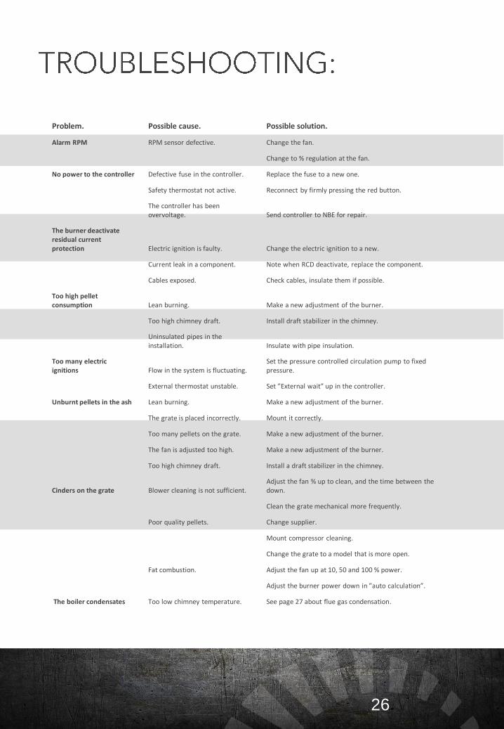
Problem. Possible cause. Possible solution.
Alarm RPM RPM sensor defective. Change the fan.
Change to % regulation at the fan.
No power to the controller Defective fuse in the controller. Replace the fuse to a new one.
Safety thermostat not active. Reconnect by firmly pressing the red button.
The controller has been overvoltage. Send controller to NBE for repair.
The burner deactivate residual current protection Electric ignition is faulty. Change the electric ignition to a new.
Current leak in a component. Note when RCD deactivate, replace the component.
Cables exposed. Check cables, insulate them if possible.
Too high pellet consumption Lean burning. Make a new adjustment of the burner.
Too high chimney draft. Install draft stabilizer in the chimney.
Uninsulated pipes in the installation. Insulate with pipe insulation.
Too many electric ignitions Flow in the system is fluctuating.
Set the pressure controlled circulation pump to fixed pressure.
External thermostat unstable. Set ”External wait” up in the controller.
Unburnt pellets in the ash Lean burning. Make a new adjustment of the burner.
The grate is placed incorrectly. Mount it correctly.
Too many pellets on the grate. Make a new adjustment of the burner.
The fan is adjusted too high. Make a new adjustment of the burner.
Too high chimney draft. Install a draft stabilizer in the chimney.
Cinders on the grate Blower cleaning is not sufficient.Adjust the fan % up to clean, and the time between the down.
Clean the grate mechanical more frequently.
Poor quality pellets. Change supplier.
Mount compressor cleaning.
Change the grate to a model that is more open.
Fat combustion. Adjust the fan up at 10, 50 and 100 % power.
Adjust the burner power down in ”auto calculation”.
The boiler condensates Too low chimney temperature. See page 27 about flue gas condensation.
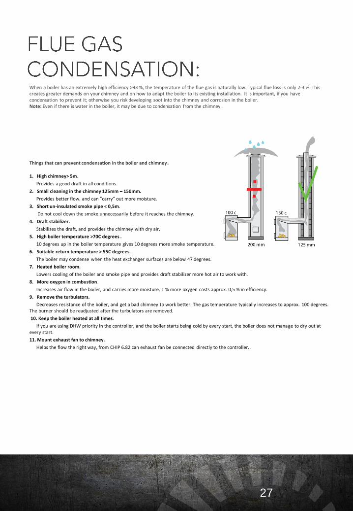
When a boiler has an extremely high efficiency >93 %, the temperature of the flue gas is naturally low. Typical flue loss is only 2-3 %. This creates greater demands on your chimney and on how to adapt the boiler to its existing installation. It is important, if you have condensation to prevent it; otherwise you risk developing soot into the chimney and corrosion in the boiler. Note: Even if there is water in the boiler, it may be due to condensation from the chimney.
Things that can prevent condensation in the boiler and chimney.
1. High chimney> 5m.
Provides a good draft in all conditions.
2. Small cleaning in the chimney 125mm – 150mm.
Provides better flow, and can ”carry” out more moisture.
3. Short un-insulated smoke pipe < 0,5m.
Do not cool down the smoke unnecessarily before it reaches the chimney.
4. Draft stabilizer.
Stabilizes the draft, and provides the chimney with dry air.
5. High boiler temperature >70C degrees .
10 degrees up in the boiler temperature gives 10 degrees more smoke temperature.
6. Suitable return temperature > 55C degrees.
The boiler may condense when the heat exchanger surfaces are below 47 degrees.
7. Heated boiler room.
Lowers cooling of the boiler and smoke pipe and provides draft stabilizer more hot air to work with.
8. More oxygen in combustion.
Increases air flow in the boiler, and carries more moisture, 1 % more oxygen costs approx. 0,5 % in efficiency.
9. Remove the turbulators.
Decreases resistance of the boiler, and get a bad chimney to work better. The gas temperature typically increases to approx. 100 degrees. The burner should be readjusted after the turbulators are removed.
10. Keep the boiler heated at all times.
If you are using DHW priority in the controller, and the boiler starts being cold by every start, the boiler does not manage to dry out at every start.
11. Mount exhaust fan to chimney.
Helps the flow the right way, from CHIP 6.82 can exhaust fan be connected directly to the controller..
27
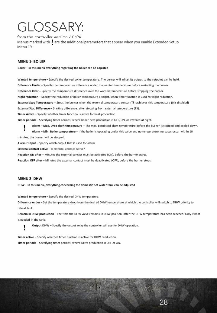
MENU 1- BOILER
Boiler – in this menu everything regarding the boiler can be adjusted
Wanted temperature – Specify the desired boiler temperature. The burner will adjust its output to the setpoint can be held.
Difference Under – Specify the temperature difference under the wanted temperature before restarting the burner.
Difference Over – Specify the temperature difference over the wanted temperature before stopping the burner.
Night reduction – Specify the reduction of boiler temperature at night, when timer function is used for night reduction.
External Stop Temperature – Stops the burner when the external temperature sensor (T5) achieves this temperature (0 is disabled)
External Stop Difference – Starting difference, after stopping from external temperature (T5).
Timer Active – Specify whether timer function is active for heat production.
Timer periods – Specifying timer periods, where boiler heat production is OFF, ON, or lowered at night.
Alarm – Max. Drop shaft temperature – The max. permitted shaft temperature before the burner is stopped and cooled down.
Alarm – Min. Boiler temperature – If the boiler is operating under this value and no temperature increases occur within 10
minutes, the burner will be stopped.
Alarm Output – Specify which output that is used for alarm.
External contact active – Is external contact active?
Reaction ON after – Minutes the external contact must be activated (ON), before the burner starts.
Reaction OFF after – Minutes the external contact must be deactivated (OFF), before the burner stops.
MENU 2- DHW
DHW – In this menu, everything concerning the domestic hot water tank can be adjusted
Wanted temperature – Specify the desired DHW temperature.
Difference under – Set the temperature drop from the desired DHW temperature at which the controller will switch to DHW priority to
reheat tank.
Remain in DHW production – The time the DHW valve remains in DHW position, after the DHW temperature has been reached. Only if heat
is needed in the tank.
Output DHW – Specify the output relay the controller will use for DHW operation.
Timer active – Specify whether timer function is active for DHW production.
Timer periods – Specifying timer periods, where DHW production is OFF or ON.
Menus marked with are the additional parameters that appear when you enable Extended Setup Menu 19.
28
!
!
!
MENU 3 - REGULATION
Regulation – in this menu, everything concerning the PI regulation can be adjusted.
Temperature regulation gain P – Note: Responds to boiler temperature change. The higher the value, the greater the response.
Temperature regulation gain I – Note: Responds to boiler temperature differences over time. The longer the time, the greater the
response.
Power increase / minute – Specify the maximum output increase per minute after the start-up.
Min. power – Minimum power in percent. Not valid for DHW mode, which is set in the parameter Min. Power at DHW – see 3.6.
Max. power – Maximum power in percent. Not valid for DHW mode, which is set in the parameter Max. Power at DHW – see 3.6.
DHW regulation gain P – Response to DHW temperature change. The higher the value, the greater the response.
DHW regulation gain I – Response to DHW temperature difference over time. The higher the value, the greater the response.
Setpoint boiler addition – Setpoint at DHW production is the wanted DHW temperature plus this addition.
Min. Power – Specifying min. output doing DHW, can be increased DHW production is too slow.
Max power at DHW – Specify the max. Burner output during DHW operation. This can be reduced if the boiler overheats doing DHW
operation.
29
!
!
MENU 4 – WEATHER
Weather – In this menu, everything concerning weather compensation can be adjusted. Ex. Operation via the outdoor temperature.
Active – Activate weather compensation?
Mean period temperature – The measured temperature used, is the average temperature over this period of time (hours).
Use T5 temperature sensor – Specify if the temperature is to be read from a local sensor or the internet.
Chill factor weight – Weight (%) of registered chill factor. Use for example if exposed to abnormal wind conditions.
Valve at DHW production – Valve reaction at DHW production. If the DHW is placed on the weather compensated circuit, choose
100 open (open valve)
Outlet house pump – Specify which output is to be used for the house pump.
Regulating valve open – Specify which output on the controller to use for opening regulating valve.
Regulating valve close – Specify which output on the controller to use for closing regulating valve.
Gain P – Specify the response to house temperature changes. The higher the value, the greater the response.
Measured temperature 1 – Specify the temperature for regulation at point 1. At this temperature the burner will stop.
Measured temperature 2 – Specify the temperature for regulation at point 2. At this temperature the burner will stop.
Measured temperature 3 – Specify the temperature for regulation at point 3. At this temperature the burner will stop.
Measured temperature 4 – Specify the temperature for regulation at point 4. At this temperature the burner will stop.
Measured temperature 5 – Specify the temperature for regulation at point 5. At this temperature the burner will stop.
Measured temperature 6 – Specify the temperature for regulation at point 6. At this temperature the burner will stop.
Measured temperature 7 – Specify the temperature for regulation at point 7. At this temperature the burner will stop.
Forward temperature 1 – Enter the wanted temperature for regulation at point 1.
Forward temperature 2 – Enter the wanted temperature for regulation at point 2.
Forward temperature 3 – Enter the wanted temperature for regulation at point 3.
Forward temperature 4 – Enter the wanted temperature for regulation at point 4.
Forward temperature 5 – Enter the wanted temperature for regulation at point 5.
Forward temperature 6 – Enter the wanted temperature for regulation at point 6.
Forward temperature 7 – Enter the wanted temperature for regulation at point 7.
Max. Power 1 – Enter the wanted power for regulation at point 1.
Max. Power 2 – Enter the wanted power for regulation at point 2.
Max. Power 3 – Enter the wanted power for regulation at point 3.
Max. Power 4 – Enter the wanted power for regulation at point 4.
Max. Power 5 – Enter the wanted power for regulation at point 5.
Max. Power 6 – Enter the wanted power for regulation at point 6.
Max. Power 7 – Enter the wanted power for regulation at point 7.
30
!
MENU 5- 02 CONTROL
O2 Control – In this menu, everything concerning the 02 control can be adjusted.
O2 control method – Specify if 02 control is active (ON), not active (OFF) or 02 is shown but not regulated (SHOW).
Wanted O2 at 10% power – Specify the desired % oxygen in the boiler at 10 % power.
Wanted 02 at 50 % power – Specify the desired % oxygen in the boiler at 50 % power.
Wanted 02 at 100 % power – Specify the desired % oxygen in the boiler at 100 % power.
O2 probe calibration – Start calibration of 02 probe
Wood pellet blocking time – Specify the number of minutes prior to blocking the pellet fuel when actual 02 % < 2 % lower than
the desired 02%
Updating time – Specify how often the 02 controller is allowed to make an adjustment on the flower speed and the fuel.
Regulation gain P – Specify how much the controller should respond to temperature changes.
Regulation gain I – Specify how much the controller should respond to time away from the desired oxygen content.
Correction fan 10 % - Specify how much the 02 controller can regulate the fan speed at 10 % power (plus, minus).
Correction fan 50 % - Specify how much the 02 controller can regulate the fan speed at 50 % power (plus, minus).
Correction fan 100 % - Specify how much the 02 controller can regulate the fan speed at 100 % power (plus, minus).
Regulation pellets gain P – Specifies gain for proportional oxygen regulation of wood pellets.
Regulation pellets gain I – Specifies gain for integrated oxygen regulation of wood pellets.
02 sensor type – Specify type of attached lambda sensor
02 sensor on expansion module – Is the oxygen sensor (lambda sensor) connected to an expansion module?
MENU 6 – CLEANING
Cleaning – In this menu, everything concerning cleaning can be adjusted.
Time between – Specify how often the fan should increase in speed to clean out the burner grate.
Time – Specify the duration of time desired for regular cleaning by the fan. Note: the fan will speed up to clean the grate.
Speed – Specify the fan speed to be used during regular cleaning.
Cleaning after – Specify the interval (lbs) between compressor cleaning. Note: A run period will always end with a cleaning.
Valve operating period – During this period, the air valve repeatedly opens for 0,2 sec and closes for 1,8 seconds.
Valve pulse length – Specify the air valve opening time of the total period of 2 seconds.
Stop pellets for – Specify the time desired to pause pellet dosing prior to cleaning. Note: ensures the wood pellets burn out.
Fan speed – Specify the fan speed desired when performing compressor cleaning.
Output valve – Specify the output relay in the controller that the valve is connected to.
Outlet boiler valve 1 – Specify the output for cleaning system valve 1. Activates half the time of compressor valve.
Outlet boiler valve 2 – Specify the output for cleaning system valve 2. Activates half the time of compressor valve.
Outlet ash auger – Activates the ash cleaning system. Runs 2 minutes for each 50 lbs pellets consumed.
Measure compressed air on T7 – Specifies if T7 is used for measuring of compressed air. If not, T7 can be used as
temperature sensor input.
31
!
!
MENU 7 – HOPPER
Hopper – In this menu, everything concerning the wood pellet hopper can be adjusted.
Distance top – Enter the distance from the sensor to the top of the pellets when the hopper is full. (minimum 2 in).
Distance bottom – Enter the distance from the sensor to the bottom of the pellets (cm) when the hopper is empty.
Automatic fill – Enter the number of lbs of pellets in the hopper when full. Note: values will be put into hopper content automatically.
Hopper content – Enter the hopper content (lbs). Note: this values is used for counting down the amount of pellets.
Minimum hopper content – Specify the minimum content of the hopper. An info-message is issued when this level is reached.
MENU 8 - FAN
Fan – In this menu, everything concerning the fan can be adjusted.
Speed at 10 % power – Fan speed at 10 % power must be adjusted according to the fuel, chimney draft, and back pressure in the boiler.
Speed at 50 % power – Fan speed at 50 % power must be adjusted according to the fuel, chimney draft, and back pressure in the boiler.
Speed at 100 % power – Fan speed at 100 % power must be adjusted according to the fuel, chimney draft, and back pressure in the boiler.
Use fan RPM – Select regulation of fan speed in Round Per Minute (RPM).
Use fan RPM alarm –
Exhaust fan: Speed at 10 % power – Wanted speed on exhaust fan, when the burner has 10 % output.
Exhaust fan: Speed at 50 % power – Wanted speed on exhaust fan, when the burner has 50 % output.
Exhaust fan: Speed at 100 % power – Wanted speed on exhaust fan, when the burner has 100 % output.
Controller output exhaust fan – Specify which output that is used for exhaust fan.
MENU 9 - AUGER
Auger – In this menu, everything concerning the external auger can be adjusted.
Force run external auger – Enter the number of seconds used for forced-running of the external auger. Use for auto calculation or for refilling
the auger.
Balancing – Do you want to measure external auger capacity for 6 minutes?
Auger capacity/6 min – Used to calculate the wood pellet quantity at 10 % and 100 % power.
Auto combustion – Choose if the controller calculates external auger time?
Auger feed time 10 % - Enter the auger running time at 10 % power (two decimals), only active if auto combustion is OFF.
Auger feed time 50 % - Enter the auger running time at 50 % (two decimals), only active if auto combustion is OFF
Auger feed time 100 % - Enter the auger running time at 100 % (two decimals), only active if auto combustion is OFF
Min. output at 10 % – Minimum output on the burner. Must be adjusted according to the size of the burner and the draft in the
chimney.
Max. Output Btu – Note: the nominal effect of the burner must match the boiler’s and burner’s rated output. Used in auto
combustion.
Auger feed times/minute – Specify number of times/minute you would like the internal auger to e dosing pellets. Note: does not
change the quantity.
Minimum pellets dose – Specify the minimum pellets dose each time the external auger feeds pellets.
32
!
!
Menu 10 - Ignition
Ignition – In this menu, everything concerning the ignition can be adjusted.
Pellets for ignition – Specify the amount of wood pellet to be used during ignition. Note: less quantity less smoke during start-up.
Ignition power – Specify the desired electrical load of the igniter. Note: the lower the load %, the longer the durability.
Fan speed start – Specify the desired fan speed at the start of an ignition cycle.
Fan speed middle – Specify the desired fan speed in the middle of an ignition cycle.
Fan speed end – Specify the desired fan speed at the end of an ignition cycle.
Max Time – Specifying the maximum time an electrical ignition can take. Note: the fan speed will change over this period of time.
Preheating – Specify the preheating time desired for the igniter. Note: specifies the time prior to the blower cycle.
Exhaust fan speed – Specify the amount of wood pellet to be used during ignition.
Number of ignitions – Specify the number of ignitions made. Can be cleared using the function - Reset ignition data
Reset ignition data – Reset the ignition counter. Ex. Use when replacing the igniter Note: A typical system should ignite 1000 times/year.
Menu 11 - Pump
Pump – In this menu, everything concerning the circulation pump can be adjusted.
Start temperature – Specify the pump’s start temperature. Note: only active if the burner is in operation.
Stop temperature – Specify the pump’s stop temperature. Note: only active if the burner is stopped.
Flowmeter liter/pulse – Specify how many liters the flowmeter provides per pulse.
Flowmeter pulse frequency – Pulse frequency from the flowmeter at a flow of 1 liter per minute. Only used if Flowmeter liters/pulse is set to 0.
Output pump – Specify which output that is used for boiler pump.
31
!
!
Menu 12 – Solar heating
Solar heating – In this menu, everything concerning solar heating can be adjusted.
Wanted sunpanel temperature – Specify the wanted sunpanel temperature. Regulated by regulation of pump speed.
Pumpstart temperature difference – Specify temperature difference between sunpanel and DHW, where the pump must run.
Pumpestop temperature difference - Specify temperature difference between sunpanel and DHW, where the pump must stop.
Pump minimum speed – Specify minimum pump speed. By specifying 100 %, the pump speed is not regulated.
DHW maximum temperature – Specify maximum DHW temperature. When this temperature is reached, the excess heat valve is opened.
Output sun pump – Specify the output for sunpanel pump. By specifying OFF, all solar heating is turned OFF.
Output sun excess heat – Specify the output for excess heat valve. By specifying OFF, excess heat is not used.
Start boilerpump at surplus - Specifies whether the boiler pump should run when solar heating is producing excess heat.
Input sun collector – Specify the input for suncollector temperature.
Input sun collector 2 – Specify the input for extra suncollector temperature. Only relevant for eat/west sun collectors.
Input DHW bottom temperature – Specify the input for DHW bottom temperature. By specifying OFF, the temperature sensor at
input T4 is used.
Input excess heat temperature – Specify the input for excess heat temperature. By specifying OFF, the temperature sensor, the
temperature sensor at input T3 is used.
Flow liter/pulse – Specify how many liters equals one pulse from the flowmeter.
Menu 13 – Chart view setup
Chart view setup – In this menu, charts of burner operation can be selected, including the color used. Choose whether the curve should be
shown by pressing the MENU bottom (change between NO and YES). Choose color by pressing the bottom.
Boiler temperature Power Btu
Smoke temperature 02 Reference
Return temperature Boiler temperature reference
DHW temperature Extern temperature
Extern temperature DHW reference
House inlet temperature House inlet reference
Sun collector temperature
Distance measure
Light
Shaft temperature
Power consumption mA
O2%
Flow 1
Flow 2
Flow 3
Flow 4
Power %
32
!
!
Menu 14 – Chart view
Chart view – In this menu, the burner’s operational charts can be viewed.
Menu 15 – Consumption
Consumption – In this menu, pellet consumption charts can be viewed.
Menu 16 – Download
Download – In this menu, you can check if there are any updates. Note: requires an internet connection.
Menu 17 – Event log
Event log – In this menu, you can check if there has been any changes made overthe past 48 hours.
Menu 18 – Setup
Setup – In this menu, everything concerning the settings can be adjusted. Ex. Internet connection, passwords etc.
Background picture – Select a picture to be background picture.
Shaft temperature sensor type – Specify the sensor type used for shaft temperature measurement. Select NTC or PTC.
Smoke temperature sensor type – Specify the sensor type used for smoke temperature measurement. Select NTC or PT1000.
Sleep light level – Light level in sleep mode after 5 minutes inactivity. 5 means full light, 0 means light off.
Display color scheme – Specify the color scheme of the TFT display. Choose between 2011 and 2013 (written on the display after
Copyright)
RTC tod – specify current time.
RTC date – specify current date
RTC month – specify current month
RTC year – specify current year
Serial number – Here you can see the serial number of the controller, which also functions a user name when you connect the boiler to
StokerCloud the first time.
Password – This password is the password you need to connect the boiler to StokerCcloud.
IP Address – Here you can see the IP address of the controller.
MAC Address – Here you can see the Mac address of the controller.
Menu 19 – Extended setup
Extended setup – In this menu, special technical items can be adjusted.
Technical setup – In technical mode, all data can be changed. Otherwise, some critical data are not accible. 30 miuntes timeout.
Expansion module connected - If an expansion module is connected, another 10 outputs and 18 inputs are available.
Language – Change controller language. The program with the selected language is downloaded from the internet.
33
!
!
!
Menu 20 – Manual control
Manual control – In this menu, you can activate various outputs manually on the controller. Ex. Used when you want to test equipment.
L1 External auger
L2 Fan
L3 Internal auger
L4 Ignition
L5 Output pump
L6 Output valve
L7 Outlet ash auger
L8 ----------------------
L9 Outlet boiler valve 1
L10 Outlet boiler valve 2
34
!
All products purchased from NBE is covered by the current Danish Purchasing Law. This includes 6 months warranty on the products valid from the date of receipt. A 2 year warranty is granted with the completion of the Warranty Registration.
If you purchase your RTB from an authorized dealer, and have your boiler online as well as have annual service visits, the guarantee can be increased to 36 months on the technique and up till 10 years on the boiler vessel.
The customers installs it himself 6 monthsA plumber installs the boiler (not authorized dealer). 6 monthsAn authorized dealer installs the boiler + Online on StokerCloud. 12 monthsAn authorized dealer installs the boiler + Online on StokerCloud + annual service visits 36 monthsAn authorized dealer installs the boiler + online on StokerCloud + annual service visits. 10 years*
* Corrosion warranty on the boiler vessel.
The warranty covers only manufacturing and material defects.The warranty of product failure of the system when under warranty, NBE will repair the spare pare at no charge to the buyer. Buyer will be responsible for the installation or replacement of the part. If NBE offers repair of the defective part, the purchaser shall send the part to NBE for repair. NBE will return the part once repaired.Guarantee shall be invalid if product failure is due to circumstances caused by the buyer; either by accident and/or abuse of the product, inadequate cleaning, chimney conditions, as well as circumstances where NBE has no influence. In addition, the warranty is invalid due to misuse of the burner – e.g. using fuel that is not approved by NBE.The warranty does not cover parts such as the electrical igniter.The buyer is obligated to check the goods immediately upon receipt.If the buyer declares that the delivery was inadequate or defective, the customer must immediately and without delay make a written claim with NBE.Returns are only made by agreement with NBE.To the extent that NBE is liable to the purchaser, NBE’s liability is limited only to direct loss and not to damages incurred byconnected equipment and / or indirect damage, loss of earnings, operating losses, connection costs, etc.
Responsibilities: NBE assumes no responsibility as a result of the purchaser’s legal relations with third parties. All orders are accepted subject to force majeure, including war, civil unrest, natural disasters, strikes and lockouts, failing supplies of raw materials, fire, damage of NBE or its supplier network, lack of transport opportunities, import/export prohibitions or any other event which prevents orrestricts NBE’s ability to deliver.NBE has in cases of force majeure, the right to cancel the transaction or any part thereof, or to deliver the agreed product as soon as the obstacle to normal delivery has lapsed. In cases of force majeure, NBE will not be held responsible for any losses incurred by the purchaser due to changes, sold out items or changes to specifications in the product manual.It is the buyer’s responsibility to register the equipment to the appropriate authorities. If any disputes arise between the authorities and the purchaser, NBE will be held harmless from any claims or disputes.
The following can be delivered upon request:• Exception of the expansion by Labor Inspectorate.• Chimneys endorsements.• Approval of Technology Institute (DTI).• Print charts.
The material is also available on www.nbe-global.com.
35
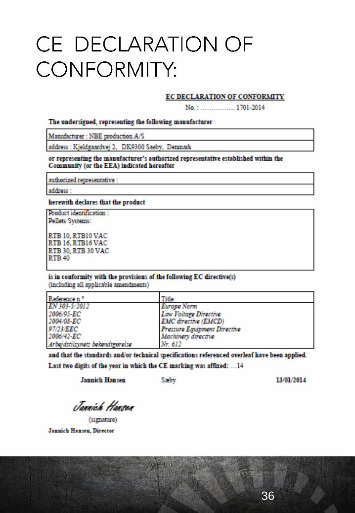
36
37
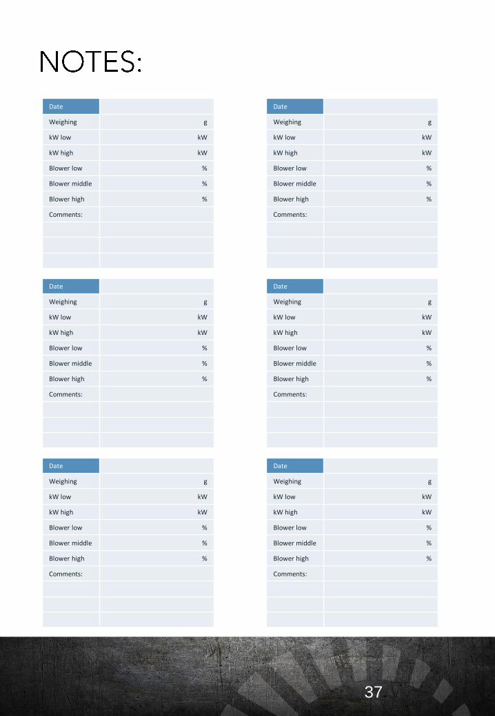
Date
Weighing g
kW low kW
kW high kW
Blower low %
Blower middle %
Blower high %
Comments:
Date
Weighing g
kW low kW
kW high kW
Blower low %
Blower middle %
Blower high %
Comments:
Date
Weighing g
kW low kW
kW high kW
Blower low %
Blower middle %
Blower high %
Comments:
Date
Weighing g
kW low kW
kW high kW
Blower low %
Blower middle %
Blower high %
Comments:
Date
Weighing g
kW low kW
kW high kW
Blower low %
Blower middle %
Blower high %
Comments:
Date
Weighing g
kW low kW
kW high kW
Blower low %
Blower middle %
Blower high %
Comments: