energy storage control in renewable energy based ac...
TRANSCRIPT
International Journal of Innovations in Engineering and Technology (IJIET)
502
Volume 7 Issue 3 October 2016 ISSN: 2319 - 1058
Energy Storage Control in Renewable Energy Based AC Islanded Microgrid
Dandamudi Anilkumar (M.Tech Student EEE Department, Prasad V.Potluri Siddhartha Institute of Technology, A.P, India)
B. Mohan (Assistant Professor, EEE Department, Prasad V.Potluri Siddhartha Institute of Technology, A.P,
India) ABSTRACT: This paper presents a brand new strategy to regulate the generated power from energy sources existing in autonomous and isolated Microgrids (MG). During this specific study, the power system consists of a power convertor supplied by a energy storage system (ESS), that is employed to form the ac grid GFC (grid former converter), associate energy source supported a wind turbine, photovoltaic (PV) generation with its respective Power electronic converter GSC (grid supplier converter), and therefore the power consumers . The main objective of this proposed strategy is to regulate the state of charge of the battery bank ESS, wind turbine (WT), photovoltaic (PV) generation and loads, a coordinated active power regulation is needed to ensure efficient utilization of renewable energy, whereas keeping the ESS from overcharge and over discharge conditions. By limiting the voltage on its terminals by controlling the power generated by the energy sources. This is often done without using dump loads or any physical communication among the power electronic converters or the individual energy source controllers. The electrical frequency of the microgrid is employed to inform the power sources and their respective converters regarding the quantity of power that they need to generate in order to maintain the battery-bank charging voltage below or equal its maximum allowable limit. Experimental results are conferred to indicate the practicability of the proposed control strategy. Key words: Battery banks, power control, renewable energy sources(RES’s), isolated microgrids.
I.INTRODUCTION Around the world, a major number of villages have no access to electricity because of their remoteness.
Fortunately, in many of those places, like in oceanic islands; there are renewable energy sources, significantly solar radiation and wind energies also. These energy resources may be used to form isolated MG’s to fulfill local energy needs [1], [2].
With the objective to electrify remote areas and energy islands, the microgrid conception is gaining
more and more popularity. The MG is recommended by the Consortium or electric reliability Technology Solutions (CERTS) first. The consortium for electric reliability Technology Solutions (CERTS) initiated the analysis on the impact of connecting large amounts of distributed energy resources (DER) to low voltage networks so as to reinforce the reliability of the electric power system and developed the MG conception [1]. Resources like fuel cells, solar PV arrays and wind turbines along with power electronic converters, energy storage devices (i.e. batteries, super capacitors and flywheels) and customer loads, that could be operate independently. MG are often considered as a local grid with multiple distributed generators (DGs), ESS, and loads, ready to operate either in grid connected or islanded mode Microgrids will provide clean, reliable and uninterruptible power. Hence, the coordinated active power management strategy should take under consideration status of all microgrid components such as the SoC of ESS, power offered from the Wind, PV systems by using battery banks, and demand of power consumption. Microgrids need outlined boundary, Industrial customer, campus, substation, match load and generation, voltage, frequency and power factor within tolerances. The applications of MG’s will vary in storage, advanced controls, size in Mega Watts, generation resource sorts, microgrid worth proposition. The MG’s offers Energy security, grid independence capability and ensure energy supply for essential loads utilizing on site generation. MG’s are amongst the major forthcoming entities which not only enable us to achieve this however additionally offer secured high quality power to the loads.
International Journal of Innovations in Engineering and Technology (IJIET)
503
Volume 7 Issue 3 October 2016 ISSN: 2319 - 1058
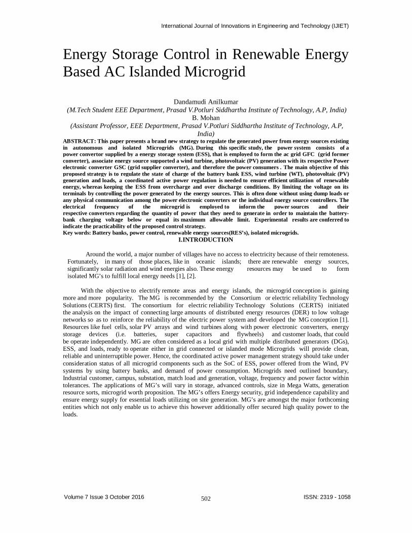
Fig.1. Proposed model for the Microgrid.
MG has two typical operational modes:
Grid- connected mode and islanded mode [6]. Below traditional circumstances, the MG operates in grid-connected mode that is connected to the upstream grid, being either partly equipped from it or injecting some quantity of power into it. However, under emergency circumstances, the MG switches to islanded mode when a fault or link failure happens within the upstream grid, which disconnects from the upstream grid and operates autonomously promptly. Grid Connected mode of operation:
The power Stream MG is connected to the distribution system and is supply energy to the grid using renewable solar or wind power. Keep electricity from the sodium Nickel Chloride, lithium ion Battery and Lead Acid Battery Systems also can be used to provide energy to the grid. Throughout the supply to Grid in operation mode, the gas generator won't be operated. Island mode of operation:
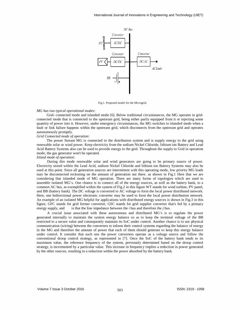
During this mode renewable solar and wind generators are going to be primary source of power. Electricity stored within the Lead Acid, sodium Nickel Chloride and lithium ion Battery Systems may also be used at this point. Since all generation sources are intermittent with this operating mode, low priority MG loads may be disconnected reckoning on the amount of generation out there. as shown in Fig.1 Here that we are considering that islanded mode of MG operation. There are many forms of topologies which are used to assemble isolated MG’s. One chance is to connect all of the energy sources, as well as the battery bank, to a common AC bus, as exemplified within the system of Fig.2 in this figure WT stands for wind turbine, PV panel, and BB (battery bank). The DC voltage is converted to AC voltage to form the local power distributed network. Here, one bidirectional power electronic converter may be used to form the local power distribution network. An example of an isolated MG helpful for applications with distributed energy sources is shown in Fig.3 in this figure, GFC stands for grid former converter, GSC stands for grid supplier converter that's fed by a primary energy supply, and is that the line impedance between the i bus and therefore the j bus.
A crucial issue associated with these autonomous and distributed MG’s is to regulate the power generated internally to maintain the system energy balance so as to keep the terminal voltage of the BB restricted to a secure value and consequently maintain its SoC under control. Another chance is to use physical communication (wiring) between the converters to inform their control systems regarding the balance of energy in the MG and therefore the amount of power that each of them should generate to keep this energy balance under control. It consider that each one the power converters operate as a voltage source and follow the conventional droop control strategy, as represented in [7]. Once the SoC of the battery bank tends to its maximum value, the reference frequency of the system, previously determined based on the droop control strategy, is incremented by a particular value. This increase in frequency implies a reduction in power generated by the other sources, resulting in a reduction within the power absorbed by the battery bank.
International Journal of Innovations in Engineering and Technology (IJIET)
504
Volume 7 Issue 3 October 2016 ISSN: 2319 - 1058
Fig.2. Microgrid example with DG and ac bus.
This paper proposes strategy to regulate the generated power within an isolated ac MG with distributed
RES. The proposal is to regulate the terminal voltage of the existing BB below or equal its maximum allowable value. This is often done by limiting the amount of power that every energy source will generate at every instant, as shown in [3]. The MG frequency is employed to characterize the state of charge of the BB and quantify to the converters’ control systems what proportion power they have or will generate to maintain under control the internal power balance of the MG.
The control of the BB terminal voltage implies indirectly the management of their SoC. The main contributions of this description of the converter controllers and a brand new methodology to control the generated power by the wind turbine, and PV cell by a brand new design and standardization of the terminal voltage controller of the BB, and by the presentation of experimental results, as well as variable wind speed operation and constant wind speed. This microgrid is employed to show the feasibleness of the proposed strategy.
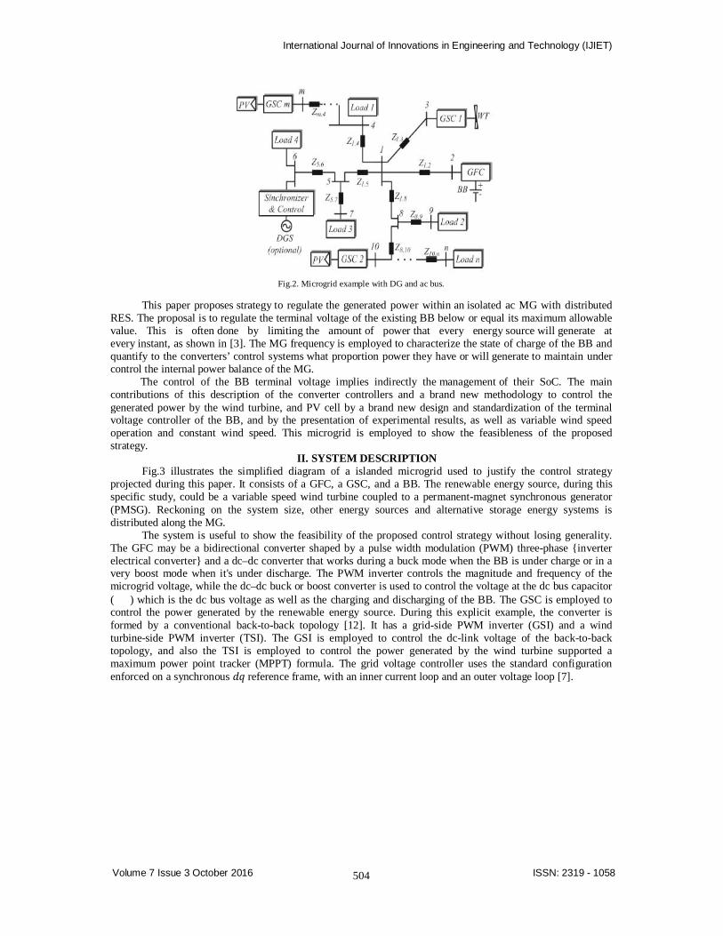
II. SYSTEM DESCRIPTION Fig.3 illustrates the simplified diagram of a islanded microgrid used to justify the control strategy
projected during this paper. It consists of a GFC, a GSC, and a BB. The renewable energy source, during this specific study, could be a variable speed wind turbine coupled to a permanent-magnet synchronous generator (PMSG). Reckoning on the system size, other energy sources and alternative storage energy systems is distributed along the MG.
The system is useful to show the feasibility of the proposed control strategy without losing generality. The GFC may be a bidirectional converter shaped by a pulse width modulation (PWM) three-phase inverter electrical converter and a dc–dc converter that works during a buck mode when the BB is under charge or in a very boost mode when it's under discharge. The PWM inverter controls the magnitude and frequency of the microgrid voltage, while the dc–dc buck or boost converter is used to control the voltage at the dc bus capacitor ( ) which is the dc bus voltage as well as the charging and discharging of the BB. The GSC is employed to control the power generated by the renewable energy source. During this explicit example, the converter is formed by a conventional back-to-back topology [12]. It has a grid-side PWM inverter (GSI) and a wind turbine-side PWM inverter (TSI). The GSI is employed to control the dc-link voltage of the back-to-back topology, and also the TSI is employed to control the power generated by the wind turbine supported a maximum power point tracker (MPPT) formula. The grid voltage controller uses the standard configuration enforced on a synchronous 푑푞 reference frame, with an inner current loop and an outer voltage loop [7].
International Journal of Innovations in Engineering and Technology (IJIET)
505
Volume 7 Issue 3 October 2016 ISSN: 2319 - 1058
Fig.3. Simplified diagram of the studied microgrid.
The frequency and voltage reference values are calculated using droop control strategy as functions of the active and reactive power respectively at the GFC terminals.
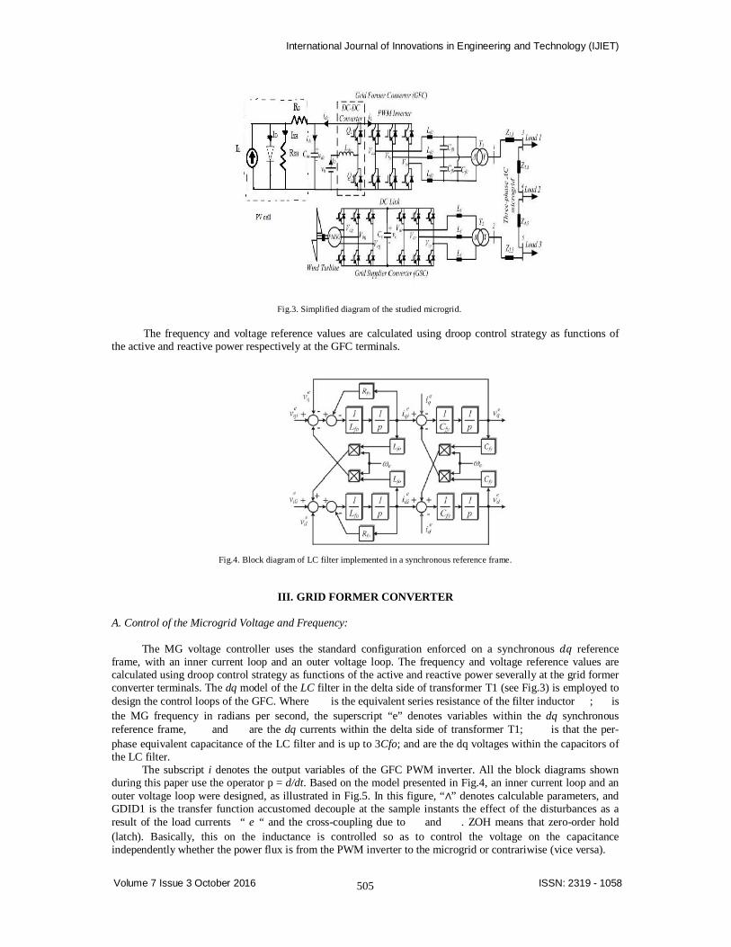
Fig.4. Block diagram of LC filter implemented in a synchronous reference frame.
III. GRID FORMER CONVERTER
A. Control of the Microgrid Voltage and Frequency:
The MG voltage controller uses the standard configuration enforced on a synchronous 푑푞 reference frame, with an inner current loop and an outer voltage loop. The frequency and voltage reference values are calculated using droop control strategy as functions of the active and reactive power severally at the grid former converter terminals. The dq model of the LC filter in the delta side of transformer T1 (see Fig.3) is employed to design the control loops of the GFC. Where is the equivalent series resistance of the filter inductor ; is the MG frequency in radians per second, the superscript “e” denotes variables within the dq synchronous reference frame, and are the dq currents within the delta side of transformer T1; is that the per-phase equivalent capacitance of the LC filter and is up to 3Cfo; and are the dq voltages within the capacitors of the LC filter.
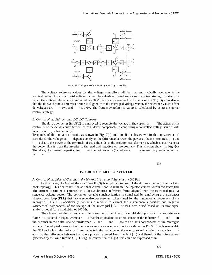
The subscript i denotes the output variables of the GFC PWM inverter. All the block diagrams shown during this paper use the operator p = d/dt. Based on the model presented in Fig.4, an inner current loop and an outer voltage loop were designed, as illustrated in Fig.5. In this figure, “∧” denotes calculable parameters, and GDID1 is the transfer function accustomed decouple at the sample instants the effect of the disturbances as a result of the load currents “ e “ and the cross-coupling due to and . ZOH means that zero-order hold (latch). Basically, this on the inductance is controlled so as to control the voltage on the capacitance independently whether the power flux is from the PWM inverter to the microgrid or contrariwise (vice versa).
International Journal of Innovations in Engineering and Technology (IJIET)
506
Volume 7 Issue 3 October 2016 ISSN: 2319 - 1058
Fig.5. Block diagram of the Microgrid voltage controller.
The voltage reference values for the voltage controllers will be constant, typically adequate to the
nominal value of the microgrid voltage, or will be calculated based on a droop control strategy. During this paper, the voltage reference was mounted in 220 V (rms line voltage within the delta side of T1). By considering that the dq synchronous reference frame is aligned with the microgrid voltage vector, the reference values of the dq voltages are = 0V, and =179.6V. The frequency reference value is calculated by using the power control strategy.
B. Control of the Bidirectional DC–DC Converter
The dc–dc converter (in GFC) is employed to regulate the voltage in the capacitor . The action of the controller of the dc–dc converter will be considered comparable to connecting a controlled voltage source, with mean value , between the xy Terminals of the converter circuit, as shown in Fig. 7(a) and (b). If the losses within the converter aren't considered, the voltage on depends solely on the difference between the power at the BB terminals ( ) and ( ) that is the power at the terminals of the delta side of the isolation transformer T1, which is positive once the power flux is from the inverter to the grid and negative on the contrary. This is often shown in Fig.7(c). Therefore, the dynamic equation for will be written as in (1), wherever is an auxiliary variable defined by =
(1)
IV. GRID SUPPLIER CONVERTER
A. Control of the Injected Current in the Microgrid and the Voltage at the DC Bus In this paper, the GSI of the GSC (see Fig.3) is employed to control the dc bus voltage of the back-to-
back topology. This controller uses an inner current loop to regulate the injected current within the microgrid. The current controller is enforced in a dq synchronous reference frame aligned with the microgrid positive sequence voltage vector. The converter variable synchronization is completed by employing a synchronous phase-locked loop (PLL) that has a second-order resonant filter tuned for the fundamental frequency of the microgrid. This PLL additionally contains a module to extract the instantaneous positive and negative symmetrical components of the voltage of the microgrid [13]. The PLL was tuned based on its tiny signal analysis model for a bandwidth of 100 Hz.
The diagram of the current controller along with the filter ( ) model during a synchronous reference frame is illustrated in Fig.6, wherever is that the equivalent series resistance of the inductor lf , and are the currents in the delta side of transformer T2, and and are the dq axis components of the microgrid voltage. The adopted current direction references are an equivalent as those shown in Fig.3. If the losses within the GSI and within the inductor lf are neglected, the variation of the energy stored within the capacitor is equal to the difference between the active powers received from the MG ( ) and therefore the active power generated by the wind turbine ( ). Using the convention of Fig.3, this could be expressed as in
= . (2)
International Journal of Innovations in Engineering and Technology (IJIET)
507
Volume 7 Issue 3 October 2016 ISSN: 2319 - 1058
For a dq synchronous reference frame aligned with the microgrid voltage vector, it follows that = 0.
Therefore, Ps is adequate to (3/2) , with being the magnitude of the part voltage, thought-about constant in this application. By defining adequate to (3/2 ), the dynamic equation for the capacitor is presented in
= (3)
B. Control of the Wind Turbine Generated Power
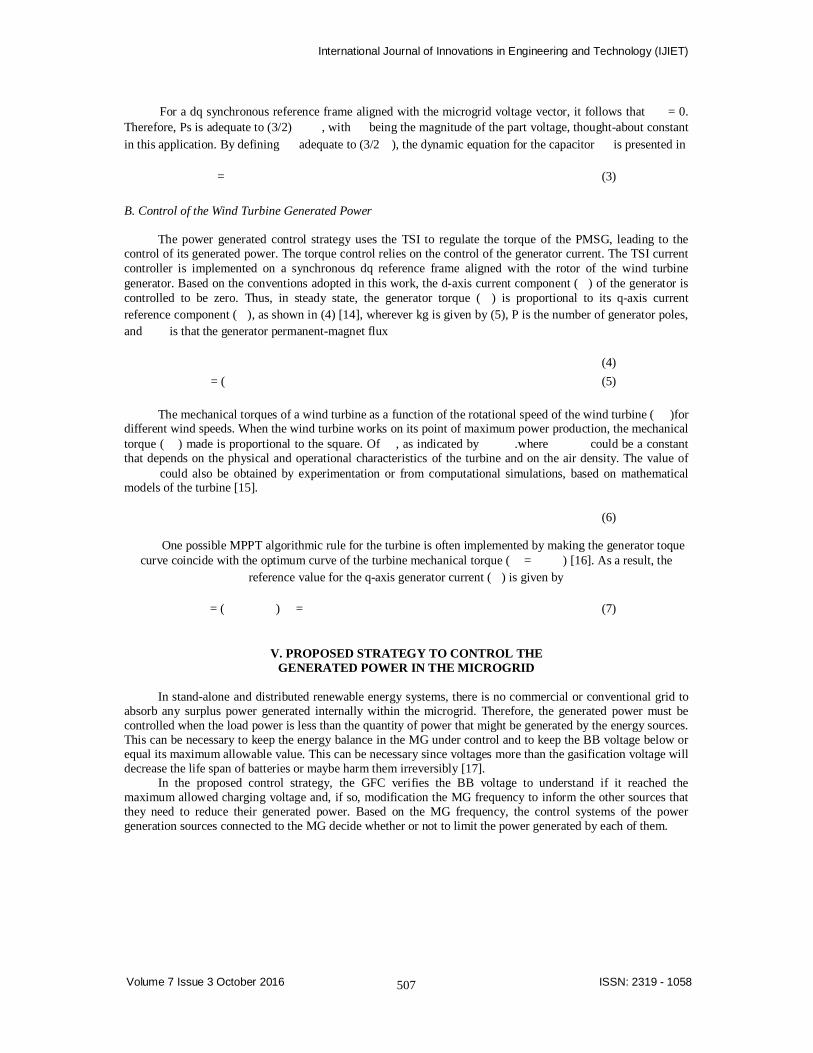
The power generated control strategy uses the TSI to regulate the torque of the PMSG, leading to the control of its generated power. The torque control relies on the control of the generator current. The TSI current controller is implemented on a synchronous dq reference frame aligned with the rotor of the wind turbine generator. Based on the conventions adopted in this work, the d-axis current component ( ) of the generator is controlled to be zero. Thus, in steady state, the generator torque ( ) is proportional to its q-axis current reference component ( ), as shown in (4) [14], wherever kg is given by (5), P is the number of generator poles, and is that the generator permanent-magnet flux
(4)
= ( (5) The mechanical torques of a wind turbine as a function of the rotational speed of the wind turbine ( )for
different wind speeds. When the wind turbine works on its point of maximum power production, the mechanical torque ( ) made is proportional to the square. Of , as indicated by .where could be a constant that depends on the physical and operational characteristics of the turbine and on the air density. The value of
could also be obtained by experimentation or from computational simulations, based on mathematical models of the turbine [15].
(6)
One possible MPPT algorithmic rule for the turbine is often implemented by making the generator toque
curve coincide with the optimum curve of the turbine mechanical torque ( = ) [16]. As a result, the reference value for the q-axis generator current ( ) is given by
= ( ) = (7)
V. PROPOSED STRATEGY TO CONTROL THE GENERATED POWER IN THE MICROGRID
In stand-alone and distributed renewable energy systems, there is no commercial or conventional grid to
absorb any surplus power generated internally within the microgrid. Therefore, the generated power must be controlled when the load power is less than the quantity of power that might be generated by the energy sources. This can be necessary to keep the energy balance in the MG under control and to keep the BB voltage below or equal its maximum allowable value. This can be necessary since voltages more than the gasification voltage will decrease the life span of batteries or maybe harm them irreversibly [17].
In the proposed control strategy, the GFC verifies the BB voltage to understand if it reached the maximum allowed charging voltage and, if so, modification the MG frequency to inform the other sources that they need to reduce their generated power. Based on the MG frequency, the control systems of the power generation sources connected to the MG decide whether or not to limit the power generated by each of them.
International Journal of Innovations in Engineering and Technology (IJIET)
508
Volume 7 Issue 3 October 2016 ISSN: 2319 - 1058
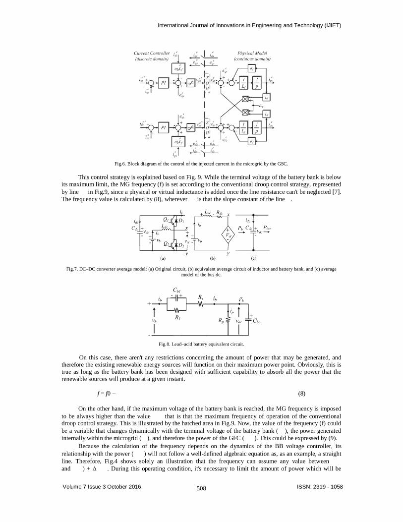
Fig.6. Block diagram of the control of the injected current in the microgrid by the GSC.
This control strategy is explained based on Fig. 9. While the terminal voltage of the battery bank is below
its maximum limit, the MG frequency (f) is set according to the conventional droop control strategy, represented by line in Fig.9, since a physical or virtual inductance is added once the line resistance can't be neglected [7]. The frequency value is calculated by (8), wherever is that the slope constant of the line .
Fig.7. DC–DC converter average model: (a) Original circuit, (b) equivalent average circuit of inductor and battery bank, and (c) average
model of the bus dc.
Fig.8. Lead–acid battery equivalent circuit.
On this case, there aren't any restrictions concerning the amount of power that may be generated, and
therefore the existing renewable energy sources will function on their maximum power point. Obviously, this is true as long as the battery bank has been designed with sufficient capability to absorb all the power that the renewable sources will produce at a given instant.
f = f0 – (8)
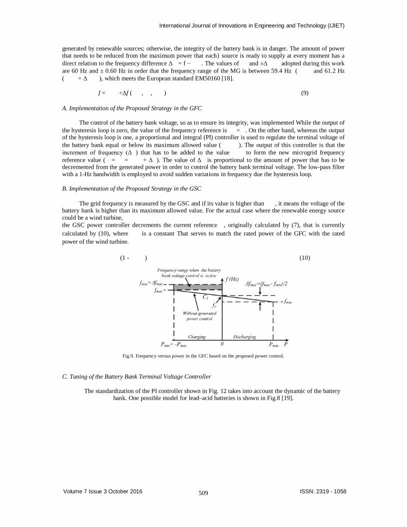
On the other hand, if the maximum voltage of the battery bank is reached, the MG frequency is imposed
to be always higher than the value that is that the maximum frequency of operation of the conventional droop control strategy. This is illustrated by the hatched area in Fig.9. Now, the value of the frequency (f) could be a variable that changes dynamically with the terminal voltage of the battery bank ( ), the power generated internally within the microgrid ( ), and therefore the power of the GFC ( ). This could be expressed by (9).
Because the calculation of the frequency depends on the dynamics of the BB voltage controller, its relationship with the power ( ) will not follow a well-defined algebraic equation as, as an example, a straight line. Therefore, Fig.4 shows solely an illustration that the frequency can assume any value between and ) + Δ . During this operating condition, it's necessary to limit the amount of power which will be
International Journal of Innovations in Engineering and Technology (IJIET)
509
Volume 7 Issue 3 October 2016 ISSN: 2319 - 1058
generated by renewable sources; otherwise, the integrity of the battery bank is in danger. The amount of power that needs to be reduced from the maximum power that each source is ready to supply at every moment has a direct relation to the frequency difference Δ = f − . The values of and ±Δ adopted during this work are 60 Hz and ± 0.60 Hz in order that the frequency range of the MG is between 59.4 Hz ( and 61.2 Hz ( + Δ ), which meets the European standard EM50160 [18].
f = +Δf ( , , ) (9)
A. Implementation of the Proposed Strategy in the GFC
The control of the battery bank voltage, so as to ensure its integrity, was implemented While the output of
the hysteresis loop is zero, the value of the frequency reference is = . On the other hand, whereas the output of the hysteresis loop is one, a proportional and integral (PI) controller is used to regulate the terminal voltage of the battery bank equal or below its maximum allowed value ( ). The output of this controller is that the increment of frequency (Δ ) that has to be added to the value to form the new microgrid frequency reference value ( = = + Δ ). The value of Δ is proportional to the amount of power that has to be decremented from the generated power in order to control the battery bank terminal voltage. The low-pass filter with a 1-Hz bandwidth is employed to avoid sudden variations in frequency due the hysteresis loop.
B. Implementation of the Proposed Strategy in the GSC
The grid frequency is measured by the GSC and if its value is higher than , it means the voltage of the
battery bank is higher than its maximum allowed value. For the actual case where the renewable energy source could be a wind turbine, the GSC power controller decrements the current reference , originally calculated by (7), that is currently calculated by (10), where is a constant That serves to match the rated power of the GFC with the rated power of the wind turbine.
(1 - ) (10)
Fig.9. Frequency versus power in the GFC based on the proposed power control.
C. Tuning of the Battery Bank Terminal Voltage Controller
The standardization of the PI controller shown in Fig. 12 takes into account the dynamic of the battery bank. One possible model for lead–acid batteries is shown in Fig.8 [19].
International Journal of Innovations in Engineering and Technology (IJIET)
510
Volume 7 Issue 3 October 2016 ISSN: 2319 - 1058
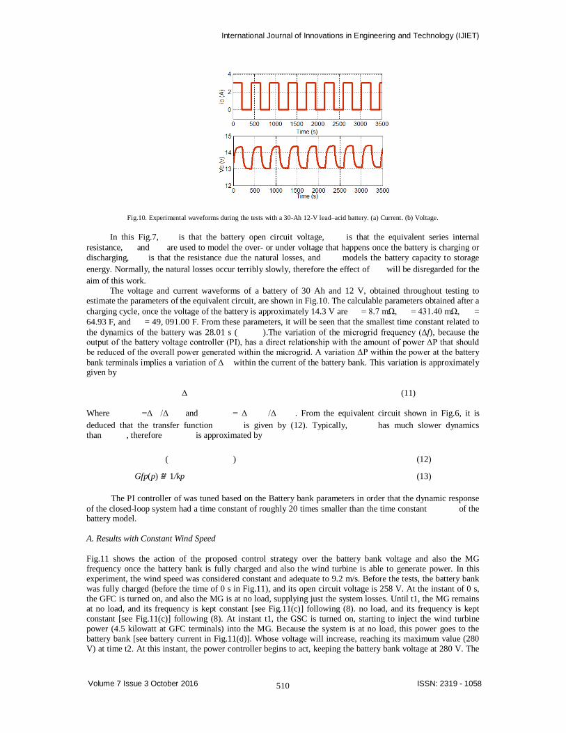
Fig.10. Experimental waveforms during the tests with a 30-Ah 12-V lead–acid battery. (a) Current. (b) Voltage.
In this Fig.7, is that the battery open circuit voltage, is that the equivalent series internal resistance, and are used to model the over- or under voltage that happens once the battery is charging or discharging, is that the resistance due the natural losses, and models the battery capacity to storage energy. Normally, the natural losses occur terribly slowly, therefore the effect of will be disregarded for the aim of this work.
The voltage and current waveforms of a battery of 30 Ah and 12 V, obtained throughout testing to estimate the parameters of the equivalent circuit, are shown in Fig.10. The calculable parameters obtained after a charging cycle, once the voltage of the battery is approximately 14.3 V are = 8.7 mΩ, = 431.40 mΩ, = 64.93 F, and = 49, 091.00 F. From these parameters, it will be seen that the smallest time constant related to the dynamics of the battery was 28.01 s ( ).The variation of the microgrid frequency (Δf), because the output of the battery voltage controller (PI), has a direct relationship with the amount of power ΔP that should be reduced of the overall power generated within the microgrid. A variation ΔP within the power at the battery bank terminals implies a variation of Δ within the current of the battery bank. This variation is approximately given by
Δ (11)
Where =Δ /Δ and = Δ /Δ . From the equivalent circuit shown in Fig.6, it is deduced that the transfer function is given by (12). Typically, has much slower dynamics than , therefore is approximated by
( ) (12)
Gfp(p) ≌ 1/kp (13)
The PI controller of was tuned based on the Battery bank parameters in order that the dynamic response of the closed-loop system had a time constant of roughly 20 times smaller than the time constant of the battery model. A. Results with Constant Wind Speed
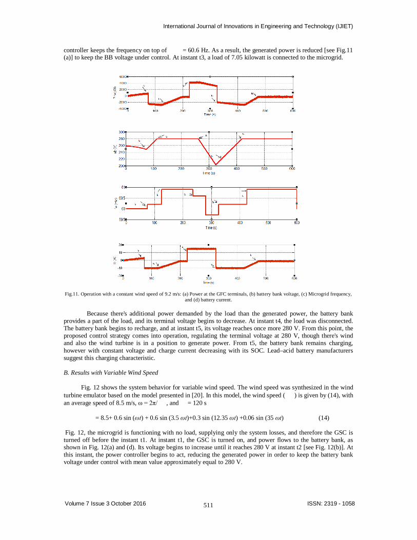
Fig.11 shows the action of the proposed control strategy over the battery bank voltage and also the MG frequency once the battery bank is fully charged and also the wind turbine is able to generate power. In this experiment, the wind speed was considered constant and adequate to 9.2 m/s. Before the tests, the battery bank was fully charged (before the time of 0 s in Fig.11), and its open circuit voltage is 258 V. At the instant of 0 s, the GFC is turned on, and also the MG is at no load, supplying just the system losses. Until t1, the MG remains at no load, and its frequency is kept constant [see Fig.11(c)] following (8). no load, and its frequency is kept constant [see Fig.11(c)] following (8). At instant t1, the GSC is turned on, starting to inject the wind turbine power (4.5 kilowatt at GFC terminals) into the MG. Because the system is at no load, this power goes to the battery bank [see battery current in Fig.11(d)]. Whose voltage will increase, reaching its maximum value (280 V) at time t2. At this instant, the power controller begins to act, keeping the battery bank voltage at 280 V. The
International Journal of Innovations in Engineering and Technology (IJIET)
511
Volume 7 Issue 3 October 2016 ISSN: 2319 - 1058
controller keeps the frequency on top of = 60.6 Hz. As a result, the generated power is reduced [see Fig.11 (a)] to keep the BB voltage under control. At instant t3, a load of 7.05 kilowatt is connected to the microgrid.
Fig.11. Operation with a constant wind speed of 9.2 m/s: (a) Power at the GFC terminals, (b) battery bank voltage, (c) Microgrid frequency,
and (d) battery current.
Because there's additional power demanded by the load than the generated power, the battery bank provides a part of the load, and its terminal voltage begins to decrease. At instant t4, the load was disconnected. The battery bank begins to recharge, and at instant t5, its voltage reaches once more 280 V. From this point, the proposed control strategy comes into operation, regulating the terminal voltage at 280 V, though there's wind and also the wind turbine is in a position to generate power. From t5, the battery bank remains charging, however with constant voltage and charge current decreasing with its SOC. Lead–acid battery manufacturers suggest this charging characteristic. B. Results with Variable Wind Speed
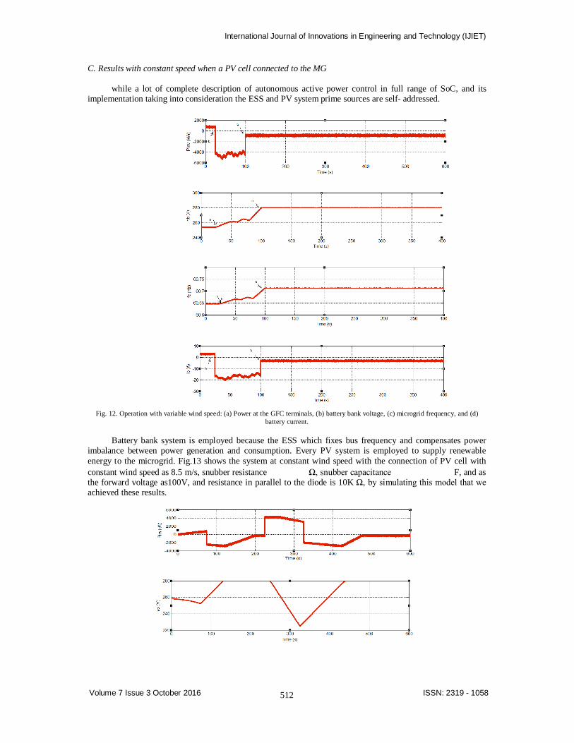
Fig. 12 shows the system behavior for variable wind speed. The wind speed was synthesized in the wind
turbine emulator based on the model presented in [20]. In this model, the wind speed ( ) is given by (14), with an average speed of 8.5 m/s, ω = 2π/ , and = 120 s
= 8.5+ 0.6 sin (ωt) + 0.6 sin (3.5 ωt)+0.3 sin (12.35 ωt) +0.06 sin (35 ωt) (14)
Fig. 12, the microgrid is functioning with no load, supplying only the system losses, and therefore the GSC is turned off before the instant t1. At instant t1, the GSC is turned on, and power flows to the battery bank, as shown in Fig. 12(a) and (d). Its voltage begins to increase until it reaches 280 V at instant t2 [see Fig. 12(b)]. At this instant, the power controller begins to act, reducing the generated power in order to keep the battery bank voltage under control with mean value approximately equal to 280 V.
International Journal of Innovations in Engineering and Technology (IJIET)
512
Volume 7 Issue 3 October 2016 ISSN: 2319 - 1058
C. Results with constant speed when a PV cell connected to the MG
while a lot of complete description of autonomous active power control in full range of SoC, and its implementation taking into consideration the ESS and PV system prime sources are self- addressed.
Fig. 12. Operation with variable wind speed: (a) Power at the GFC terminals, (b) battery bank voltage, (c) microgrid frequency, and (d)
battery current.
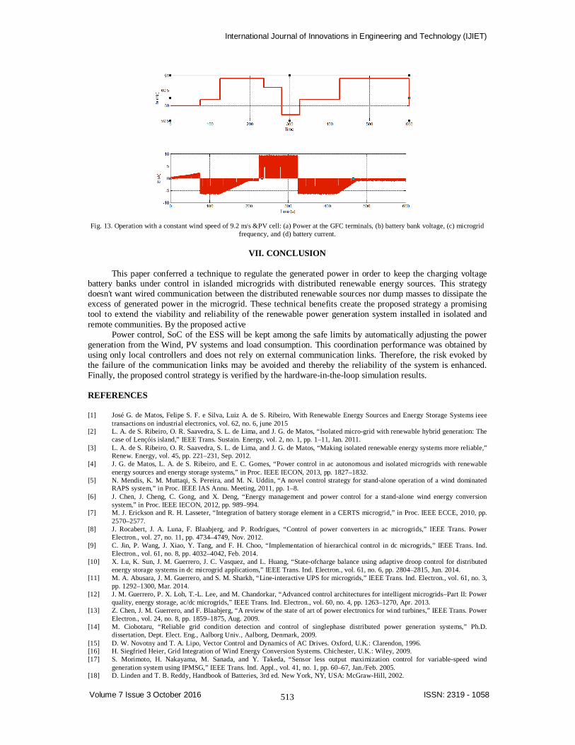
Battery bank system is employed because the ESS which fixes bus frequency and compensates power imbalance between power generation and consumption. Every PV system is employed to supply renewable energy to the microgrid. Fig.13 shows the system at constant wind speed with the connection of PV cell with constant wind speed as 8.5 m/s, snubber resistance Ω, snubber capacitance F, and as the forward voltage as100V, and resistance in parallel to the diode is 10K Ω, by simulating this model that we achieved these results.
International Journal of Innovations in Engineering and Technology (IJIET)
513
Volume 7 Issue 3 October 2016 ISSN: 2319 - 1058
Fig. 13. Operation with a constant wind speed of 9.2 m/s &PV cell: (a) Power at the GFC terminals, (b) battery bank voltage, (c) microgrid
frequency, and (d) battery current.
VII. CONCLUSION
This paper conferred a technique to regulate the generated power in order to keep the charging voltage battery banks under control in islanded microgrids with distributed renewable energy sources. This strategy doesn't want wired communication between the distributed renewable sources nor dump masses to dissipate the excess of generated power in the microgrid. These technical benefits create the proposed strategy a promising tool to extend the viability and reliability of the renewable power generation system installed in isolated and remote communities. By the proposed active
Power control, SoC of the ESS will be kept among the safe limits by automatically adjusting the power generation from the Wind, PV systems and load consumption. This coordination performance was obtained by using only local controllers and does not rely on external communication links. Therefore, the risk evoked by the failure of the communication links may be avoided and thereby the reliability of the system is enhanced. Finally, the proposed control strategy is verified by the hardware-in-the-loop simulation results.
REFERENCES
[1] José G. de Matos, Felipe S. F. e Silva, Luiz A. de S. Ribeiro, With Renewable Energy Sources and Energy Storage Systems ieee
transactions on industrial electronics, vol. 62, no. 6, june 2015 [2] L. A. de S. Ribeiro, O. R. Saavedra, S. L. de Lima, and J. G. de Matos, “Isolated micro-grid with renewable hybrid generation: The
case of Lençóis island,” IEEE Trans. Sustain. Energy, vol. 2, no. 1, pp. 1–11, Jan. 2011. [3] L. A. de S. Ribeiro, O. R. Saavedra, S. L. de Lima, and J. G. de Matos, “Making isolated renewable energy systems more reliable,”
Renew. Energy, vol. 45, pp. 221–231, Sep. 2012. [4] J. G. de Matos, L. A. de S. Ribeiro, and E. C. Gomes, “Power control in ac autonomous and isolated microgrids with renewable
energy sources and energy storage systems,” in Proc. IEEE IECON, 2013, pp. 1827–1832. [5] N. Mendis, K. M. Muttaqi, S. Pereira, and M. N. Uddin, “A novel control strategy for stand-alone operation of a wind dominated
RAPS system,” in Proc. IEEE IAS Annu. Meeting, 2011, pp. 1–8. [6] J. Chen, J. Cheng, C. Gong, and X. Deng, “Energy management and power control for a stand-alone wind energy conversion
system,” in Proc. IEEE IECON, 2012, pp. 989–994. [7] M. J. Erickson and R. H. Lasseter, “Integration of battery storage element in a CERTS microgrid,” in Proc. IEEE ECCE, 2010, pp.
2570–2577. [8] J. Rocabert, J. A. Luna, F. Blaabjerg, and P. Rodrígues, “Control of power converters in ac microgrids,” IEEE Trans. Power
Electron., vol. 27, no. 11, pp. 4734–4749, Nov. 2012. [9] C. Jin, P. Wang, J. Xiao, Y. Tang, and F. H. Choo, “Implementation of hierarchical control in dc microgrids,” IEEE Trans. Ind.
Electron., vol. 61, no. 8, pp. 4032–4042, Feb. 2014. [10] X. Lu, K. Sun, J. M. Guerrero, J. C. Vasquez, and L. Huang, “State-ofcharge balance using adaptive droop control for distributed
energy storage systems in dc microgrid applications,” IEEE Trans. Ind. Electron., vol. 61, no. 6, pp. 2804–2815, Jun. 2014. [11] M. A. Abusara, J. M. Guerrero, and S. M. Sharkh, “Line-interactive UPS for microgrids,” IEEE Trans. Ind. Electron., vol. 61, no. 3,
pp. 1292–1300, Mar. 2014. [12] J. M. Guerrero, P. X. Loh, T.-L. Lee, and M. Chandorkar, “Advanced control architectures for intelligent microgrids–Part II: Power
quality, energy storage, ac/dc microgrids,” IEEE Trans. Ind. Electron., vol. 60, no. 4, pp. 1263–1270, Apr. 2013. [13] Z. Chen, J. M. Guerrero, and F. Blaabjerg, “A review of the state of art of power electronics for wind turbines,” IEEE Trans. Power
Electron., vol. 24, no. 8, pp. 1859–1875, Aug. 2009. [14] M. Ciobotaru, “Reliable grid condition detection and control of singlephase distributed power generation systems,” Ph.D.
dissertation, Dept. Elect. Eng., Aalborg Univ., Aalborg, Denmark, 2009. [15] D. W. Novotny and T. A. Lipo, Vector Control and Dynamics of AC Drives. Oxford, U.K.: Clarendon, 1996. [16] H. Siegfried Heier, Grid Integration of Wind Energy Conversion Systems. Chichester, U.K.: Wiley, 2009. [17] S. Morimoto, H. Nakayama, M. Sanada, and Y. Takeda, “Sensor less output maximization control for variable-speed wind
generation system using IPMSG,” IEEE Trans. Ind. Appl., vol. 41, no. 1, pp. 60–67, Jan./Feb. 2005. [18] D. Linden and T. B. Reddy, Handbook of Batteries, 3rd ed. New York, NY, USA: McGraw-Hill, 2002.

International Journal of Innovations in Engineering and Technology (IJIET)
514
Volume 7 Issue 3 October 2016 ISSN: 2319 - 1058
[19] Voltage Characteristics of Electricity Supplied by Public Electricity Networks, Std. NE 50160, 2010. [20] Z. M. Salameh, M. A. Casacca, andW. A. Lynch, “A mathematical model for lead-acid batteries parallel,” IEEE Trans. Energy
Convers., vol. 7, no. 1, pp. 93–98, Mar. 1992. [21] A. Mirecki, X. Roboam, and F. Richardeau, “Architecture complexity and energy efficiency of small wind turbines,” IEEE Trans.
Ind. Electron., vol. 54, no. 1, pp. 660–670, Feb. 2007.