energy nergys dms reference document …energy northwest pr cti tr verification checklist for...
TRANSCRIPT

,all
ENERGY EC Number-- NERGYS DMS REFERENCE DOCUMENT nfa:-••NORTHWEST D SE u~Peopl,- Vision -Solutions ]INDEX SHEET
aed cal 5.17.19 3Primary Document Identification, , ...... -
D ocum entocu en N u mberS ee D um n
Type Sub-Type Document Number Number Revision
Input References OutputReferencesADD DELETE Type Subtype Doc Number Sheet No ADD DELETE Type Subtype Doc Number Sheet No
I 1T ] PPI PPM OSP-ItHRRIST-Q702
2 " PPI PPM OSP-RHR/IST-Q703
43 E. PPI PPM oSPýRHRAST-Q704
7 " '0 .D[
9o ...[ 0 ... '
I, [T _ [].r
L3 ] Cl C3 " l.' '"
14 1 ]... D [
15 ] O
19 [] 0
............. U][
Note: Note':
~W ~W __ __ ___ _ m.-m __ _
25405 R2

Ezngineezring C22ange
EC :z~t DC2D~ CI1~~~;s/~~~>~ t J7V iI 2
I l l llll I l l I I l lll
E N, E' "YNORTHWEST
__________________________________________________________________________________ - S ~
*- br -t--.1
:-i~,~c*z ~2 UN
~JZ) 9~~i
c-~d'r~'>~: N
~ ~
~r:< r
A Iz:k+%Ai L .
p.Lwi'
M4iles tone Date ?&"mPott namre
7 / ~- ~ ~*7 M
Raq By
Syw t.i
F'acSy DeOaarptziof
Affwcted Ddcumets Z~ist
Sub-Fac Lý~ *P Docu~nont Shoot !ýP :vw 'Fri :n
Cross Aefoez~cos
Rof.
A:,
.-1 ,".
Sub-Numbe rNumber Descriýption
.'.4- ý 1 f.r i:
Engineering Change
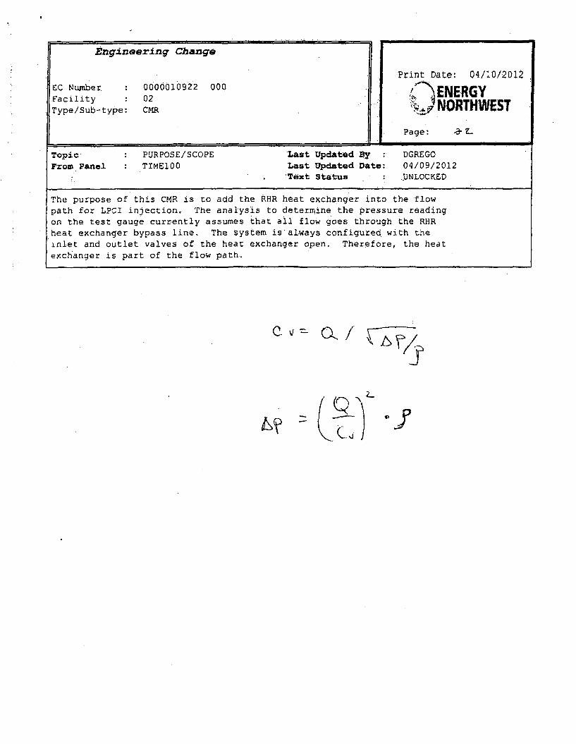
Print Date: 04/10/2012EC Number 0 000010922 000 "GY
Faclit 02ENERGType/Sub-type: CMR NORTHWEST
Page: 3
Topic: PURPOSE/SCOPE Last Updated 5 y DGREGOFrom Panel : TIME100 Last Updated Date: 04/09/2012
'Text Status -_UNLOCKED
The purpose of this CMR is to add the RHR.heat exchanger into the flowpath for LPCI injection. The analysis to determine the pressure readingon the test gauge currently assumes that all flow goes through the RHRheat exchanger bypass line. The system is always configured with theinlet and outlet valves of the heat exchanger open. Therefore, the heatexchanger is part of the flow path.
c~ o.,.j
_KQ- .

Topi.c Last Updated iByFircm Panel F:EiE'Ca Last Updated Date:
Text Status
Talý, vaýUe, Fol-,ho;zld i:m 5511.

Zngr~ineering Change
EC NumberFacilityType/Sub-type:
0000010922 00002CMR
Print Date: 04/10/2012
ENERGY• NORTHWEST
Page:. _- A-
Topic : PREDICTED RESULTS Last Updated By : DGREGOFrom Panel TIME100 Last Updated Date: 04/10/2012
Text Status UNLOCKED
Crediting the RHR heat exchanger flow path in addition to the bypassdecreases flow in. the bypass line from 100% down to 56.25%.. 'Using a moreconservative Cv value for.RHR-V-48A(B) combined with using the parallelflow path of the bypass and heat exchanger results in an increase inmargin of 2.9 psi. It is prudent not to use ail of this marginh therefore-80%, or 2.25 psi will be incorporated into the procedures. Therefore,the acceptance spreadsheets in OSP-RHR/IST-Q702 and .OSP-RHRiIST-Q703 willbe reduced by 2.25 psi.
There are 6 outstanding Modified CMRs against this analysis. This CMRmodifies the results of CMR 10916, 3084 and 93-0588. AR assignmnent00261301 has been created to track incorporation of CMRs either into oneCMR or into the base calculation..

ENERGY NORTHWEST PR Cti tr
VERIFICATION CHECKLIST FORCALCULATIONS AND CMRs
Caltutation/CMVR 10922was ver'fied ujsingo the fo~lowing melthocs:
0 Checklist saiow
Revision 0
E] Aternate Oa-culatom(ws)Checklist Item
Clear statement of pUrpose of analysis .............................................................Methodoloj IS clearly Stated, sufficientfy detailed, and appropriate for the
proposed application ...........................................................................................Is raw data (PDiS) being used as a calculatiorWOMR iitput?
0•Yes No .......................................If yes, ensure the data was 9de0uayvaJlv ated (W1. DES-4-1 step 2.3) .........
Does the analysiSicalculatirn:Methodology (nmciuding criteria and assurr.tions) differ from that 0escrrib int,,.e Pant or ISFSI FSAR or NRC Safety Evaluation Report, or are the resultsof tic ana~ysis/ca!cu!aton as described in the Plrent of ISFSI PSAR or NRCSafety Evaluation Report"M Y e s E N o .................................................. .........................................nvolve a chanqe to an SSC tnat adver-sey affects an FSAR descr-ttd Design
F•nctior o- to an SSC or Cask design thal adverely affacts an ISFSI or CaskFSAR described Destgn Function?nYou M)No .......................................Invoive a cf ange to a procedure Ilat iaversely affects how FSAR describedSSC destgn functions or how ISFSf or Cask FSAR described $SC designfuncrions are perfor ed or controlled?Z Y e s ' 1 N o ...............................................................................................If yes to any of the above questions, ensure that the requirements cf 10 CFR50.59 ar•wdr. I0 CFR 72 48 have he.er processed In accordance wthS W P -L IC -0 2 . ............................................................................................
Does the analysisfceicula; ion result require revising artn• exxs{tirg output interfbcedocument as jdenitfied in DES 4-1, Attachment 7.3?ID Yes [I No ............................................ .f yes, ensu-e that the appropriate actions are taken to revise the outpuinterface document per DES-4-1. Setion 3.1.8. (i.e., document change isinitiated irn accordance with aoilolcable procedures) .........................................
Does the Coulatiofl's Summary of Resaut (or CMR's Predicted Results) Mncludea discussion of avaflabie margin4[l Yes E No 0 Not Applicable.........
Loglcaý conr is ency of at4-n ysiS .............................................................................* Com;rnetefless of documentirng refererces .......................................................* rnom eeIr',ess 0{ irput
* Accuracy Wf .r~ut daa ......................................* Czns.ltency of irp.t ata with approved cr:teria ........................................* Corp!etemess ir. statirp assumpion. ............................
IVa' dC y of assumpto s .......................................• Calcj ation sufficiently detaled ................................................
A rihmnetical accuracy ....................... . ............. I . .........................* Physical ýAnits soecited and correc¢ iy use ..................................................
Reasonableness cf ojtouf conclusion ..............................................................SuperV'sor independency check (If acting as Verifer) ....................................- Did not soe..7y analysis aporoach- Did not n.re iCut specific arafysis o~t~cns* Did n-ot es:abiisn analysis inputs .....................................
V jer Initials
/"
~
.~. ,.

ENERGY NORTHWEST Page Conrd On Page
VERIFICATION CHECKLIST FORCALCULATIONS AND CMRs
Verifier.'InItlalsIf a computer program was used:- Is the program appropriate for the proposed application? .............................. Haventhe program error notices been reviewed to determine if they
pose any limitations for this application? ....... .................- Is the program name, revision number, and date of run inscribed
on the output? ............................. ...... ........Is the program Identified on the Calculation Method Form? ............ . .. .. . .. .. .. ......If so, is it listed in the Software Catalog or if the software Is-used forcalculations completed by vendors Is It done under an approved (10 CFRAppendix B) software program ? ............................ .....................................
If a CMR or calculation revision was prepared against calculation E/I-02-90-01:Verify that manual calculations agree With automatic-calculations on rows withmodified input data ................................................................
- Verify that changesin loading are reflected atithe upstream load centers .- Verify that other calculation cells have been checked as deemed appropriate
by the verifier using manual calculations to assure accuracy has beenm aintained ................................................................................................. .........
. Discussion of Results/Conclusions are: still valid after calculation update. (i.e.,bus & transformer rating not exceeded, etc.) ............................
If the calculation involves an instrument, verify that the calculated values are withinthe instrum ent display range .................... ............ ... ..................................
Other elements considered: Verifier Initials
If separate Verifiers were used for validating these functions or a portion of these functions,
each sign and initial below.
Based on the foregoing, the Calculation/CMR is adequate for the purpose intended.
Verifier Signature(s)/Date Verifier Initials
25280 RIO Page 2 of 2

Pieparod By, D%,i Gregory 'iN"4; CN4R 1P~J2~
Path 1: Branch line around the RHR A" heatexchanger.Note: To be consistent vwith the ba~e calKuIaiorT, W`;Ct MUod'.:fx 'A
ot oý trie deterni rion tlhaLt "A" and q,-' were qimilnr, this CM1'R rymr-ccwt byp~s loop A ,evie~w &vj corndurted to confir- -ha~t the byp~s-c 100P
dferi cnc~s vver ri
P~tt; i; tii 18 1 'ýt-rt at star1 o# rec, end at -.,-.d of teeŽ.
Cal~cu ta~n 5 :71 ists the ;HR pressure n the heat evcŽ-riger as 260 ~vL2.wfnon5..1 7.eC lists Utle krR vs~ur- ',! the hea~t asc 7rnje'~542' s
t'rr*( +~ 1466 (psi' Notp: Th-: rtnu",!; nt the a-lysi% errj insensith/ce to Tre pressure
r *-~ GE Sec 2L- '(1~,14 "Frt!;s Daii"~ fo;r modQ A-1
Pis ir S,ýCUh' d pipe I8"RHW 1)--
p*ýisi ý)avilnu te ý.;ac fl~ rate.
HByvs,. gymA
V 1=
DisI
4 r
Close~ly rnat~cniP FSAFR stait~nem t oFLrypaj.G 101,, -,hra-.jgh izxfht ~ y
X1 6"I -7>(
- ,~'> j
p
~o1c M~4~'\i -k(,- m .-rjr1
fliZirm resistancus, from. C-VI ISO 2,15-00,32S4
Eiriz'Ch tee - VraLx from CtM1F 93K)5& ii --

Prepared By; Dwayne Gregory-t>-- A)e )z.
Verified By: John Feilman (/t i'Il
Piping resistances from CVI ISO 215-00,3037
Pipe := (]Sft + 2.5in) - (2ft + 3in) = 12.958 ft
Pipe:= Pipe-+ [(I 5ft + 7in) - (2ft + 3in) - (2ft + 3in)] =24.042 ft
Pipc := Pipe + I( 13f + 9in) - (2ft + 3in) - (2ft + 3in)- 50inj = 29.125 ft
Pipe := Pipe + [(lOft) - (2ft + 3in) - (2ft + 3in)] = 34.625 ft
Pipe := Pipe + [(lOft + 8in) - (2ft + 3in) - (I 1.25in)] = 42.104 ft
Pipe;= Pipe + 3ft + 2 + L, -0 (11.25in =44.401 ft
CMR 10922
4 lhow.90 := 411. .3-= = 0.797
14.93Cc
Kelbow.45 := ft. 18 '1 = 0,133D18
use 22.37 ft from 93-0588
use 14.93 ft from 93-0588
RFIR-V-48A
CV:= 3511
Used 3.511 to match 93-0588., Vendor confirmed thatthe valves were retested and do not have the Cvfound on the valve drawing.
p Bypass 2.psi = 1.389 psiAvalve' 2 lb CY
ft3
Piping resistances from CVI ISO 215-00,3229
Kec.h := Ktc.b.h + 0.72 = 1.63 from 93-0588 tee branch to run K = 0.72
Determination of dynamic pressure loss in this flow path:
'66PBypuss:= '6ýpvalve + ~~Byass = ~Pa~ve+ 1 ee.b + Kelbow.9O + Kelbow.4s.v = 2,031 psi
x

prepated 13y: Dwayne Ggegofy w'ý6
Voreod BY: Jo6rn FaUmen
Path 2 - Through Heat ExchangerPining reit,ýe ;-om CVI .'SG 215-00,3284
CWMR 109h22
KCjr:= 1r~fx 0,054A Use L for- rur, toe frorn, 93-0i;,88
pjpU~;'- (L.Sft '- 41m, - GMf + 31mn = 21IYsl
L .7fl
Pi jn res~stan~.es f rom CVI IS0 213 5-001,30 7
riptu: Piro *t *,1M ) ý2r ' 1= 8 A3.1 ft
Jlptr.:= PiN~ + +t -11r) - 1 ft 3111; - (2ft + Jilt, -- 3 ý; 5.5 fI
pipe :' Pipe + T1im 1 1" + 2 ii 2n- ýin) - cfl 3iw'= =4Xi.5isfn
Pirw!= fPpc -t -t-[, 6tip) - ( Ift.-f )DI - ln - I .25j ~ =52'$f
ptpc~p:= 60 .5 =
j~,~0.707+ i =1
i),721
'e,> ,' f! l14'

Prepared By: Dwayne Gregory '
Verified By: John Fellman (T m ,': - V// - /,I --
CMR 10922
Kexandr:=2.6.sin(i) ( -l ) 2.291 x. 10 18 inch
End of piping resistances from CVI ISO 215-00,3077
(7450 - Bypass)2
APhx := 8.3psi. -- 1.589psi TEMA sheet states 8.3 .psi, 7450 gpm7e4502
•Piping resistances from CVI ISO 215-00,3228
Pipe2 0 := Pipe20 + [(3ft) - (2O + 6in)) = I ft 20 inch
Pipc2 0 := Pipe. 0 + I (30) - (2ft + 6in)] = 1. ft
For a 20 inch, 90 degree Long Radius ElbowL = LF + LL Reference 7, page 8-1
where L
•LF
LL
= Equivalent Length
= Equivalent Length of Pipe Bend, measured along the axis
= Equivalent Length of Pipe, KLL DLL~ =f
KL = local resistance coefficient
d = Pipe inside diameter
f = Moody diagram friction factor
DB = diameter of pipe bend along axis
Reference 1 - center to face value "A"Rb:= 30.in
d20:= 19in Schedule 30 RHR(.1)-2-2 ASME 11-2
d20
in
f20 := 0.012
inch
crane
2,7, RbLF:= 4

Prepared Ely Dwayne GreZ tr CMF# 10922
A IFoi- 90 cýegrec elbows, per Raleerene 7, p~ 8 2
E mo ~i s For sted1 pipe, Reference 4
0'! F Refenrete 7, Paqe 89-2
dK1 i K1 ! 1
1 20 22"11
11,ilbeW l+ I-L 2 5 . 979 EquwvqVent leycqtr of 20 ricrim Elbow
tu~r M ft ~ to 8 inch
-ir tiujC t + it-2nJ=P.91
Nate: reduccri t; U intch length
P -w. Pitve !'(Wr +- 6in) - (21 3in) - f,20 + 3io) - (Mot) -63.19~3 t
11ifie ~ 1 :. ie- I +ý i - (2 (1 3in - k ~2rv Am 8!,)!

Prepared By: Dwayne Gregory *> "tile •ti-
Verified By: John Feilman ~ ~ '11~CMR 10922
Piping resistances from CVI ISO 215-00,3229
Pipe:= Pipe + [(4ft + 4.5in) - (13.5in)] = 73.109 ft
f, 6.0OftKtcc.r.:= Kice~r + ft. 1 W 6=06f =,.108
D18
End of piping run - now merged back with bypass line
K18 := Ktee.r + Ktec.b + Kuxpander + KrtScducer + Kv,3A + Kv47A + Kelbow.90 + Kelbow.45 2.563
(7450 - Bypass),gpm 4.475 ft
7= 4.475-
(7450 - Bypass).gpm ft
K2 0 :=KeTo200 -3,688-
K2 0 := Klbow2o.q9o 0. 197
AP:= APhx+ p, K.18 + rA. Ppe8 18+D18 )J 2 P,{K 2 0 +Pipý2 0 V20 2
f2 o0 - o - = 2.03 psi
APBypass = 2.031 psi These two values need to match

Pteparea5y. Ow~ayne Gregry.ýq,; GMFI VY-4fý2
verm1ted Bly: Jotvl Fetlmann
Path 3:, Branch, line around the, PHR h~eat, exchanger,no heat exchanger flow
:Tire is zill is ;roi-h start at stam r~ ftc~, end at end of t 'e.
Ulckj .lr /.1 4j lll;is Ltt RHR mrfs-,tur in !%e he,.!*, exd-Tarior z% Z&CD ric,<i.AI zuýat-nn /.40 lists the~ PHR pressutre ir, rric hea* ev-\han', ,jS 2-:4
fý6) ,14,961L P;;3 Note: Tre res-utt of the an~!i aril"2 ~ ~ insensit ve to U1t. Lrpnssre t.m
I t
'Sch~duJl std pipe 213"RHR(11)-2-1
!terato beiow to daermine the bypass flow. Iteration based on bolhpatli havring the same f ow rate.
flypas: 7410 Full fkwv% throuqh bypas.~
-P
stl
if I g o "
I I ! 9 '* o.'ý: 2ý' T ~en from Cra-'e

Prepared By: Dwayne Gregory F_ •G /_CMR 10922
Verified By: John Fellman & Wf•--LffJi--L4
Piping resistances from CVI ISO 215-00,3284
Kt.:0.90 Branch tee - value from CMR 93-0588
Piping resistances from CVI ISO 215,00,3037
Pipe := (15ft + 2-5in) - (2ft + 31n) - 12.958 ft
Pipe := Pipe + [(15ft + 7in) - (2ft +3in) - (2ft + 3in)] = 24.042.ft
Pipe := Pipe + [(I 3ft + 9in) -. (2ft + 3in) - (2ft + 3in).- 50inj = 29.125 ft
Pipe := Pipe + [(loft) - (2ft + 3in) -- (2ft + 3in)] =U4.625 ft
Pipe := Pipe + .[( loft + 8in) - (2f' + 3in) - (I 1.25in)] = 42.104 ft
Pipe: Pi [e+ 3ft + (2+ I in -(I 1.25in) 44,401 ftPipe: Pipe+ L ~ 16j n]4 , 22.37f1
Kelbow.90:= • t.18.- = 0.797 use 22.37 ft from 93-0588Dig= " 14.93f'I
KcIbow.45:= tl.-- 8 = 0.133 use 14.93 ft from 93-0588
RHR-V-48A
Cv:= 3511 changed from 4280 to 3511 to match calc
p (Bypass 2PPvae: ... F... spsi =,4.39 psi
6 2 ,' 4 -\lb
fc3
Piping resistances from CVI ISO 215-00,3229
Ktee.b := t ee.b + 0.72 = 1,63 from 93-0588 tee branch to run K 0.72
Determination of pressure loss in this flow path:
APBypass2 :=APvalve + P"(ft.i18 + Ktee-b + Kelb90 + Klbw4 6A 9psi
D18 5)
APBypass2 - y 4.4 psi Extra margin from crediting paththrough heat exchanger

Prepared By. Owqy'e G pgr CIVIR DQZ22
This CMR ir'~corporaters a coflervatiSm of the CV finr RHIR-V.-48A/B. Tnr- wv,.daw~ing 5tates a Cv of 428CJ irrstead of the 3511 usied nr CMIZ 93-05,.48.,ven'dor bazs confirm, Od that the Cv w-a ratested after the v~ive drawimr, wVZj!issued aid lower Cv values were fot..rd. Therefore, th& vendor cr~duede~that the Cv' is likely 1511 I~s. their 193I1 lette rsti*Lu Instead cf the~ 4*280s-tlown on their draw'rig. UýIirg the Cv value of 3511 aCoos IAS2 psi to tht
-,rr: 4 4 ;X~,% -1,6Ps
? . % - CM46, Pvro ý, 2 - -41, Bypass Fi-aI extra mrgn~rr avoilabke fromzreditirnq the pai&, *,riruuih hF.-i

= P SUVEILANCETEST DISCHARGE PRESSURE CORRECTION TABLES
RHR-P-2A 1 RHR-P-28 RHR-P.2CRequired Required Required
Fkow, gpm I•,e V .9 DlsharVge Discharge.
__________ ii Pressure.;, i. Prossurs', Rsi7490.: j 1265 126 124A57491 12650 !26"59 . 124.39
7492 126:5 5 653 _.24.34
7493 612549 . 4124,287494 - 126:4 , . ,12-4.23
' 7495 . . - , . . -124.177496 12.3 126,26 ::l24•1
7497 125.27 1219 124.067498 128.1 .120:13 124.01.•
7499 1.t 126.06 .123:95
7500 125.10 1 123.907501 T54 125.93 0123.847502 125-99 2 123,787503 1.25:93 "125.79 123.73.704- 12588 125:73 123.57.7505 . . 125;66 23,6
7506 . 125.70 :12- 5.59 0123.56
7507 125.71 125 123507508 '125,656. 125;46 12345
- .7509 ! 125.39 123.397510 1 125:32 123.347511 125:48 125.25 : 123.287512 1 125.19 2 3.227513 ''1 71.2" -123.17-7514 .:125.31 125,05 123.11 "1•7515 . 2124.98 123.067516 125.20 124:91 .123.00
.7517 25:4 2485 ,,2294.
7518 -:15r0 124;78 * 122;'897519 12543 12471.37520 ' '__24 _ ' 122;77
7521 2 124,57 122.727522 124.:86 24,51 . 122567523 i1244 1 22461
.7524 4.37 " 127525 ' 14 1222497526 I 124.23 i 22.44
7527 ' 1 58 124.15 122:387528 t 2 t22:32
7529 12447 124.03 122.27.7530 241 ' . 122.217631 124.35 123•8 122.15
M53 1 123.82 "122.107533 "12424 123;75 _ 2_',04
7534 124,18 123.68 121:98
7535 1"24.3 3 121:927536 1 123.54 124877537 7 123.47 - 121181
7538 12•9 1 121.75
7539 12333 121.70
7540 123.88 123.27 121.Z47541 1217 23.20 121M57542 12.7 125.'13" 115
7543 123.68 123;06 121:,47
7544 123152 '122:99 121:417545 123.56 12. . 21.35754 123.51 122:85 121.307547 1212278 121.7548 12339 122.7121.1

RHo PUMP SURVEILLANCE TST tISCHARGE PRESSURE CORRECTION TA LES
Flvw, 1 sc Dicr 57r~ ihaaPM~rvjru1 . oa{ :pos~rms psi Fi-essw',. cs.
________ 12.64121 127550 i 23. 2. F1 6 l2f, 67
751 123 22 122.5K 121,D'1
715 2&1IC. 12242 Y,20 56.75j123.11 122.36 2,87- 71123.05 . 12 .2 1.2c.84
7555 122:9z. ") 21 2.. 7.1745p, 122.94 '22. 14 120,7?
65"? 122.M. 22. 2C8
7 5 5~ 12zsz 143' J210
1.559 ~ 22, 72' 1.Us 1 201,55
756C 2.P12,5.t3 _____
*16 122.65 1',' 120.437552 122.60 2l' __1____Ow
1 4122,2 12 1. S'- C,__ ____
756___ _ t2 2 -' 1) ,12 6 120 C F
1.1 ' 7,1
.756-9 ~ 2. 23 '22r
2 2.0.9 121.03 11-3857 C7;: 3 7 2 1 0. 11T70
12' 1 .£ -17 " 9,1 .73574_____ 111 8 b 96
Y21.90I 11206 19.56
1z, 761- I ;->F7 i zj-q ? e
77 121.62 120 5- 112,18758 12.1:L7 7204-J _____
7-S,92 141.,45 !.202P 1 917162 lzj;4t 120.21 -1 5 .
;584_____ 121:241 12C. 14 ur -
75$51212.21 120S-V'________ £21.22 120.00 (18 "
7587 .1 131 VS 9.9 189175841 121. 11 M65 11.85/58 1i 15 ,18 _________
75SO7 0. 98 1__IL__7a
75001 1, :4 19,32_
7IW~~6 ~ '8 9 ____1_
120. 1M4
76014 ii,. tit L I
(c3 25_ _ _ _ _ _
_____6 '7 7__ __ _ _ _ -_ _
'-:2 L

7 `1PUMP SURVEILLANCE TEST DISCHARGE PRESSURE CORRECTION TABLES
____ _ RHR-P-2A RHR-P-2B RHR-P,2C* ReqUired Requh:ed Requ red
Flow, gpm Discharge 0ischarge Discharge
P70ssu9 * -,pL Pressur'ei Pressure', psi7609 11!9.90 18,0" 117.61
.76i0 T1T§84 f1•8.23 11.5•
7611 119.79 11816 117A97612 119.73 118.08 1.7613 1 1 1
r"7814 " 1!•1 179 117.31
7615 ' 1!9. 4'.: 117.257518. •1W.50'. 17.19
S 119:44 .17.71 117.13761a • 1•3•. T76 71,•,
7619 '119.32 i 117.56 11,7;017620 119.27 1-7.48 t16"95762.t1192 .117;r'4.1 116.897,62 1.19.15 ' .117;3 11_______
7623 119.09 117.26 116.76
.7624 t119,03 1.17.15 116.707625 118:98 117.11 j 116A34
7628 . 118.92 ' 117.03 116.58
7627 118.88 116.95 118.527•62 118.o 116.88 118.48
7629 118.74 1 116.40
7830 ~1,169 116,73 116.347631 1T16 6 1161287832 ' 1'16.57 .1, .116.22
7633 1161 1 TT6.50 116,17634 1T!4 - 114510
75 '118.'40, 11.35F t, 160476368 118627. 11-.g5.7837 "'.: ' 1 115s927638 118.21 8 57839 1.18.6 '116h0•! 115.797840, ;1 t8:11 i15j9 .11573
7641 118.05 118.89 1.15.67
7642 117"29 1 115.617643 1 - 5,116,:7644 ' 1787 -115.6 115.49
7645 117,81 115.58 11b.4374 117.76 115:50 116.38
:7647 1 1 115.307848 ' 177;6 :!• 1. 1 i.24
.7849 11758. 11.287 57650 11752 115.19 11T'2
Notes:
1. The test acceptance values listed are to be- compared
to the TDAS reading. These acceptance values take into account
that there are flow losses between the pump discharge and the
location of the TDAS instrument and as a result the values listed are
less than actual pump discharge pressures. NOTE: The acceptance
values con'responding to the Tech. Spec. requirements of 7450 gpm
@ 26 psld wetwell to RPV before the correction is factored in are:RHR-P-2A - 131.65 psi, RHR-P-2B - 131.65 psi. RHRP-2C - 128;8
psi.

DIC 413.3A
ENERGY NORTHWESTLICENSING DOCUMENT-CHANGE NOTICE FORM
NUMBER LDCN - FSAR - 10-025 REV. 0 AR 230095BRIEF DESCRIPTION OF ACTIVITY: (3Changing the FPC temperature limit for abnormal operation from 155F to 175F and removing a statement from 9.1.3 that isinconsistent with Table 9.1-6.
REVIEWS AND APPROVALS: Signature indicates authorization to process the subject change into an amendment.
@) POCReview Req'd 0 Yes . No G) POC Meeting No.
CNSRB Review Req'd before submittal C] Yes. No CNSRB Meeting No.
Plant General Manager Approval 0 Yes El No
Ext # 4707Originator Dwayne Gregory Mail Drop PE24 230095-01 Date:
AR Asslgnmnem # or Signature
Originator Supervisor/Manager Jim Brower 230095-09 Date:AR A.algnmoul for Signature
Regulatory ProgramsManagement 230095-10 - Date: _________
AR Assignment # Sg n .tre
0D POC Recommendation for PGM Approval Date:•Signature -
Plant General Manager Approval "__ ___ _ _ _ _ Date: _
Signaure
(2) Activity Initiating the Change @) Forms Attached -. Check all that aoolv-Initiative to support an 18 day outage. 0D AD 10-1432 0 POC Review Criteria
0 Operability Impact Determination Screening/WorksheetRelated or Impacted LBDsLDCN-FSAR-05-005 C] 50.59 Screen _] 7248'Screen
0 50.59 Evaluation 5059-11-003
C] 72.48 Evaluation 7248-
[ Licensing Basis Impact Evaluation LE-
© Hold LDCN Imolementation For Explain:
License Amendment ' ] Yes 0 NoPlant Implementation C] Yes 0 NoOther Change Management E] Yes 0 No
(D Change management actions (include procedure revisions)Action AR Assignment Resp Org/Person
Revise ABN-FPC-LOSS to use 175F instead of 155F.Revise SOP-FPC-START to use 175F instead of 155F.Revise SOP-FPC-DEMIN to use 175F instead of 155F.Revise SOP-FUELPOOL-DRAIN to use 175F instead of 155F.Revise DRD 327 to note that the allowable temperature is 175F, not 155F.
(Tab to insert new row)
24341 R20 Page 1 of 3

NUMBER LDCN - FSAR -10-025 REV. 0 I(Tab to insert new row)
In your review, please ensure:* The reviews required by section 3.1.4 of SWP-LIC-03 have been performed.* The package was reviewed by appropriate subject matter experts, as necessary, to ensure a thorough review.* Comments are attached to the LDCN package or provided electronically via AR assignment.
NOTE: Also include in your review, any forms listed in Section 9 of the LDCN.
(Tab to insert new row)
Date comments providedSection # Reviewer AR assignment # or Signature (May leave blank If tracked by AR)
9.1.3 Steve Kartchner 230095-029.1.3 Tom Morales .230095-039.1.3 Tony Huiatt 230095-04Table 9.1-6 Steve Kartchner 230095-02Table 9.1-6 Tom Morales 230095'03Table 9.1-6 Tony HWiatt 230095-04
I .1-
+ +
I -~
+ +
+ .1-
.1 ~1~ -1-
+ +
+ *1-
+ -4-
(3) Date resolution of commentsComment Resolution provided by AR assignment # or Signature leave ided
Dwayne (May l blank if tracked by AR)Dwayne Gregory if230095-18 i
Acceptance of Comment Resolution Date resolution of commentsand LDCN approval accepted
Reviewer/Approver Name AR assignment # or Signature (May leave blank if tracked by AR)Steve Kartchner 230095-15Tom Morales 230095-16Tony Huiatt 230095-17
24341 R20 Page 2 of 3

NUMBER LDCN - FSAR - 10-025 REV. 0 - AR 230095
CHANGES
LicensingChange Document Brief Description of Each Change Justification for Each Change Change Source Document of Each
No. Section No. Type Change
9.1.3 & Table Changed the temperature limit from 155F back to This change corrects an error that 5059 RS-0019.1-6 the original FSAR value of 175F. changed. the capability value to a limit and EVAL EVAL 5059-11-003
eliminated the real limit. Using the designtemperature.as the limit is acceptable perNRC documents;
2 9.1.3 Removed "normal" from "normal refueling" and The'l 75F limit for a single failure is FA N/Aremoved, "i.e." applicable for normal operation and all
refueling activities with the exception of afull core offload. Full core offload isexcluded since full core off load does notinclude single failure. This is a changerequired to provide consistency betweendifferent sections of the FSAR.
3 9.1.3 Removed the paragraph discussing that the results LDCN-FSAR-05-005 removed the results FA LDCN-FSAR-05-005, pages 13of bounding analysis are included in FSAR Table of bounding analysis from Table 9.1-6. through 15 (changes 259.1-6, as the bounding analysis are no longer Removing this paragraph provides through 42)discussed in Table 9.1-6. consistency between different sections of
the FSAR. The FSAR table Still lists limits, FSAR 9.1.3.3, page 91-31, 2 nd
but there is no need to change this paragraphparagraph from discussing results todiscussing limits since this discussionalready exists in the FSAR.
(Tab to insert new row)
24341 R20 Page 3 of 3

LICENSING DOCUMENT CHANGE NOTICE FORMINSTRUCTIONS FOR COMPLETION OF FORM NO. 24341
NOTE: Refer to SWP-LIC-03 for document specific additional instructions.
ENTRY INFORMATION
1.
2.3.4.
5.
6.7.
8.
9.
10.
11.
12.
13.
Enter the LDCN.and revision number obtained from Regulatory Programs. Listed below are Licensing BasisDocuments and abbreviations to use in LDCN number:TS = Technical Specification 72212 = ISFSI 10 CFR 72.212 EvaluationTSB = Technical Specification Bases OQAPD = Operational Quality Assurance ProgramOL = Operating License Description (50.54a)LCS = Licensee Control Specifications PSP = Physical Security Plan (50.54p)FSAR = Final Safety Analysis Report EP Emergency Plan (50.50q)ODCM = Offsite Dose Calculation Manual COLR = Core Operating Limits ReportIFSAR = ISFSI FSAR
Add AR number as provided by Regulatory Programs.
Provide a brief description of activity.
Determine whether POC,.CNSRB and/or PGM review/approval is required. Complete AR assignment or sign asoriginator.and route.'for Supervisor's/Manager's concurrence for further processing. Supervisor/Manager approvesafter ensurino aoorooriate technical reviews and resolution or comments have been completed.Document POC/CNSRB review (meeting number) if applicable (by POC/CNSRB Coordinator).Regulatory Programs Management ensures all comments are-resolved and approves.The POC Chairman will complete an AR assignment or provide signature recommending PGM approval if required.
Identify the activity that prompted initiation of this LDCN by driving document number. Identify any related orimpacted LBDs byLDCN number or specific section of impacted.LBD.Identify and attach all applicable documents/Forms generated tosupport the LDCN.Answer YES or NO and explain the reason the LDCN should be placed on hold. Examples include: The change isbeing prepared in suooort of a proposed or as a result of a License Amendment or Technical Specification change;another LDCN;.awaiting change management actions such as procedure changes; awaiting plant implementation of adesign change; or, setpoint changes, surveillance requirements or operability requirements.
List any change management actions associated with this change, the AR.# and assignment # created to track theaction and the responsible organization/person responsible for performing the action. Notify procedure group lead(s)or sponsor(s) of required procedure changes.Appropriate reviewers are assigned by originator and confirmed by originator supervision.
NOTE: Technical Reviewers and additional reviewers may be added, or alternative reviewers specified, atmanagement's discretion.
Document resolution of reviewer comments. Approvals of comment resolution via AR assignment completion orsignatures on the LDCN form indicate "approval" of the LDCN package.This field (block 13) may be used to document multiple reviews and/or approval reviewer comments and resolutions.Justification for dissenting comments provided during the LDCN review and approval process (i.e., voiding/revising,etc.) can also be provided in this section.Enter the change number for each change.
Enter the Licensing Document Section/Subsection affected by the change.
Enter a succinct description of each change in the space provided. This will facilitate the review by permitting thereview to focus on the proposed change.
Provide an adequate justification for each change such that a reviewer can understand and evaluate the rationale, forthe change.
Provide the change type as determined on the AD form. If a 50.59 Screen is performed for this item, put SCREEN inthis block. If a 50.59 Evaluation is performed, put EVAL in this block.
Identify specific source documents for existing, new or revised information.
The LDCN review package must contain at least the following:
1) LDCN Form 24341,
2) A copy of any required documents (or links to required files), as noted in Block 9.
3) A copy of marked up LBD pages intended for review.
14.
15.16.
17.
18.
19.
DEFINITION:
24341 R20

COLUMBIA GENERATING STATION Amendment 60FINAL SAFETY ANALYSIS REPORT December 2009
details). The fuel pool is maintained at or below 125°F during normal plant operations. Thefuel pool temperature may rise above this value during refueling activities or during ananticipated operational transient of the loss of one train of the FPC system. The RHR systemcan also be manually aligned into several configurations to provide supplemental cooling of thefuel pool. One of these RHR configurations is the RHR/FPC assist mode of RHR (seeSection 9.1.3.2.2 for additional details).
The maximum heat load is present in the spent fuel pool during refueling activities whenrecently irradiated fuel bundles are discharged from the reactor core ,to the fuel pool. Themagnitude of this heat load is contingent upon the cycle-specific refueling activities, i.e., thenumber of the bundles discharged, the burnup of the discharged bundles, and -the decay time ofeach bundle when it is placed in the fuel pool. The heat load associated with a planneddischarge can be calculated with the ORIGEN-ARP computer code assuming a 2% thermalpower uncertainty or other acceptable means to account for code bias and uncertainties.During refueling activities, the fuel pool temperature is managed by controlling the numberand schedule of fuel assemblies discharged, controlling the number of heat removal systems inservice, and controlling the temperatures of the systems (RCC or SW) used to remove the heatfrom the FPC heat exchangers.
The fuel pool cooling system was originally designed to maintain the pool at a temperature ofless than or equal to 125°F during refueling activities with both trains of fuel pool cooling inoperation and RCC cooling water at 95 *F. The decay heat load assumed for the originaldesign basis (normal offload) was based on the original licensed power of 3323 MW-thermal, aone-year fuel cycle, and a quarter core offload with a 20-day decay period.
Since the original design, the licensed power was increased to 3486 MW-thermal and theoperating cycle was revised from a one-year cycle to a two-year cycle. These changes resultedin an increased heat load in the fuel pool, particularly during refueling outages. For thecurrent design (3486 MW-thermal and a two-year cycle), a 150'F fuel pool temperature limit(see Table 9.1-6) applies to normal refuelpi tivities for the scenario of both trains of fuelpool cooling in operation. O s c a apo snd
TheFPC system is also designed to paovned•afdcent cooling for an anrvcapated operaeionaltransient of the loss of one train of thr system. For adde tois the fhe maximum bulk fuelatvteanter temperature is limited t e 1 F. This limit applies to both normal operation and"oemt~l~(e fueling activitiest(ýxclu ing ia full core offload).
Thsyt ems biit t stifytese temperature limits could be challenged based on outage-specific plans or activities. Outage-specific calculations are performed, as needed, to ensureacceptance criteria limits are maintained and adequate decay heat removal capability exists.Management of the rate and magnitude of the heat load added to the fuel pool during refuelingactivities and the temperature of the credited heat sink (i.e., RCC or SW) are considered.
l
9.1-26

COLUMBIA GENERATING STATION Amendment 60FINAL SAFETY ANALYSIS REPORT December 2009
TTo permit tlhis use of the RHR system, normally locked closed valves interconnecting the RHRT
[system to the FPC system are opened after verification of the installation of the flanged spool|pieces. A full core offload is .a non-routine evolution. A single failure is not .postulated to.
occur during this evolution and credit for RHR/FPC assist is allowed. During this evolution,sufficient cooling should be provided to maintain the fuel pool temperature at less than 145 OF.The licensing basis limit is 175 0F.
The fuel pool heat exchangers are normally cooled by the RCC system to contain releasedSteradioactivity Sse mana in the •event th ulof a polfuel pool waeheat tmeareexchanger elw25tube failure. F DurigOFwenrmoig normalth operations,noia l
Iheat load 'from the fue 1oo.[ Durning normal refueling .outage conditions, .the system is
evaluated to ensure it has e capability to maintain the fuel pool water temperature below150'F. This limit applies to core offloads up to, but not including a full core offload, and isase the of 2 FPC trains in service.. The system maintains fuel pool water
45o the event that only one pump and one heat exchanger areI 7"Favailable. Dependgin•g• Dfthe heat load in the pool during refueling activities, RCC or SW
temperature is controlled to ensure the FPC system can perform its design functions within theacceptance criteria shown in Table 9.1-6.
Following a seismic event or major plant disturbance the SW system is available to cool thefuel pool (by means of FPC or RHR-B heat exchangers) to preclude boiling of the fuel poolwater. The SW pressure is higher than the fuel pool pressure; thus, any leakage will be intothe fuel pool system. In addition, radiation monitors of the SW return line detect any grossfailure in the heat exchangers.
The fuel pool design precludes any condition which could allow the fuel pool to be drainedbelow the pool gate between the reactor well and the fuel pool. Two diffusers are placed inboth the reactor well and the fuel pool to distribute cooled return water efficiently. Diffusersare placed to minimize stratification of either temperature or contamination. Valving isprovided to prevent water from being siphoned out of the pool. [ All1 piping connected to thefuel pool and reactor well, except for drains and liner drains, are Seismic Category 1, including
any normally closed manual or normally open automatic valves that provide isolation from theSeismic Category II portion of the system. Drain and liner drain piping connected to the fuelpool, reactor well, and dryer separator pool are Seismic Category 11 supported to SeismicCategory I requirement~s. s~ifnc~e -te fuel pool system is at low temperature and pressure(moderate energy system) postulated breaks in the Seismic Category I portion are limited to
cracks.
Fuel pool cooling can be established and monitored from the control room following a designbasis LOCA. I ne of the two FPC trains is adequate to prevent fuel pool boiling by a largemargin. I However, during normal plant operation, one or both trains operate to maintain125°F pool water. Should one of the tp4b unavajL1ethe second train operates tomaintain pool water temperature below4 • __• -55 alue is applicable for an

COLUMBIA GENERATING STATION Amendment 60FINAL SAFETY ANALYSIS REPORT December 2009
anticipated operational transient involving the loss of one FPC loop. If the fuel pool heat load
is such that the -resulting temperature transient exceeds 125 IF, procedural guidance :is in placeto restore the fuel. pool temperature to < 125TF. Due to the large thermal capacity of the fuelpool sufficient -operator time is available for the operator to take necessary corrective action tosupplement cooling.
The results of bo g fuel pool c anlses are ded in Table! 9 .These
A makeup water valve controlled by skimmer surge tank level switches supplies water from thecondensate transfer system to the fuel pool•.to replace losses. I The backup source of makeup"I
• at'--• s fo---m h: eimcatg--"-"-' I ysfe- class-' 3 SW syst'e'-'m. This source .supplies makeup"
for. long-term pool water losses.
Each. filter demineralizer is capable of continuous operation at a normal fuel pool water flowrate of 575. gpm or a maximum fuel pool water flow rate of 1000 gpm and will maintain waterconditions as specified in Section 9.1.3.2.
A radiological evaluation of the cleanup system is presented in Chapter 12.
From the foregoing analysis, it is concluded that the FPC system meets its design basis andsatisfies -the requirements of Regulatory Guide 1.13, Revision 1.
9.1.3.4 Testing and Inspection Requirements
Special testing is not required for the system except as noted below because, when fuel isstored in the pool, at least one pump, heat exchanger, and filter demineralizer are routinely inoperation.
Routine, periodic visual inspection of system components, instrumentation, and alarms areadequate to verify system operability. Likewise, the interconnecting valves between the FPCsystem and the RCC, SW, and RHR systems are periodically inspected to verify theiroperability.
9.1.4 FUEL HANDLING SYSTEM
9.1.4.1 Design Bases
The fuel handling system is designed to provide a safe and effective means for transporting andhandling fuel from the time it reaches the plant until it leaves the plant after postirradiationcooling. Safe handling of fuel includes design considerations for maintaining occupationalradiation exposures as low as reasonably achievable during transportation and handling.
9.1-32

Table 9.1-6
Bounding Fuel Pool Cooling Events
RHR Loops in FPCFPC Loops Assist Mode
Fuel Cycle Acceptance CriteriaaLength (OF)
Fuel Pool Heat Load/Scenario (Months) Available Credited Available Credited
Normal refueling (non-transientcondition)
Normal refuelingc (anticipatedoperational transient condition)
24
24
2
1
2
1
1
1
0 150
07~/ 4 JLI n'
W-
Full core offload refuelingd 24 2 0. 1 1 145/175
Normal Operationse (non- 24 2 2 0 0 125transient/non-accident condition)
Normal Operationsf (anticipatedoperational transient condition)
24 1 1 0 0 -i4 - I IS T,F I-
Normal Operationsg (design 24 2 1 0 0 125 (pre-accident)basis LOCA condition) 175 (ýpost-accident)
C)0,0
0

Table 9.1-6
Bounding Fuel Pool Cooling Events (Continued)Performance Data
Table Notes:
a Outage-specific/Cycle-specific calculations are performed, as needed, to ensure acceptance criteria limits are maintained.
b A normal refueling does not involve a full core offload. The normal refueling temperature limits go into effect upon placing the "Ti,.
plant in cold shutdown and remain in effect until plant start-up. The 150°F acceptance criterion is applicable for the case of both >FPC loops available. ,m-
c A normal refueling does not involve a full core offload. 4,Pf ceptance criterion is applicable for an anticipated
operational transient of the loss of one FPC loop.
d A full core offload is a non-routine evolution. Although no single failure is postulated to occur during this evolution, only credit '
for RHR/FPC assist is taken. During this evolution, sufficient cooling is provided to maintain the fuel pool temperature at less 0than 145°F. The licensing basis limit is 175°F. W
e Normal Operations is defined as any plant condition other than a refueling outage. -The normal operation temperature limits V 0
become applicable upon plant start-up following a refueling outage. The 125°F value supports the initial (i.e., preýaccident) fuel
pool temperature assumption in the design basis LOCA analysis.
f Normal Operations is defined as any plant condition other than a refueling outage. Th 155Fe ue is applicable for ananticipated operational transient involving the loss of one FPC loop. If the fuel pool heat load is such that the resultingtemperature transient exceeds 125 0F, procedural guidance is in place to restore the fuel pool temperature to < 125 0F.
>
g Normal Operations is defined as any plant condition other than a refueling outage. The 125°F and 175 0F values support the °°D CSinitial fuel pool temperature assumption and the calculated peak fuel pool temperatures, respectively, in the design basis LOCAanalysis. For this event, RCC is assumed to be lost and SW is manually aligned to the FPC system heat exchangers. Anequilibrium temperature of 90'F is assumed for the SW. a%

Implementing Activity:
Refer to SWP-IRP-01 ENERGY NORTHWEST LDCN-FSAR-10-025POC REVIEW CRITERIA
NOT•: The following questions help determine If the proposed activity is required to be approved by POC. prior toperforming the activity. A YES answer to any of the following questions requires POC reView/approval of the proposedactivity.
C3 Yes [ No Could the proposed activity adversely affect reactivity? (Reactivity is affected by such items as RCStemperature, Main Steam flow, Main Steam :pressure, RRC Pump speed, 'Nuclear Instrumentation,Rod Control System, Fuel, and Fuel Components.)
-l Yes [ No Could the proposed activity result in a significant Plant transient?
Q Yes " No Could the proposed activity feedback into control circuits important to stable Plant operation (e.g.,Feedwater Control, Control Rods)?
C3 Yes 0 No Could the proposed activity result in a malfunction which could feedback into a system :relied upon for.stable Plant operations?
17 Yes [ No Could the proposed activity substantially reduce the ability of Operators to control or monitor the Plant?
ED Yes Z No Does the proposed activity involve the addition or deletion of any temporary loads on a Class 1 Eelectrical distribution system?
E] Yes Z No Is the proposed activity a high risk evolution which could affect nuclear safety?
[ Yes [] No Does the proposed activity require a 10 CFR 50.59 or 10 CFR 72.48 Evaluation?
ED Yes Z No Does the proposed activity change the. Plant or ISFSI Technical Specifications or Operating License?
17 Yes [ No Does the proposed activity change the Licensee Controlled Specifications (LCS)?
El Yes 19 .:No Does the proposed activity change the Offsite Dose Calculation Manual (ODCM)?
M Yes [ No Does the proposed activity change the Process Control Program? (SWP-RMP-01 & SWP-RMP-02)
EJ Yes -:No- Does the -proposed activity change the Security Plan?
Ml Yes . No Does. the proposed.activity change the EmergencyPlan? "
El Yes Z No Does the proposed activity change the Core Operating Limits Report: (COLR)?
EYes [No Does the proposed activity affect the Refueling Outage Shutdown Safety Plan?
El Yes .Z No Could the proposed activity result in a Planned Special Exposure? (GEN-RPP-08)
[3 Yes Z No Could the proposed activity result in a configuration specific Incremental Core Damage Frequency_ _ DF) GT 1 E-31yr, or ORAM-Sentinel Plant Risk Level RED?
E" Yes Z No Does the proposed activity affect post maintenance operability testing for safety-related components?(Revisions to established surveillance procedures do not generally require POC review unless theymeet one of the other review criteria.)
Ml Yes [ No Could the proposed activity cause an uncontrolled draining of the RPV cavity/vessel?
El Yes Z No Does the proposed activity involve a new procedure that defines a regulatory-based program?
El Yes [ No Does the proposed activity involve a procedure change that adds, deletes, or otherwise alters POCreview/approval requirements?
El Yes Z No Does the proposed activity involve a procedure change that includes a substantial change tofundamental station practices (i.e., Work Management Process, Reactivity Management, PERProcess, etc.) or substantial revision to a regulatory-based program?
E] Yes [ No Is the proposed activity a new (Revision 0) Engineering Test procedure revision (Volume 8)?NOTE: Cancelations/deactivations do not require POC review/approval,
Ml Yes [ No Is the proposed activity an Infrequently Performed Test procedure revision (Volume 18)?NOTE.: Cancelationsldeactivations do not require POC review/approval..
Prepared By: Dwayne Gregory 2/22/2011Print Name *gnat Date
26232 R6

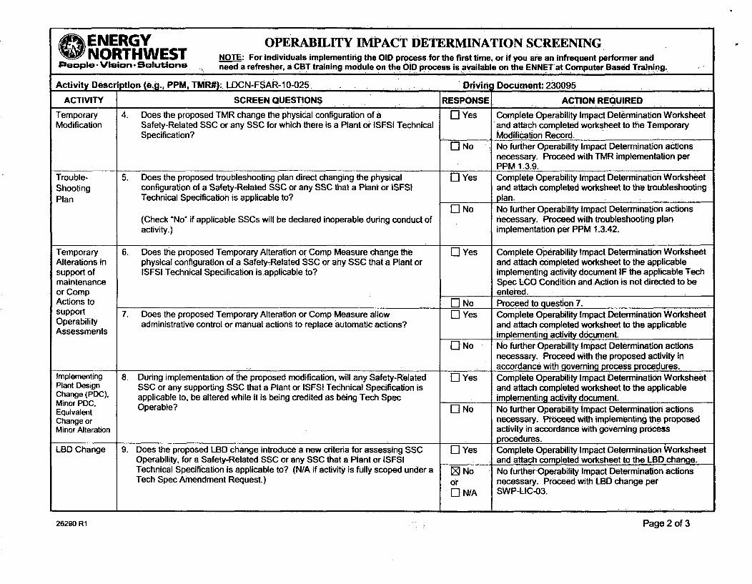
ENERGY OPERABILITY IMPACT DETERMINATION SCREENINGNORTHWEST NOTE: For individuals implementing the OlD process for the first time, or if you are an Infrequent performer and
People. Vision. Solutions ie-ed a refresher, a CBT training module on the OlD process is available on the ENNET at Computer Based Training.
Activity Description (e.g., PPM, TMR#): LDCN-FSAR-10-025 Driving Document: 230095
Performed By: Dwayne Gregory ritae4 Date: 12/2/2010Print Name SigP ,ur . ..
ACTIVITY SCREEN QUESTIONS IRESPONtt ACTION REQUIREDProcedureRevision/Change
1 Does the change to this procedure direct or allow a change in the physicalconfiguration of a Safety-Related SSC or any SSC that is applicable to aPlant or ISFSI Technical Specification (including SSCs that support TechSpec SSC operability)?
L-I Yes Proceed to question la.* -
El No Proceed to question 2.
la. Does the change to this procedure direct or allow this change during an [] Yes Proceed to question lb.operational condition (mode) in which the SSC is required to be Operable? El No Proceed to question 2.
lb. Does the change to this procedure direct entry into the applicable Tech Spec E] Yes Proceed to question 2.LCO Condition and Action? -I No Complete Operability Impact Determination Worksheet
(Form No. 26294) and attach completed worksheet toprocedure revision/change.
2. Does the change to this procedure direct a Safety-Related component I] Yes Proceed to question 2a.configuration change from that set forth in the applicable System Operating I] No Proceed to question 3.Procedures (normal or abnormal) or specified in a design requirementsdocument?
2a. Does the change to this procedure direct or allow this change during an I] Yes Proceed to question 2b.operational condition (mode) in which the SSC is required to be Operable? I] No Proceed to question 3.
2b. Does the change to this procedure direct entry into the applicable Tech Spec E] Yes Proceed to question 3.LCO Condition and Action? [I No Complete Operability Impact Determination Worksheet
and attach completed worksheet to procedure revision.3. Does the change to this procedure allow administrative control or manual [] Yes Proceed to question 3a.
actions to replace automatic functions performed by a Safety-Related SSC? [] No No further Operability Impact Determination actionsnecessary. Proceed with process change perSWP-PROR02.
3a. Does the change to this procedure direct or allow this change during an [] Yes Proceed-to question 3b.operational condition (mode) in which the SSC is required to be Operable? " ] No No further Operability Impact Determination actions
necessary. Proceed with process change perSWP-PRO-02.
3b. Does the change to this procedure direct entry into the applicable Tech SpecLCO Condition and Action?
0l Yes No further Operability Impact Determination actionsnecessary. Proceed with process change perSWP-PRO-02.
El No Complete Operability Impact Determination Worksheetand attach completed worksheet to procedure revision.
26290 R1 Page 1 of 3
ENERGY OPERABILITY IMPACT DETERMINATION SCREENINGNORTHWEST NOTE: For individuals implementing the OlD process for the first time, or if you are an infrequent performer andPeople- Vision- SOluions. need a refresher, a CBT training module on the OlD process is available on the ENNET at Computer Based Training.
Activity Description (e~g., PPM, TMR#): LDCN-FSAR-10-025. Drivini Document: 230095
ACTIVITY SCREEN QUESTIONS RESPONSE. ACTION REQUIRED
Temporary 4. Does the proposed TMR change the physical configuration of a El Yes Complete Operability Impact Determination WorksheetModification Safety-Related SSC or any SSC for which there is a Plant or ISFSI Technical and attach completed worksheet to the Temporary
Specification? Modification Record.El No No further Operability Impact Determination actions
necessary. Proceed with TMR implementation perPPM 1.3.9.
Trouble- 5. Does the proposed troubleshooting plan direct changing the physical El Yes Complete Operability Impact Determination WorksheetShooting configuration of a Safety-Related SSC or any SSC that a Plant or ISFSI and attach completed worksheet to the troubleshootingPlan Technical Specification is applicable to? plan.
El No No further Operability Impact Determination actions(Check "No" if applicable SSCs will be declared inoperable during conduct of necessary. Proceed with troubleshooting planactivity.) implementation per PPM 1.3.42.
Temporary 6. Does the proposed Temporary Alteration or Comp Measure change the E] Yes Complete Operability Impact Determination WorksheetAlterations in physical configuration of a Safety-Related SSC or any SSC that a Plant or and attach completed worksheet to the applicablesupport of ISFSI Technical Specification is applicable to? implementing activity document IF the applicable Techmaintenance Spec LCO Condition and Action is not directed to beor Comp entered.Actions to El No Proceed to question 7.support 7. Does the proposed Temporary Alteration or Comp Measure allow El Yes Complete Operability Impact Determination WorksheetOperability administrative control or manual actions to replace automatic actions? and attach completed worksheet to the applicableAssessments implementing activity document.
EI No No further Operability Impact Determination actionsnecessary. Proceed With the proposed activity inaccordance with goveming process procedures.
Implementing 8. During implementation of the proposed modification, will any Safety-Related El Yes Complete Operability Impact Determination WorksheetPlant Design SSC or any supporting SSC that a Plant or ISFSI Technical Specification is and attach completed worksheet to the applicableChange (PDC), applicable to, be altered while it is being credited as being Tech Spec implementing activity document.Minor PDC, Operable? El No No further Operability impact Determination actionsEquivalentChange or necessary. Proceed with implementing the proposedMinor Alteration activity in accordance With governing process
procedures.LBD Change 9. Does the proposed LBD change introduce a new criteria for assessing SSC El Yes Complete Operability Impact Determination Worksheet
Operability, for a Safety-Related SSC or any SSC that a Plant or ISFSI and attach completed worksheet to the LBD change.Technical Specification is applicable to? (N/A if activity is fully scoped under a ED No No further Operability Impact Determination actionsTech Spec Amendment Request.) or necessary. Proceed with LBD change per
El N/A SWP-LIC-03.
2690R Pg 2.of-
26290 R1 Page 2 of 3

O ENERGY OPERABILITY IMPACT DETERMINATION SCREENINGNORTHWEST NOTE: For individuals implementing the OlD process for the first time, or if you are an infrequent performer andPeople. Vision- Solutions need a refresher, a tCBT training module on.the O!D)process is available on the ENNET at Computer'Based Training.
Activity Description (e.g., PPM, TMR#): LDCN-FSAR-10-025 Driving Document: 230095
Justification for not requiring completion of the Operability Impact Determination Worksheet (provide brief explanation as to why the applicable screeningquestions were checked "No"):
The LBD change does not introduce a new criteria. The LBD increases the allowable temperature for the fuel pool during a loss of one division of cooling from155F to the design temperature of 175F, consistent with the guidance provided in RS-01. This change does not impact the criteria for assessing Operability,which is the capability to preclude fuel pool boiling.
26290 R1 Page 3 of 3

Page:lot ~ e,. ~Control No.Page: I of 2 ENERGY and Implementing Document Number(s) I Rev.
SNORTHWEST Ao-10-1432 Rev: 0People Vision • Solutions AR 230095
APPLICABILITY DETERMINATION FOR LDCN-FSAR-10-025LICENSE ,BASIS CHANGES
CAUTION: Qualification (LDAA or LDAB) is required to:Use This FormPrepared By (Print) Prepared By (Signatlre) DateGREGORY, DE 7:> 03109111 15:39
Reviewed By :(Print) Reviewed Bt (Signaturer De
MORALES, TP a ,_ ---.. 03110111 08:39
I. Brief Description Of Activity: (What Is being changed and why)What:
1. The spent fuel pool temperature limit in FSAR Section 9.1.3,and FSAR Table 9.1-6 Is being revised from 155F to175F.2. The statement that the results of bounding fuel pool cooling analyses are provided in Table 9.1-6 is beingremoved from section 9.1.3.3 of the FSAR.Why:
1. Columbia is currently limited to approximately 30 day or-longer outages because of fuel pool cooling limitations.The increase in allowable temperature from 155F to 175F will permit shorter outages to be performed.2. LDCN-FSAR-05-005 removed the results of bounding analyses from Table 9.1-6; therefore, this statement is nolonger valid.Regulatory Applicability Determination: See the 10 CFR 50.59 Resource Manual (RM), Section 4.2 and/or NEI.96-07, Appendix B, Section B4.1for additional guidance to determine if 10 CFR 50.59 and/or 10CFR 72.48 applies tothe activity. See the reference procedure for guidance todetermine if the activityoaffects the program plan, procedure or manual identified below.
Address eachaspect of the activity. If the answer is YES to any portion ofthe activity, apply the identified process(es) to that portion oftheactivity. Note that it is not unusual to have more than one process apply to a given activity.
II. Regulatory Requirements and Controls (RR): Section 4.2.1 Of the RMDoes the proposed activity Inpact the: Section 4.2.1__ fthe ___
1. Technical Specifications, Operating License or Cask CoC (10 CFR 50.90) [Z]No []EYes if Yes, process per SWP-LIC-03
2. Operational Quality Assurance Program Description (10 CFR 50.54(a)) _'ZNo EYes If Yes, process per SWP-LIC-03
3. Physical Security Plan or Security Training and Qualification Plan (10 CFR.50.54(p)) *(]No EYes If Yes, process per SWP-LIC403
4. Emergency Plan (10 CFR 50.54(q)) 'ZNo [JYes If Yes, process perSWP-LIC-03
5. IST ProgramPlan ( 10 CFR50.55a(f)) .[]No E]Yes If Yes, process.per SWP-IST-01
6. ISIProgram Plan (10.CFR 50.55a(g)) [D No E]•Yes If Yes, process per swP-ISI-01
7. PCLRT Program Plan (Tech. Spec55.12) R'No 0-Yes If Yes, process per PPM 1.5.5
8. Other Programs f] No E]Yes if Yes, process per SWP-LIC-03Examples are: Fire Protection Program, Environmental Plan, ODCM, COLR or other applicable controlling
procedureIll. Maintenance Activities (MA) (Does Not Apply to the ISFSI) Section 4.2.2 of the RM
Does the proposed activity involve:
1. Maintenance which restores SSCs to their original or new approved design condition? Z]No [EYes if Yes, process per SWP-MAI-01or other applicable controllingprocedure
2. A temporary alteration supporting maintenance during an outage or that will be in effect ZNo E]Yes if Yes, process per controllingduring at-power operations for 90 days or less? procedure: e.g, PPM 1.3.9, PPM
10.2.53, GEN-RPP-14IV. FSAR Modifications (FA) Section 4.2.3 of the RM
Does the proposed activity Involve a change to the:
1. FSAR (including documents incorporated by reference ) that is excluded from requirements 1E No I0jYes if Yes, process per SWP-LIC-03to perform a 50.59 or 72.48 review as identified in section 4.2.3 of the Resource Manual.
V. Procedure Governing the Conduct of Operations (AC) Section 4.2.4 of the RMDoes the proposed activity Involves: S 4 f
1. Managerial or administrative procedures or process governing the conduct of facility ZNo []Yes if Yes, process per SWP-PRO-02operations subject to the control of 10 CFR 50, Appendix B. or other applicable controlling
_:; i.. _ procedure2. Regulatory commitment not covered by another regulation based change process. r] No E]Yes if Yes, process per SWP-LIC-01
VI. Environmental Impact Evaluation (EE)Does the proposed activity:
1. Affect the environment, or alter non-radiological plant effluents or rated power level? w]No EYes If Yes, process a License Basis(See SWP-LIC-02) Impact Evaation in accordance
VII. Administrative Activities (AA) Section 4.2.6 of the RMDoes the proposed activity involve a:
1. A change that is an administrative activity subject to the controls of 10 CFR 50, Appendix B. _]No E]Yes If Yes, process per SWP-PRO-02(See SWP-LIC-03, Attachment 7.8) or other applicable controlling
I__ Iprocedure

Page: 2of 2 EControl No.ENERGY andImplementing Document Number(s) I Rev.
O NORTHWEST AD-10-1432 Rev: 0People. Vision -Solutions AR 230095
APPLICABILITY DETERMINATION FOR LDCN-FSAR-10-025LICENSE BASIS CHANGES
] All aspects of the activity, are controlled by one or more of the processes above, therefore, neither a 50.59 or 72;48 review is required. (NO)
(•] Aspects of the activity are not controlled by any Of the processes above and are associated withthe plant. Therefore a 50.59reviewis required and should be initiated by completing the 50.59 Screen. (5059)
-]Aspects of the activity are not controlled by any of the processes above and are associated with the ISFSI. Therefore a 72.48 reviewis requiredand should be initiated by completing the 72.48 Screen. (7248)
Justification:1. 5059 screen required for this change.
2. Removal of the statement in FSAR section 9.1.3.3 does not require a 50.59 review since it Is covered by previous50.59 screen, 5059screen-05-0080.

Page: 1 of 7 E RIOCFR50.59 EvaluationST EN ER Y W ESTControl No. and Revision No.
paeople. Vision. Solutions 5059-11-0003, Rev. 010CFR50.59 EVALUATION
Activity Title and Applicable Document Numbers: POC Review:
LDCN-FSAR-10-025
Signature I DateLDCN No: POC Meeting No.:LDCN-FSAR-10-025
Prepared By (Print) Prepared By (Signature) Date
GREGORY, DE GREGORY, DE 11/28/11 14:48Revied By (rnt) -7-e~w y (gnatuq Me-
MORALES, TP MORALES, TP 01/05/12 .1108
Based Upon The Results Of This Evaluation:• Implement the activity per plant procedures without obtaining alicense amendment
O Request and receive a license amendment prior to implementation
Brief Description Of Activity. (What is being changed and why)
What:The spent fuel pool temperature limit for an anticipated operational occurrence, loss of a fuel pool cooling division,In FSAR Section 9.1.3 and FSAR Table 9.1-6 is being revised from 155F to 175F.
Why:Columbia Generating Station was licensed with a 175F allowable temperature for the fuel pool for an anticipatedoperational occurrence, with the stated capability to maintain 155F with the design heat load and cooling watertemperature. During the power uprate, the capability value of 155F was re-categorized as a limit instead of acapability....•Current NRC guidance, RS-001, Indicates that the proper value for fuel pool temperature during ananticipated operational occurrence is the design temperature, which for CGS Is 175F.Sum mary of Evaluation:(To be used in preparation for the NRC report pursuant to 10 CFR 50.59 (d)(2). Refer to the Resource Manual)
Summary
The purpose-of this change is to restore the allowed temperature of the fuel pool during the anticipated operationaloccurrence (loss of onetrain of fuel pool cooling) to the original licensed Value of 175F, consistent withNUREG-0892 and RS-001.
Discussion:
In evaluating the change in temperature on Columbia Generating Station (CGS), It was determined that CGS wasdesigned to operate with a fuel pool temperature of 175F in the abnormal condition of an anticipated operationaloccurrence of the loss of a fuel pool cooling division. All equipment that would be subjected to the Increased heatand humidity from a fuel pool with 175F water temperature is qualified for this environment. The fuel pool and itscooling system are qualified for this temperature. The fuel in the fuel pool is qualified for much highertemperatures than 175F. The sumps in the pump rooms have sufficient capacity to handle fuel pool surfaceevaporation. The water makeup system was designed to handle a boiling fuel pool. CGS was granted its originallicense based on an allowable temperature of 175F for the fuel pool, and evaluated against this temperature inNUREG-0892.
As this change is not adverse to a design bases function or a safety analysis, will not cause an accident ormalfunction previously evaluated, will not create a new accident or malfunction not previously evaluated, and isnot a departure from a method of evaluation described in the FSAR, NRC prior approval is not required.References: .,FSAR Section 9.1.3, Spent Fuel Pool Cooling and Cleanup SystemFSAR Table 9.1-6, Bounding Fuel Pool Cooling EventsPER 205-0093 dated 3/18/2005NUREG 0892 dated March 1982FSAR Amendment 25, June 1982FSAR Amendment 30 of June 1983TS Amendment 137 of May 1995

Page: 20of7 ENERGY o1OCFR50.59 EvaluationNORTHWEST Control No. and Revision No.
• People. Vision- Solutions 5059-11-0003, Rev. 010CFR50.59 EVALUATION
FSAR Amendment 44 of April 1992License ,Amendment G02-93-180 dated 71911993 with attachment. NEDC - 32141PPower Up-rate SER 1(G12-95-099)MLEA Report No. 2009174001 of December 2009RS-001, Revision 0, December 2003, Review Standard for ExtendedPower UpRatesAttachment 2 to Matrix 5 to RS-001
Fuel Pool Temperature History:
The October 7, 1981 NRC Auxiliary System Branch Meeting, draft SER review of open Items, section 9.1.1.3 statedfor Energy Northwest to. verify that Spent Fuel Pool temperature does not exceed 175F when worst case :heat loadis calculated with the loss of one Spent FuelPool Cooling System.
On Feb 10, 1982, John Redgley of the NRC voiced a concern with 175F. When told that actual expected peaktemperature, based on design loads and temperatures, would be less than 155F, Mr. Redgley stated that this wasacceptable, hewould close-the SER open item and he requested both a written confirmation and an amendment toplace themanufacturers performance data in the FSAR.
On Feb 18, 1982, G02-82-216 was issued stating that an analysis had been pwrformed which determined that onepump and one heat exchanger was capable of maintaining the fuel pool below 175F.
In amendment 25,1dated June 1982, the following statements were added to the FSAR by SCN 81-506, which statedthat the SGN was issuedto.cover, in part, -the ASB Meeting open issues of October 7th:
9.1.3.2.1 Normal Operation: An. evaluation of maximum spent fuel pool temperature was done using ASB TP 9-2,and; it was found that the temperature remained below 175F with one safety division of fuel pool cooling.
9.1*3.2.1 Normal Operation: The operating temperature of 125F Is permitted to rise to 150F when the circulatingflow is Interrupted for draining the reactor well and dryer-separator pit, or to a maximum of 175F when one of theFPC pumps or heat exchangers is unavailable.
9.1.3.3 Safety Evaluation: The system maintains fuel pool water temperature below 175F in the event that only onepump and one heat exchanger are available.
In Amendment 30, June 1983, SCN 82-145 revised all temperatures to 155F. The stated purpose of the SCN was toproperly reflect fuel pool cooling system capability. However, instead of differentiating between the design limit of175F and the capability (with a set group of inputs), the SCN simply changed 175F everywhere to 155F.
NUREG-0892 was issued, stating that the ability to maintain the fuel pool at or less than 175F was acceptable.
In TAC M87076, Response to RAJ Power Uprate Review, the question was asked if the power uprate affected thecapability of the FPC system to maintain 155F assuming a normal heat load and a maximum coolant temperature.To which, the answer was that the resultant maximum temperature was less than 155F. Despite that the questionrecognized that 155F was a capability, the power uprate SER, amendment 137, characterized 155F as a limit. Asubsequent FSAR change In 2005 added the word "limit" to be consistent with the SER.

Page: 3 of 7 ENERGY IOCFR50.59 EvaluationNORTH WEST Control No. and Revision No.
People.-Vision . Solutions 5059-11-0003, Rev. 01OCFR50.59 EVALUATION
Columbia was originally licensed under revision I of the Standard Review Plan (SRP). The original licensing SER,NUREG -0892, documents the degree of Columbia's compliance with the SRP. The SER noted that Columbia wasdesigned to limit temperature to 125F fornormal heat loads, with two Fuel Pool Cooling (FPC) trains available,which was below the staff acceptance criteria of 140F. The SER noted that with larger-than.normal batches ofspent fuel pool, the "abnormal" heat load temperature of 1.50F was within acceptable limits. Finally, the SER notedthat during the maximum heat Ioad conditions and the single failure of one spent fuel pool cooling train, themaximum bulk fuel pool water temperature will not exceed 1750F. Based on the abnormal heat load, the singlefailure, andthe ability to maintain the pool temperatureat or below 175°F, the staff found this temperatureacceptable.
As discussed above, the Power Uprate SER addressed the FPC capability by stating: "The licensee analyzed thefailure of a singletcooling train under the same heat loading conditions and determined that the 155°FFSAR limitfor a single failure would not be exceeded." The SER statement correctly Identified the. FPC capability, but erred inidentifying the 155 *F as a limit. The true limit was 175F, consistent with the design of the plant and NUREG-0892.Further, :RS-001 was issued by the NRC to supersede guidance in SRP Revision 1. RS-001's acceptance criteria arebased upon an analysis of a bounding heat load, rather than normal heat loads. For bounding heat loads, theacceptance:criterion was the ability to maintain the spentfuelpool below the design temperature of the spent fuelpool structureaand liner following a single active failure or a design bases event. At Columbia this temperature is212F. However, the Fuel Pool Cooling system design temperature is limiting at 175F.
In defining the limiting temperature back to its original licensed value of 175F, Energy Northwest is aligned withRS-001 forits bounding heat load case, as well as Columbia's original SER, NUREG-0892. As such, the change isconsistent with NUREG-0892 and RS-001, both of which are NRC approved documents.

Page: 4 of 7E1 10CFR50.59 EvaluationENO RTHT Control No. and Revision No.ONORTHWESTPeople. Vision. Solutions 5059-11-0003, Rev. 0
10CFR50.59 EVALUATIONiNOTES: Provide a separate written response with the basis for the answer to.each question. The "10 CFR 50.59 Resource
Manual" should be used to determine the contentof each response (see Section 6.2 for guidance).Identify references used to perform evaluation (either In a single list In the reference section or within thewritten responses)
If the answer to any of the 50.59 questions Is "YES", then the proposed activity may not be Implemented until a LicenseAmendment has been obtained from the NRC.
Throughout this evaluation, UFSAR refers to the current FSAR AS UPDATED per 10 CFR 50.71, approved changes to theFSAR which have not been submitted to the NRC by amendment and documents incorporated Into the FSAR byreference.
r
EFFECT ON ACCIDENTS AND MALFUNCTIONS PREVIOUSLY EVALUATED IN THE UFSAR1. Does the proposed activity result in more than a minimal Increase'in the frequency. of occurrence of an ACCIDENT
PREVIOUSLY EVALUATED IN THE UFSAR? (See Section 6.2.1 of the 10 CFR 50.59 Resource Manual)DYes ]No
None of the accidents previously evaluated in theFSAR were postulated to be caused by fuel pool temperature orfrom evaporation from the fuel pool surface. At the time that the accident evaluations were performed,,theallowable fuel pool temperature during an anticipated operational occurrence was 175F, as this was the allowabletemperature at1the time of Columbia Generating Station obtaining'its license. All equipment'in an area whose,relative humidity could be affected by the fuel pool have been evaluated for,100% relative humidity. Therefore, thechanging of.the allowed fuel pool temperature during an anticipated operation occurrence (loss of .one train of,cooling) from 155F to the design temperature of 175F will not result in more than aminimal increase in the.frequency of occurrenceof an accident previously evaluated in the FSAR.
2. Does the.proposed activity result in more than a minimal increase in the likelihood of occurrence of a.MALFUNCTIONOFAN SSC IMPORTANT TO SAFETY previously evaluated in the UFSAR? (See Section 6.2.2 Of the 10 CFR 50.59Resource Manual)QYes jiNo
No malfunctions previously evaluated In the FSAR were postulated to be caused by fuel. pool temperature-or.evaporation from the.fuel pool surface. At the time that the safety analyses were. performed, fuel pool had anallowable temperature of 175F. Therefore, the conditions created by the increase In temperature from 155F to175F have already been taken.into consideration in whether the conditions would cause a malfunction ofequipment. All equipment in the upper areas of the reactor building, the area that would be affected by Increased
* humidity from an increased fuel pool temperature, is qualified to operate in a 100% relative humidity environment.
Therefore, the changing of the allowed fuel pool temperature during an anticipated operation occurrence (loss ofone train of cooling) from 155F to the design temperature of 175F, consistent with the stated temperature In theFSAR at the time of obtaining its license, will not result in more than a minimal increase in the likelihood ofoccurrence of a malfunction previously evaluated in the FSAR.
3. Does the proposed activity result in more than a minimal increase in the consequences of an ACCIDENT PREVIOUSLYEVALUATED IN THE UFSAR? (See Section 6.2.3 of the 10 CFR 50.59 Resource Manual)QYes No
As stated in the FSAR, the fuel pool cooling system is not credited for mitigating the consequences of a designbasis event. During an accident, the purpose of the fuel pool cooling system and the fuel pool itself is to preventfuel pool boiling. The proposed activity, increasing the allowable fuel pool temperature during the anticipatedloss of a division of fuel pool cooling during normal operation from 155F to 175F, has no -relation to an accident,or to fuel pool boiling, as an anticipated operation occurrence of the loss of one division of fuel pool cooling anddesign bases accidents are -treated as separate events.
Accident analysis, such as the drawdown analysis, assumes the fuel pool is at Its maximum normal operatingtemperature of 125F. This change does not affect this temperature and therefore does not affect theconsequences of an accident.
Therefore, the changing of the allowed fuel pool temperature during an anticipated operation occurrence (loss ofone train of cooling) from 155F to the design temperature of 175F will not result in more than a minimal increase

Page: 5ENERGY 1 1 OCFR50.59 EvaluationNORTHWEST ControNo and Revision No.
People. Vision. Solutions 5059-11-0003, Rev. 0
1 OCFR50.59 EVALUATIONin the consequences of an accident previously evaluated in the FSAR.
4. Does the proposed activity result in more than a minimal increase in the consequences of a MALFUNCTION OF ANSSC IMPORTANT TO SAFETY previously evaluated in the UFSAR? (See Section 6.2.4 of the 10 CFR 50.59Resource Manual)
rYes No
As stated in the FSAR, the fuel pool cooling system is not credited for mitigating the consequences of a-designbasis-event. During a previously evaluated malfunction, the purpose of the fuel pool cooling system and the fuel.pool itself is to prevent fuel pool boiling. The proposed activity, increasing the allowable fuel pool temperatureduring the anticipated loss of a division of fuel pool cooling during normal operation from 155F to 175F,has norelation to a malfunction event,. or to fuel pool boiling, as an anticipated operation occurrence of the loss of onedivision of fuel pool cooling and malfunctions are treated as separate events.
Accident analysis, such as.the drawdown analysis, assumes the-fuel pool is at its maximum normal operatingtemperature of 125F. Foruthat analysis, a concurrent single failure (e.g., loss of a division and, therefore, loss ;of a•FPC train) does not affect the temperature during drawdown. The post-accident fuel pool temperature of 175°Foccurs after drawdown. This change does not affect the initial-temperature and therefore does not affect theconsequences of a malfunction.
Therefore,:the changing of the allowed fuel pool temperature during an anticipated operation occurrence (loss-ofone train of cooling) from 155F to the design temperature of 175F will not-result in more than a minimal:increasein the consequences of a malfunction of an SSC important to safety previously evaluated in the FSAR.
_POTENTIAL :FOR CREATION OF A NEW TYPE OF EVENT NOT PREVIOUSLY EVALUATED IN THE UFSAR5. Does the proposed activity create a possibility for an accident of a different type than any previously evaluated
in the UFSAR? (See Section 6.2.5 of the 10 CFR 50.59 Resource Manual)"Yes -'No
The proposed activity-is to-increase the allowable temperature for the anticipated operation occurrence (AOO) ofthe loss of a fuel pool cooling division from 155F to the original licensed value of 175F. During the AOO, theincrease in temperature would result in an increase in vapor generation from the fuel pool surface. The resultingincrease in relative humidity would result in an increase In effluent to the ECCS pump room sumps, sincecondensing vapor would end up in the floor drains. The difference In evaporation from an increase in watertemperature from 155F to 175F is minor. The ECCS sump pumps operate for less than 1 hour combined a day,indicating that normal flow of water into the sumps Is negligible. A boiling fuel pool would release less than 24gpm into the sumps, based on the 10.1 MBTU/hr fuel pool heat load in FSAR section 9.1.3.2.1.1; a fuel pool at175F would release significantly less than this value. Each sump pump is capable of 50 gpm. Therefore, thesystem is designed to prevent Water buildup in a pump room during the AOO. Equipment that are required torespond to a DBA, located in the areas of the reactor building that would be affected by Increased vapor release,have been evaluated for 100% relative humidity. Therefore, the plant has been. designed to handle the increasedhumidity levels from the AOO.
The minor increase in evaporation is well within the makeup capabilities of the fuel pool makeup systems, whichwere designed to provide makeup to a boiling fuel pool.
The temperature effects on plant equipment are bounded by accident analysis, which has an allowable fuel pooltemperature of 175F and assumes loss of the normal HVAC system. During an AOO the normal HVAC is stilloperating, taking suction off the areas just above the fuel pool. Therefore, area temperatures will be less duringan AOO than during an accident. All equipment that is required to respond to a DBA, and is located in the area, isdesigned for accident temperatures.
Therefore, the proposed activity does not create the possibility for an accident of a different type than anypreviously evaluated in the FSAR.

Page: 6 of T., 10CFR50.59 EvaluationE NORTHWEST ControlNo. and Revision No.
People. Vision, Solutions I 5059-11-0003, Rev. 0
10 CFR50.59 EVALUATION6. Does the proposed activity create a possibility for a MALFUNCTION OF AN SSC IMPORTANT TO SAFETY with a
different result than any previously evaluated in the UFSAR? (See Section 6.2.6 of the 10 CFR 50.59 Resource Manual'QYes RNo
The proposed activity is to'increase the allowable temperature for the anticipated operation occurrence (AOO) ofthe'loss of a fuel pool cooling division from 155F to the original licensed value of 175F. During the AOO, -theIncrease in temperature would result in an increase In vapor generation from the fuel pool surface. The resultingincrease in relative humidity would result in an -increase in effluent to the ECCS pump room sumps, sincecondensing vapor wouldend up in the floor drains. The difference in evaporation from an increase in watertemperature from 155F to 175F is minor. The ECCS sump pumps operate for less than 1 hour combined a day,indicating that normal flow of water into the sumps is negligible. A.boiling fuel pool would release less than 24gpm into the sumps based on the 10.1 MBTU/hr heat load in FSAR section 9.1.3.2.1.1; a fuel pool at 175F wouldrelease significantly less than this value. Each sump pump is capable of 50 gpm. Therefore, the system isdesigned to prevent water buildup in a pump:room during the AOO. Critical equipment in the areas of the reactorbuilding that would be affected by increased vapor release have been evaluated for 100% relative humidity.Therefore, the plant has been designedto handle the increased humidityllevels:from the AOO.
The mino1r increase in evaporation is well within the makeup capabilities of the fuel pool makeup systems, whichwere designed to provide makeup to a boiling fuel pool.
The temperature effects on plant equipmentlare bounded by accident analysis,which has an allowable fuel pooltemperature of 175F and assumes loss of the normal HVAC system. During an AOO the normal HVAC is stilloperating, taking suction off the areas just above the fuel pool. Therefore, areastemperatures will be less during
an AOO than during an accident. All critical equipment in the area is designed for accident temperatures.
Therefore, the changing of the allowed fuel pool temperature during an anticipated operation occurrence (loss ofone train of cooling) from 155Fto the design temperature of 175F, as allowed by RS-001, will not result in morethan a minimal increase in the likelihood of occurrence of a malfunction previously evaluated in the FSAR.
IMPACT ON FISSION PRODUCT BARRIERS ASDESCRIBED IN THE UFSAR7. Does the proposed activity result in a design basis limit for a fission product barrier as described in the UFSAR being
exceeded or altered? (See Section 6.2.7 of the-10 CFR 50.59 Resource Manual)r,] Yes ..NNo
The new allowable temperature of 175F is well below the temperature limits for fuel, and is the design temperaturefor the fuel pool cooling system. The fuel pool structure and liner were designed for a boiling fuel pool (212F);however the design temperature of the fuel pool cooling system is the limiting temperature. Therefore, increasingthe allowable temperature for an anticipated operation occurrence of the loss'of a fuel pool cooling division from155F to the Fuel Pool Cooling system design temperature of 175F Will not result in a design basis limit for afission product barrier being exceeded or altered.
IMPACT ON EVALUATION METHODOLOGIES DESCRIBED IN THE UFSAR8. Does the proposed activity result in a DEPARTURE FROM A METHOD OF EVALUATION DESCRIBED IN THE UFSAR
used in establishing the DESIGN BASES or in the SAFETY ANALYSIS? (See Section 6.2.8 of the 10 CFR 50.59Resource Manual)[] Yes 1@ No
The proposed change does not affect an analytical method of evaluation used in establishing the design basesfor the fuel pool cooling system or in a safety analysis. The design basis is to maintain 125F with two heatexchangers and to prevent boiling during an accident. The proposed change is a change in the allowable resultthat is specified in the FSAR for an anticipated operational occurrence of the loss of one division of fuel poolcooling. Before every outage, Energy Northwest determines the maximum fuel pool temperature that could existbased upon operating the entire outage with only one heat exchanger available, to bound the temporary loss ofone heat exchanger. The acceptance criterion used for this analysis is the 155F stated in the power uprate SER.

Page: 7 of 7 4. ENERGY 1 IOCFR50.59 Evaluation• NORTHWEST Control No. and Revision No.
People -Vision- SolutionsI 5059-11-0003, Rev. 01 OCFR50.59 EVALUATION I
This LDCN is changingthe acceptance criterion to the 175F allowed by Columbia's-original SER (NUREG-0892)and which is less than the 212F allowed by RS-001, Review Standard for Extended Power Uprates. BothNUREG-0892 and RS-001 are NRC approved documents. Since the use of lower than RS-001 recommended limitsis not a change to an analytical method, and the method of analyzing the fuel pool is not changing, this changedoes .not result in a departure from a method of evaluation described in the FSAR used in establishing the design.bases or in the safety analysis.

Engineering Change Print Date: 03/09/2012
EC.NumberStatus/DateFacilityType/Sub-type:
0000010787 000ACTIVE 03/09/201202MALT
ENERGYONORTHWEST.Page. ;2.&
EC Title: REMOVE A SECTION .OF THE BIRD SCREEN ON THE ROA SYSTEM INTAKE
Mod Nbr : 25736603 KWI: KW2: KW3 KW4: KW5:
Master ECOutageWO RequiredAdv WkAppvd:
Auto-Advance:Caveat .Outst:Resp EngrLocation
NN
NY
.PAUL
Work Group :Alert Group:Image AddrAlt. Ref.PriorityDepartment
T HAND
AR-EFINTemporaryAprd Reqd Date:Exp Insvc Date:Expires On :Auto-Asbuild:Discipline
N
03/09/2014N
Milestone1.10-PREPARE EC130-'SDI & RVW155ýDES RVW EC170-SUPV MMOD550-TURNOVER CI580-OPERABILITY805-.CLOSURE RVW
Date03/01/201203/06/201203/06/20.120.3/09/2012
PassPortPHANDPHANDJLEGAR2DBRAND2
NameHANDHANDLEGAREBRANDON
PAULPAULJASONDENISE
Reql ByH/APPRAPPROVED
APPROVEDAPPROVEDMODIFIEDMODIFIEDCLOSED
Units
Fac Uni-t02 00
DescriptionCOLUMBIA GENERATING STATION - POWER BLOCK
Systems
Fac Syst02 ROA
DescriptionREACTOR (BUILDING) OUTSIDE A
Affected Documents List
Sub -Fac IU Type Document02 AED ARC A503Minor Rev: Major Rev:Title: W T AND REACTOR BUILDING SOUTH EL
02 AED MEC M810Minor Rev: Major Rev:Title: REACTOR BUILDING EL 572FT HVAC PLAN
Sheet Ops Rvw Pri IncN Y I Y
Updt Due: 04/08/2012
N Y I YUpdt Due: 04/08/2012

NORTHWESTi 3 WDCP*&40 7/L~lj
MINOR PLANT I)ESIN "aCHfAN.E
BE$" MARC
The pnma*rN doigui w wcdwith pcrtiinmrng, the~ RH-R v..,,Unn fuctiors Ito proii1tk priman -.%mA,,n dctiyhe~t rcirna~i I61howing rividln 4ituldownv fr Kith tumnjim and ptlit-accducnIo~ndittoit Jzv no~' nimpacd b% this
* ' flanioSI 3Kt Uhmf4lilm 1o unhw*# n tir motor-4aa~c4 c*I lera t ni~n. xmd w irct>iv1% iv %hcnii s) hypas.
* \fJ4M~ief~iwddIWC iltr P1Ig-l-trL'Sjsfi Shutdown~ (iririt ~nalvas. Rev_'. may~ 2000I~*Rieguiattw'n(Oui& R~i 1. 199Rci%.2
e \F12)&1(akculatiun fin Pira Firc S4:~ Shutdk'wn PI'SS Anal4Vai* ABN4FIRL Firc41 AB\A 'K-tX 'AC. ConmtrolI Rot'na F ~atcuan and Rcznt4c (ooIdirmi
INR'42-18l Analysis~
* X*R 226)M)
* CCR ('IMtv4xJO4P* rCUlR (913-1249 (('IR ("'124191.Iv C(TSR (*'#,-O'()"* (CCII R Cu -fi-2xx
* CI-'R (") -11.422
M ~~II.h I
AnAL TJONPLAN.
iI

!71.4~ENERGY MPDC Page No.26 7-& P -71(-2/1L
l • OR WEST~~ MINOR PLANT DESIGN EC 103•5@ NO'If "WEST CHANGE
Pmuiae- ViNion• SolutionC
Equipment Status:
Control panels E-CP-H 13/P680, E-CP-H I3/P60 1, E-CP-H 13/P683, and E-CP-C61/POO will still beoperatingand have live circuits. Take extra cautionary measure when working in these control panels,
Interfacing System Impact:" Valve RHR-V-6B supports Low Pressure Coolant Injection (LPCI), suppression pool cooling,
containment spray cooling, and maintains primary containment integrity.
" Valve RHR-V- I 6B maintains pressure integrity to support containment spray cooling.
" Valve RHR-V-49 supports Low Pressure Coolant Injection (LPCI), suppression pool cooling,containment spray cooling, and maintains pressure integrity-to support primary containment.
* Valve RHR-V-74B maintains pressure boundary integrity.
" Valve RHR-Výl 15 is used to direct SSW into the reactor vessel and primary containment fbrcontainment flooding and is used only in the emergency operating procedure. The valve is used tomaintain Pressure Integrity to support secondary containment integrity.
Technical Specification Requirements:
One RHR loop has to be in operation to meet Tech Spec 3.4.9 requirements.
Special Considerations:
Due to live circuits-in panels E-CP-H 13/P680, E-CP-H13/P601, E-CP-H13/P683, and E-CP-C61/P00l, ensurecautionary measures are taken to avoid personal injury and equipment damage.
" Under normal operating condition power for the RHR-V-6B is fed from E-MC-8BA compartment 2B,When working on this valve ensure that power is disconnected to avoid any safety hazards.
" Under normal operating condition power for the RHR-V-16B is t-d from E-MC-8BA compartment 5C.When working on this valve ensure that power is disconnected to avoid any safety hazards.
" Under normal operating condition power for the RHR-V-49 is fed from E-MC-8BB compartment 7A.When working on this valve ensure that power is disconnected to avoid any safety hazards.
* Under normal operating condition power for the RHR-V-74B is fed from E-MC-8BB compartment 5C.When working on this valve ensure that power is disconnected to avoid any safety hazards.
* Under normal operating condition power for the RHR-V-l 15 is fed from E-MC-8BB compartment 7D.When working on this valve ensure that power is disconnected to avoid any safety hazards.
Specific Construction Activities:
All work activities in the MCR and the Remote Shutdown Room shall be performed with caution with respectto the precautions listed in PPM 10.25.46 section 4.6, revision 18. Extreme caution must be exercised to avoidhazards.

FVENERGY Ml1NOR F'LANTIAWSIG% N'7'2-~NORTHWEST CRA NGT'L'7A/2
NotV~t Sx 11iMv pi~~t', Nuirtingt ý%oik i Coordinate ~all wo ~awaix ifie.. w~iti ý.)Jcrait IteIlls prioTr i ~uI*II st wimn"'k.
mvt P- ins~tdtalt:ion stcpl s. 1s Itstewd bliw are~ Iir tfulaviatil-11141 usc :.nfly.
1 :i~ 'I(I POC floi.r duoi se pe~r [:k1Tie Controlrh Fungusa~s rcqiuiicd by F'M 11;.4.5.he('3Im .thiqudb t ~insuit ionoulc.aWG 4iukdq b1iorrc flexible condwrulthi' ''tI i2.
lvIu,, i~ah1 ittNp M. Cajflv PA11nw littrIucimis peZ ~r M INI .10-2531. nut c P I ,54h..istniatc (ale (*4 Colidiui~n florut~~ f~fhil%~T~pr1P1I1.5(1t:. 'IrnIn( V ihtoturn duih~ct :tIw.11% PVT 141IO' ('11-1 Fo~rmsas l riiiimitinn byi 1flun (1'.43.
1i, T.Onque fatenrs kzu v~r PNIM I (). .10P,11. S-trokc all] vaves lE(CE TUvalve RIfR-V-f hR. ptr P-PN 10.25.74,12. Pei'crin inipec1tioz fir fiarei~n mautriI i~ii contuI mtid deLunilC ino%- PP 11M 10. 1. 13.
9 .Pr1\1 1 A 64. Platw (Acararim Order* 111'N.l Ill.1. 13. ForopmI N Mawiar1s (uitn1il kor SyIl~u1m and ('hiulvileMI~S
* I111M 10 .- J i). 1 El.tlello"T Itni'ju lieit and Tusiounail"
0 1IAPN,\l 10 .25 I0. 'I i'L-inalmin anid Splicing li.hInI~dictio10 MPINI 1 d,.21.4h 6.t~ c1 r Civ~iu~rmuugt ( :ertriid C imnplu. Motfific~uimomi, ..uuIl C.tho w.a.1Id.tiot" MI'NA 10-'5.45 7. FIuot.~rica Sltvrilo-ant w laji Inst~iIlai:.'t" l'PMl It.)25ý 54.(ihu I~ 11tiIing In~sti uotiin iawl. 111spdii001
* PP\I it,25 Av( it'nIna kzwovzai .IiitauIlntiomn
*PMINIutW-''574. hTstiii X~14,110 Cqwratd Viakv \kloh'r,ý;nd (.4t'uitiu'1.ý9 PIAI' 14 4,5, PeIIcraltton NicalImInsta iaitj'n and Malaitoninuce
* SMA'I).'j-% I t Plant Iui~fitnIu~i~
111Aaiatubn ýýloi~~tlw -m'i~plicallI PKMSI as trquii;'td by S\VI-'I'ST-,-r2 Revi'msuiir hi hoo"i

tJ.,YNOFITHWESTPsap. Vilan-UaluIon
MINOR PLANT DESIGNCHANGE
MPDC Pg.No.f 2-77V 7n-pk ,/;/aEC 10365
The functional test for the- RHR system cabling requires all the components to be installed at their permanentlocations with required utilities to be in place (i.e. power). Thepurpose of these tests is to ensure fullfunctionality of the system.
I
Continuity for cables
Ai I rfktv rn'i
PPM 10.25.19
0 10,
•..2.
Test Continuity Test
'DO NOTSTROKE,
'RfR-V416B.Stroke MOV Test Valve Full PPM 10.25.74 See additional
Open/Full Closed steps below tovalidate wiresare correctly
_installed.
Control Logic and Test Circuit logic PPM 10.25.74
-interlock check functionality
Onarahilib, TaBtlnn nf RHR.V.16R fnlleiwina imnlamantntlnn nf Ft~ IO2SSriarabilitv Testinn of RHR-V-ISB f6iloWina imn mentation of.E(! 10365
The following steps were developed in discussions with Systems Engineering and the field and serve todemonstrate that RHR-V-16B circuit wiring disturbed in the course of this EC work being performed iselectrically restored to operable conditions:
1. At H13-P601, verify the green valve position indication light is illuminated for RHR-V-16B.
2. At E-MC-8BA compartment 5C remove the 3 amp control power fuse for RHR-42-8BA5C.
3. At H13-P601, verify the green valve position indication light is extinguished for RHR-V-16B.
4. At the remote shutdown panel E-CP-C61/P001, locate terminals BB-8 and BB-9.
5. At the remote shutdown panel E-CP-C61/P001, using a multi meter, measure voltage fromterminals BB-8 ýto BB-9 and verify there is less than 1 VAC (approx. zero VAC).
6. At the remote shutdown panel E-CP-C61/P001, using a multi meter, read resistance voltagefrom terminals BB-8 to BB-9 and verify is an .open condition for the circuit from BB-8 to thecontrol room and back to terminal BB-9 (more than 50 ohms resistance). 50 ohms resistancewas chosen as there are a couple of parallel paths for circuit continuity; one of which is throughthe open contactor coil and green valve position light and another through the open contactorcoil and the coil for relay RHR-RLY-80NV16B. Both of these paths are expected to be greaterthan 50 ohms.
7. Request Operations to place and hold the control switch RHR-RMS-V/1 6B to the OPENposition.

MPOC Page No. 382-S -r#-tP /12.ENORT E MINOR. PLANT DESIGN EC 10365',NORTHWEST CHANCE
NOTE: The following step confirms the modification made under EC 10365 supports that when the control,switch for RHR-RMS-V/1 6B is placed in the open position the circuit continuity is made from the remoteshutdown panel terminal BB-8 to the control room panel H13-P601 and back to.the remote shutdown panelBB49. This step satisfies the Operability testing for the Open control circuit for RHR-V-168.
NOTE: The wiring associated with relays RHR-RLY-K109BX and :RHR-RLY-K58B within panel)H13-P618 wasýnot disturbed as part Of EC 10365 and this testing of these relays or their logic is not required. Confirming thatcontinuity exist when the control switch is placed to the Open position proves the valve will open whendemanded based on the previously performed two year valve operability surveillance OSP-RHR/IST-Q706performed under 01178077 during R20 and the next scheduled surveillance :WO 02008334 scheduled in R21.
8. While Operations is holding the control switch RHR-RMS-V/1 6B to the OPEN position, using amulti meter, read resistance from the following terminals:
8,a. At H13iP601 switch RHRR-RMS-,Vl16B terminals 3 and 4, verify there is~less than 1 ohmresistance, This check tests theRHR-RMS-V/16B 3-4.
8;b. At H13 P6318 terminals AAA7-8 and. AAA-20, verify there is less than 1 ohm resistance.This check tests the RHR-RLY-K1098X contact 1-7.
8.c.At -the Remote Shutdown panel E-CP-C61/P001, read resistance from terminals BB,8 toBB-g.
9. Inform Operations to return control switch RHR-RMS-V/1 6B back to normal position (spring,return).
10. Confirm!by adding the resistances measured in steps 8.a.and 8.b and subtracting this valuefrom the resistance measured in step 8.c:that the cable resistance is lessthan 1.5 ohms.
11.,At the remote shutdown panel E-CP-C61/P001, using a multi meter. read resistance voltagefrom terminals BB-8 to BB-9 and verify there is an open condition. For the circuit from BB-8 tothe control room and back to terminal BB-9 (more than 50 ohms-resistance). 50 ohmsresistance was chosen as there are a couple of parallel paths for circuit continuity; one of whichhis through the open contactorcoil and green valve position light and another through the opencontactor coil and the coil for relay RHR-RLY-80N 1 6B. Both of these paths are expected to begreater than 50 ohms. This value should match closely to the value measured earlier.
12. At E-MC-8BA compartment 5C re-install the 3 amp control power fuse for RHR-42-8BA5C.(needs to have second person verification that the fuse is properly installed)
NOTE: The following step confirms the proper installation of the control power fuse for RHR-V-16B.
13. At H13-P601, verify the green -valve position indication light is Illuminated for RHR-V-16B.
Drawing References:EWD 9E-098EWD 9E097EWD 9E-028
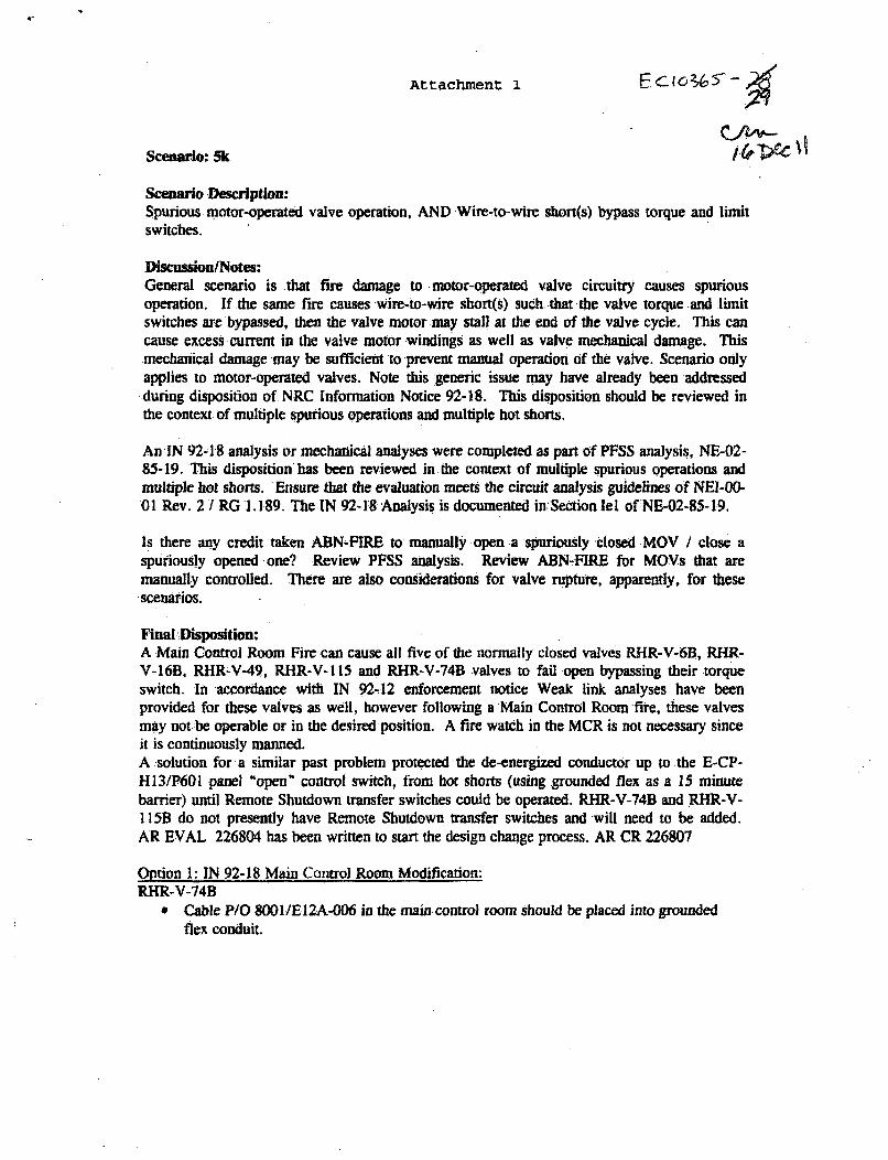
Attachment 1
Scenario: 5k
Scenanrio Description:Spurious motor-operated valve operation, AND Wire-to-wire short(s) bypass torque and limitswitches.
DiscusdonlNotes:General scenario is that fire damage to motor-operated valve circuitry causes spuriousoperation. If the same fire causes .wire;,to-wire short(s) such.,that the valve torque :and -limitswitches are bypassed, then the valve motor may stall at the end of the valve cycle. This cancause excess current in the valve motor windings as well as valve mechanical damage. Thismechanical damage may be sufficient to prevent manual operation of the valve. Scenario onlyapplies to motor-operated valves. Note this generic issue may have already been addressedduring disposition of NRC Information Notice 92-18. This disposition should be reviewed inthe context of multiple spurious operations and multiple hot shorts.
An IN 92-18 analysis or mechanical analyses were completed as part Of PFSS analysis, NE-02-85-19. This disposition has been reviewed in the context of multiple spurious operations andmultiple hot shorts. Ensure that the evaluation meets the circuit analysis guidelines of NEI-00-01 Rev. 2 1 RG 1.189. The IN 92-18 Analysis is documented in"Section lel of NE-02-85-19.
Is there any credit taken ABN-FIRE to manually open -a spuriously closed MOV / close aspuriously opened -one? Review PFSS analysis. Review ABN-FIRE for MOVs that aremanually controlled. There are also considerations for valve rupture, apparently, for thesescenarios.
Final Disposition:A Main Control Room Fire can cause all five of the normally closed valves RHR-V-6B, RHR-V-16B, RHR-V-49, RHR-V- 115 and RHR-V-74B valves to fail open bypassing their torqueswitch. In accordance with IN 92-12 enforcement notice Weak link analyses have beenprovided for these valves as well, however following a Main Control Room fire, these valvesmay not be operable or in the desired position. A fire watch in the MCR is not necessary sinceit is continuously manned.A :solution for a similar past problem protected the de-energized conductor up to the E-CP-H13/P601 panel "open" control switch, from hot shorts (using grounded flex as a 15 minutebarrier) until Remote Shutdown transfer switches could be operated. RHR-V-74B and RHR-V-115B do not presently have Remote Shutdown transfer switches and will need to be added.AR EVAL 226804 has been written to start the design change process. AR CR 226807
Option 1: IN 92-18 Main Control Room Modification:RHR-V-74B
, Cable P/O 8001/El2A-006 in the main control room should be placed into groundedflex conduit.
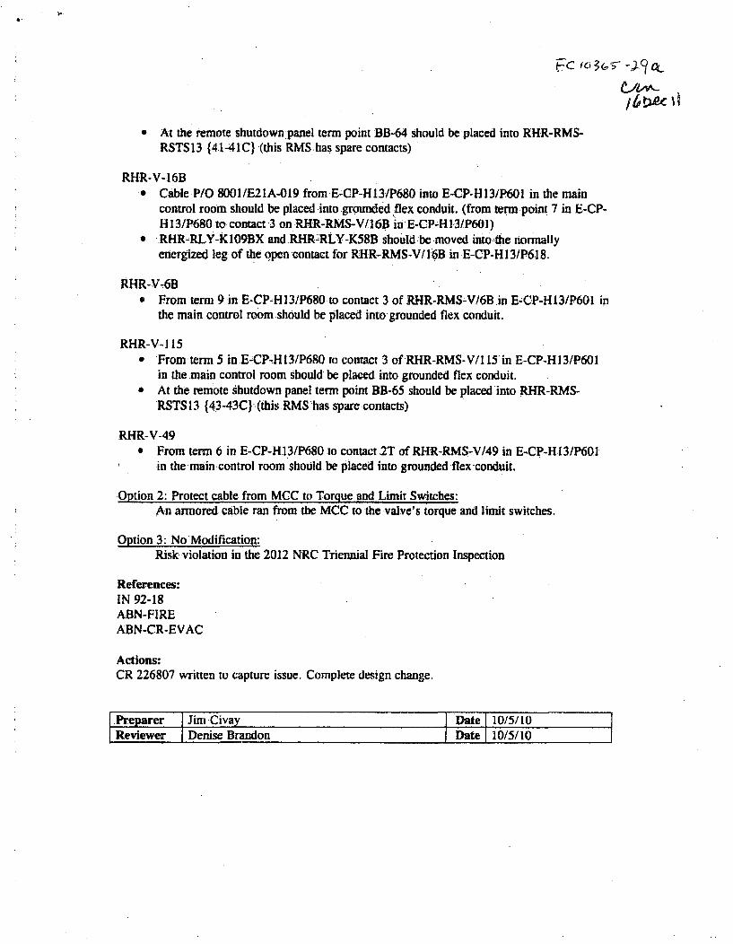
C Icl>3&t5 fa
* At the remote shutdown panel term point BB-64 should be placed into RHR-RMS-RSTS13 {41-41C} (this RMShas spare contacts)
RHR-V-16B, Cable P/O 8001/E21A-019 from E-CP-H13/P680 into E-CP-H13/P601 in the main
control room should be placed into grounded flex conduit. (from term point 7 in E-CP-H 13/P680 to contact 3 on.RHR-RMS-V/16B in E-CP-H I.3/P601)
* RHR-RLY-KIO9BX and RHR-RLY-K58B should be moved into the normallyenergized leg of the open contact for RHR-RMS-V/I:6B in E-CP-H13/P618.
RHR-V-6B* From term 9 in E-CP-H13/P680 to contact 3 of RHR-RMS-V/6B.in E-CP-H13/P601 in
the main control room should be placed into grounded flex conduit.
RHR-V-l 15" From' term 5 in .E-CP-H.13/P680 to contact 3 of RHR-RMS-V/1 15in E-CP-H13/P601
in the main control room should be placed into grounded flex conduit.* At the remote shutdown panel term point BB-65 should be placed into RFHR-RMS-
RSTS 13 {43-43C.) (this RMS 'has spare contacts)
RHR-V-49* From term 6 in E-CP-H13/P680 to contact 2T of RHR-RMS-V/49 in E&CP-H13/P60l
in the main control room. should be placed into grounded flex conduit.
Option 2: Protect cable from MCC to Torque and Limit Switches:An armored cable ran from the MCC to the valve's torque and limit switches.
Option 3: No Modification:Risk violation in the 2012 NRC Triennial Fire Protection Inspection
References:IN 92-18ABN-FIREABN-CR-EVAC
Actions:CR 226807 written to capture issue. Complete design change.
Preparer Jim Civay s Date I 10/5110Reviewer Denise Brandon Date 10/5/10