energy management for fuel-cell hybrid vehicles based on specific fuel consumption due to load...
TRANSCRIPT
1772 IEEE TRANSACTIONS ON INTELLIGENT TRANSPORTATION SYSTEMS, VOL. 13, NO. 4, DECEMBER 2012
Energy Management for Fuel-Cell Hybrid VehiclesBased on Specific Fuel Consumption
Due to Load ShiftingIsmail Levent Sarıoglu, Olaf P. Klein, Hendrik Schröder, and Ferit Küçükay
Abstract—Energy management is integral to the design offuel-cell (FC) hybrid vehicles (FCHVs), as well as topology andcomponent sizing. Therefore, an optimal energy managementstrategy is crucial for a successful FCHV concept. The goal in thisoptimization process is to coordinate the energy sources and powercomponents on a vehicle in such a way that the total consumptionis minimized. We defined a new strategy that quantifies the shiftsin the operating point (OP) of the FC system by using the specificfuel consumption due to load shifting and adapts the conditionsfor a possible shifting of the OP of the FC system to reduce thetotal fuel consumption. This paper shows the simulation resultsof the proposed strategy in comparison with existing strategies.The main focus is given on the improvement in fuel consumption,the effect of the new approach on utilization of the power sourcesconcerning their aging mechanisms, and the effect of varyingconditions by time. The results indicate that the goal of reductionin total fuel consumption is achieved.
Index Terms—Electric vehicles, energy management, fuel cells(FCs), fuel economy, hybrid power systems, vehicle dynamics.
I. INTRODUCTION
POWERTRAIN systems with hydrogen and fuel-cell (FC)technology are gaining more popularity among electric
vehicles. Despite the intensive developments in recent years,there are still some drawbacks of FC systems, which preventthem from being able to fulfill the dynamic requirements of apowertrain system alone, as explained in [1] and [2]. That iswhy building an additional reversible energy storage system tothe existing hydrogen and FC systems is necessary.
One reversible energy storage type that is popular for FChybrid vehicles (FCHVs) is the battery technology. Batteries,which are capable of performing high charging and discharg-ing rates, ensure the dynamic requirements of the powertrain
Manuscript received January 20, 2012; revised April 29, 2012; acceptedJune 5, 2012. Date of publication July 5, 2012; date of current versionNovember 27, 2012. This work was supported by Group Research, VolkswagenAG. The Associate Editor for this paper was M. Da Lio.
I. L. Sarıoglu is with the Institute of Automotive Engineering, TechnicalUniversity of Braunschweig, 38106 Braunschweig, Germany, and also withGroup Research, Volkswagen AG, 38436 Wolfsburg, Germany (e-mail: [email protected]).
O. P. Klein and H. Schröder are with Group Research, Volkswagen AG,38436 Wolfsburg, Germany.
F. Küçükay is with the Institute of Automotive Engineering, TechnicalUniversity of Braunschweig, 38106 Braunschweig, Germany.
Color versions of one or more of the figures in this paper are available onlineat http://ieeexplore.ieee.org.
Digital Object Identifier 10.1109/TITS.2012.2204878
system and allow regenerative braking. Moreover, batteries canalso contribute to the reduction of the hydrogen consumption ofthe FCHV. In this case, defining an energy management strategyfor the hybrid system is as essential as the choice of topologyand component sizing in achieving maximum fuel efficiency.
The task of the energy management is the coordination ofthe power flow in the powertrain system. Primarily, the energymanagement has to assure the drivability of the vehicle andthe reproducibility of the peak performance. To realize this,the power demand of the consumer components in the vehiclehas to be met at any time. The lifespan and durability of thecomponents need to be sustained, as well. Furthermore, energymanagement is a key factor in driving efficiency. Therefore, thepower requirements of the consumers need to be supplied in away that the total amount of the consumed energy is minimized.
One method for energy management for the powertrain sys-tems in a hybrid vehicle is based on deterministic rules, as usedin [3]–[5]. These rules are usually designed by analyzing thehybrid powertrain system or making use of human experiences,as in [6]. In [7]–[9], advanced rules, including start/stop func-tion, driving with battery power alone, and specific operatingranges defining the minimum and maximum power output forthe FC system, have also been implemented. However, themain drawback of generating deterministic rules for the energymanagement is the possibility of suboptimal conditions dueto the lacking of prior knowledge of the exact future driving.Li et al. [10] propose using various sensors and gatheringenvironment information to reduce fuel consumption.
Another strategy, which is used for energy management, isbased on fuzzy logic, as in [11]–[13]. Fuzzy logic is explainedin [14] as suitable for decision-making in complex systems withseveral variables. Depending on the scope of the predefinedrules, fuzzy logic can, most of the time, achieve the charge andhealth sustainability of the battery, but fuel economy in variousdriving conditions is still not guaranteed.
One approach that does not require the prior knowledge ofthe driving conditions is the real-time minimization of equiv-alent fuel consumption of the hybrid structure. This approachrelies on minimizing the instantaneous total consumption ofthe main power source and the equivalent fuel consumptionof the reversible energy storage system. To achieve this, anequivalent fuel consumption factor of the battery is introducedin [15]. The influence of this approach highly depends on thedefinition of the equivalence factor. In some cases, it is definedby using the efficiencies of the components, as in [16] and [17].
1524-9050/$31.00 © 2012 IEEE
SARIOGLU et al.: ENERGY MANAGEMENT FOR FCHVS BASED ON SPECIFIC FUEL CONSUMPTION 1773
Zhang and Vahidi [18] and Musardo et al. [19] utilize evenmore sophisticated methods, including probability factors, toestimate the equivalence factor. Although an improvement infuel economy has been reached, there is always an uncertaintythat the estimated equivalence factor will not meet the futureconditions of the driving. Hoffman et al. [20] shows that shiftsin the operating point (OP) of the engine do not result in areduction of total fuel consumption for a conventional hybridvehicle.
This paper deals with an alternative approach to the existingenergy management strategies for an FCHV. It is based on thespecific fuel consumption due to the shifts in the OP of theFC system. Instead of using predefined rules or equivalent fuelconsumption estimations to reduce the fuel consumption, wepropose shifting the OP of the FC system if only conditionsfor a reduction in fuel consumption are met. In this way, anadaptive load shifting strategy is achieved. We call this energymanagement strategy the adaptive load strategy (ALS).
This paper is divided into six sections, including Intro-duction. Section II describes the rule-based part of the ALS.Although it is not the primary focus in the proposed strategy,the ALS includes predefined rules. These deterministic rulesare not defined, concerning the fuel efficiency in a direct way. InSection III, which is the main focus, we combine the proposedstrategy with the concept based on specific fuel consumptiondue to load shifting. This part is described in three subsections.Section III-A mainly focuses on the definition of the specificfuel consumption due to load shifting. Section III-B explainsthe conditions for a reduction in total fuel consumption, intheory. Section III-C includes the implementation of the pro-posed strategy. Section IV introduces the modeling and testingenvironment for the ALS. The results are shown and discussedin Section V. Finally, a brief conclusion and an outlook areprovided in Section VI.
II. RULE-BASED PART OF THE ADAPTIVE LOAD STRATEGY
To begin with, it is important to mention that the rules definedhere are not proposed to optimize the power flow regarding thefuel economy. The main reason we define the following rules isto assure drivability of the vehicle, reproducibility of the peakperformance, starting of the FC system, regenerative brakingcapacity, and the long lifespan of the components.
There are four different hybrid functions that we definedby using predefined rules for the energy management of anFCHV. They are regenerative braking, dynamical boosting,power generation, and continuous boosting.
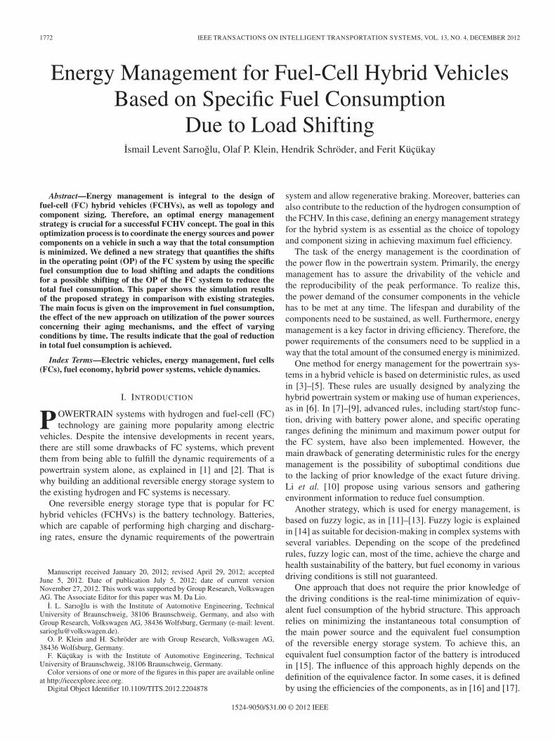
Regenerative braking is a well-known function that allowssaving the braking energy of the vehicle into the battery. The re-generative braking reduces the fuel consumption in an indirectand effective way. That is why the ALS allows the regenerativebraking for the complete state of charge (SoC) range up toSoCmax, as shown in Fig. 1. SoCmax is the highest charginglevel of the battery, which is most of the time proposed by themanufacturer to sustain the lifespan of the battery.
During driving, it is possible that the FC system is not ableto provide the desired power output in a short period of timebecause of its certain inertia or simply because of its power
Fig. 1. Rule-based hybrid functions of the ALS depending on the SOC of thebattery.
output capacity. In such cases, the ALS, with the help ofdynamical boosting, ensures that the missing power output iscovered by the battery. It is essential to deliver the power to thewheels desired by the driver. Therefore, the dynamical boostingis allowed up to a critically low SoC (see Fig. 1). The dynamicalboosting is not allowed below SoCL1 because there is a certainminimum amount of the energy capacity that should be reservedfor the next time the FC system is started.
The power generation function is activated if the SoC ofthe battery is below a certain lower level SoCL2 (see Fig. 1).The amount of the reserved charge, which this function hasto assure, is a matter of design and criteria for reproducibilityof the peak performance. In power generation, the OP of theFC system is shifted by an increasing amount (ΔPFC,gen) to ahigher value to realize a certain power flow into the battery asthe SoC of the battery falls.
It is the duty of continuous boosting to assure that thereis always a certain amount of free capacity (SoCH) in thebattery, as shown in Fig. 1. It is important and advantageousto be able to save the released energy in the next braking event.This function reduces the output of the FC system by a certainamount (ΔPFC,boost) so that the battery delivers more output.The amount of the reduction increases as the SoC increases.
The power generation and the continuous boosting are con-trolled by simple proportional controllers with relatively largeproportional bands, making them less likely to cause huntingaround the control thresholds, e.g., SoCL2 and SoCH . Fur-thermore, time constraints for switching between the functionsassure a stable system from the control point of view.
The desired energy reserves or free capacity in the batteryis defined by using various scenarios. It is important that thevehicle is capable of starting and performing its peak perfor-mance successively, even when started with relative low SoCof the battery. On the other hand, it is desired that the batteryis soon capable of saving a considerable amount of brakingenergy, even started with a relative high SoC.
III. PART OF THE ADAPTIVE LOAD STRATEGY BASED ON
SPECIFIC FUEL CONSUMPTION DUE TO LOAD SHIFTING
The power generation and continuous boosting, which aredescribed in the previous chapter, are able to sustain the SoC ofthe battery within a certain SoC window. This window betweenSoCL2 and SoCH allows a certain SoC range that is free of
1774 IEEE TRANSACTIONS ON INTELLIGENT TRANSPORTATION SYSTEMS, VOL. 13, NO. 4, DECEMBER 2012
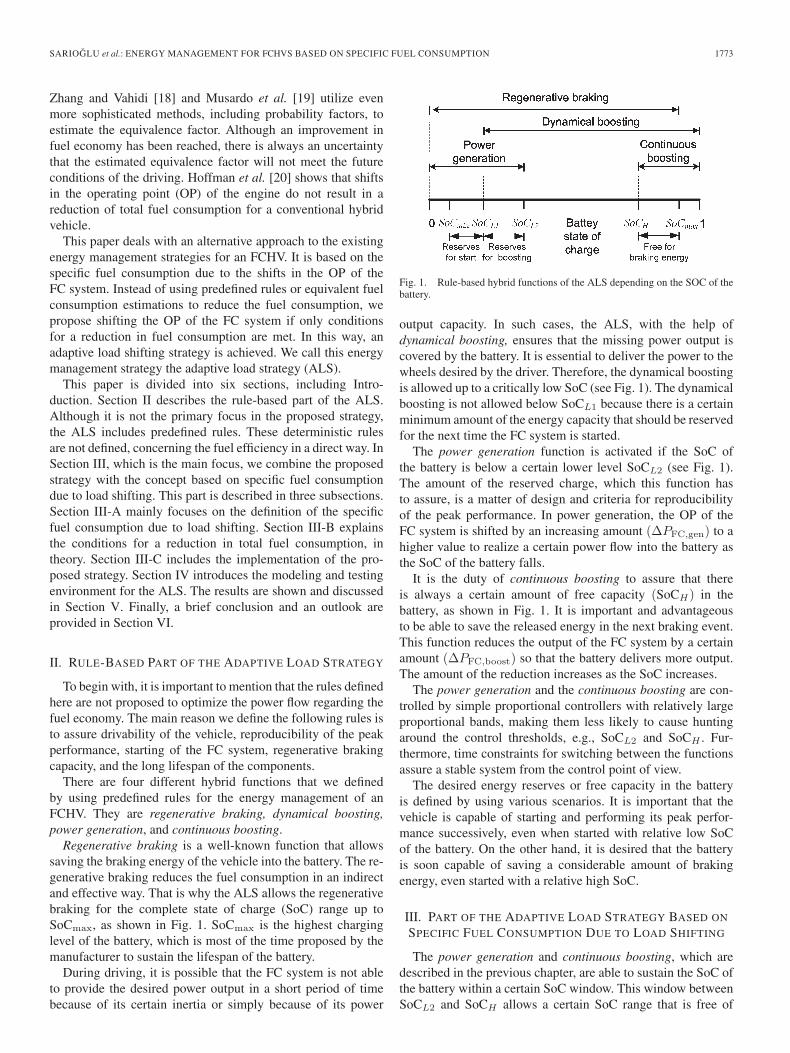
Fig. 2. Hybrid functions of the ALS based on specific fuel consumption dueto load shifting.
rule-based shifting of the OP of the FC system. The width ofthis SoC window increases the potential in reducing the fuelconsumption by using intelligent strategies for shifting the OPof the FC system. We define these limits by assuming extremedriving conditions and locate them as far as possible from eachother, as shown in Fig. 2.
Adaptive shifts in the OP of the FC system can be dividedinto two functions: shifting the OP to a higher power outputand shifting the OP to a lower power output. Both functionsare shown in Fig. 2 with the SoC ranges in which they areapplicable. The upper SoC limit of the OP shifting to a loweroutput can be extended to the SoC limits of the “continuousboosting” field because both of the functions aim to dischargethe battery. Similarly, the lower SoC limit of the OP shiftingto a higher power output can be extended up to the “powergeneration” field because of their same tendency for batterycharging. That is why both of the functions are extended andare shown with dashed lines.
To determine the necessary amount of shifting the OP, theALS uses the information based on specific fuel consumptiondue to load shifting.
A. Specific Fuel Consumption Due to Load Shifting
The procedure to evaluate the specific fuel consumption dueto load shifting requires the analysis of the change in the hydro-gen consumption rate in the case of load shifting. The hydrogenconsumption rate of an FC system mH2
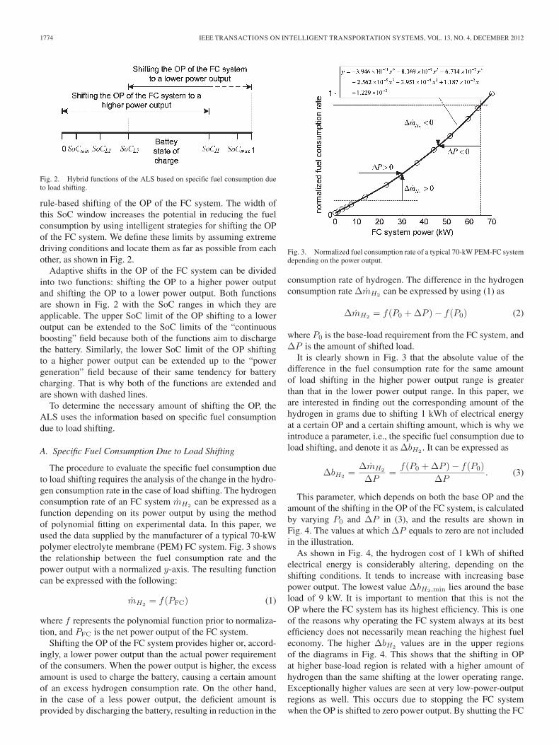
can be expressed as afunction depending on its power output by using the methodof polynomial fitting on experimental data. In this paper, weused the data supplied by the manufacturer of a typical 70-kWpolymer electrolyte membrane (PEM) FC system. Fig. 3 showsthe relationship between the fuel consumption rate and thepower output with a normalized y-axis. The resulting functioncan be expressed with the following:
mH2= f(PFC) (1)
where f represents the polynomial function prior to normaliza-tion, and PFC is the net power output of the FC system.
Shifting the OP of the FC system provides higher or, accord-ingly, a lower power output than the actual power requirementof the consumers. When the power output is higher, the excessamount is used to charge the battery, causing a certain amountof an excess hydrogen consumption rate. On the other hand,in the case of a less power output, the deficient amount isprovided by discharging the battery, resulting in reduction in the
Fig. 3. Normalized fuel consumption rate of a typical 70-kW PEM-FC systemdepending on the power output.
consumption rate of hydrogen. The difference in the hydrogenconsumption rate ΔmH2
can be expressed by using (1) as
ΔmH2= f(P0 +ΔP )− f(P0) (2)
where P0 is the base-load requirement from the FC system, andΔP is the amount of shifted load.
It is clearly shown in Fig. 3 that the absolute value of thedifference in the fuel consumption rate for the same amountof load shifting in the higher power output range is greaterthan that in the lower power output range. In this paper, weare interested in finding out the corresponding amount of thehydrogen in grams due to shifting 1 kWh of electrical energyat a certain OP and a certain shifting amount, which is why weintroduce a parameter, i.e., the specific fuel consumption due toload shifting, and denote it as ΔbH2
. It can be expressed as
ΔbH2=
ΔmH2
ΔP=
f(P0 +ΔP )− f(P0)
ΔP. (3)
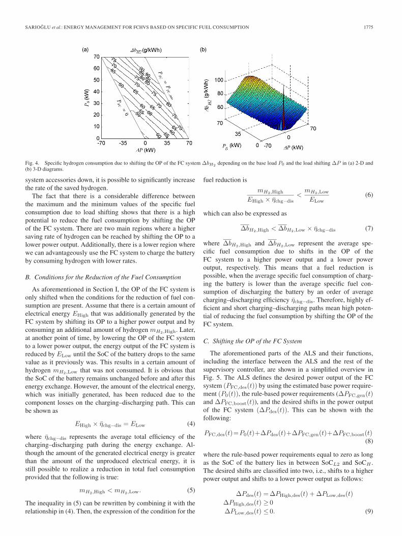
This parameter, which depends on both the base OP and theamount of the shifting in the OP of the FC system, is calculatedby varying P0 and ΔP in (3), and the results are shown inFig. 4. The values at which ΔP equals to zero are not includedin the illustration.
As shown in Fig. 4, the hydrogen cost of 1 kWh of shiftedelectrical energy is considerably altering, depending on theshifting conditions. It tends to increase with increasing basepower output. The lowest value ΔbH2,min lies around the baseload of 9 kW. It is important to mention that this is not theOP where the FC system has its highest efficiency. This is oneof the reasons why operating the FC system always at its bestefficiency does not necessarily mean reaching the highest fueleconomy. The higher ΔbH2
values are in the upper regionsof the diagrams in Fig. 4. This shows that the shifting in OPat higher base-load region is related with a higher amount ofhydrogen than the same shifting at the lower operating range.Exceptionally higher values are seen at very low-power-outputregions as well. This occurs due to stopping the FC systemwhen the OP is shifted to zero power output. By shutting the FC
SARIOGLU et al.: ENERGY MANAGEMENT FOR FCHVS BASED ON SPECIFIC FUEL CONSUMPTION 1775
Fig. 4. Specific hydrogen consumption due to shifting the OP of the FC system ΔbH2depending on the base load P0 and the load shifting ΔP in (a) 2-D and
(b) 3-D diagrams.
system accessories down, it is possible to significantly increasethe rate of the saved hydrogen.
The fact that there is a considerable difference betweenthe maximum and the minimum values of the specific fuelconsumption due to load shifting shows that there is a highpotential to reduce the fuel consumption by shifting the OPof the FC system. There are two main regions where a highersaving rate of hydrogen can be reached by shifting the OP to alower power output. Additionally, there is a lower region wherewe can advantageously use the FC system to charge the batteryby consuming hydrogen with lower rates.
B. Conditions for the Reduction of the Fuel Consumption
As aforementioned in Section I, the OP of the FC system isonly shifted when the conditions for the reduction of fuel con-sumption are present. Assume that there is a certain amount ofelectrical energy EHigh that was additionally generated by theFC system by shifting its OP to a higher power output and byconsuming an additional amount of hydrogen mH2,High. Later,at another point of time, by lowering the OP of the FC systemto a lower power output, the energy output of the FC system isreduced by ELow until the SoC of the battery drops to the samevalue as it previously was. This results in a certain amount ofhydrogen mH2,Low that was not consumed. It is obvious thatthe SoC of the battery remains unchanged before and after thisenergy exchange. However, the amount of the electrical energy,which was initially generated, has been reduced due to thecomponent losses on the charging–discharging path. This canbe shown as
EHigh × ηchg−dis = ELow (4)
where ηchg−dis represents the average total efficiency of thecharging–discharging path during the energy exchange. Al-though the amount of the generated electrical energy is greaterthan the amount of the unproduced electrical energy, it isstill possible to realize a reduction in total fuel consumptionprovided that the following is true:
mH2,High < mH2,Low. (5)
The inequality in (5) can be rewritten by combining it with therelationship in (4). Then, the expression of the condition for the
fuel reduction is
mH2,High
EHigh × ηchg−dis<
mH2,Low
ELow(6)
which can also be expressed as
ΔbH2,High < ΔbH2,Low × ηchg−dis (7)
where ΔbH2,High and ΔbH2,Low represent the average spe-cific fuel consumption due to shifts in the OP of theFC system to a higher power output and a lower poweroutput, respectively. This means that a fuel reduction ispossible, when the average specific fuel consumption of charg-ing the battery is lower than the average specific fuel con-sumption of discharging the battery by an order of averagecharging–discharging efficiency ηchg−dis. Therefore, highly ef-ficient and short charging–discharging paths mean high poten-tial of reducing the fuel consumption by shifting the OP of theFC system.
C. Shifting the OP of the FC System
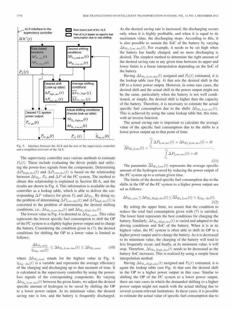
The aforementioned parts of the ALS and their functions,including the interface between the ALS and the rest of thesupervisory controller, are shown in a simplified overview inFig. 5. The ALS defines the desired power output of the FCsystem (PFC,des(t)) by using the estimated base power require-ment (P0(t)), the rule-based power requirements (ΔPFC,gen(t)and ΔPFC,boost(t)), and the desired shifts in the power outputof the FC system (ΔPdes(t)). This can be shown with thefollowing:
PFC,des(t)=P0(t)+ΔPdes(t)+ΔPFC,gen(t)+ΔPFC,boost(t)(8)
where the rule-based power requirements equal to zero as longas the SoC of the battery lies in between SoCL2 and SoCH .The desired shifts are classified into two, i.e., shifts to a higherpower output and shifts to a lower power output as follows:
ΔPdes(t) =ΔPHigh,des(t) + ΔPLow,des(t)
ΔPHigh,des(t) ≥ 0
ΔPLow,des(t) ≤ 0. (9)
1776 IEEE TRANSACTIONS ON INTELLIGENT TRANSPORTATION SYSTEMS, VOL. 13, NO. 4, DECEMBER 2012
Fig. 5. Interface between the ALS and the rest of the supervisory controllerand a simplified overview of the ALS.
The supervisory controller uses various methods to estimateP0(t). These include evaluating the driver pedals and utiliz-ing the power-loss signals from the components. DeterminingΔPHigh,des(t) and ΔPLow,des(t) is based on the relationshipbetween ΔbH2
, P0, and ΔP of the FC system. The method toobtain this relationship is explained in Section III-A, and theresults are shown in Fig. 4. This information is available on thecontroller as a lookup table, which is able to deliver the cor-responding ΔP value(s) for given P0 and ΔbH2
. By doing so,the problem of determining ΔPLow,des(t) and ΔPHigh,des(t) isconverted to the problem of determining the desired shiftingconditions, i.e., ΔbH2,Low,des(t) and ΔbH2,High,des(t).
The lowest value in Fig. 4 is denoted as ΔbH2,min. This valuerepresents the lowest specific fuel consumption to shift the OPof the FC system to a slightly higher power output and to chargethe battery. Considering the condition given in (7), the desiredconditions for shifting the OP to a lower value is limited asfollows:
ΔbH2,min
ηchg−dis(t)≤ ΔbH2,Low,des(t) ≤ ΔbH2,max (10)
where ΔbH2,max stands for the highest value in Fig. 4.ηchg−dis(t) is a variable and represents the average efficiencyof the charging and discharging up to that moment of time. Itis calculated in the supervisory controller by using the power-loss signals of the corresponding components. By varyingΔbH2,Low,des(t) between the given limits, we adjust the desiredspecific amount of hydrogen to be saved by shifting the OPto a lower power output. At its minimum value, the desiredsaving rate is low, and the battery is frequently discharged.
As the desired saving rate is increased, the discharging occursonly when it is highly profitable, and when it is equal to itsmaximum value, the discharging stops. According to this, itis also possible to sustain the SoC of the battery by varyingΔbH2,Low,des(t). For example, it needs to be set high whenthe battery has hardly charged, and no more discharging isdesired. The simplest method to determine the right amount ofthe desired saving rate at any given time between its upper andlower limits is a linear interpolation depending on the SoC ofthe battery.
Having ΔbH2,Low,des(t) assigned and P0(t) estimated, it isthe lookup table (see Fig. 4) that sets the desired shift in theOP to a lower power output. However, in some rare cases, thedesired shift and the actual shift in the power output might notbe the same, particularly when the battery is not well condi-tioned, or simply, the desired shift is higher than the capacityof the battery. Therefore, it is necessary to estimate the actualspecific fuel consumption due to the shifts ΔbH2,Low,act(t).This is achieved by using the same lookup table but, this time,with an inverse function.
The actual saving rate is important to calculate the averagevalue of the specific fuel consumption due to the shifts to alower power output up to that point of time:
ΔbH2,Low(t) =
t1∫
t2
ΔPLow,act(t)×ΔbH2,Low,act(t)× dt
t1∫
t2
ΔPLow,act(t)× dt
.
(11)The parameter ΔbH2,Low(t) represents the average specific
amount of the hydrogen saved by reducing the power output ofthe FC system up to a certain given time.
The limits of the desired specific fuel consumption due to theshifts in the OP of the FC system to a higher power output areset as follows:
ΔbH2,min≤ΔbH2,High,des(t)≤ΔbH2,Low(t)× ηchg−dis(t).(12)
By setting the upper limit, we assure that the condition toreduce the total fuel consumption given with (7) is satisfied.The lower limit represents the best conditions for charging thebattery. Similarly, ΔbH2,High,des(t) is varied and adapted to thedriving conditions and SoC of the battery. When it is at itshighest value, the FC system is often able to shift its OP to ahigher power output and to charge the battery. As it is decreasedto its minimum value, the charging of the battery will tend toless frequently occur, and finally, at its minimum value, it willstop. Therefore, ΔbH2,High,des(t) needs to be decreased as thebattery SoC increases. This is realized by using a simple linearinterpolation method.
Having ΔbH2,High,des(t) assigned and P0(t) estimated, it isagain the lookup table (see Fig. 4) that sets the desired shiftin the OP to a higher power output in this case. Similar toshifting the OP of the FC system to a lower power output,there are rare cases in which the demanded shifting to a higherpower output might not match with the actual shifting due toseveral system-relevant limitations. In these cases, it is possibleto estimate the actual value of specific fuel consumption due to
SARIOGLU et al.: ENERGY MANAGEMENT FOR FCHVS BASED ON SPECIFIC FUEL CONSUMPTION 1777
Fig. 6. Topology of the simulated FCHV.
TABLE ISIMULATED FCHV
shifting the OP to a higher power output by using the lookuptable for the actual amount of the shift. If there is a differencebetween the actual and the desired values, it is important tocheck whether the actual value ΔbH2,High,act(t) is always lowerthan the desired value ΔbH2,High,des(t), to avoid an increase intotal fuel consumption. If this is the case, the shifting to a higherpower output might still take place; if not, then the shifting to ahigher power output is stopped until the desired value is againwithin the limitations. However, it is important to notice thatthis is not a common situation in most of the driving conditions.
IV. MODELING OF THE FUEL-CELL HYBRID VEHICLE
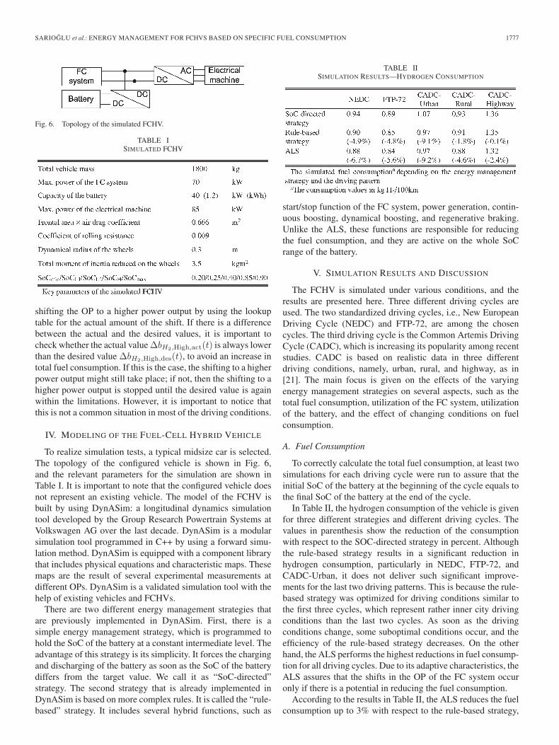
To realize simulation tests, a typical midsize car is selected.The topology of the configured vehicle is shown in Fig. 6,and the relevant parameters for the simulation are shown inTable I. It is important to note that the configured vehicle doesnot represent an existing vehicle. The model of the FCHV isbuilt by using DynASim: a longitudinal dynamics simulationtool developed by the Group Research Powertrain Systems atVolkswagen AG over the last decade. DynASim is a modularsimulation tool programmed in C++ by using a forward simu-lation method. DynASim is equipped with a component librarythat includes physical equations and characteristic maps. Thesemaps are the result of several experimental measurements atdifferent OPs. DynASim is a validated simulation tool with thehelp of existing vehicles and FCHVs.
There are two different energy management strategies thatare previously implemented in DynASim. First, there is asimple energy management strategy, which is programmed tohold the SoC of the battery at a constant intermediate level. Theadvantage of this strategy is its simplicity. It forces the chargingand discharging of the battery as soon as the SoC of the batterydiffers from the target value. We call it as “SoC-directed”strategy. The second strategy that is already implemented inDynASim is based on more complex rules. It is called the “rule-based” strategy. It includes several hybrid functions, such as
TABLE IISIMULATION RESULTS—HYDROGEN CONSUMPTION
start/stop function of the FC system, power generation, contin-uous boosting, dynamical boosting, and regenerative braking.Unlike the ALS, these functions are responsible for reducingthe fuel consumption, and they are active on the whole SoCrange of the battery.
V. SIMULATION RESULTS AND DISCUSSION
The FCHV is simulated under various conditions, and theresults are presented here. Three different driving cycles areused. The two standardized driving cycles, i.e., New EuropeanDriving Cycle (NEDC) and FTP-72, are among the chosencycles. The third driving cycle is the Common Artemis DrivingCycle (CADC), which is increasing its popularity among recentstudies. CADC is based on realistic data in three differentdriving conditions, namely, urban, rural, and highway, as in[21]. The main focus is given on the effects of the varyingenergy management strategies on several aspects, such as thetotal fuel consumption, utilization of the FC system, utilizationof the battery, and the effect of changing conditions on fuelconsumption.
A. Fuel Consumption
To correctly calculate the total fuel consumption, at least twosimulations for each driving cycle were run to assure that theinitial SoC of the battery at the beginning of the cycle equals tothe final SoC of the battery at the end of the cycle.
In Table II, the hydrogen consumption of the vehicle is givenfor three different strategies and different driving cycles. Thevalues in parenthesis show the reduction of the consumptionwith respect to the SOC-directed strategy in percent. Althoughthe rule-based strategy results in a significant reduction inhydrogen consumption, particularly in NEDC, FTP-72, andCADC-Urban, it does not deliver such significant improve-ments for the last two driving patterns. This is because the rule-based strategy was optimized for driving conditions similar tothe first three cycles, which represent rather inner city drivingconditions than the last two cycles. As soon as the drivingconditions change, some suboptimal conditions occur, and theefficiency of the rule-based strategy decreases. On the otherhand, the ALS performs the highest reductions in fuel consump-tion for all driving cycles. Due to its adaptive characteristics, theALS assures that the shifts in the OP of the FC system occuronly if there is a potential in reducing the fuel consumption.
According to the results in Table II, the ALS reduces the fuelconsumption up to 3% with respect to the rule-based strategy,
1778 IEEE TRANSACTIONS ON INTELLIGENT TRANSPORTATION SYSTEMS, VOL. 13, NO. 4, DECEMBER 2012
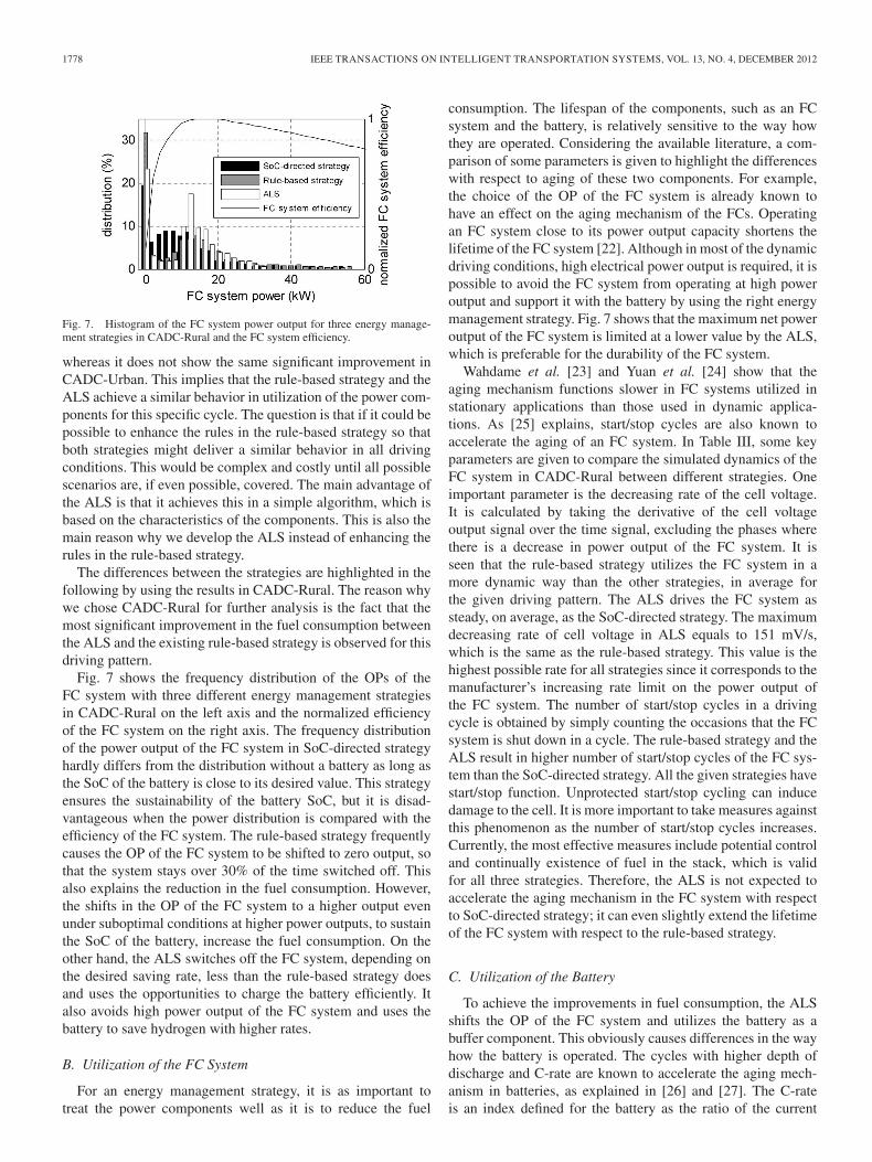
Fig. 7. Histogram of the FC system power output for three energy manage-ment strategies in CADC-Rural and the FC system efficiency.
whereas it does not show the same significant improvement inCADC-Urban. This implies that the rule-based strategy and theALS achieve a similar behavior in utilization of the power com-ponents for this specific cycle. The question is that if it could bepossible to enhance the rules in the rule-based strategy so thatboth strategies might deliver a similar behavior in all drivingconditions. This would be complex and costly until all possiblescenarios are, if even possible, covered. The main advantage ofthe ALS is that it achieves this in a simple algorithm, which isbased on the characteristics of the components. This is also themain reason why we develop the ALS instead of enhancing therules in the rule-based strategy.
The differences between the strategies are highlighted in thefollowing by using the results in CADC-Rural. The reason whywe chose CADC-Rural for further analysis is the fact that themost significant improvement in the fuel consumption betweenthe ALS and the existing rule-based strategy is observed for thisdriving pattern.
Fig. 7 shows the frequency distribution of the OPs of theFC system with three different energy management strategiesin CADC-Rural on the left axis and the normalized efficiencyof the FC system on the right axis. The frequency distributionof the power output of the FC system in SoC-directed strategyhardly differs from the distribution without a battery as long asthe SoC of the battery is close to its desired value. This strategyensures the sustainability of the battery SoC, but it is disad-vantageous when the power distribution is compared with theefficiency of the FC system. The rule-based strategy frequentlycauses the OP of the FC system to be shifted to zero output, sothat the system stays over 30% of the time switched off. Thisalso explains the reduction in the fuel consumption. However,the shifts in the OP of the FC system to a higher output evenunder suboptimal conditions at higher power outputs, to sustainthe SoC of the battery, increase the fuel consumption. On theother hand, the ALS switches off the FC system, depending onthe desired saving rate, less than the rule-based strategy doesand uses the opportunities to charge the battery efficiently. Italso avoids high power output of the FC system and uses thebattery to save hydrogen with higher rates.
B. Utilization of the FC System
For an energy management strategy, it is as important totreat the power components well as it is to reduce the fuel
consumption. The lifespan of the components, such as an FCsystem and the battery, is relatively sensitive to the way howthey are operated. Considering the available literature, a com-parison of some parameters is given to highlight the differenceswith respect to aging of these two components. For example,the choice of the OP of the FC system is already known tohave an effect on the aging mechanism of the FCs. Operatingan FC system close to its power output capacity shortens thelifetime of the FC system [22]. Although in most of the dynamicdriving conditions, high electrical power output is required, it ispossible to avoid the FC system from operating at high poweroutput and support it with the battery by using the right energymanagement strategy. Fig. 7 shows that the maximum net poweroutput of the FC system is limited at a lower value by the ALS,which is preferable for the durability of the FC system.
Wahdame et al. [23] and Yuan et al. [24] show that theaging mechanism functions slower in FC systems utilized instationary applications than those used in dynamic applica-tions. As [25] explains, start/stop cycles are also known toaccelerate the aging of an FC system. In Table III, some keyparameters are given to compare the simulated dynamics of theFC system in CADC-Rural between different strategies. Oneimportant parameter is the decreasing rate of the cell voltage.It is calculated by taking the derivative of the cell voltageoutput signal over the time signal, excluding the phases wherethere is a decrease in power output of the FC system. It isseen that the rule-based strategy utilizes the FC system in amore dynamic way than the other strategies, in average forthe given driving pattern. The ALS drives the FC system assteady, on average, as the SoC-directed strategy. The maximumdecreasing rate of cell voltage in ALS equals to 151 mV/s,which is the same as the rule-based strategy. This value is thehighest possible rate for all strategies since it corresponds to themanufacturer’s increasing rate limit on the power output ofthe FC system. The number of start/stop cycles in a drivingcycle is obtained by simply counting the occasions that the FCsystem is shut down in a cycle. The rule-based strategy and theALS result in higher number of start/stop cycles of the FC sys-tem than the SoC-directed strategy. All the given strategies havestart/stop function. Unprotected start/stop cycling can inducedamage to the cell. It is more important to take measures againstthis phenomenon as the number of start/stop cycles increases.Currently, the most effective measures include potential controland continually existence of fuel in the stack, which is validfor all three strategies. Therefore, the ALS is not expected toaccelerate the aging mechanism in the FC system with respectto SoC-directed strategy; it can even slightly extend the lifetimeof the FC system with respect to the rule-based strategy.
C. Utilization of the Battery
To achieve the improvements in fuel consumption, the ALSshifts the OP of the FC system and utilizes the battery as abuffer component. This obviously causes differences in the wayhow the battery is operated. The cycles with higher depth ofdischarge and C-rate are known to accelerate the aging mech-anism in batteries, as explained in [26] and [27]. The C-rateis an index defined for the battery as the ratio of the current
SARIOGLU et al.: ENERGY MANAGEMENT FOR FCHVS BASED ON SPECIFIC FUEL CONSUMPTION 1779
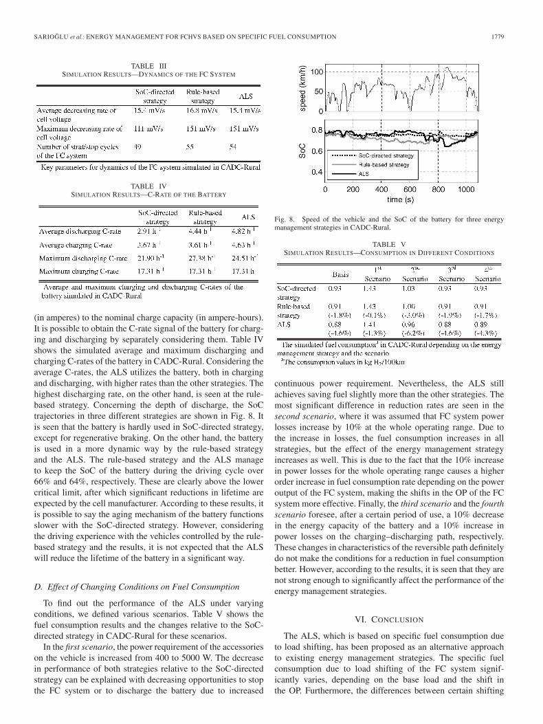
TABLE IIISIMULATION RESULTS—DYNAMICS OF THE FC SYSTEM
TABLE IVSIMULATION RESULTS—C-RATE OF THE BATTERY
(in amperes) to the nominal charge capacity (in ampere-hours).It is possible to obtain the C-rate signal of the battery for charg-ing and discharging by separately considering them. Table IVshows the simulated average and maximum discharging andcharging C-rates of the battery in CADC-Rural. Considering theaverage C-rates, the ALS utilizes the battery, both in chargingand discharging, with higher rates than the other strategies. Thehighest discharging rate, on the other hand, is seen at the rule-based strategy. Concerning the depth of discharge, the SoCtrajectories in three different strategies are shown in Fig. 8. Itis seen that the battery is hardly used in SoC-directed strategy,except for regenerative braking. On the other hand, the batteryis used in a more dynamic way by the rule-based strategyand the ALS. The rule-based strategy and the ALS manageto keep the SoC of the battery during the driving cycle over66% and 64%, respectively. These are clearly above the lowercritical limit, after which significant reductions in lifetime areexpected by the cell manufacturer. According to these results, itis possible to say the aging mechanism of the battery functionsslower with the SoC-directed strategy. However, consideringthe driving experience with the vehicles controlled by the rule-based strategy and the results, it is not expected that the ALSwill reduce the lifetime of the battery in a significant way.
D. Effect of Changing Conditions on Fuel Consumption
To find out the performance of the ALS under varyingconditions, we defined various scenarios. Table V shows thefuel consumption results and the changes relative to the SoC-directed strategy in CADC-Rural for these scenarios.
In the first scenario, the power requirement of the accessorieson the vehicle is increased from 400 to 5000 W. The decreasein performance of both strategies relative to the SoC-directedstrategy can be explained with decreasing opportunities to stopthe FC system or to discharge the battery due to increased
Fig. 8. Speed of the vehicle and the SoC of the battery for three energymanagement strategies in CADC-Rural.
TABLE VSIMULATION RESULTS—CONSUMPTION IN DIFFERENT CONDITIONS
continuous power requirement. Nevertheless, the ALS stillachieves saving fuel slightly more than the other strategies. Themost significant difference in reduction rates are seen in thesecond scenario, where it was assumed that FC system powerlosses increase by 10% at the whole operating range. Due tothe increase in losses, the fuel consumption increases in allstrategies, but the effect of the energy management strategyincreases as well. This is due to the fact that the 10% increasein power losses for the whole operating range causes a higherorder increase in fuel consumption rate depending on the poweroutput of the FC system, making the shifts in the OP of the FCsystem more effective. Finally, the third scenario and the fourthscenario foresee, after a certain period of use, a 10% decreasein the energy capacity of the battery and a 10% increase inpower losses on the charging–discharging path, respectively.These changes in characteristics of the reversible path definitelydo not make the conditions for a reduction in fuel consumptionbetter. However, according to the results, it is seen that they arenot strong enough to significantly affect the performance of theenergy management strategies.
VI. CONCLUSION
The ALS, which is based on specific fuel consumption dueto load shifting, has been proposed as an alternative approachto existing energy management strategies. The specific fuelconsumption due to load shifting of the FC system signif-icantly varies, depending on the base load and the shift inthe OP. Furthermore, the differences between certain shifting
1780 IEEE TRANSACTIONS ON INTELLIGENT TRANSPORTATION SYSTEMS, VOL. 13, NO. 4, DECEMBER 2012
conditions are high enough to decrease the total consumptionafter compensating the losses due to charging and dischargingthe battery. The ALS uses this aspect and reduces the fuelconsumption of the vehicle by adaptively shifting the OP of theFC system in all driving conditions.
Although the differences in utilization of the componentsshow that a significant loss in lifetime of the battery is notexpected, the tradeoff between the battery lifetime and the fuelconsumption for hybrid vehicles is a well-known phenomenonfor hybrid vehicles. However, this time, the benefits of theALS on the valuable FC system need to be considered aswell. Therefore, a quantitative cost-benefit analysis of the ALS,including validated aging models of the FC system and thebattery, is certainly a potential research topic.
One of the important concerns about the ALS is that themap for specific fuel consumption due to load shifting, whichis implemented on the controller, is based on an analysis ofthe FC system at the beginning of its lifetime at its idealoperating conditions. However, the environment conditions andthe specifications of the FC system vary by time. The fact thatthe inlets of the FC system are preconditioned minimizes theeffect of varying environment conditions. However, the varyingspecifications of the FC system due to aging may influence theperformance of the ALS. This strongly depends on the wayhow the relationship between the fuel consumption rate andthe power output of the FC system is changed by time. Theperformance of the ALS may still be high if the fuel con-sumption rate still performs a similar polynomial growth withincreasing power output, as assumed in the second scenarioin Section V. Therefore, it might help improve the strategy toevaluate the validity and consequences of the saved informationafter a certain period of use. If necessary, aging models withavailable on-board sensors can be used to estimate the agingeffects.
REFERENCES
[1] S. Pischinger, C. Schönfelder, and J. Ogrzewalla, “Analysis of dynamicrequirements for fuel cell systems for vehicle applications,” J. PowerSources, vol. 154, no. 2, pp. 420–427, 2006.
[2] H. Zhao and A. F. Burke, “Optimization of fuel cell system operatingconditions for fuel cell vehicles,” J. Power Sources, vol. 186, no. 2,pp. 408–416, Jan. 2009.
[3] K. Wipke, T. Markel, and D. Nelson, “Optimizing energy managementstrategy and degree of hybridization for a hydrogen fuel cell SUV,” inProc. 18th Elect. Veh. Symp., Berlin, Germany, 2001.
[4] R. K. Ahluwalia, X. Wang, and A. Rousseau, “Fuel economy of hybridfuelcell vehicles,” J. Power Sources, vol. 152, pp. 233–244, Dec. 2005.
[5] D. Feroldi, M. Serra, and J. Riera, “Energy management strategies basedon efficiency map for fuel cell hybrid vehicles,” J. Power Sources,vol. 190, no. 2, pp. 387–401, May 2009.
[6] F. R. Salmasi, “Control strategies for hybrid electric vehicles: Evolution,classification, comparison and future trends,” IEEE Trans. Veh. Technol.,vol. 56, no. 5, pp. 2393–2404, Sep. 2007.
[7] M. F. Johannaber, “Auslegung und Energiemanagement von hybri-den Brennstoffzellenfahrzeugen,” Ph.D. dissertation, Inst. Autom. Eng.,RWTH Aachen Univ., Aachen, Germany, 2010.
[8] J. Leohold, W. Steiger, T. Böhm, and L. Hofmann, “Twin Drive—EinSchritt in Richtung Elektromobilität,” in VDI-FVT-Jahrbuch.Düsseldorf, Germany: VDI, 2009, pp. 72–79.
[9] F. M. Rudolf, “Leistungs- und Effizienzoptmierung von Brennstof-fzellen_Hybridfahrzeugen,” M.S. thesis, Inst. Elect. Energy Syst.,Univ. Otto von Guericke, Magdeburg, Germany, 2010.
[10] K. Li, T. Chen, Y. Luo, and J. Wang, “Intelligent environment-friendlyvehicles: Concept and case studies,” IEEE Trans. Intell. Transp. Syst.,vol. 13, no. 1, pp. 318–328, Mar. 2012.
[11] C. Y. Li and G. P. Liu, “Optimal fuzzy power control and managementof fuel cell/battery hybrid vehicles,” J. Power Sources, vol. 192, no. 2,pp. 525–533, 2009.
[12] X. Li, X. Liangfei, J. Hua, X. Lin, J. Li, and M. Ouyang, “Powermanagement strategy for vehicular-applied hybrid fuel cell/battery powersystem,” J. Power Sources, vol. 191, no. 2, pp. 542–549, Jun. 2009.
[13] M. C. Kisacikoglu, M. Uzunoglu, and M. S. Alam, “Load sharing usingfuzzy logic control in a fuel cell/ultracapacitor hybrid vehicle,” Int. J.Hydrogen Energy, vol. 34, no. 3, pp. 1497–1507, Feb. 2009.
[14] D. Gao, Z. Jin, and Q. Lu, “Energy management strategy based on fuzzylogic for a fuel cell hybrid bus,” J. Power Sources, vol. 185, no. 1, pp. 311–337, Oct. 2008.
[15] P. Rodatz, G. Paganelli, and L. Sciarretta, “Optimal power management ofan experimental fuel cell/supercapacitor-powered hybrid vehicle,” Con-trol Eng. Pract., vol. 13, no. 1, pp. 41–53, 2005.
[16] D. Wu and S. S. Williamson, “Performance characterization and compari-son of power control strategies for fuel cell based hybrid electric vehicles,”in Proc. IEEE Veh. Power Propulsion Conf., 2007, pp. 55–61.
[17] P. Pisu and G. Rizzoni, “A supervisory control strategy for series hybridelectric vehicles with two energy storage systems,” in Proc. IEEE Veh.Power Propulsion Conf., 2005, p. 8.
[18] C. Zhang and A. Vahidi, “Real-time optimal control of plug-inhybrid vehicles with trip preview,” in Proc. Amer. Control Conf., 2010,pp. 6917–6922.
[19] C. Musardo, G. Rizzoni, and B. Staccia, “A-ECMS: An adaptive algo-rithm for hybrid electric vehicle energy management,” in Proc. DecisionControl Eur. Control Conf., 2005, pp. 1816–1823.
[20] L. Hofmann, W. Steiger, P. Adamis, and R. Petersen, “Potential and tech-nical limits of electric motors in powertrain applications/Möglichkeitenund Grenzen von Elektromaschinen im Antriebstrang,” in VDI-Berichte.Düsseldorf, Germany: VDI, 2002.
[21] M. André, “Real-world driving cycles for measuring cars pollutantemissions—Part A: The artemis European driving cycles,” INRETS,Cedex, France, Rep. INRETS-LTE 0411, 2004.
[22] R. Borup, J. Davey, D. Wood, F. Garzon, and M. Inbody, “PEM fuel celldurability,” US Dept. Energy, Hydrogen Program, Washington, DC, 2005.
[23] B. Wahdame et al., “Comparison between two PEM fuel cell durabilitytests performed at constant current and under solicitations linked to trans-port mission profile,” Int. J. Hydrogen Energy, vol. 32, no. 17, pp. 4523–4536, Dec. 2007.
[24] X. Z. Yuan, H. Li, S. Zhang, J. Martin, and H. Wang, “A review of poly-mer electrolyte membrane fuel cell durability test protocols,” J. PowerSources, vol. 196, no. 22, pp. 9107–9116, Nov. 2011.
[25] R. Borup, J. Meyers, B. Pivovar, Y. S. Kim, R. Mukundan, N. Garland,D. Myers, M. Wilson, F. Garzon, D. Wood, P. Zelenay, K. More,K. Stroh, T. Zawodzinski, J. Boncella, J. E. McGrath, M. Inaba,K. Miyatake, M. Hori, K. Ota, Z. Ogumi, S. Miyata, A. Nishikata,Z. Siroma, Y. Uchimoto, K. Yasuda, K. Kimijima, and N. Iwashita,“Scientific aspects of polymer electrolyte fuel cell durability and degra-dation,” Chem. Rev., vol. 107, no. 10, pp. 3904–3951, Oct. 2007.
[26] A. Di Filippi, S. Stockar, S. Onori, M. Canova, and Y. Guezennec,“Model-based life estimation of li-ion batteries in PHEVs using largescale vehicle simulations: An introductory study,” in Proc. IEEE Veh.Power Propulsion Conf., 2010, pp. 1–6.
[27] L. Serrao, S. Onori, A. Sciarretta, Y. Guezennec, and G. Rizzoni, “Optimalenergy management of hybrid electric vehicles including battery aging,”in Proc. ACC, 2011, pp. 2125–2130.
Ismail Levent Sarıoglu received the B.Sc. de-gree in mechanical engineering from the Mid-dle East Technical University, Ankara, Turkey, in2006 and the M.Sc. degree in automotive engi-neering from RWTH Aachen University, Aachen,Germany, in 2009. He is currently working to-ward the Ph.D. (Dr.-Ing.) degree in mechani-cal engineering with the Technical University ofBraunschweig, Braunschweig, Germany.
He is currently a Research Scientist with Volkswa-gen AG, Wolfsburg, Germany. His research interests
include alternative propulsion systems for vehicles, powertrain design, and fuelcells for automotive applications.

SARIOGLU et al.: ENERGY MANAGEMENT FOR FCHVS BASED ON SPECIFIC FUEL CONSUMPTION 1781
Olaf P. Klein received the Diplom degree in chem-istry and the Ph.D. (Dr. rer. nat.) degree in tech-nical chemistry from the Technical University ofBraunschweig, Braunschweig, Germany, in 1997and 2001, respectively.
In 2000, he joined the Group Research, Volkswa-gen AG, Wolfsburg, Germany, where he has beenengaged in several national and international projectsrelated to fuel-cell applications as both a Researcherand a Leader. He is currently a Lecturer with theTechnical University of Braunschweig and Chemnitz
University of Technology, Chemnitz, Germany. He is currently involved in theEuropean Union project HYTRAN. His research interests include fuel cells,battery chemistry, and simulation and modeling for automotive applications.
Dr. Klein is a member of the German Society for Chemical Engineering andBiotechnology.
Hendrik Schröder received the Diplom andPh.D. (Dr.-Ing.) degrees in mechanical engineeringfrom the Technical University of Braunschweig,Braunschweig, Germany, in 2005 and 2008,respectively.
Since 2005, he has been with Powertrain Sys-tems, Group Research, Volkswagen AG, Wolfsburg,Germany, where he has been engaged in researchand development of alternative powertrain systemsfor vehicles and is currently a Team Leader. He hasbeen involved with several projects related to hybrid
electrical vehicles. His research interests include conceptual design, simulation,and control of powertrain systems.
Dr. Schröder received the Hermann-Appel-Preis Award for his dissertationin 2009.
Ferit Küçükay received the Diplom and Ph.D.(Dr.-Ing.) degrees and the Habilitation from theUniversity of Technology, Munich, Germany, all inmechanical engineering, in 1977, 1981 and 1986,respectively.
In 1985, he joined the BMW AG, Munich. In1997, he joined the Institute of Automotive En-gineering, Technical University of Braunschweig,Braunschweig, Germany. He is the author or coau-thor of several books, more than 150 national andinternational publications, and patents in automotive
engineering. His research interests include vehicle dynamics and chassis, pow-ertrain systems, driver-assistance systems, objectification of subjective driver,road and vehicle parameters, and requirement engineering based on customers’use.
Prof. Küçükay is a member of the Automotive Engineering Center,Braunschweig, and the Head of the Scientific Board with the Institute forAutomotive Technology and Mobility, Germany. He is a Chair and a Member ofthe scientific and steering committees of several international symposiums andmagazines. In addition, he is a Consultant of the German Research Foundation,the German Institute for Standardization, and the German Federal MotorVehicle Registration.