energy conversion and management - soliftec · – direct energy conversion, unlike many heat...
TRANSCRIPT
Energy Conversion and Management 140 (2017) 167–181
Contents lists available at ScienceDirect
Energy Conversion and Management
journal homepage: www.elsevier .com/ locate /enconman
Review
Thermoelectric generators: A review of applications
http://dx.doi.org/10.1016/j.enconman.2017.02.0700196-8904/� 2017 Elsevier Ltd. All rights reserved.
E-mail address: [email protected]
Daniel ChampierUniv Pau & Pays Adour, Laboratoire des Sciences de l’Ingénieur Appliquées à la Mécanique et au Génie Electrique-SIAME, Fédération IPRA, EA4581, Pau, France
a r t i c l e i n f o a b s t r a c t
Article history:Received 12 July 2016Received in revised form 19 January 2017Accepted 23 February 2017
Keywords:Thermoelectric generatorsReviewThermoelectricityTEGThermoelectric modulesApplication
In past centuries, men have mainly looked to increase their production of energy in order to develop theirindustry, means of transport and quality of life. Since the recent energy crisis, researchers and industrialshave looked mainly to manage energy in a better way, especially by increasing energy system efficiency.This context explains the growing interest for thermoelectric generators.Today, thermoelectric generators allow lost thermal energy to be recovered, energy to be produced in
extreme environments, electric power to be generated in remote areas and microsensors to be powered.Direct solar thermal energy can also be used to produce electricity.This review begins with the basic principles of thermoelectricity and a presentation of existing and
future materials. Design and optimization of generators are addressed. Finally in this paper, we developedan exhaustive presentation of thermoelectric generation applications covering electricity generation inextreme environments, waste heat recovery in transport and industry, domestic production in developingand developed countries, micro-generation for sensors and microelectronics and solar thermoelectricgenerators. Many recent applications are presented, as well as the future applications which are currentlybeing studied in research laboratories or in industry. The main purpose of this paper is to clearly demon-strate that, almost anywhere in industry or in domestic uses, it is worth checking whether a TEG can beadded whenever heat is moving from a hot source to a cold source.
� 2017 Elsevier Ltd. All rights reserved.
Contents
1. Introduction and basics . . . . . . . . . . . . . . . . . . . . . . . . . . . . . . . . . . . . . . . . . . . . . . . . . . . . . . . . . . . . . . . . . . . . . . . . . . . . . . . . . . . . . . . . . . . . . . . . 1682. Materials . . . . . . . . . . . . . . . . . . . . . . . . . . . . . . . . . . . . . . . . . . . . . . . . . . . . . . . . . . . . . . . . . . . . . . . . . . . . . . . . . . . . . . . . . . . . . . . . . . . . . . . . . . . . 1693. Design and optimization . . . . . . . . . . . . . . . . . . . . . . . . . . . . . . . . . . . . . . . . . . . . . . . . . . . . . . . . . . . . . . . . . . . . . . . . . . . . . . . . . . . . . . . . . . . . . . . 1704. Applications . . . . . . . . . . . . . . . . . . . . . . . . . . . . . . . . . . . . . . . . . . . . . . . . . . . . . . . . . . . . . . . . . . . . . . . . . . . . . . . . . . . . . . . . . . . . . . . . . . . . . . . . . 171
4.1. Electricity generation in extreme environments . . . . . . . . . . . . . . . . . . . . . . . . . . . . . . . . . . . . . . . . . . . . . . . . . . . . . . . . . . . . . . . . . . . . . . . 171
4.1.1. Space exploration . . . . . . . . . . . . . . . . . . . . . . . . . . . . . . . . . . . . . . . . . . . . . . . . . . . . . . . . . . . . . . . . . . . . . . . . . . . . . . . . . . . . . . . . 1714.1.2. TEG for industrial applications in remote areas . . . . . . . . . . . . . . . . . . . . . . . . . . . . . . . . . . . . . . . . . . . . . . . . . . . . . . . . . . . . . . . . 1724.2. Waste heat recovery . . . . . . . . . . . . . . . . . . . . . . . . . . . . . . . . . . . . . . . . . . . . . . . . . . . . . . . . . . . . . . . . . . . . . . . . . . . . . . . . . . . . . . . . . . . . . 172
4.2.1. Automobile . . . . . . . . . . . . . . . . . . . . . . . . . . . . . . . . . . . . . . . . . . . . . . . . . . . . . . . . . . . . . . . . . . . . . . . . . . . . . . . . . . . . . . . . . . . . . 1724.2.2. Aircraft and helicopters . . . . . . . . . . . . . . . . . . . . . . . . . . . . . . . . . . . . . . . . . . . . . . . . . . . . . . . . . . . . . . . . . . . . . . . . . . . . . . . . . . . 1734.2.3. Ships . . . . . . . . . . . . . . . . . . . . . . . . . . . . . . . . . . . . . . . . . . . . . . . . . . . . . . . . . . . . . . . . . . . . . . . . . . . . . . . . . . . . . . . . . . . . . . . . . . 1734.2.4. Locomotive industries . . . . . . . . . . . . . . . . . . . . . . . . . . . . . . . . . . . . . . . . . . . . . . . . . . . . . . . . . . . . . . . . . . . . . . . . . . . . . . . . . . . . 1744.2.5. Recovery of waste heat in industries . . . . . . . . . . . . . . . . . . . . . . . . . . . . . . . . . . . . . . . . . . . . . . . . . . . . . . . . . . . . . . . . . . . . . . . . 1744.3. Decentralized domestic power and combined heat and power (CHP) generation systems . . . . . . . . . . . . . . . . . . . . . . . . . . . . . . . . . . . . . 174
4.3.1. Domestic TEG in developing countries . . . . . . . . . . . . . . . . . . . . . . . . . . . . . . . . . . . . . . . . . . . . . . . . . . . . . . . . . . . . . . . . . . . . . . . 1744.3.2. Domestic TEG in developed countries . . . . . . . . . . . . . . . . . . . . . . . . . . . . . . . . . . . . . . . . . . . . . . . . . . . . . . . . . . . . . . . . . . . . . . . . 1764.4. Micro-generation for sensors, microelectronics. . . . . . . . . . . . . . . . . . . . . . . . . . . . . . . . . . . . . . . . . . . . . . . . . . . . . . . . . . . . . . . . . . . . . . . . 1764.5. Solar thermoelectric generator (STEG) . . . . . . . . . . . . . . . . . . . . . . . . . . . . . . . . . . . . . . . . . . . . . . . . . . . . . . . . . . . . . . . . . . . . . . . . . . . . . . . 177
4.5.1. Special TE couples . . . . . . . . . . . . . . . . . . . . . . . . . . . . . . . . . . . . . . . . . . . . . . . . . . . . . . . . . . . . . . . . . . . . . . . . . . . . . . . . . . . . . . . 1774.5.2. Classical solar concentrators . . . . . . . . . . . . . . . . . . . . . . . . . . . . . . . . . . . . . . . . . . . . . . . . . . . . . . . . . . . . . . . . . . . . . . . . . . . . . . . 177
168 D. Champier / Energy Conversion and Management 140 (2017) 167–181
4.5.3. CHP solar systems . . . . . . . . . . . . . . . . . . . . . . . . . . . . . . . . . . . . . . . . . . . . . . . . . . . . . . . . . . . . . . . . . . . . . . . . . . . . . . . . . . . . . . . 1784.5.4. Other systems . . . . . . . . . . . . . . . . . . . . . . . . . . . . . . . . . . . . . . . . . . . . . . . . . . . . . . . . . . . . . . . . . . . . . . . . . . . . . . . . . . . . . . . . . . . 178
5. Conclusion . . . . . . . . . . . . . . . . . . . . . . . . . . . . . . . . . . . . . . . . . . . . . . . . . . . . . . . . . . . . . . . . . . . . . . . . . . . . . . . . . . . . . . . . . . . . . . . . . . . . . . . . . . 178References . . . . . . . . . . . . . . . . . . . . . . . . . . . . . . . . . . . . . . . . . . . . . . . . . . . . . . . . . . . . . . . . . . . . . . . . . . . . . . . . . . . . . . . . . . . . . . . . . . . . . . . . . . 178
1. Introduction and basics
Electricity production is an important issue for our societies.Waste heat is also an important topic. It is in this context that ther-moelectric generators (TEGs) are currently taking off. TEGs consistof a set of thermoelectric (TE) modules inserted between two heatexchangers. Each TE module is then composed of several tens tohundreds of pairs of TE couples connected together electrically inseries and thermally in parallel, which directly convert a part ofthe thermal energy that passes through them into electricity.
The advantages of TEGs are numerous:
– direct energy conversion, unlike many heat engines that firstconvert thermal energy into mechanical energy and then con-vert this mechanical energy into electricity using an alternator,
– no moving parts and no working fluids inside the TEG, hence nomaintenance and no extra costs,
– a long lifespan, especially when working with constant heatsources,
– no scale effect: TEG can be used for micro generation in verylimited spaces or to produce kilowatts,
– noiseless operations,– any working position is possible, making TEGs well suited forembedded systems.
Despite these advantages, for many years TEGs were limited tospace applications where their extreme reliability justified theiruse to provide electricity to the majority of probes sent into space(Voyager, Apollo, Pioneer, Curiosity, etc.). Low efficiency and highcost have been a barrier to their development for more commonapplications.
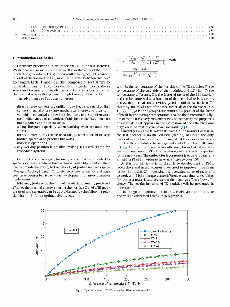
Efficiency (defined as the ratio of the electrical energy producedWelec to the thermal energy entering the hot face Qh) of a TE mod-ule used as a generator can be approximated by the following rela-tionship [1–3] for an optimal electric load:
Fig. 1. Typical values of TE efficie
gTEmax ¼Welec
QH¼ DT
TH:
ffiffiffiffiffiffiffiffiffiffiffiffiffiffiffi
1þ ZTp � 1ffiffiffiffiffiffiffiffiffiffiffiffiffiffiffi
1þ ZTp þ TC
TH
with
Z ¼ ðap � anÞ2
ððkp:qpÞ1=2 þ ðkn:qnÞ1=2Þ2
with TH the temperature of the hot side of the TE modules, TC thetemperature of the cold side of the modules, and DT = TH � TC thetemperature difference. Z is the factor of merit of the TE materialsand can be expressed as a function of the electrical resistivities qp
and qn, the thermal conductivities kp and kn and the Seebeck coeffi-cients ap and an of each of the two materials of the thermocouple.T = (TH � TC)/2 is the average temperature. ZT, product of the factorof merit by the average temperature is called the dimensionless fig-ure of merit. It is a very convenient way of comparing the propertiesof materials as it appears in the expression of the efficiency andplays an important role in power maximizing [4].
Currently available TE materials have a ZT of around 1 or less. Inthe last decades, Bismuth Telluride (Bi2Te3) has been the onlymaterial which has been used for industrial thermoelectric mod-ules. For these modules the average value of ZT is between 0.5 and0.8. Fig. 1 shows that the effective efficiency for industrial applica-tions is a few percent. ZT = 1 is the average value which is expectedfor the next years. The outlook for laboratories is to developmateri-als with a ZT of 2 in order to have an efficiency over 10%.
As this low efficiency is an obstacle to development of TEGs,researchers and manufacturers have tried to improve three mainissues: improving ZT, increasing the operating range of materialsto work with higher temperature differences and, finally, searchingfor low-cost materials to counteract the negative effect of low effi-ciency. The results in terms of TE modules will be presented inparagraph 2.
The design and optimization of TEGs is also an important issueand will be addressed briefly in paragraph 3.
ncy for different values of ZT.
D. Champier / Energy Conversion and Management 140 (2017) 167–181 169
As the different barriers that have blocked industrial develop-ment of TEGs are gradually disappearing, an exhaustive presenta-tion of TEG applications is necessary. In 2003, Riffat et al. [5]published a review, but many changes have occurred since thisdate. More recently in 2014, Zheng [6] presented a review, but only8 references were dated after 2011. Ahiska [7] also presented areview including 24 references between 2011 and 2014 but thediscussion of the applications lacks detail. As the development ofTEGs is expanding, a more recent review is required to presentthe latest applications.
In this paper, the advances in the production of new thermo-electric modules is discussed in Section 2. Section 3 presents thedesign and optimization of thermoelectric generators. Section 4provides a classification of TEG applications with a hundred refer-ences between 2011 and 2016. The applications described are bothin the form of laboratory prototypes and industrial projects ordevelopments. The outlook for these applications thanks to newmaterials is also discussed.
2. Materials
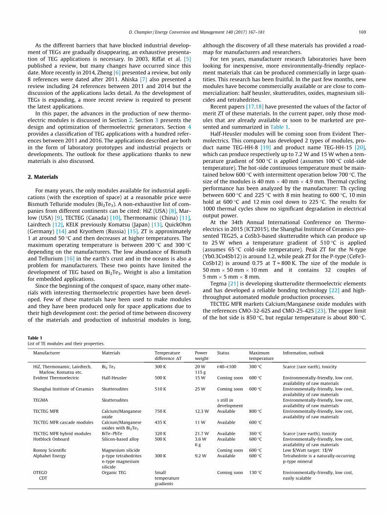
For many years, the only modules available for industrial appli-cations (with the exception of space) at a reasonable price wereBismuth Telluride modules (Bi2Te3). A non-exhaustive list of com-panies from different continents can be cited: HiZ (USA) [8], Mar-low (USA) [9], TECTEG (Canada) [10], Thermonamic (China) [11],Lairdtech [12], KELK previously Komatsu (Japan) [13], QuickOhm(Germany) [14] and Kryothem (Russia) [15]. ZT is approximately1 at around 50 �C and then decreases at higher temperatures. Themaximum operating temperature is between 200 �C and 300 �Cdepending on the manufacturers. The low abundance of Bismuthand Tellurium [16] in the earth’s crust and in the oceans is also aproblem for manufacturers. These two points have limited thedevelopment of TEG based on Bi2Te3. Weight is also a limitationfor embedded applications.
Since the beginning of the conquest of space, many other mate-rials with interesting thermoelectric properties have been devel-oped. Few of these materials have been used to make modulesand they have been produced only for space applications due totheir high development cost: the period of time between discoveryof the materials and production of industrial modules is long,
Table 1List of TE modules and their properties.
Manufacturer Materials Temperaturedifference DT
Powwei
HiZ, Thermonamic, Lairdtech,Marlow, Komatsu etc.
Bi2 Te3 300 K 20 W115
Evident Thermoelectric Half-Heusler 500 K 15 W
Shanghai Institute of Ceramics Skutterudites 510 K 25 W
TEGMA Skutterudites
TECTEG MFR Calcium/Manganeseoxide
750 K 12.3
TECTEG MFR cascade modules Calcium/Manganeseoxides with Bi2Te3
435 K 11 W
TECTEG MFR hybrid modules BiTe–PbTe 320 K 21.7Hotblock Onboard Silicon-based alloy 500 K 3.6
6 gRomny Scientific Magnesium silicideAlphabet Energy p-type tetrahedrites
n-type magnesiumsilicide
300 K 9.2
OTEGOCDT
Organic TEG Smalltemperaturegradients
although the discovery of all these materials has provided a road-map for manufacturers and researchers.
For ten years, manufacturer research laboratories have beenlooking for inexpensive, more environmentally-friendly replace-ment materials that can be produced commercially in large quan-tities. This research has been fruitful. In the past few months, newmodules have become commercially available or are close to com-mercialization: half heusler, skutterudites, oxides, magnesium sili-cides and tetrahedrites.
Recent papers [17,18] have presented the values of the factor ofmerit ZT of these materials. In the current paper, only those mod-ules that are already available or soon to be marketed are pre-sented and summarized in Table 1.
Half-Heusler modules will be coming soon from Evident Ther-molectrics. This company has developed 2 types of modules, pro-duct name TEG-HH-8 [19] and product name TEG-HH-15 [20],which can produce respectively up to 7.2 W and 15Wwhen a tem-perature gradient of 500 �C is applied (assumes 100 �C cold-sidetemperature). The hot-side continuous temperature must be main-tained below 600 �C with intermittent operation below 700 �C. Thesize of the modules is 40 mm � 40 mm � 4.9 mm. Thermal cyclingperformance has been analyzed by the manufacturer: Th cyclingbetween 600 �C and 225 �C with 8 min heating to 600 �C, 10 minhold at 600 �C and 12 min cool down to 225 �C. The results for1000 thermal cycles show no significant degradation in electricaloutput power.
At the 34th Annual International Conference on Thermo-electrics in 2015 (ICT2015), the Shanghai Institute of Ceramics pre-sented TEG25, a CoSb3-based skutterudite which can produce upto 25W when a temperature gradient of 510 �C is applied(assumes 65 �C cold-side temperature). Peak ZT for the N-type(Yb0.3Co4Sb12) is around 1.2, while peak ZT for the P-type (CeFe3-CoSb12) is around 0.75 at T = 800 K. The size of the module is50 mm � 50 mm � 10 mm and it contains 32 couples of5 mm � 5 mm � 8 mm.
Tegma [21] is developing skutterudite thermoelectric elementsand has developed a reliable bonding technology [22] and high-throughput automated module production processes.
TECTEG MFR markets Calcium/Manganese oxide modules withthe references CMO-32-62S and CMO-25-42S [23]. The upper limitof the hot side is 850 �C, but regular temperature is about 800 �C.
erght
Status Maximumtemperature
Information, outlook
g€40–€100 300 �C Scarce (rare earth), toxicity
Coming soon 600 �C Environmentally-friendly, low cost,availability of raw materials
Coming soon 600 �C Environmentally-friendly, low cost,availability of raw materials
s still indevelopment
Environmentally-friendly, low cost,availability of raw materials
W Available 800 �C Environmentally-friendly, low cost,availability of raw materials
Available 600 �C
W Available 360 �C Scarce (rare earth), toxicityW Available 600 �C Environmentally-friendly, low cost,
availability of raw materialsComing soon 600 �C Low $/Watt target: 1$/W
W Available 600 �C Tetrahedrite is a naturally-occurringp-type mineral
Coming soon 130 �C Environmentally-friendly, low cost,easily scalable
170 D. Champier / Energy Conversion and Management 140 (2017) 167–181
These modules can produce 12.3 W and 7.5 W respectively when atemperature gradient of 750 �C is applied (assumes 50 �C cold-sidetemperature). The size of the modules is 64.5 mm � 64.5 mm �8.6 mm and 42 mm � 42 mm respectively. They contain 32 cou-ples and 25 couples respectively. The 2015 price of these moduleswas around $360 and $310. This high price is far from what mightbe expected once the modules are sold in large quantities. TECTEGalso produces cascade modules: high temperature Calcium/Manganese oxides bonded with Bi2Te3 on the cold side. These arethe first cascade TE modules ever to be commercially availablewith a hot side of up to 600 �C and a cold side of up to 200 �C.The 2015 price of these modules was around $560. These modulescan produce 11W when a temperature gradient of 435 �C isapplied (assumes 45 �C cold-side temperature). The size is thesame as the CMO-32-62S.
Although they are not environmentally friendly, BiTe–PbTehybrid TE modules are also available from TECTEG. These hybridTE power modules [24] are designed with high temperature bond-ing materials that allow them to withstand temperatures of up to360 �C. These novel TEG modules work best in the 200 �C to360 �C temperature range and offer superior power output over260 �C hot side, compared to standard BiTe modules. These mod-ules can produce 21.7 W when a temperature gradient of 320 �Cis applied (assumes 30 �C cold-side temperature). The 2015 priceof these modules was around $95.
Hotblock Onboard [25] produces a module (NEMO) made of asilicon-based alloy. It delivers 3.6 W for a hot-side temperatureof 580 �C and a cold-side temperature of 80 �C. The dimensionsare 20 mm � 24 mm for a thickness of 7 mm. Samplequantities are available now. The 2014 price was around €200but should decrease considerably due to the low price andlarge quantity of materials used. These modules have verylow weight which offers interesting potential for embeddedapplications.
Romny Scientific [26] is developing TE modules made of mag-nesium silicide materials. These are low-cost, abundant raw mate-rials. The aim of this company is to develop low-cost-per-wattmodules: the target is $1/W.
Alphabet Energy [27,28] plans to produce TE modules made of anon-toxic compound: p-type tetrahedrite and n-type magnesiumsilicide (Mg2Si) pellets. Tetrahedrite is a naturally-occurringp-type mineral that exhibits a ZT of almost 1 at 720 K. MagnesiumSilicide, a non-toxic n-type compound has a ZT of 1.3 at 750 K. Thistwo compounds are compatible. One of the most appealing proper-ties of Mg2Si is its very low density (i.e. <2 g/cm3) which will bedecisive for transport applications.
General progress and interest in organic materials have con-tributed to new development for organic thermoelectric materialsespecially conductive polymers. In laboratory, conducting polymerbased on the 3,4-ethylenedioxythiophene monomer (PEDOT) [29]have reached a ZT value of 0.42 (p-type). For the n-type, value ofZT = 0.2 have been obtain with coordination polymerspoly[Kx(Ni-ett)] [30], polymers constructed from metal ions andligands, with metal ions acting as connectors and ligands as linkers.More detailed information about organic TE materials can be foundin [31,32].
These materials may be incorporated into new module designsthat take advantage of their mechanical properties despite theirlow thermoelectric properties.
These organic TE materials are limited to low temperature(<130 �C) energy harvesting. They are flexible and they can beprinted on very thin foils. These materials are easy to manufacture:printing technology are easily scalable to large areas and thisallow easy mass production at potentially low cost. They arenon-toxic.
Recently two companies arrived on the market:
– Otego [33] used a derivative of PEDOT and has deposed patentsbased on the roll-to-roll printing of organic thermoelectricmaterials. These printed ultrathin foils can be folded to producea cube of thermoelectric material, or other shapes to suit differ-ent applications.
– Cambridge Display Technology (CDT) [34] has presented flexi-ble low-cost organic TE material at Printed Electronics Confer-ence in Berlin, Germany [35].
Printed polymer TE modules can easily be shape to differentconfigurations and first calculations on optimized design havealready been done by Aranguren et al. [36].
New organic TEGs are still undergoing research but will proba-bly appear on the market in a few months. Table 1 summarizes theproperties of all these modules: the materials used, suitable tem-perature difference between the two sides of the modules, themaximum power obtained for this difference, availability of themodule, the maximum continuous working temperature and someinformation and outlook.
As can be seen, many mineral TEGs are available or comingsoon. Their new properties, such as their operating range, price,weight and non-toxicity, open up interesting prospects for large-scale industrial development.
3. Design and optimization
Industrial use of TE modules requires other elements to form apowerful generator:
– heat exchangers to amplify heat transfer between the moduleand the heat sources,
– an electrical converter to transform the electric power to a volt-age level corresponding to the storage device (batteries, capac-itors) or to the level corresponding to the needs of the end user.
The efficiency of the overall system can be defined as the ratioof the electrical energy stored or provided to the end user to theenergy consumed. The energy consumed is mainly collected atthe hot source, but can also include the mechanical energyrequired to operate the system, such as cooling of the cold heatsink or pressure losses in the heat exchangers.
This efficiency includes the efficiency of the heat exchangers,the efficiency of the TE modules, the efficiency of the electrical con-vertor and its ability to optimize the electrical load.
The performance of TE modules is low, so the design of genera-tors requires a system approach to optimize the whole system:
– Research into TE materials to achieve the highest possible ZTthroughout the generator temperature range.
– Studies on heat exchangers and coupling with TE modules.– Studies on electrical converters and on the (series, parallel ormixed) electrical connection of modules. These DC/DC convert-ers must be optimized for an electric efficiency close to 1. Boost,Buck-Boost or Cuk convertors are used depending on the outputvoltage of the TEG (which is mostly related to the number of TEmodules in series and on their characteristics) and the desiredregulated voltage for the application. They must incorporate a‘‘maximum power point tracking” (MPPT) or ‘‘maximum effi-ciency point tracking” algorithm in order to optimize the pointof electrical operation of TEGs and to transfer maximum powerto the end user. The most used MPPT algorithms for TEGs arethe perturb & observe (P&O) [37–39], the extremum seekingcontrol (ESC) [38,40], the incremental conductance (INC) [41],
D. Champier / Energy Conversion and Management 140 (2017) 167–181 171
the fractional open circuit voltage (OCV) [42,43] and the frac-tional short circuit current (ISC) [44,45]. This MPPT algorithmscan also be combined [46]. These DC/DC convertors and theirMPPT algorithms must be carefully selected according to theconfiguration of the generator and the load requirements.
– Numerical studies to optimize generators. The numerical mod-els must take account of the variations in the properties of thematerials according to temperature, the adequate quantity ofmodules, and the geometry of the modules [47–49].
Unfortunately, these aspects are not independent of each otherand overall optimization requires many interactions and powerfulcomputing tools. The economic aspect is also extremely importantand must be studied [50].
4. Applications
The conditions in which the TEG is used and the nature of theheat sources are the two parameters used as classification criteriafor the presentation of the applications in this chapter. The TEGshave therefore been grouped into five broad categories:
– electricity generation in extreme environments: the heatsources are conventional sources dedicated to TEGs,
– waste heat recovery: the objective is to optimize heat sourcesthat are generally internal combustion engines using fossilfuels,
– decentralized domestic power and combined heat and powergeneration systems: renewable energies are predominant,
– micro-generation for sensors, microelectronics: power levelsare very low and all sources of heat are acceptable,
– solar TEG: the source of energy is the sun.
In the future, it will certainly be necessary to add an applicationcategory for organic TEGs.
4.1. Electricity generation in extreme environments
Electricity production in extreme environments must meet a setof very strict specifications. These are usually critical applications
Table 2Main radioisotope thermoelectric generators and relevant mission.
Radioisotope thermoelectricgenerator RTG
Electric Powerat beginning ofmission per RTG
Couple Numberof RTG
Missi
Space Nuclear AuxiliaryPower SNAP-3
2.7 W PbTe 1 Trans
SNAP-19B RTG 28.2 W PbTe-Tags 2 Nimb
SNAP-19 RTG 42.6 W PbTe-Tags 2 Vikin2 Vikin
40.3 W PbTe-Tags 4 Pione
4 PioneSNAP-27 RTG 70 W PbSnTe Apoll
15, 16Multi-Hundred Watt
(MHW) RTG158W SiGe 3 Voyag
General Purpose HeatSource (GPHS) RTG
292W SiGe 2 Galile3 Cassin
1 Ulyss1 New
Multi-Mission RadioisotopeThermoelectricGenerator MMRTG
110 W PbTe-Tags 1 Curio
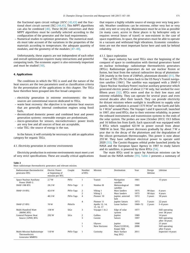
that require a highly reliable source of energy over very long peri-ods. Weather conditions can be extreme, either very hot or verycold, very wet or very dry. Maintenance must be as low as possible(in many cases, access to these places is by helicopter only orrequires several hours of travel) or non-existent in the case ofspace expeditions. In space, the generators must be able to operatein a vacuum and withstand high vibrations. Economic considera-tions are not the most important factor here and rank far behindreliability.
4.1.1. Space explorationThe space industry has used TEGs since the beginning of the
conquest of space in combination with thermal generators basedon nuclear technology: radioisotope thermoelectric generators(RTGs). Radioisotope generators do not use nuclear fission orfusion, but heat from the natural radioactive decay of plutonium-238 (mainly in the form of 238PuO2 plutonium dioxide) [51]. Thefirst use of TEG (Pb-Te) dates back to the US Navy’s Transit naviga-tion satellite (1961). The satellite was equipped with a SNAP-3(Space Nuclear Auxiliary Power) nuclear auxiliary generator whichgenerated electric power of about 2.7 W only, but worked for overfifteen years [52]. RTGs were used due to their low mass andextreme reliability. They can operate for several years and evenseveral decades after their launch. They can provide electricityfor distant missions where sunlight is insufficient to supply solarpanels. Solar radiation is around 1375W/m2 on the Earth and fallsto 1 W/m2 around Pluto. The Voyager I and II spacecraft, launchedin 1997, also used RTGs, due to their extreme reliability, to powerthe onboard instruments and transmission systems to the ends ofthe solar system. The probes are now (October 2015) 19.5 billionand 16 billion km from Earth. Each spacecraft was equipped with3 RTGs which supplied 423W in power overall from about7000W in heat. This power decreases gradually by about 7 W ayear due to the decay of the plutonium and the degradation ofthe silicon germanium thermocouples. This power is now about255W. They have sufficient electrical power to operate until2020 [53]. The Cassini-Huygens orbital probe launched jointly byNASA and the European Space Agency in 1997 to study Saturnand its satellites, is powered by three RTGs [54].
The main RTGs used in space by American missions can befound on the NASA website [55]. Table 2 presents a summary of
on Destination Year Designlifetime
Lifetime
it Navigationsatellite
1961 15 years
us III Meteorologicalsatellite
1969
g 1 Mars landers 1975 90 days 6 yearsg 2 Mars landers 1975 90 days 4 yearser 10 Jupiter, asteroid
belt1972 5 years 30 years
er 11 Jupiter Saturn 1973 5 years 22 yearso 12, 14,, 17
Lunar Surface 1969–72 2 years 5–8 years
er 1 & 2 Edge of solarsystem
1977 Still operatingover 38 years
o Jupiter 1989 14 yearsi Saturn 1997 Still operating
after 18 yearses Jupiter 1990 21 yearsHorizons Pluto(12/2014),
Kuiper Belt2006 Still operating
after 9 yearssity Mars Surface
Aug 20122011 Expected 14 years
172 D. Champier / Energy Conversion and Management 140 (2017) 167–181
the main RTGs and their missions. RTGs can also be considered acombined heat and power system because the heat generated bythe radioisotope generators keeps the embedded systems at a rea-sonable temperature when the outside temperature approaches�200 �C at the confines of the solar system.
The materials used for the thermocouples are PbSnTe, TAGS-PbTe and SiGe. Current research is focusing on improving the per-formance of proven materials (decreasing lattice conductivity andimproving electrical properties) and the study of other materialsand couple assembly (Zintl, skutterudite and segmented couples)[56–58].
In conclusion, RTGs are therefore a compact, continuous,highly-reliable source of electrical energy to explore space.
4.1.2. TEG for industrial applications in remote areasIn remote areas, the use of TEGs can produce electricity reliably
and with minimal maintenance.Historically, about a thousand radioisotope TEGs were installed
in Russia to power lighthouses and navigation beacons. Very littleinformation is available on these devices, most of which have nowbeen abandoned [59]. Today, the company Gentherm [60] (previ-ously Global Thermoelectric) is the world leader in production ofelectricity generators for remote areas. The company has existedfor 30 years and produced about 22,000 installations. These TEGsuse heat produced by the combustion of natural gas, butane or pro-pane. The burner heats one side of the lead-tin-telluride TE mod-ules directly. The other side of the modules equipped with fins iscooled by natural convection. Generators can produce between15 and 550W and can be combined for installations of up to5000 W. These TEGs are used on gas pipelines, wellheads, offshoreplatforms, telecommunications sites and for security surveillanceand monitoring.
For example, according to the datasheet, the 8550 Global Ther-moelectric model produces 500Wwith daily consumption of 38 kgof propane. Considering an average heating value of around 50 MJ/kg for propane, the energy consumed each day is in the range of1900 MJ or 528 kW h. The daily production of electricity is12 kW h. The efficiency of this small plant is around 2.3%. Thislow efficiency is offset by the benefits of the generators when theyare used in desert, well sites, offshore platforms and telecommuni-cations sites in mountains. In these locations, power availability iscritical and highly-reliable power with low maintenance isrequired whatever the climate conditions (hot, cold, wet, dry).
4.2. Waste heat recovery
Reducing greenhouse gas emissions and limiting the ecologicalfootprint are among the major challenges facing humanity in com-ing years. At the same time, power requirements are increasingevery day. A major challenge for researchers and industry is recov-ery of the lost thermal energy for conversion into electricity. TEGscan contribute to this effort. As an example, the estimation by theLawrence National Laboratory Livemore [61] of the energy used bythe United States in 2014 shows the following significant values(the unit used is the Quad, which is about 293 million MW.h.): pro-duction of 12.4 Quads of electricity for residential, commercial andindustrial consumes approximately 38.4 Quads of primary energy(mainly fossil fuels or nuclear). 25.8 quads of waste heat arereleased into the air. The transportation sector consumes 27.1quads of primary energy and 21.4 quads are released. These resultsshow the margin for progress via waste energy recovery.
The transportation industry is probably the most attractive sec-tor for use of TEGs to recover lost heat. Until now, there have beenfew solutions to recover waste heat from the exhaust gas ofengines. The most active area for energy recovery is the automo-tive sector where competition towards ever-cleaner cars is very
dynamic and encouraged by governments. The aeronautics sectoris also looking into the use of hot gases from the engines of air-planes or helicopters. Maritime transport offers interesting pro-spects due to the presence of a free cold sink (fresh water, seawater).
4.2.1. AutomobileTypically, the energy used in gasoline combustion engines
breaks down into 25% for mobility, 30% in coolant, 5% in other par-asitic losses and 40% in exhaust gas. For diesel light-duty trucksusing 100 kW of fuel power, this represents 30 kW of heat loss inexhaust gases. Converting this lost energy into electricity, evenwith efficiency of 3%, could represent 900W of electricity. Accord-ing to the Fiat Research Centre, 800–1000Wel means a reductionof 12–14 g/km CO2.
Looking at the economic context, for example in Europe, thenew CO2 emission performance standard set by the European Com-mission justifies the research efforts of manufacturers: CO2 emis-sions for passenger vehicles stood at 130 g/km in 2012 and are tobe drastically reduced to 95 g/km by 2021 (which corresponds toa consumption of about 4 L/100 km). In the case of light-dutytrucks, emissions were 175 g/km in 2014 and must drop to135 g/km by 2020. Car manufacturers will have to pay heavy finesfor vehicles exceeding the CO2 limits of the European Union. From2012, the penalty is €20 per excess gram and this value will rise to€95 per gram from 2021. The economic incentive has thereforebecome very significant.
The Fiat Research Centre [62] presented the following perfor-mance calculations. Electricity generation by an alternator is as fol-lows: chemical (fuel) energy conversion into mechanical energyhas efficiency of around 25–27%, mechanical energy conversion(alternator) into electricity is about 60%. This means that the effi-ciency of transformation of chemical energy into electrical energyis around 15–16%.
The installation of a TEG on a vehicle must meet the followingconditions. The TEG should not change the operating point of theengine; the acceptable pressure losses are very limited (around afew tens of millibars). The maximum temperature of TE materialsmust be respected and at the same time, in order to have a signif-icant temperature difference, the TEG should be operated near itslimits. It is therefore necessary to add control command (sensorsand actuators) to bypass part or all the hot gas. The materials mustbe recycled and environmentally friendly. The economic cost mustbe competitive. Many manufacturers are working on such subjects.
Gentherm (formerly Amerigon and BSST) is conducting studieson specific geometry modules for BMW and Ford [63]. The Fordgroup has been conducting research in partnership with theDepartment of Energy (DOE) of the United States. The research pro-gram was based on the installation of a TEG on a Ford Fusionequipped with a 3.0 L V6 engine [64]. The objective was to produce500W for a vehicle traveling at about 100 km/h. The results pre-sented by Maranville at the 3rd Thermoelectrics ApplicationsWorkshop in March 2012 showed generated power of about250W [65]. A bypass was installed on the exhaust system to pro-tect the generator and cooling was by means of liquid and a pump.
The BMW Group has developed various prototypes [66].In 2003, a prototype using Bi2Te3 modules produced 80 W. In
2006, a TEG equipping a BMW535i produced 200W. In 2008, onthe same vehicle, a TEG with PbTe modules produced 300W. In2011, a water-cooled prototype mounted on the exhaust of aBMW X6 produced 600W at a speed of about 125 km/h. The fuelgain was around 1.2%. Studies have also been carried out to imple-ment a TEG on the exhaust gas recirculation system (EGR). Theexhaust gas recirculation system recirculated a portion of theexhaust gas back to the engine cylinders. This device allows areduction in nitrogen oxide production, but the exhaust gas must
D. Champier / Energy Conversion and Management 140 (2017) 167–181 173
be cooled. The device therefore already contains a heat exchangerand a control valve. It is possible to add thermoelectric modules atlower cost [67].
General Motors installed a TEG on a Chevrolet Suburban[68,69]. This vehicle is comparable to a European light-duty truck,whose operating point is not too penalized by the overload due tothe TEG. The first two versions of the prototype used Bi2Te3 mod-ules. The device installed in the exhaust also included a bypass inorder to keep the temperature of the generator under 250 �C. Theexperiments first showed a significant temperature drop at theinterface between the gas and the heat exchanger, and then thatthe temperature decreased along the hot heat exchanger. At theinput of the TEG, the exhaust gas was about 400 �C and the temper-ature of the heat exchanger (which is approximately that of the hotside of the TE modules) was only 250 �C. Moreover, this tempera-ture of 250 �C at the inlet of the heat exchanger dropped to148 �C at the output of the exchanger, which is rather low.Measurement of the open circuit voltages also showed that theeffective temperature difference between the two sides of the TEmaterials was only 50 �C, far less than the temperature differencebetween the exchanger and the coolant. The first results withBi2Te3 modules were disappointing: about 25 W when the exhaustgas is around 400 �C. The problem was identified and was mostlydue to contact resistances. A new prototype using skutterudite-based modules which accept higher temperatures was studied. Afirst experiment with a reduced number of modules allowed Gen-eral Motors engineers to estimate that for a temperature differenceof about 500 �C at the inlet, a power of 230 W could be obtainedwith a complete generator.
In Europe, Renault Trucks, Volvo, supplier Valeo and academiclaboratories worked on the RENOTER ‘‘energy recovery from theexhaust of an engine thermoelectricity” project from 2008 to2011 [70,71]. The vehicles in question were cars with a 2.0 L dieselengine with a TEG (target 300 W power) installed in the exhaust,and large trucks with 11 L engines with a TEG (target 1 kW power)installed in the exhaust gas recirculation system. Significant workwas done on the design of the heat exchanger in order to optimizethe interface between the TE materials and exhaust gas. Thisexchanger causes a small pressure drop (less than 30 mbar).Non-toxic TE materials were developed by the partner laborato-ries: MnSI and Mg2Si to meet goals of moderate cost and compat-ibility with the resource volumes required for the automotivemarket. The RENOTER project concluded that a TEG with Mg2Si-MnSi materials can generate up to 130 W for a passenger car dieselexhaust in highway conditions, which remains low. However,power may rise to 250 W for gasoline passenger car exhaust and350 W for a truck exhaust gas recirculation cooler by improvingparasitic electrical resistance (contact and connections) and byimproving the performance of the p-doped material. This programis being continued with the RENOTER 2 Project which started in2013. This new program targets hybrid gasoline vehicles andindustrial vehicle exhaust gas recirculation systems. Valeo plansto produce magnesium silicide TEGs for 10,000 vehicles in 2018.
More recently, FIAT and Chrysler presented a light commercialvehicle equipped with a TEG [72–74]. The project financed by theEuropean Union was called HEATRECAR (Reduced energy con-sumption by massive thermoelectric waste heat recovery inlight-duty trucks). Work has been done on the heat exchangerand on the size of the TE modules which have been reduced(16 � 16 mm2) in order to decrease contact resistance. The perfor-mances achieved by the TEG are encouraging: a 3.9% fuel economyimprovement (6.7 g CO2/km reduction) over the worldwide har-monized light vehicles test procedure (abbreviated WLTP) cycle.This TEG used Bi2Te3 modules with limited operating tempera-tures. High-temperature material should be used in future applica-tions to take full advantage of TEG power generation. A cost
analysis of the prototype gives a current specific cost per watt ofelectricity produced of around €8.4/W. The cost breakdown analy-sis shows that 20% of the cost is due to material cost (Bi2Te3) andup to 73% of cost is due to TE module manufacturing. The maxi-mum cost accepted by the automaker in terms of €/W has beenestimated as follows:
– private conventional car or gasoline hybrid taxi: €0.5/W,– light-duty truck or freightliner in USA: €0.7/W,– diesel light-duty truck or freightliner: €1.5/W,– conventional diesel taxi: €3/W.
Scania and TitanX exhibited a heavy-duty truck at the 34thAnnual International Conference on Thermoelectrics (ICT2015)with an engine equipped with an exhaust gas recirculation system[75]. Two TEGs were present on the truck: one in the exhaust gasrecirculation system path and one in the exhaust gas path locatedafter the treatment system (ATS). The target for the sum of bothTEGs using today’s commercially-available modules was 1 kW.The measurement showed that for low engine load, most of theelectric power was produced by the TEG located after the treat-ment system but that for heavy engine load, the TEG located onthe recirculation system, produced almost the same power. Thisstudy showed the interest of combining the two systems. The mea-sured electric power reached 775W for an engine speed of1300 rpm and 100% load.
These different studies have demonstrated the technical feasi-bility of TEGs for the automobile industry, but the cost of a Bi2Te3-based TEGs is still too expensive. The roadmap for the future is todevelop TEGs with low-cost materials and with low-cost auto-mated process production.
4.2.2. Aircraft and helicoptersA significant amount of heat is released from aircraft jet engines
and turbine engines for helicopters. A preliminary study conductedby Boeing Research & Technology showed that a fuel reduction of0.5% or more is achievable with TEG. For U.S. commercial planes,a 0.5% fuel reduction means a $12 M monthly operating costreduction.
Several patents have been filed [76–78]. However, a study [79]on turbine nozzles with Bi2Te3 modules shows that the electricpower produced in real operating conditions is significant but cur-rently insufficient if the weight of the cold exchanger is included.On the turboshaft, heat can be collected on the compressor seg-ment, on the burning chamber and on the exhaust pipe. TEGs couldbe added to these different places but must have no influence onthe working point of the turboshaft, which rules out use of per-forming heat exchangers. Furthermore, heat going through theTEG must be released somewhere. Fuel, oil, air or compressed airare available, but need to be brought to the TEG, which increasesthe overall weight of the system. The integration of TEGs(0.05 kW/kg-module as state of the art) do not fulfil the powerdensity requirement (0.5 kW/kg) for aircraft. Thereafter, the Theta-gen [80] European study confirmed these results. The roadmap forthe future is probably to add the constraints of the TEG to thedesign of the aircraft engine or to add them in an area where thereis already a hot heat flow and a cold heat flow. The new light TEmaterials will also contribute, but it must be remembered thatthe weight of the heat exchanger is also to be included in the totalweight.
4.2.3. ShipsUntil now, relatively few studies have been carried out on ships
because of the absence of very strict international regulations.Shipping is a large and growing source of the greenhouse gas emis-sions that are causing climate change. The European Union wants
174 D. Champier / Energy Conversion and Management 140 (2017) 167–181
to reduce emissions from international shipping. The EuropeanCommission has proposed that owners of large ships using EUports should report their verified emissions from 2018. This sectorshould grow rapidly due to the arrival of new, more stringent rules[81]. Kristiansen [82,83] has studied the opportunity of TEGs forlarge ships. On large vessels like oil tankers, container ships, cruiseships or ocean liners, the main engine (8–80 MW) is the main heatsource on board. Traditionally, the heat released by the engine isalready used to heat heavy fuel oil and accommodation areas,and to generate fresh water. These uses decrease the temperaturesof waste heat to a level which is too low for optimal use of TEG. Onthese ships, there are also auxiliary engines but they work inter-mittently when arriving or leaving harbor and are not workingenough to produce a significant amount of energy. On these ships,there are also large incinerators to burn the sludge produced by theheavy fuel oil. The incinerator capacity in kW represents around 3%of the main engine power. These incinerators work intermittentlybut are used between 12 h and 20 h per day. The heat releasedby the incinerators is not very attractive as a heat source for theship, mainly because of the limited running time. Introducing aboiler to produce electricity calls for additional safety measures,extra installation and daily maintenance. Incinerators are thereforea good candidate for TEGs. They have a high possible temperaturedifference and the advantages of the TEG comply with design cri-teria like reliability and low maintenance.
For smaller ships, TEGs are also an opportunity because weightis not a problem, the cold source (water) is free and maintenancemust be as low as possible [81,84,85].
4.2.4. Locomotive industriesBombardier [86] has filed a patent describing a TEG with a
latent heat accumulator thermally connected to the high-temperature side of the TEG. This heat accumulator can smoothout the high temperature fluctuations which are encountered ina diesel-electric locomotive for example.
4.2.5. Recovery of waste heat in industriesIndustry is a field where heat is often a byproduct of the pro-
cess. In many cases, part of this heat is reused for heating networksor converted into electrical energy by means of steam turbines,Rankine or Stirling engines, although most of the time this heatis released into the atmosphere. Various waste heat recovery pro-jects using TEGs were studied.
In 2009, KELK Ltd. started a field test of a thermoelectric gener-ation system [87] at a carburizing furnace of Komatsu Ltd., AwazuPlant. Residual carburizing gas containing CO, H2 and N2 wasburned in the plant. This resulted in a 20 kW burning power whichconstantly heated up the hot side of a TEG. The TEG was made of 16Bi2Te3 modules and a heat exchanger which collected approxi-mately 20% of the heat (4 kW). The maximum electrical outputpower was around 214W, which represents an efficiency of 5%,but the power used to cool the cold side of the modules was notincluded in these results.
Aranguren et al. [88,89] have conducted experimental investi-gations and mathematical studies of a TEG dedicated to recoverwaste heat from a combustion chamber. In their investigation, theyincluded the energy used by the cooling system of the TEG and dis-cussed various cold heat exchangers. They have concluded thattheir prototype has potential production of 100 W/m2. This resultwas extended to a large industrial chimney on a ceramic tile fur-nace which has a flue gas mass flow of 18,400 Nm3/h and a temper-ature of 187 �C. Predicted annual electric production wasestimated to be 136 MW h per year.
The steelmaking industry produces a lot of waste heat, espe-cially radiant heat from steel products. TEGs are good candidatesto recover the radiant heat from molten metal. JFE Steel Corpora-
tion (JFE) in Japan has implemented a 10 kW TEG system (about4 m � 2 m) using radiant heat from the continuous casting slabs[90–92]. This TEG is connected to the grid. It consists of 896 TEmodules (56 TEG units of 16 Bi2Te3 TE) and outputs about 9 kWwhen the slab temperature is about 915 �C.
Cement production is also an energy-intensive industrial pro-cess. Luo et al. [93] have studied the possibility of adding TEGs toPortland cement manufacturing. They estimated that approxi-mately 10–15% of the energy is dissipated directly into the atmo-sphere through the external surface of the rotary kiln. This kindof wasted heat is difficult to recover because of the permanentmovement of the kiln. For a kiln of 4.80 m in outer diameter and72 m in length, the total heat loss without the TEG recovery systemis approximately 10,000 kW. They imagined a coaxial shell aroundthe rotary kiln covered with Bi2Te3–PbTe hybrid TE modules on theinside. They elaborated a mathematical model that predicted thatfor 20 units with 3480 TE modules (30 � 30 mm2) each, the overallTE system can produce 210 kW and save 3280 kW due to the insu-lation shell. The contribution of thermoelectric generation isapproximately 2%.
These different examples or industrial studies show that TEGshave two main prospects in industrial manufacture: either in caseswhere it is difficult to recover the waste heat by conventional sys-tems (radiated heat energy), or in the event that new materials canproduce maintenance-free and low-cost electric power, despitelow efficiency.
4.3. Decentralized domestic power and combined heat and power(CHP) generation systems
Electricity is mainly produced by centralized power stationsand distributed by grids. However, many places are not yet electri-fied. In developing countries, the combination of low powerrequirements and low population income in isolated villages pro-hibits connection to the electric grid. In developed countries, con-nection to the grid is not the most interesting solution in somecases and greener alternative solutions are being studied. For dif-ferent reasons, autonomous power production concerns bothdeveloping and developed countries. TEGs are sometimes usedonly for electricity production, but most of the current projectsconcern TEGs used in combined heat and power systems. One ofthe earliest domestic applications, a stove-top generator, was pro-posed by Killander [94] for the rural far north of Sweden. Killandernoticed that ‘‘an unverified side benefit of the generator is that itmay have decreased the amount of fuel burn”. They realized thatthe fan cooling the TEG cold side circulated the air in the roomand thus increased comfort. The system was a simplified CHPsystem.
4.3.1. Domestic TEG in developing countriesIn developing countries, an estimated 1.2 billion people – 17% of
the global population – do not have access to the electricity grid[95] and yet still have electrical needs. Biomass is the main energysource. In these rural areas, wood is burned with very low thermalefficiency – less than 10% for three-stone fire places and onlyaround 35–40% for rocket stoves and top lid updraft stoves. It con-tributes to local deforestation, increases labor for women and chil-dren and is a cause of insecurity as people collect firewood fromever further away in politically unstable countries. The fumes arealso highly toxic [96]. According to the International Health Orga-nization, the use of wood and waste for cooking and heating causes400,000 premature deaths a year in India, mostly women and chil-dren. For example, in India the amount of particles exceeds 2000 mgper cubic meter in a house where biomass is used for cooking, fargreater than the standard in the USA which is 150 mg per cubicmeter [96–98]. Installation of efficient wood stoves is critical to
D. Champier / Energy Conversion and Management 140 (2017) 167–181 175
health and safety. These efficient stoves require the use of fumeextractors to improve combustion. Electricity is therefore neces-sary both for the stoves and for the basic needs of the inhabitants.
Grid connection of villages and homes without electricity has asignificant cost with two main components: the price of the instal-lation of new power lines and the cost of electrical distributionover long distances. In 2005, the International Bank for Reconstruc-tion and Development studied the cost of installing new lines inthe state of Bahia in Brazil [99]. The cost of connecting a villagewhich is less than one kilometer from the network was estimatedbased on the number of electric poles required per capita. For onepole per household, the cost was $300. When the village is moredispersed and requires more than two poles per household, thecost increases to $1000. It soars to $4000 when more than 4 polesper household are needed. This amount increases with distanceand depends also on the nature of the terrain. The delivered costof electricity was studied in India by Nouni [100]. It varies between$0.07 and $5.1 per kW h depending on the requested peak powerand average consumption. The worst case is for a remote villagelocated at a distance of 20 km from the power line, demandingpeak power of 5 kW and with a load factor of 0.1 (ratio of averagepower to peak power). This corresponds to a village where electric-ity is mainly used for a few hours at night for lighting (villages withfew houses in mountainous areas without commercial or industrialactivity). These economic results clearly show that grid connectionis not a solution for these very low-income populations.
Power production through decentralized autonomous systemsis the only financially achievable solution. Solar energy immedi-ately springs to mind, but it requires large storage capacities forperiods without sunshine (night, fog and monsoon).
TEGs are a solution to provide a few watts for lighting or forcharging mobile phones and powering electric extractors. Thelow efficiency of the TE modules is not a problem when the contri-bution of the TEG allows an improvement of combustion efficiency.For 3 h of combustion, a family uses around 5–10 kg of wood,which means energy of around 17–34 kW h. Improving this com-bustion is a far greater contributor to reducing global energy con-sumption than the 5–30W which are produced by the TEG. In thiscase, the main specifications for the design of the TEG are to pro-vide enough electricity to power the extractor - possibly to chargea phone and give some light – and to be robust because mainte-nance is very awkward in isolated areas.
A few laboratories have conducted research into installation ofTE modules (Bi2Te3) on cookers or stoves. In the first step, thesefirst prototypes aim mainly to produce electricity. Nuwayhidet al. [101] have studied the possibility of using a proportion ofthe heat from 20–50 kW wood stoves to provide a continuous10–100W electric power supply. In a first prototype, they usedcheap Peltier modules for their TE generator. The maximum powerfor a module was very low (1 W) mostly because of the limitedtemperature difference due to the maximum temperature sup-ported by the module and also because of the geometry of thesemodules which are optimized for cooling and not for generatingpower. They already noticed the limitation of using Bi2Te3 for thisapplication. In a later prototype [102], their TE generator used 1, 2or 3 commercially-available, low-cost power generator modules.The cold side of the TE modules was cooled naturally with the sur-rounding air. They got maximum power of 4.2 W for one TE mod-ule and showed that the output power per module decreased whenthe number of TE modules in the TE generator increased. This is aresult of the reduction of the temperature difference between thehot and cold surfaces. Increasing the number of modules doesnot always increase power, as shown in Favarel [28]. They alsotried to improve heat transfer, making a TE generator using heatpipes for the heat sink [103]. The maximum power was about3.4 W. Lertsatitthanakorn [104] investigated the same type of
prototype and obtained a power output of 2.4 W. He added an eco-nomic analysis indicating that the payback period tends to be veryshort. Masbergen et al. [105,106] studied a TEG using smoke as thehot source and the outside air in forced convection as the coldsource. The electrical power obtained was of the order of 4 W afterthe DC/DC controller. Rogers and Henderson [107] have developeda portable lighting ‘‘Twig Light” for Ghana, using a few twigs toprovide half an hour of lighting. Rinalde et al. [108,109] studied aTEG using smoke as a heat source and water circulation for the coldsource. The power obtained in the laboratory with a Bi2Te3 modulewas of the order of 10 W but pump consumption was not specifiedand the electricity storage device was not yet operational. Morerecently, Shaughnessy et al. [110] have developed a TEG adaptedto portable biomass cooking stoves currently used in Malawi. Heatis collected from the fire and delivered to the hot side of the TEGthrough three copper rods which protrude into the centre of thestove. The cold side is cooled by a fan powered by the TEG. Theaim of this TEG is only to produce electricity for rural populations.Five technology-demonstrator, electricity-generating stoves havebeen integrated with locally-produced clay cooking stoves inMalawi. A 80-day field trial [111] was carried out. The data col-lected over the 80-day field trial indicates that the generators per-formed adequately and enabled the user to charge LED lights andmobile phones. These results show that the technology can supportthe energy access issue, which is around 3 W.h daily for the popu-lation in question. The authors pointed out that the air cooling sys-tem could be directed into the stove in order to improvecombustion. The TEG design has been refined based on the resultsof the field trials [112,113]. The new generator design was lessexpensive, mechanically more robust and easier to assemble thanthe initial design. A second field trial was carried out in whichsome of the TEG-stoves experienced greater cold side TEG temper-atures than expected. This was identified by the authors as beingdue to extensive use of the battery by the inhabitants. When thebattery voltage becomes too low, the fan does not cool the coldside of the TEG. This trial shows the difference between laboratorytests and field uses, and the importance of adding electronic pro-tection to the DC/DC converter.
The second and third steps for researchers were to produce elec-tricity in order to increase combustion performance by adding fansor smoke extractors and using TEGs in CHP systems. We have beenworking on such a project in our laboratory since 2009. The aim is topower a fan drawing air into the combustion chamber of a stove inorder to increase the air/fuel ratio to achieve complete combustion.The first studies showed the interest of installing the TEG betweenthe hot gas and the tank used to produce hot water [114–116]. Astove installed in our laboratory [117] has been equipped with aTEG located in the flue and acting as a heat exchanger betweenthe flue and the hotwater tank. This generator consists of two seriesof modules. The first series in the flue consists of an exchanger with4 TE modules connected electrically in series to a DC/DC converter.The second series located after the first one in the flue has a loweraverage temperature. It consists only of three TE modules in seriesin order to optimize production. These threemodules are connectedto a second DC/DC converter. The two DC/DC converters include amaximum power point tracker (MPPT) [39]. These converterscharge a battery and power the smoke extractor. Tests showedthe autonomy of the stove and the possibility of having a few extrawatts to charge a phone or for lighting.
Najjar [118] presented a multipurpose stove with a 12-moduleTEG used as a heat exchanger between the hot combustion gas andthe room air (combined heat power system). The temperature dif-ference was quite low (less than 45 K) and the peak electricalpower less than 17W for 12 modules, but the TEG improved theexchange with the air. More than 80% of the energy produced inthe combustor is transformed through TEG fins to space heating.
176 D. Champier / Energy Conversion and Management 140 (2017) 167–181
Lettsarkinon [119] studied the possibility of self-powering a ricehusk gasifier in order to use it as a cooking stove. Electrical energyis needed to drive a blower for the gasification process. The firstexperiment showed the need to improve the system as the powerproduced by the prototype was not sufficient to power the fan.Risha Mal [120,121] presented a prototype of a rudimentary cook-ing stove including a TEG. The power produced is mainly used by afan in order to improve combustion. Biolite [122] has also mar-keted a home stove which drastically reduces particulate matterand carbon emissions.
A review of the development of stove-powered TEGs can also befound in [123].
In conclusion, different systems are currently being studied andone device marketed: TEGs are a solution for providing smallamounts of electricity (mobile phone charging and LED lighting)in developing countries. They will also allow the distribution ofmore efficient stoves which need the addition of an extractor ora fan in order to improve combustion. Thermoelectric performanceis not an obstacle when set against the improvement to combus-tion efficiency which can range from 10% to 80% for multifunc-tional stoves. The main technological challenge relates to thecomplexity of combustion cycles for which maximum tempera-tures can vary greatly depending on the wood used and the habitsof the users of the stoves. These systems use Bi2Te3 modules andare undersized to withstand large variations in temperature duringwood combustion. The difficulty in disseminating this technologyis certainly also related to the cost of TEGs. The arrival of new TEmodules with extended temperature ranges and lower costsshould accelerate the development of these devices.
4.3.2. Domestic TEG in developed countriesTEGs are not limited to the domestic sector in developing coun-
tries. In developed countries, the quantity of high-performancewood stoves is increasing very quickly for economic and environ-mental reasons. These sophisticated stoves need intelligence tocontrol the combustion in order to meet minimum emissionrequirements. Electric components (sensors, fans, valves, actuatorsand microcontrollers) are necessary for these operations. Availabil-ity of electricity is essential. In the case of isolated houses used atcertain times of the year, such as second homes, the grid connec-tion can be very expensive for occasional occupants. At the sametime, the demand for comfort is there. Renewable energy fromthe sun is sometimes the answer but has the disadvantage of beingunavailable during poor weather conditions and at night, andrequiring huge batteries to store the energy whereas the heat ofthe stove can be used to generate electricity. Even in homes con-nected to the grid in some European countries, power cuts occurmore often during cold spells and people are particularly unhappyto be increasingly deprived of heating. A system guaranteeing theautonomy of the stove is a great value.
These niches have been explored by Austrian company ‘‘Bioen-ergy 2020+” which develops wood-pellet CHP combustion units[124–126]. The TE modules are arranged around the combustionchamber with an exchanger which is dimensioned to avoid exceed-ing the TE material operating range (Bi2Te3). The cold source iseither the outside air in the case of stoves used only for heating,or hot water in the case of boilers. Various prototypes have beenproduced: the TEG 250 equipped a 10 kW boiler and produced170We, the TEG400 cooled by ambient air equipped an 8 kW stoveand provided 100We, and the water-cooled TEG400 was installedon a 12 kW boiler and provided 300We. Despite these interestingresults, market production has not started, probably due to somedefects in the Bi2Te3 modules.
Montecucco et al. [127] have studied a CHP system forsolid-fuel stoves with a TEG using forced water cooling. The TEGheat exchanger system was added to the top of the stove. A pump
circulates water from a 60L water tank to the heat exchanger of theTEG cold side. A complete TEG system including an MPPT DC/DCconvertor charging a battery was experimented. Under laboratoryconditions, this device produced almost 600Wth and 27Wel onaverage during a 2-h burning experiment. Although interesting,these results will probably not be so good in real conditionsbecause of the necessity of undersizing the TEG in order to protectthe Bi2Te3 modules from overheating. Despite the great interest ofthis solution, this device adding a pump is probably a little bit toosophisticated for developing countries and is therefore presentedin the developed countries section.
Alanne et al. [128] have conceptualized a cogeneration systemin which TE material is integrated directly into the heat transfersurfaces of the combustion chamber and convection tubes of a con-ventional domestic wood-pellet-fired boiler. The aim was to findthe highest possible conversion efficiency with the slightest struc-tural change in a commercial boiler. The results of computationalanalysis should be taken with care because the model uses theproperties of Bi2Te3 at temperatures not supported by this mate-rial. However, this study shows the possibilities which can beoffered by the new materials with extended temperature ranges.
TEGs could also be developed in order to improve the efficiencyof old stoves: Ecofan [129] sell heat-powered fans for stove heaters.The airflow created by the fan distributes the warm air from thestove more evenly in the room. According to Ecofan [130], the useof an Ecofan 800 fan during woodstove operation provides an aver-age fuel saving of 14% for a range of standard test conditions studiedwhile maintaining user comfort levels over extended periods.
Adding TEG to gas heaters has been explored by Codecasa. Thefirst TEG was tested on an autonomous heat-radiating gas heaterfor commercial outdoor environments [131,132] and a power of8 W was obtained. Another prototype has been developed for gascombustion heat radiating units used in residential and industrialenvironments [133]. These heaters operate autonomously with alocal gas feed. Use of a fan convector to force air through the heatexchanger can increase comfort, reduce temperature stratification,and improve heating efficiency. The TEG can permit local produc-tion of electric power to support the fan without the need forany connection to the electricity grid.
Zheng [6,134] presented a complex domestic system combininga gas boiler and a solar concentrator with two TEG blocks. Thedomestic hot water is preheated on the cold side of the TEG units.The heat is provided either by the hot gas of the boiler or by the hotoil of the TEG. The authors have mainly conducted experiments onoil-powered TEGs.
4.4. Micro-generation for sensors, microelectronics
To be competitive, industry requires sensors in its products andin its factories. By incorporating new sensors in factories, manufac-turers can improve product quality and reduce downtime. Currentintelligent sensors require only a few hundred microwatts or a fewmilliwatts to operate. Powering these devices from the electricalgrid often requires very long cables to provide very little energy,while requiring forward planning of the layout of these cables.The power source should match the lifespan of the sensor. Mostwireless sensors are designed to last 15 years or even more, butbatteries limit this autonomy to a few years and battery changesin industrial applications are often difficult and costly due to geo-graphical constraints of access restrictions in chemical facilities,power plants (including nuclear), military facilities or secure datacenters. Manufacturers are therefore looking for micro generatorsproducing a few milliwatts to power these micro-instrumentsand make them autonomous. In factories, heat sources are numer-ous: hot fluid pipes, ovens, steam lines, motors, air conditioning,heating, ball bearing etc. TEGs are an ideal candidate for this
D. Champier / Energy Conversion and Management 140 (2017) 167–181 177
challenge. Low maintenance and good performance in difficultenvironments are also important advantages for TEGs. Very smallTEGs (a few square millimeters) are a solution to power these sen-sors permanently.
Micropelt [135] and Laird [136] are developing such devices.For example, Micropelt MPG-D751 modules with sizes of3.3 � 4.2 � 1.1 mm3 can produce more than 1 mW for a tempera-ture difference of 10 �C and more than 10 mW for a difference of30 �C. Open circuit voltage is 1 V for a temperature difference of10 �C and 3.7 V for a difference of 30 �C. The high number of cou-ples, 540 deposited on the silicon substrate, allows for high voltagelevels and facilitates DC/DC conversion. These modules are thenintegrated into various devices including hot and cold exchangers,a DC/DC converter and a storage capacitor or a small battery.Autonomous sensors and actuators are already available: theMicropelt mNODE monitors temperature continuously, and theMicropelt iTRV is a self-powered thermostatic radiator valve whichcommunicates with thermostats via standard radio protocolsenabling room temperature management. The Laird WPG-1 is aself-contained thin-film TEG that harvests waste heat to powerwireless sensors. Perpetua [137] has developed a small energy har-vester, Power Puck, which is compatible with wireless sensors andtransmitters for leading providers of wireless industrial instrumen-tation: Emerson Rosemount [138], GE Measurement & Control[139] and Honeywell Wireless. This TEG has a magnetic base andcan easily be installed on any flat metallic heat source. Power Puckallows a significant extension of battery life using energy fromtemperature differences, and allows an increase in data collectionintervals without an impact on battery life. ABB [140] also sells athermoelectric-powered temperature sensor. Wang et al. [141]studied a microTEG wireless sensor network for building energymanagement including temperature, humidity and light sensors.
Samson et al. [142–144], followed by Elefsiniotis et al. [145–147], have explored thermoelectric energy harvesting using phasechange materials (PCMs) for low-power wireless sensor systems inaircrafts. The introduction of phase change materials as a heat stor-age unit allows exploitation of temperature changes over time andcan improve these small generators. In the first prototype, thephase change material (ice water mixture) which is at the ambienttemperature inside the fuselage before the takeoff, serves as a hotspring after takeoff. The fuselage, whose temperature decreasesafter takeoff, serves as a heat sink. When taking off, the fuselagetemperature decreases quickly while the ice water mixture takesapproximately 40 min to reach the fuselage temperature. TheTEG produces enough electricity to power a microwave sensorgroup transmitting information on the fuselage structure. ThismicroTEG uses modules from Micropelt. The potential of theseTEGs has been proven over a six-month flight test campaign. Morerecently, Elefsiniotis et al. [148,149] have extended this idea toother PCM in order to use this principle in high temperature envi-ronments (aft pylon engine fairing area) in the aircraft. Shi et al.[150] studied self-powered wireless temperature sensors usingparaffin (PCM) for the cold side that can detect fire before it devel-ops to flashover state.
For extreme conditions, Xie et al. [151] have developed a TEGthat harvests seafloor hydrothermal energy through a heat pipeand converts heat to electrical energy. The TEG continuously pro-duced 2.6–3.9 W electric power during the field test, and thispower was used to power a data logger and an LED lamp. ThisTEG can be an alternative renewable power source for deep seaobservation where cable instrumentation is not practical.
Using the human body as a heat source for TEGs has also beenthe subject of several studies [152–159]. The main problem is thethermal contacts between TEG-human skin and TEG-air whichallows only a small temperature difference and limits the applica-tion to very low-power applications.
Wireless applications are growing increasingly and the electri-cal consumption of sensors, actuators and microcontrollers is con-stantly diminishing, so micro-TEGs should develop further. Thetechnology is maturing. Bi2Te3 is particularly suitable for the tem-perature ranges encountered and small amounts of materials arenot an obstacle to development. The spread of these devices willbe mainly linked to their promotion. New materials may openniches in extreme environments. Conformable Organic TE materi-als (for the human body for example) could also extend this scope.
4.5. Solar thermoelectric generator (STEG)
The basic idea is to use the sun’s heat as a heat source for theTEG. A simplified calculation neglecting Joule and Seebeck effectsallows the magnitude of heat flux density in a TE pellet to bedetermined.
Assuming that correct performance of a TEG is obtained whenthe temperature difference DT across a thermocouple is in theorder of 100 K and the length L of a thermocouple pellet is in theorder of one millimeter and the thermal conductivity k of the TEmaterials is of the order of 1 Wm�1 K�1, then the magnitude ofthe heat flux density a through a TE pellet is in the range of105W per square meter as given by the formula.
/ ¼ kDTL
¼ 11000:001
¼ 105 W=m2
However, solar intensity on earth is of the order of 103 W/m2. Itis therefore imperative to amplify this intensity by a factor of 100.Different options can be used:
– directly concentrate the solar flux received either by designingspecial TE couples with thermal and optical concentrators orby using classical solar concentrators,
– use of the TEG as a heat exchanger in a CHP system.
The waste heat on the cold side of the photovoltaic (PV) panelsor the solar heat stored in pound can also be a way to produce elec-tricity with TEG.
4.5.1. Special TE couplesThe Massachusetts Institute of Technology [160,161] has
demonstrated a flat-panel solar thermal to electric power conver-sion technology. The concentrating STEG comprises an optical con-centration system and thermal concentration absorber. A glassenclosure envelops the absorber and the TEG in order to maintaina vacuum to reduce thermal losses. The developed STEGs achievedpeak efficiency of 4.6% under 1 kWm�2 solar conditions. The diffi-culty for this kind of generator is concentrating the heat on thethermoelectric elements and finding materials that can withstandvery high temperatures (>1000 �C). Kraemer et al. [162] also pro-posed to integrate STEGs in solar hot water vacuum tube systemsfor cogeneration application, which shows potential to providecost-competitive domestic hot water and electricity. Baranowskiet al. [163] showed that, with current TE materials, a total effi-ciency of 14.1% is possible with a hot side temperature of1000 �C and a concentration of solar intensity by 100, including anon-ideal optical system. Olsen et al. planned to test a new STEGin a high-flux solar furnace in order to reach 15% efficiency. Chenet al. [164] and Kossyvakis et al. [165] also conducted calculationsto optimize STEG design.
4.5.2. Classical solar concentratorsLertsatitthanakorn et al. [166] studied a double-pass TE solar air
collector with flat plate reflectors. The flat plate reflectors wereused to concentrate solar radiation onto the TE solar air collector.The optimum position of the reflectors was studied. 2.1 Wwas pro-
178 D. Champier / Energy Conversion and Management 140 (2017) 167–181
duced. A second study [167] used a parabolic dish concentrator tocollect heat on a commercial TE module. 1.4 W was obtained.Ozdemir et al. [168] tested a prototype of solar heating TEG cooledby a chimney. 0.8 W was obtained.
4.5.3. CHP solar systemsWei He [169,170] explored the coupling of solar water heating
with a TEG. The experimental prototype unit was based on a solarconcentrator with glass evacuated tubes. The heat-pipe transfersthe solar heat absorbed within the glass evacuated tube to a waterchannel. The TEG works as a heat exchanger between the heat pipeand the water channel. Electrical efficiency is low, at around 1 to2%, but as it is a CHP system, the overall efficiency must be takenin account. The efficiency of the hot water production is quite good(about 55%). Compared to organic rankine systems, the device hasthe advantage of having no moving parts. Chavez Urbiola et al.[171,172] presented a solar hybrid electric/thermal system witha radiation concentrator. The concentrator illuminates a TEG whichis cooled by a thermosiphon providing hot water. The system gen-erates 20 W of electrical energy and 200W of thermal energystored in water with a temperature of around 50 �C.
4.5.4. Other systemsAnother idea was to add TEGs on the rear side of photovoltaic
panels to collect lost heat. The performance of this combined solarphotovoltaic and TEG system has been examined by Bjork et al.[173] using an analytical model for four different types of commer-cial photovoltaic panelss and a commercial Bi2Te3 TEG. The degra-dation of photovoltaic performance with temperature due to theTEG was shown to be much faster than the increase in power pro-duced by the TEG, due to the low efficiency of the TEG. Recently,Attivissimo et al. [174] carried out the same study and found morepromising results, whileMakki et al. [175] investigated amore com-plete system with a heat pipe removing the heat on the cold side ofthe photovoltaic -TEG system. Calculations showed an increase of1–2% in efficiency compared to a conventional photovoltaic panel.
Singh [176] experimented the use of salinity gradient solarponds which are capable of storing heat at temperatures of up to90 �C. The temperature difference between the upper convectivezone and lower convective zone of a salinity gradient solar pondcan be in the range of 40–60 �C. The designed experimental rigwas able to provide a maximum power of 34 W.
5. Conclusion
In this review of thermoelectric applications, new thermoelec-tric modules with improved ZT, larger operating range allowingtheir uses with higher temperature differences and made withlow-cost materials that counteract the negative effect of low effi-ciency of thermoelectric generators, have been presented. Startingpoints to system design have been described.
For years, the development of TEGs has been limited to Spaceand hard access areas where reliability is critical. These extremeenvironment applications have very high added value but theyare niche applications for which the market is very limited. In theseapplications, TEGs have proven their extreme reliability. Studiesconducted by the space research agencies resulted in the discoveryand development of most of the TE materials. These materials areor will be used in the industry today and in the future. However, itis very important to note that in these cases, the heat sources donot vary significantly and the materials are therefore not subjectto high thermal stress. It is quite different for others applicationspresented in this review where the temperatures of heat sourcesare changing and where the materials often experience very severetemperature cycles.
Waste heat is a big challenge in transportation and industry.TEGs are competitors which, despite their low efficiency, can con-tribute to gaining a few percent in overall efficiency and to reduc-ing the environmental footprint. Their main advantages are theircompactness and low maintenance. Different studies have demon-strated the technical feasibility of TEGs for the automobile indus-try, but the cost of a Bi2Te3-based TEGs is still too expensive.New materials characterized by low costs and larger workingranges should allow the imminent arrival of TEG on vehicles. Thesenew materials also offer very interesting perspectives for the mar-itime sector and boost research in the aircraft industry. The road-map for the future is to develop TEGs with low-cost materialsand with low-cost automated process production.
In developing and developed countries alike, the various studiesand examples presented in the review, show that TEGs are a goodsolution to provide some electricity when grid connection is notpossible. This ability to produce some electricity also improvesthe efficiency of heat generating devices slightly or consistently.The poor performance of TE materials is then masked by theimprovement in the overall system. Well-designed systems canovercome the issue of low efficiency and bring significant eco-nomic or environmental added value. The recent availability ofnew cheap materials and the starting of assembly of TE modulesby manufacturers will permit mass-market development in com-bined heat and power systems. The large-scale distribution ofthese systems will be effective once TE modules with similar prop-erties to those of Bi2Te3 will be available at low cost.
The increasing needs of self-powered micro-sensors in industrywill drive the development of micro-TEG. The sun as a free heatsource has also boosted research on solar thermoelectric genera-tors. Solar thermoelectric generators are not yet mature. Futureresearch is needed. But the availability of high-temperature TEmaterials combined with the design of high-tech TE couples inte-grating optical and thermal concentrators can be an issue in devel-oping competitive products that are comparable to photovoltaic.The use of TE modules in hybrid CHP solar systems can alsoincrease the efficiency of overall systems by a few percent. Currentresearch into organic TEGs is promising and new applications inclothes or human objects can easily be imagined.
The potential of the numerous applications described in thispaper clearly demonstrates that, almost anywhere in industry orin domestic uses, it is interesting to check whether a TEG can beadded whenever heat is moving from a hot source to a cold source.
References
[1] Rowe David M. Chapter 1. Introduction. CRC Handbook of Thermoelectrics,D. M. Rowe; 1995.
[2] Min G. In: Rowe DM, editor. Thermoelectrics Handbook Macro to Nano. CRCPress; 2006.
[3] Goldsmid HJ. Theory of Thermoelectric Refrigeration and Generation.Introduction to thermoelectricity, vol. 121. Berlin, Heidelberg: Springer;2010. p. 7–21.
[4] McCarty R. Thermoelectric power generator design for maximum power: it’sall about ZT. J Electron Mater 2013;42:1504–8. http://dx.doi.org/10.1007/s11664-012-2299-8.
[5] Riffat SB, Ma X. Thermoelectrics: a review of present and potentialapplications. Appl Therm Eng 2003;23:913–35. http://dx.doi.org/10.1016/S1359-4311(03)00012-7.
[6] Zheng XF, Liu CX, Boukhanouf R, Yan YY, Li WZ. Thermoelectrics: a review ofpresent and potential applications. Appl Therm Eng 2014;62:69–79. http://dx.doi.org/10.1016/j.applthermaleng.2013.09.008.
[7] Ahıska R, Mamur H. A review: thermoelectric generators in renewable energy.IJRER 2014;4:128–36.
[8] Hi-z.com – Home, n.d. <http://www.hi-z.com/> [accessed June 6, 2016].[9] Thermoelectric Generator (TEG) Modules|II-VI Marlow n.d. <http://
www.marlow.com/power-generators/standard-generators.html> [accessedJune 6, 2016].
[10] Tecteg Power Generator - Tecteg Power Generator.com n.d. <http://tecteg.com/> [accessed June 6, 2016].
[11] Thermonamic home page n.d. <http://www.thermonamic.com/> [accessedJune 6, 2016].
D. Champier / Energy Conversion and Management 140 (2017) 167–181 179
[12] Thermoelectric Modules|LairdTech n.d. <http://www.lairdtech.com/product-categories/thermal-management/thermoelectric-modules> [accessed June 6,2016].
[13] KELK Ltd. n.d. <http://www.kelk.co.jp/english/> [accessed June 6, 2016].[14] Quick ohm thermoelectric generator n.d. <http://www.quick-cool.com/>
[accessed June 6, 2016].[15] Kryotherm, Home Page n.d. <http://www.kryotherm.com/index.html>
[accessed June 6, 2016].[16] Gordon B, Haxel B, Hedrick JB, Orris GJ. Rare Earth Elements—Critical
Resources for High Technology|USGS Fact Sheet 087-02 n.d. <http://pubs.usgs.gov/fs/2002/fs087-02/> [accessed November 20, 2015].
[17] Chen S, Ren Z. Recent progress of half-Heusler for moderate temperaturethermoelectric applications. Mater Today 2013;16:387–95. http://dx.doi.org/10.1016/j.mattod.2013.09.015.
[18] LeBlanc S, Yee SK, Scullin ML, Dames C, Goodson KE. Material andmanufacturing cost considerations for thermoelectrics. Renew SustainEnergy Rev 2014;32:313–27. http://dx.doi.org/10.1016/j.rser.2013.12.030.
[19] TEG-HH-8_module_spec_sheet n.d. <http://www.evidentthermo.com/>[accessed June 6, 2016].
[20] TEG-HH-15_module_spec_sheet n.d. <http://www.evidentthermo.com>[accessed June 6, 2016].
[21] Tegma n.d. <http://tegma.no/> [accessed June 6, 2016].[22] Tollefsen TA, Engvoll MA, Løvvik OM, Larsson A. Method for pre-processing
semiconducting thermoelectric materials for metallization, interconnectionand bonding; 2016.
[23] tEcteg cmo-oxide-cmo-cascade-thermoelectric-power-modules n.d.<http://tecteg.com/cmo-oxide-cmo-cascade-800c-hot-side-thermoelectric-power-modules/> [accessed June 6, 2016].
[24] MODULE TEG1-PB-12611-6.0 spec sheet n.d. <http://tecteg.com/wp-content/uploads/2015/01/TEG1-PB-12611-6.0_CBH-1-Final-November-17th-update.pdf> [accessed February 9, 2015].
[25] Hotblock Onboard n.d. <http://www.hotblock.fr/> [accessed June 6, 2016].[26] Romny-scientific magnesium silicide modules n.d. <http://romny-
scientific.com> [accessed June 6, 2016].[27] Alphabet Energy’s Thermoelectric Advances - Alphabet Energy n.d. <http://
www.alphabetenergy.com/thermoelectric-advances/> [accessed June 6, 2016].[28] Green Car Congress: Alphabet Energy introduces PowerModules for modular
thermoelectric waste heat recovery; partnership with Borla for heavy-dutytrucks n.d. <http://www.greencarcongress.com/2015/06/20150624-alphabet.html> [accessed June 6, 2016].
[29] Kim G-H, Shao L, Zhang K, Pipe KP. Engineered doping of organicsemiconductors for enhanced thermoelectric efficiency. Nat Mater2013;12:719–23.
[30] Sun Y, Sheng P, Di C, Jiao F, Xu W, Qiu D, et al. Organic thermoelectricmaterials and devices based on p- and n-Type Poly(metal 1,1,2,2-ethenetetrathiolate)s. Adv Mater 2012;24:932–7. http://dx.doi.org/10.1002/adma.201104305.
[31] Zhang Q, Sun Y, Xu W, Zhu D. Organic thermoelectric materials: emerginggreen energy materials converting heat to electricity directly and efficiently.Adv Mater 2014;26:6829–51. http://dx.doi.org/10.1002/adma.201305371.
[32] Culebras M, Gómez CM, Cantarero A. Review on polymers for thermoelectricapplications. Materials 2014;7:6701. http://dx.doi.org/10.3390/ma7096701.
[33] Thermoelectric Generators (TEG) for Energy Harvesting Applications|otego n.d. <http://www.otego.de/en/> [accessed November 7, 2016].
[34] Energy harvesting and storage | CDT Ltd n.d. <https://www.cdtltd.co.uk/technology-scope/energy-harvesting-and-storage/> [accessed November 7,2016].
[35] Nikolaenko A, Anderson G, Fletcher T, King S. Progress on flexible low-costorganic thermoelectric material and device development at CDT PrintedElectronics Europe. IDTechEX; 2016.
[36] Aranguren P, Roch A, Stepien L, Abt M, von Lukowicz M, Dani I, et al.Optimized design for flexible polymer thermoelectric generators. ApplTherm Eng 2016;102:402–11. http://dx.doi.org/10.1016/j.applthermaleng.2016.03.037.
[37] Yu C, Chau KT. Thermoelectric automotive waste heat energy recovery usingmaximum power point tracking. Energy Convers Manage 2009;50:1506–12.http://dx.doi.org/10.1016/j.enconman.2009.02.015.
[38] Maganga O, Phillip N, Burnham K, Montecucco A, Siviter J, Knox A, et al.Hardware implementation of maximum power point tracking forthermoelectric generators. J Electron Mater 2014;43:2293–300. http://dx.doi.org/10.1007/s11664-014-3046-0.
[39] Champier D, Favarel C, Bedecarrats JP, Kousksou T, Rozis JF. Prototypecombined heater/thermoelectric power generator for remote applications. JElectron Mater 2013:1–12. http://dx.doi.org/10.1007/s11664-012-2459-x.
[40] Phillip N, Maganga O, Burnham KJ, Ellis MA, Robinson S, Dunn J, et al.Investigation of maximum power point tracking for thermoelectricgenerators. J Electron Mater 2013;42:1900–6. http://dx.doi.org/10.1007/s11664-012-2460-4.
[41] Kim R-Y, Lai J-S, York B, Koran A. Analysis and design of maximum powerpoint tracking scheme for thermoelectric battery energy storage system. IEEETrans Industr Electron 2009;56:3709–16. http://dx.doi.org/10.1109/TIE.2009.2025717.
[42] Montecucco A, Siviter J, Knox A. Simple, fast and accurate maximum powerpoint tracking converter for thermoelectric generators. In: Energy ConversionCongress and Exposition (ECCE), 2012 IEEE. IEEE; 2012. p. 2777–83. http://dx.doi.org/10.1109/ECCE.2012.6342530.
[43] Montecucco A, Knox AR. Maximum power point tracking converterbased on the open-circuit voltage method for thermoelectric generators.IEEE Trans Power Electron 2015;30:828–39. http://dx.doi.org/10.1109/TPEL.2014.2313294.
[44] Laird I, Lu DD-C. High step-up DC/DC topology and MPPT algorithm for usewith a thermoelectric generator. IEEE Trans Power Electron2013;28:3147–57. http://dx.doi.org/10.1109/TPEL.2012.2219393.
[45] Laird I, Lovatt H, Savvides N, Lu D, Agelidis VG. Comparative study ofmaximum power point tracking algorithms for thermoelectric generators. In:Power Engineering Conference, 2008. AUPEC ’08. Australasian Universities;2008. p. 1–6.
[46] Liu Y-H, Chiu Y-H, Huang J-W, Wang S-C. A novel maximum power pointtracker for thermoelectric generation system. Renewable Energy2016;97:306–18. http://dx.doi.org/10.1016/j.renene.2016.05.001.
[47] Montecucco A, Knox AR. Accurate simulation of thermoelectric powergenerating systems. Appl Energy 2014;118:166–72. http://dx.doi.org/10.1016/j.apenergy.2013.12.028.
[48] Montecucco A, Siviter J, Knox AR. Constant heat characterisation andgeometrical optimisation of thermoelectric generators. Appl Energy2015;149:248–58. http://dx.doi.org/10.1016/j.apenergy.2015.03.120.
[49] Favarel C, Bédécarrats J-P, Kousksou T, Champier D. Numerical optimizationof the occupancy rate of thermoelectric generators to produce the highestelectrical power. Energy 2014;68:104–16. http://dx.doi.org/10.1016/j.energy.2014.02.030.
[50] Yee SK, LeBlanc S, Goodson KE, Dames C. $ per W metrics for thermoelectricpower generation: beyond ZT. Energy Environ Sci 2013;6:2561–71. http://dx.doi.org/10.1039/C3EE41504J.
[51] Cataldo RL, Bennett GL. U.S. space radioisotope power systems andapplications: past, present and future, radioisotopes - applications inphysical sciences; 2011.
[52] Schwartz LI, Shure HJ. Survey of electric power plants for space applications.In: Fifty-Eight National Meeting of the American Institute of ChemicalEngineers Philadelphia, Pennsylvania, December 5–9, 1965.
[53] Voyager, the interstellar mission n.d. <http://voyager.jpl.nasa.gov/spacecraft/index.html> [accessed September 24, 2015].
[54] Spacecraft Power for Cassini - NASA fact sheet; 1999.[55] Radioisotope Thermoelectric Generator n.d. <http://solarsystem.nasa.gov/
rps/rtg.cfm> [accessed September 24, 2015].[56] Caillat T, Sakamoto J, Jewell A, Huang CK, Cheng J, Paik J, et al. Status of
skutterudite-based segmented thermoelectric technology componentsdevelopment at JPL. In: STAIF 23rd Symposium on Space Nuclear Powerand Propulsion. Albuquerque, New Mexico, Pasadena, CA: Jet PropulsionLaboratory, National Aeronautics and Space Administration; 2006.
[57] Caillat T, Firdosy S, Li B, Chi S, Paik J-A, Huang C-K, et al. Advanced high-temperature thermoelectric devices. In: DOE Thermoelectric ApplicationsWorkshop.
[58] Fleurial J-P, Bux S, Huang C-K, Cheng BJ, Vo T, Allmen Pvon, et al. AdvancedHigh Temperature Bulk Thermoelectric Materials. In: Society A nuclear,editor. Proceedings of Nuclear and Emerging Technologies for Space 2011.
[59] Alimov. Radioisotope Thermoelectric Generators - Bellona n.d.<http://bellona.ru/bellona.org/english_import_area/international/russia/navy/northern_fleet/incidents/31772> [accessed September 24, 2015].
[60] Welcome to Gentherm Global Power Technologies | Gentherm Global PowerTechnologies n.d. <http://www.genthermglobalpower.com/> [accessedSeptember 24, 2015].
[61] Energy Flow Charts. Energy, Water, and Carbon Informatics LawrenceLivermore National Laboratory n.d. <https://flowcharts.llnl.gov/> [accessedDecember 4, 2015].
[62] Brignonea M, Ziggiottia A. Impact of novel thermoelectric materials onautomotive applications. In: 9th European conference on thermoelectrics. FiatResearch Center; 2011.
[63] Crane D. Thermoelectric generator performance for passenger vehicles. In:3rd Thermoelectrics Applications Workshop, Amerigon, Irwnidale, CA.
[64] Maranville C. Overview of ford-DOE thermoelectric programs: waste heatrecovery and climate control. In: 2nd Thermoelectrics Applications Workshop2011. Ford; 2011.
[65] Maranville C. Thermoelectric opportunities for light-duty vehicles. FordMotor Company; 2012.
[66] Mazar B. State of the art prototype vehicle with a thermoelectric generator.In: 3rd Thermoelectrics Applications Workshop 2012, BMW, Munich,Germany.
[67] Eder A, Linde M. Efficient and dynamic the BMW group roadmap for theapplication of thermoelectric generators. In: 2nd ThermoelectricsApplications Workshop. BMW Group; 2011.
[68] Meisner GP. Skutterudite thermoelectric generator for automotive waste heatrecovery. In: 3rd Thermoelectrics Applications Workshop 2012.
[69] Meisner GP. Advanced thermoelectric materials and generator technology forautomotive waste heat at GM. In: 2nd Thermoelectrics ApplicationsWorkshop 2011.
[70] Aixala L. RENOTER Project. In: 3rd Thermoelectrics Applications Workshop2012.
[71] Aixala L, Monnet V. Conclusion of RENOTER project (Waste Heat Recovery forTrucks and Passenger Cars). In: Junsch D, editor. Thermoelectrics GoesAutomotive II; 2012. p. 241–59.
[72] Magnetto D. HeatReCar: first light commercial vehicle equipped with a TEG,Darmstadt; 2013.
180 D. Champier / Energy Conversion and Management 140 (2017) 167–181
[73] Magnetto D, Vidiella G. Reduced energy consumption by massivethermoelectric waste heat recovery in light duty trucks. AIP Conf Proc2012;1449:471–4. http://dx.doi.org/10.1063/1.4731598.
[74] European Commission : CORDIS : Projects & Results Service : Final ReportSummary – HEATRECAR (Reduced energy consumption by massivethermoelectric waste heat recovery in light-duty trucks) n.d. <http://cordis.europa.eu/result/rcn/58791_en.html> [accessed December 2, 2015].
[75] Frobenius F, Gaiser G, Rusche U, Weller B. Thermoelectric generators for theintegration into automotive exhaust systems for passenger cars andcommercial vehicles. J Electron Mater 2015:1–8. http://dx.doi.org/10.1007/s11664-015-4059-z.
[76] Brunetti M, Cogliati A, Iannucci D, Scandroglio A. Aircraft capable of hoveringhaving an exhaust duct with thermoelectric conversion circuit. GooglePatents; 2015.
[77] Brillet C. Thermoelectric generation for a gas turbine. Google Patents; 2015.[78] Kwok DW, Huang JP, Skorupa JA, Smith JW. Thermoelectric generation
system. Google Patents; 2009.[79] Kousksou T, Bedecarrats J-P, Champier D, Pignolet P, Brillet C. Numerical
study of thermoelectric power generation for an helicopter conical nozzle. JPower Sources 2011;196:4026–32. http://dx.doi.org/10.1016/j.jpowsour.2010.12.015.
[80] Chabas J. European Commission : CORDIS : Projects & Results Service : FinalReport Summary – THETAGEN (Thermoelectric generator for engine controlsystem) n.d. <http://cordis.europa.eu/result/rcn/164433_en.html> [accessedDecember 15, 2015].
[81] Wallace TT. Development of marine thermoelectric heat recovery systems. In:2nd Thermoelectrics Applications Workshop 2011.
[82] Kristiansen N, Snyder G, Nielsen H, Rosendahl L. Waste heat recovery from amarine waste incinerator using a thermoelectric generator. J Electron Mater2012;41:1024–9.
[83] Kristiansen NR, Nielsen HK. Potential for usage of thermoelectric generatorson ships. J Electron Mater 2010;39:1746–9. http://dx.doi.org/10.1007/s11664-010-1189-1.
[84] Wlodkowski P, Sarnacki P, Wallace T. A-Hybrid-Marine-Vessel-–-Supplemented-by-a-Thermoelectric-Generator-TEG-Power-System-–-as-a-Case-Study-for-Reducing-Emissions-and-Improving-Diesel-Engine-Efficiency.pdf n.d. <http://iamu-edu.org/wp-content/uploads/2014/07/A-Hybrid-Marine-Vessel-%E2%80%93-Supplemented-by-a-Thermoelectric-Generator-TEG-Power-System-%E2%80%93-as-a-Case-Study-for-Reducing-Emissions-and-Improving-Diesel-Engine-Efficiency.pdf> [accessed December 31,2015].
[85] Wallace T, Bailey M, Starbird N, Blackman A, Wallace C, Logus J, et al.Thermoelectric generator development efforts at the maine maritimeacademy. Thermoelectrics applications 2009; 2009.
[86] Geradts K, Sonnleitner W. Operation of an internal combustion engine.Google Patents; 2013.
[87] Kaibe H, Makino K, Kajihara T, Fujimoto S, Hachiuma H. Thermoelectricgenerating system attached to a carburizing furnace at Komatsu Ltd., AwazuPlant. AIP Conf Proc 2012;1449:524–7. http://dx.doi.org/10.1063/1.4731609.
[88] Aranguren P, Astrain D, Pérez MG. Computational and experimental study ofa complete heat dissipation system using water as heat carrier placed on athermoelectric generator. Energy 2014;74:346–58. http://dx.doi.org/10.1016/j.energy.2014.06.094.
[89] Aranguren P, Astrain D, Rodriguez A, Martinez A. Experimental investigationof the applicability of a thermoelectric generator to recover waste heat from acombustion chamber. Appl Energy 2015;152:121–30. http://dx.doi.org/10.1016/j.apenergy.2015.04.077.
[90] Kuroki T, Murai R, Makino K, Nagano K, Kajihara T, Kaibe H, et al. Researchand development for thermoelectric generation technology using waste heatfrom steelmaking process. J Electron Mater 2015;44:2151–6. http://dx.doi.org/10.1007/s11664-015-3722-8.
[91] Kuroki T, Kabeya K, Makino K, Kajihara T, Kaibe H, Hachiuma H, et al.Thermoelectric generation using waste heat in steel works. J Electron Mater2014;43:2405–10. http://dx.doi.org/10.1007/s11664-014-3094-5.
[92] Kajihara T, Makino K, Lee YH, Kaibe H, Hachiuma H. Study of thermoelectricgeneration unit for radiant waste heat. Mater Today: Proceed 2015;2:804–13.http://dx.doi.org/10.1016/j.matpr.2015.05.104.
[93] Luo Q, Li P, Cai L, Zhou P, Tang D, Zhai P, et al. A thermoelectric waste-heat-recovery system for Portland cement rotary kilns. J Electron Mater2015;44:1750–62. http://dx.doi.org/10.1007/s11664-014-3543-1.
[94] Killander A, Bass A. A stove-top generator for cold areas. In: Proceedings of15th international conference on thermoelectrics. p. 390–3.
[95] IEA – Energy access database n.d. <http://www.worldenergyoutlook.org/resources/energydevelopment/energyaccessdatabase/> [accessed March 7,2016].
[96] Anozie AN, Bakare AR, Sonibare JA, Oyebisi TO. Evaluation of cooking energycost, efficiency, impact on air pollution and policy in Nigeria. Energy2007;32:1283–90. http://dx.doi.org/10.1016/j.energy.2006.07.004.
[97] Parikh J, Balakrishnan K, Laxmi V, Biswas H. Exposure from cooking withbiofuels: pollution monitoring and analysis for rural Tamil Nadu, India.Energy 2001;26:949–62. http://dx.doi.org/10.1016/S0360-5442(01)00043-3.
[98] Haines A, Smith KR, Anderson D, Epstein PR, McMichael AJ, Roberts I, et al.Policies for accelerating access to clean energy, improving health, advancingdevelopment, and mitigating climate change. The Lancet 2007;370:1264–81.http://dx.doi.org/10.1016/S0140-6736(07)61257-4.
[99] Brazil Background Study for a National Rural Electrification Strategy Aimingfor Universal Access, March 2005 | ESMAP n.d. <http://www.esmap.org/node/338> [accessed March 8, 2016].
[100] Nouni MR, Mullick SC, Kandpal TC. Providing electricity access to remoteareas in India: an approach towards identifying potential areas fordecentralized electricity supply. Renew Sustain Energy Rev2008;12:1187–220. http://dx.doi.org/10.1016/j.rser.2007.01.008.
[101] Nuwayhid RY, Rowe DM, Min G. Low cost stove-top thermoelectric generatorfor regions with unreliable electricity supply. Renewable Energy2003;28:205–22. http://dx.doi.org/10.1016/S0960-1481(02)00024-1.
[102] Nuwayhid RY, Shihadeh A, Ghaddar N. Development and testing of adomestic woodstove thermoelectric generator with natural convectioncooling. Energy Convers Manage 2005;46:1631–43. http://dx.doi.org/10.1016/j.enconman.2004.07.006.
[103] Nuwayhid RY, Hamade R. Design and testing of a locally made loop-typethermosyphonic heat sink for stove-top thermoelectric generators.Renewable Energy 2005;30:1101–16. http://dx.doi.org/10.1016/j.renene.2004.09.008.
[104] Lertsatitthanakorn C. Electrical performance analysis and economicevaluation of combined biomass cook stove thermoelectric (BITE)generator. Bioresour Technol 2007;98:1670–4. http://dx.doi.org/10.1016/j.biortech.2006.05.048.
[105] Mastbergen D, Willson B. Generating light from stoves using a thermoelectricgenerator. In: ETHOS 2005 Engineers in Technical and HumanitarianOpportunities of Service international stove research conference.
[106] Joshi S, Mastbergen D, Willson B. Field testing of stove-poweredthermoelectric generators. In: ETHOS 2007 Engineers in Technical andHumanitarian Opportunities of Service international stove researchconference.
[107] Rogers B, Henderson M, Pugliese M. The Twig Light: Affordable, SustainableLighting for Villagers in Rural Ghana. In: Open 2010: NCIIA’s 14th annualconference.
[108] Rinalde GF, Juanico LE, Taglialavore E, Gortari S, Molina MG. Development ofthermoelectric generators for electrification of isolated rural homes. Int JHydrogen Energy 2010;35:5818–22. http://dx.doi.org/10.1016/j.ijhydene.2010.02.093.
[109] Molina MG, Juanicó LE, Rinalde GF. Design of innovative power conditioningsystem for the grid integration of thermoelectric generators. Int J HydrogenEnergy 2012;37:10057–63. http://dx.doi.org/10.1016/j.ijhydene.2012.01.177.
[110] O’Shaughnessy SM, Deasy MJ, Kinsella CE, Doyle JV, Robinson AJ. Small scaleelectricity generation from a portable biomass cookstove: prototype designand preliminary results. Appl Energy 2013;102:374–85.
[111] O’Shaughnessy SM, Deasy MJ, Doyle JV, Robinson AJ. Field trial testing of anelectricity-producing portable biomass cooking stove in rural Malawi. EnergySustain Develop 2014;20:1–10.
[112] O’Shaughnessy SM, Deasy MJ, Doyle JV, Robinson AJ. Performance analysis ofa prototype small scale electricity-producing biomass cooking stove. ApplEnergy 2015;156:566–76. http://dx.doi.org/10.1016/j.apenergy.2015.07.064.
[113] O’Shaughnessy SM, Deasy MJ, Doyle JV, Robinson AJ. Adaptive design of aprototype electricity-producing biomass cooking stove. Energy SustainDevelop 2015;28:41–51. http://dx.doi.org/10.1016/j.esd.2015.06.005.
[114] Champier D, Rivaletto M, Strub F. TEGBioS :a prototype of thermoelectricpower generator for biomass stoves. In: ECOS 2009, 22nd Internacionalconference on efficiency, cost, optimization, simulation, and environmentalimpact of energy systems ; 2009.
[115] Champier D, Bedecarrats JP, Rivaletto M, Strub F. Thermoelectric powergeneration from biomass cook stoves. Energy 2010;35:935–42. http://dx.doi.org/10.1016/j.energy.2009.07.015.
[116] Champier D, Bédécarrats JP, Kousksou T, Rivaletto M, Strub F, Pignolet P.Study of a TE (thermoelectric) generator incorporated in a multifunctionwood stove. Energy 2011;36:1518–26. http://dx.doi.org/10.1016/j.energy.2011.01.012.
[117] Favarel C, Champier D, Kousksou T, Rozis JF, Bédécarrats J-P.Thermoelectricity a promising complementary with efficient stoves in offgrid areas. J Sustain Develop Energy, Water Environ Syst 2015:256–68.
[118] Najjar YSH, Kseibi MM. Heat transfer and performance analysis ofthermoelectric stoves. Appl Therm Eng 2016;102:1045–58. http://dx.doi.org/10.1016/j.applthermaleng.2016.03.114.
[119] Lertsatitthanakorn C, Jamradloedluk J, Rungsiyopas M. Study of combinedrice husk gasifier thermoelectric generator. Energy Procedia2014;52:159–66. http://dx.doi.org/10.1016/j.egypro.2014.07.066.
[120] Mal R, Prasad R, Vijay VK, Verma AR, Tiwari R. Self – energy generatingcookstove. Emerging Energy Technology Perspectives – A SustainableApproach; 2014.
[121] Mal R, Prasad R, Vijay VK, Verma AR, Tiwari R. Thermoelectric powergenerator intagrated cookstove : a sustainable approach of waste heat toenergy conversion. ICAESA 2014, vol. 3, IJRET: International Journal ofResearch. Eng Technol 2014. http://dx.doi.org/10.15623/ijret.2014.0324007.
[122] Biolite; 2015. <http://biolitestove.com/> [accessed September 25, 2015].[123] Gao HB, Huang GH, Li HJ, Qu ZG, Zhang YJ. Development of stove-powered
thermoelectric generators: a review. Appl Therm Eng 2016;96:297–310.http://dx.doi.org/10.1016/j.applthermaleng.2015.11.032.
[124] Friedl G, Moser W, McCarry A, Berndt K, Schopke R. Micro-CHP Experienceswith thermoelectric generators integrated in a wood pellet combustion unit.In: 28th International_and 7th European_Conference_on_Thermoelectrics.
D. Champier / Energy Conversion and Management 140 (2017) 167–181 181
[125] Hoftberger E, Moser W, Aigenbauer SW, Friedl G, Haslinger W. Grid autarchyof automated pellets combustion systems by the means of thermoelectricgenerators. Konferenz Automotive Goes Thermoelectrics 2010.
[126] Friedl G, McCarry A, Aigenbauer S, Moser W, Höftberger E, Haslinger W.Evaluating the transient behaviour of biomass based micro-chp systems –steam piston engine and integrated thermoelectric power generation. In:European biomass conference and exhibition proceedings.
[127] Montecucco A, Siviter J, Knox AR. A combined heat and power system forsolid-fuel stoves using thermoelectric generators. Energy Procedia2015;75:597–602. http://dx.doi.org/10.1016/j.egypro.2015.07.462.
[128] Alanne K, Laukkanen T, Saari K, Jokisalo J. Analysis of a wooden pellet-fueleddomestic thermoelectric cogeneration system. Appl Therm Eng2014;63:1–10. http://dx.doi.org/10.1016/j.applthermaleng.2013.10.054.
[129] Ecofan - Caframo Lifestyle Solutions; 2016. <http://www.caframolifestylesolutions.com/ecofan/> [accessed March 17, 2016].
[130] Fuel Usage Title Page-5 – Studie_Energieeinsparung_Ecofan_komplett.pdf; 2010. <http://www.ecofan.ch/pdf/Studie_Energieeinsparung_Ecofan_komplett.pdf> [accessed March 17, 2016].
[131] Codecasa M, Fanciulli C, Gaddi R, Passaretti F. Design and development of aTEG cogenerator device integrated in self standing gas heaters. In: 9thEuropean conference on thermoelectrics.
[132] Codecasa MP, Fanciulli C, Gaddi R, Passaretti F. Design and development of athermoelectric cogeneration device integrated in autonomous gas heaters.AIP Conf Proc 2012;1449:512–5. http://dx.doi.org/10.1063/1.4731606.
[133] Codecasa MP, Fanciulli C, Gaddi R, Gomez-Paz F, Passaretti F. Design anddevelopment of a TEG cogenerator device integrated into a self-standingnatural combustion gas stove. J Electron Mater 2015;44:377–83. http://dx.doi.org/10.1007/s11664-014-3297-9.
[134] Zheng XF, Liu CX, Boukhanouf R, Yan YY, Li WZ. Experimental study of adomestic thermoelectric cogeneration system. Appl Therm Eng 2014;62:69–79. http://dx.doi.org/10.1016/j.applthermaleng.2013.09.008.
[135] Micropelt. Micropelt thermoelectric generators MPG-D751. n.d.[136] Nextreme Laird. Microscale Thermal and Power Management n.d. <http://
www.lairdtech.com/products/thermobility-wpg-1> [accessed May 31, 2016].[137] Perpetua Power Source Technologies, Inc. | Energy harvesting solutions n.d.
<http://perpetuapower.com/> [accessed June 1, 2016].[138] Emerson Process Management - Wireless Power Module | Smart Wireless
Battery | Emerson n.d. <http://www2.emersonprocess.com/en-us/brands/rosemount/wireless/smartpower-solutions/pages/index.aspx> [accessedJune 1, 2016].
[139] Perpetua_power_puck_energy_harvesters_factsheet.pdf n.d. <https://www.gemeasurement.com/sites/gemc.dev/files/perpetua_power_puck_energy_harvesters_factsheet.pdf> [accessed June 1, 2016].
[140] ABB. Moisson énergétique Capteur de temperature autonome n.d.<https://library.e.abb.com/public/c901f23cbe6d7828c1257988005d6f79/47-51%201m102_FRA_72dpi.pdf> [accessed June 1, 2016].
[141] Wang W, Cionca V, Wang N, Hayes M, O’Flynn B, O’Mathuna C.Thermoelectric energy harvesting for building energy managementwireless sensor networks. Int J Distrib Sens Netw 2013;2013:14.
[142] Samson D, Otterpohl T, Kluge M, Schmid U, Becker T. Aircraft-specificthermoelectric generator module. J Electron Mater 2010;39:2092–5.
[143] Samson D, Kluge M, Fuss T, Schmid U, Becker T. Flight test results of athermoelectric energy harvester for aircraft. J Electron Mater2012;41:1134–7. http://dx.doi.org/10.1007/s11664-012-1928-6.
[144] Kiziroglou, Samson D, Becker T. Optimization of heat flow for phase changethermoelectric harvesters. In: Proceedings power MEMS 2011. p. 454–7.
[145] Elefsiniotis A, Weiss M, Becker T, Schmid U. Efficient power management forenergy-autonomous wireless sensor nodes for aeronautical applications. JElectron Mater 2013;42:1907–10. http://dx.doi.org/10.1007/s11664-012-2468-9.
[146] Elefsiniotis A, Samson D, Becker T, Schmid U. Investigation of theperformance of thermoelectric energy harvesters under real flightconditions. J Electron Mater 2013;42:2301–5. http://dx.doi.org/10.1007/s11664-012-2411-0.
[147] Elefsiniotis A, Kokorakis N, Becker T, Schmid U. A thermoelectric-basedenergy harvesting module with extended operational temperature range forpowering autonomous wireless sensor nodes in aircraft. Sens Actuators, A2014;206:159–64. http://dx.doi.org/10.1016/j.sna.2013.11.036.
[148] Elefsiniotis A, Becker T, Schmid U. Thermoelectric energy harvesting usingphase change materials (PCMs) in high temperature environments in aircraft.J Electron Mater 2014;43:1809–14. http://dx.doi.org/10.1007/s11664-013-2880-9.
[149] Elefsiniotis A, Kokorakis N, Becker T, Schmid U. A novel high-temperatureaircraft-specific energy harvester using PCMs and state of the art {TEGs}.Mater Today: Proceed 2015;2:814–22. http://dx.doi.org/10.1016/j.matpr.2015.05.105.
[150] Shi Y, Wang Y, Deng Y, Gao H, Lin Z, Zhu W, et al. A novel self-powered wireless temperature sensor based on thermoelectric generators.Energy Convers Manage 2014;80:110–6. http://dx.doi.org/10.1016/j.enconman.2014.01.010.
[151] Xie Y, Wu S, Yang C. Generation of electricity from deep-sea hydrothermalvents with a thermoelectric converter. Appl Energy 2016;164:620–7. http://dx.doi.org/10.1016/j.apenergy.2015.12.036.
[152] Leonov V, Torfs T, Vullers R, Van Hoof C. Hybrid thermoelectric-photovoltaicgenerators in wireless electroencephalography diadem andelectrocardiography shirt. J Electron Mater 2010;39:1674–80.
[153] Leonov V, Vullers RJM, Hoof CV. Thermoelectric generator hidden in a shirtwith a fabric radiator. AIP Conf Proc 2012;1449:556–9. http://dx.doi.org/10.1063/1.4731617.
[154] Lossec M, Multon B, Ben Ahmed H, Goupil C. Thermoelectric generator placedon the human body: system modeling and energy conversion improvements.Eur Phys J Appl Phys 2010;52:11103. http://dx.doi.org/10.1051/epjap/2010121.
[155] Siddique MR, Wang W, Madeo F, Hayes M, O’Flynn B, Walsh M, et al. Bodyheat thermoelectric energy harvesting for self-powered wearable electronics.ICST 2014. http://dx.doi.org/10.4108/icst.bodynets.2014.257119.
[156] Dziurdzia P, Brzozowski I, Bratek P, Gelmuda W, Kos A. Estimation andharvesting of human heat power for wearable electronic devices. IOPConference Series: Materials Science and Engineering, vol. 104; 2016.http://dx.doi.org/10.1088/1757-899X/104/1/012005.
[157] Torfs T, Leonov V, Yazicioglu RF, Merken P, Hoof CV, Vullers RJM, et al.Wearable autonomous wireless electro-encephalography system fullypowered by human body heat. Sensors. IEEE; 2008. p. 1269–72. http://dx.doi.org/10.1109/ICSENS.2008.4716675.
[158] Van Bavel M, Leonov V, Yazicioglu RF, Torfs T, Van Hoof C, Posthuma N, et al.Wearable battery-free wireless 2-channel EEG systems powered by energyscavengers, vol. 94 Issue 7; 2008. p. 103–15.
[159] Leonov V, Fiorini P, Torfs T, Vullers RJM, Hoof CV. Thermal matching of athermoelectric energy harvester with the environment and its application inwearable self-powered wireless medical sensors. In: Thermal investigationsof ICs and systems, 2009. THERMINIC 2009. 15th International Workshop on.p. 95–100.
[160] Kraemer D, Poudel B, Feng H-P, Caylor JC, Yu B, Yan X, et al. High-performanceflat-panel solar thermoelectric generators with high thermal concentration.Nat Mater 2011;10:532–8. http://dx.doi.org/10.1038/nmat3013.
[161] McEnaney K, Kraemer D, Chen ZRG. Modeling of concentrating solarthermoelectric generators. J Appl Phys 2011;110. http://dx.doi.org/10.1063/1.3642988.
[162] Kraemer D, McEnaney K, Chiesa M, Chen G. Modeling and optimization ofsolar thermoelectric generators for terrestrial applications. Sol Energy2012;86:1338–50. http://dx.doi.org/10.1016/j.solener.2012.01.025.
[163] Baranowski LL, Snyder GJ, Toberer ES. Concentrated solar thermoelectricgenerators. Energy Environ Sci 2012;5:9055–67. http://dx.doi.org/10.1039/C2EE22248E.
[164] Chen W-H, Wang C-C, Hung C-I, Yang C-C, Juang R-C. Modeling andsimulation for the design of thermal-concentrated solar thermoelectricgenerator. Energy 2014;64:287–97. http://dx.doi.org/10.1016/j.energy.2013.10.073.
[165] Kossyvakis DN, Vossou CG, Provatidis CG, Hristoforou EV. Computationalanalysis and performance optimization of a solar thermoelectric generator.Renewable Energy 2015;81:150–61. http://dx.doi.org/10.1016/j.renene.2015.03.026.
[166] Lertsatitthanakorn C, Khasee N, Atthajariyakul S, Soponronnarit S,Therdyothin A, Suzuki RO. Performance analysis of a double-passthermoelectric solar air collector. Sol Energy Mater Sol Cells2008;92:1105–9. http://dx.doi.org/10.1016/j.solmat.2008.03.018.
[167] Lertsatitthanakorn C, Jamradloedluk J, Rungsiyopas M. Electricitygeneration from a solar parabolic concentrator coupled to a thermoelectricmodule. Energy Procedia 2014;52:150–8. http://dx.doi.org/10.1016/j.egypro.2014.07.065.
[168] Özdemir AE, Köysal Y, Özbas� E, Atalay T. The experimental design of solarheating thermoelectric generator with wind cooling chimney. Energy ConversManage 2015;98:127–33. http://dx.doi.org/10.1016/j.enconman.2015.03.108.
[169] He W, Su Y, Riffat SB, Hou J, Ji J. Parametrical analysis of the design andperformance of a solar heat pipe thermoelectric generator unit. Appl Energy2011;88:5083–9. http://dx.doi.org/10.1016/j.apenergy.2011.07.017.
[170] He W, Su Y, Wang YQ, Riffat SB, Ji J. A study on incorporation ofthermoelectric modules with evacuated-tube heat-pipe solar collectors.Renewable Energy 2012;37:142–9. http://dx.doi.org/10.1016/j.renene.2011.06.002.
[171] Chávez-Urbiola EA, Vorobiev Y, Bulat LP. Solar hybrid systems withthermoelectric generators. Sol Energy 2012;86:369–78. http://dx.doi.org/10.1016/j.solener.2011.10.020.
[172] Chávez Urbiola EA, Vorobiev Y. Investigation of solar hybrid electric/thermalsystem with radiation concentrator and thermoelectric generator. Int JPhotoenergy 2013. http://dx.doi.org/10.1155/2013/704087.
[173] Bjørk R, Nielsen KK. The performance of a combined solar photovoltaic (PV)and thermoelectric generator (TEG) system. Sol Energy 2015;120:187–94.http://dx.doi.org/10.1016/j.solener.2015.07.035.
[174] Attivissimo F, Di Nisio A, Lanzolla AML, Paul M. Feasibility of a photovoltaicthermoelectric generator: performance analysis and simulation results.Instrum Measur, IEEE Transact 2015;64:1158–69. http://dx.doi.org/10.1109/TIM.2015.2410353.
[175] Makki A, Omer S, Su Y, Sabir H. Numerical investigation of heat pipe-basedphotovoltaic–thermoelectric generator (HP-PV/TEG) hybrid system. EnergyConvers Manage 2016;112:274–87. http://dx.doi.org/10.1016/j.enconman.2015.12.069.
[176] Remeli MFb, Date A, Orr Bb, Ding LC, Singh B, Affandi NDN, et al.Experimental investigation of combined heat recovery and powergeneration using a heat pipe assisted thermoelectric generator system.Energy Convers Manage 2016;111:147–57. http://dx.doi.org/10.1016/j.enconman.2015.12.032.