energy and buildings - técnico lisboa - autenticação · energy and buildings 49 ... (supervisory...
TRANSCRIPT
A
Ja
b
a
ARR2A
KESBP
1
esg
ataiara
nt
arihf
0d
Energy and Buildings 49 (2012) 85–98
Contents lists available at SciVerse ScienceDirect
Energy and Buildings
j ourna l ho me p age: www.elsev ier .com/ locate /enbui ld
SCADA system for energy management in intelligent buildings
oão Figueiredoa,∗, José Sá da Costab
CEM/IDMEC, Universidade Évora, R. Romão Ramalho, 59, 7000-671 Évora, PortugalIDMEC, Instituto Superior Tecnico, Technical University of Lisbon, 1049-001 Lisboa, Portugal
r t i c l e i n f o
rticle history:eceived 18 January 2011eceived in revised form7 December 2011ccepted 24 January 2012
eywords:nergy managementCADA systems
a b s t r a c t
This paper develops an energy management platform for intelligent buildings using a SCADA system(Supervisory Control and Data Acquisition). This SCADA system integrates different types of informationcoming from the several technologies present in modern buildings (control of ventilation, temperature,illumination, etc.).
The developed control strategy implements an hierarchical cascade controller where inner loops areperformed by local PLC (Programmable Logic Controller), and the outer loop is managed by a centralizedSCADA system, which interacts with the entire local PLC network.
In this paper a predictive controller is implemented above the centralized SCADA platform. Tests
uilding automationredictive control
applied to the control of temperature and luminosity in huge-area rooms are presented. The devel-oped predictive controller optimizes the satisfaction of user explicit preferences coming from severaldistributed user-interfaces, subjected to the overall constraints of energy waste minimization.
In order to run the predictive controller with the SCADA platform a communication channel wasdeveloped to allow communication between the SCADA system and the Matlab application where the
.
predictive controller runs. Introduction
In the mid 70s the concept of distributed control systemsmerged. This concept was mainly applied to the control of largecale industrial processes: oil refining, cement production, powereneration, paper manufacturing, among others.
With the development of the technologies associated toutomation and communications this concept has expandedo other areas: product manufacturing, energy management,griculture, building automation, etc. [1–7]. In fact, the greatmprovements in electronic devices and remote communicationsllow the miniaturization of components, with correspondent costeduction. Both these advantages promoted the widespread ofutomated systems in many different fields.
The first digitally controlled systems applied to building tech-ology began to appear in the 80s, with the control of illumination,emperature, air conditioning and security tasks.
Today, Building Automation Systems (BAS) are a widelyccepted and adopted technology through homes, buildings,esidential and industrial complexes. BAS are concerned with
mproving the interaction among integrated systems and theabitants/users of the buildings. Historically BAS were developedrom automatic control of HVAC systems (heating, ventilation,
∗ Corresponding author.E-mail address: [email protected] (J. Figueiredo).
378-7788/$ – see front matter © 2012 Elsevier B.V. All rights reserved.oi:10.1016/j.enbuild.2012.01.041
© 2012 Elsevier B.V. All rights reserved.
air-conditioning), simultaneously improving human comfort andreducing energy costs. In the last decades a large number of auto-mated systems have been added to enlarge BAS. The developmentof electronics and communications supplies easier and sounderinterfaces that allow the users to communicate easily with build-ing’s control technology. Tasks such as room vacuum, gardenwatering, luminosity and temperature control, became usual. Addi-tionally, security concerns have also pushed the development ofautomatic systems to be integrated in building automation. Sys-tems to detect gas leaks, floods and fires are commonly found incurrent automated solutions.
Advanced systems additionally integrate, in a network envi-ronment, security video-cameras in real-time monitoring andcontrol, fingerprint reading devices and retinal or voice pat-tern identification. Commonly all these data is made remotelyaccessible through internet or phone-GSM communicationnetworks.
Recently an important factor that promoted the developmentof building automation is related with energy issues. The highfrequency of energetic crisis and the correspondent pressure onenergy prices motivates the development of energy intelligentmanagement systems [4–8].
The improvements in system communications have stimu-
lated the implementation of distributed systems. These distributedsystems are then usually managed by centralized supervisory plat-forms, commonly known as SCADA systems (Supervisory Controland Data Acquisition).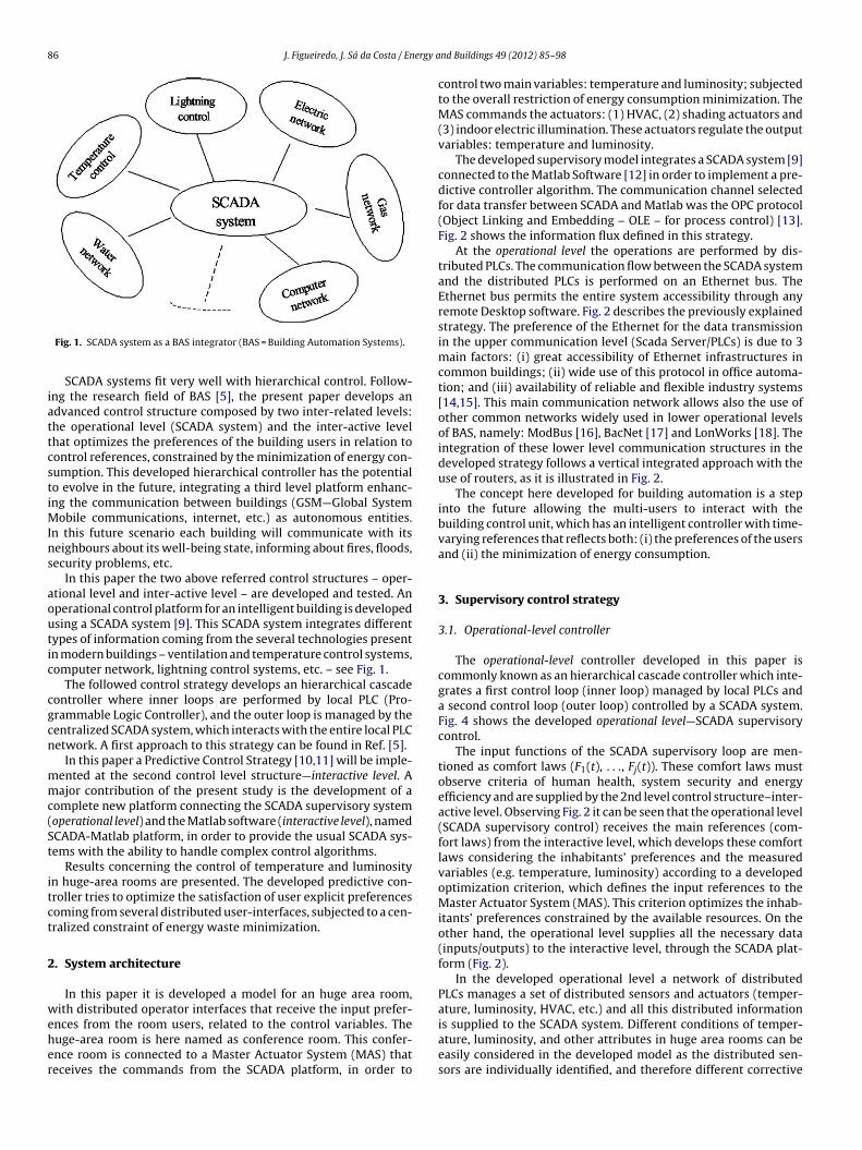
86 J. Figueiredo, J. Sá da Costa / Energy a
iattcstiMIns
aoutic
cgcn
mmc(St
itct
2
weher
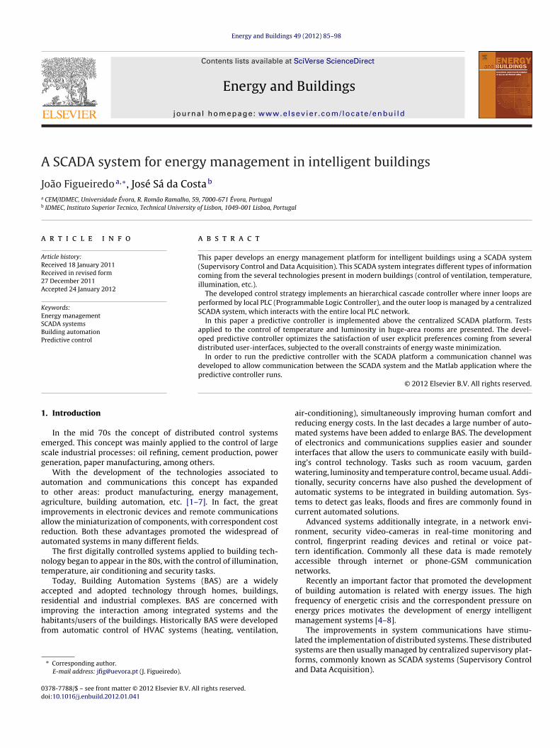
Fig. 1. SCADA system as a BAS integrator (BAS = Building Automation Systems).
SCADA systems fit very well with hierarchical control. Follow-ng the research field of BAS [5], the present paper develops andvanced control structure composed by two inter-related levels:he operational level (SCADA system) and the inter-active levelhat optimizes the preferences of the building users in relation toontrol references, constrained by the minimization of energy con-umption. This developed hierarchical controller has the potentialo evolve in the future, integrating a third level platform enhanc-ng the communication between buildings (GSM—Global System
obile communications, internet, etc.) as autonomous entities.n this future scenario each building will communicate with itseighbours about its well-being state, informing about fires, floods,ecurity problems, etc.
In this paper the two above referred control structures – oper-tional level and inter-active level – are developed and tested. Anperational control platform for an intelligent building is developedsing a SCADA system [9]. This SCADA system integrates differentypes of information coming from the several technologies presentn modern buildings – ventilation and temperature control systems,omputer network, lightning control systems, etc. – see Fig. 1.
The followed control strategy develops an hierarchical cascadeontroller where inner loops are performed by local PLC (Pro-rammable Logic Controller), and the outer loop is managed by theentralized SCADA system, which interacts with the entire local PLCetwork. A first approach to this strategy can be found in Ref. [5].
In this paper a Predictive Control Strategy [10,11] will be imple-ented at the second control level structure—interactive level. Aajor contribution of the present study is the development of a
omplete new platform connecting the SCADA supervisory systemoperational level) and the Matlab software (interactive level), namedCADA-Matlab platform, in order to provide the usual SCADA sys-ems with the ability to handle complex control algorithms.
Results concerning the control of temperature and luminosityn huge-area rooms are presented. The developed predictive con-roller tries to optimize the satisfaction of user explicit preferencesoming from several distributed user-interfaces, subjected to a cen-ralized constraint of energy waste minimization.
. System architecture
In this paper it is developed a model for an huge area room,ith distributed operator interfaces that receive the input prefer-
nces from the room users, related to the control variables. Theuge-area room is here named as conference room. This confer-nce room is connected to a Master Actuator System (MAS) thateceives the commands from the SCADA platform, in order to
nd Buildings 49 (2012) 85–98
control two main variables: temperature and luminosity; subjectedto the overall restriction of energy consumption minimization. TheMAS commands the actuators: (1) HVAC, (2) shading actuators and(3) indoor electric illumination. These actuators regulate the outputvariables: temperature and luminosity.
The developed supervisory model integrates a SCADA system [9]connected to the Matlab Software [12] in order to implement a pre-dictive controller algorithm. The communication channel selectedfor data transfer between SCADA and Matlab was the OPC protocol(Object Linking and Embedding – OLE – for process control) [13].Fig. 2 shows the information flux defined in this strategy.
At the operational level the operations are performed by dis-tributed PLCs. The communication flow between the SCADA systemand the distributed PLCs is performed on an Ethernet bus. TheEthernet bus permits the entire system accessibility through anyremote Desktop software. Fig. 2 describes the previously explainedstrategy. The preference of the Ethernet for the data transmissionin the upper communication level (Scada Server/PLCs) is due to 3main factors: (i) great accessibility of Ethernet infrastructures incommon buildings; (ii) wide use of this protocol in office automa-tion; and (iii) availability of reliable and flexible industry systems[14,15]. This main communication network allows also the use ofother common networks widely used in lower operational levelsof BAS, namely: ModBus [16], BacNet [17] and LonWorks [18]. Theintegration of these lower level communication structures in thedeveloped strategy follows a vertical integrated approach with theuse of routers, as it is illustrated in Fig. 2.
The concept here developed for building automation is a stepinto the future allowing the multi-users to interact with thebuilding control unit, which has an intelligent controller with time-varying references that reflects both: (i) the preferences of the usersand (ii) the minimization of energy consumption.
3. Supervisory control strategy
3.1. Operational-level controller
The operational-level controller developed in this paper iscommonly known as an hierarchical cascade controller which inte-grates a first control loop (inner loop) managed by local PLCs anda second control loop (outer loop) controlled by a SCADA system.Fig. 4 shows the developed operational level—SCADA supervisorycontrol.
The input functions of the SCADA supervisory loop are men-tioned as comfort laws (F1(t), . . ., Fj(t)). These comfort laws mustobserve criteria of human health, system security and energyefficiency and are supplied by the 2nd level control structure–inter-active level. Observing Fig. 2 it can be seen that the operational level(SCADA supervisory control) receives the main references (com-fort laws) from the interactive level, which develops these comfortlaws considering the inhabitants’ preferences and the measuredvariables (e.g. temperature, luminosity) according to a developedoptimization criterion, which defines the input references to theMaster Actuator System (MAS). This criterion optimizes the inhab-itants’ preferences constrained by the available resources. On theother hand, the operational level supplies all the necessary data(inputs/outputs) to the interactive level, through the SCADA plat-form (Fig. 2).
In the developed operational level a network of distributedPLCs manages a set of distributed sensors and actuators (temper-ature, luminosity, HVAC, etc.) and all this distributed information
is supplied to the SCADA system. Different conditions of temper-ature, luminosity, and other attributes in huge area rooms can beeasily considered in the developed model as the distributed sen-sors are individually identified, and therefore different corrective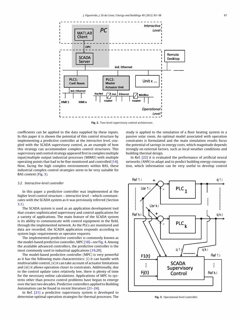
J. Figueiredo, J. Sá da Costa / Energy and Buildings 49 (2012) 85–98 87
rvisor
cIiptsioNiB
3
hc3
taitds
ttm
amatftoA
d
In Ref. [22] it is evaluated the performance of artificial neuralnetworks (ANN) to adapt and to predict building energy consump-tion, which information can be very useful to develop control
Fig. 2. Two-level supe
oefficients can be applied to the data supplied by these inputs.n this paper it is shown the potential of this control structure bymplementing a predictive controller at the interactive level, cou-led with the SCADA supervisory control, as an example of howhis strategy can accommodate complex control structures. Thisupervisory and control strategy appeared first in complex multiplenput/multiple output industrial processes (MIMO) with multipleperating points that had to be fine monitored and controlled [14].ow, facing the high complex environments within BAS, these
ndustrial complex control strategies seem to be very suitable forAS context (Fig. 3).
.2. Interactive-level controller
In this paper a predictive controller was implemented at theigher level control structure – interactive level – which communi-ates with the SCADA system as it was previously referred (Section.1).
The SCADA system is used as an application development toolhat creates sophisticated supervisory and control applications for
variety of applications. The main feature of the SCADA systems its ability to communicate with control equipment in the field,hrough the implemented network. As the PLCs are monitored andata are recorded, the SCADA application responds according toystem logic requirements or operator requests.
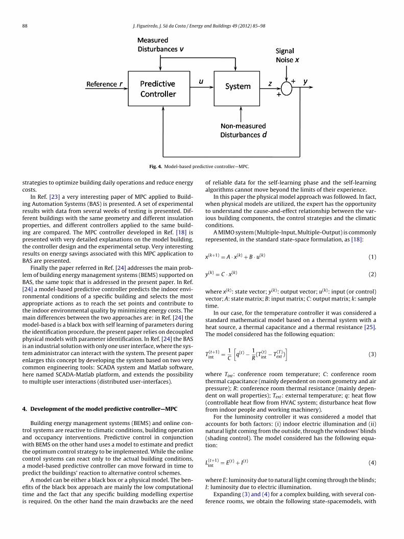
The implemented predictive controller is commonly known ashe model-based predictive controller, MPC [18]—see Fig. 4. Amonghe available advanced controllers, the predictive controller is the
ost commonly used in industrial applications [19,20].The model-based predictive controller (MPC) is very powerful
s it has the following main characteristics: (i) it can handle withultivariable control, (ii) it can take account of actuator limitations
nd (iii) it allows operation closer to constraints. Additionally, dueo the control update rates relatively low, there is plenty of timeor the necessary online calculations. Applications of MPC to sys-ems other than process control problems have begun to emerge
ver the last two decades. Predictive controllers applied to Buildingutomation can be found in recent literature [21–24].In Ref. [21] a predictive supervisory system is developed toetermine optimal operation strategies for thermal processes. The
y control architecture.
study is applied to the simulation of a floor heating system in apassive solar room. An optimal model associated with operationconstraints is formulated and the main simulation results focusthe potential of savings in energy costs, which magnitude dependsstrongly on external factors, such as local weather conditions andbuilding thermal design.
Fig. 3. Operational level controller.
88 J. Figueiredo, J. Sá da Costa / Energy and Buildings 49 (2012) 85–98
redic
sc
irfpiptrB
lB[ratmmtpitecht
4
tawtcap
eti
natural light coming from the outside, through the windows’ blinds(shading control). The model considered has the following equa-tion:
L(t+1)int = E(t) + I(t) (4)
Fig. 4. Model-based p
trategies to optimize building daily operations and reduce energyosts.
In Ref. [23] a very interesting paper of MPC applied to Build-ng Automation Systems (BAS) is presented. A set of experimentalesults with data from several weeks of testing is presented. Dif-erent buildings with the same geometry and different insulationroperties, and different controllers applied to the same build-
ng are compared. The MPC controller developed in Ref. [18] isresented with very detailed explanations on the model building,he controller design and the experimental setup. Very interestingesults on energy savings associated with this MPC application toAS are presented.
Finally the paper referred in Ref. [24] addresses the main prob-em of building energy management systems (BEMS) supported onAS, the same topic that is addressed in the present paper. In Ref.24] a model-based predictive controller predicts the indoor envi-onmental conditions of a specific building and selects the mostppropriate actions as to reach the set points and contribute tohe indoor environmental quality by minimizing energy costs. The
ain differences between the two approaches are: in Ref. [24] theodel-based is a black box with self learning of parameters during
he identification procedure, the present paper relies on decoupledhysical models with parameter identification. In Ref. [24] the BAS
s an industrial solution with only one user interface, where the sys-em administrator can interact with the system. The present papernlarges this concept by developing the system based on two veryommon engineering tools: SCADA system and Matlab software,ere named SCADA-Matlab platform, and extends the possibilityo multiple user interactions (distributed user-interfaces).
. Development of the model predictive controller—MPC
Building energy management systems (BEMS) and online con-rol systems are reactive to climatic conditions, building operationnd occupancy interventions. Predictive control in conjunctionith BEMS on the other hand uses a model to estimate and predict
he optimum control strategy to be implemented. While the onlineontrol systems can react only to the actual building conditions,
model-based predictive controller can move forward in time toredict the buildings’ reaction to alternative control schemes.
A model can be either a black box or a physical model. The ben-fits of the black box approach are mainly the low computationalime and the fact that any specific building modelling expertises required. On the other hand the main drawbacks are the need
tive controller—MPC.
of reliable data for the self-learning phase and the self-learningalgorithms cannot move beyond the limits of their experience.
In this paper the physical model approach was followed. In fact,when physical models are utilized, the expert has the opportunityto understand the cause-and-effect relationship between the var-ious building components, the control strategies and the climaticconditions.
A MIMO system (Multiple-Input, Multiple-Output) is commonlyrepresented, in the standard state-space formulation, as [18]:
x(k+1) = A · x(k) + B · u(k) (1)
y(k) = C · x(k) (2)
where x(k): state vector; y(k): output vector; u(k): input (or control)vector; A: state matrix; B: input matrix; C: output matrix; k: sampletime.
In our case, for the temperature controller it was considered astandard mathematical model based on a thermal system with aheat source, a thermal capacitance and a thermal resistance [25].The model considered has the following equation:
T (t+1)int = 1
C
[q(t) − 1
R(T (t)
int − T (T)ext )
](3)
where Tint: conference room temperature; C: conference roomthermal capacitance (mainly dependent on room geometry and airpressure); R: conference room thermal resistance (mainly depen-dent on wall properties); Text: external temperature; q: heat flow(controllable heat flow from HVAC system; disturbance heat flowfrom indoor people and working machinery).
For the luminosity controller it was considered a model thataccounts for both factors: (i) indoor electric illumination and (ii)
where E: luminosity due to natural light coming through the blinds;I: luminosity due to electric illumination.
Expanding (3) and (4) for a complex building, with several con-ference rooms, we obtain the following state-spacemodels, with

ergy a
t(
⎧⎪⎨⎪⎩
⎧⎪⎨⎪⎩⎧⎪⎨⎪⎩
⎧⎪⎨⎪⎩ls
arttumadnt
Mi
x
y
i
J. Figueiredo, J. Sá da Costa / En
he state equations (5) and (7) and the output equations (6) and8):
T (t+1)int 1
...T (t+1)
int n
⎫⎪⎬⎪⎭ =
⎡⎢⎢⎢⎣
− 1R1 · C1
· · · 0
.... . .
...
0 · · · − 1Rn · Cn
⎤⎥⎥⎥⎦
⎧⎪⎨⎪⎩
T (t)int 1...
T (t)int n
⎫⎪⎬⎪⎭
+
⎡⎢⎢⎢⎣
− 1C1
· · · 01
R1 · C1· · · 0
.... . . · · · · · · . . .
...
0 · · · − 1Cn
0 · · · 1Rn · Cn
⎤⎥⎥⎥⎦
⎧⎪⎪⎪⎪⎪⎪⎪⎪⎨⎪⎪⎪⎪⎪⎪⎪⎪⎩
q(t)1...
q(t)n
T (t)ext 1...
T (t)ext n
⎫⎪⎪⎪⎪⎪⎪⎪⎪⎬⎪⎪⎪⎪⎪⎪⎪⎪⎭
(5)
T (t)int 1...
T (t)int n
⎫⎪⎬⎪⎭ =
⎡⎣ 1 · · · 0
.... . .
...0 · · · 1
⎤⎦ ·
⎧⎪⎨⎪⎩
T (t)int 1...
T (t)int n
⎫⎪⎬⎪⎭ (6)
L(t+1)int 1
...L(t+1)
int n
⎫⎪⎬⎪⎭ =
⎡⎣ 0 · · · 0
.... . .
...0 · · · 0
⎤⎦ .
⎧⎪⎨⎪⎩
L(t)int 1...
L(t)int n
⎫⎪⎬⎪⎭
+
⎡⎣ 1 · · · 0 1 · · · 0
.... . .
......
. . ....
0 · · · 1 0 · · · 1
⎤⎦ .
⎛⎜⎜⎜⎜⎜⎜⎜⎜⎝
E(t)1...
E(t)n
I(t)1...
I(t)n
⎞⎟⎟⎟⎟⎟⎟⎟⎟⎠
(7)
L(t)int 1...
L(t)int n
⎫⎪⎬⎪⎭ =
⎡⎣ 1 · · · 0
.... . .
...0 · · · 1
⎤⎦ ·
⎧⎪⎨⎪⎩
L(t)int 1...
L(t)int n
⎫⎪⎬⎪⎭ (8)
Adopting this model for the specific control of temperature anduminosity of huge-area rooms (conference centres, theatres, etc.)ome physical aspects have to be taken into account.
The model built in Eq. (5) refers mainly to huge-area rooms, asbove referred. In this case the intrinsic thermal properties of eachoom and the room’s connection to the external temperature arehe dominant effects in the heat flux of the modelled room. Theemperature difference related to other adjacent rooms, especiallynder the consideration of good insulation properties of the com-on walls is of relative small effect. This approximation leads to
mathematical model of multiple independent rooms, with theirect consequence of the state matrix [A] with zero elements in allon-diagonal positions. This is exactly the case considered here forhe further developments, as it will be later explained.
Considering the previously presented space state equations for aIMO system, Eqs. (1) and (2), they can be rewritten with separate
nputs (controllable variables and disturbances):
(k+1) = A · x(k) + B1 · u(k)control + B2 · u(k)
disturbances (9)
(k) = C · x(k) (10)
Following this format, Eqs. (5)–(7) and (6)–(8) are aggregatedn order to obtain the complete dynamical model for temperature
nd Buildings 49 (2012) 85–98 89
and luminosity control, as follows:
{T (t+1)
int 1L(t+1)
int 1
}=
[− 1
R1 · C10
0 0
]·{
T (t)int 1
L(t)int 1
}+
[− 1
C10 0
0 1 1
]·
⎧⎨⎩
q(t)1
E(t)1
I(t)1
⎫⎬⎭
+[
1R1 · C1
0
]· T (t)
ext 1 (11)
{T (t)
int 1L(t)
int 1
}=
[1 00 1
]·{
T (t)int 1
L(t)int 1
}(12)
where R1 = d/(A · k) = 0.01 ◦C/W; d: wall thickness (m); A:wall cross-section (m2); k: wall material thermal conductivity(W/(m ◦C)); C1 = Cp · � · V = 581, 292 J/◦C; Cp: air specific heat(J/(kg ◦C)); �: air density (kg/m3); V: conference room volume (m3).
As it was previously referred, the developed models for tem-perature control (Eq. (3)) and luminosity control (Eq. (4)) arecompletely decoupled in terms of variables. This was intentionallydone in order to show the robustness of the developed hierarchicalcontroller even when simple reference models are considered. Infact the MPC controller needs very small expertise in model build-ing to deliver good tracking results. In the present case, the shortwave flux, which couples both Eqs. (3) and (4), in more complexmodels, was not considered and the MPC is able to deliver verygood tracking trajectories (see Section 5.2).
Additionally this supervisory model allows the considerationof simultaneous different references coming from different user-interfaces that have to be combined, according to an optimizationcriterion, in order to supply single coherent references to local PLCs.
Finally, the control strategy here developed considers the com-fort inputs Refj·i (illustrated in Fig. 3) as references to be followedas a typical tracking problem. However recent works [23] showadvantage in defining slack variables in order to keep room tem-peratures above the reference (in case of heating). In the developedstrategy the consideration of additional slack variables can be easilyaccommodated in the SCADA platform, named SCADA supervisoryin Fig. 3.
4.1. Parameter identification
The complete model developed for Room 1, referred in Eqs. (11)and (12) consider the following variables:
- State variables: Tint, Lint, respectively indoor temperature andluminosity;
- Controllable inputs: q1, E1, L1, respectively controllable heat flowfrom HVAC, luminosity due to natural light coming through theblinds (shading control), luminosity due to electric illumination;
- Measured perturbations: Text 1, external temperature in theneighbourhood of Room 1;
- Output variables: Tint, Lint (identical to the state variables in thismodel).
Knowing the critical role of model parameter identification onthe performance of a MPC—model predictive controller, some con-siderations are addressed below.
Relatively to the temperature controller model (Eq. (3)) theexperimental identification of the model parameters C and R is asimple practice that requires a standard instrumentation packagecomposed of a controllable heat flow source and a set of temper-
ature sensors, whose number depends on the area and geometriccharacteristics of the room in evaluation. The experimentation hasto be conducted for a sufficient time interval for each differentmagnitude of the supplied heat flow, until the steady-state indoor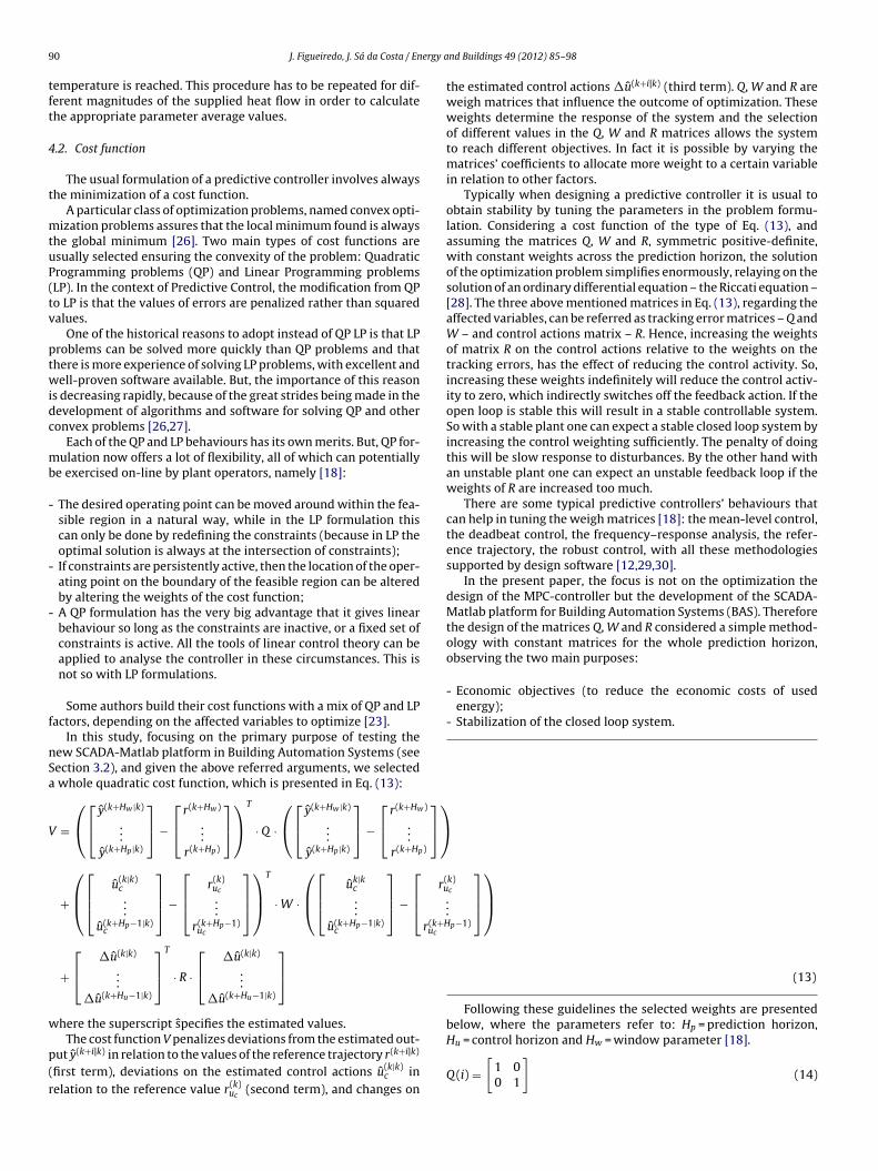
9 ergy a
tft
4
t
mtuP(tv
ptwidc
mb
-
-
-
f
nSa
V
)
)
⎤⎦
⎞⎠
r(u
r(k+Huc
w
p(r
0 J. Figueiredo, J. Sá da Costa / En
emperature is reached. This procedure has to be repeated for dif-erent magnitudes of the supplied heat flow in order to calculatehe appropriate parameter average values.
.2. Cost function
The usual formulation of a predictive controller involves alwayshe minimization of a cost function.
A particular class of optimization problems, named convex opti-ization problems assures that the local minimum found is always
he global minimum [26]. Two main types of cost functions aresually selected ensuring the convexity of the problem: Quadraticrogramming problems (QP) and Linear Programming problemsLP). In the context of Predictive Control, the modification from QPo LP is that the values of errors are penalized rather than squaredalues.
One of the historical reasons to adopt instead of QP LP is that LProblems can be solved more quickly than QP problems and thathere is more experience of solving LP problems, with excellent andell-proven software available. But, the importance of this reason
s decreasing rapidly, because of the great strides being made in theevelopment of algorithms and software for solving QP and otheronvex problems [26,27].
Each of the QP and LP behaviours has its own merits. But, QP for-ulation now offers a lot of flexibility, all of which can potentially
e exercised on-line by plant operators, namely [18]:
The desired operating point can be moved around within the fea-sible region in a natural way, while in the LP formulation thiscan only be done by redefining the constraints (because in LP theoptimal solution is always at the intersection of constraints);
If constraints are persistently active, then the location of the oper-ating point on the boundary of the feasible region can be alteredby altering the weights of the cost function;
A QP formulation has the very big advantage that it gives linearbehaviour so long as the constraints are inactive, or a fixed set ofconstraints is active. All the tools of linear control theory can beapplied to analyse the controller in these circumstances. This isnot so with LP formulations.
Some authors build their cost functions with a mix of QP and LPactors, depending on the affected variables to optimize [23].
In this study, focusing on the primary purpose of testing theew SCADA-Matlab platform in Building Automation Systems (seeection 3.2), and given the above referred arguments, we selected
whole quadratic cost function, which is presented in Eq. (13):
=
⎛⎝
⎡⎣ y(k+Hw |k)
...y(k+Hp|k)
⎤⎦ −
⎡⎣ r(k+Hw)
...r(k+Hp)
⎤⎦
⎞⎠
T
· Q ·
⎛⎝
⎡⎣ y(k+Hw |k)
...y(k+Hp|k)
⎤⎦ −
⎡⎣ r(k+Hw
...r(k+Hp
+
⎛⎜⎝
⎡⎢⎣ u(k|k)
c...
u(k+Hp−1|k)c
⎤⎥⎦ −
⎡⎢⎣ r(k)
uc
...r(k+Hp−1)uc
⎤⎥⎦
⎞⎟⎠
T
· W ·
⎛⎜⎝
⎡⎢⎣ uk|k
c...
u(k+Hp−1|k)c
⎤⎥⎦ −
⎡⎢⎣
+
⎡⎣ �u(k|k)
...�u(k+Hu−1|k)
⎤⎦
T
· R ·
⎡⎣ �u(k|k)
...�u(k+Hu−1|k)
⎤⎦
here the superscript specifies the estimated values.
The cost function V penalizes deviations from the estimated out-ut y(k+i|k) in relation to the values of the reference trajectory r(k+i|k)
first term), deviations on the estimated control actions u(k|k)c in
elation to the reference value r(k)uc
(second term), and changes on
nd Buildings 49 (2012) 85–98
k)c
...p−1)
⎤⎥⎦
⎞⎟⎠
(13)
the estimated control actions �u(k+i|k) (third term). Q, W and R areweigh matrices that influence the outcome of optimization. Theseweights determine the response of the system and the selectionof different values in the Q, W and R matrices allows the systemto reach different objectives. In fact it is possible by varying thematrices’ coefficients to allocate more weight to a certain variablein relation to other factors.
Typically when designing a predictive controller it is usual toobtain stability by tuning the parameters in the problem formu-lation. Considering a cost function of the type of Eq. (13), andassuming the matrices Q, W and R, symmetric positive-definite,with constant weights across the prediction horizon, the solutionof the optimization problem simplifies enormously, relaying on thesolution of an ordinary differential equation – the Riccati equation –[28]. The three above mentioned matrices in Eq. (13), regarding theaffected variables, can be referred as tracking error matrices – Q andW – and control actions matrix – R. Hence, increasing the weightsof matrix R on the control actions relative to the weights on thetracking errors, has the effect of reducing the control activity. So,increasing these weights indefinitely will reduce the control activ-ity to zero, which indirectly switches off the feedback action. If theopen loop is stable this will result in a stable controllable system.So with a stable plant one can expect a stable closed loop system byincreasing the control weighting sufficiently. The penalty of doingthis will be slow response to disturbances. By the other hand withan unstable plant one can expect an unstable feedback loop if theweights of R are increased too much.
There are some typical predictive controllers’ behaviours thatcan help in tuning the weigh matrices [18]: the mean-level control,the deadbeat control, the frequency–response analysis, the refer-ence trajectory, the robust control, with all these methodologiessupported by design software [12,29,30].
In the present paper, the focus is not on the optimization thedesign of the MPC-controller but the development of the SCADA-Matlab platform for Building Automation Systems (BAS). Thereforethe design of the matrices Q, W and R considered a simple method-ology with constant matrices for the whole prediction horizon,observing the two main purposes:
- Economic objectives (to reduce the economic costs of usedenergy);
- Stabilization of the closed loop system.
Following these guidelines the selected weights are presentedbelow, where the parameters refer to: Hp = prediction horizon,
Hu = control horizon and Hw = window parameter [18].Q (i) =[
1 00 1
](14)
ergy a
w
W
w
R
w
wg
(tinsr
J. Figueiredo, J. Sá da Costa / En
here i = [Hw; Hp]
(i) =[
0.001 0 00 0 00 0 75
](15)
here i = [0; Hp − 1]
(i) =[
0.001 0 00 0.1 00 0 5
](16)
here i = [0; Hu − 1].As it can be seen in the selected coefficients, the largest penalty
as attributed to the electric illumination. Therefore preference isiven to natural illumination coming through the blinds.
The largest penalty associated with electric illuminationweights 75 and 5 in matrices W and R, respectively) comparedo penalty associated with natural illumination (weights 0 and 0.1
n matrices W and R, respectively) reflects the clear preference foratural light. However, also this light is associated with energy con-umption due to the blinds’ motorization. This energy cost is hereeflected with a small penalty different from zero.Fig. 5. Developed MPC-controller ov
Fig. 6. Model for H
nd Buildings 49 (2012) 85–98 91
The minimization of energy consumption is here indirectly con-sidered by the design of the weigh matrices.
4.3. Constraints of the cost function
In this study, the optimization of the cost function is constrainedby the allowable amplitudes of both the input variables (Eq. (11))and the outputs (Eq. (12)). Usually these constraint are representedby a set of equations [18]:⎡⎢⎢⎢⎢⎢⎢⎢⎢⎢⎢⎣
yHamin· · ·
yHpmin
u0cmin· · ·
uHp−1cmin
�u0cmin
· · ·
⎤⎥⎥⎥⎥⎥⎥⎥⎥⎥⎥⎦
≤
⎡⎢⎢⎢⎢⎢⎢⎢⎢⎢⎣
yHa
· · ·yHp
u0c
· · ·uHp−1
c�u0
c· · ·
⎤⎥⎥⎥⎥⎥⎥⎥⎥⎥⎦
≤
⎡⎢⎢⎢⎢⎢⎢⎢⎢⎢⎣
yHamax· · ·
yHpmax
u0cmax· · ·
uHp−1cmax
�u0cmax
· · ·
⎤⎥⎥⎥⎥⎥⎥⎥⎥⎥⎦
(17)
�uHp−1cmin
�uHp−1c �uHp−1
cmax
Considering first the output variables (inside temperature andluminosity—Eq. (12)), it was assumed no constraint for the inside
erview—Matlab platform [12].
VAC Unit 1.
9 ergy a
ta
tain(oFs
5
artcdcfs
ttttw
LtttfoCp
2 J. Figueiredo, J. Sá da Costa / En
emperature and it was assumed for the luminosity, that this vari-ble cannot be negative.
Now considering the constraints on the input variables, we haveo analyse the constraints on the allowable amplitudes and vari-tions. In the present study there are two types of controllablenputs: inputs produced artificially (heat flow from HVAC, lumi-osity from electric illumination) and inputs produced naturallyluminosity from natural light). For the first class of inputs theirperational constraints are defined by the equipment producers.or the second class of inputs, the maximal allowable value corre-ponds to an overture of 100% of the blinds).
. Results
The results presented in this chapter aim to demonstrate thebility of the developed controller strategy to reach the proposedeferences. The supervisory controller developed in Section 3 wasested. In Fig. 5 it is shown an overview of the implementedontroller, running in the Matlab Simulink software [12]. This pre-ictive controller manages the temperature and luminosity of oneonference room, according to user explicit preferences comingrom distributed user-interfaces and subjected to the main con-traint of energy consumption minimization.
This predictive controller could not be implemented directly onhe SCADA system because this system does not have the capacityo deal with complex mathematical operations requested by thisype of controller. So it was necessary to develop a communica-ion channel between the SCADA [9] and the Matlab software [12],here the predictive controller was implemented.
The used communication channel is the OPC protocol (Objectinking and Embedding – OLE– for process control) [13]. This pro-ocol is based on standard specifications developed in 1996 by aask force from industrial automation [31]. This standard specifieshe communication of real-time data among several control devices
rom different manufacturers. This protocol provides the exchangef data between two independent software programs (Server andlient), running simultaneous at the implemented platform. In thisaper the Matlab software initiates the communication, as it is theFig. 7. Model for Lum
nd Buildings 49 (2012) 85–98
Client and the SCADA software responds to Client’s requests (Serverattributions) [13,31].
Two different types of results are shown in this section: simu-lation and experimental tests.
5.1. Simulation results
In the simulation tests, performed for Conference Room 1, thefollowing conditions were considered:
- Simulation interval = 1 h;- User-defined temperatures are randomly generated, in the range
20–30 ◦C, each 10 min;- User-defined luminosities are randomly generated, in the range
20–30 ◦C, each 10 min;- Exterior temperature = 24 ◦C;- Exterior luminosity = 100% (correspondent to clear sky).
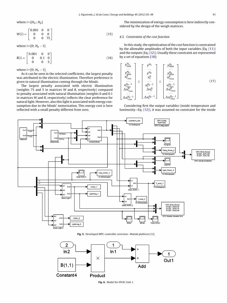
The simulation results were obtained with the Matlab software[12]. The resolution of the overall model previously presented inFig. 6, considered the following partial models: HVAC Unit 1 (Fig. 6);Luminosity Unit 1 (Fig. 7); Control Block (Fig. 8) and Reference Block(Fig. 9).
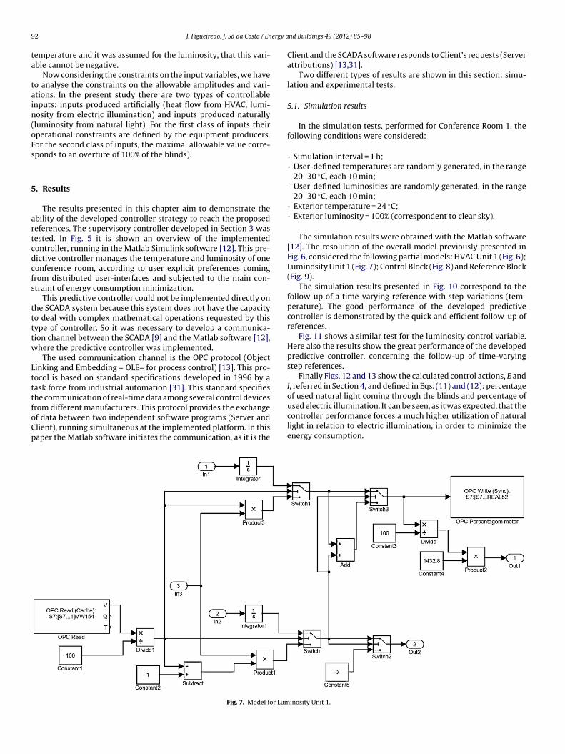
The simulation results presented in Fig. 10 correspond to thefollow-up of a time-varying reference with step-variations (tem-perature). The good performance of the developed predictivecontroller is demonstrated by the quick and efficient follow-up ofreferences.
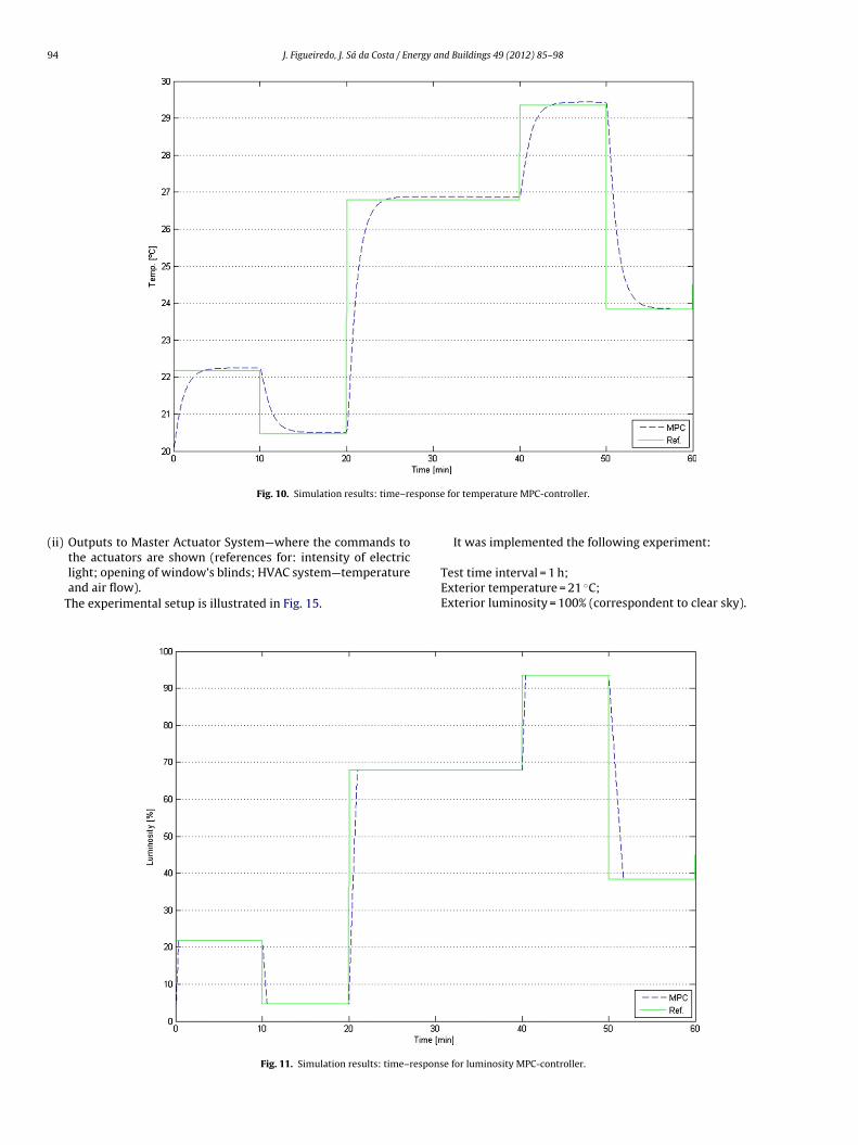
Fig. 11 shows a similar test for the luminosity control variable.Here also the results show the great performance of the developedpredictive controller, concerning the follow-up of time-varyingstep references.
Finally Figs. 12 and 13 show the calculated control actions, E andI, referred in Section 4, and defined in Eqs. (11) and (12): percentageof used natural light coming through the blinds and percentage of
used electric illumination. It can be seen, as it was expected, that thecontroller performance forces a much higher utilization of naturallight in relation to electric illumination, in order to minimize theenergy consumption.inosity Unit 1.

J. Figueiredo, J. Sá da Costa / Energy a
5
vntc
Fig. 8. Model for Control Block.
.2. Experimental results
The main purpose of the experimental tests was to evaluate the
iability of the proposed strategy, namely the failure free commu-ication between the SCADA supervisory system, the PLC network,he update of the user-defined variables and the correspondentalculated references, according to the MPC algorithm.Fig. 9. Model for Re
nd Buildings 49 (2012) 85–98 93
Additionally, the developed tests prove the capacity of theproposed strategy to manage different levels of decision and themanagement of multiple simultaneous user-reference data.
The tested prototype is composed by:
- 2 physical user-interfaces connected by ProfiBus network withProgrammable Logic Controllers 1 and 2 (PLC1 and PLC2);
- PLC1 is connected by Ethernet with the SCADA server;- PLC2 is connected by Ethernet with the SCADA server.
The actuators controlled by the PLC2 – Master Actuator System– were simulated by Matlab because the installation did not havein place the systems: HVAC, shading control and indoor illumina-tion. These actuators were modelled by linear devices with theirslope dependent on the magnitude of the given reference. Addi-tionally, due to the availability of only two physical user-interfaces,the data referred to the other user-defined references were directlyintroduced in the SCADA Graphical User Interface (GUI).
Fig. 14 presents the main Graphical User Interface developed forthe SCADA platform. This menu informs the system administratorabout how many users are communicating with the managementsystem, the actual values of temperature and luminosity, and the
mean values of the users’ preferences.Additional menus are accessible to the system administrator:(i) Inputs from Conf. Room—where the users’ preferences are mon-
itored;
ference Block.
94 J. Figueiredo, J. Sá da Costa / Energy and Buildings 49 (2012) 85–98
spons
(
Fig. 10. Simulation results: time–re
ii) Outputs to Master Actuator System—where the commands to
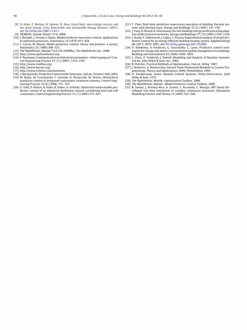
the actuators are shown (references for: intensity of electriclight; opening of window’s blinds; HVAC system—temperatureand air flow).The experimental setup is illustrated in Fig. 15.
Fig. 11. Simulation results: time–respon
e for temperature MPC-controller.
It was implemented the following experiment:
Test time interval = 1 h;Exterior temperature = 21 ◦C;Exterior luminosity = 100% (correspondent to clear sky).
se for luminosity MPC-controller.

J. Figueiredo, J. Sá da Costa / Energy and Buildings 49 (2012) 85–98 95
Fig. 12. Simulation results: utilization of natural light.
Fig. 13. Simulation results: uti
lization of electric light.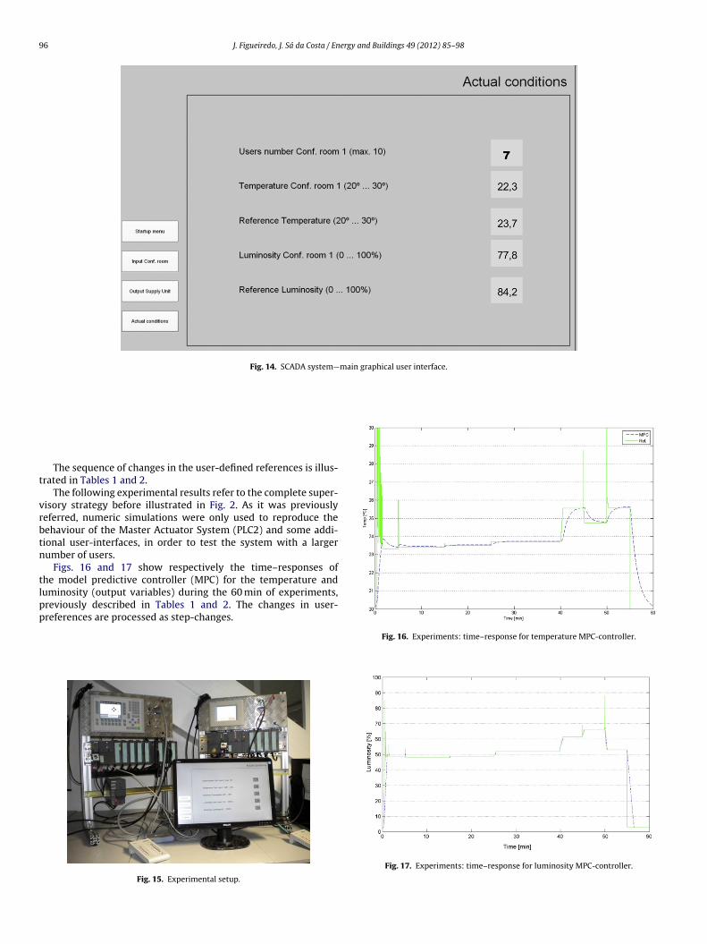
96 J. Figueiredo, J. Sá da Costa / Energy and Buildings 49 (2012) 85–98
Fig. 14. SCADA system—main graphical user interface.
t
vrbtn
tlpp
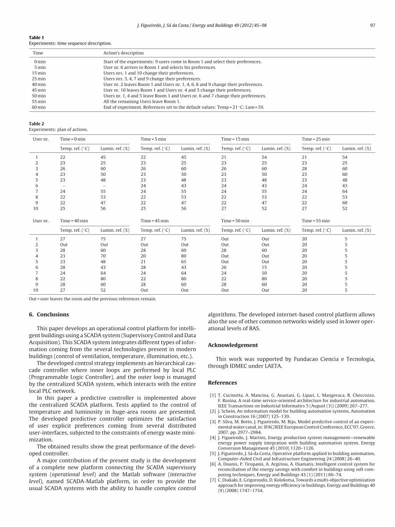
The sequence of changes in the user-defined references is illus-rated in Tables 1 and 2.
The following experimental results refer to the complete super-isory strategy before illustrated in Fig. 2. As it was previouslyeferred, numeric simulations were only used to reproduce theehaviour of the Master Actuator System (PLC2) and some addi-ional user-interfaces, in order to test the system with a largerumber of users.
Figs. 16 and 17 show respectively the time–responses ofhe model predictive controller (MPC) for the temperature anduminosity (output variables) during the 60 min of experiments,reviously described in Tables 1 and 2. The changes in user-
references are processed as step-changes.Fig. 15. Experimental setup.
Fig. 16. Experiments: time–response for temperature MPC-controller.
Fig. 17. Experiments: time–response for luminosity MPC-controller.
J. Figueiredo, J. Sá da Costa / Energy and Buildings 49 (2012) 85–98 97
Table 1Experiments: time sequence description.
Time Action’s description
0 min Start of the experiments: 9 users come in Room 1 and select their preferences.5 min User nr. 6 arrives to Room 1 and selects his preferences.
15 min Users nrs. 1 and 10 change their preferences.25 min Users nrs. 3, 4, 7 and 9 change their preferences.40 min User nr. 2 leaves Room 1 and Users nr. 1, 4, 6, 8 and 9 change their preferences.45 min User nr. 10 leaves Room 1 and Users nr. 4 and 5 change their preferences.50 min Users nr. 1, 4 and 5 leave Room 1 and Users nr. 6 and 7 change their preferences.55 min All the remaining Users leave Room 1.60 min End of experiment. References set to the default values: Temp = 21 ◦C; Lum = 5%
Table 2Experiments: plan of actions.
User nr. Time = 0 min Time = 5 min Time = 15 min Time = 25 min
Temp. ref. (◦C) Lumin. ref. (%) Temp. ref. (◦C) Lumin. ref. (%) Temp. ref. (◦C) Lumin. ref. (%) Temp. ref. (◦C) Lumin. ref. (%)
1 22 45 22 45 21 54 21 542 23 25 23 25 23 25 23 253 26 60 26 60 26 60 28 604 23 50 23 50 23 50 23 605 23 48 23 48 23 48 23 486 – – 24 43 24 43 24 437 24 55 24 55 24 55 24 648 22 53 22 53 22 53 22 539 22 47 22 47 22 47 22 60
10 25 56 25 56 27 52 27 52
User nr. Time = 40 min Time = 45 min Time = 50 min Time = 55 min
Temp. ref. (◦C) Lumin. ref. (%) Temp. ref. (◦C) Lumin. ref. (%) Temp. ref. (◦C) Lumin. ref. (%) Temp. ref. (◦C) Lumin. ref. (%)
1 27 75 27 75 Out Out 20 52 Out Out Out Out Out Out 20 53 28 60 28 60 28 60 20 54 23 70 20 80 Out Out 20 55 23 48 21 65 Out Out 20 56 28 43 28 43 26 15 20 57 24 64 24 64 24 50 20 58 22 80 22 80 22 80 20 59 28 60 28 60 28 60 20 5
O
6
gAmb
c(bl
ttToum
o
oslu
10 27 52 Out Out
ut = user leaves the room and the previous references remain.
. Conclusions
This paper develops an operational control platform for intelli-ent buildings using a SCADA system (Supervisory Control and Datacquisition). This SCADA system integrates different types of infor-ation coming from the several technologies present in modern
uildings (control of ventilation, temperature, illumination, etc.).The developed control strategy implements an hierarchical cas-
ade controller where inner loops are performed by local PLCProgrammable Logic Controller), and the outer loop is managedy the centralized SCADA system, which interacts with the entire
ocal PLC network.In this paper a predictive controller is implemented above
he centralized SCADA platform. Tests applied to the control ofemperature and luminosity in huge-area rooms are presented.he developed predictive controller optimizes the satisfactionf user explicit preferences coming from several distributedser-interfaces, subjected to the constraints of energy waste mini-ization.The obtained results show the great performance of the devel-
ped controller.A major contribution of the present study is the development
f a complete new platform connecting the SCADA supervisoryystem (operational level) and the Matlab software (interactiveevel), named SCADA-Matlab platform, in order to provide thesual SCADA systems with the ability to handle complex control
Out Out 20 5
algorithms. The developed internet-based control platform allowsalso the use of other common networks widely used in lower oper-ational levels of BAS.
Acknowledgement
This work was supported by Fundacao Ciencia e Tecnologia,through IDMEC under LAETA.
References
[1] T. Cucinotta, A. Mancina, G. Anastasi, G. Lipari, L. Mangeruca, R. Checcozzo,F. Rusina, A real-time service-oriented architecture for industrial automation,IEEE Transactions on Industrial Informatics 5 (August (3)) (2009) 267–277.
[2] J. Schein, An information model for building automation systems, Automationin Construction 16 (2007) 125–139.
[3] P. Silva, M. Botto, J. Figueiredo, M. Rijo, Model predictive control of an experi-mental water canal, in: IFAC/IEEE European Control Conference, ECC’07, Greece,2007, pp. 2977–2984.
[4] J. Figueiredo, J. Martins, Energy production system management—renewableenergy power supply integration with building automation system, EnergyConversion Management 45 (2010) 1120–1126.
[5] J. Figueiredo, J. Sá da Costa, Operative platform applied to building automation,Computer-Aided Civil and Infrastructure Engineering 24 (2008) 26–40.
[6] A. Dounis, P. Tiropanis, A. Argiriou, A. Diamatis, Intelligent control system for
reconciliation of the energy savings with comfort in buildings using soft com-puting techniques, Energy and Buildings 43 (1) (2011) 66–74.[7] C. Diakaki, E. Grigoroudis, D. Kolokotsa, Towards a multi-objective optimizationapproach for improving energy efficiency in buildings, Energy and Buildings 40(9) (2008) 1747–1754.
9 ergy a
[
[
[[[
[[[[[
[
[
[
[
[
[
[[
[
8 J. Figueiredo, J. Sá da Costa / En
[8] N. Khan, Z. Mariun, N. Saleem, N. Abas, Fossil fuels, new energy sources andthe great energy crisis, Renewable and Sustainable Energy Reviews (2007),doi:10.1016/j.rser.2007.11.011.
[9] SIEMENS, Simatic WinCC V7.0, 2008.10] J. Richalet, J. Testud, J. Papon, Model predictive heuristics control: applications
to industrial processes, Automatica 14 (1978) 413–428.11] C. Garcia, M. Morari, Model predictive control: theory and practice: a survey,
Automatica 25 (1989) 308–323.12] The MathWorks, Matlab 7.6.0.324 (R2008a), The MathWorks Inc., 2008.13] http://www.opcfoundation.org.14] P. Neumann, Communication on Industrial automation—what is going on? Con-
trol Engineering Practice 15 (11) (2007) 1332–1347.15] http://www.modbus.org/.16] http://www.bacnet.org/.17] http://www.echelon.com/lonworks.18] J. Maciejowski, Predictive Control with Constrains, 2nd ed., Prentice-Hall, 2002.19] M. Brdys, M. Grochowski, T. Gminski, K. Konarczak, M. Drewa, Hierarchical
predictive control of integrated wastewater treatment systems, Control Engi-neering Practice 16 (6) (2008) 751–767.
20] U. Volk, D. Kniese, R. Hahn, R. Haber, U. Schmitz, Optimized multivariable pre-dictive control of an industrial distillation column considering hard and softconstraints, Control Engineering Practice 13 (7) (2005) 913–927.
[[[
nd Buildings 49 (2012) 85–98
21] T. Chen, Real-time predictive supervisory operation of building thermal sys-tems with thermal mass, Energy and Buildings 33 (2) (2001) 141–150.
22] J. Yang, H. Rivard, R. Zmeureanu, On-line building energy prediction using adap-tive artificial neural networks, Energy and Buildings 37 (12) (2005) 1250–1259.
23] J. Siroky, F. Oldewurtel, J. Cigler, S. Privara, Experimental analysis of model pre-dictive control for an energy efficient building heating system, Applied Energy88 (2011) 3079–3087, doi:10.1016/j.apenergy.2011.03.009.
24] D. Kolokotsa, A. Pouliezos, G. Stavrakakis, C. Lazos, Predictive control tech-niques for energy and indoor environmental quality management in buildings,Building and Environment 44 (2009) 1850–1863.
25] C. Close, D. Frederick, J. Newell, Modelling and Analysis of Dynamic Systems,3rd ed., John Wiley & Sons, Inc., 2002.
26] R. Fletcher, Practical Methods of Optimization, 2nd ed., Wiley, 1987.27] J. Nesterov, A. Nemirovsky, Interior Point Polynomial Methods in Convex Pro-
gramming: Theory and Applications, SIAM, Philadelphia, 1994.28] H. Kwakernaak, Linear Optimal Control Systems, Wiley-Interscience, John
Wiley & Sons, 1972.
29] The MathWorks, Matlab—Optimization Toolbox, 2008.30] The MathWorks, Matlab—Model Predictive Control Toolbox, 2008.31] R. Santos, J. Normey-Rico, A. Gomez, L. Arconada, C. Moraga, OPC based dis-tributed real time simulation of complex continuous processes, SimulationModelling Practice and Theory 13 (2005) 525–549.