encryption on the air: non-invasive security for...
TRANSCRIPT
Encryption on the Air: Non-Invasive
Security for Implantable Medical Devices
by
Haitham Al-Hassanieh
Submitted to the Department of Electrical Engineering and Computer Science
in partial fulfillment of the requirements for the degree of
Master of Science in Computer Science and Engineering
at the
MASSACHUSETTS INSTITUTE OF TECHNOLOGY
June 2011
c© Massachusetts Institute of Technology 2011. All rights reserved.
Author . . . . . . . . . . . . . . . . . . . . . . . . . . . . . . . . . . . . . . . . . . . . . . . . . . . . . . . . . . . . . .Department of Electrical Engineering and Computer Science
May 20, 2011
Certified by. . . . . . . . . . . . . . . . . . . . . . . . . . . . . . . . . . . . . . . . . . . . . . . . . . . . . . . . . .Dina Katabi
Associate Professor of Computer Science and EngineeringThesis Supervisor
Accepted by . . . . . . . . . . . . . . . . . . . . . . . . . . . . . . . . . . . . . . . . . . . . . . . . . . . . . . . . .Leslie A. Kolodziejski
Chairman, Department Committee on Graduate Students

2
Encryption on the Air: Non-Invasive Security for
Implantable Medical Devices
by
Haitham Al-Hassanieh
Submitted to the Department of Electrical Engineering and Computer Scienceon May 20, 2011, in partial fulfillment of the
requirements for the degree ofMaster of Science in Computer Science and Engineering
Abstract
Modern implantable medical devices (IMDs) including pacemakers, cardiac defibrilla-tors and nerve stimulators feature wireless connectivity that enables remote monitor-ing and post-implantation adjustment. However, recent work has demonstrated thatflawed security tempers these medical benefits. In particular, an understandable lackof cryptographic mechanisms results in the IMD disclosing private data and beingunable to distinguish authorized from unauthorized commands.
In this thesis, we present IMD-Shield; a prototype defenses against a previouslyproposed suite of attacks on IMDs. IMD-Shield is an external entity that uses a newfull dulpex radio design to secure transmissions to and from the IMD on the airwihtout incorporating the IMD itself. Because replacing the install base of wireless-enabled IMDs is infeasible, our system non-invasively enhances the security of un-modified IMDs. We implement and evaluate our mechanism against modern IMDs ina variety of attack scenarios and find that it effectively provides confidentiality forprivate data and shields the IMD from unauthorized commands.
Thesis Supervisor: Dina KatabiTitle: Associate Professor of Computer Science and Engineering
3

4
Disclaimer
None of the experiments in this thesis were performed on Humans.
The work in this thesis was done in collaboration with another student Shyamnath
Gollakota. Most of the protocols in this thesis were developed during our discussions
and brainstorming sessions. We both share credit for the design and system archi-
tecture. My responsibility extended beyond the design to the realization of our full-
duplex radio on software radios and the empirical study of the IMDs communication
and the effectiveness of the shield in protecting them.
5

6

Acknowledgments
I am really fortunate to have Dina as my adviser. I have never seen someone so
hard working and so passionate about their research. It is truly inspiring. She is
continuously guiding me, advising me and making sure I am on the right track. She
puts the success of her students as her top priority and she goes out of her way to
make sure they’re comfortable. I learned so much from her and I look forward to learn
more in the future.
Many thanks to Dina and Shyam for coming up with such a great research problem
and sharing it with me. I would also like to thank Prof. Kevin Fu for supplying us
with the IMDs used in this thesis.
I am grateful to have Shyam, Rahul, Nate, Jue, Szymon, Swarun and Nabeel as my
group members. I would like to thank Rahul for guiding me through my first project
at MIT and teaching me a lot about wireless. Special thanks to Nate for reviewing
the proposal and the paper of this project multiple times.
I cannot express sufficient gratitude for my parents Najwa and Zuhair and my
siblings Dima and Mazen for their endless love, support and advice. I could not have
achieved what I did without their help and I owe all my success to them. I am also
very grateful to Maha, Nadima, Nahla, Rima, Nawal and Mona; their wisdom, their
strength and their grace have inspired me to be a much better person.
Finally, I am very grateful for my best friends Ali, Hiba, Sarah, Sobhi, Lena, Lina,
Ahmad, Hassane, Majd, Amer, Kassem, Jessica and Pam who are always there for
me and help me get through anything. I can always lean on them and they all make
my life so beautiful.
7

8
Contents
1 Introduction 15
1.1 Current Security of Wireless IMDs . . . . . . . . . . . . . . . . . . . 15
1.2 Non-Invasive Security for Wireless IMDs . . . . . . . . . . . . . . . . 16
1.3 Evaluation of the IMD-Shield . . . . . . . . . . . . . . . . . . . . . . 18
2 Related Work 21
2.1 Security of Implantable Medical Devices . . . . . . . . . . . . . . . . 21
2.2 Physical-Layer Wireless Security . . . . . . . . . . . . . . . . . . . . . 22
2.3 Full-Duplex Wireless Radios . . . . . . . . . . . . . . . . . . . . . . . 23
3 IMD Communication Primer 25
4 Assumptions and Threat Model 27
4.1 Assumptions . . . . . . . . . . . . . . . . . . . . . . . . . . . . . . . . 27
4.2 Threat Model . . . . . . . . . . . . . . . . . . . . . . . . . . . . . . . 28
4.2.1 Passive Eavesdropper . . . . . . . . . . . . . . . . . . . . . . . 28
4.2.2 Active Adversary . . . . . . . . . . . . . . . . . . . . . . . . . 29
5 System Overview 31
6 Jammer-Cum-Receiver 35
6.1 Full-Duplex Radio Design . . . . . . . . . . . . . . . . . . . . . . . . 35
6.2 Design Properties . . . . . . . . . . . . . . . . . . . . . . . . . . . . . 37
9
7 Protection from Passive Eavesdroppers 39
7.1 Specifications of Wireless IMD Communication . . . . . . . . . . . . 39
7.2 Algorithm to Counter Passive Eavesdroppers . . . . . . . . . . . . . . 41
7.2.1 Maximizing Jamming Efficiency for a Given Power Budget . . 41
7.2.2 Ensuring Independence of Eavesdropper Location . . . . . . . 43
7.2.3 The SINR Tradeoff Between the Shield and the Adversary . . 44
8 Protection from Active Adversaries 47
8.1 Algorithm to Counter Active Adversaries . . . . . . . . . . . . . . . . 47
8.1.1 Choosing Unique Identifying Sequences . . . . . . . . . . . . . 48
8.1.2 Setting the Threshold bthresh . . . . . . . . . . . . . . . . . . . 48
8.1.3 Customizing for the MICS Band . . . . . . . . . . . . . . . . . 49
8.1.4 Complying with FCC Rules . . . . . . . . . . . . . . . . . . . 49
8.1.5 The Shield’s Battery Life . . . . . . . . . . . . . . . . . . . . . 50
9 Experiment Setup 51
9.1 Implementation . . . . . . . . . . . . . . . . . . . . . . . . . . . . . . 51
9.2 Testing Environment . . . . . . . . . . . . . . . . . . . . . . . . . . . 52
10 Evaluation 55
10.1 Micro-Benchmark Results . . . . . . . . . . . . . . . . . . . . . . . . 57
10.1.1 Antenna Cancellation . . . . . . . . . . . . . . . . . . . . . . . 57
10.1.2 Tradeoffs Between Eavesdropper Error and Shield Error . . . 58
10.1.3 Setting the Jamming Parameters . . . . . . . . . . . . . . . . 60
10.2 Protecting from Passive Adversaries . . . . . . . . . . . . . . . . . . . 62
10.3 Protecting from Active Adversaries . . . . . . . . . . . . . . . . . . . 64
10.3.1 Adversary Using a Commercial IMD Programmer . . . . . . . 64
10.3.2 High-Power Active Adversary . . . . . . . . . . . . . . . . . . 66
10.4 Coexistence . . . . . . . . . . . . . . . . . . . . . . . . . . . . . . . . 68
11 Conclusion 71
10
List of Figures
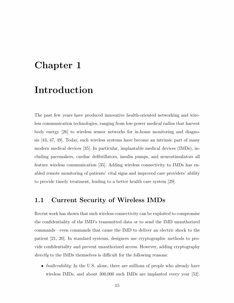
5-1 Framework for protecting a target device without modifying
it: The guard jams any direct communication with the IMD. An au-
thorized programmer communicates with the IMD only through the
Guard over a secure channel. . . . . . . . . . . . . . . . . . . . . . . . 32
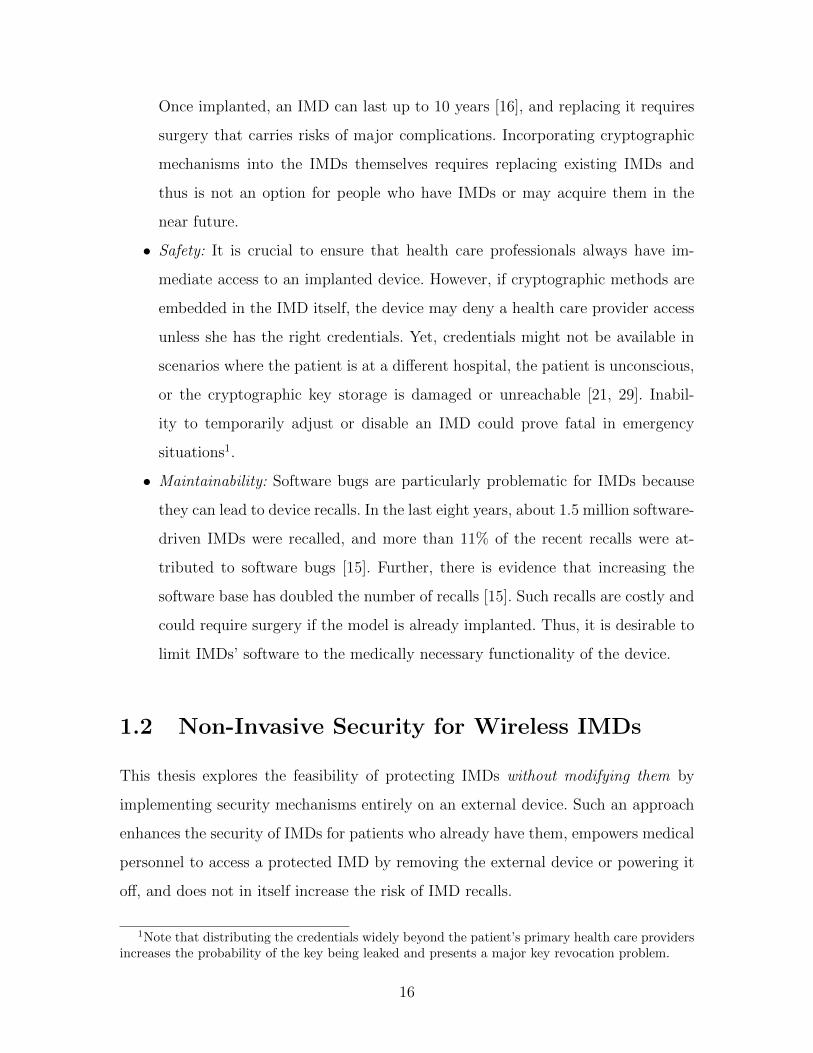
5-2 Demonstration of the shield’s role in protecting the IMD
against active adversaries: (a) In the absence of the shield, the
ICD responds to unauthorized messages. (b) In the presence of the
shield, all unauthorized messages are jammed and the ICD does not
respond to these messages. . . . . . . . . . . . . . . . . . . . . . . . . 33
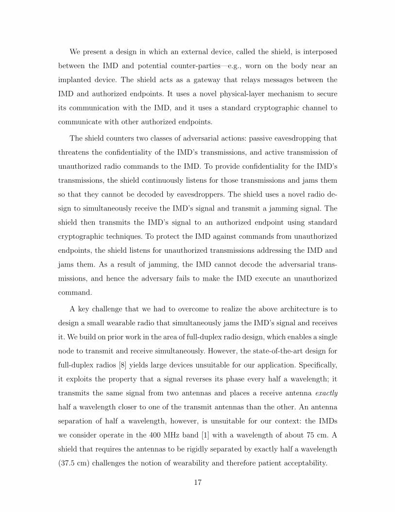
6-1 Jammer-cum-Receiver Design: The design uses 2 antennas: a jam-
ming antenna that transmits the jamming signal and a receive antenna.
The receive antenna is connected to both a transmit and receive chain.
The antidote signal is transmitted from the transmit chain to cancel
out the jamming signal in the receive chain. . . . . . . . . . . . . . . 36
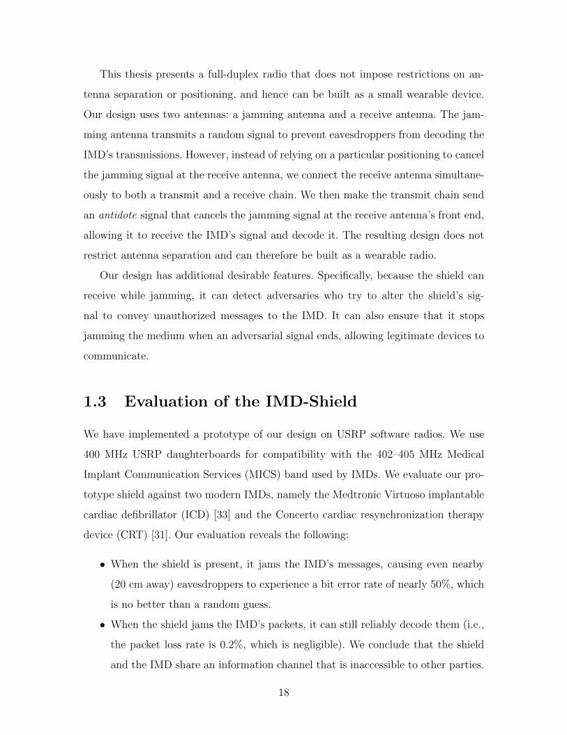
7-1 Typical interaction between the virtuoso IMD and its pro-
grammer: The top graph shows that the IMD transmits in response
to being interrogated. The bottom graph shows that the Virtuoso trans-
mits after a fixed interval without sensing the medium. . . . . . . . . 40
7-2 Frequency profile of IMD signal: The frequency profile of the FSK
signal captured from the Virtuoso cardiac defibrillator shows that most
of the energy is concentrated around ±50 KHz. . . . . . . . . . . . . 42
11
7-3 Shaping the profile of the jamming signal: The frequency profile
of the jamming signal is shaped to match that of the IMD allows the
shield to focus its jamming power on the frequencies that matter for
decoding, as opposed to jamming across the entire 300 KHz channel.
Note: The IMD’s power profile in blue is scaled up for clarity. . . . . 42
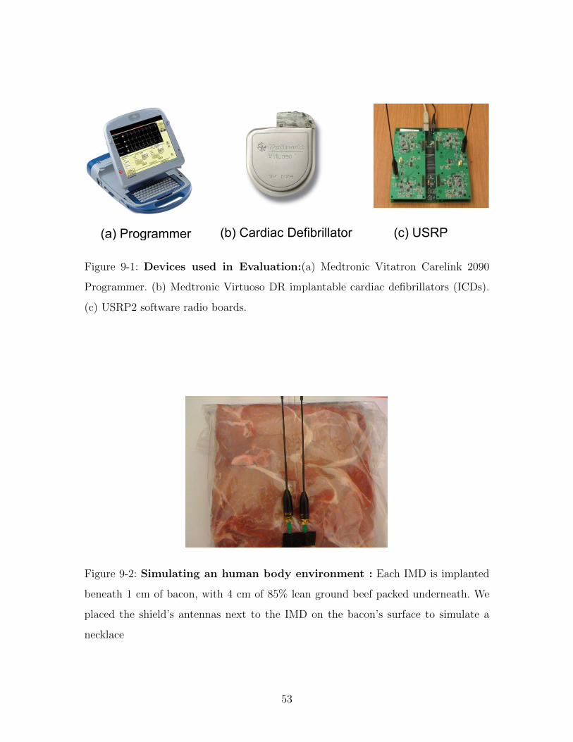
9-1 Devices used in Evaluation:(a) Medtronic Vitatron Carelink 2090
Programmer. (b) Medtronic Virtuoso DR implantable cardiac defibril-
lators (ICDs). (c) USRP2 software radio boards. . . . . . . . . . . . . 53
9-2 Simulating an human body environment : Each IMD is implanted
beneath 1 cm of bacon, with 4 cm of 85% lean ground beef packed
underneath. We placed the shield’s antennas next to the IMD on the
bacon’s surface to simulate a necklace . . . . . . . . . . . . . . . . . . 53
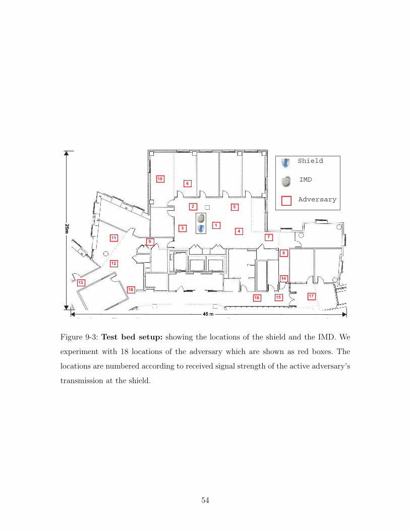
9-3 Test bed setup: showing the locations of the shield and the IMD.
We experiment with 18 locations of the adversary which are shown
as red boxes. The locations are numbered according to received signal
strength of the active adversary’s transmission at the shield. . . . . . 54
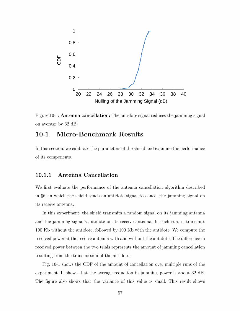
10-1 Antenna cancellation: The antidote signal reduces the jamming sig-
nal on average by 32 dB. . . . . . . . . . . . . . . . . . . . . . . . . . 57
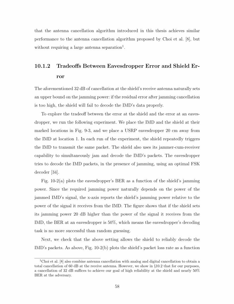
10-2 Tradeoff between BER at the eavesdropper and reliable de-
coding at the shield: The figure shows that if the shield sets its
jamming power 20 dB higher than the power it receives from the IMD,
it can ensure that an eavesdropper sees a BER around 50%—effectively
reducing the eavesdropper to guessing—while keeping the packet loss
rate (PER) at the shield as low as 0.2%. . . . . . . . . . . . . . . . . 59
10-3 BER at the eavesdropper: CDF of an eavesdropper’s BER over all
eavesdropper locations in Fig. 9-3. At all locations, the eavesdropper’s
BER is nearly 50%, which makes its decoding task no more successful
than random guessing. The low variance in the CDF shows that an
eavesdropper’s BER is independent of its location. . . . . . . . . . . . 63
12
10-4 Packet Loss at the shield : When the shield is jamming, it expe-
riences an average packet loss rate of only 0.2% when receiving the
IMD’s packets. We conclude that the shield can reliably decode the
IMD’s transmissions despite jamming. . . . . . . . . . . . . . . . . . 63
10-5 Probability the IMD transmits in reply to an active adversery:
The figure shows that, in the absence of the shield, triggering an IMD
to transmit and deplete its battery using off-the-shelf IMD programmer
succeeds with high probability. In contrast, in the presence of the shield
such attacks fail. . . . . . . . . . . . . . . . . . . . . . . . . . . . . . 65
10-6 Probability the IMD changes therapy in reply to an active
adversary: When the shield is off (absent), an adversary who uses an
off-the-shelf IMD programmer to send unauthorized commands (in this
case, to modify therapy parameters) succeeds with high probability.
When the shield is on (present), it materially decreases the adversary’s
ability to control the IMD. . . . . . . . . . . . . . . . . . . . . . . . . 65
10-7 Probability the IMD changes therapy in reply to a high power
active adversary: When the shield is off (absent), an adversary trans-
mitting at 100 times the shield’s power can change the IMD’s therapy
parameters even from non-line-of-sight locations up to 27 meters away.
However, when the shield is on (present), the adversary is successful
only from line-of-sight locations less than 5 meters away, and the shield
raises an alarm. . . . . . . . . . . . . . . . . . . . . . . . . . . . . . . 67
13

14
Chapter 1
Introduction
The past few years have produced innovative health-oriented networking and wire-
less communication technologies, ranging from low-power medical radios that harvest
body energy [26] to wireless sensor networks for in-home monitoring and diagno-
sis [43, 47, 49]. Today, such wireless systems have become an intrinsic part of many
modern medical devices [35]. In particular, implantable medical devices (IMDs), in-
cluding pacemakers, cardiac defibrillators, insulin pumps, and neurostimulators all
feature wireless communication [35]. Adding wireless connectivity to IMDs has en-
abled remote monitoring of patients’ vital signs and improved care providers’ ability
to provide timely treatment, leading to a better health care system [29].
1.1 Current Security of Wireless IMDs
Recent work has shown that such wireless connectivity can be exploited to compromise
the confidentiality of the IMD’s transmitted data or to send the IMD unauthorized
commands—even commands that cause the IMD to deliver an electric shock to the
patient [21, 20]. In standard systems, designers use cryptographic methods to pro-
vide confidentiality and prevent unauthorized access. However, adding cryptography
directly to the IMDs themselves is difficult for the following reasons:
• Inalterability: In the U.S. alone, there are millions of people who already have
wireless IMDs, and about 300,000 such IMDs are implanted every year [52].
15
Once implanted, an IMD can last up to 10 years [16], and replacing it requires
surgery that carries risks of major complications. Incorporating cryptographic
mechanisms into the IMDs themselves requires replacing existing IMDs and
thus is not an option for people who have IMDs or may acquire them in the
near future.
• Safety: It is crucial to ensure that health care professionals always have im-
mediate access to an implanted device. However, if cryptographic methods are
embedded in the IMD itself, the device may deny a health care provider access
unless she has the right credentials. Yet, credentials might not be available in
scenarios where the patient is at a different hospital, the patient is unconscious,
or the cryptographic key storage is damaged or unreachable [21, 29]. Inabil-
ity to temporarily adjust or disable an IMD could prove fatal in emergency
situations1.
• Maintainability: Software bugs are particularly problematic for IMDs because
they can lead to device recalls. In the last eight years, about 1.5 million software-
driven IMDs were recalled, and more than 11% of the recent recalls were at-
tributed to software bugs [15]. Further, there is evidence that increasing the
software base has doubled the number of recalls [15]. Such recalls are costly and
could require surgery if the model is already implanted. Thus, it is desirable to
limit IMDs’ software to the medically necessary functionality of the device.
1.2 Non-Invasive Security for Wireless IMDs
This thesis explores the feasibility of protecting IMDs without modifying them by
implementing security mechanisms entirely on an external device. Such an approach
enhances the security of IMDs for patients who already have them, empowers medical
personnel to access a protected IMD by removing the external device or powering it
off, and does not in itself increase the risk of IMD recalls.
1Note that distributing the credentials widely beyond the patient’s primary health care providersincreases the probability of the key being leaked and presents a major key revocation problem.
16
We present a design in which an external device, called the shield, is interposed
between the IMD and potential counter-parties—e.g., worn on the body near an
implanted device. The shield acts as a gateway that relays messages between the
IMD and authorized endpoints. It uses a novel physical-layer mechanism to secure
its communication with the IMD, and it uses a standard cryptographic channel to
communicate with other authorized endpoints.
The shield counters two classes of adversarial actions: passive eavesdropping that
threatens the confidentiality of the IMD’s transmissions, and active transmission of
unauthorized radio commands to the IMD. To provide confidentiality for the IMD’s
transmissions, the shield continuously listens for those transmissions and jams them
so that they cannot be decoded by eavesdroppers. The shield uses a novel radio de-
sign to simultaneously receive the IMD’s signal and transmit a jamming signal. The
shield then transmits the IMD’s signal to an authorized endpoint using standard
cryptographic techniques. To protect the IMD against commands from unauthorized
endpoints, the shield listens for unauthorized transmissions addressing the IMD and
jams them. As a result of jamming, the IMD cannot decode the adversarial trans-
missions, and hence the adversary fails to make the IMD execute an unauthorized
command.
A key challenge that we had to overcome to realize the above architecture is to
design a small wearable radio that simultaneously jams the IMD’s signal and receives
it. We build on prior work in the area of full-duplex radio design, which enables a single
node to transmit and receive simultaneously. However, the state-of-the-art design for
full-duplex radios [8] yields large devices unsuitable for our application. Specifically,
it exploits the property that a signal reverses its phase every half a wavelength; it
transmits the same signal from two antennas and places a receive antenna exactly
half a wavelength closer to one of the transmit antennas than the other. An antenna
separation of half a wavelength, however, is unsuitable for our context: the IMDs
we consider operate in the 400 MHz band [1] with a wavelength of about 75 cm. A
shield that requires the antennas to be rigidly separated by exactly half a wavelength
(37.5 cm) challenges the notion of wearability and therefore patient acceptability.
17
This thesis presents a full-duplex radio that does not impose restrictions on an-
tenna separation or positioning, and hence can be built as a small wearable device.
Our design uses two antennas: a jamming antenna and a receive antenna. The jam-
ming antenna transmits a random signal to prevent eavesdroppers from decoding the
IMD’s transmissions. However, instead of relying on a particular positioning to cancel
the jamming signal at the receive antenna, we connect the receive antenna simultane-
ously to both a transmit and a receive chain. We then make the transmit chain send
an antidote signal that cancels the jamming signal at the receive antenna’s front end,
allowing it to receive the IMD’s signal and decode it. The resulting design does not
restrict antenna separation and can therefore be built as a wearable radio.
Our design has additional desirable features. Specifically, because the shield can
receive while jamming, it can detect adversaries who try to alter the shield’s sig-
nal to convey unauthorized messages to the IMD. It can also ensure that it stops
jamming the medium when an adversarial signal ends, allowing legitimate devices to
communicate.
1.3 Evaluation of the IMD-Shield
We have implemented a prototype of our design on USRP software radios. We use
400 MHz USRP daughterboards for compatibility with the 402–405 MHz Medical
Implant Communication Services (MICS) band used by IMDs. We evaluate our pro-
totype shield against two modern IMDs, namely the Medtronic Virtuoso implantable
cardiac defibrillator (ICD) [33] and the Concerto cardiac resynchronization therapy
device (CRT) [31]. Our evaluation reveals the following:
• When the shield is present, it jams the IMD’s messages, causing even nearby
(20 cm away) eavesdroppers to experience a bit error rate of nearly 50%, which
is no better than a random guess.
• When the shield jams the IMD’s packets, it can still reliably decode them (i.e.,
the packet loss rate is 0.2%, which is negligible). We conclude that the shield
and the IMD share an information channel that is inaccessible to other parties.
18
• When the shield is absent, the IMD replies to unauthorized commands, even
if the adversary is more than 14 m away and uses a commercial device that
operates in the MICS band and adheres to the FCC power limit.
• When the shield is present and has the same transmit power as the adversary,
the IMD does not respond to unauthorized commands, even when the adversary
is only 20 cm away.
• When the shield is absent and an adversary with 100 times the shield’s power
transmits unauthorized commands, the IMD responds from distances as large
as 27 m. When the shield is present, however, the high-powered adversary’s
attempts succeed only from distances less than 5 m, and only in line-of-sight
locations. The shield detects high-powered adversarial transmissions and raises
an alarm. We conclude that sufficiently high-powered adversaries present an
intrinsic limitation to our physical-layer protection mechanism. However, the
shield’s presence reduces the adversary’s success range and informs the patient,
raising the bar for the adversary’s attempts.
The shield is, to our knowledge, the first system that simultaneously provides
confidentiality for IMDs’ transmissions and protects IMDs against commands from
unauthorized parties without requiring any modification to the IMDs themselves. Fur-
ther, because it affords physical-layer protection, it may also help provide a com-
plementary defense-in-depth solution to devices that feature cryptographic or other
application-layer protection mechanisms.
19

20
Chapter 2
Related Work
Related work falls in the following three areas.
2.1 Security of Implantable Medical Devices
Recent innovations in health-related communication and networking technologies
range from low-power implantable radios that harvest body energy [26] to medical
sensor networks for in-home monitoring and diagnosis [43, 49]. Past work has also
studied the vulnerabilities of these systems and proposed new designs that could im-
prove their security [20, 21]. Our work builds on this foundation, but it differs from all
past works in that it presents the first system that defends existing commercial IMDs
against adversaries who eavesdrop on their transmissions or send them unauthorized
commands.
Our design is motivated by the work of Halperin et al., who analyzed the security
properties of an implantable cardiac device and demonstrated its vulnerability to
adversarial actions that compromise data confidentiality or induce potentially harmful
heart rhythms [20, 21]. T hey also suggested adding passively powered elements to
implantable devices to allow them to authenticate their interlocutors. Along similar
lines, Denning et al. [10] propose a class of devices called cloakers that would share
secret keys with an IMD; the IMD would attempt to detect the cloaker’s presence
either periodically or when presented with an unknown programmer. Recently, Xu
21
et al. [50] also proposed securing IMDs using an external wearable device called the
IMDGaurd. The IMDGaurd uses the patient’s ECG signals to establish a secret key
with the IMD without requiring any prior shared secrets. Unlike these three proposals,
our technique does not require cryptographic methods and is directly applicable to
IMDs that are already implanted.
Other work has focused on the problem of key distribution for cryptographic se-
curity. Cherukuri et al. propose using consistent human biometric information to
generate identical secret keys at different places on a single body [7]. Schechter
suggests that key material could be tattooed onto patients using ultraviolet micro-
pigmentation [40].
Some past work has studied patients’ acceptance of IMD security mechanisms [9].
Their results show that the most preferred mechanism to patients was a wristband—a
form factor compatible with our system design.
2.2 Physical-Layer Wireless Security
Our work also builds on a rich literature in wireless communication. Past work [48, 22]
on physical-layer information-theoretic security has shown that if the channel to the
receiver is better than the channel to an eavesdropper, the sender-receiver pair can
securely communicate. Special communication codes have been proposed to secure
the communication in this scenario [45].
Most of the past work on jamming focuses on enabling wireless communication
in the presence of adversarial jamming [44, 27]. Some past work [30, 37], however,
has proposed to use friendly jamming to prevent adversarial access to RFID tags and
sensor nodes. Our work is complementary to this past work but differs from it in that
our jammer can transmit and receive at the same time; this capability allows it to
decode IMD messages while protecting their confidentiality.
Our work is also related to a design by Gollakota et al [19], who propose an
OFDM-based technique to jam while receiving to prevent unauthorized receivers from
obtaining a protected signal. Their approach, however,is not applicable to IMDs be-
22
cause it relies on the intrinsic characteristics of OFDM signals, which differ greatly
from IMDs’ FSK signals. Furthermore, their scheme requires changes to both the
transmitter and receiver, and hence does not immediately apply to IMDs that are
already implanted.
2.3 Full-Duplex Wireless Radios
Finally, our design of a jammer-cum-receiver builds on the full-duplex radio design by
Choi et al. [8]. Their design uses a three antenna device; two transmit antennas and
one receive antenna. The receive antenna is placed exactly half a wavelength closer to
one of the transmit antennas than the other. The two transmit antennas transmit the
same signal (with constant multipliers). Since a wireless signal reverses its phase every
half a wavelength, the two signals will arrive out of phase at the receive antenna and
will add up destructively cancelling each other. This design however requires both an
antenna separation of half a wavelength and very accurate placement of the antennas
which is not suitable for IMDs. IMDs operate in the 400 MHz band [1] where the
wavelength is about 75 cm which prevents us from implementing the full-duplex radio
as a small wearable device.
The full-duplex radio design we propose in this paper on the other hand does not
require an antenna separation of half a wavelength and hence it can be incorporated
in a small portable device that a patient could wear or carry.
23

24
Chapter 3
IMD Communication Primer
Wireless communication appears in a wide range of IMDs, including those that treat
heart failure, diabetes, and Parkinson’s disease. Older models communicated in the
175 KHz band [21]. However, in 1999, the FCC set aside the 402–405 MHz band for
medical implant communication services (MICS). The MICS band was considered
well suited for IMDs because of its signal propagation characteristics in the human
body, its international availability for this purpose [3], and its range of several meters
that allows remote monitoring. IMDs share this band with meteorological systems
on a secondary basis and should ensure that their usage of it does not interfere with
these systems. The FCC divides the MICS band into multiple channels of 300 KHz
width [1]. A pair of communicating devices uses one of these 300 KHz channels.
IMDs typically communicate infrequently with a device called an IMD program-
mer (hereafter, programmer). The programmer initiates a session with the IMD during
which it either queries the IMD for its data (e.g., patient name, EKG signal) or sends
it commands (e.g., a treatment modification). The FCC requires that the IMD does
not initiate transmissions; it transmits only in response to a transmission from a pro-
grammer [1]. (The only case in which an IMD can initiate a transmission is when it
detects an event that endangers the safety of the patient [5].)
A programmer and an IMD share the medium with other devices as follows [1].
Before they can use a channel for their session, they must “listen” for a minimum of
10 ms to ensure the channel is unoccupied. Once they find an unoccupied channel,
25
they establish a session and alternate between the programmer transmitting a query or
command, and the IMD responding to it immediately without sensing the medium [2].
The two can keep using the channel until the end of their session, or until they
encounter persistent interference, in which case they listen again to find an unoccupied
channel.
26
Chapter 4
Assumptions and Threat Model
4.1 Assumptions
We assume that IMDs and authorized programmers are honest and follow the proto-
cols specified by the FCC and their manufacturers. We also assume the availability of
a secure channel for transmissions between authorized programmers and the shield;
this channel may use the MICS band or other bands. We further assume that the
shield is a wearable device located close to the IMD, like a necklace. Such wearable
medical devices are common in the medical industry [41, 4]. We also assume that the
adversary does not physically try to remove the shield or damage it. Further we as-
sume that legitimate messages sent to an IMD have a checksum and that the IMD will
discard any message that fails the checksum test. This latter assumption is satisfied
by all wireless protocols that we are aware of, including the ones used by the tested
IMDs (§9.2). Finally, we assume the IMD does not normally initiate transmissions (in
accordance with FCC rules [1]); if the IMD initiates a transmission because it detects
a life-threatening condition, we make no attempt to protect the confidentiality of that
transmission.
27
4.2 Threat Model
This thesis considers two classes of radio-equipped adversaries: passive eavesdroppers
that threaten the confidentiality of the IMD’s transmissions, and active adversaries
that attempt to send unauthorized radio commands to the IMD.
4.2.1 Passive Eavesdropper
We consider an adversary who eavesdrops on the medium to compromise the confi-
dentiality of the IMD’s transmissions. Specifically, we consider an adversary with the
following properties:
• The adversary may try different decoding strategies. It may consider the jam-
ming signal as noise and try to decode in the presence of jamming. Alternatively,
the adversary can implement interference cancellation or joint decoding in an
attempt to simultaneously decode the jamming signal and the IMD’s transmis-
sion. However, basic results in multi-user information theory show that decoding
multiple signals is impossible if the total information rate is outside the capacity
region [46]. We ensure that the information rate at the eavesdropper exceeds
the capacity region by making the shield jam at an excessively high rate; the
jamming signal is random and sent without modulation or coding.
• The adversary may use standard or custom-built equipment. It might also use
MIMO systems and directional antennas to try to separate the jamming signal
from the IMD’s signal. Textbook results on MIMO and directional antennas
however show that these techniques require the two transmitters to be separated
by more than half a wavelength [46, 24]. IMDs operate in the 400 MHz band
with a wavelength of about 75 cm. Thus, one can defend against a MIMO
eavesdropper or an eavesdropper with a directional antenna by ensuring that
the shield is located less than half a wavelength from the IMD. For example, if
the protected IMD is a pacemaker, the shield may be implemented as a necklace
or a brooch, allowing it to sit within a few centimeters of the IMD.
28
• The adversary may be in any location farther away from the IMD than the
shield (e.g., at distances 20 cm and higher).
4.2.2 Active Adversary
We consider an adversary who sends unauthorized radio commands to the IMD. These
commands may be intended to modify the IMD’s configuration or to trigger the IMD
to transmit unnecessarily, depleting its battery. We allow this adversary the following
properties:
• The adversary may use one of the following approaches to send commands:
it may generate its own unauthorized messages; it may record prior messages
from other sources and play them back to the IMD; or it may try to alter an
authorized message on the channel, for example, by transmitting at a higher
power and causing a capture effect at the IMD [38].
• The adversary may use different types of hardware. The adversary may transmit
with a commercial IMD programmer acquired from a hospital or elsewhere. Such
an approach does not require the adversary to know the technical specifications
of the IMD’s communication or to reverse-engineer its protocol. However, an ad-
versary that simply uses a commercial IMD programmer cannot use a transmit
power higher than that allowed by the FCC. Alternatively, a more sophisticated
adversary might reverse-engineer the IMD’s communication protocol, then mod-
ify the IMD programmer’s hardware or use his own radio transmitter to send
commands. In this case, the adversary can customize the hardware to transmit
at a higher power than the FCC allows. Further, the adversary may also use
MIMO or directional antennas. Analogous to the above, however, MIMO beam-
forming and directional antennas require the two receivers to be separated by
a minimum of half a wavelength (i.e., 37 cm in the MICS band), and hence can
be countered by keeping the shield in close proximity to the IMD.
• The adversary may be in any location farther away from the IMD than the
shield.
29

30
Chapter 5
System Overview
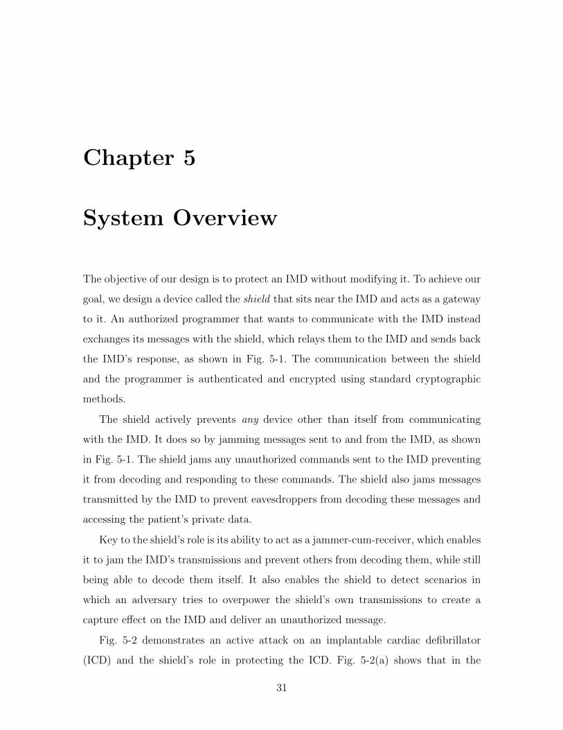
The objective of our design is to protect an IMD without modifying it. To achieve our
goal, we design a device called the shield that sits near the IMD and acts as a gateway
to it. An authorized programmer that wants to communicate with the IMD instead
exchanges its messages with the shield, which relays them to the IMD and sends back
the IMD’s response, as shown in Fig. 5-1. The communication between the shield
and the programmer is authenticated and encrypted using standard cryptographic
methods.
The shield actively prevents any device other than itself from communicating
with the IMD. It does so by jamming messages sent to and from the IMD, as shown
in Fig. 5-1. The shield jams any unauthorized commands sent to the IMD preventing
it from decoding and responding to these commands. The shield also jams messages
transmitted by the IMD to prevent eavesdroppers from decoding these messages and
accessing the patient’s private data.
Key to the shield’s role is its ability to act as a jammer-cum-receiver, which enables
it to jam the IMD’s transmissions and prevent others from decoding them, while still
being able to decode them itself. It also enables the shield to detect scenarios in
which an adversary tries to overpower the shield’s own transmissions to create a
capture effect on the IMD and deliver an unauthorized message.
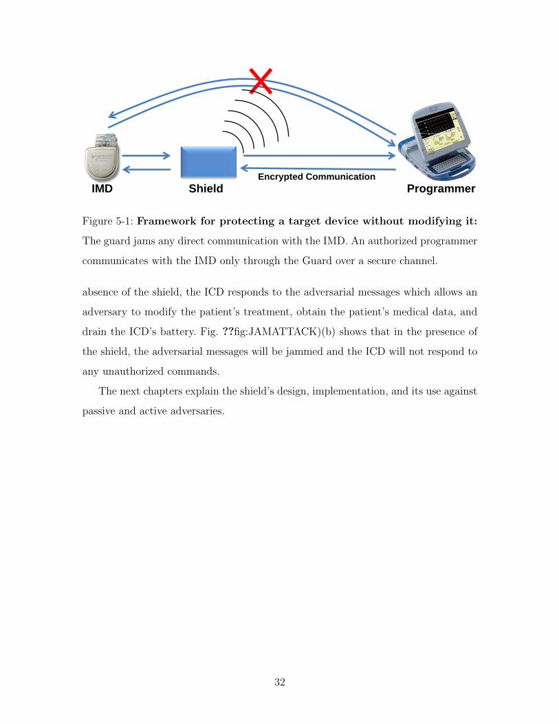
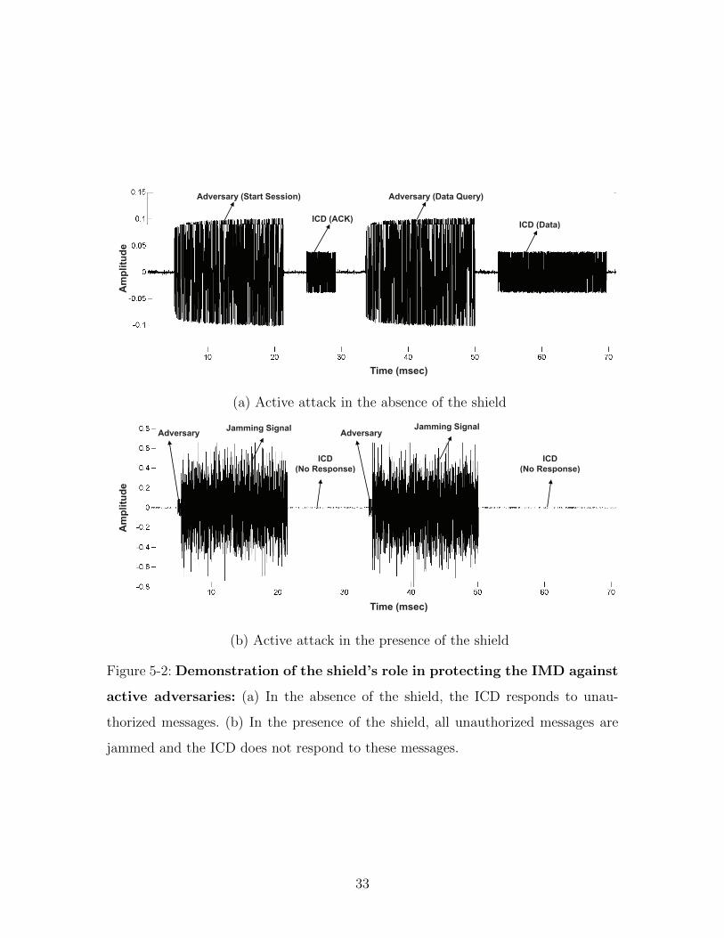
Fig. 5-2 demonstrates an active attack on an implantable cardiac defibrillator
(ICD) and the shield’s role in protecting the ICD. Fig. 5-2(a) shows that in the
31
Encrypted CommunicationProgrammerIMD Shield
Encrypted Communication
Figure 5-1: Framework for protecting a target device without modifying it:
The guard jams any direct communication with the IMD. An authorized programmer
communicates with the IMD only through the Guard over a secure channel.
absence of the shield, the ICD responds to the adversarial messages which allows an
adversary to modify the patient’s treatment, obtain the patient’s medical data, and
drain the ICD’s battery. Fig. ??fig:JAMATTACK)(b) shows that in the presence of
the shield, the adversarial messages will be jammed and the ICD will not respond to
any unauthorized commands.
The next chapters explain the shield’s design, implementation, and its use against
passive and active adversaries.
32
Adversary (Start Session) Adversary (Data Query)
ICD (Data)ICD (ACK)
ICD (Data)
mp
litu
de
Am
Time (msec)
(a) Active attack in the absence of the shield
Adversary Jamming Signal
Adversary Jamming Signal
ICD
(No Response)
ICD
(No Response)(No Response) (No Response)
mp
litu
de
Am
Time (msec)
(b) Active attack in the presence of the shield
Figure 5-2: Demonstration of the shield’s role in protecting the IMD against
active adversaries: (a) In the absence of the shield, the ICD responds to unau-
thorized messages. (b) In the presence of the shield, all unauthorized messages are
jammed and the ICD does not respond to these messages.
33

34
Chapter 6
Jammer-Cum-Receiver
A jammer-cum-receiver naturally needs to transmit and receive simultaneously. This
section presents a design for such a full-duplex radio. Our design has two key features:
First, it imposes no size restrictions and hence can be built as a small wearable device.
Second, it cancels the jamming signal only at the device’s receive antenna and at no
other point in space—a necessary requirement for jamming applications.
6.1 Full-Duplex Radio Design
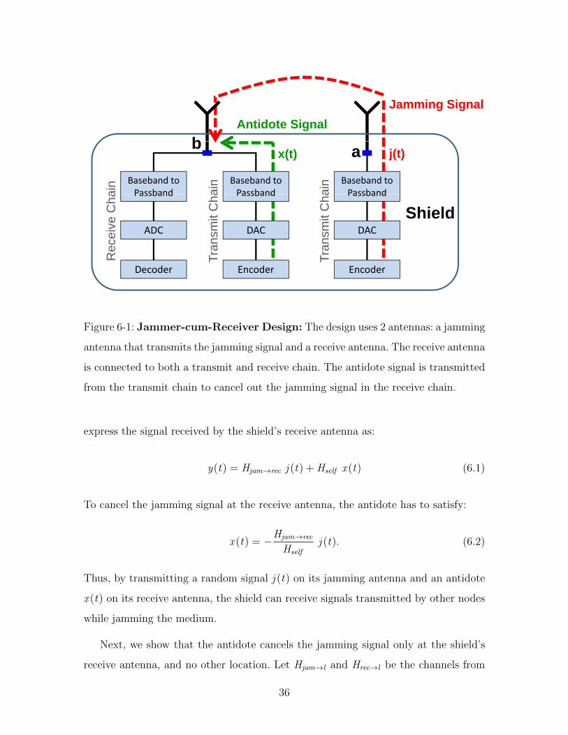
Our design, shown in Fig. 6-1, uses two antennas: a jamming antenna and a receive
antenna. The jamming antenna transmits a random jamming signal. The receive
antenna is simultaneously connected to both a transmit and a receive chain. The
transmit chain sends an antidote signal that cancels the jamming signal at the re-
ceive antenna’s front end, allowing the receive antenna to receive any signal without
disruption from its own jamming signal.
The antidote signal can be computed as follows. Let j (t) be the jamming signal
and x (t) be the antidote. Let Hself be the self-looping channel on the receive antenna
(i.e., the channel from the transmit chain to the receive chain on the same antenna)
and Hjam→rec the channel from the jamming antenna to the receive antenna. We can
35
Jamming SignalAntidote Signal
b
Baseband to Passband
Baseband to Passband
Baseband to Passband
ab
ain
ain ain
x(t) j(t)
Passband
ADC
Passband
DACDAC
Passband
Shieldan
smit
Cha
ecei
ve C
ha
ansm
it C
ha
Decoder EncoderEncoder
Tra
Re
Tra
Figure 6-1: Jammer-cum-Receiver Design: The design uses 2 antennas: a jamming
antenna that transmits the jamming signal and a receive antenna. The receive antenna
is connected to both a transmit and receive chain. The antidote signal is transmitted
from the transmit chain to cancel out the jamming signal in the receive chain.
express the signal received by the shield’s receive antenna as:
y(t) = Hjam→rec j (t) + Hself x (t) (6.1)
To cancel the jamming signal at the receive antenna, the antidote has to satisfy:
x (t) = −Hjam→rec
Hself
j (t). (6.2)
Thus, by transmitting a random signal j (t) on its jamming antenna and an antidote
x (t) on its receive antenna, the shield can receive signals transmitted by other nodes
while jamming the medium.
Next, we show that the antidote cancels the jamming signal only at the shield’s
receive antenna, and no other location. Let Hjam→l and Hrec→l be the channels from
36
the shield’s jamming and receive antennas to the adversary’s location l . An antenna
positioned at l receives the combined signal:
y = Hjam→l j (t) + Hrec→l x (t)
= (Hjam→l − Hrec→lHjam→rec
Hself
)j (t).
For the jamming signal to be cancelled out at location l , the following has to be
satisfied:Hjam→l
Hrec→l
=Hjam→rec
Hself
(6.3)
Locating the shield’s two antennas very close to each other ensures that at any location
l the attenuation from the two antennas is comparable, i.e., |Hjam→l
Hrec→l| ≈ 1 (see Chapter
7 in [46] for a detailed analysis). In contrast, |Hjam→rec
Hself| � 1; |Hself | is the attenuation on
the short wire between the transmit and receive chains in the receive antenna, which
is significantly less than the attenuation between the two antennas that additionally
have to go on the air [18]. For example, in our USRP2 prototype, the ratio |Hjam→rec
Hself| =
27 dB. Thus, the above condition is physically infeasible, and cancelling the jamming
signal at the shield’s receive antenna does not cancel it at any other location.
6.2 Design Properties
We note several ancillary properties of our design:
• Transmit and receive chains connected to the same antenna: Off-the-shelf radios
such as the USRP [13] have both a receive and a transmit chain connected to
the same antenna; they can in principle transmit and receive simultaneously on
the same antenna. Traditional systems cannot exploit this property, however,
because the transmit signal overpowers the receive chain, preventing the antenna
from decoding any signal but its own transmission. When the jamming signal
and the antidote signal cancel each other, the interference is cancelled and the
antenna can receive from other nodes while transmitting.
37
• Antenna cancellation vs. analog and digital cancellation: Cancelling the jam-
ming signal using an antidote signal is a form of antenna cancellation. Thus,
similar to the antenna cancellation proposed by Choi et al. [8], one can fur-
ther improve the performance by adding a hardware analog canceler [36]. In
this case, the input to the analog canceler will be taken from points a and b
in Fig. 6-1 and the output will be fed to the passband filter in the receive chain.
• Channel estimation: Computing the antidote in equation 6.2 requires knowing
the channels Hself and Hjam→rec. The shield estimates these channels using two
methods. First, during a session with the IMD, the shield measure the channels
immediately before it transmits to the IMD or jams the IMD’s transmission.
In the absence of an IMD session the shield periodically (i.e., every 200 ms)
estimates this channel by sending a probe. Since the shield’ two antennas are
close to each other, the probe can be sent at a low power, to allow other nodes
to leverage spatial reuse to concurrently access the medium.
38
Chapter 7
Protection from Passive
Eavesdroppers
To preserve the confidentiality of an IMD’s transmissions, the shield jams the IMD’s
signal on the channel. Since the wireless channel creates linear combinations of con-
currently transmitted signals, jamming with a random signal provides a form of one-
time pad, where only entities that know the jamming signal can decrypt the IMD’s
data [42]. The shield leverages its knowledge of the jamming signal and its jammer-
cum-receiver capability to receive the IMD’s data in the presence of jamming.
7.1 Specifications of Wireless IMD Communica-
tion
To realize our design goal, the shield must ensure that it jams every packet transmitted
by the IMD. To this end, the shield leverages two properties of MICS-band IMD
communications [1, 2]:
1. An IMD does not transmit except in a response to a message from a program-
mer. The shield can listen for programmer transmissions and anticipate when
the IMD may start transmitting.
2. An IMD transmits in response to a message from a programmer without sensing
39
0.3
0.35
0.4
e|
0.15
0.2
0.25 Query IMD ReplyIMD ReplyQueryA
mpl
itude
10 20 30 40 50 60 700
0.05
0.1
|A
10 20 30 40 50 60 70
Time (msec)
(a) Without Jamming
0.3
0.35
0.4 Jamming Jamming
e|
0.15
0.2
0.25
0.3
Query IMD ReplyIMD ReplyQuery
Am
plitu
de
10 20 30 40 50 60 700
0.05
0.1
|A
10 20 30 40 50 60 70
Time (msec)
(b) With Jamming
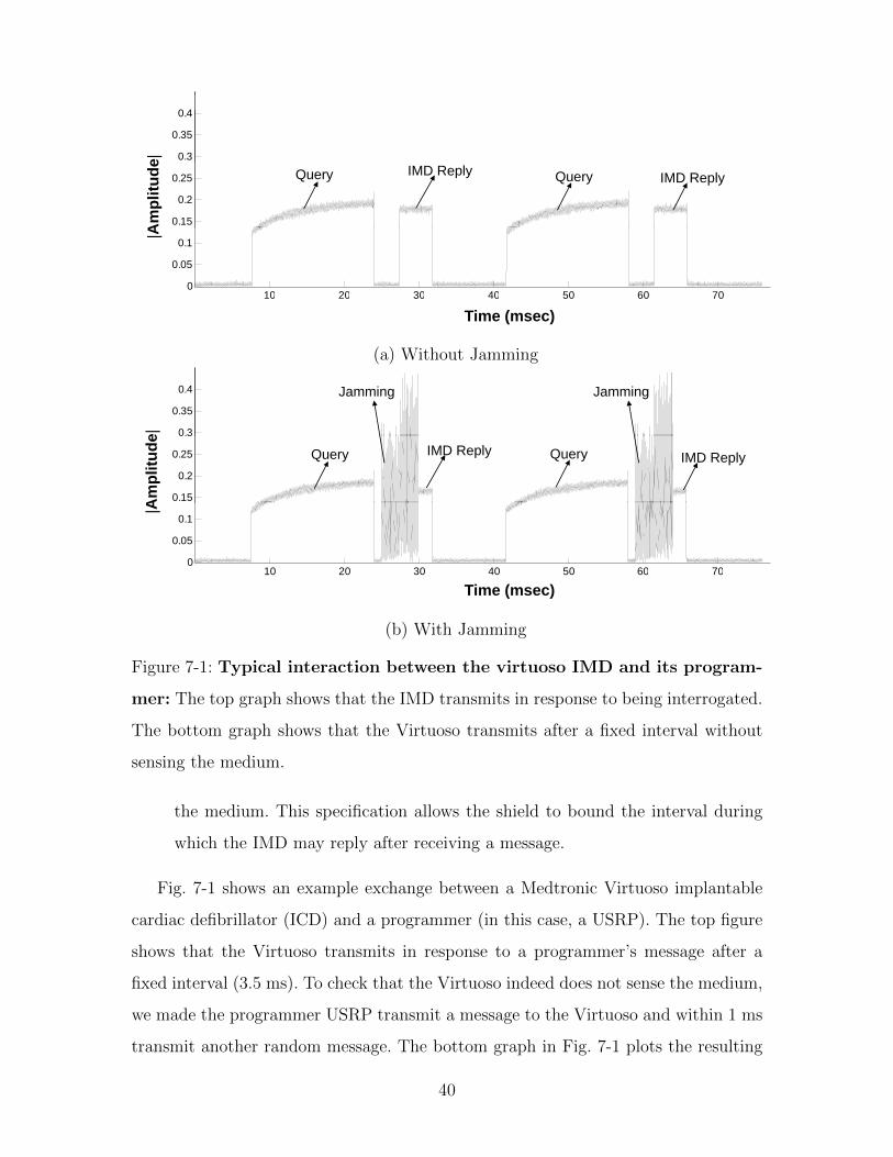
Figure 7-1: Typical interaction between the virtuoso IMD and its program-
mer: The top graph shows that the IMD transmits in response to being interrogated.
The bottom graph shows that the Virtuoso transmits after a fixed interval without
sensing the medium.
the medium. This specification allows the shield to bound the interval during
which the IMD may reply after receiving a message.
Fig. 7-1 shows an example exchange between a Medtronic Virtuoso implantable
cardiac defibrillator (ICD) and a programmer (in this case, a USRP). The top figure
shows that the Virtuoso transmits in response to a programmer’s message after a
fixed interval (3.5 ms). To check that the Virtuoso indeed does not sense the medium,
we made the programmer USRP transmit a message to the Virtuoso and within 1 ms
transmit another random message. The bottom graph in Fig. 7-1 plots the resulting
40
signal showing that the Virtuoso still transmitted after the same fixed interval even
though the medium was occupied.
7.2 Algorithm to Counter Passive Eavesdroppers
Given the above properties, the shield uses the following algorithm to jam the IMD’s
transmissions. Let T1 and T2 be the lower and upper bounds on the time that the IMD
takes to respond to a message, and let P be the IMD’s maximum packet duration.
Whenever the shield transmits a message to the IMD, it starts jamming the medium
exactly T1 milliseconds after the end of its transmission. While jamming, the shield
receives the signal on the medium using its receive antenna. The shield jams for a
duration of (T2 − T1) + P milliseconds.
Additionally, to deal with scenarios in which the IMD may transmit in response
to an unauthorized message, the shield uses its ability to detect active adversaries
that might succeed at delivering a message to the IMD (see §8). Whenever such an
adversary is detected, the shield uses the same algorithm above, as if the message
were sent to the IMD by the shield itself.
We note that each shield should calibrate the above parameters for its own IMD.
In particular, for the IMDs tested in this thesis, the above parameters are as follows:
T1 = 2.8 ms, T2 = 3.7 ms, and P = 21 ms.
7.2.1 Maximizing Jamming Efficiency for a Given Power Bud-
get
It is important to match the frequency profile of the jamming signal to the frequency
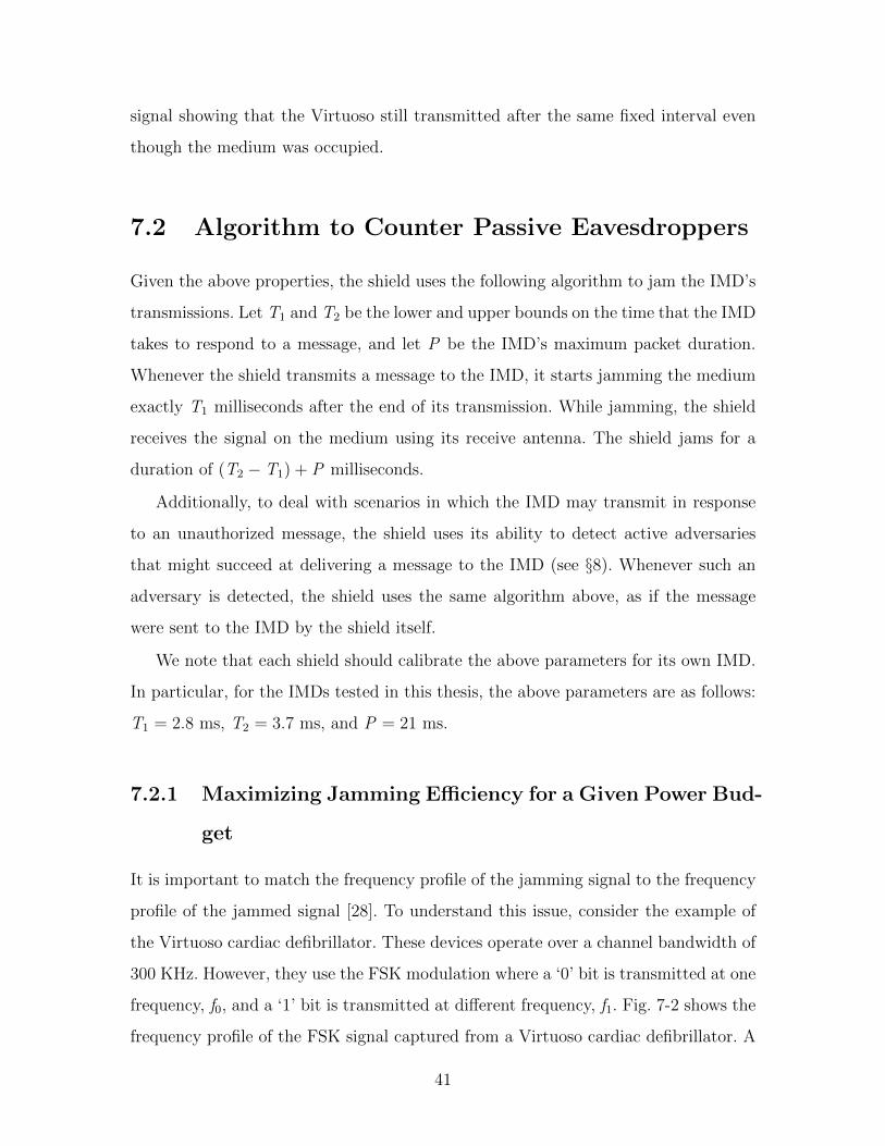
profile of the jammed signal [28]. To understand this issue, consider the example of
the Virtuoso cardiac defibrillator. These devices operate over a channel bandwidth of
300 KHz. However, they use the FSK modulation where a ‘0’ bit is transmitted at one
frequency, f0, and a ‘1’ bit is transmitted at different frequency, f1. Fig. 7-2 shows the
frequency profile of the FSK signal captured from a Virtuoso cardiac defibrillator. A
41
-150 -100 -50 0 50 100 150
Virt
uoso
ICD
Pow
er P
rofil
e
Frequency (kHz)
Figure 7-2: Frequency profile of IMD signal: The frequency profile of the FSK
signal captured from the Virtuoso cardiac defibrillator shows that most of the energy
is concentrated around ±50 KHz.
-150 -100 -50 0 50 100 150
Jam
min
g P
ower
Pro
file
Frequency (kHz)
IMD Power ProfileConstant Power ProfileShaped Power Profile
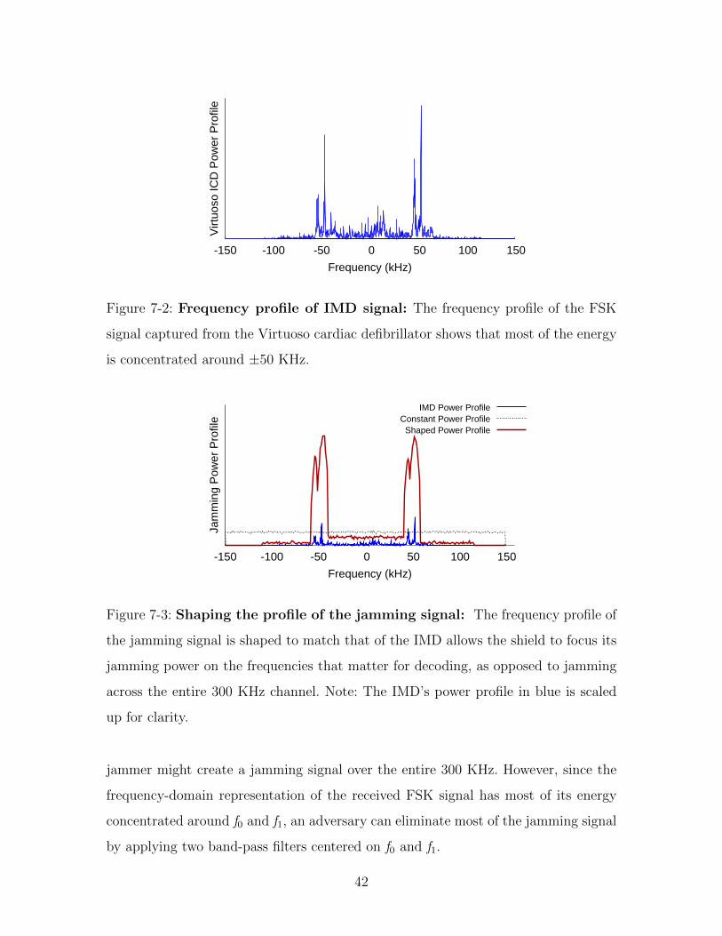
Figure 7-3: Shaping the profile of the jamming signal: The frequency profile of
the jamming signal is shaped to match that of the IMD allows the shield to focus its
jamming power on the frequencies that matter for decoding, as opposed to jamming
across the entire 300 KHz channel. Note: The IMD’s power profile in blue is scaled
up for clarity.
jammer might create a jamming signal over the entire 300 KHz. However, since the
frequency-domain representation of the received FSK signal has most of its energy
concentrated around f0 and f1, an adversary can eliminate most of the jamming signal
by applying two band-pass filters centered on f0 and f1.
42

Therefore, an effective jammer should consider the structure of the IMD’s signal
when crafting the jamming signal, shaping the amount of energy it puts in each
frequency according to the frequency profile of the IMD signal. Fig. 7-3 compares the
power profile of a jamming signal that is shaped to fit the signal in Fig. 7-2 and an
oblivious jamming signal that uses a constant power profile. The figure shows that the
shaped signal has increased jamming power in frequencies that matter for decoding.
To shape its jamming signal appropriately, the shield generates the jamming signal
by taking multiple random white Gaussian noise signals and assigning each of them
to a particular frequency bin in the 300 KHz MICS channel. The variance of the
white Gaussian noise in each frequency bin is picked to match the power profile
resulting from the IMD’s FSK modulation in that frequency bin. We then take the
IFFT of all the Gaussian signals to generate the time-domain jamming signal. This
process generates a random jamming signal that has a power profile similar to the
power profile generated by IMD modulation. The shield scales the amplitude of the
resulting jamming signal to match the power budget of its hardware. The shield also
compensates for any carrier frequency offset between its RF chain and that of the
IMD.
7.2.2 Ensuring Independence of Eavesdropper Location
To ensure confidentiality, the shield must maintain a high bit error rate (BER) at
the adversary, independent of the adversary’s location. The BER at the adversary,
however, strictly depends on its signal-to-interference-and-noise ratio, SINRA [18]. To
show that the BER at the adversary is independent of its location, we show that the
SINR at the adversary is independent of its location.
Suppose the IMD transmits its signal at a power Pi dB and the shield transmits
the jamming signal at a power Pj dB. The IMD’s signal and the jamming signal will
experience a pathloss to the adversary of Li and Lj , respectively. Thus, the SINRA
at the adversary can be written in dB as:
SINRA = (Pi − Li)− (Pj − Lj )− NA, (7.1)
43
where NA is the noise in the adversary’s hardware. Since the above equation is written
in the logarithmic scale (dB scale), the signal-to-interference-and-noise ratio translate
into subtractions as illustrated in the above equation.
The pathloss from the IMD to the adversary can be expressed as the sum of the
pathloss that the IMD’s signal experiences in the body and on the air, i.e., Li =
Lbody + Lair [35]. Since the shield and the IMD are close together, the pathlosses they
experience on the air to the adversary are approximately the same i.e., Lair ≈ Lj [46].
Thus, by substituting in equation 7.1 we rewrite the SINRA at the adversary as:
SINRA = (Pi − Lbody)− Pj − NA. (7.2)
The above equation shows that the SINR is independent of the adversary’s location
and can be controlled by setting the jamming power Pj to an appropriate value. This
directly implies that the BER at the adversary is independent of its location.
7.2.3 The SINR Tradeoff Between the Shield and the Adver-
sary
Similarly to how we computed the SINR of an eavesdropper, we can compute the
SINR of the shield (in dB) as:
SINRG = (Pi − Lbody)− (Pj −G)− NG , (7.3)
where NG is the thermal noise on the shield and G is the reduction in the jamming
signal power at the receive antenna due to the antidote. The above equation simply
states that SINRG is the IMD power after subtracting the pathloss due mainly to
in-body propagation, the residual of the jamming power (Pj −G), and the noise.
Note that if one ignores the noise on the shield’s receive antenna and the adver-
sary’s device (which are negligible in comparison to the other terms), one can express
44
the relation between the two SINRs using a simple equation:
SINRG = SINRA + G . (7.4)
This simplified view reveals an intrinsic tradeoff between the SINR at the shield and
the adversary, and hence their BERs. To increase the BER at the adversary while
maintaining a low BER at the shield, one needs to increase G , which is the amount of
jamming power cancelled at the shield’s receive antenna. We refer to G as the SINR
gap between the shield and the adversary.
We show in §10.1 that for the tested IMDs, an SINR gap of G = 32 dB suffices to
provide a BER of nearly 50% at the adversary (reducing the adversary to guessing)
while maintaining reliable packet delivery at the shield.
45

46
Chapter 8
Protection from Active Adversaries
Next, we explain our approach for countering active adversaries. At a high level, the
shield detects unauthorized packets and jams them. The jamming signal combines
linearly with the unauthorized signal, causing random bit flips during decoding. The
IMD ignores these packets because they fail its checksum test.
8.1 Algorithm to Counter Active Adversaries
The exact active jamming algorithm follow. Let Sid be an identifying sequence, i.e.,
a sequence of m bits that is always used to identify packets destined to the IMD.
Sid includes the packets’ physical-layer preamble and subsequent header, which con-
tains the device’s ID. When the shield is not transmitting, it constantly monitors
the medium. If it detects a signal on the medium, it proceeds to decode it. For each
newly decoded bit, the shield checks the last m decoded bits against the identifying
sequence Sid . If the two sequences differ by fewer than a threshold number of bits,
bthresh , the shield jams the signal until the signal stops and the medium becomes idle
again.
The shield also uses its receive antenna to monitor the medium while transmitting.
However, in this case, if it detects a signal concurrent to its transmission, it switches
from transmission to jamming and continues jamming until the medium becomes idle
again. The reason the shield jams any concurrent signal without checking for Sid is
47
to ensure that an adversary does not try to alter the shield’s own message on the
channel in order to send an unauthorized message to the IMD.
8.1.1 Choosing Unique Identifying Sequences
Our algorithm relies on the uniqueness of the identifying sequence Sid in order to
identify transmissions destined for the protected IMD. We therefore desire a method
of choosing a per-device Sid based on unique device characteristics. Fortunately, IMDs
already bear unique identifying characteristics. For example, the Medtronic IMDs that
we tested (the Virtuoso ICD and the Concerto CRT) use FSK modulation, a known
preamble and a header that contains the device’s ID, i.e., its 10-byte serial number.
More generally, each wireless device has an FCC ID, which allows the designer to
look up the device in the FCC database and verify its modulation, coding, frequency
and power profile [11]. One can use these specifications to choose an appropriate
identifying sequence.
8.1.2 Setting the Threshold bthresh
If an adversary can transmit a signal and force the shield to experience a bit error
rate higher than the IMD’s, it may prevent the shield from jamming an unauthorized
command that the IMD successfully decodes and executes. However, we argue that
such adversarial success is unlikely, for two reasons. First, because the signal goes
through body tissue, the IMD experiences an additional pathloss that could be as
high as 40 dB [39], and hence it naturally experiences a much weaker signal than
the shield. Second, the IMD uses a harder constraint to accept a packet than the
constraint the shield uses to jam a packet. Specifically, the IMD requires that all bits
be correct to pass a checksum, while the shield tolerates some differences between
the identifying sequence and the received one. We describe our empirical method of
choosing bthresh in §10.1.
48
8.1.3 Customizing for the MICS Band
It is important to realize that the shield can listen to the entire 3 MHz MICS band,
transmit in all or any subset of the channels in this band, and further continue to
listen to the whole band as it is transmitting in any subset of the channels. It is fairly
simple to build such a device by making the radio front-end wider than 3 MHz and
equipping the device with per-channel filters. This enables the shield to process the
signals from all channels in the MICS band simultaneously. Further the FCC rules [1]
do not prevent a device from using multiple channels simultaneously; neither do they
require a device that uses multiple channels to reduce its power in the individual
channels.
The shield uses this capability to monitor the entire 3 MHz MICS band because an
adversary can transmit to the IMD on any channel in the band. This monitoring allows
the shield to detect and counter adversarial transmissions even if the adversary uses
frequency hopping or transmit in multiple channels simultaneously to try to confuse
the shield . The shield jams any given 300 KHz channel if the channel contains a
signal that matches the constraints described in the active jamming algorithm.
8.1.4 Complying with FCC Rules
The shield must adhere to the FCC power limit even when jamming an adversary.
However, as explained in §4, a sophisticated adversary may use a transmission power
much higher than the FCC limit. In such case, it will be able to deliver its packet to
the IMD despite jamming. However, the shield is still useful because it can detect the
adversary in real time and raise an alarm to attract the attention of the patient or
her caregiver. Such alarms may be similar to a cell phone alarm, i.e., the shield may
beep or vibrate. It is desirable to have a low false positive rate for such an alarm.
To that end, we calibrate the shield with an IMD to find the minimum adversarial
transmit power that can trigger a response from the IMD despite jamming. We call
this value Pthresh . When the shield detects a potentially adversarial transmission, it
checks whether the signal power exceeds Pthresh , in which case it raises an alarm.
49
Finally, we note that when the shield detects a high-power active adversary, it
also considers the possibility that the adversary will send a message that triggers the
IMD to send its private data. In this case, the shield applies the passive jamming
algorithm: in addition to jamming the adversary’s high-power message, it jams the
medium afterward as detailed in §7.
8.1.5 The Shield’s Battery Life
Since jamming consumes power, one may wonder how often the shield needs to be
charged. In the absence of attacks, the shield only jams the IMD’s transmissions, and
hence transmits about as often as the IMD. IMDs are unchargeable power-limited
devices that cannot transmit frequently [14]. Thus, in this mode of operation, we do
not expect the battery of the shield to be an issue. When the IMD is under an active
attack, the shield will have to transmit as often as the adversary. However, since the
shield transmits at the FCC power limit for the MICS band, it can last for a day or
longer even if transmitting continuously. For example, wearable heart rate monitors
which continuously transmit ECG measurements can last 24–48 hours [25, 51].
50
Chapter 9
Experiment Setup
9.1 Implementation
We implement a proof-of-concept prototype shield with GNU Radio and USRP2
hardware [13, 17]. The prototype uses the USRP’s RFX400 daughterboards, which
operate in the MICS band [1]. The USRP2 does not support multiple daughterboards
on the same motherboard, so we implement a two-antenna shield with two USRP2
radio boards connected via an external clock so that they act as a single node. Our
implementation uses the FURY GPSDO clock model [23].
Our design for a two-antenna jammer-cum-receiver requires the receive antenna to
be always connected to both a transmit and a receive chain. By default, the USRP is
set up to toggle an antenna between transmission and reception. To enable the shield’s
receive antenna to transmit and receive simultaneously, we turn off the RX/TX switch,
which leaves both the transmit and receive chains connected to the antenna all the
time. Specifically, we set atr txval=0 and atr rxval=1<<5 in the TX chain, and
we set atr txval=1<<5 and atr rxval=1<<6 in the RX chain, by editing the
USRP2’s firmware and FPGA code. Finally, we equip the shield with FSK modulation
and demodulation capabilities so that it can communicate with an IMD.
51
9.2 Testing Environment
Our experiments use the following devices:
• Medtronic Virtuoso DR implantable cardiac defibrillator (ICD) in Fig. 9-1(b) [33].
• A Medtronic Concerto cardiac resynchronization therapy device (CRT) [31].
• A Medtronic Vitatron Carelink 2090 Programmer in Fig. 9-1(a) [32].
• USRP2 software radio boards in Fig. 9-1(c) [13].
In our experiments, the ICD and CRT play the role of the protected IMD. The
USRP devices play the roles of the shield, the adversary, and legitimate users of the
MICS band. We use the programmer off-line with our active adversary; the adversary
records the programmer’s transmissions in order to replay them later. Analog replay-
ing of these captured signals doubles their noise, reducing the adversary’s probability
of success, so the adversary demodulates the programmer’s FSK signal into the trans-
mitted bits to remove the channel noise. It then re-modulates the bits to obtain a
clean version of the signal to transmit to the IMD.
Fig. 9-3 depicts the testing setup. To simulate implantation in a human, we fol-
lowed prior work [21] and implanted each IMD beneath 1 cm of bacon, with 4 cm of
85% lean ground beef packed underneath. We placed the shield’s antenna next to the
IMD on the bacon’s surface to simulate a necklace as shown in Fig. 9-2. We varied
the adversary’s location between 20 cm and 27 meters, as shown in the figure.
52
(a) Programmer (c) USRP(b) Cardiac Defibrillator
Figure 9-1: Devices used in Evaluation:(a) Medtronic Vitatron Carelink 2090
Programmer. (b) Medtronic Virtuoso DR implantable cardiac defibrillators (ICDs).
(c) USRP2 software radio boards.
Figure 9-2: Simulating an human body environment : Each IMD is implanted
beneath 1 cm of bacon, with 4 cm of 85% lean ground beef packed underneath. We
placed the shield’s antennas next to the IMD on the bacon’s surface to simulate a
necklace
53
4 1
2
3
6
5
7
8
14
16 15 17
911
12
1318
Shield
IMD
Adversary
10
8.92 in
6.92in
8.8.8.8.8.929999 inininnn
Figure 9-3: Test bed setup: showing the locations of the shield and the IMD. We
experiment with 18 locations of the adversary which are shown as red boxes. The
locations are numbered according to received signal strength of the active adversary’s
transmission at the shield.
54
Chapter 10
Evaluation
We evaluate our prototype of a shield against commercially available IMDs. We show
that the shield effectively protects the confidentiality of the IMD’s messages and
defends the IMD against commands from unauthorized parties. We experiment with
both the Virtuoso ICD and the Concerto CRT. However, since the two IMDs did
not show any significant difference, we combine the experimental results from both
devices and present them together. Our results can be summarized as follows.
• In practice, our antenna cancellation design can cancel about 32 dB of the jam-
ming signal at the receive antenna (§10.1(a)). This result shows that our design
achieves similar performance to the antenna cancellation algorithm proposed in
prior work [8], but without requiring a large antenna separation.
• Setting the shield’s jamming power 20 dB higher than the IMD’s received power
allows the shield to achieve a high bit error rate at adversarial locations while
still being able to reliably decode the IMD’s transmissions (§10.1). The shield’s
increased power still complies with FCC rules in the MICS band since the
maximum transmit power of implanted devices is 20 dB less than the maximum
transmit power for devices outside the body [11].
• With the above setting, the bit error rate at a passive eavesdropper is nearly
50% at all tested locations—i.e., an eavesdropping adversary’s decoding efforts
are no more effective than random guessing. Further, even while jamming, the
55
shield can reliably decode the IMD’s packets with a packet loss rate less than
0.2%. We conclude that the guard and the IMD share an information channel
inaccessible to other parties (§10.2).
• When the shield is present and active, an adversary using off-the-shelf IMD
programmers cannot elicit a response from the protected IMD even from dis-
tances as small as 20 cm. A more sophisticated adversary that transmits at 100
times the shield’s power successfully elicits IMD responses only at distances
less than 5 meters, and only in line-of-sight locations. Further, the shield de-
tects these high-power transmissions and raises an alarm. We conclude that the
shield significantly raises the bar for such high power adversarial transmissions
(§10.3).
56
0
0.2
0.4
0.6
0.8
1
20 22 24 26 28 30 32 34 36 38 40
CD
F
Nulling of the Jamming Signal (dB)
Figure 10-1: Antenna cancellation: The antidote signal reduces the jamming signal
on average by 32 dB.
10.1 Micro-Benchmark Results
In this section, we calibrate the parameters of the shield and examine the performance
of its components.
10.1.1 Antenna Cancellation
We first evaluate the performance of the antenna cancellation algorithm described
in §6, in which the shield sends an antidote signal to cancel the jamming signal on
its receive antenna.
In this experiment, the shield transmits a random signal on its jamming antenna
and the jamming signal’s antidote on its receive antenna. In each run, it transmits
100 Kb without the antidote, followed by 100 Kb with the antidote. We compute the
received power at the receive antenna with and without the antidote. The difference in
received power between the two trials represents the amount of jamming cancellation
resulting from the transmission of the antidote.
Fig. 10-1 shows the CDF of the amount of cancellation over multiple runs of the
experiment. It shows that the average reduction in jamming power is about 32 dB.
The figure also shows that the variance of this value is small. This result shows
57
that the antenna cancellation algorithm introduced in this thesis achieves similar
performance to the antenna cancellation algorithm proposed by Choi et al. [8], but
without requiring a large antenna separation1.
10.1.2 Tradeoffs Between Eavesdropper Error and Shield Er-
ror
The aforementioned 32 dB of cancellation at the shield’s receive antenna naturally sets
an upper bound on the jamming power: if the residual error after jamming cancellation
is too high, the shield will fail to decode the IMD’s data properly.
To explore the tradeoff between the error at the shield and the error at an eaves-
dropper, we run the following experiment. We place the IMD and the shield at their
marked locations in Fig. 9-3, and we place a USRP eavesdropper 20 cm away from
the IMD at location 1. In each run of the experiment, the shield repeatedly triggers
the IMD to transmit the same packet. The shield also uses its jammer-cum-receiver
capability to simultaneously jam and decode the IMD’s packets. The eavesdropper
tries to decode the IMD packets, in the presence of jamming, using an optimal FSK
decoder [34].
Fig. 10-2(a) plots the eavesdropper’s BER as a function of the shield’s jamming
power. Since the required jamming power naturally depends on the power of the
jammed IMD’s signal, the x-axis reports the shield’s jamming power relative to the
power of the signal it receives from the IMD. The figure shows that if the shield sets
its jamming power 20 dB higher than the power of the signal it receives from the
IMD, the BER at an eavesdropper is 50%, which means the eavesdropper’s decoding
task is no more successful than random guessing.
Next, we check that the above setting allows the shield to reliably decode the
IMD’s packets. As above, Fig. 10-2(b) plots the shield’s packet loss rate as a function
1Choi et al. [8] also combine antenna cancellation with analog and digital cancellation to obtain atotal cancellation of 60 dB at the receive antenna. However, we show in §10.2 that for our purposes,a cancellation of 32 dB suffices to achieve our goal of high reliability at the shield and nearly 50%BER at the adversary.
58
0
0.1
0.2
0.3
0.4
0.5
0.6
0 5 10 15 20 25
BE
R a
t the
Adv
ersa
ry
Jamming Power relative to IMD Power (dB)
BER = 0.5
(a) BER at the Adversary
0
0.05
0.1
0.15
0.2
0 5 10 15 20 25
Pac
ket L
oss
at S
hiel
d
Jamming Power relative to IMD Power (dB)
PER = 0.002
(a) Fraction of Lost IMD Packet at the Shield
Figure 10-2: Tradeoff between BER at the eavesdropper and reliable decod-
ing at the shield: The figure shows that if the shield sets its jamming power 20 dB
higher than the power it receives from the IMD, it can ensure that an eavesdropper
sees a BER around 50%—effectively reducing the eavesdropper to guessing—while
keeping the packet loss rate (PER) at the shield as low as 0.2%.
of its jamming power relative to the power of the signal it receives from the IMD.
The figure shows that if the shield’s jamming power is 20 dB higher than the IMD’s
power, the packet loss rate is no more than 0.2%. We conclude that this jamming
59
power achieves both a high error rate at the eavesdropper and reliable decoding at
the shield.
We note that the shield’s increased power, described above, complies with FCC
rules on power usage in the MICS band. This is because the transmit power of im-
planted devices is 20 dB less than the maximum allowed transmit power for devices
outside the body [11].
10.1.3 Setting the Jamming Parameters
Next we calibrate the jamming parameters for countering active adversaries. The
shield must jam unauthorized packets sent to the IMD it protects. Further, it must
jam these packets even if it receives them with some bit errors, because they might
otherwise be received correctly at the IMD. We therefore experimentally estimate an
upper bound, bthresh , on the number of bit flips an IMD accepts in an adversary’s
packet header. The shield can use this upper bound to identify packets that must be
jammed.
To estimate bthresh , we perform the following experiment. First, a USRP transmits
unauthorized commands to the IMD to trigger it to send patient data. We repeat
the experiment for all locations in Fig. 9-3. The shield stays in its marked location
in Fig. 9-3, but its jamming capability is turned off. However, the shield logs all of
the packets transmitted by the IMD as well as the adversarial packets that triggered
them. We process these logs offline and, for packets that successfully triggered an
IMD response despite containing bit errors, we count the number of bit flips in the
packet header. Our results show that it is unlikely that a packet will have bit errors
at the shield but still be received correctly by the IMD. Out of 5000 packets, only
three packets showed errors at the shield but still triggered a response from an IMD.
The maximum number of bit flips in those packets was 2, so we conservatively set
bthresh = 4.
Next, we measure Pthresh , the minimum adversary RSSI at the shield that can elicit
a response from the IMD in the presence of jamming. To do so, we fix the location of
the IMD and the shield as shown in Fig. 9-3. Again we use a USRP that repeatedly
60
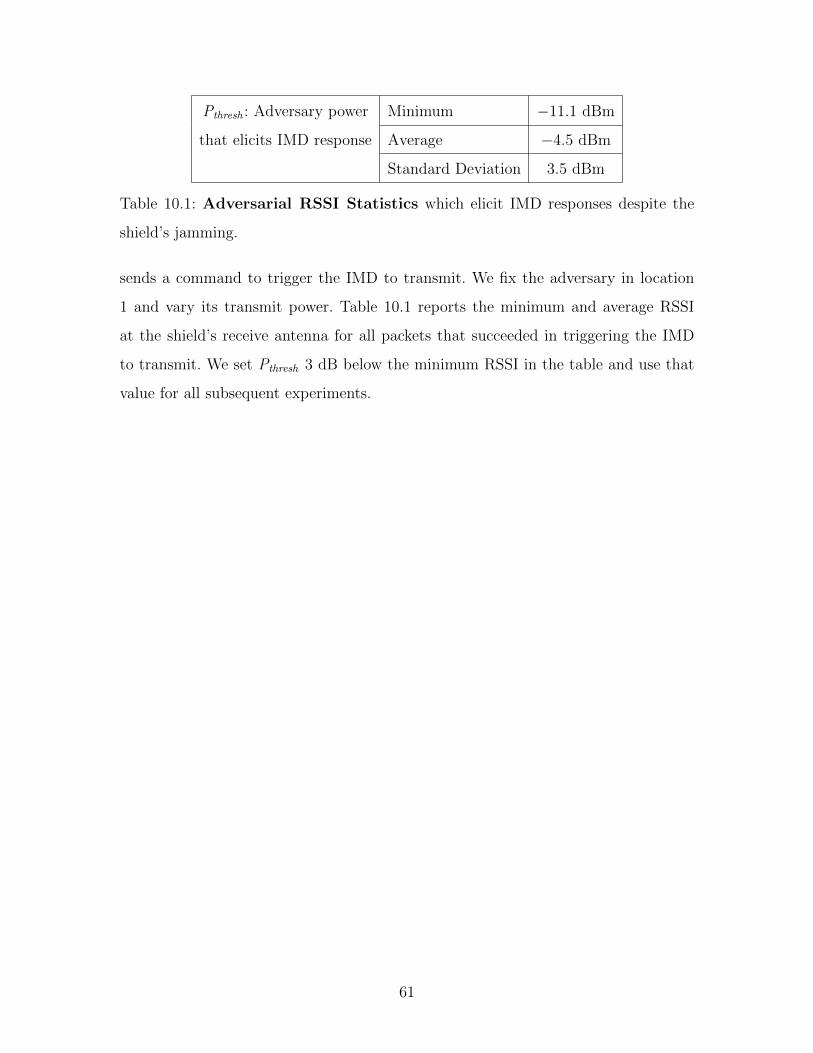
Pthresh : Adversary power Minimum −11.1 dBm
that elicits IMD response Average −4.5 dBm
Standard Deviation 3.5 dBm
Table 10.1: Adversarial RSSI Statistics which elicit IMD responses despite the
shield’s jamming.
sends a command to trigger the IMD to transmit. We fix the adversary in location
1 and vary its transmit power. Table 10.1 reports the minimum and average RSSI
at the shield’s receive antenna for all packets that succeeded in triggering the IMD
to transmit. We set Pthresh 3 dB below the minimum RSSI in the table and use that
value for all subsequent experiments.
61
10.2 Protecting from Passive Adversaries
In this section, we evaluate the shield’s ability to protect the confidentiality of the
IMD’s transmissions. We show that, irrespective of an eavesdropper’s location, the
shield can cause the eavesdropper to experience a BER of nearly 50% while main-
taining its own ability to decode the IMD’s packets reliably.
To evaluate the effectiveness of the shield’s jamming, we run an experiment in
which the shield repeatedly triggers the IMD to transmit the same packet. The shield
also uses its jammer-cum-receiver capability to jam the IMD’s packets while it decodes
them. We set the shield’s jamming power as described in §7. In each run, we position
an eavesdropper at a different location in Fig. 9-3, and make the IMD send 1000
packets. The eavesdropping adversary attempts to decode the IMD packets using an
optimal FSK decoder [34]. We record the BER at the eavesdropper and the packet
loss rate at the shield.
Fig. 10-3 plots a CDF of the eavesdropper’s BER taken over all locations in
Fig. 9-3. The CDF shows that the eavesdropper’s BER is nearly 50% in all tested
locations. We conclude that our design of the shield achieves the goal of protecting
the confidentiality of IMD’s transmissions from an eavesdropper regardless of the
eavesdropper’s location.
For the same experiment, Fig. 10-4 plots a CDF of the packet loss rate of IMD-
transmitted packets at the shield. Each point on the x-axis refers to the packet loss
rate over 1000 IMD packets. The average packet loss rate is about 0.2%, considered
low for wireless systems [12]. Such a low loss rate is due to two factors. First, we locate
the shield fairly close to the IMD, so it receives the IMD’s signal at a relatively high
SNR. Second, the jamming cancellation is sufficient to maintain a high SNR that
ensures a low packet loss rate. We conclude that the shield can decode the IMD’s
packets reliably, even while jamming.
62
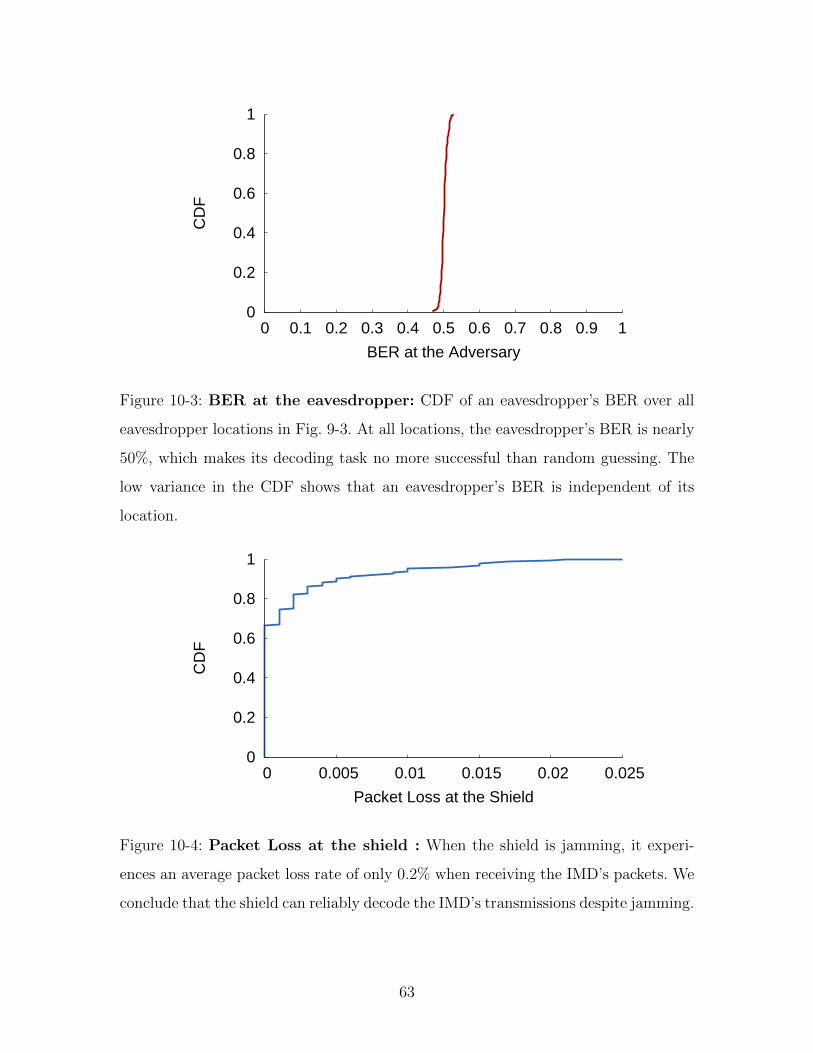
0
0.2
0.4
0.6
0.8
1
0 0.1 0.2 0.3 0.4 0.5 0.6 0.7 0.8 0.9 1
CD
F
BER at the Adversary
Figure 10-3: BER at the eavesdropper: CDF of an eavesdropper’s BER over all
eavesdropper locations in Fig. 9-3. At all locations, the eavesdropper’s BER is nearly
50%, which makes its decoding task no more successful than random guessing. The
low variance in the CDF shows that an eavesdropper’s BER is independent of its
location.
0
0.2
0.4
0.6
0.8
1
0 0.005 0.01 0.015 0.02 0.025
CD
F
Packet Loss at the Shield
Figure 10-4: Packet Loss at the shield : When the shield is jamming, it experi-
ences an average packet loss rate of only 0.2% when receiving the IMD’s packets. We
conclude that the shield can reliably decode the IMD’s transmissions despite jamming.
63
10.3 Protecting from Active Adversaries
We distinguish between two scenarios representing different levels of adversarial so-
phistication. In the first, we consider scenarios in which the adversary uses an off-the-
shelf IMD programmer to send unauthorized commands to the IMD. In the second,
a more sophisticated adversary reverse-engineers the protocol and uses custom hard-
ware to transmit with much higher power than is possible in the first scenario.
10.3.1 Adversary Using a Commercial IMD Programmer
The simplest way an adversary can send unauthorized commands to an IMD is to
obtain a standard IMD programmer and use its built-in radio. Because commercial
programmers abide by FCC rules, in this scenario the adversary’s transmission power
will be comparable to that of the shield.
Using an IMD programmer we obtained via a popular auction website, we play
the role of such an active adversary. We use the setup in Fig. 9-3, fixing the IMD’s
and shield’s locations and transmitting unauthorized commands from all the marked
locations. As shown in the figure, we experiment with both line-of-sight and non-line-
of-sight locations as well as nearby (20 cm) and relatively far locations (30 m).
To test whether the shield’s jamming is effective against unauthorized commands,
regardless of which unauthorized command the adversary chooses to send, we experi-
ment with two types of adversarial commands: those that trigger the IMD to transmit
its data with the objective of depleting its battery, and those that change the IMD’s
therapy parameters. In each location, we play each command 100 times with the
shield on and 100 times with the shield off. After each attempt, we check whether
the command was successful. To determine whether the first type of command was
successful—i.e., whether it elicited a reply—we sandwiched a USRP observer along
with the IMD between the two slabs of meat. To allow the USRP observer to eas-
ily check whether the IMD transmitted in response to the adversary’s command, we
configure the shield to jam only the adversary’s packets, not the packets transmitted
by the IMD. To determine whether a therapy modification command was successful,
64
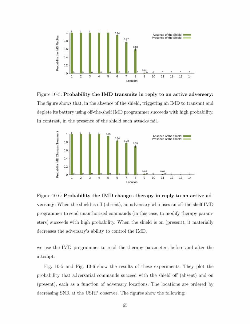
0
0.2
0.4
0.6
0.8
1
1 2 3 4 5 6 7 8 9 10 11 12 13 14
Pro
babi
lity
the
IMD
Rep
lies
Location
0 0 0 0 0 0 0 0 0 0 0 0 0 0
1 1 1 1 10.94
0.77
0.59
0.01
Absence of the ShieldPresence of the Shield
Figure 10-5: Probability the IMD transmits in reply to an active adversery:
The figure shows that, in the absence of the shield, triggering an IMD to transmit and
deplete its battery using off-the-shelf IMD programmer succeeds with high probability.
In contrast, in the presence of the shield such attacks fail.
0
0.2
0.4
0.6
0.8
1
1 2 3 4 5 6 7 8 9 10 11 12 13 14Pro
babi
lity
IMD
Cha
nges
Tre
atm
ent
Location
0 0 0 0 0 0 0 0 0 0 0 0 0 0
1 1 1 1 0.95
0.840.78
0.70
0.02 0.01
Absence of the ShieldPresence of the Shield
Figure 10-6: Probability the IMD changes therapy in reply to an active ad-
versary: When the shield is off (absent), an adversary who uses an off-the-shelf IMD
programmer to send unauthorized commands (in this case, to modify therapy param-
eters) succeeds with high probability. When the shield is on (present), it materially
decreases the adversary’s ability to control the IMD.
we use the IMD programmer to read the therapy parameters before and after the
attempt.
Fig. 10-5 and Fig. 10-6 show the results of these experiments. They plot the
probability that adversarial commands succeed with the shield off (absent) and on
(present), each as a function of adversary locations. The locations are ordered by
decreasing SNR at the USRP observer. The figures show the following:
65
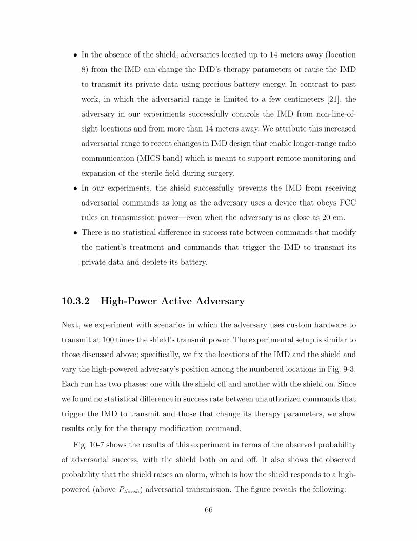
• In the absence of the shield, adversaries located up to 14 meters away (location
8) from the IMD can change the IMD’s therapy parameters or cause the IMD
to transmit its private data using precious battery energy. In contrast to past
work, in which the adversarial range is limited to a few centimeters [21], the
adversary in our experiments successfully controls the IMD from non-line-of-
sight locations and from more than 14 meters away. We attribute this increased
adversarial range to recent changes in IMD design that enable longer-range radio
communication (MICS band) which is meant to support remote monitoring and
expansion of the sterile field during surgery.
• In our experiments, the shield successfully prevents the IMD from receiving
adversarial commands as long as the adversary uses a device that obeys FCC
rules on transmission power—even when the adversary is as close as 20 cm.
• There is no statistical difference in success rate between commands that modify
the patient’s treatment and commands that trigger the IMD to transmit its
private data and deplete its battery.
10.3.2 High-Power Active Adversary
Next, we experiment with scenarios in which the adversary uses custom hardware to
transmit at 100 times the shield’s transmit power. The experimental setup is similar to
those discussed above; specifically, we fix the locations of the IMD and the shield and
vary the high-powered adversary’s position among the numbered locations in Fig. 9-3.
Each run has two phases: one with the shield off and another with the shield on. Since
we found no statistical difference in success rate between unauthorized commands that
trigger the IMD to transmit and those that change its therapy parameters, we show
results only for the therapy modification command.
Fig. 10-7 shows the results of this experiment in terms of the observed probability
of adversarial success, with the shield both on and off. It also shows the observed
probability that the shield raises an alarm, which is how the shield responds to a high-
powered (above Pthresh) adversarial transmission. The figure reveals the following:
66
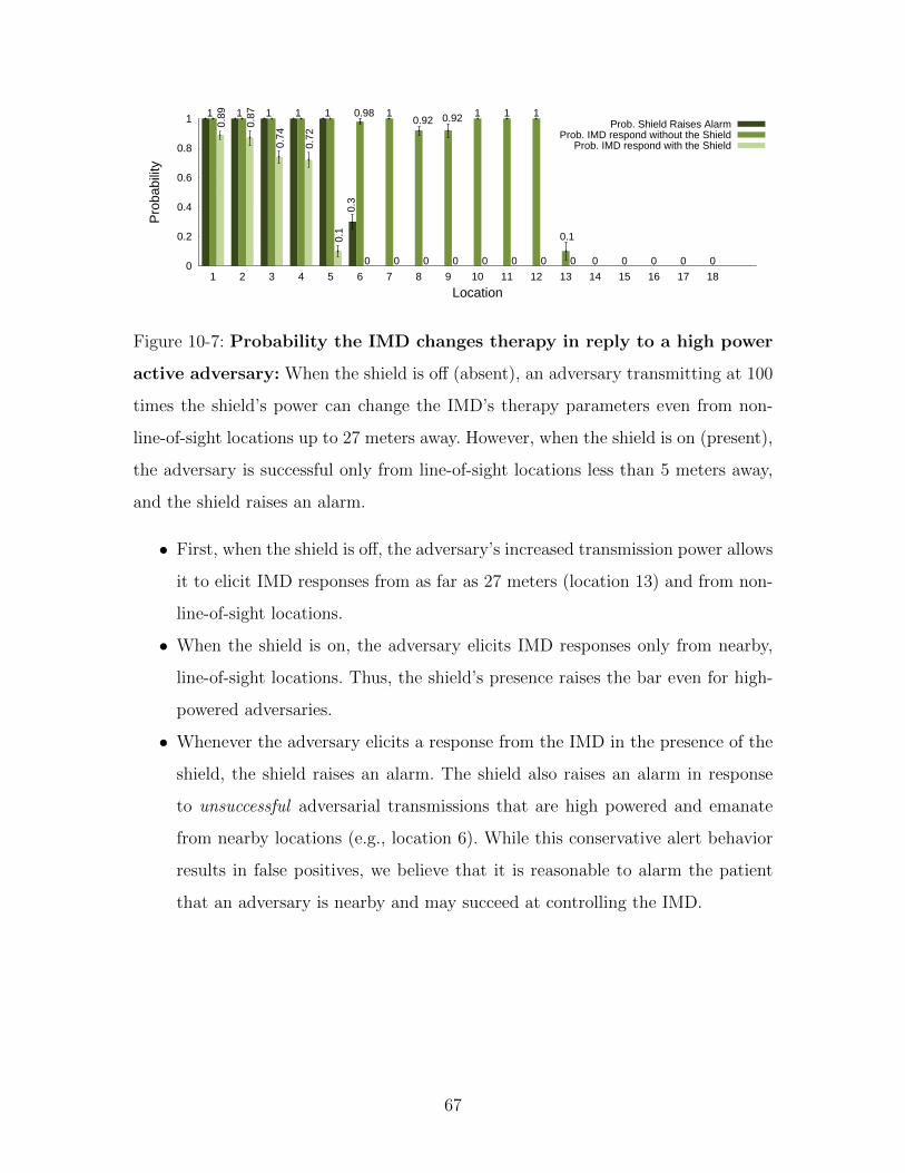
0
0.2
0.4
0.6
0.8
1
1 2 3 4 5 6 7 8 9 10 11 12 13 14 15 16 17 18
Pro
babi
lity
Location
1 1 1 1 1 1 1 1 10.980.92 0.92
0.1
0.89
0.87
0.74
0.72
0.1
0.3
0 0 0 0 0 0 0 0 0 0 0 0 0
Prob. Shield Raises AlarmProb. IMD respond without the Shield
Prob. IMD respond with the Shield
Figure 10-7: Probability the IMD changes therapy in reply to a high power
active adversary: When the shield is off (absent), an adversary transmitting at 100
times the shield’s power can change the IMD’s therapy parameters even from non-
line-of-sight locations up to 27 meters away. However, when the shield is on (present),
the adversary is successful only from line-of-sight locations less than 5 meters away,
and the shield raises an alarm.
• First, when the shield is off, the adversary’s increased transmission power allows
it to elicit IMD responses from as far as 27 meters (location 13) and from non-
line-of-sight locations.
• When the shield is on, the adversary elicits IMD responses only from nearby,
line-of-sight locations. Thus, the shield’s presence raises the bar even for high-
powered adversaries.
• Whenever the adversary elicits a response from the IMD in the presence of the
shield, the shield raises an alarm. The shield also raises an alarm in response
to unsuccessful adversarial transmissions that are high powered and emanate
from nearby locations (e.g., location 6). While this conservative alert behavior
results in false positives, we believe that it is reasonable to alarm the patient
that an adversary is nearby and may succeed at controlling the IMD.
67
10.4 Coexistence
Next, we investigate how the presence of a shield affects other legitimate users of
the medium. As explained in §3, the FCC rules for medical devices in the MICS
band require such devices to monitor a candidate channel for 10 ms and avoid using
occupied channels. As a result, two pairs of honest medical devices are unlikely to
share the same 300 KHz channel. Thus, we focus our evaluation on coexistence with
the meteorological devices that are the primary users of the MICS band (and hence
can transmit even on occupied channels).
In this experiment, we position the IMD and the shield in the locations marked
on Fig. 9-3. We make a USRP board alternate between sending unauthorized com-
mands to the IMD and transmitting cross-traffic unintended for the IMD. The cross-
traffic is modeled after the transmissions of meteorological devices. In particular, our
cross-traffic models the traffic generated by Vaisala digital radiosonde RS92-AGP [6]
which uses GMSK modulation. For each of the adversary positions in Fig 9-3, we make
the USRP alternate between one packet to the IMD and one cross-traffic packet. The
shield logs all of the packets it detects and reports which of them it jammed.
Post-processing of the shield’s log showed that the shield did not jam any of the
cross-traffic packets, regardless of the transmitter’s location. In contrast, the shield
jammed all of the packets that it detected were addressed to the IMD; see Table 10.2.
Further, our software radio implementation of the shield takes 270 µs after an ad-
versary stops transmitting (standard deviation of 23 µs) to turn-around and stop its
own transmissions. This delay is mainly due to the shield’s being implemented in
software. A hardware implementation would have a more efficient turn-around time
of tens of microseconds. (Note, for example, that a 802.11 card can turn around in
a SIFS duration of 10 µs). The low turn-around time shows that the shield does not
continuously jam the medium (thereby denying others access to it).
68
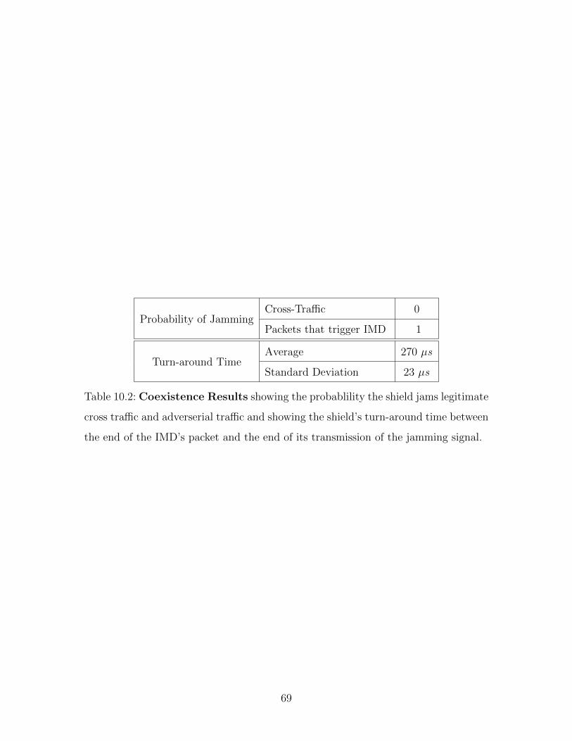
Probability of JammingCross-Traffic 0
Packets that trigger IMD 1
Turn-around TimeAverage 270 µs
Standard Deviation 23 µs
Table 10.2: Coexistence Results showing the probablility the shield jams legitimate
cross traffic and adverserial traffic and showing the shield’s turn-around time between
the end of the IMD’s packet and the end of its transmission of the jamming signal.
69

70
Chapter 11
Conclusion
The influx of wireless communication in medical devices brings a number of domain-
specific problems that require the expertise of both the wireless and security commu-
nities. This thesis addresses the problem of communication security for implantable
medical devices. The key challenge in addressing this problem stems from the difficulty
of modifying or replacing implanted devices. We present the design and implemen-
tation of a wireless physical-layer solution that delegates the task of protecting IMD
communication to an external device called the shield. Our evaluation shows that
the shield effectively provides confidentiality for IMDs’ transmitted data and shields
IMDs from unauthorized commands, both without requiring any changes to the IMDs
themselves.
71

72
Bibliography
[1] MICS Medical Implant Communication Services, Federal Communications Com-
mission, FCC 47CFR95.601-95.673 Subpart E/I Rules for MedRadio Services.
[2] ITU-R Recommendation RS.1346 :Sharing between the meteorological aids ser-
vice and medical implant communication systems (MICS) operating in the mobile
service in the frequency band 401-406 MHz. International Telecommunications
Union, 1998.
[3] ETSI EN 301 839-1 V1.3.1. European Telecommunications Standard Institute,
2009.
[4] Medtronic’s paradigm veo wireless insulin pump helps prevent hypoglycemia.
MedGadget Internet Journal for emerging medical technologies, September 2009.
[5] Radio Standards Specification RSS-243: Medical Devices Operating in the 401-
406 MHz Frequency Band. Spectrum Management and Telecommunications,
February 2010.
[6] Jussi Akerberg. State-of-the-art Radiosonde Telemetry. Vaisala Oyj, Helsinki,
Finland.
[7] Sriram Cherukuri, Krishna K Venkatasubramanian, and Sandeep K S Gupta.
Biosec: A biometric based approach for securing communication in wireless net-
works of biosensors implanted in the human body. In Parallel Processing Work-
shops, International Conference on, Los Alamitos, CA, USA, 2003. IEEE Com-
puter Society.
73

[8] Jung Choi, Mayank Jain, Kannan Srinivasan, Philip Levis, and Sachin Katti.
Achieving single channel, full duplex wireless communication. In ACM Mobicom,
2010.
[9] Tamara Denning, Alan Borning, Batya Friedman, Brian T. Gill, Tadayoshi
Kohno, and William H. Maisel. Patients, pacemakers, and implantable defib-
rillators: human values and security for wireless implantable medical devices.
2010.
[10] Tamara Denning, Kevin Fu, and Tadayoshi Kohno. Absence Makes the Heart
Grow Fonder: New Directions for Implantable Medical Device Security. In Pro-
ceedings of USENIX Workshop on Hot Topics in Security, 2008.
[11] Device. FCC ID is LF5MICS. ”FCC records can be obtained from a dynamically
generated webpage by entering the FCCID www.fcc.gov/searchtools.html”.
[12] David Eckhardt and Peter Steenkiste. Measurement and analysis of the error
characteristics of an in-building wireless network. In In Proceeding ACM SIG-
COMM 1996.
[13] Ettus. Inc. USRP2 Universal Software Radios. http://www.ettus.com.
[14] Carl Falcon. Inside implantable devices. Medical Design Technology, October.
[15] Kevin Fu. Trustworthy medical device software. In Public Health Effectiveness
of the FDA 510(k) Clearance Process: Measuring Postmarket Performance and
Other Select Topics: Workshop Report. IOM (Institute of Medicine), National
Academies Press.
[16] Kevin Fu. Inside risks, reducing the risks of implantables medical devices: A
prescription to improve security and privacy of pervasive health care. In Com-
munications of the ACM, 2009.
[17] GNURadio. http://www.gnu.org/software/gnuradio.
74
[18] Andrea Goldsmith. Wireless Communications. Cambridge University Press,
2005.
[19] Shyamnath Gollakota and Dina Katabi. Physical layer security made fast and
channel-independent. In Proceedings of INFOCOM, 2011.
[20] Daniel Halperin, Thomas S. Heydt-Benjamin, Kevin Fu, Tadayoshi Kohno, and
William H. Maisel. Security and privacy for implantable medical devices. IEEE
Pervasive Computing, 7(1), January 2008.
[21] Daniel Halperin, Thomas S. Heydt-Benjamin, Benjamin Ransford, Shane S.
Clark, Benessa Defend, Will Morgan, Kevin Fu, Tadayoshi Kohno, and
William H. Maisel. Pacemakers and implantable cardiac defibrillators: Software
radio attacks and zero-power defenses. In IEEE Symposium on Security and
Privacy, May 2008.
[22] I.Csiszar and J. Korner. Broadcast channels with confidential messages. IEEE
Trans. on Info. Theory, 1978.
[23] Jackson. Labs. Fury GPSDO. http://www.jackson-labs.com/.
[24] W. C. Jakes. Microwave Mobile Communications. Wiley, 1974.
[25] Zhanpeng Jin, Yuwen Sun, and A.C. Cheng. Predicting cardiovascular disease
from real-time electrocardiographic monitoring: An adaptive machine learning
approach on a cell phone. In Engineering in Medicine and Biology Society,
EMBC 2009. Annual International Conference of the IEEE.
[26] M. Koplow, A. Chen, D. Steingart, P.K. Wright, and J.W. Evans. Thick film
thermoelectric energy harvesting systems for biomedical applications. In Medical
Devices and Biosensors, 2008.
[27] Yao Liu, Peng Ning, Huaiyu Dai, and An Liu. Randomized differential dsss:
Jamming-resistant wireless broadcast communication. In Proceedings of IEEE
INFOCOM 2010.
75

[28] J. Lopatka. Adaptive generating of the jamming signal. In Military Communi-
cations Conference, MILCOM 1995.
[29] W. H. Maisel. Safety issues involving medical devices. In Journal of the American
Medical Association, August 2005.
[30] Ivan Martinovic, Paul Pichota, and Jens Schmitt. Jamming for good: A fresh
approach to authentic communication in wsns. In Proceedings of the ACM con-
ference on Wireles network security (WiSec), 2009.
[31] Medtronic. Inc. Concerto II CRT-D: Digital implantable car-
dioverter defibrillator with cardiac resynchronization therapy.
http://www.medtronic.com/your-health/heart-failure/device/cardiac-
resynchronization-therapy-defibrillators/concerto/index.htm.
[32] Medtronic. Inc. Medtronic CareLink Programmer.
http://www.medtronic.com/for-healthcare-professionals/products-
therapies/cardiac-rhythm/patient-management-carelink/medtronic-carelink-
programmer/index.htm.
[33] Medtronic. Inc. Virtuoso DR/VR: Implantable cardioverter defibril-
lator systems. http://www.medtronic.com/your-health/ sudden-cardiac-
arrest/device/our-implantable-defibrillators/ virtuoso/index.htm.
[34] H. Meyr, M. Moeneclaey, and S. A. Fechtel. Digital Communication Receivers:
Synchronization, Channel Estimation, and Signal Processing. John Wiley and
Sons Inc., 1998.
[35] Dorin Panescu. Wireless communication systems for implantable medical devices.
IEEE engineering in medicine and biology, 2008.
[36] B. Radunovic, D. Gunawardena, P. Key, A. Proutiere, N. Singh, H. V. Balan, and
G. Dejean. Rethinking indoor wireless: Low power, low frequency, full-duplex.
Technical Report Microsoft Research, 2009.
76
[37] Melanie Rieback, Bruno Crispo, and Andrew Tanenbaum. Rfid guardian: A
battery-powered mobile device for rfid privacy management. In Proceedings of
the Australasian Conference on Information Security and Privacy, 2005.
[38] Naveen Santhapuri, Romit Roy Choudhury, Justin Manweiler, Srihari
Nelakuduti, Souvik Sen, and Kamesh Munagala. Message in message mim: A
case for reordering transmissions in wireless networks. In In HotNets, 2008.
[39] Kamran Sayrafian-Pour, Wen-Bin Yang, John Hagedorn, Judith Terrill,
Kamya Yekeh Yazdandoost, and Kiyoshi Hamaguchi. Channel models for medi-
cal implant communication. International Journal of Wireless Information Net-
works, 17(3-4), December 2010.
[40] Stuart Schechter. Security that is meant to be skin deep: Using ultraviolet mi-
cropigmentation to store emergency-access keys for implantable medical devices.
In First USENIX Workshop on Health Security and Privacy (HealthSec), Wash-
ington, DC, August 2010.
[41] Michael Scheffler, Etienne Hirt, and Andreas Caduff. Wrist-wearable medical
devices: technologies and applications. Medical Device Technology, 2003.
[42] Claude Shannon. Communication theory of secrecy systems. Bell System Tech-
nical Journal, 28:656–715, 1949.
[43] Victor Shnayder, Bor rong Chen, Konrad Lorincz, Thaddeus R. F. Fulford-jones,
and Matt Welsh. Abstract sensor networks for medical care. Technical Report,
Harvard University.
[44] C Popper Mario Strasser and Srdjan Capkun. Jamming-resistant broadcast com-
munication without shared keys. In Proceedings of the USENIX Security Sym-
posium, 2009.
[45] A Thangaraj, S Dihidar, A R Calderband, S W McLaughlin, and K M Merolla.
Capacity achieving codes for the wiretap channel with applications to quantum
key distribution. CoRR, 2004.
77
[46] D. Tse and P. Vishwanath. Fundamentals of Wireless Communications. Cam-
bridge University Press, 2005.
[47] G. Virone, A. Wood, L. Selavo, Q. Cao, L. Fang, T. Doan, Z. He, R. Stoleru,
S. Lin, and J. A. Stankovic. An advanced wireless sensor network for health
monitoring. In Transdisciplinary Conference on Distributed Diagnosis and Home
Healthcare (D2H2), 2006.
[48] A.D. Wyner. The wire-tap channel. Bell Tech Journal, 1975.
[49] S Xiao, A Dhamdhere, V Sivaraman, and A Burdett. Transmission Power Control
in Body Area Sensor Networks for Healthcare Monitoring. In JSAC, 2009.
[50] Fengyuan Xu, Zhengrui Qin, Chiu C. Tan, Baosheng Wang, and Qun Li. Md-
guard: Securing implantable medical devices with the external wearable guardian.
In Proceedings of INFOCOM 2011.
[51] Zephyr. Inc. BioHarness BT. http://www.zephyr-technology.com/bioharness-bt.
[52] Chunliu Zhan, William B. Baine, Artyom Sedrakyan, and Steiner Claudia.
Cardiac device implantation in the united states from 1997 through 2004: A
population-based analysis. Journal of General Internal Medicine, 23(1), 2007.
78