en - gm รับออกแบบ ... 600.pdf · permanently on: decimal point permanently on:...
TRANSCRIPT

EMPlus 600
Electronic digital indicatorEN
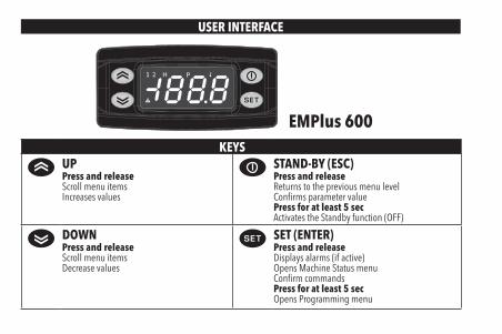
USER INTERFACE
EMPlus 600KEYS
UPPress and releaseScroll menu itemsIncreases values
STAND-BY (ESC)Press and releaseReturns to the previous menu levelConfirms parameter valuePress for at least 5 secActivates the Standby function (OFF)
DOWNPress and releaseScroll menu itemsDecrease values
SET (ENTER)Press and releaseDisplays alarms (if active)Opens Machine Status menuConfirm commandsPress for at least 5 secOpens Programming menu
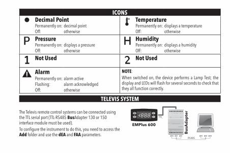
ICONSDecimal Point TemperaturePermanently on: decimal point Permanently on: displays a temperatureOff: otherwise Off: otherwise
Pressure HumidityPermanently on: displays a pressure Permanently on: displays a humidityOff: otherwise Off: otherwise
Not Used Not Used
Alarm NOTE:When switched on, the device performs a Lamp Test; the display and LEDs will flash for several seconds to check that they all function correctly.
Permanently on: alarm activeFlashing: alarm acknowledgedOff: otherwise
TELEVIS SYSTEM
The Televis remote control systems can be connected using the TTL serial port (TTL-RS485 BusAdapter 130 or 150 interface module must be used).To configure the instrument to do this, you need to access the Add folder and use the dEA and FAA parameters.
RS485
Bu
sAd
apte
r
EMPlus 600
TTL
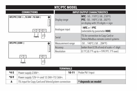
NTC/PTC MODELCONNECTIONS INPUT/OUTPUT CHARACTERISTICS
Display rangeNTC: -50...110°C (-58...230°F)PTC: -50...140°C (-58...302°F)on display with 3½ digits + sign
Analogue input1 NTC or 1 PTC(selectable by parameter H00)
SerialTTL for connection to Copy Card orTelevis/Modbus remote control systems
Measurement range -50 ... 140°C (-58 ... 284°F)Accuracy better than 0.5% of end of scale +1 digitResolution 0.1°C (0.1°F up to +199.9°F; 1°F over)
NTC/PTC (12Va/c, 12-24Va/12-36Vc)
Supply Pb1
8 9 10 11
NTC/PTC (230Va)
Supply Pb1
4 5 10 11
TERMINALS*4-5 Power supply 230Va. 10-11 Probe Pb1 Input
*8-9 Power supply 12Va/c and 12-24Va/12-36Vc.
A TTL input for Copy Card and TelevisSystem connection * depends on model
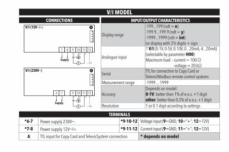
V/I MODELCONNECTIONS INPUT/OUTPUT CHARACTERISTICS
Display range
-199...199 (ndt = n)-199.9...199.9 (ndt = y)-1999...1999 (ndt = int)on display with 3½ digits + sign
Analogue input
1 V/I (0-1V, 0-5V, 0-10V, 0...20mA, 4...20mA)(selectable by parameter H00)Maximum load: - current = 100 Ω
- voltage = 20 kΩ
SerialTTL for connection to Copy Card orTelevis/Modbus remote control systems
Measurement range -1999 ... 1999
AccuracyDepends on model:0-1V: better than 1% of e.o.s. +1 digitother: better than 0.5% of e.o.s. +1 digit
Resolution 1 or 0.1 digit according to settings
V/I (12Va/c)
+12VI
V+ +−
Supply
7 8 9 10 11 12
V/I (230Va)
+12VI
V+ +−
Supply
76 9 10 11 12
TERMINALS*6-7 Power supply 230Va. *9-10-12 Voltage input (9=GND; 10=”+”; 12=12V)
*7-8 Power supply 12Va/c. *9-11-12 Current input (9=GND; 11=”+”; 12=12V)
A TTL input for Copy Card and TelevisSystem connection * depends on model
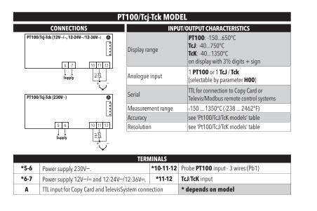
PT100/Tcj-Tck MODELCONNECTIONS INPUT/OUTPUT CHARACTERISTICS
Display range
PT100: -150...650°CTcJ: -40...750°CTcK: -40...1350°Con display with 3½ digits + sign
Analogue input1 PT100 or 1 TcJ / Tck(selectable by parameter H00)
SerialTTL for connection to Copy Card orTelevis/Modbus remote control systems
Measurement range -150 ... 1350°C (-238 ... 2462°F)Accuracy see ‘Pt100/TcJ/TcK models’ tableResolution see ‘Pt100/TcJ/TcK models’ table
PT100/Tcj-Tck (12Va/c, 12-24Va/12-36Vc)
Supply Pb1
+ −
6 7 10 11 12
PT100/Tcj-Tck (230Va)
Supply Pb1
+ −
65 10 11 12
TERMINALS*5-6 Power supply 230Va. *10-11-12 Probe PT100 input - 3 wires (Pb1)
*6-7 Power supply 12Va/c and 12-24Va/12-36Vc. *11-12 TcJ/TcK input
A TTL input for Copy Card and TelevisSystem connection * depends on model
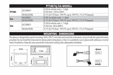
PT100/Tcj-Tck MODELs
PT100:ACCURACY: 0.5% for whole scale + 1 digit
0.2% from -150 to 300°CRESOLUTION: 0.1°C (0.1°F) from -199.9°C up to 199.9°C; 1°C (1°F) beyond
TcJ:ACCURACY: 0.4% for whole scale + 1 digitRESOLUTION: 0.1°C (0.1°F) from -199.9°C up to 199.9°C; 1°C (1°F) beyond
Tck:ACCURACY: 0.5% for whole scale + 1 digit
0.3% from -40 to 800°CRESOLUTION: 0.1°C (0,1°F) from -199.9°C up to 199.9°C; 1°C (1°F) beyond
MOUNTING - DIMENSIONSThe device is designed for panel mounting. Drill a 29x71 mm hole and insert the instrument; secure it with the special brackets provided. Do not install the instrument in damp and/or dirty places; in fact, it is suitable for use in places with ordinary or normal levels of pollution. Keep the area around the instrument cooling slots adequately ventilated.
74 mm
32 m
m
29 m
m
71 mm70 mm
59 m
m
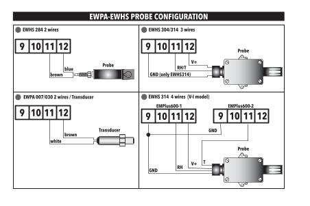
EWPA-EWHS PROBE CONFIGURATION
EWPA 007/030 2 wires / Transducer
Transducerbrown
white
9 10 11 12
EWHS 304/314 3 wires
Probe
GND (only EWHS314)
V+RH/T
9 10 11 12
EWHS 284 2 wires
Probe
brownblue
9 10 11 12
EWHS 314 4 wires (V-I model)
Probe
GNDV+
RHT
GND
EMPlus600-1 EMPlus600-2
9 10 11 12 9 10 11 12
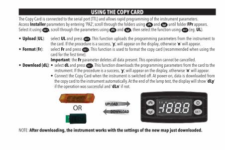
USING THE COPY CARDThe Copy Card is connected to the serial port (TTL) and allows rapid programming of the instrument parameters. Access Installer parameters by entering ‘PA2’, scroll through the folders using and until folder FPr appears. Select it using , scroll through the parameters using and , then select the function using (eg. UL).
• Upload (UL): select UL and press . This function uploads the programming parameters from the instrument to the card. If the procedure is a success, ‘y’, will appear on the display, otherwise ‘n’ will appear.
• Format (Fr): select Fr and press . This function is used to format the copy card (recommended when using the card for the first time).Important: the Fr parameter deletes all data present. This operation cannot be cancelled.
• Download (dL): • select dL and press . This function downloads the programming parameters from the card to the instrument. If the procedure is a success, ‘y’, will appear on the display, otherwise ‘n’ will appear.
• Connect the Copy Card when the instrument is switched off. At power-on, data is downloaded from the copy card to the instrument automatically. At the end of the lamp test, the display will show ‘dLy’ if the operation was successful and ‘dLn’ if not.
UPLOAD
DOWNLOADOR
NOTE: After downloading, the instrument works with the settings of the new map just downloaded.
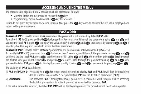
ACCESSING AND USING THE MENUsThe resources are organized into 2 menus which are accessed as follows:
• ‘Machine Status’ menu: press and release the key.• ‘Programming’ menu: hold down the key for 5 seconds.
Either do not press any keys for 15 seconds (timeout) or press the key once, to confirm the last value displayed and return to the previous screen.
PASSWORDPassword ‘PA1’: used to access User parameters. The password is not enabled by default (PS1=0).To enable it (PS1≠0): press and hold for longer than 5 seconds, scroll through the parameters using and until you see the label PS1, press to display the value, modify it using and , then save it by pressing or . If enabled, it will be required in order to access the User parameters.Password ‘PA2’: used to access Installer parameters. The password is enabled by default (PS2=15).To modify it (PS2≠15): press and hold for longer than 5 seconds, scroll through the parameters using and until you see the label PA2, press , set the value to ‘15’ using and , then confirm using . Scroll through the folders until you find the label diS and press to enter. Scroll through the parameters using and until you see the label PS2, press to display the value, modify it using and , then save it by pressing or .
The visibility of ‘PA2’ is as follows:1) PA1 and PA2 ≠ 0: Press and hold for longer than 5 seconds to display PA1 and PA2. It will then be possible to
decide whether to access the ‘User’ parameters (PA1) or the ‘Installer’ parameters (PA2).2) Otherwise: The password PA2 is amongst the level1 parameters. If enabled, it will be required when accessing
the Installer parameters; to enter it, proceed as instructed for password PA1.If the value entered is incorrect, the label PA1/PA2 will be displayed again and the procedure will need to be repeated.
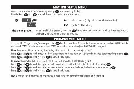
MACHINE STATUS MENUAccess the Machine Status menu by pressing and releasing the key.Use the keys and to scroll through all the folders in the menu:
- AL: alarms folder (only visible if an alarm is active);
- Pb1: probe 1 - Pb1 folder;
Displaying probes: when label Pb1 is present, press the key to view the value measured by the corresponding probe (NOTE: the value cannot be modified).
PROGRAMMING MENUTo access the ‘Programming’ menu, press the key for more than 5 seconds. If specified, an access PASSWORD will be requested: ‘PA1’ for User parameters and ‘PA2’ for Installer parameters (see ‘PASSWORD’ paragraph).
User Parameter: When accessed, the display will show the first parameter (e.g. ‘HAL’).Press and to scroll through all the parameters on the current level. Select the desired parameter by pressing . Press and to modify it and to save the changes.
Installer Parameter: When accessed, the display will show the first folder (e.g. ‘AL’).Press and to scroll through the folders on the current level. Select the desired folder using .Press and to scroll through the parameters in the current folder and select the parameter using .Press and to modify it and to save the changes.
NOTE: Switch the instrument off and on again each time the parameter configuration is changed.
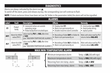
DIAGNOSTICSAlarms are always indicated by the alarm icon .To switch off the alarm, press and release any key; the corresponding icon will continue to flash.
NOTE: If alarm exclusion times have been set (see ‘AL’ folder in the parameters table) the alarm will not be signalled.
ALARMSLabel Fault Description Effects Remedy
E1 Probe1faulty
• measured values are outside operating range
• Probe faulty/short-circuited/open
• Display label E1• Alarm icon permanently on• Disable max/min alarm controller
• check probe type (H00)• check probe wiring• replace probe
AH1 Alarm for HIGHvalue (Pb1)
value read by Pb1 ≥ HAL after time of tAO.(see “MAX/MIN TEMPERATURE ALARMS“)
• Recording of label AH1 in folder AL• Alarm icon permanently on
Wait until value read by Pb1 returns below HAL-AFd.
AL1 Alarm for LOWvalue (Pb1)
value read by Pb1 ≤ LAL after time of tAO.(see “MAX/MIN TEMPERATURE ALARMS“)
• Recording of label AL1 in folder AL• Alarm icon permanently on
Wait until value read by Pb1 returns above LAL+AFd.
MAX/MIN TEMPERATURE ALARM
LAL
AFd
HAL
AFd
LAL + AFd HAL - AFd
Minimum temperature alarm: Temp. ≤ LAL (LAL with sign)
Maximum temperature alarm: Temp. ≥ HAL (HAL with sign)
Returning from min temp. alarm: Temp. ≥ LAL + AFd
Returning from max temp. alarm: Temp. ≤ HAL - AFd
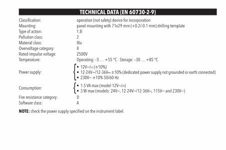
TECHNICAL DATA (EN 60730-2-9)Classification: operation (not safety) device for incorporationMounting: panel mounting with 71x29 mm (+0.2/-0.1 mm) drilling templateType of action: 1.BPollution class: 2Material class: IIIaOvervoltage category: IIRated impulse voltage: 2500VTemperature: Operating: –5 … +55 °C - Storage: –30 … +85 °C
Power supply:• 12Va/c (±10%)• 12-24Va/12-36Vc ±10% (dedicated power supply not grounded or earth connected)• 230Va ±10% 50/60 Hz
Consumption: • 1.5 VA max (model 12Va/c)• 3 W max (models: 24Va, 12-24Va/12-36Vc, 115Va and 230Va)
Fire resistance category: DSoftware class: A
NOTE: check the power supply specified on the instrument label.
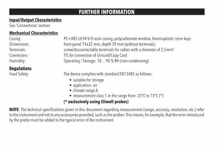
FURTHER INFORMATIONInput/Output CharacteristicsSee ‘Connections’ section
Mechanical CharacteristicsCasing: PC+ABS UL94 V-0 resin casing, polycarbonate window, thermoplastic resin keysDimensions: front panel 74x32 mm, depth 59 mm (without terminals)Terminals: screw/disconnectable terminals for cables with a diameter of 2,5mm2
Connectors: TTL for connection of Unicard/Copy CardHumidity: Operating / Storage: 10…90 % RH (non-condensing)
RegulationsFood Safety: The device complies with standard EN13485 as follows:
• suitable for storage• application: air• climate range A• measurement class 1 in the range from -25°C to 15°C (*)
(* exclusively using Eliwell probes)
NOTE: The technical specifications given in this document regarding measurement (range, accuracy, resolution, etc.) refer to the instrument and not to any accessories provided, such as the probes. This means, for example, that the error introduced by the probe must be added to the typical error of the instrument.
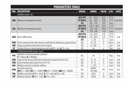
PARAMETERS TABLEPAR. DESCRIPTION MODEL RANGE VALUE U.M. LEVEL
ALARMs (folder 'AL')
HAL Maximum temperature alarm.NTC/PTC LAL...150.0 50.0 °C/°F
User/InstPT100-Tc LAL...1999 1200 °C/°FV/I LAL...150 150 num
LAL Minimum temperature alarm.NTC/PTC -150.0...HAL -50.0 °C/°F
User/InstPT100-Tc -328...HAL -199,9 °C/°FV/I -150...HAL -150 num
AFd Alarm differential.NTC/PTC 1.0...50.0 2.0 °C/°F
InstPT100-Tc 1.0...50.0 2.0 °C/°FV/I 1...50 2 num
PAO Alarm exclusion time after device is switched on following a power failure. ALL 0...10 0 hours InsttAO Delay preceding temperature alarm signal. ALL 0...250 1 min InsttP Enable all keys to acknowledge an alarm. n (0) = no; y (1) = yes. ALL n/y y flag Inst
COMMUNICATION (folder 'Add')
PtS Selection of communication protocol.t = Televis; d = Modbus. ALL t/d t flag Inst
dEA Index of the device within the family (valid values from 0 to 14). ALL 0...14 0 num InstFAA Device family (valid values from 0 to 14). ALL 0...14 0 num InstAdr Modbus protocol controller address. ALL 1...255 1 num Inst
bAU Baudrate selection.48 (0) = 4800; 96 (1) = 9600; 192 (2) = 19200; 384 (3) = 38400. ALL 48/96/
192/384 96 num Inst
Pty Modbus parity bit. n (0) = none; E (1) = even; o (2) = odd. ALL n/E/o E num InstStP Modbus stop bit. 1b (0) = 1 bit; 2b (1) = 2 bit. ALL 1b/2b 1b flag Inst
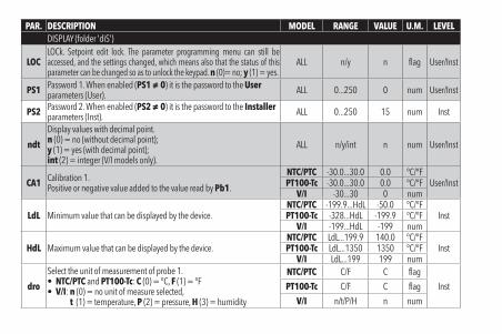
PAR. DESCRIPTION MODEL RANGE VALUE U.M. LEVELDISPLAY (folder 'diS')
LOCLOCk. Setpoint edit lock. The parameter programming menu can still be accessed, and the settings changed, which means also that the status of this parameter can be changed so as to unlock the keypad. n (0)= no; y (1) = yes.
ALL n/y n flag User/Inst
PS1 Password 1. When enabled (PS1 ≠ 0) it is the password to the User parameters (User). ALL 0...250 0 num User/Inst
PS2 Password 2. When enabled (PS2 ≠ 0) it is the password to the Installer parameters (Inst). ALL 0...250 15 num Inst
ndt
Display values with decimal point.n (0) = no (without decimal point);y (1) = yes (with decimal point);int (2) = integer (V/I models only).
ALL n/y/int n num User/Inst
CA1 Calibration 1.Positive or negative value added to the value read by Pb1.
NTC/PTC -30.0...30.0 0.0 °C/°FUser/InstPT100-Tc -30.0...30.0 0.0 °C/°F
V/I -30...30 0 num
LdL Minimum value that can be displayed by the device.NTC/PTC -199.9...HdL -50.0 °C/°F
InstPT100-Tc -328...HdL -199.9 °C/°FV/I -199...HdL -199 num
HdL Maximum value that can be displayed by the device.NTC/PTC LdL...199.9 140.0 °C/°F
InstPT100-Tc LdL...1350 1350 °C/°FV/I LdL...199 199 num
dro
Select the unit of measurement of probe 1.• NTC/PTC and PT100-Tc: C (0) = °C, F (1) = °F• V/I: n (0) = no unit of measure selected,
t (1) = temperature, P (2) = pressure, H (3) = humidity
NTC/PTC C/F C flag
InstPT100-Tc C/F C flag
V/I n/t/P/H n num
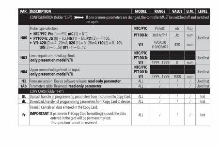
PAR. DESCRIPTION MODEL RANGE VALUE U.M. LEVELCONFIGURATION (folder 'CnF') If one or more parameters are changed, the controller MUST be switched off and switched
on again.
H00
Probe type selection.• NTC/PTC: Ptc (0) = PTC, ntC (1) = NTC• PT100-Tc: Jtc (0) = TcJ, Htc (1) = Tck, Pt1 (2) = PT100. • V/I: 420 (0) = 4...20mA, 020 (1) = 0...20mA, t10 (2) = 0...10V,
t05 (3) = 0...5V, t01 (4) = 0...1V.
NTC/PTC Ptc/ntC ntc flag
User/InstPT100-Tc Jtc/Htc/Pt1 Jtc num
V/I 420/020t10/t05/t01 420 num
H03 Lower input current/voltage limit.(only present on model V/I)
NTC/PTCUser/InstPT100-Tc
V/I -1999...1999 0 num
H04 Upper current/voltage limit for input.(only present on model V/I)
NTC/PTCUser/InstPT100-Tc
V/I -1999...1999 1000 numrEL firmware version. Device software release: read-only parameter. ALL / / / User/InsttAb Parameters table. Reserved: read-only parameter. ALL / / / User/Inst
COPY CARD (folder 'FPr')UL Upload. Transfer of programming parameters from instrument to Copy Card. ALL / / / InstdL Download. Transfer of programming parameters from Copy Card to device. ALL / / / Inst
Fr
Format. Cancels all data entered in the Copy Card.
IMPORTANT: If parameter Fr (Copy Card formatting) is used, the data entered in the card will be permanently lost.This operation cannot be reversed.
ALL / / / Inst
ELECTRICAL CONNECTIONsAttention! Make sure the machine is switched off before working on the electrical connections.The instrument is equipped with screw or disconnectable terminal blocks for connecting electrical cables with a max. diameter of 2,5mm2.Make sure the power supply voltage complies with that required by the instrument.NTC/PTC/PT100 probes have no connection polarity and can be extended using a normal bipolar cable (Note that extending the probes burdens the behaviour of the instrument in terms of EMC electromagnetic compatibility: specifically, if Pt100 probes with cable longer than 3 mt are used, an extreme care must be taken during wiring operations).
CONDITIONS OF USEPermitted useFor safety reasons, the instrument must be installed and used according to the instructions supplied and, in particular, parts under dangerous voltages must not be accessible in normal conditions.The device must be adequately protected from water and dust with regard to its application, and must only be accessible using tools (except for the front panel). The device is suitable for use in household refrigeration appliances and/or similar equipment and has been tested for safety aspects in accordance with the harmonised European reference standards.
Improper useAny use other than that expressly permitted is prohibited. The relay contacts provided are of a functional type and subject to failure: any protection devices required by product standards, or suggested by common sense for obvious safety requirements, must be installed externally to the instrument.
LIABILITY AND RESIDUAL RISKSELIWELL CONTROLS SRL declines any liability for damage due to:
• installation/uses different from those specified and, in particular, not complying with the safety regulations and/or instructions given in this document;
• use on panels that do not provide adequate protection against electric shocks, water or dust when assembled;• use on panels allowing access to dangerous parts without the use of tools;• tampering with and/or modifying the product;• installation/use on panels not complying with current standards and regulations.
DISCLAIMERThis document is the exclusive property of ELIWELL CONTROLS SRL and may not be reproduced or circulated unless expressly authorised by ELIWELL CONTROLS SRL itself. Every care has been taken in preparing this document; nevertheless ELIWELL CONTROLS SRL cannot accept liability for any damage resulting from its use. The same applies to any person or company involved in preparing and editing this document. ELIWELL CONTROLS SRL reserves the right to make aesthetic or functional changes at any time without notice.
DISPOSALThe appliance (or the product) must be disposed of separately in compliance with the local standards in force on waste disposal.

Eliwell Controls s.r.l.Via dell’Industria, 15 - Z.I. Paludi32010 Pieve d’Alpago (BL) ITALYT: +39 0437 986 111F: +39 0437 989 066www.eliwell.com
Technical Customer Support:T: +39 0437 986 300E: [email protected]
SalesT: +39 0437 986 100 (Italy)T: +39 0437 986 200 (other countries)E: [email protected]
cod. 9IS44412-1 • EMPlus 600 • EN • rel. 01/15© Eliwell Controls s.r.l. 2014 • All rights reserved.