emission control of small spark-ignited off-road engines ... white paper 0109 final.pdf · emission...
TRANSCRIPT

Emission Control of Small Spark-Ignited Off-Road
Engines and Equipment
January 2009
Manufacturers of Emission Controls Association
1730 M Street, NW · Suite 206 · Washington, D.C. 20036 tel: 202.296.4797 · fax: 202.331.1388 · www.meca.org
i
TABLE OF CONTENTS Executive Summary ........................................................................................................................ 1 1.0 Introduction............................................................................................................................... 2 2.0 Market Characterization for Small SI Engines ......................................................................... 3 3.0 U.S. Emission Standards and Test Methods for Small Engines ............................................... 4 3.1 Standards....................................................................................................................... 4 3.2 Test Methods................................................................................................................. 7 4.0 Engine Designs for Small SI Engines....................................................................................... 8 4.1 Two-Stroke versus Four-Stroke Engine Comparison................................................... 8 4.2 Two-Stroke Engines ..................................................................................................... 9 4.3 Four-Stroke Engines ..................................................................................................... 9 4.4 Air/Fuel Calibration.................................................................................................... 10 5.0 Emission Control Technologies for Small SI Engines ........................................................... 11 5.1 Engine Combustion Controls...................................................................................... 11 5.2 Evaporative Emission Controls .................................................................................. 12 5.3 General Overview of Catalyst Technology ................................................................ 13 5.3.1 Catalytic Controls for Handheld Two-Stroke Engines ..................................... 16 5.3.2 Catalytic Controls for Class I and Class II Four-Stroke Engines ..................... 17 6.0 Demonstration Programs ........................................................................................................ 19 7.0 Small SI Engine Catalyst Safety Demonstration .................................................................... 22 8.0 Conclusion .............................................................................................................................. 24 9.0 References............................................................................................................................... 25
LIST OF TABLES AND FIGURES Tables Table 1. California Tier 3 Emission Standards for Small SI Off-Road Engines ............................ 4 Table 2. Useful Life Requirements for Non-Handheld Engines .................................................... 5 Table 3. U.S. EPA Small SI Non-Handheld Engine Exhaust Emission Standards and Schedule.. 6 Table 4. U.S. EPA Small SI Equipment Evaporative Emission Standards and Schedule.............. 6 Table 5. U.S. EPA Emission Standards for Handheld Engines by Model Year............................. 6 Table 6. Mode Points and Weighting Factors for Testing of Handheld Engines ........................... 7 Table 7. Steady-State Mode Points and Weighting Factors for Testing of Non-Handheld Engines
............................................................................................................................................. 7 Table 8. Ramped Modal Test Points and Weighting Factors for Testing of Non-Handheld
Engines................................................................................................................................ 8 Figures Figure 1. Four-Stroke Combustion Cycle..................................................................................... 10 Figure 2. Carbon canister used to capture evaporative emissions on small SI engines................ 13 Figure 3. Diagram of two-way oxidation catalyst showing reactants and products in exhaust.... 14 Figure 4. Small engine catalysts and substrates can take on many shapes and sizes ................... 15 Figure 5. Catalyst engineered and integrated to fit inside existing muffler of Class I engine...... 16 Figure 6. Catalyst engineered and integrated to fit inside existing muffler of Class II engine .... 18 Figure 7. Venturi Passive Secondary Air System......................................................................... 19 Figure 8. Catalyst HC+NOx Efficiency versus Operating Hours................................................. 20 Figure 9. Emissions from Class I engine employing different control technologies.................... 21 Figure 10. Emissions versus durability period from Class II engine employing different control
technologies ...................................................................................................................... 21 Figure 11. Hot soak peak surface temperatures on Class II tractor following 30 min. of operation
........................................................................................................................................... 22
ii
Emission Control of Small Spark-Ignited Off-Road Engines and Equipment
EXECUTIVE SUMMARY As a result of the transportation sectors becoming cleaner due to the effectiveness of years of tightening emissions regulations, more of the emissions inventory burden has been falling on adjacent market segments such as the small non-road spark-ignited engine sector. Because the engines used in these applications are typically small two-stroke and four-stroke gasoline spark-ignited engines (<19 kW), the primary emissions tend to be hydrocarbons (HC), carbon monoxide (CO) and volatile organic compounds (VOCs). The emissions from the small SI engines can contribute significantly to ozone and their emissions inventory contribution is projected to double by 2030. In 1990, California passed the first emission standards for small SI engines used in lawn and garden equipment (phase in began in 1994). The U.S. EPA finalized similar regulations in 1995 that began their phase-in in 1997. The current California Tier 3 and federal Phase 3 emission regulations for these engines will most likely require advanced engine combustion and closed loop controls combined on the larger Class 2 category (>225 cc) of small SI engines. This class of engines is also required to meet tighter evaporative emission standards by employing low permeation tanks and hoses combined with passive purge carbon canister technology. The smaller Class I (80-225 cc) category will most likely require the use of catalysts to meet these emission regulations. Engine combustion and air/fuel control strategies for this class of engines may include modest enleanment of the fuel mixture entering the cylinder on smaller carbureted four-stroke engines. The smaller, Class I engines can combine passive, post combustion air systems to introduce oxygen upstream of the catalyst and facilitate the use of simple two-way catalyst technology to reduce hydrocarbon (HC) and carbon monoxide (CO). For the larger Class II (>225 cc) engines, manufacturers may choose to employ versions of automotive-style fuel injection in conjunction with closed loop control using oxygen sensors to carefully maintain a stoichiometric air-fuel ratio in the exhaust. These advanced, controlled engines will be able to meet the more stringent future regulations by employing advanced three-way catalysts similar to those used on automobiles since the early 1990s to control HC, CO and oxides of nitrogen (NOx) emissions. The smallest (<80 cc) handheld engines based on two-stroke engine technology employ small oxidation catalysts designed into existing mufflers together with baffles and venturi-based passive secondary air systems to cost effectively reduce HC and CO emissions. The effectiveness of emission control technology on small SI engines to meet and exceed the latest standards has been demonstrated in numerous demonstration programs. Because most small SI engines have integrated mufflers in close proximity to fuel systems and often exposed to operators, the safety of catalyzed mufflers has received special attention. U.S. EPA’s multi-year program concluded that catalyzed mufflers pose no increased risk of fire or burns above that in existing non-catalyzed exhaust systems. Several of the systems tested demonstrated a reduced risk in the catalyzed exhaust due to significantly lower surface temperatures.
1
Emission Control of Small Spark-Ignited Off-Road Engines and Equipment
1.0 INTRODUCTION Air pollution continues to be a serious threat to the health and well-being of the world population. Ongoing global tightening and enforcement of regulations, mainly in the transportation sector such as the automotive and heavy truck markets, have been extremely successful in significantly reducing hydrocarbon, carbon monoxide and NOx emissions from these mobile sources. As a result of these transportation sectors becoming cleaner, more of the emissions inventory burden has been falling on adjacent market segments such as the small non-road spark-ignited engine sector. This paper examines the growth of this market sector and the regulations in place in North America to control emissions, with an emphasis on the emission control technologies that are available today to meet current and future emission standards that regulate this engine category.
Small spark-ignited (SI) engines are rated at <19 kW (25 hp) and are used in both handheld and non-handheld equipment primarily in lawn and garden applications as well as small generators, compressors and small industrial equipment. Because the engines used in these applications are typically small two-stroke and four-stroke gasoline spark-ignited engines, the primary emissions tend to be hydrocarbons (HCs), carbon monoxide (CO) and volatile organic compounds (VOCs). The emissions from the small SI engines can contribute significantly to ozone as the HC and VOC react in the atmosphere with NOx from other mobile and stationary sources in the presence of sunlight to form ozone. According to the U.S. EPA, in 2007, lawn and garden equipment contributed 13% VOC, 21% CO, 6% PM2.5 and 1% NOx to the U.S. emissions inventory.1 The VOC emissions are due primarily to evaporation of gasoline during filling or permeation through the fuel system. The same report estimated 124 million pieces of equipment in the lawn and garden industry sector in 2007. In 2007, this category of engines contributed approximately 875,000 tons of VOC+NOx and this is projected to increase to nearly 1.2 million in 2040 with no further tightening of emission standards beyond those in effect today.
Worldwide, tens of millions of small, two-stroke and four-stroke gasoline spark-ignited engines are produced annually for use in the outdoor power and lawn and garden equipment markets. Handheld equipment, such as chain saws, string trimmers and blowers powered by two-stroke engines with very high HC and VOC exhaust emissions, are transitioning away from this technology toward small four-stroke designs. Due primarily to their larger size, four-stroke engines mainly power non-handheld equipment, such as lawn mowers and garden tractors. Recent trends have been moving toward the addition of fuel injection to small four stroke engines to reduce engine-out emissions and meet existing standards without the use of catalysts.
In 1990, California passed the first emission standards for small SI engines used in lawn and garden equipment (phase-in began in 1994). The U.S. EPA adopted similar regulations in 1995 that began their phase-in in 1997.2 These early regulations were generally met by improving fuel delivery systems and combustion and/or switching from two-stroke to four-stroke engines. In subsequent years, the regulations tightened and manufacturers looked to add catalysts, similar to those used in early passenger vehicles, to the exhaust system to meet the newest set of Tier 3 and Phase 3 regulations. We will discuss the existing federal Phase 3 and California Tier 3 standards for this engine category and the emission control technologies
2
Emission Control of Small Spark-Ignited Off-Road Engines and Equipment
available to meet those standards. Cost-effectiveness is an important criteria that must be met prior to the adoption of new emission regulations. This is typically demonstrated using a cost-benefit type of analysis and reported as dollars of additional cost per ton of emissions reduced. Both the California ARB and the U.S. EPA have conducted their own analyses and concluded that catalysts on small engines represent a very cost-effective strategy to meeting the latest emission targets. The costs of various engine combustion and exhaust controls have been detailed in the regulatory documents.2,3
This paper reviews the size of the small engine market, the different classification of
engines, a review of current and future regulations and a discussion of the technical alternatives to meeting these regulations. 2.0 MARKET CHARACTERIZATION FOR SMALL SI ENGINES There are many different ways to segment the small, spark-ignited engine market. Primary applications involve lawn and garden equipment for both commercial and household applications. The commercial equipment tends to be larger, higher horsepower and built to longer durability standards. The household market is by far the larger of the two making up 97% of the total sales volume in 2004 according to the Outdoor Power Equipment and Engine Service Association (OPEESA). The two broad small SI market sectors are handheld and non-handheld. The handheld sector consists of equipment that is carried by the operator and can be operated multi-positionally. This category of equipment includes string trimmers, edgers, leaf blowers, and chain saws. The non-handheld market sector consists mostly of wheeled equipment such as lawn mowers, garden tractors, and larger wheeled trimmers, blowers, and edgers. Also included in the small SI market are generators, compressors, and construction, agricultural, and small industrial equipment, as well as some recreational and utility vehicles and snow blowers that are less than 19 kW. Small SI engines have been historically further divided into classes according to engine displacement. The non-handheld market consists of Class I (<225 cc) and Class II (>225 cc). These are further subdivided according to useful life durability requirements (Table 1). This industry is typically made up of engine manufacturers who sell their products to a different set of equipment manufacturers. The handheld engine market is for the most part captive where the equipment manufacturer also manufactures the engine. The handheld engines have been historically classified as Class III (<20 cc), Class IV (20-50 cc) and Class V (>50 cc).
The Portable Power and Equipment Manufacturers Association (PPEMA) estimated that almost 10 million handheld engines were produced and shipped in 2002. This increased to 12 million in 2004. The primary applications were used in consumer trimmers, chainsaws and handheld blowers. Some of the smaller applications were hedge trimmers, backpack blowers and cutoff saws. The Outdoor Power Equipment Institute (OPEI) estimated that, in 2001, approximately 6 million Class I engines were sold for use in walk-behind lawn mowers. Ride-on garden tractors, which are mostly Class I but do include a few Class II engines, account for another 1.6 million units sold in 2001. In 2004, there were 8.5 million non-handheld consumer products (Class I and II) sold in the United States. It is estimated that there are somewhere
3
Emission Control of Small Spark-Ignited Off-Road Engines and Equipment
between 45 and 50 million of non-handheld engines currently in use in the US today and another 75 million handheld pieces of equipment.3 3.0 U.S. EMISSION STANDARDS AND TEST METHODS FOR SMALL SI
ENGINES
3.1 Standards
In 1990, California took a leadership position by adopting the first emission standards for SI engines used in lawn and garden equipment. The Tier 1 standards applied to 1994-1998 engines. These standards could be met entirely with the use of cleaner burning engines employing combustion controls. The federal EPA Phase 1 standards that went into effect in 1997 were not as stringent as the California Tier I standards. With subsequent regulations, the two agencies have tried to harmonize their standards, with the U.S. EPA typically adopting later implementation dates.
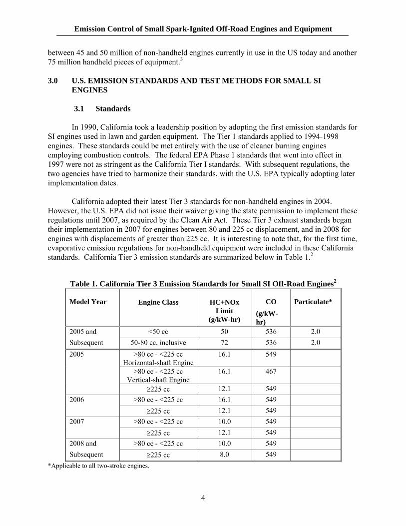
California adopted their latest Tier 3 standards for non-handheld engines in 2004.
However, the U.S. EPA did not issue their waiver giving the state permission to implement these regulations until 2007, as required by the Clean Air Act. These Tier 3 exhaust standards began their implementation in 2007 for engines between 80 and 225 cc displacement, and in 2008 for engines with displacements of greater than 225 cc. It is interesting to note that, for the first time, evaporative emission regulations for non-handheld equipment were included in these California standards. California Tier 3 emission standards are summarized below in Table 1.2
Table 1. California Tier 3 Emission Standards for Small SI Off-Road Engines2
Model Year
Engine Class
HC+NOx Limit
(g/kW-hr)
CO (g/kW-hr)
Particulate*
2005 and <50 cc 50 536 2.0 Subsequent 50-80 cc, inclusive 72 536 2.0 2005 >80 cc - <225 cc
Horizontal-shaft Engine16.1 549
>80 cc - <225 cc Vertical-shaft Engine
16.1 467
≥225 cc 12.1 549 2006 >80 cc - <225 cc 16.1 549 ≥225 cc 12.1 549 2007 >80 cc - <225 cc 10.0 549 ≥225 cc 12.1 549 2008 and >80 cc - <225 cc 10.0 549 Subsequent ≥225 cc 8.0 549
*Applicable to all two-stroke engines.
4
Emission Control of Small Spark-Ignited Off-Road Engines and Equipment
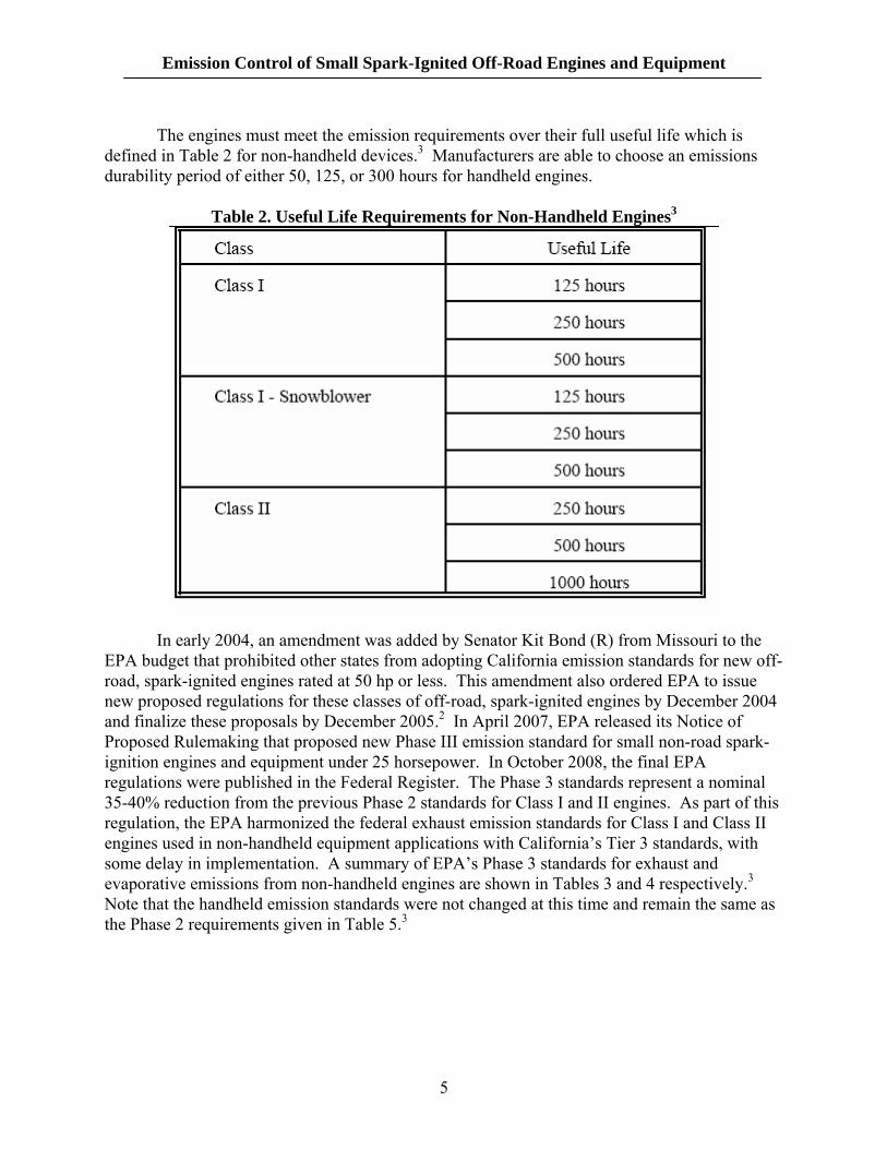
The engines must meet the emission requirements over their full useful life which is defined in Table 2 for non-handheld devices.3 Manufacturers are able to choose an emissions durability period of either 50, 125, or 300 hours for handheld engines.
Table 2. Useful Life Requirements for Non-Handheld Engines3
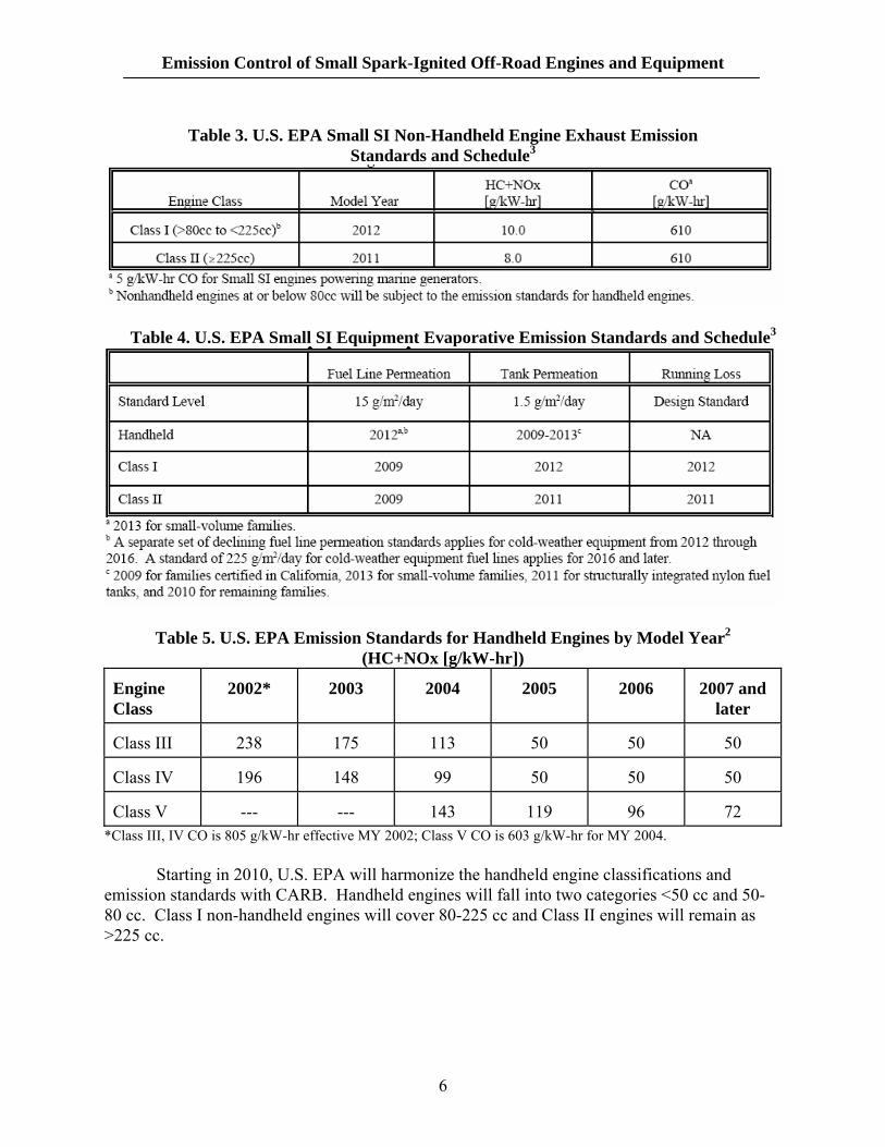
In early 2004, an amendment was added by Senator Kit Bond (R) from Missouri to the EPA budget that prohibited other states from adopting California emission standards for new off-road, spark-ignited engines rated at 50 hp or less. This amendment also ordered EPA to issue new proposed regulations for these classes of off-road, spark-ignited engines by December 2004 and finalize these proposals by December 2005.2 In April 2007, EPA released its Notice of Proposed Rulemaking that proposed new Phase III emission standard for small non-road spark-ignition engines and equipment under 25 horsepower. In October 2008, the final EPA regulations were published in the Federal Register. The Phase 3 standards represent a nominal 35-40% reduction from the previous Phase 2 standards for Class I and II engines. As part of this regulation, the EPA harmonized the federal exhaust emission standards for Class I and Class II engines used in non-handheld equipment applications with California’s Tier 3 standards, with some delay in implementation. A summary of EPA’s Phase 3 standards for exhaust and evaporative emissions from non-handheld engines are shown in Tables 3 and 4 respectively.3 Note that the handheld emission standards were not changed at this time and remain the same as the Phase 2 requirements given in Table 5.3
5
Emission Control of Small Spark-Ignited Off-Road Engines and Equipment
Table 3. U.S. EPA Small SI Non-Handheld Engine Exhaust Emission
Standards and Schedule3
Table 4. U.S. EPA Small SI Equipment Evaporative Emission Standards and Schedule3
Table 5. U.S. EPA Emission Standards for Handheld Engines by Model Year2
(HC+NOx [g/kW-hr]) Engine Class
2002*
2003
2004
2005
2006
2007 and
later Class III
238
175
113
50
50
50
Class IV
196
148
99
50
50
50
Class V
---
---
143
119
96
72
*Class III, IV CO is 805 g/kW-hr effective MY 2002; Class V CO is 603 g/kW-hr for MY 2004.
Starting in 2010, U.S. EPA will harmonize the handheld engine classifications and emission standards with CARB. Handheld engines will fall into two categories <50 cc and 50-80 cc. Class I non-handheld engines will cover 80-225 cc and Class II engines will remain as >225 cc.
6
Emission Control of Small Spark-Ignited Off-Road Engines and Equipment
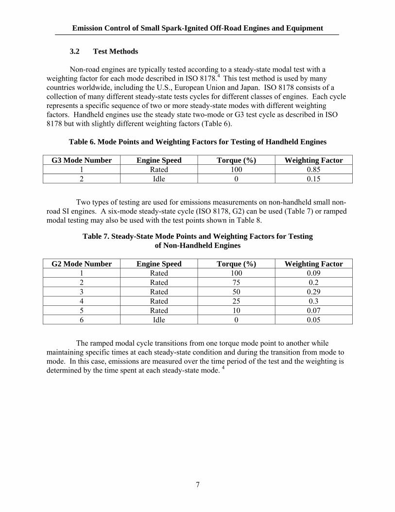
3.2 Test Methods Non-road engines are typically tested according to a steady-state modal test with a weighting factor for each mode described in ISO 8178.4 This test method is used by many countries worldwide, including the U.S., European Union and Japan. ISO 8178 consists of a collection of many different steady-state tests cycles for different classes of engines. Each cycle represents a specific sequence of two or more steady-state modes with different weighting factors. Handheld engines use the steady state two-mode or G3 test cycle as described in ISO 8178 but with slightly different weighting factors (Table 6).
Table 6. Mode Points and Weighting Factors for Testing of Handheld Engines
G3 Mode Number Engine Speed Torque (%) Weighting Factor 1 Rated 100 0.85 2 Idle 0 0.15
Two types of testing are used for emissions measurements on non-handheld small non-road SI engines. A six-mode steady-state cycle (ISO 8178, G2) can be used (Table 7) or ramped modal testing may also be used with the test points shown in Table 8.
Table 7. Steady-State Mode Points and Weighting Factors for Testing of Non-Handheld Engines
G2 Mode Number Engine Speed Torque (%) Weighting Factor
1 Rated 100 0.09 2 Rated 75 0.2 3 Rated 50 0.29 4 Rated 25 0.3 5 Rated 10 0.07 6 Idle 0 0.05
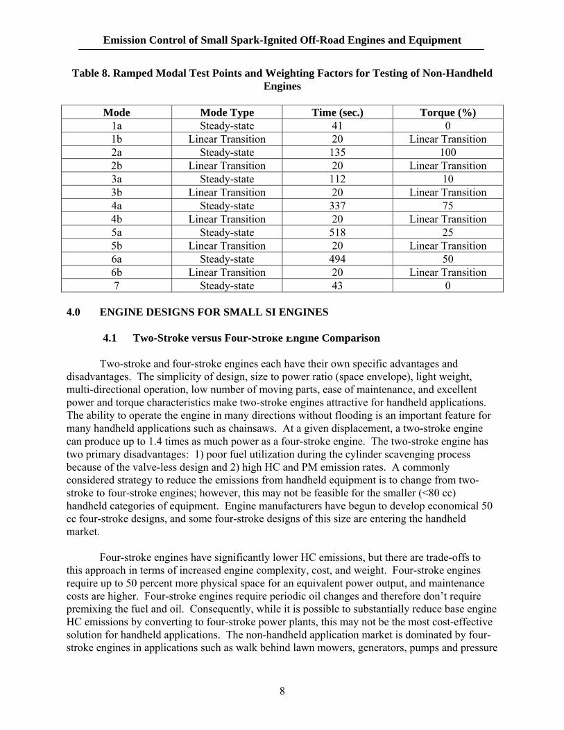
The ramped modal cycle transitions from one torque mode point to another while maintaining specific times at each steady-state condition and during the transition from mode to mode. In this case, emissions are measured over the time period of the test and the weighting is determined by the time spent at each steady-state mode. 4
7
Emission Control of Small Spark-Ignited Off-Road Engines and Equipment
Table 8. Ramped Modal Test Points and Weighting Factors for Testing of Non-Handheld Engines
Mode Mode Type Time (sec.) Torque (%)
1a Steady-state 41 0 1b Linear Transition 20 Linear Transition 2a Steady-state 135 100 2b Linear Transition 20 Linear Transition 3a Steady-state 112 10 3b Linear Transition 20 Linear Transition 4a Steady-state 337 75 4b Linear Transition 20 Linear Transition 5a Steady-state 518 25 5b Linear Transition 20 Linear Transition 6a Steady-state 494 50 6b Linear Transition 20 Linear Transition 7 Steady-state 43 0
4.0 ENGINE DESIGNS FOR SMALL SI ENGINES 4.1 Two-Stroke versus Four-Stroke Engine Comparison
Two-stroke and four-stroke engines each have their own specific advantages and disadvantages. The simplicity of design, size to power ratio (space envelope), light weight, multi-directional operation, low number of moving parts, ease of maintenance, and excellent power and torque characteristics make two-stroke engines attractive for handheld applications. The ability to operate the engine in many directions without flooding is an important feature for many handheld applications such as chainsaws. At a given displacement, a two-stroke engine can produce up to 1.4 times as much power as a four-stroke engine. The two-stroke engine has two primary disadvantages: 1) poor fuel utilization during the cylinder scavenging process because of the valve-less design and 2) high HC and PM emission rates. A commonly considered strategy to reduce the emissions from handheld equipment is to change from two-stroke to four-stroke engines; however, this may not be feasible for the smaller (<80 cc) handheld categories of equipment. Engine manufacturers have begun to develop economical 50 cc four-stroke designs, and some four-stroke designs of this size are entering the handheld market.
Four-stroke engines have significantly lower HC emissions, but there are trade-offs to this approach in terms of increased engine complexity, cost, and weight. Four-stroke engines require up to 50 percent more physical space for an equivalent power output, and maintenance costs are higher. Four-stroke engines require periodic oil changes and therefore don’t require premixing the fuel and oil. Consequently, while it is possible to substantially reduce base engine HC emissions by converting to four-stroke power plants, this may not be the most cost-effective solution for handheld applications. The non-handheld application market is dominated by four-stroke engines in applications such as walk behind lawn mowers, generators, pumps and pressure
8
Emission Control of Small Spark-Ignited Off-Road Engines and Equipment
washers. These small four-stroke engines typically employ integral exhaust and fuel systems. The differences between the combustion processes in two- and four-stroke engine designs will be detailed below.
4.2 Two-Stroke Engines
The primary emissions from a two-stroke engine are HCs, CO, and particulate matter
(PM) emissions in the form of white smoke. NOx emissions are typically very low for two-stroke engines because of the effect of high residual combustion gas retained in the combustion chamber which acts as internal exhaust gas recirculation or EGR. NOx emissions are not regarded as a significant issue for two-stroke engine vehicles. A two-stroke engine relies on the pressurized flow of the compressed intake charge to force combustion products out of the cylinder. Because intake and exhaust gases are entering and leaving the cylinder simultaneously, this results in a portion of the intake charge escaping through the exhaust port without being combusted. The simplest two-stroke designs rely on a carbureted air/fuel intake charge and therefore 15 to 40% of the escaping charge is unburned fuel. These so-called scavenging emissions result in high emissions of HC and increased consumption of fuel compared to four-stroke engines.5 Due to the lubrication technology used on the basic two-stroke engines, scavenging also results in high PM emissions. Two-stroke engines compress the intake charge during the power stroke of the piston. Piston rings cannot serve as efficient lubricating system seals in a two-stroke engine since the intake, transfer, and exhaust ports all penetrate the cylinder wall. Therefore, two-stroke engines generally rely on “total loss” lubricating systems, where oil is mixed with the fuel or introduced into the fuel-air mixture and consumed during the combustion process. A portion of the lubricating oil is exhausted without being combusted during the scavenging process and represents the bulk of PM emissions from two-stroke engines. It is estimated that unburned lubricating oil comprises 80 to 95% of total two-stroke PM emissions. Depending on the specific fuel-to-oil mixing ratio that was used, unburned oil is often exhibited by the white smoke emissions that are common from two-stroke engines.5
4.3 Four-Stroke Engines
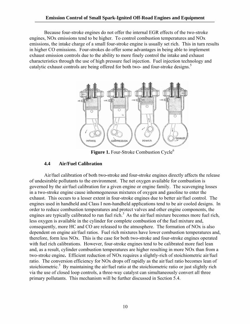
Due to their larger size, four-stroke engines are used in virtually all Class I and II non-handheld engines. Four-stroke engines require two piston cycles for every combustion cycle (Figure 1). Therefore, for engines running at the same speed, a four-stroke engine will produce half the work as a two-stroke engine. However, four-stroke engines provide greater combustion control as each of the four combustion strokes occur during a distinct movement of the piston through the cylinder. The four strokes consist of intake, compression, combustion, and exhaust. This effectively separates the exhaust and intake strokes of the combustion cycle and controls the scavenging losses. As a result, both HC emissions and fuel consumption are reduced relative to two-stroke engines. Four-stroke engines in Class I applications are air-cooled and therefore have higher HC and NOx emissions than water-cooled engines.5
9
Emission Control of Small Spark-Ignited Off-Road Engines and Equipment
Because four-stroke engines do not offer the internal EGR effects of the two-stroke engines, NOx emissions tend to be higher. To control combustion temperatures and NOx emissions, the intake charge of a small four-stroke engine is usually set rich. This in turn results in higher CO emissions. Four-strokes do offer some advantages in being able to implement exhaust emission controls due to the ability to more finely control the intake and exhaust characteristics through the use of high pressure fuel injection. Fuel injection technology and catalytic exhaust controls are being offered for both two- and four-stroke designs.5
Figure 1. Four-Stroke Combustion Cycle6
4.4 Air/Fuel Calibration
Air/fuel calibration of both two-stroke and four-stroke engines directly affects the release of undesirable pollutants to the environment. The net oxygen available for combustion is governed by the air/fuel calibration for a given engine or engine family. The scavenging losses in a two-stroke engine cause inhomogeneous mixtures of oxygen and gasoline to enter the exhaust. This occurs to a lesser extent in four-stroke engines due to better air/fuel control. The engines used in handheld and Class I non-handheld applications tend to be air cooled designs. In order to reduce combustion temperatures and protect valves and other engine components, the engines are typically calibrated to run fuel rich.3 As the air/fuel mixture becomes more fuel rich, less oxygen is available in the cylinder for complete combustion of the fuel mixture and, consequently, more HC and CO are released to the atmosphere. The formation of NOx is also dependent on engine air/fuel ratios. Fuel rich mixtures have lower combustion temperatures and, therefore, form less NOx. This is the case for both two-stroke and four-stroke engines operated with fuel rich calibrations. However, four-stroke engines tend to be calibrated more fuel lean and, as a result, cylinder combustion temperatures are higher resulting in more NOx than from a two-stroke engine. Efficient reduction of NOx requires a slightly-rich of stoichiometric air/fuel ratio. The conversion efficiency for NOx drops off rapidly as the air/fuel ratio becomes lean of stoichiometric.5 By maintaining the air/fuel ratio at the stoichiometric ratio or just slightly rich via the use of closed loop controls, a three-way catalyst can simultaneously convert all three primary pollutants. This mechanism will be further discussed in Section 5.4.
10
Emission Control of Small Spark-Ignited Off-Road Engines and Equipment
Enleanment of the air-fuel mixture is a common approach to reducing HC emissions by achieving a more complete combustion. This approach also results in increased combustion temperatures and places a practical limit to how far it may be employed. This approach may also be effectively applied to lean out the exhaust by increasing the amount of oxygen in the exhaust in post-combustion prior to the catalyst. This approach known as secondary air injection will be discussed later in Section 5.3. 5.0 EMISSION CONTROL TECHNOLOGIES FOR SMALL SI ENGINES
5.1 Engine Combustion Controls
The first approach to reducing emissions from any engine focuses on optimizing the combustion process. Costs are an important factor in the application of two-stroke engines and therefore, the cost of improvements must be weighed against the cost of a four-stroke engine.
The obvious focus for reducing emissions from two-stroke engines must consider reduction in scavenging loses. The approaches that have been considered, attempt to separate the air and fuel intake strategies by using air to accomplish stratified scavenging. This approach also effectively leans out the air-fuel mixture thus improving combustion efficiency. Further improvements have pressurized air/fuel mixtures prior to the combustion chamber. This has demonstrated improved mixing of reactants upon entering the cylinder. PM reductions can be achieved by not mixing lubricating oil with the fuel. Another approach may be to incorporate direct injection to introduce fuel directly into the combustion chamber once the exhaust port is closed.5 This approach is primarily reserved for the larger two-stroke engine designs and is not common in Class I and II engines.
There has also been substantial research into reducing the cost and improving engine performance of four-stroke engines. Smaller Class I four stroke engines have either overhead valve or the more common side-valve technology.2 The side-valve designs allow higher amounts of lubricating oil to pass into the exhaust which must be addressed when incorporating catalysts. Some advanced four-stroke technologies combine the benefits of four and two-stroke designs by using a fuel-oil mixture to reduce the engine size by eliminating the oil storage and delivery system and facilitate multi-positional operation in handheld applications. Because the basic engine operation is a four-stroke it is possible to reduce HC emissions by eliminating scavenging losses. Another advanced design combines a pressurized pre-mix chamber together with a fuel-oil mixture in a four stroke engine. Incorporation of fuel injection (FI) to four-stroke engines does offer significant air to fuel ratio control advantages over the more common carbureted designs. Rather than injecting directly into the combustion chamber, as in the case of direct injection (DI), FI technology typically injects fuel into the cylinder intake port to allow additional time for vaporization. This also allows the use of lower pressure injectors thus reducing costs. Fuel injection technology has demonstrated 40% reduction in HC, 80% reduction in CO and a 50% increase in NOx over carbureted four-stroke engines.5 The better fuel control results in approximately 20% improved fuel efficiency and corresponding reductions in CO2. The cost of fuel injection technology has limited applications primarily to larger Class II engines. Other engine improvements that would
11
Emission Control of Small Spark-Ignited Off-Road Engines and Equipment
benefit this class of engine include improved cooling system designs and electronic controls for the larger multi-cylinder engines.3
5.2 Evaporative Emission Controls
The purpose of evaporative emissions systems is to reduce or eliminate the release of vaporized HC and VOCs into the atmosphere. These systems have been used on automobiles since the 1960s in the form of PCV or positive crankcase ventilation valves. Evaporative emission control systems on cars have increased in complexity over the years and have recently been applied to motorcycles. The California Tier 3 and Federal Phase 3 emission standards include permeation limits for the <80 cc engine categories as well as diurnal emission standards for the larger Class I and II engines (>80 cc) The HC vapors and VOCs react in the atmosphere and contribute to the formation of photochemical smog. Reaction of these pollutants with NOx in the presence of sunlight leads to ozone formation.
The major source of these emissions is from the fuel system and therefore it is not surprising that fuel injection technology provides significant evaporative emissions benefits. Fuel injection systems effectively eliminate the vaporization of fuel from open carburetors. Other significant sources of evaporative emissions from the fuel system include fuel permeation from the fuel tank and fuel delivery hoses. Types of evaporative emissions are classified into five categories:
• Diurnal: This represents gasoline that evaporates due to the rise in ambient temperature.
• Running losses: Represent gasoline that vaporizes due to the heat of the engine and exhaust system during normal operation.
• Resting losses: Natural permeation that occurs from the fuel delivery system while not operating under ambient conditions.
• Hot Soak: Vaporization of fuel due to the retained heat of the engine after the engine is turned off.
• Refueling: Represents the fuel vapors that escape from the tank by the displacement of liquid fuel.
Evaporative emissions are measured using a sealed housing for evaporative
determination (SHED) apparatus over the course of a multi-day Federal Test Procedure (FTP) to quantify all of the various forms of evaporative emissions. This testing is generally most effective in determining diurnal and hot soak emissions.5
Permeation emissions are reduced by the use of low permeation hoses and fuel tanks
made of nylon or specially treated polymers. Low permeation fuel lines may combine a thermoplastic barrier layer in between two rubber layers. Plastic fuel tanks used in small SI applications can be molded by a number of different processes to incorporate similar barrier layers into the plastic sheet that is used to form the fuel tank. Permeation barriers may be introduced through a post processing step through a process known as fluorination or sulfonation. In these steps, a gas is introduced into the tank to form a low permeation surface
12
Emission Control of Small Spark-Ignited Off-Road Engines and Equipment
layer. Plastic tanks are well suited for handheld equipment due to the lighter weight while many fuel tanks on Class I and II engines are metal and exhibit no permeation.3
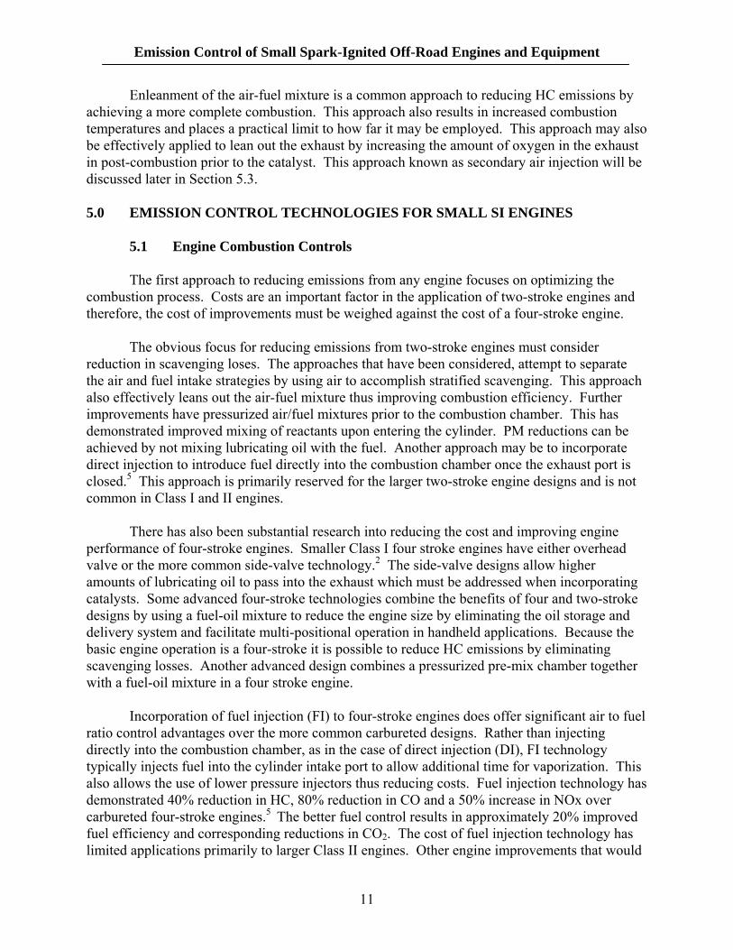
Diurnal emissions are captured by high surface area activated carbon contained in
canisters connected to the fuel system. The captured HC vapors are then recycled back to the intake of the engine to be combusted (Figure 2). The carbon is a high surface area pelletized material that adsorbs fuel vapors via loose chemical bonds and releases them in a controlled fashion via purging the vapors with air flow. The purging in small SI engines is achieved by the natural breathing of the fuel tank as it heats and cools.3 A vented fuel cap serves to allow air to enter as fuel is depleted while venting expanded vapors in the fuel tank into the carbon canister. In a similar fashion, running loss emissions can be controlled by sealing the fuel cap and routing vapors into the engine intake where they are combusted.
Figure 2. Carbon canister used to capture evaporative emissions on small SI engines.
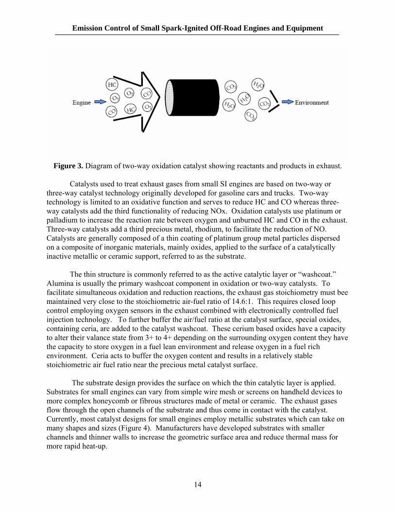
5.3 General Overview of Catalyst Technology Catalytic technology uses a catalyst to assist in chemical reactions to convert the harmful
components of the engine’s exhaust stream to harmless gases. The catalyst performs this function without being changed or consumed by the reactions that take place. In particular, the catalyst, when installed in the exhaust stream, promotes the reaction of HC and CO with oxygen to form carbon dioxide and water. The chemical reduction of NOx to nitrogen is caused by reaction with CO over a suitable catalyst. The role of the catalyst in promoting these beneficial reactions is depicted in Figure 3.
13
Emission Control of Small Spark-Ignited Off-Road Engines and Equipment
Figure 3. Diagram of two-way oxidation catalyst showing reactants and products in exhaust.
Catalysts used to treat exhaust gases from small SI engines are based on two-way or
three-way catalyst technology originally developed for gasoline cars and trucks. Two-way technology is limited to an oxidative function and serves to reduce HC and CO whereas three-way catalysts add the third functionality of reducing NOx. Oxidation catalysts use platinum or palladium to increase the reaction rate between oxygen and unburned HC and CO in the exhaust. Three-way catalysts add a third precious metal, rhodium, to facilitate the reduction of NO. Catalysts are generally composed of a thin coating of platinum group metal particles dispersed on a composite of inorganic materials, mainly oxides, applied to the surface of a catalytically inactive metallic or ceramic support, referred to as the substrate.
The thin structure is commonly referred to as the active catalytic layer or “washcoat.” Alumina is usually the primary washcoat component in oxidation or two-way catalysts. To facilitate simultaneous oxidation and reduction reactions, the exhaust gas stoichiometry must bee maintained very close to the stoichiometric air-fuel ratio of 14.6:1. This requires closed loop control employing oxygen sensors in the exhaust combined with electronically controlled fuel injection technology. To further buffer the air/fuel ratio at the catalyst surface, special oxides, containing ceria, are added to the catalyst washcoat. These cerium based oxides have a capacity to alter their valance state from 3+ to 4+ depending on the surrounding oxygen content they have the capacity to store oxygen in a fuel lean environment and release oxygen in a fuel rich environment. Ceria acts to buffer the oxygen content and results in a relatively stable stoichiometric air fuel ratio near the precious metal catalyst surface.
The substrate design provides the surface on which the thin catalytic layer is applied.
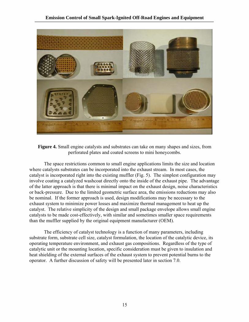
Substrates for small engines can vary from simple wire mesh or screens on handheld devices to more complex honeycomb or fibrous structures made of metal or ceramic. The exhaust gases flow through the open channels of the substrate and thus come in contact with the catalyst. Currently, most catalyst designs for small engines employ metallic substrates which can take on many shapes and sizes (Figure 4). Manufacturers have developed substrates with smaller channels and thinner walls to increase the geometric surface area and reduce thermal mass for more rapid heat-up.
14
Emission Control of Small Spark-Ignited Off-Road Engines and Equipment
Figure 4. Small engine catalysts and substrates can take on many shapes and sizes, from perforated plates and coated screens to mini honeycombs.
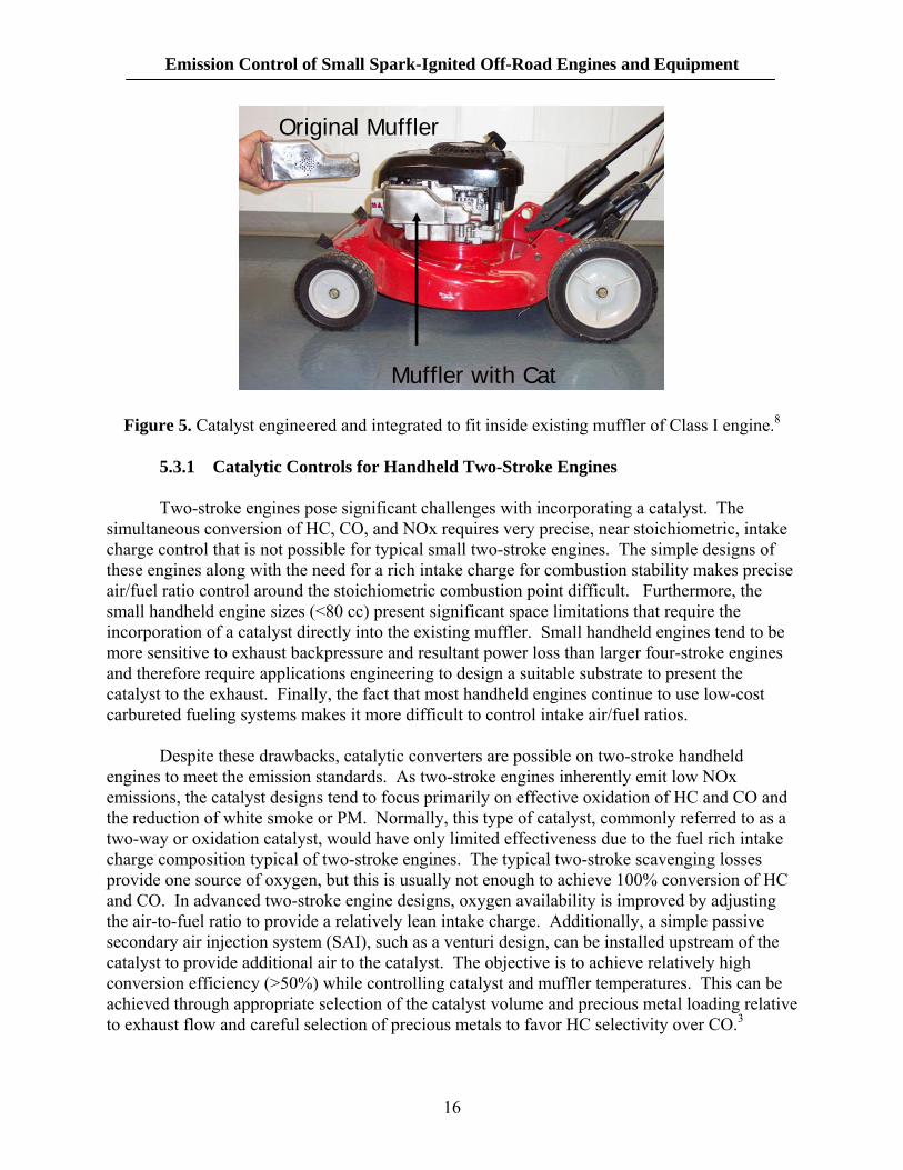
The space restrictions common to small engine applications limits the size and location
where catalysts substrates can be incorporated into the exhaust stream. In most cases, the catalyst is incorporated right into the existing muffler (Fig. 5). The simplest configuration may involve coating a catalyzed washcoat directly onto the inside of the exhaust pipe. The advantage of the latter approach is that there is minimal impact on the exhaust design, noise characteristics or back-pressure. Due to the limited geometric surface area, the emissions reductions may also be nominal. If the former approach is used, design modifications may be necessary to the exhaust system to minimize power losses and maximize thermal management to heat up the catalyst. The relative simplicity of the design and small package envelope allows small engine catalysts to be made cost-effectively, with similar and sometimes smaller space requirements than the muffler supplied by the original equipment manufacturer (OEM).
The efficiency of catalyst technology is a function of many parameters, including
substrate form, substrate cell size, catalyst formulation, the location of the catalytic device, its operating temperature environment, and exhaust gas compositions. Regardless of the type of catalytic unit or the mounting location, specific consideration must be given to insulation and heat shielding of the external surfaces of the exhaust system to prevent potential burns to the operator. A further discussion of safety will be presented later in section 7.0.
15
Emission Control of Small Spark-Ignited Off-Road Engines and Equipment
Original Muffler
Muffler with Cat
Figure 5. Catalyst engineered and integrated to fit inside existing muffler of Class I engine.8
5.3.1 Catalytic Controls for Handheld Two-Stroke Engines Two-stroke engines pose significant challenges with incorporating a catalyst. The simultaneous conversion of HC, CO, and NOx requires very precise, near stoichiometric, intake charge control that is not possible for typical small two-stroke engines. The simple designs of these engines along with the need for a rich intake charge for combustion stability makes precise air/fuel ratio control around the stoichiometric combustion point difficult. Furthermore, the small handheld engine sizes (<80 cc) present significant space limitations that require the incorporation of a catalyst directly into the existing muffler. Small handheld engines tend to be more sensitive to exhaust backpressure and resultant power loss than larger four-stroke engines and therefore require applications engineering to design a suitable substrate to present the catalyst to the exhaust. Finally, the fact that most handheld engines continue to use low-cost carbureted fueling systems makes it more difficult to control intake air/fuel ratios.
Despite these drawbacks, catalytic converters are possible on two-stroke handheld engines to meet the emission standards. As two-stroke engines inherently emit low NOx emissions, the catalyst designs tend to focus primarily on effective oxidation of HC and CO and the reduction of white smoke or PM. Normally, this type of catalyst, commonly referred to as a two-way or oxidation catalyst, would have only limited effectiveness due to the fuel rich intake charge composition typical of two-stroke engines. The typical two-stroke scavenging losses provide one source of oxygen, but this is usually not enough to achieve 100% conversion of HC and CO. In advanced two-stroke engine designs, oxygen availability is improved by adjusting the air-to-fuel ratio to provide a relatively lean intake charge. Additionally, a simple passive secondary air injection system (SAI), such as a venturi design, can be installed upstream of the catalyst to provide additional air to the catalyst. The objective is to achieve relatively high conversion efficiency (>50%) while controlling catalyst and muffler temperatures. This can be achieved through appropriate selection of the catalyst volume and precious metal loading relative to exhaust flow and careful selection of precious metals to favor HC selectivity over CO.3
16
Emission Control of Small Spark-Ignited Off-Road Engines and Equipment
Another beneficial use of catalyst technology on two-stroke engines is the reduction of white smoke (particulate matter). It is estimated that conversion efficiencies of an oxidation catalyst on a two-stroke engine are on the order of 50% for HC, 50% for CO, and 45% for PM without the use of secondary air. The addition of secondary air injection is estimated to increase average conversion efficiencies to approximately 80% for HC, 75% for CO, and 70% for PM.5
The implementation of two-way catalysts to small handheld two-stroke engines is well known and commercially demonstrated technology on millions of handheld devices every year. The relatively small size and simple design of these catalysts allows them to be incorporated directly into existing mufflers with minimal modifications to the interior design making them extremely cost effective and durable approaches to reducing emissions. Catalyst and muffler design issues, such as heat management, packaging, poisoning, and durability, are straight-forward engineering challenges that are well understood and readily employed through a systems approach involving the engine manufacturer working together with the catalyst supplier.
5.3.2 Catalytic Controls for Class I and Class II Four-Stroke Engines
Class I four-stroke engines, such as those employed in walk-behind lawnmowers, will often employ similar approaches to control emissions as those discussed for two-stroke engines. Oxidation catalysts on four-stroke engines can provide substantially higher emission reductions of HC than on two-stroke engines. Oxidation catalysts in combination with secondary air are capable of achieving reductions of 80% for HC and 90% for CO, with a corresponding increase of 35% in CO2 emissions due to the conversion of HC and CO emissions to CO2. The lower engine-out HC of four-stroke engines and higher exhaust temperatures results in lower exotherms and faster light-off of the catalyst, thus extending catalyst life. The rich air/fuel calibration of air cooled four-stroke engines may limit the availability of oxygen for post-combustion oxidation of HC and CO and therefore small four-stroke engines may use a secondary air injection system upstream of the catalyst. In the smaller Class I engines, one must employ similar approaches to catalyst selection as discussed for two-stroke engines previously. These include methods such as appropriate catalyst sizing and precious metal selection that favors HC over CO oxidation and minimizing NOx through fuel rich combustion atmospheres.
Sometimes unique solutions must be applied in side valve engines to increase catalyst
durability and meet tighter useful life emission standards. These solutions may rely on a two catalyst design where the upstream catalyst catches the oil in the exhaust typical of these engines thus limiting catalyst poisoning of the downstream catalyst. Another approach may employ a single, slightly longer catalyst where the upstream part of the catalyst is sacrificed by allowing some degree of poisoning leaving the downstream part to allow conversion for the full life of the engine.
The larger Class II engines such as those used on lawn tractors offer more flexibility in the use of combustion controls to limit engine-out emissions combined with advanced three-way catalysts (TWCs). Unlike Class I engines, Class II designs don’t typically have integral fuel systems and exhaust components. These engines typically have overhead valves and are air cooled. In some cases, these larger engines employ active cooling systems. Most Class II engines employ more advanced fuel metering and spark controls than the typical Class I engine.
17
Emission Control of Small Spark-Ignited Off-Road Engines and Equipment
They are for the most part carbureted engines with lower CO emissions than Class I engines. One converter manufacturer has developed a unique multi-chamber airflow design that allows the exhaust to pass over the catalyst multiple times as opposed to the conventional single pass design. This facilitates better heat and pressure distribution resulting in a more efficient catalyst at reducing emissions and a more durable product.
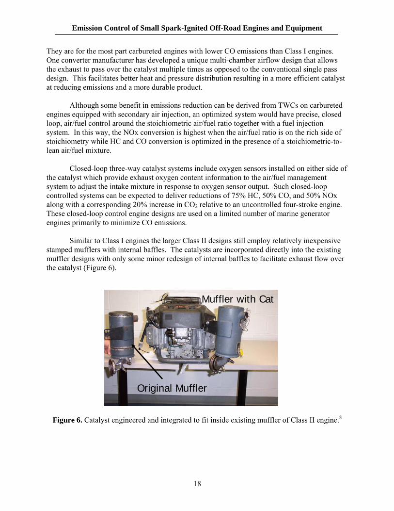
Although some benefit in emissions reduction can be derived from TWCs on carbureted engines equipped with secondary air injection, an optimized system would have precise, closed loop, air/fuel control around the stoichiometric air/fuel ratio together with a fuel injection system. In this way, the NOx conversion is highest when the air/fuel ratio is on the rich side of stoichiometry while HC and CO conversion is optimized in the presence of a stoichiometric-to-lean air/fuel mixture. Closed-loop three-way catalyst systems include oxygen sensors installed on either side of the catalyst which provide exhaust oxygen content information to the air/fuel management system to adjust the intake mixture in response to oxygen sensor output. Such closed-loop controlled systems can be expected to deliver reductions of 75% HC, 50% CO, and 50% NOx along with a corresponding 20% increase in CO2 relative to an uncontrolled four-stroke engine. These closed-loop control engine designs are used on a limited number of marine generator engines primarily to minimize CO emissions. Similar to Class I engines the larger Class II designs still employ relatively inexpensive stamped mufflers with internal baffles. The catalysts are incorporated directly into the existing muffler designs with only some minor redesign of internal baffles to facilitate exhaust flow over the catalyst (Figure 6).
Muffler with Cat
Original Muffler
Figure 6. Catalyst engineered and integrated to fit inside existing muffler of Class II engine.8
18
Emission Control of Small Spark-Ignited Off-Road Engines and Equipment
Catalyst volumes relative to engine displacement are controlled as is precious metal loading to control surface temperatures within safe ranges. Incorporation of passive secondary air helps to reduce the necessary catalyst volume. Because these larger Class II engines often come with 12 volt DC electric systems, they may be able to employ active, pump driven air injection systems. The relatively low catalyst precious metal loadings maintain the high level of cost effectiveness of exhaust emission controls. The precious metal ratios in these applications would tend to favor HC and NOx selectivity over CO. 6.0 DEMONSTRATION PROGRAMS Prior to the release of its staff proposal for the Tier 3 emission standards for small SI engines, the California Air resources Board sponsored a demonstration program at Southwest Research Institute to evaluate the feasibility of reducing engine-out emissions and employing catalysts on two Class I engines.4 This program employed simple engine combustion controls to enlean the exhaust during low-load operation and protect the engines during high-load test modes via rich burn conditions. Early generations of catalyst systems were also included in this study. They did observe engine deterioration of both the engine and catalysts over time resulting in an increase of exhaust emissions.7
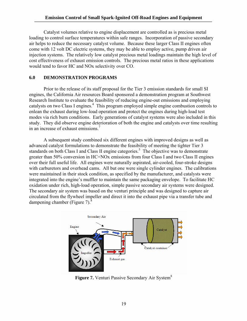
A subsequent study combined six different engines with improved designs as well as advanced catalyst formulations to demonstrate the feasibility of meeting the tighter Tier 3 standards on both Class I and Class II engine categories.5 The objective was to demonstrate greater than 50% conversion in HC+NOx emissions from four Class I and two Class II engines over their full useful life. All engines were naturally aspirated, air-cooled, four-stroke designs with carburetors and overhead cams. All but one were single cylinder engines. The calibrations were maintained in their stock condition, as specified by the manufacturer, and catalysts were integrated into the engine’s muffler to maintain the same packaging envelope. To facilitate HC oxidation under rich, high-load operation, simple passive secondary air systems were designed. The secondary air system was based on the venturi principle and was designed to capture air circulated from the flywheel impeller and direct it into the exhaust pipe via a transfer tube and dampening chamber (Figure 7).8
Figure 7. Venturi Passive Secondary Air System8
19
Emission Control of Small Spark-Ignited Off-Road Engines and Equipment
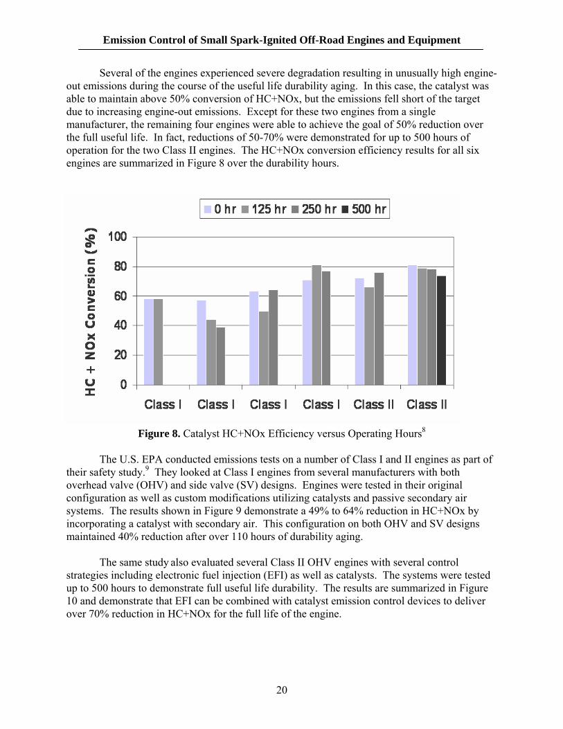
Several of the engines experienced severe degradation resulting in unusually high engine-out emissions during the course of the useful life durability aging. In this case, the catalyst was able to maintain above 50% conversion of HC+NOx, but the emissions fell short of the target due to increasing engine-out emissions. Except for these two engines from a single manufacturer, the remaining four engines were able to achieve the goal of 50% reduction over the full useful life. In fact, reductions of 50-70% were demonstrated for up to 500 hours of operation for the two Class II engines. The HC+NOx conversion efficiency results for all six engines are summarized in Figure 8 over the durability hours.
Figure 8. Catalyst HC+NOx Efficiency versus Operating Hours8
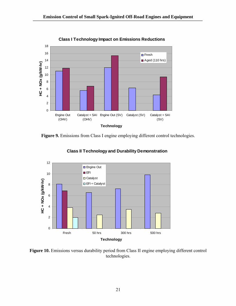
The U.S. EPA conducted emissions tests on a number of Class I and II engines as part of their safety study.9 They looked at Class I engines from several manufacturers with both overhead valve (OHV) and side valve (SV) designs. Engines were tested in their original configuration as well as custom modifications utilizing catalysts and passive secondary air systems. The results shown in Figure 9 demonstrate a 49% to 64% reduction in HC+NOx by incorporating a catalyst with secondary air. This configuration on both OHV and SV designs maintained 40% reduction after over 110 hours of durability aging.
The same study also evaluated several Class II OHV engines with several control strategies including electronic fuel injection (EFI) as well as catalysts. The systems were tested up to 500 hours to demonstrate full useful life durability. The results are summarized in Figure 10 and demonstrate that EFI can be combined with catalyst emission control devices to deliver over 70% reduction in HC+NOx for the full life of the engine.
20
Emission Control of Small Spark-Ignited Off-Road Engines and Equipment
Class I Technology Impact on Emissions Reductions
0
2
4
6
8
10
12
14
16
18
Engine Out(OHV)
Catalyst + SAI(OHV)
Engine Out (SV) Catalyst (SV) Catalyst + SAI(SV)
Technology
HC +
NO
x (g
/kW
-hr)
Fresh
Aged (110 hrs)
Figure 9. Emissions from Class I engine employing different control technologies.
Class II Technology and Durability Demonstration
0
2
4
6
8
10
12
Fresh 50 hrs 300 hrs 500 hrs
Technology
HC +
NO
x (g
/kW
-hr)
Engine Out
EFI
Catalyst
EFI + Catalyst
Figure 10. Emissions versus durability period from Class II engine employing different control
technologies.
21
Emission Control of Small Spark-Ignited Off-Road Engines and Equipment
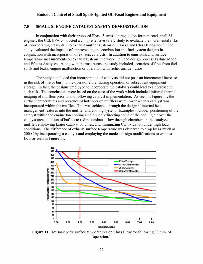
7.0 SMALL SI ENGINE CATALYST SAFETY DEMONSTRATION In conjunction with their proposed Phase 3 emission regulation for non-road small SI engines, the U.S. EPA conducted a comprehensive safety study to evaluate the incremental risks of incorporating catalysts into exhaust muffler systems on Class I and Class II engines.9 The study evaluated the impacts of improved engine combustion and fuel system designs in conjunction with incorporation of exhaust catalysts. In addition to emissions and surface temperature measurements on exhaust systems, the work included design process Failure Mode and Effects Analyses. Along with thermal burns, the study included scenarios of fires from fuel spills and leaks, engine malfunction or operation with richer air/fuel ratios. The study concluded that incorporation of catalysts did not pose an incremental increase in the risk of fire or burn to the operator either during operation or subsequent equipment storage. In fact, the designs employed to incorporate the catalysts could lead to a decrease in such risk. The conclusions were based on the core of the work which included infrared thermal imaging of mufflers prior to and following catalyst implementation. As seen in Figure 11, the surface temperatures and presence of hot spots on mufflers were lower when a catalyst was incorporated within the muffler. This was achieved through the design if internal heat management features into the muffler and cooling system. Examples include: positioning of the catalyst within the engine fan cooling air flow or redirecting some of the cooling air over the catalyst area, addition of baffles to redirect exhaust flow through chambers in the catalyzed muffler, employing larger catalyst volumes, and minimizing CO oxidation under high load conditions. The difference of exhaust surface temperature was observed to drop by as much as 200ºC by incorporating a catalyst and employing the modest design modifications to exhaust flow as seen in Figure 11.
Figure 11. Hot soak peak surface temperatures on Class II tractor following 30 min. of
operation.9
22

Emission Control of Small Spark-Ignited Off-Road Engines and Equipment
The safety study concluded that the catalyzed systems posed no incremental increase in risk of thermal burns or fires over the OEM designed exhaust mufflers that did not include catalysts.9
23
Emission Control of Small Spark-Ignited Off-Road Engines and Equipment
8.0 CONCLUSION
• As other mobile sources of emissions get cleaned up, the off-road small spark-ignited engines used on lawn equipment, generators and compressors are projected to almost double by 2030 to over 26% of mobile VOC+NOx.
• The United States and Europe have been tightening their emission regulation for
small non-road engines over the past several years. The most recent California ARB Tier 3 and U.S. EPA Phase 3 regulations and standards require engine improvements and on some categories of small engines will most likely require the use of advanced catalyst technology.
• Catalyst technology has clearly demonstrated the ability to achieve significant
emissions reductions from both two-stroke and four-stroke small SI engines used on handheld and non-handheld applications.
• Unleaded fuel must be available in markets where catalyst technology is employed.
In those areas where leaded and unleaded fuels are available, care must be taken to avoid mis-fueling.
• The smaller two-stroke handheld engines and some small non-handheld engines can
comply with stringent hydrocarbon and carbon monoxide emissions standards by using oxidation catalyst technology, which, in addition, removes a high percentage of particulate emissions.
• Conventional two-way or three-way catalysts can be cost-effectively installed directly
into existing, small engine mufflers. Numerous demonstration programs have demonstrated the efficacy and safe implementation of catalyst emission control technology on this category of spark-ignited engines.
• To comply with tighter evaporative emission standards, the larger category of Class II
small engines must take advantage of low permeation fuel systems, including low permeation hose and tank materials in addition to employing conventional passive purge systems such as carbon canisters.
24
Emission Control of Small Spark-Ignited Off-Road Engines and Equipment
9.0 REFERENCES 1. “U.S. EPA 2007 Progress Report on Vehicle and Engine Compliance Activities,” November
2008. 2. California Air Resources Board, “Staff Report Initial Statement of Reasons for Proposed
Rulemaking for Exhaust and Evaporative Emission Control Requirements for Small Off-Road Equipment and Engines ≤19 kW,” August 8, 2003.
3. U.S. EPA Final Regulatory Impact Analysis, “Control of Emissions from Marine SI and
Small SI Engines, Vessels, and Equipment,” EPA420-R-08-014, September 2008. 4. www.dieselnet.com 5. MECA White Paper, “Emission Control of Two and Three-Wheeled Vehicles,”
www.meca.org, August 2008. 6. www.carbasics-1950.com 7. Southwest Research Institute, ARB Contract No. 96-603, “Development and Testing of
Clean Utility and Lawn and Garden Equipment,” July 1998. 8. Southwest Research Institute, SwRI Project No. 08.05734, “Durability of Lower-Emissions
Small Off-Road Engines,” C.C. Lela and J.J. White prepared for California Air Resources Board, Final Report, April 2004.
9. “EPA Technical Study on the Safety of Emission Controls for Nonroad Spark-Ignition
Engines <50 Horsepower,” EPA420-R-06-006, March 2006.
25