emergent form from structural optimisation of the voronoi ...discovery.ucl.ac.uk/5077/1/5077.pdf ·...
TRANSCRIPT
Emergent Form from Structural Optimisation of the VoronoiPolyhedra Structure
E. Friedrich, Dipl.Ing, C. Derix, MSc, S. Hanna, MScBartlett School of Graduate Studies, University College London, London WC1E 6BT
School of Architecture and Visual Arts, University of East London
e-mail:[email protected]
[email protected]@ucl.ac.uk
Abstract
In the course of the exploration of computational means in the architectural design process, inorder to investigate more complex, adaptive geometries, the Voronoi diagram has recentlygained some attention, being a three-dimensional space-filling structure which is modular butnot repetitive. The project looks at the Voronoi diagram as a load-bearing structure, andwhether it can be useful for structural optimisation. Hereby the edges of the Voronoipolyhedra are regarded as structural members of a statical system, which then is assessed bystructural analysis software. Results seem to indicate that the Voronoi approach produces avery specific structural as well as spatial type of order. Through the dislocation of the Voronoicells, the statical structure becomes more complex through emergent topology changes, andthe initially simple spatial system becomes much more complex through emergingadjacencies and interconnections between spaces. The characteristics of the emerging form,however, lie rather in the complexity how shifted spaces and parts are fitted together, than in aradical overall emergent geometry. Spatially as well as a structurally, the form moves from asimple modular repetitive system towards a more complex adaptive one, with interconnectedparts which cannot stand alone but rather form an organic whole.
Introduction
Alongside the introduction of computation in the design process, architects and structuralengineers have been exploring the possibilities of more complex geometries and adaptiveforms and structures. The Voronoi diagram has recently gained some attention in this field,being a three-dimensional space-filling structure which is modular but not repetitive, andimplicitly introducing the notion of spatial relationships through adjacencies of Voronoi cells.However, the actual geometry of the Voronoi polyhedron is difficult to predict and control, asthe shape of a cell is always dependent on the configuration of the entire neighbourhood. Thegeometry and the topology of the polyhedron – like size, proportion or the number of edges –of each cell is highly sensitive to even the slightest change of position of any point in theneighbourhood. Being precise about the geometry of space and structure, however, is whatarchitecture is concerned with in the first place. So although the Voronoi diagram seems towork well in optimising topologies, it remains unclear in how far the difficulty to control thecell shape is a limitation for its use as a design tool in architecture.This project explores emerging geometries of the Voronoi diagram under special regards ofgeometric properties of the Voronoi polyhedra. The project looks at the Voronoi diagram as aload-bearing structure, and whether it can be controlled to be useful for structuraloptimisation. The Voronoi structure, regarding edges of the Voronoi polyhedra as structuralmembers, is determined statically using structural analysis tools. The system aims to optimisethrough systematically moving the Voronoi points. – Although the emerging geometries areassessed statically in the first place, the project aims to commence a discussion about theemerging architectonic space which develops from this.
Related work
Research has been done to investigate the potential of the Voronoi structure as a means ofgenerating adaptive parametrised topologies, given parameters of the topology of the system[1][2]. By optimising the topology of cells the emerging geometry of the Voronoi structure issuggested to be a suitable geometrical solution for the problem, or at least to a good startingpoint for further optimisation.The Kaisersrot project [1] generates layouts for housing developments, given complex inputparameters like desired adjacencies, attractors and plot sizes. The process of generating thelayout proceeds in two stages: At first, the topology is optimised according to the affordancesof the input parameters. Having found an acceptable solution, the actual geometry isimproved for example through operations like straightening out edges.Furthermore, the Voronoi structure has been formally associated with foam-like structuressuch as sponges, bone structures and crystals [3]. The tradition of these formal associationsreaches back to the famous work of architects like Toyo Ito, Buckminster Fuller or Frei Otto,who looked at formation principles, geometries, spatial effect and constructions in nature,using these ideas as a formal, spatial and/or constructive inspiration for architecture.
This project takes the approach to assess the geometry of the Voronoi structure rather than itstopology in the first place, in order to investigate if it can be controlled sufficiently to act as astatical structure. It shall be suggested that this is possible, and, furthermore, that theemerging geometric and spatial features of the optimised structure reveal distinctcharacteristics which are different from former formal associations like foams, sponges orbubbles.
Setup
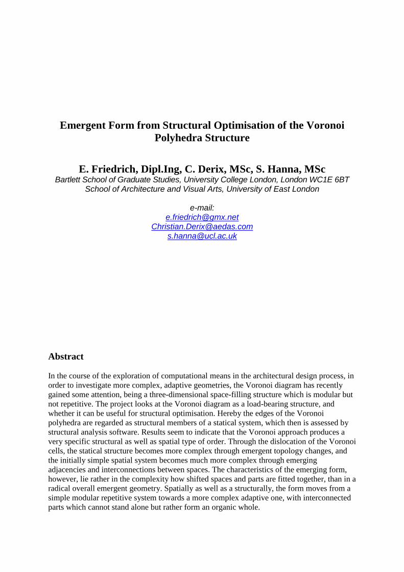
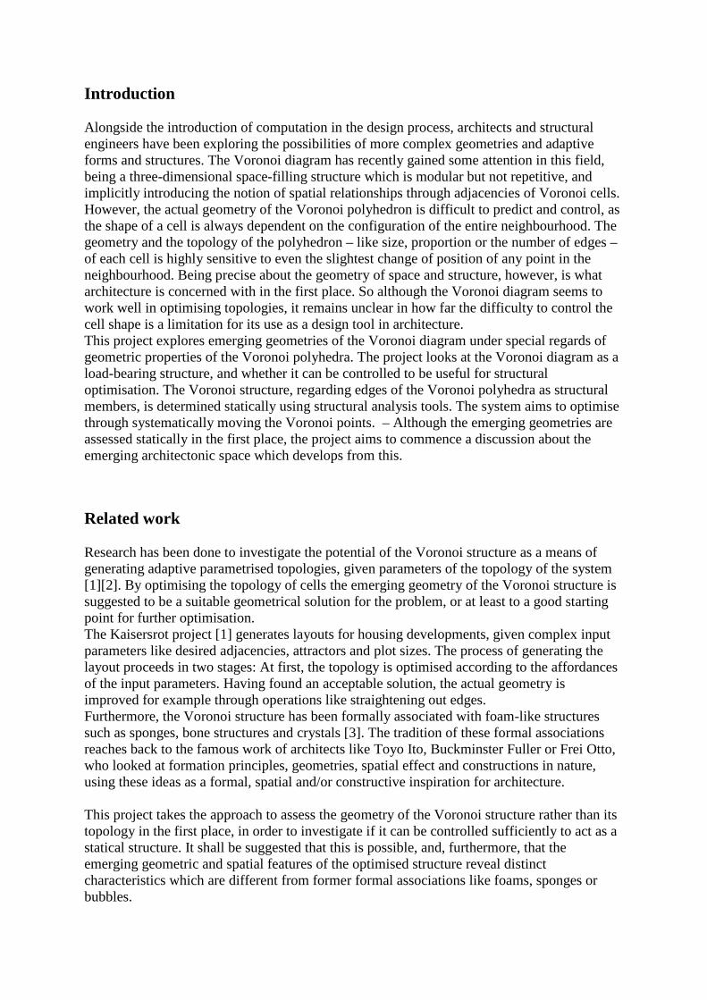
The software which was developed for this project consists essentially of two interactingcomponents: a program written in Processing [4] to generate the three-dimensional Voronoidiagram and to create a statical structure from it, and the structural analysis program OasysGSA [5] to assess the structure. GSA can be controlled remotely via a com-interface, so theprocess of analysing models and reimporting results can run automatically, triggered by theProcessing applet.The three-dimensional Voronoi structure is created from an initial configuration of points.Some of these Voronoi points are declared as 'structural points' which means that theirVoronoi cells shall be members of the structural system, and be subject to further analysis,whilst other points are just ‘surrounding cells’. The cells of the structural points are confinedby the cells of the surrounding non-structural points, and are clipped at the bottom plane.During the optimisation process, the structural Voronoi points are moved in order to seek aconfiguration which generates statically improved Voronoi polyhedra.In order to translate the Voronoi polyhedra of the structural points into a statical system, theVoronoi edges are regarded as beams, interconnected through rigid nodes. The beams areassigned some material property – a circular hollow steel profile with a diameter of 0.3 m anda wall thickness of 0.02m. Beams which connect to the bottom plane are defined as fixedsupports.Several simple load cases have been tested. The structure is always considered in terms of selfweight. Additionally, in some cases a moderate wind load has been applied which meanshorizontal force, 1 kN/m2, and suction on roof areas.Oasys GSA calculates the values of forces, moments and displacement of the structure. Theanalysis results are then reimported into the Processing applet. Now the optimisation target isto minimise the maximum displacement value of the nodes, by stepwise amending thestructure through movement of the Voronoi points.
Fig 1a Configuration of points Fig 1b Voronoi polyeder
Fig 1c Polyhedra of the structural points Fig 1: The Processing applet
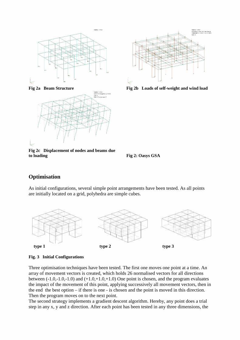
Fig 2a Beam Structure Fig 2b Loads of self-weight and wind load
Fig 2c Displacement of nodes and beams dueto loading Fig 2: Oasys GSA
Optimisation
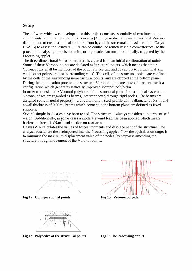
As initial configurations, several simple point arrangements have been tested. As all pointsare initially located on a grid, polyhedra are simple cubes.
type 1 type 2 type 3
Fig. 3 Initial Configurations
Three optimisation techniques have been tested. The first one moves one point at a time. Anarray of movement vectors is created, which holds 26 normalised vectors for all directionsbetween (-1.0,-1.0,-1.0) and (+1.0,+1.0,+1.0) One point is chosen, and the program evaluatesthe impact of the movement of this point, applying successively all movement vectors, then inthe end the best option – if there is one - is chosen and the point is moved in this direction.Then the program moves on to the next point.The second strategy implements a gradient descent algorithm. Hereby, any point does a trialstep in any x, y and z direction. After each point has been tested in any three dimensions, the
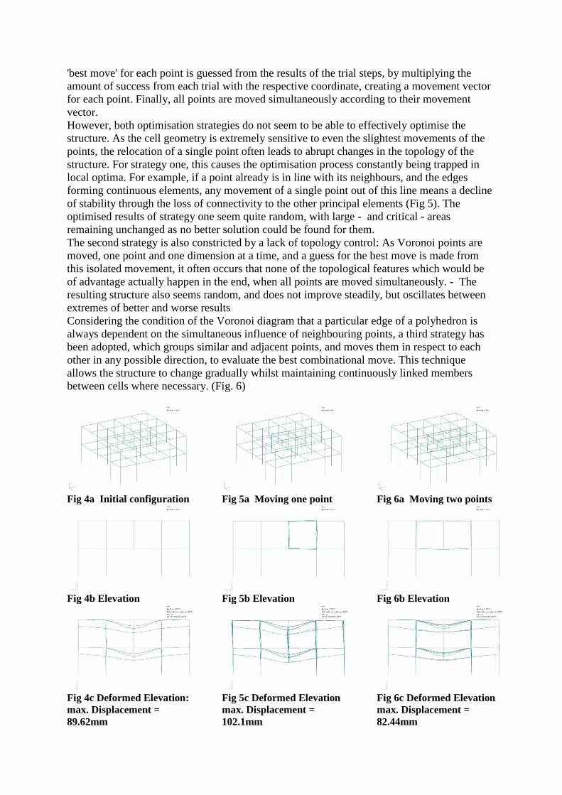
'best move' for each point is guessed from the results of the trial steps, by multiplying theamount of success from each trial with the respective coordinate, creating a movement vectorfor each point. Finally, all points are moved simultaneously according to their movementvector.However, both optimisation strategies do not seem to be able to effectively optimise thestructure. As the cell geometry is extremely sensitive to even the slightest movements of thepoints, the relocation of a single point often leads to abrupt changes in the topology of thestructure. For strategy one, this causes the optimisation process constantly being trapped inlocal optima. For example, if a point already is in line with its neighbours, and the edgesforming continuous elements, any movement of a single point out of this line means a declineof stability through the loss of connectivity to the other principal elements (Fig 5). Theoptimised results of strategy one seem quite random, with large - and critical - areasremaining unchanged as no better solution could be found for them.The second strategy is also constricted by a lack of topology control: As Voronoi points aremoved, one point and one dimension at a time, and a guess for the best move is made fromthis isolated movement, it often occurs that none of the topological features which would beof advantage actually happen in the end, when all points are moved simultaneously. - Theresulting structure also seems random, and does not improve steadily, but oscillates betweenextremes of better and worse resultsConsidering the condition of the Voronoi diagram that a particular edge of a polyhedron isalways dependent on the simultaneous influence of neighbouring points, a third strategy hasbeen adopted, which groups similar and adjacent points, and moves them in respect to eachother in any possible direction, to evaluate the best combinational move. This techniqueallows the structure to change gradually whilst maintaining continuously linked membersbetween cells where necessary. (Fig. 6)
Fig 4a Initial configuration Fig 5a Moving one point Fig 6a Moving two points
Fig 4b Elevation Fig 5b Elevation Fig 6b Elevation
Fig 4c Deformed Elevation:max. Displacement =89.62mm
Fig 5c Deformed Elevationmax. Displacement =102.1mm
Fig 6c Deformed Elevationmax. Displacement =82.44mm
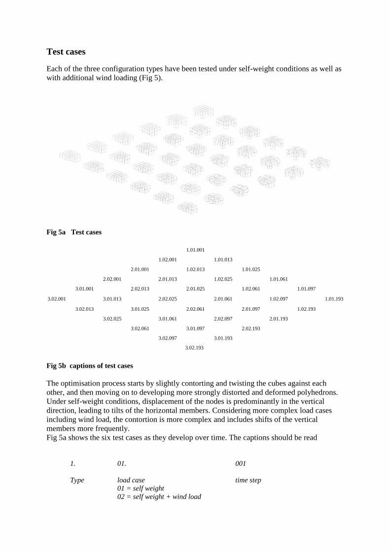
Test cases
Each of the three configuration types have been tested under self-weight conditions as well aswith additional wind loading (Fig 5).
Fig 5a Test cases
1.01.001
1.02.001 1.01.013
2.01.001 1.02.013 1.01.025
2.02.001 2.01.013 1.02.025 1.01.061
3.01.001 2.02.013 2.01.025 1.02.061 1.01.097
3.02.001 3.01.013 2.02.025 2.01.061 1.02.097 1.01.193
3.02.013 3.01.025 2.02.061 2.01.097 1.02.193
3.02.025 3.01.061 2.02.097 2.01.193
3.02.061 3.01.097 2.02.193
3.02.097 3.01.193
3.02.193
Fig 5b captions of test cases
The optimisation process starts by slightly contorting and twisting the cubes against eachother, and then moving on to developing more strongly distorted and deformed polyhedrons.Under self-weight conditions, displacement of the nodes is predominantly in the verticaldirection, leading to tilts of the horizontal members. Considering more complex load casesincluding wind load, the contortion is more complex and includes shifts of the verticalmembers more frequently.Fig 5a shows the six test cases as they develop over time. The captions should be read
1. 01. 001
Type load case time step01 = self weight02 = self weight + wind load
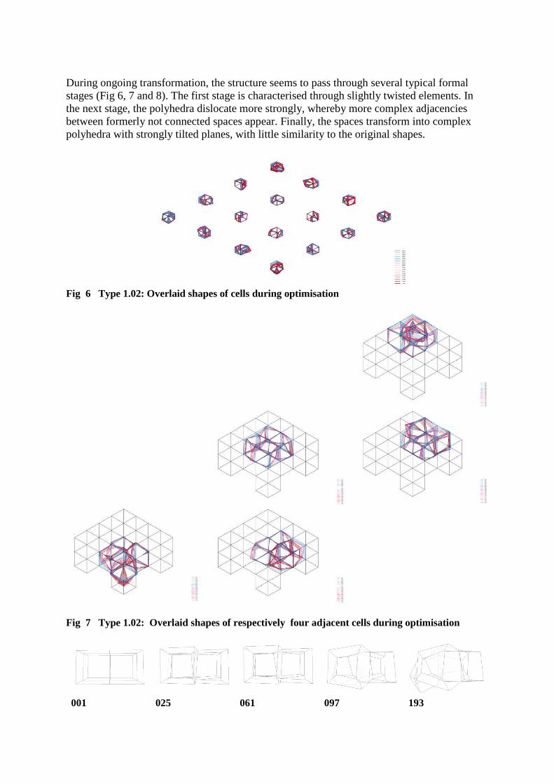
During ongoing transformation, the structure seems to pass through several typical formalstages (Fig 6, 7 and 8). The first stage is characterised through slightly twisted elements. Inthe next stage, the polyhedra dislocate more strongly, whereby more complex adjacenciesbetween formerly not connected spaces appear. Finally, the spaces transform into complexpolyhedra with strongly tilted planes, with little similarity to the original shapes.
Fig 6 Type 1.02: Overlaid shapes of cells during optimisation
Fig 7 Type 1.02: Overlaid shapes of respectively four adjacent cells during optimisation
001 025 061 097 193
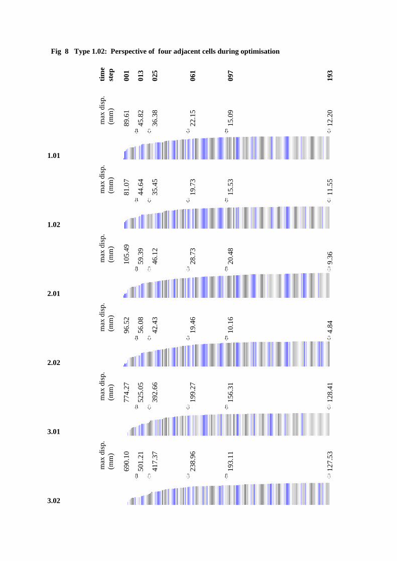
Fig 8 Type 1.02: Perspective of four adjacent cells during optimisation
tim
est
ep
00
1
01
3
02
5
06
1
09
7
19
3
max
disp
.(m
m)
89
.61
45
.82
36
.38
22
.15
15
.09
12
.20
1.01
max
disp
.(m
m)
81
.07
44
.64
35
.45
19
.73
15
.53
11
.55
1.02
max
disp
.(m
m)
10
5.4
9
59
.39
46
.12
28
.73
20
.48
9.3
6
2.01
max
disp
.(m
m)
96
.52
56
.08
42
.43
19
.46
10
.16
4.8
4
2.02
max
disp
.(m
m)
77
4.2
7
52
5.0
5
39
2.6
6
19
9.2
7
15
6.3
1
12
8.4
1
3.01
max
disp
.(m
m)
69
0.1
0
50
1.2
1
41
7.3
7
23
8.9
6
19
3.1
1
12
7.5
3
3.02
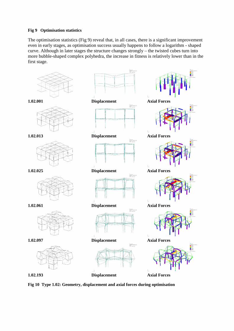
Fig 9 Optimisation statistics
The optimisation statistics (Fig 9) reveal that, in all cases, there is a significant improvementeven in early stages, as optimisation success usually happens to follow a logarithm - shapedcurve. Although in later stages the structure changes strongly – the twisted cubes turn intomore bubble-shaped complex polyhedra, the increase in fitness is relatively lower than in thefirst stage.
1.02.001 Displacement Axial Forces
1.02.013 Displacement Axial Forces
1.02.025 Displacement Axial Forces
1.02.061 Displacement Axial Forces
1.02.097 Displacement Axial Forces
1.02.193 Displacement Axial Forces
Fig 10 Type 1.02: Geometry, displacement and axial forces during optimisation
What happens in the first stage is that, although the cubes do not change radically in shapeand proportion, so does the topology of the beams (Fig 10). The beams tend to double upwhen the cells move out of the grid, and the members themselves contort against each othermaking the overall structure more stable. – The axial forces diagram reveals that, inopposition to the original structure, which is predominantly stressed by pressure forces, thedoubled edges have a pressure and a tension stressed member (colours red to yellow representtension, green to lilac indicate pressure). This effect diminishes in later stages of theoptimisation.
Conclusion
These findings seem to indicate that a considerable improvement in structural performancecan already be achieved through slight contortments and topological local changes of thestructure. The usage of the Voronoi diagram as underlying system hereby plays a crucial role,as these emergent topologies are a key property of the Voronoi diagram itself. It shall besuggested this property of the ‘instability of the topology’, which has initially be consideredas a threat, has turned out to provide rather interesting system conditions, which can beexploited for optimisation in a very distinct manner, and produces rather unique structuralsystems.
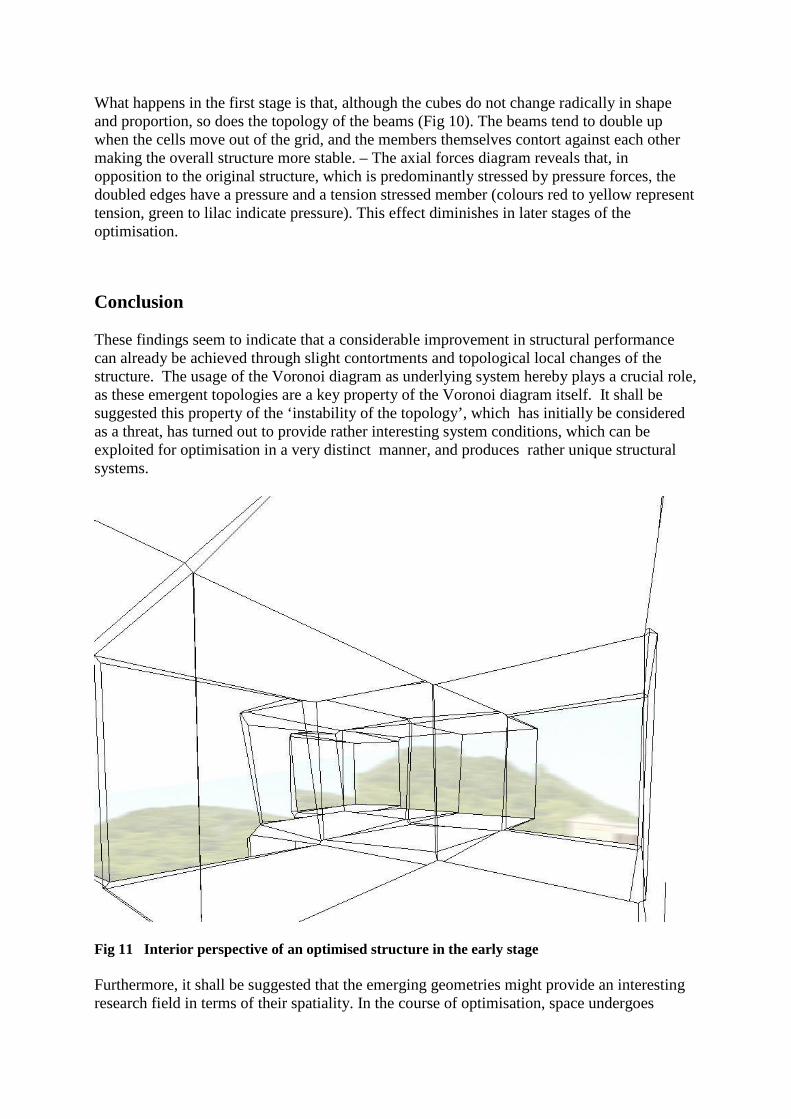
Fig 11 Interior perspective of an optimised structure in the early stage
Furthermore, it shall be suggested that the emerging geometries might provide an interestingresearch field in terms of their spatiality. In the course of optimisation, space undergoes
certain distinct 'phases': from a cube-like additive space to a stage where spaces are contorted,still ‘Cartesian’ but more interwoven, until in the end orthodox geometry gets lost and givesway to more 'organic' bubble-shaped forms. It shall be suggested that it might be the earlierstages of the process which might be of special interest, structurally as well as spatially.Here it shall be referred to some work of the Swiss Architect Valerio Olgiati, who, in his builtand theoretical work, has been deliberately developing the distortion of simple geometries asan architectural as well as a structural means.
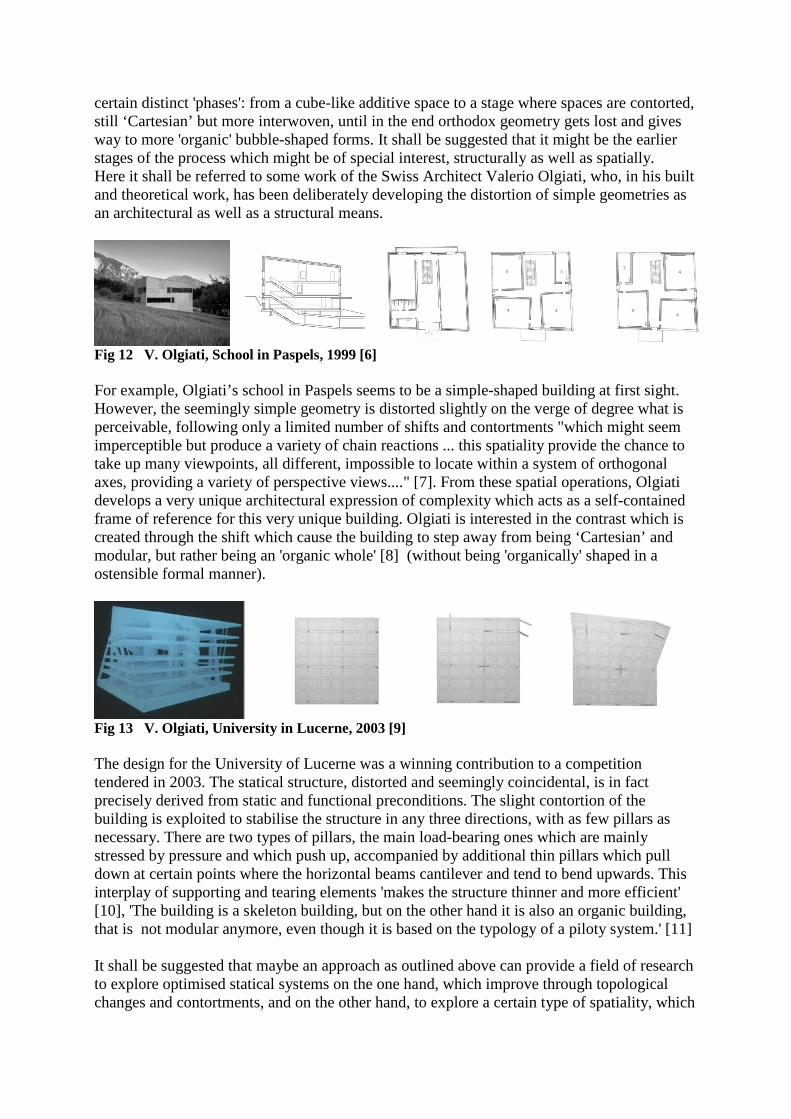
Fig 12 V. Olgiati, School in Paspels, 1999 [6]
For example, Olgiati’s school in Paspels seems to be a simple-shaped building at first sight.However, the seemingly simple geometry is distorted slightly on the verge of degree what isperceivable, following only a limited number of shifts and contortments "which might seemimperceptible but produce a variety of chain reactions ... this spatiality provide the chance totake up many viewpoints, all different, impossible to locate within a system of orthogonalaxes, providing a variety of perspective views...." [7]. From these spatial operations, Olgiatidevelops a very unique architectural expression of complexity which acts as a self-containedframe of reference for this very unique building. Olgiati is interested in the contrast which iscreated through the shift which cause the building to step away from being ‘Cartesian’ andmodular, but rather being an 'organic whole' [8] (without being 'organically' shaped in aostensible formal manner).
Fig 13 V. Olgiati, University in Lucerne, 2003 [9]
The design for the University of Lucerne was a winning contribution to a competitiontendered in 2003. The statical structure, distorted and seemingly coincidental, is in factprecisely derived from static and functional preconditions. The slight contortion of thebuilding is exploited to stabilise the structure in any three directions, with as few pillars asnecessary. There are two types of pillars, the main load-bearing ones which are mainlystressed by pressure and which push up, accompanied by additional thin pillars which pulldown at certain points where the horizontal beams cantilever and tend to bend upwards. Thisinterplay of supporting and tearing elements 'makes the structure thinner and more efficient'[10], 'The building is a skeleton building, but on the other hand it is also an organic building,that is not modular anymore, even though it is based on the typology of a piloty system.' [11]
It shall be suggested that maybe an approach as outlined above can provide a field of researchto explore optimised statical systems on the one hand, which improve through topologicalchanges and contortments, and on the other hand, to explore a certain type of spatiality, which
brings about a complex ‘organic’ adaptive space, without being ostensibly ‘organic-shaped,an adaptive spatiality different from known metaphors and analogies of ‘organic architecture’.
Credits
Many thanks to Tristan Simmonds for his introduction to Oasys GSA, his advice on theanalysis setup, and the very helpful reviews of the analysis results. Many thanks also toDaniel Glaessl for architectural and conceptual discussions!
References
[1] Kaisersrot: M.Braach in collaboration with Kees Christiaanse Architects and Planners(KCAP) www.kaisersrot.com
[2] P. Coates, C. Derix, P. Krakhofer, 2005: Generating architectural and spatialconfigurations. Two approaches using Voronoi tessellations and particle systems. GA2005
[3] m-any: T. Bonwetsch,S. Gmelin,B. Hillner,B. Mermans,J. Przerwa,A.Schlueter,R.Schmidt. www.m-any.org
[4] www.processing.org[5] www.oasys-software.com[6] Valerio Olgiati. 2G Architectural Review 2005. N.37 nexus. Images p.44 ff[7] Jaques Lucan in: Valerio Olgiati. 2G Architectural Review 2005. N.37 nexus. p.6 f[8] Valerio Olgiati, 2006: Inventioneering Architecture. Lecture accessible at:
www.architecture-radio.org/inventioneering[9] Valerio Olgiati. 2G Architectural Review 2005. N.37 nexus. Images p.99 ff[10] Valerio Olgiati, 2006: Inventioneering Architecture. Lecture accessible at:
www.architecture-radio.org/inventioneering[11] Valerio Olgiati, 2006: Inventioneering Architecture. Lecture accessible at:
www.architecture-radio.org/inventioneering