eliminating structure and intensity misalignment in … · eliminating structure and intensity...
TRANSCRIPT

Eliminating Structure and Intensity Misalignment in Image Stitching∗
Jiaya Jia§ Chi-Keung Tang†
§The Chinese University of Hong Kong†The Hong Kong University of Science and Technology
Abstract
The aim of this paper is to achieve seamless image stitch-ing for eliminating obvious visual artifact caused by severeintensity discrepancy, image distortion and structure mis-alignment, given that the input images are globally reg-istered. Our approach is based on structure deformationand propagation while maintaining the overall appearanceaffinity of the result to the input images. This new approachis proven to be effective in solving the above problems,and has found applications in mosaic deghosting, imageblending and intensity correction. Our new method con-sists of the following main processes. First, salient featuresor structures are robustly detected and aligned along theoptimal partitioning boundary between the input images.From these features, we derive sparse deformation vectorsto uniformly encode the underlying structure and intensitymisalignment. These sparse deformation cues will then bepropagated robustly and smoothly into the interior of thetarget image by solving the associated Laplace equations inthe image gradient domain. We present convincing resultsto show that our method can handle significant structureand intensity misalignment in image stitching.
1 Introduction
Image stitching generates a natural image compositegiven a set of globally registered images [19, 14] with lim-ited overlapping area. Satisfactory results on image stitch-ing requires a natural transition from one image to another,both in structure and intensity within and possibly beyondthe overlapping area. In this paper, we address the problemof image stitching in the presence of severe structure andintensity discrepancy, and propose a novel technique to si-multaneously and globally eliminate structure and intensitymisalignment among images.
Previous techniques in image stitching [14, 19] optimizefor an alignment function that minimizes the intensity dif-ference in the vicinity of the overlapping area. There is,however, no guarantee that image features or structures arealigned after intensity alignment. Recently, non-parametric
∗This research is supported by the Chinese University of Hong Kong(CUHK) Direct Grant: 2050332, and the Research Grant Council of HongKong Special Administration Region, China: AOE/E-01/99.
patch-based techniques in texture synthesis based on tex-ture deformation have been proposed in [20, 9]. To createa natural texture image of large size, the detected featuresare matched and deformed in the overlapping area betweenpatches. Therefore, local structure across patch boundariescan be maintained after the synthesis. However, these tech-niques do not have sufficient ability to handle significantcolor or intensity inconsistencies in the input images. More-over, complex global structures and detailed patterns inher-ent in many natural images may increase the ambiguity intheir 2D patch matching process, where only local featurealignment is usually performed.
Our approach is based on 1D feature matching and defor-mation propagation in natural images. Unlike the previoustechniques in image stitching (e.g., [19, 14]) or texture syn-thesis (e.g., [20, 9]), our method detects and matches thefeature points by computing a novel optimal partitioningbetween the overlapping images. Feature matching alongthe optimal partition boundary is performed. We uniformlyrepresent the global structure alignment by the feature de-formation vectors, which are propagated robustly from theoptimal partition toward the interior of the images. Ourpropagation is performed in the gradient domain, thus theintensity discrepancy among images can be effectively re-duced during the deformation propagation.
The rest of our paper is organized as follows. Section 2reviews related work. Then, in section 3, we present ouroptimization algorithm in detail. Main results in this pa-per and comparison with previous methods are presented insection 4. We conclude our paper in section 5.
2 Related work
Our image stitching aligns not only image intensity butalso image structure. In this section, we review related workin maintaining smooth image transition and deriving struc-ture deformation for image alignment.
2.1 Image stitching
Many image registration methods have been developedin recent years. When the input images have significant in-tensity difference, color blending with the use of a weight-ing mask over the overlapping area is commonly adoptedfor generating a smooth intensity transition. For instance,
1

the video mosaic proposed in [17] uses the Levenberg-Marquardt method to estimate the homography matrix foraligning two overlapping images. To reduce visible arti-facts and local misalignment, the method blends the over-lapping area by a bilinear weighting function. In [19], thefeather-based algorithm was applied which uses averagingand interpolation functions to reduce intensity difference.Unnatural seam, however, is still inevitable since only lo-cal operations are performed in these methods. Burt et al.[4] used a multi-resolution spline to perform blending. Notethat all these methods only locally blend images in the over-lapping area to transit the images taken from one lightingenvironment to another.
The local alignment method proposed in [18] for per-forming deghosting works well in many situations. How-ever, it requires the recovery of the true 3D ray directions,which makes it difficult to handle occlusion errors and re-stricts it to only real images. The color or intensity differ-ence among images may also make the method trap intolocal minimum.
Methods using optimal seam were recently proposed tocomposite image or textures [8, 12, 1]. These methodsfirst compute the color difference in the overlapping areabetween the two input textures or images. Then dynamicprogramming [8] or graph cut [12] is used to compute anoptimal partition that produces the least color difference be-tween the two textures/images. In [7], the partitions amongdifferent motions were also computed. However, whenthere exists large color difference in the overlapping area,satisfactory results cannot be produced.
The two methods described in [10, 11] combine imageregistration and intensity correction into a single optimiza-tion framework. The method in [10] requires the inter-nal camera parameters be known before the optimization,whereas the tensor voting method described in [11] com-putes intensity alignment and corrects color globally at allthe image pixels without any prior knowledge on the cam-era. However, structure misalignment may be resulted sincestructure was not explicitly considered in these methods.
Levin et al [14] proposed an image stitching algorithmthat operates in the gradient domain, and introduced anoptimization method based on the gradient strength in theoverlapping area. This method produces good results in thepresence of local or global intensity difference between thetwo input images. However, large structure misalignmentcannot be handled by this method.
2.2 Structure deformation
Structure deformation and alignment have been topicsof interest in medical image registration, especially in non-rigid transform for registering medical images of differentmodalities. Bajcsy et al. [2] first proposed to use the forcesof external stretching and internal smoothness to register
medical images. A multiscale technique using a pyrami-dal representation is often applied. In [6], a two-step ap-proach was proposed for the nonlinear registration of brainimages. In the first step, an one-to-one mapping betweencorresponding boundaries are established. The second stepdeforms these boundaries subject to certain criteria. Thismethod requires the corresponding boundaries be homo-thetical to each other, that is, they are related by a uniformscaling and an arbitrary length-preserving bending. Elasticregistration [2] cannot precisely handle detailed and localfeatures, which are common in natural images.
Fluid registration [3, 13] uses the non-rigid methodcalled viscous fluid registration to align medical images.Unlike the elastic models where the desirable deformationmay not be obtained because of the internal strain in theelastic continuum, these methods can achieve the desirabledeformation since internal forces will disappear over time.However, they may easily introduce blurring and producenon-negligible distortion.
Recently, feature matching methods in texture synthe-sis were proposed in [20, 9]. In [20], the binary featuremaps were first produced by using a two-pass Canny edgefilter. Then a 2D feature matching process is applied. Thismethod detects features in the overlapping area in multi-ple scales. However, their binary feature representation isunsuitable for feature matching in the presence of variousfeature types, which is common in natural images. Thesecomplications may lead to an incorrect warping function.Moreover, since [20] is designed for texture synthesis, it hasinsufficient ability to correct intensity misalignment. Ourmethod, on the contrary, matches salient features on thepartition boundary and avoid considering complex featurejunctions. In [9], a deformation function was introducedto simultaneously maximize the color matches while mini-mizing the deformation distortion over the overlapping area.However, only local minima can be achieved, and the resultmay be easily affected by the intensity inconsistency be-tween images. Our method addresses the intensity inconsis-tency by considering structure deformation in the gradientdomain, and by smoothly propagating a set of sparse defor-mation vectors to the interior of images. Hence, our methodachieves precise alignment and is free from the problem ofbreaking continuous structures.
3 Our method
For clarity, in this paper, we consider the fundamentalcase of stitching two images IS and IT , where the overlap-ping area is Ω. Our technique can be readily generalizedif more images are present. Also, we describe one case ofstructure deformation that deforms (a region of) IT to matchwith IS because the other cases are similar. Below, ∇ repre-sents the gradient operator [ ∂
∂x ,∂∂y ], where ∇i, i ∈ x,y, is
the respective principal gradient components.

(a) (b) (c) (d) (e)
(f) (g) (h) (i) (j)
Figure 1: Structure deformation. (a) and (b) are two input images. The overlapping area is indicated by the dash lines. (c) Our methodfirst computes an optimal partition in the gradient domain. (d) The y-component of the gradient map in the gray scale channel after derivingthe optimal partition. (e) The features are matched along the optimal partition, and are further propagated inside the image. We show they-component of the gradient map in the gray scale channel after propagation. (f) Result from feathering. (g) Result obtained using theoptimal seam in the gradient domain. (h) Result by the GIST1 method proposed in [14], where artifact is also observed because featuresare not aligned in the method. (i) Result obtained using the method in [20]. Note that this method is designed for texture synthesis. Thewarping method cannot produce smooth transition in the presence of significant intensity difference. (j) Our final result. Note that not onlyfeatures are properly aligned but also colors are globally propagated in the image as well.
Our general image stitching does not have any restrictionon the shape of the underlying structures to be aligned. Theoverview of our method is as follows, where each step willbe described in detail in this section.
1. Compute an optimal partition between the aligned im-ages. This step generates a stitching boundary betweenthe overlapping images that minimizes the cost func-tion to be defined.
2. Detect and match features along the stitching boundarygenerated in the previous step.
3. The matched features are associated with their corre-sponding deformation vectors. They are propagatedfrom the partition boundary to the interior of the im-ages to maintain smooth transition in structure and in-tensity.
4. Construct a deformed gradient image based on the de-formation vector computed at each pixel and recon-struct the final output image by solving the Poissonequations on the deformed gradient image.
Fig. 1 shows a simple example where the two shapesin (a) and (b) are to be stitched. The result from step 1is shown in (c) where an optimal partitioning boundary isgenerated. (d) shows the y-component of the correspondinggradient map in the gray scale channel. Along the partitionboundary, the features, namely, the edges, are matched au-tomatically. The deformation corresponding to the matchedfeatures is smoothly propagated across the entire image.Fig. 1(e) shows the y-component of the resulting gradientmap in the gray scale channel. Our final result is shown in(j), which clearly shows that the features are smoothly con-nected and the color difference between the two images isglobally minimized. Here, we also compare our approach
IS IT Is It∂ I′t ∂ It −∂ I′t
Ωt
Ωt
Ωs
Ωs
Figure 2: Optimal partition. Left: images IS and IT are overlap-ping in Ω. The partition divides Ω into Ωs and Ωt . Right: the newpartitioned images are Is and It . We define the intersection Is ∩ Itas the optimal partition boundary ∂ I′t , which is indicated by theorange partition boundary. The blue boundary of It is ∂ It −∂ I′t .
with other techniques. (f) is the feathering result. (g) isthe stitching result generated from the optimal seam in thegradient domain. Without explicit feature alignment, vi-sual artifacts resulting from edge discontinuity and colorinconsistency are observed. (h) is the result generated fromGIST1 [14] which also operates in the image gradient do-main. Structure misalignment can also be observed sincestructure alignment is not considered. (i) is the result pro-duced by the texture deformation method [20] which cannotglobally eliminate color inconsistency.
3.1 Optimal partition
In the first step, we compute an optimal partition in theoverlapping area Ω to minimize the structure misalignment.Here, we formulate the partitioning problem as one of la-beling, and adopt the graph cuts method to find an optimalsolution. We define the gradient alignment cost S(p,q) be-tween any adjacent pixels p and q to be the sum of the com-

puted values in the rgb color channels:
S(p,q) = ∑r,g,b
((1−β )Sm +βSd), (1)
where Sm and Sd are two costs measuring the gradientsmoothness and similarity between the neighboring pixels,which will be defined shortly. β is a weight used to balancethe relative influence of the two costs, which is set to be0.3 in our experiments. Before the above computation, wesmooth both images by using a Gaussian filter with a diam-eter of 5. Denoting the smoothed output image as I∗. Sm isdefined as follows:
Sm(p,q) = ||∇I∗S (p)||+ ||∇I∗S (q)||+ ||∇I∗T (p)||+ ||∇I∗T (q)||, (2)
where ||∇ · || represents the norm of the gradient for eachpixel. Thus Sm takes the gradient smoothness into account,which effectively avoids the partition from breaking objectedges in both input images. Sd is defined as:
Sd(p,q) = ||∇xI∗S (p)−∇xI∗T (p)||+ ||∇xI∗S (q)−∇xI∗T (q)||+||∇yI∗S (p)−∇yI∗T (p)||+ ||∇yI∗S (q)−∇yI∗T (q)|| (3)
where each term above represents the gradient-level simi-larity at the same pixel location in the overlapping area. Sd
thus penalizes pixel dissimilarity in the gradient domain. Asa result, Sd favors the partitioning curve to pass through thepixel locations where the neighboring pixels have similargradient in the overlapping area.
Therefore, S(p,q), combining Sm and Sd , enables thegraph cuts method to produce a good initial partition withthe maximum continuity in the gradient domain. Fig. 2 il-lustrates that the partition divides Ω into Ωs and Ωt , whichgenerates two new regions Is and It (colored in gray andgreen respectively). The intersection Is ∩ It is the optimalpartition ∂ I′t . The set of boundary pixels of It excluding ∂ I′tare denoted by ∂ It − ∂ I′t . ∂ I′t and ∂ It − ∂ I′t are indicatedas orange and blue curves respectively on the right side ofFig. 2.
Comparing to the optimal seam methods proposed in [8,12], our new cost function takes into account both the gra-dient smoothness and gradient similarity. Therefore, eventhe two input images have significant difference in inten-sity, our method can still optimize the gradient continuity.Moreover, our partition favors smooth area in both images,which effectively reduces the feature complexity along ∂ I′t ,which will in turn reduce the matching ambiguity in the fol-lowing steps. The comparisons of the partitioning resultsbetween the previous optimal seam methods and ours willbe shown in section 4.
3.2 Feature detection
The optimal partition obtained above is subject to thecontinuity constraint given by S(·). However, structure dis-continuity may still be inevitable in some cases, such as the
∂ I′t
∂ I′t
Is It
(Vx,Vy)
Figure 3: After optimal partitioning, there may still exist struc-ture misalignment. Along the partition boundary, similar features(black and blue dots) in the two images should be matched. Hence,in the zoom-in view, features in It should be deformed in the di-rection (Vx,Vy) as indicated by the dashed arrow.
one illustrated in Fig 1(c). In this section, we propose amethod based on feature matching to correct the misalign-ment along the optimal partition boundary.
Our observation is that in most situations if the structureis not aligned during the optimal partitioning, the featuresmay have been broken at different locations along their re-spective stitching boundaries. Accordingly, a deformationvector can be defined, as shown in Fig. 3. For clarity of de-piction, in the following, we describe our structure deforma-tion method by matching features from It to Is. Hence, onlythe partition boundary ∂ I′t will be considered. The analo-gous problems that Is is deformed to match It , or both Is
and It are deformed to match their mean respective featurepoints, are similar.Feature localization The human eye is more sensitive toedge discontinuity than to smooth color transition. Thus, inimage stitching, structure misalignment present in a road,building, or the horizon will look more obvious to us thanthe intensity misalignment present in a large grassland, forinstance.
Accordingly, we apply a Gaussian smoothing process,together with the anisotropic filter proposed in [16], on Is
and It along ∂ I′t respectively. We use two rotated kernelsFe
θ and Foθ defined in [16] to construct the square modulus
W (x,y,θ) = (Feθ ∗ I)2 +(Fo
θ ∗ I)2. The angle with the maxi-mum W indicates the edge orientation at pixel (x,y). Com-paring with Canny edge detection [5], this method is morerobust and precise for feature localization and detection, es-pecially when junctions are present. In our experiments, wefound that a sparse sampling of θ in 10-degree increment issufficient in all cases.Feature representation We denote all features detectedin image Is and It along ∂ I′t (orange curve on the right ofFig. 2) as f 1
s , f 2s , · · · , f m
s and f 1t , f 2
t , · · · , f nt respectively,
where m and n are the total number of features along ∂ I′t inIs and It . Note that the features are ordered along ∂ I′t , andeach feature point f k
s (or f kt ) is associated with a feature
direction θs(k) (or θt(k)) and the computed energy Ws(k)

∂ I′t
∂ I′t
f 1s
f 1t
d( f 1s , f 1
t )
Figure 4: The partition boundary ∂ I′t (left) can be straightenedinto a line segment (right) by considering the relative distance ofthe sparse features along ∂ I′t . The path distance d(·) between twofeatures in Is and It is measured by their distance in the line seg-ment.
(or Wt(k)).The reason that only features at the boundary pixels are
computed is that without taking into account all pixels inthe overlapping area, it is unnecessary to consider complexstructures such as T-junctions and W-junctions. The optimalpartitioning introduced in the previous section effectivelyreduces the number of feature points by using a smoothnessconstraint.
3.3 Feature matching
We construct a boundary line segment as shown in Fig.4. All pixels along ∂ I′t will be placed in it with a sequenceaccording to their respective distances to the starting pixelof ∂ I′t , shown as the orange arrow in Fig. 4. We defined( f k1
t , f k2s ) between any two features f k1
t and f k2s as the dis-
tance along the 1D line. One example is shown on the rightof Fig. 4.
We measure the similarity of two features f k1t and f k2
s inIs and It by considering the computed energy, feature anglesand their path distances d(·):
e( f k1t , f k2
s ) = α(Wt(k1)−Ws(k2))2 +
γ(θt(k1)−θs(k2))2 +(1−α − γ)d( f k1t , f k2
s )2, (4)
where (Wt(k1)−Ws(k2))2 measures the energy distance be-tween the two features, so a strong edge will not be matchedwith a relatively smooth region. (θt(k1)− θs(k2))2 con-strains that the matched features should not differ too muchin their directions. d(·), on the other hand, constrains thatthe two features to be matched should not be too far awayfrom each other. The three terms above are normalized be-fore the actual calculation. We set α and γ as 0.4 and 0.2 inour experiments.
Given the feature measurement e( f k1t , f k2
s ) between eachfeature pair in Is and It , we enqueue all the feature pointsin It and apply the following algorithm to construct featurematches, by considering the case that It is deformed to alignwith Is :
1. Select the feature f k1t in the remaining queue with the
largest energy Wt(k1), which represents the strongestfeature point.
2. We search for a feature point f k2s with the smallest sim-
ilarity cost e( f k1t , f k2
s ). If the match does not violatethe containment rule (below), these two points will bematched and f k1
t will be removed from the queue.
We define the containment rule as follows:
Suppose k′1 ≤ k1, f k1t is matched to f k2
s and fk′1t is
matched to fk′2s . Then we must have k′2 ≥ k2, and vise
versa. This constrains that no edge intersection will beproduced by structure deformation to prevent unneces-sary structure distortion.
3. If the queue is not empty, goto step 1 and continue thealgorithm.
This algorithm agrees with our human perception thatstrong structures should be aligned properly and not be frag-mented, as indicated by the fact that the strongest featurepoints are always picked first.
For each feature matching pair ( f k1t , f k2
s ),we construct a deformation vector V( f k1
t ) =Vx( f k1
t ),Vy( f k1t ),V∇x( f k1
t ),V∇y( f k1t ). Vx and Vy are
the x and y components of the vector pointing from f k1t to
f k2s in the image space, as shown on the right of Fig. 3.
V∇x and V∇y measure the difference in the gradient map
between ( f k1t and f k2
s ), and is calculated as:
V∇i( f k1t ) = ∇iIt( f k1
t )−∇iIs( f k2s ), i ∈ x,y. (5)
Therefore, our structure deformation not only considersthe geometric difference in the image plane, but also thegradient difference in feature alignment.
3.4 Deformation propagation
For clarity, similar to section 3.2, we only describe thedeformation from It to Is. The generalization to handle othercases is similar. To smoothly propagate deformation fromthe sparse features along ∂ I′t into image It , we define the de-formation area St to indicate the area that should be affectedby the propagated deformation. By default, we allow thedeformation to propagate into the entire image It , namely,St = It . However, it is often adequate to apply local struc-ture deformation in the overlapping area, so another goodchoice is St = Ωt . In fact, St can be arbitrarily defined bythe user to derive various image stitching effects.
In our boundary configuration shown in Fig. 5, the yel-low region is St , within which deformation is performed.The blue ribbon is the boundary of St , that is, ∂St . Thegreen region represents It −St . Since it is outside of St , thisregion should not be affected by any deformation.

1
2
∂ I′t
St It −St
Figure 5: Boundary condition. In It , if a pixel pi is not lying on∂ I′t , and one of its neighborhood pixel is in It −St , we set the valueas 0, as shown in block 2. Otherwise, if the pixel is not a featurepoint, its value is undetermined, as shown in block 1.
We consider the deformation vector assignment for apixel pi ∈ ∂St under the following three conditions. 1) pi
is a feature point. The corresponding deformation vector isalready computed in the previous section. 2) pi is adjacentto the pixels in It −St , e.g., the red pixel in box 2 in Fig. 5.To avoid producing structure discontinuity between St andIt −St , the deformation of these pixels should be zero so thatSt and It −St can be aligned structurally. 3) pi is not a fea-ture point, and also not adjacent to It −St . In this case, pi’sdeformation is undetermined, as the red pixel of block 1 inFig. 5. Accordingly, we define the transformation vector asfollows:
V(pi) =
V( f kt ) pi = f k
t0 ∃p j, p j ∈ Npi &p j ∈ It −St
(6)
where Npi is the 4-connected neighborhood of pi and 0 =0,0,0,0. For all other boundary pixels not defined inEqn. 6, we use the Neumann boundary condition to mea-sure their deformation, that is, ∇V(pi) = 0.
Therefore, to smoothly propagate the deformation insideimage It , we propose to solve the minimization equation:
V∗ = argminV
∫ ∫p∈St
||∇V||2d p (7)
which is equivalent to solving the Laplace’s equation:
∆V = 0 with V|∂St = V∗|∂St (8)
where ∆ is the Laplacian operator. We solve the equationby using the Gauss-Seidel iterative method with a multi-grid under the boundary conditions, for each componentin V respectively. After the minimization, each pixel in St
is associated with a deformation vector. Finally, using thedeformation vectors at all the pixels in St , we perform aninverse mapping with bilinear interpolation in the gradientdomain in St to construct the deformed gradient map (Fig.1(e)). The final image is obtained by solving the Poissonequations on the deformed gradient map.
4 Results
We demonstrate our method using three difficult exam-ples. Comparison with other methods using our implemen-tation are also given.
(a) (b)
(c)
(d) (e) (f)
Figure 6: Lamp post. (a) and (b) are the two registered images.(c) is our image stitching result where the lamp post is seamlesslyaligned. (d) and(e) are zoom-in views of the results generated by:(d) the optimal seam method and (e) feathering. (f) Our resultwith St = It , where structures are globally aligned with minimumdistortion.
Fig. 6 shows one example where the two input images in(a) and (b) have large discrepancy both in color and struc-tures. (c) shows our generated result. (d) is the result gen-erated by the optimal seam method. (e) is the feathering re-sult. (i) shows our result. Our method can handle color andstructure deformation within the same framework, whichcan successfully solve the deformation problem for struc-ture and intensity alignment between the two images.
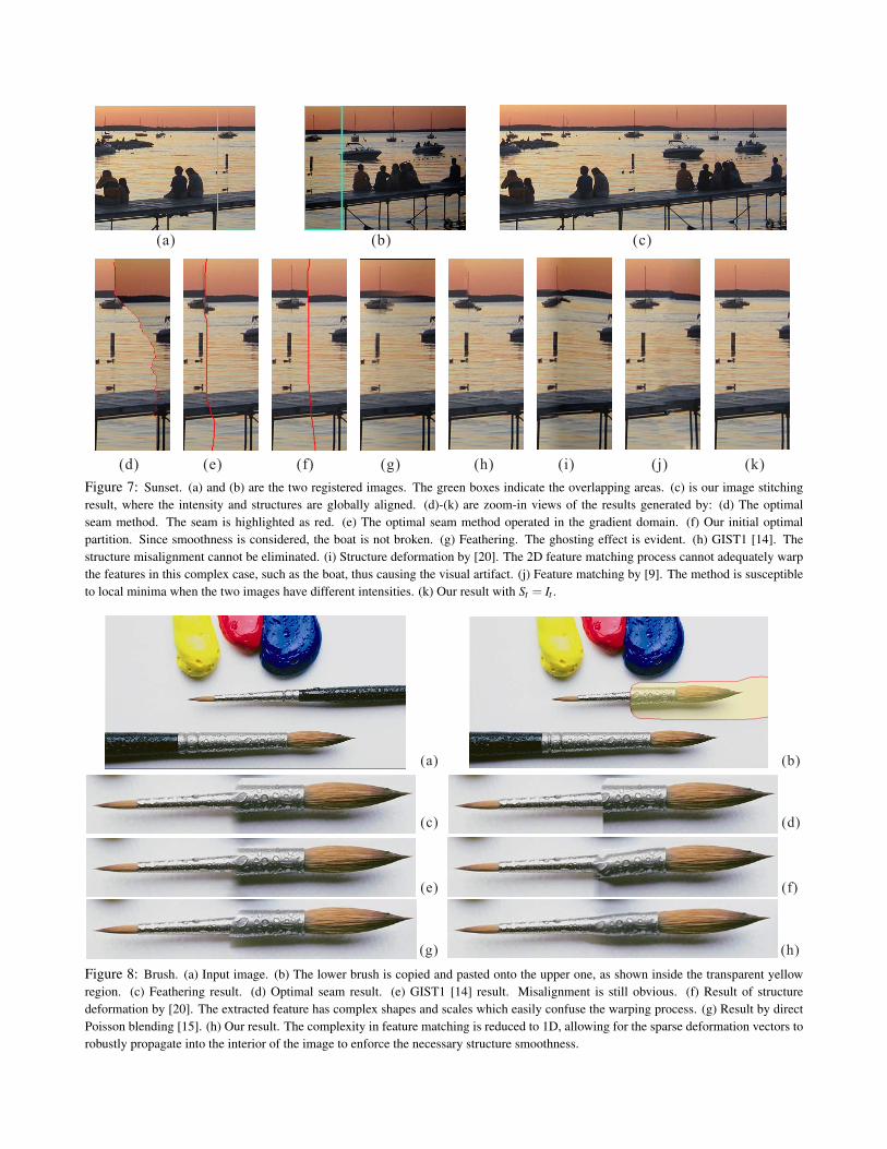
In Fig. 7 (a) and (b), we show two images taken froma sunset scene. The alignment process is difficult becauseof the local displacement and the small overlapping areas,shown in the green boxes in the figure. Our result is shownin (c). Note that the structures are globally aligned and theintensities are also matched. From (d) to (k), we comparethe results generated using previous methods. (d) is the re-sult generated by the optimal seam method [8]. Since nopixels are similar in intensity, the result produces an obvi-ous seam (indicated by the thin red curve). (e) is the resultobtained by the optimal seam method operated in the gra-dient domain. Color difference is alleviated in the stitchedresult. Our method also performs optimal partitioning asdescribed in section 3.1. Taking structure smoothness intoconsideration which makes the matching process more ro-bust, our method will not destroy the boat as shown in (f).has also been significantly reduced. (g) is the feathering re-sult where the ghosting effect is obvious. (h) shows the re-
(a) (b) (c)
(d) (j)(e) (f) (g) (h) (i) (k)
Figure 7: Sunset. (a) and (b) are the two registered images. The green boxes indicate the overlapping areas. (c) is our image stitchingresult, where the intensity and structures are globally aligned. (d)-(k) are zoom-in views of the results generated by: (d) The optimalseam method. The seam is highlighted as red. (e) The optimal seam method operated in the gradient domain. (f) Our initial optimalpartition. Since smoothness is considered, the boat is not broken. (g) Feathering. The ghosting effect is evident. (h) GIST1 [14]. Thestructure misalignment cannot be eliminated. (i) Structure deformation by [20]. The 2D feature matching process cannot adequately warpthe features in this complex case, such as the boat, thus causing the visual artifact. (j) Feature matching by [9]. The method is susceptibleto local minima when the two images have different intensities. (k) Our result with St = It .
(a)
(c)
(e)
(g)
(b)
(d)
(f)
(h)
Figure 8: Brush. (a) Input image. (b) The lower brush is copied and pasted onto the upper one, as shown inside the transparent yellowregion. (c) Feathering result. (d) Optimal seam result. (e) GIST1 [14] result. Misalignment is still obvious. (f) Result of structuredeformation by [20]. The extracted feature has complex shapes and scales which easily confuse the warping process. (g) Result by directPoisson blending [15]. (h) Our result. The complexity in feature matching is reduced to 1D, allowing for the sparse deformation vectors torobustly propagate into the interior of the image to enforce the necessary structure smoothness.

sult by GIST1 [14], where the imposed smoothness cannoteliminate the misalignment in structure. (i) is the structuredeformation result obtained by [20]. 2D matching of theextracted features cannot adequately handle complex struc-tures, such as the boat, and causes the incorrect warping re-sult. The local distortion is also inevitable. (j) is the featurematching result by [9]. The significant difference in globalimage intensity makes their optimization method suscepti-ble to local minima and thus causes inaccurate alignment.Starting from the optimal partition, our result shown in (k) isobtained by our local feature matching, which does not needto consider any complex shapes in the 2D space. Moreover,the necessary structure deformation is propagated properlyand smoothly toward the interior of the images, which guar-antees that no visual features will be broken while structurealignment is enforced during the propagation. In this exam-ple, we set St = It to globally reduce the distortion effort inthe deformation process.
Our method can be readily applied to unconventional im-age stitching with arbitrary overlapping areas. In Fig. 8(a),we only use a single input image, where the lower brushis copied to align with the upper one. The user draws themask as shown in the yellow region in (b). The featheringresult is shown in (c), where misalignment is obvious. (d)shows the result obtained by the optimal seam method. Thecorresponding pixels along the boundary are mostly differ-ent in terms of intensity, thus resulting in the obvious seamas shown. (e) shows the result by the GIST1 method [14],which cannot eliminate misalignment in this example. (f)shows the result obtained using the deformation method in[20]. Since this example has complex features at multiplescales and in various scales, their warping function mixes upthe interweaved features and causes significant alignmenterror. Shown in (g) is the result produced by direct Poissonblending [15]. Our result is shown in (h), where structuresand intensities are aligned along the stitching boundary, andare smoothly propagated into the interior of the pasted re-gion.
5 Conclusion
In this paper, we propose a novel approach of image de-formation for image stitching where the overlapping regionsmay contain significant intensity inconsistency and struc-ture misalignment. Instead of searching all possible pairs offeatures in the given images to derive the optimal pair foralignment, we propose to detect only the necessary featuresalong the partitioning boundaries, and use them to con-struct the deformation vectors. By doing so, we can avoidthe complex problem arisen in multiscale feature detectionand matching, especially when the input images have dif-ferent levels of details. From the sparse features detectedalong the partitioning boundary, we propagate the deforma-tion into the target image smoothly and robustly by solv-
ing the associated Laplace equation. Structure deformationand color correction are simultaneously achieved within thesame framework operating in the image gradient domain.Hence, our method can uniformly handle difficult sceneswith severe structure and intensity misalignment among im-ages, as shown in the result section.
References[1] Aseem Agarwala, Mira Dontcheva, Maneesh Agrawala, Steven
Drucker, Alex Colburn, Brian Curless, David Salesin, and MichaelCohen. Interactive digital photomontage. In Proc. of SIGGRAPH2004, 2004.
[2] R. Bajcsy and S. Kovacic. Multiresolution elastic matching. Com-puter Vision, Graphics and Image Processing, (46):1–21, 1989.
[3] Morten Bro-Nielsen and Claus Gramkow. Fast fluid registration ofmedical images. Proceedings of Visualization in Biomedical Com-puting, (1131):267–276, 1996.
[4] P. J. Burt and E. H. Adelson. A multiresolution spline with appli-cations to image mosaics. In ACM Transaction on Graphics, pages2(4), 217–236, October 1983.
[5] J. Canny. A computational approach to edge detection. IEEE Trans-action on Pattern Analysis and Machine Intelligence, 8(6):679–698,1986.
[6] C. Davatzikos, J.L. Prince, and R.N. Bryan. Image registration basedon boundary mapping. IEEE Transactions on Medical Imaging,(15):112–115, 1996.
[7] James Davis. Mosaics of scenes with moving objects. In CVPR 1998,1998.
[8] Alexei A. Efros and William T. Freeman. Image quilting for texturesynthesis and transfer. Proceedings of SIGGRAPH 2001, pages 341–346, August 2001.
[9] Hui Fang and John C. Hart. Textureshop: Texture synthesis as aphotograph editing tool. Proceedings of SIGGRAPH 2004, 2004.
[10] D. Hasler and S. Susstrunk. Colour handling in panoramic photogra-phy. In Proc. of SPIE, Jan 2001.
[11] J. Jia and C.-K. Tang. Image registration with global and local lumi-nance alignment. In ICCV03, pages I: 156–163, 2003.
[12] Vivek Kwatra, Arno Schodl, Irfan Essa, Greg Turk, and Aaron Bo-bick. Graphcut textures: Image and video synthesis using graph cuts.ACM Transactions on Graphics, SIGGRAPH 2003, 22(3):277–286,July 2003.
[13] H. Lester and S.R. Arridge. Summarising fluid registration by thin-plate spline warps with many landmarks. Proceedings of MedicalImage Understanding and Analysis, 1997.
[14] Anat Levin, Assaf Zomet, Shmuel Peleg, and Yair Weiss. Seamlessimage stitching in the gradient domain. In ECCV04, May 2004.
[15] Patrick Perez, Michel Gangnet, and Andrew Blake. Poisson im-age editing. ACM Transactions on Graphics (SIGGRAPH’03),22(3):313-318, 2003.
[16] P. Perona and J. Malik. Detecting and localizing edges composed ofsteps, peaks and roofs. Proceedings of ICCV 1990, 1990.
[17] R. Szeliski. Video mosaics for virtual environments. In IEEE Com-puter Graphics and Applications, pages 22–30, March 1996.
[18] Richard Szeliski and Heung-Yeung Shum. Construction ofpanoramic image mosaics with global and local alignment. Inter-national Journal of Computer Vision, 36(2):101–130, 2000.
[19] M. Uyttendaele, A. Eden, and R. Szeliski. Eliminating ghosting andexposure artifacts in image mosaics. In CVPR 2001, 2001.
[20] Qing Wu and Yizhou Yu. Feature matching and deformation fortexture synthesis. Proceedings of SIGGRAPH 2004, 23(3):362–365,2004.