elg4125: flexible ac transmission systems (facts)rhabash/elg4125facts.pdf · elg4125: flexible ac...
TRANSCRIPT
ELG4125: Flexible AC Transmission Systems (FACTS)
The philosophy of FACTS is to use power electronics for
controlling power flow in a transmission network, thus allowing the
transmission line to be loaded to its full capability.
Power electronics controlled devices, such as static volt-ampere
reactive (VAR) compensators have been used in transmission
networks for many years.
Flexible AC Transmission System (FACTS) is an integrated
concept based on power electronic switching converters
and dynamic controllers to enhance the system utilization
and power transfer capacity as well as the stability, security,
reliability and power quality of AC system interconnections.
FACTS is a collection of thyristor-based controllers,
including phase shifters, advanced static VAR
compensator, dynamic brake, modulator series capacitor,
load tap changer, fault current limiter, and perhaps other
that have yet to be invented.
In recent years, energy, environment, right-of-way, and
cost problems delayed the construction of both generation
facilities and new transmission lines. This has necessitated
a change in the traditional power system concepts and
practices; better utilization of existing power systems has
become imperative.
Objectives of FACTS
• Control power so that it flows on the desired routes. Power
may be controlled by applying a voltage in the midpoint or by applying a voltage in series with the line and in phase quadrature with the current flow or by regulating the
magnitude of sending and receiving end voltages (This is more effective than the previous techniques)
• Increase loading capacity of transmission lines.
• Prevent blackouts.
• Improve generation productivity.
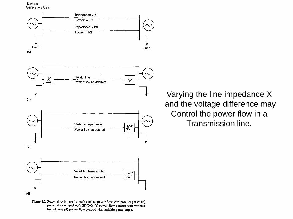
Varying the line impedance X
and the voltage difference may
Control the power flow in a
Transmission line.
What Limits the Loading Capability?
Thermal
For overhead line, thermal capability is a function of ambient temperature, wind conditions, conditions of conductor, and ground clearance. The FACTS
technology can help in making an effective used of newfound line capability.
Dielectric Being designed very conservatively, most lines can increase operation voltage by 10% or even higher. FACTS technology could be used to ensure acceptable
over-voltage and power flow conditions.
Stability The stability issues that limit the transmission capability include:
transient stability, dynamic stability, steady-state stability, frequency collapse. Voltage collapse, and sub-synchronous resonance.
The FACTS technology can certainly be used to overcome any of the stability limits.
Power Factor Correction
Most loads on an electrical distribution system fall into one of three categories; resistive, inductive or capacitive. In most plant, the most common is likely to be inductive. Typical
examples of this include transformers, fluorescent lighting and AC induction motors. Most inductive loads use a conductive
coil winding to produce an electromagnetic field, allowing the motor to function.
All inductive loads require two kinds of power to operate:
Active power (KW) - to produce the motive force; Reactive power (KVAR) - to energize the magnetic field The operating
power from the distribution system is composed of both active working) and reactive (non-working) elements. The active power does useful work in driving the motor whereas the
reactive power only provides the magnetic field.
6
Power Factor Correction
The amount of Power Capacitor KVAR required to correct
A system to a desired Power Factor level is the difference between the amount of KVAR in the uncorrected system and
the amount of desired KVAR in the corrected system.
The most efficient location for power factor capacitors is at the load. Capacitors work from the point of installation back to the
generating source. Individual motor correction is not always practical, sometimes it is more practical to connect larger capacitors on the distribution bus or install an automatic
system at the incoming service along with fixed capacitors at the load.
7
Power Factor Correction Techniques
• Static VAR Compensator(SVC)
• Fixed Capcitors
• Switch Capacitors
• Synchronous Condensors
• Static Synchronous Compensator(STATCOM)
• Modulated power filter capacitor compensator
8
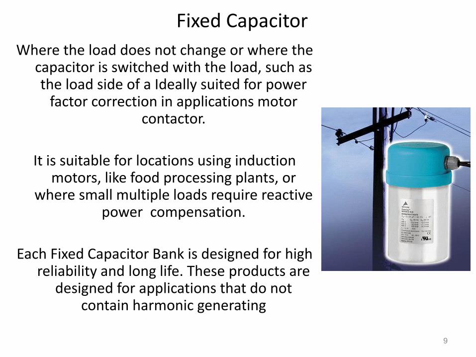
Fixed Capacitor
Where the load does not change or where the capacitor is switched with the load, such as the load side of a Ideally suited for power
factor correction in applications motor contactor.
It is suitable for locations using induction motors, like food processing plants, or
where small multiple loads require reactive power compensation.
Each Fixed Capacitor Bank is designed for high reliability and long life. These products are
designed for applications that do not contain harmonic generating
9
Switched Capacitor
It is suited for centralized power factor correction in applications where plant loading is constantly changing,
resulting in the need for varying amounts of reactive power. An advanced microprocessor-based reactive power controller
measures plant power factor via a single remote current transformer (included), and switches capacitor modules in and out of service to maintain a user-selected target power
factor. Typically applied at service entrance or near fluctuating
loads.
10
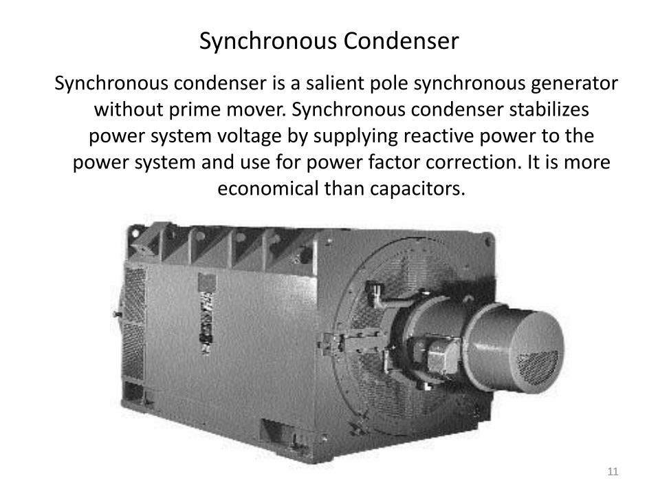
Synchronous Condenser
Synchronous condenser is a salient pole synchronous generator without prime mover. Synchronous condenser stabilizes
power system voltage by supplying reactive power to the power system and use for power factor correction. It is more
economical than capacitors.
11
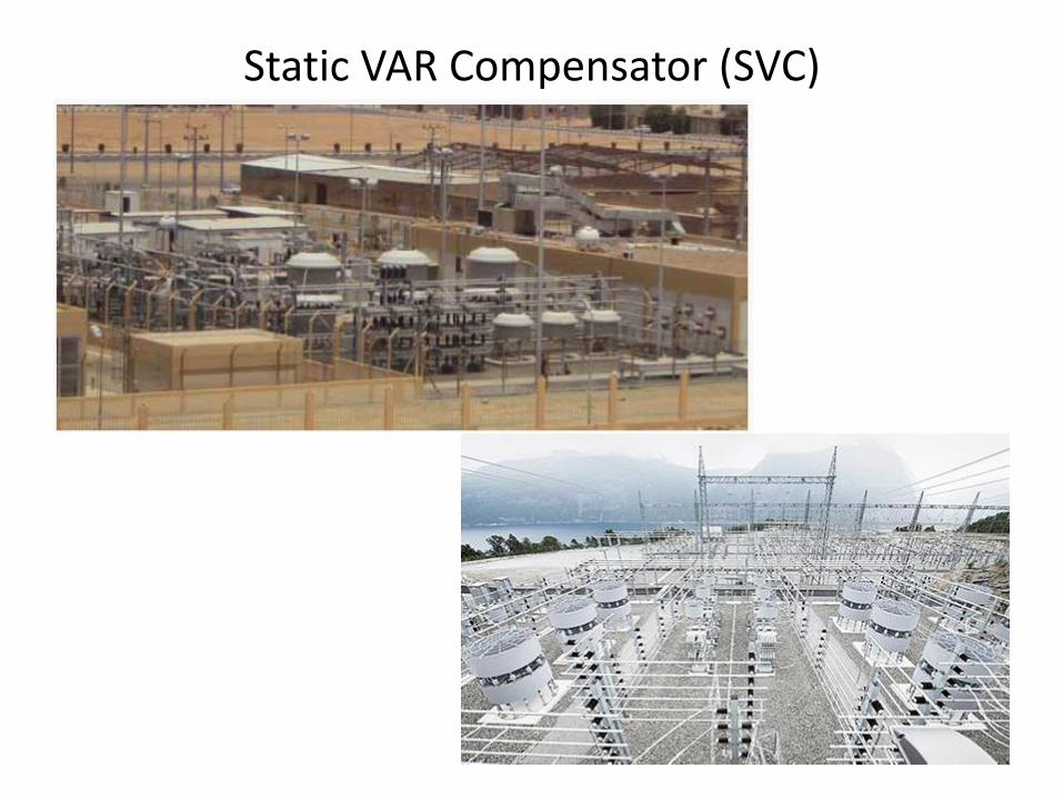
Static VAR Compensator (SVC)
The Static VAR Compensator (SVC) is a shunt device of the Flexible AC Transmission Systems (FACTS) family using power electronics to
control power flow and improve transient stability on power grids. The SVC regulates voltage at its terminals by controlling the amount of
reactive power injected into or absorbed from the power system. When system voltage is low, the SVC generates reactive power (SVC
capacitive). When system voltage is high, it absorbs reactive power (The variation
of reactive power is performed by switching three-phase capacitor banks and inductor banks connected on the secondary side of a
coupling transformer. Each capacitor bank is switched on and off by three thyristor switches (Thyristor Switched Capacitor or TSC).
Reactors are either switched on-off (Thyristor Switched Reactor or TSR) or phase-controlled (Thyristor Controlled Reactor or TCR).
12
Static VAR Compensator (SVC)
Static Synchronous Compensator (STATCOM)
The Static Synchronous Compensator (STATCOM) is a shunt device of the Flexible AC Transmission Systems (FACTS) family
using power electronics to control power flow and improve transient stability on power grids. The STATCOM regulates
voltage at its terminal by controlling the amount of reactive power injected into or absorbed from the power system.
When system voltage is low, the STATCOM generates reactive power (STATCOM capacitive).
When system voltage is high, it absorbs reactive power (STATCOM inductive).Similarly to the SVC the STATCOM can provide instantaneous and continuously variable reactive
power in response to grid voltage transients enhancing the grid voltage stability
14
STATIC SYNCHRONOUS COMPENSTOR (STATCOM)
The Static Synchronous Compensator (STATCOM) is a shunt device of the Flexible AC Transmission Systems (FACTS) family
using power electronics to control power flow and improve transient stability on power grids.
The STATCOM regulates voltage at its terminal by controlling the amount of reactive power injected into or absorbed from the
power system. When system voltage is low, the STATCOM
generates reactive power (STATCOM capacitive). STATCOM is GTO or IGBT based!
15
Basic types of FACTS Controllers
Series Controllers The series controller could be a variable impedance or a variable source both are power electronics based. In principle, all series
controllers inject voltage in series with the line. Shunt Controllers
The shunt controllers may be variable impedance connected to the line voltage causes a variable current flow hence represents
injection of current into the line. Combined Series-series Controllers
The combination could be separate series controllers or unified series-series controller-Interline Power Flow Controller.
Combined Series-shunt Controllers The combination could be separated series and shunt controllers
or a unified power flow controller
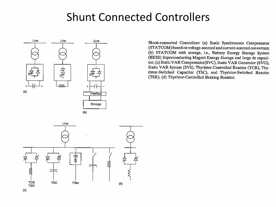
Shunt Connected Controllers
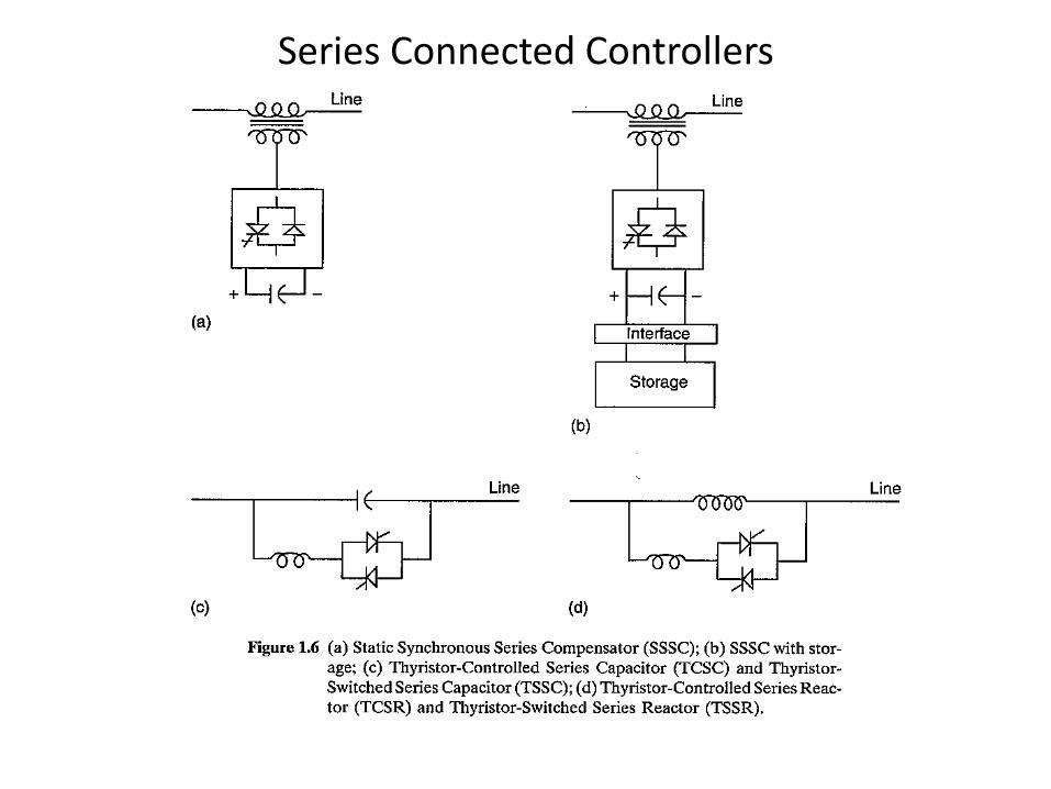
Series Connected Controllers
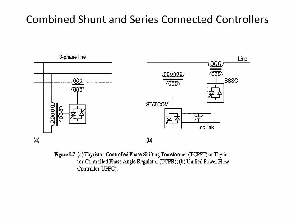
Combined Shunt and Series Connected Controllers
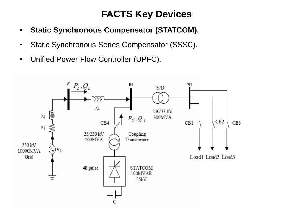
FACTS Key Devices
• Static Synchronous Compensator (STATCOM).
• Static Synchronous Series Compensator (SSSC).
• Unified Power Flow Controller (UPFC).
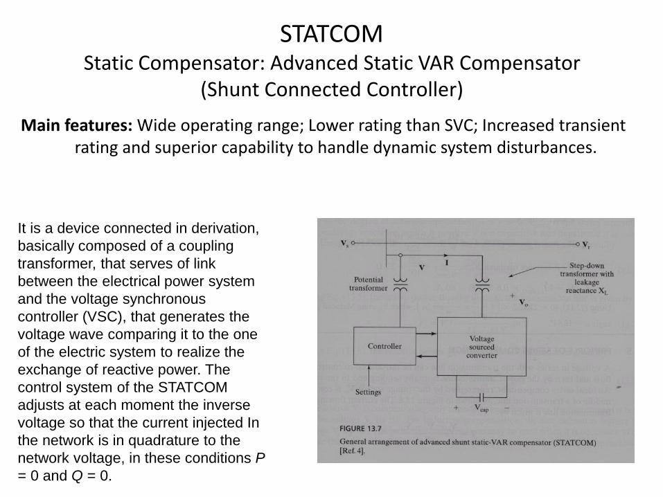
STATCOM Static Compensator: Advanced Static VAR Compensator
(Shunt Connected Controller)
Main features: Wide operating range; Lower rating than SVC; Increased transient rating and superior capability to handle dynamic system disturbances.
It is a device connected in derivation,
basically composed of a coupling
transformer, that serves of link
between the electrical power system
and the voltage synchronous
controller (VSC), that generates the
voltage wave comparing it to the one
of the electric system to realize the
exchange of reactive power. The
control system of the STATCOM
adjusts at each moment the inverse
voltage so that the current injected In
the network is in quadrature to the
network voltage, in these conditions P
= 0 and Q = 0.
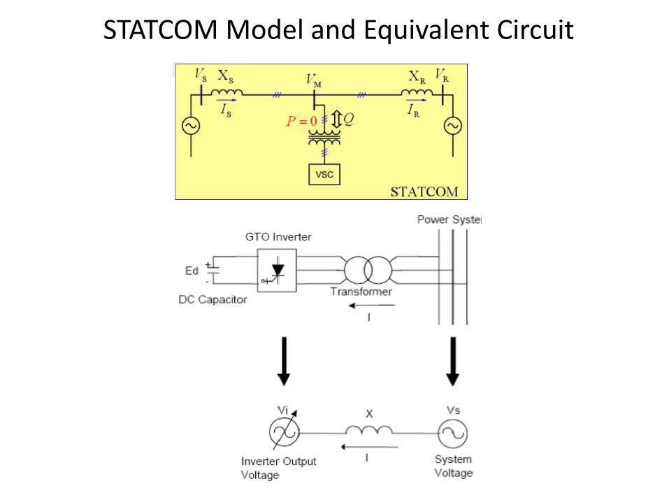
STATCOM Model and Equivalent Circuit