elements of a digital communication systemee.eng.usm.my/eeacad/mandeep/eee436/chapter1.pdf · 1...
TRANSCRIPT

1
ELEMENTS OF A DIGITAL COMMUNICATION SYSTEM
The analysis and design of digital communication systems.
Involves the transmission of information in digital form from a source that generates the information to one or more destinations.
1.1 ELEMENTS OF A DIGITAL COMMUNICATION SYSTEM Figure 1.1-1 illustrates the functional diagram and the basic elements of a digital communication system.
FIGURE 1.1-1 Basic elements of a digital communication system. The source output may be either an analog signal, such as an audio or video signal, or a digital signal, such as the output of a teletype machine, that is discrete in time and has a finite number of output characters. In a digital communication system, the messages produced by the source are converted into a sequence of binary digits.
2
The process of efficiently converting the output of either an analog or digital source into a sequence of binary digits is called source encoding or data compression. The sequence of binary digits from the source encod er, which we call the information sequence, is passed to the channel encoder. The purpose of the channel encoder is to introduce, in a controlled manner, some redundancy in the binary information sequence that can be used at the receiver to overcome the effects of noise and interference encountered in the transmission of the signal through the channel. This increase the reliability of the received data and improves the fidelity of the received signal. The binary sequence at the output of the channel encoder is passed to the digital modulator, which serves as the interface to the communication channel. Since nearly all the communication channels encountered in practice are capable of transmitting electrical signals (waveforms), the primary purpose of the digital modulator is to map the binary information sequence into signal waveforms. To elaborate on this point, let us suppose that the coded information sequence is to be transmitted one bit at a time at some uniform rate R bits per second (bits/s). The digital modulator may simply map the binary digit 0 into a waveform so(t) and the binary digit 1 into a waveform s, (t). In this manner, each bit from the channel encoder is transmitted separately. We call this binary modulation. Alternatively, the modulator may transmit 6 coded information bits at a time by using M = 2h distinct waveforms so(t), i = 0, 1, ..., M - 1, one waveform for each of the 26 possibl e b-bit sequences. We cal l thi s M-ary modulation (M > 2). Note that a new b-bit sequence enters the modulator every b/R seconds. Hence, when the channel bit rate R is fixed, the amount of time available to transmit one of the M waveforms corresponding to a b-bit sequence is b times the time period in a system that uses binary modulation.
3
The communication channel is the physical medium that is used to send the signal from the transmitter to the receiver. In wireless transmission, the channel may be the atmosphere (free space). On the other hand, telephone channels usually employ a variety of physical media, including wire lines, optical fiber cables, and wireless (microwave radio). Whatever the physical medium used for transmission of' the information, the essential feature is that the transmitted signal is corrupted in a random manner by a variety of possible mechanisms, such as additive thermal noise generated by electronic devices; man-made noise, e.g., automobile ignition noise; and atmospheric noise, e.g., electrical lightning discharges during thunderstorms. At the receiving end of a digital communication system, the digital demodulator processes the channel -corrupted transmitted waveform and reduces the waveforms to a sequence of numbers that represent estimates of the transmitted data symbols (binary or M -ary). This sequence of number s is passed to the channel decoder, which attempts to reconstruct the original information sequence from knowledge of the code used by the channel encoder and the redundancy contained in the received data. A measure of' how well the demodulator and decode r perform is the fre -quency with which errors occur in the decoded sequence. More precisely, the average probability of a bit-error at the output of the decoder is a measure of the performance of the demodulator decoder combination. In general, the probability of error is a function of the code characteristics, the types of waveforms used to transmit the information over the channel, the transmitter power, the characteristics of the channel (i.e., the amount Of noise, the Mature of the interference), and the method of' demodulation and decoding. The source decoder accepts the output sequence from the channel decoder and, from knowledge of the source encoding method used, attempts to reconstruct the original signal from tile source. Because of channel decoding errors and possible distortion introduced by the source encoder, and perhaps, the source decoder, the signal at the

4
output of the source decoder is an approximation to the original source output The difference or some function of the difference between the original signal and the reconstructed signal is a measure of the distortion introduced by the digital communication system.
1.2 COMMUNICATION CHANNELS AND THEIR CHARACTERISTICS The communication channel provides the connection between the transmitter and the receiver. The physical channel may be a pair of wires that carry the electrical signal, or an optical fiber that carries the information on a modulated light beam, or an underwater ocean channel in which the information is transmitted acoustically, or free space over which the information -bearing signal is radiated by use of an antenna. Other media that can be characterized as communication channels are data storage media, such as magnetic tape, magnetic disks, and optical disks. One common problem in signal transmission through any channel is additive noise. Additive noise is generated internally by components such as resistors and solid-state devices used to implement the communication system. This is sometimes called thermal noise . Other sources of noise and interference may arise externally to the system, such as interference from other users of the channel. When such noise and interference occupy the same frequency band as the desired signal, their effect can be minimized by the proper design of the transmitted signal and its demodulator at the receiver. Other types of signal degradations that may be encountered in transmission over the channel are signal attenuation, amplitude and phase distortion, and multipath distortion. The effects of noise may be minimized by increasing the power in the trans-mitted signal. However, equipment and other practical constraints limit the power level in the transmitted signal.

5
Another basic limitation is the available channel bandwidth. A bandwidth constraint is usually due to the physical limita tions of the medium and the electronic components used to implement the transmitter and the receiver. Wireline channels. The telephone network makes extensive use of wire lines for voice signa l transmission, as well as data and video transmission. Twisted pair wire lines and coaxial cable are basically guided electromagnetic channels that provide relatively modest bandwidths. Telephone wire generally used to connect a customer to a central office has a bandwidth of several hundred kilohertz (kHz).
6
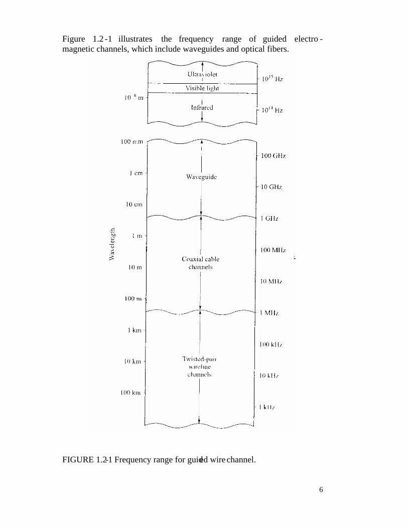
Figure 1.2 -1 illustrates the frequency range of guided electro -magnetic channels, which include waveguides and optical fibers.
FIGURE 1.2-1 Frequency range for guided wire channel.

7
Signals transmitted through such channels are distorted in both amplitude and phase and further corrupted by additive noise. Twisted-pair wireline channels are also prone to crosstalk interference from physically adjacent channels. Fiber-optic channels. Optical fibers offer the communication system designer a channel bandwidth that is several orders of magnitude larger than coaxial cable channels. The transmitter or modulator in a fiber -optic communication system is a light source , either a light -emitting diode (LED) or a laser. Information is transmitted by varying (modulating) the intensity of the light source with the message signal. The light propagates through the fiber as a light wave and is amplified periodically (in the case of digital transmission, it is detected and regenerated by repeaters) along the transmission path to compensate for signal attenuation. At the receiver, the light intensity is detected by a photodiode, whose output is an electrical signal that varies in direct proportion to the power of the light impinging on the photodiode. Sources of noise in fiber -optic channels are photodiodes and electronic amplifiers. Wireless electromagnetic channels. Electromagnetic energy is coupled to the propagation medium by an antenna which serves as the radiator. The physical size and the configuration of the antenna depend primarily on the frequency of operation. To obtain efficient radiation of electromagnetic energy, the antenna must be longer than, 1/10 of the wavelength. Consequently, a radio station transmitting in the amplitude-modulated (AM) frequency band, say at fc = 1 MHz [corresponding to a wavelength of λ = c/fc = 300 meters (m)], requires an antenna of at least 30 m.

8
FIGURE 1.2-2 Frequency range for wireless electromagnetic channels. The mode of propagation of electromagnetic waves in the atmosphere and in free space may be subdivided into three categories, namely, ground-wave propagation, sky-wave propagation, and line-of-sight (LOS) propagation.

9
In the very low frequency (VLF) and audio frequency bands, where the wavelengths exceed 10 km, the earth and the ionosphere act as a waveguide for electromagnetic wave propagation. In these frequency ranges, communication signals practically propagate around the globe. For this reason, these frequency bands are primarily used to provide navigational aids from shore to ships around the world. The channel bandwidths available in these frequency bands are relatively small (usually 1-10 percent of the center frequency), and hence the information that is transmitted through these channels is of relatively slow speed and generally confined to digital transmission. A dominant type of noise at these frequencies is generated from thunderstorm activity around the globe, especially in tropical regions. Interference results from the many users of these frequency bands.
FIGURE 1.2 -3 Illustration of ground-wave propagation Ground-wave propagation, as illustrated in Fig. 1.2-3, is the dominant mode of propagation for frequencies in the medium frequency (MF) band (0.3 -3 MHz). This is the frequency band used for AM broadcasting and maritime radio broadcasting. In AM broadcasting, the range with ground -wave propagation of even the more powerful radio stations is limited to about 150 km. Atmospheric noise, man-made noise, and thermal noise from electronic components at the receiver are dominant disturbances for signal transmission in the MF band.

10
Sky-wave propagation, as illustrated in Fig. 1.2-4, results from transmitted signals being reflected (bent or refracted) from the ionosphere, which consists of several layers of charged particles ranging in altitude from 50 to 400 km above the surface of the earth. During the daytime hours, the heating of the lower atmosphere by the sun causes the formation of the lower layers at altitudes below 120 km. These lower layers, especially the D-layer, serve to absorb frequencies below 2 MHz, thus severely limiting sky-wave propagation of AM radio broadcast. However, during the nighttime hours, the electron density in the lower layers of the ionosphere drops sharply and the frequency absorption that occurs during the daytime is significantly reduced. As a consequence, powerful AM radio broadcast stations can propagate over large distances via sky wave over the F-layer of the ionosphere, which ranges from 140 to 400 km above the surface of the earth.
FIGURE 1.2 -4 Illustration of sky-wave propagation. A frequently occurring problem with electroma gnetic wave propagation via sky wave in the high frequency (HF) range is signal multipath. Signal multipath occurs when the transmitted signal arrives at the receiver via multiple propagation paths at different delays.
11
It generally results in intersymbol interference it a digital communication system. Moreover, the signal components arriving via different propagation paths may add destructively, resulting in a phenomenon called signal fading, which most people have experienced when listening to a distant radio station at night when sky wave is the dominant propagation mode. Additive noise in the HF range is a combination of atmospheric noise and thermal noise. Sky-wave ionospheric propagation ceases to exist at frequencies above approximately 30 MHz, which is the end of the HF band. However, it is possible to have ionospheric scatter propagation at frequencies in the range 30-60 MHz, resulting from signal scattering from the lower ionosphere. It is also possible to communicate over distances of several hundred miles by use of tropospheric scattering at frequencies in the range 40-300 MHz. Troposcatter results from signal scattering due to particles in the atmosphere at altitudes of 10 miles or less. Generally, ionospheric scatter and tropospheri c scatter involve large signal propagation losses and require a large amount of transmitter power and relatively large antennas. Frequencies above 30 MHz propagate through the ionosphere with relatively little loss and make satellite and extraterrestria l communications possible. Hence, at frequencies in the very high frequency (VHF) hand and higher, the dominant mode of electromagnetic propagation is LOS propagation. For terrestrial communication systems, this means that the transmitter and receiver antennas must be in direct LOS with relatively little or no obstruction. For this reason, television stations transmitting in the VHF and ultra high frequency (UHF) ands mount their antennas on high towers to achieve a broad coverage area.

12
The dominant noise limiting the performance of a communication system in VHF and UHF ranges is thermal noise generated in the receiver front end and cosmic noise picked up by the antenna. At frequencies in the super high fre quency (SHE) band above 10 GHz, atmospheric conditions play a major role in signal propagation. For example, at 10 GHz, the attenuation ranges from about 0.003 decibels per kilometer (dB/km) in light rain to about 0.3 dB/km in heavy rain. At 100 GHz, the attenuation ranges from about 0.1 dB/km in light rain to about 6 dB/km in heavy rain. Hence, in this frequency range, heavy rain introduces extremely high propagation losses that can result in service outages (total breakdown in the communication system). At frequencies above the extremely high frequency (EHF) band, we have the infrared and visible light regions of the electromagnetic spectrum, which can be used to provide LOS optical communication in free space. To date, these frequency bands have been used in experimental communication systems, such as satellite -to-satellite links. Underwater acoustic channels. Electromagnetic waves do not propagate over long distances under water except at extremely low frequencies. The attenuation of electromagnetic waves in water can be expressed in terms of the skin depth, which is the distance a signal is attenuated by 1/e. For seawater, the skin depth δ = 250 / f where.f is expressed in Hz and δ is in m. For example, at 10 kHz, the skin depth is 2.5 m. In contrast, acoust ic signals propagate over distances of tens and even hundreds of kilo-meters.

13
An underwater acoustic channel is characterized as a multipath channel due to signal reflections from the surface and the bottom of the sea. Because of wave motion, the signal multipath components undergo time-varying propagation delays that result in signal fading. The sound velocity is nominally about 1500 m/s, but the actual value will vary either above or below the nominal value depending on the depth at which the signa l propagates. Ambient ocean acoustic noise is caused by shrimp, fish, and various mammals. Near harbors, there is also man-made acoustic noise in addition to the ambient noise. In spite of this hostile environment, it is possible to design and implemen t efficient and highly reliable underwater acoustic communication systems for transmitting digital signals over large distances. Storage channels. Magnetic tape, including digital audiotape and videotape, magnetic disks used for storing large amounts of computer data, optical disks used for computer data storage, and compact disks are examples of data storage systems that can be character ized as communication channels. The process of storing data on a magnetic tape or a magnetic or optical disk is equivalent to transmitting a signal over a telephone or a radio channel. The readback process and the signal processing involved in storage systems to recover the stored information are equivalent to the functions performed by a receiver in a telephone or radio communication system to recover the transmitted information. Additive noise generated by the electronic components and interference from adjacent tracks is generally present in the readback signal of a storage system, just as is the case in a telephone or a radio communication system.

14
The amount of data that can be stored is generally limited by the size of the disk or tape and the density (number of bits stored per square inch) that can be achieved by the write/read electronic systems and heads. Channel coding and modulation are essential components of a well-designed digital magnetic or optical storage system. In the readback process, the signal is demodulated and the added redundancy Introduced by the channel encoder is used to correct errors in the readback signal.
1.3 MATHEMATICAL MODELS FOR COMMUNICATION CHANNELS The mathematical model for the channel is used in the design of the channel encoder and modulator at the transmitter and the demodulator and channel decoder at the receiver. The additive noise channel. The simplest mathematical model for a communication channel is the additive noise channel, illustrated in Fig. 1.3 -1.
FIGURE 1.3-1 The additive noise channel In this model, the transmitted signal s(t) is corrupted by an additive random noise process n(t). Physically, the additive noise process may arise from electronic components and amplifiers at the receiver of the communication system or from interference encountered in transmission (as in the case of radio signal tran smission).
15
If the noise is introduced primarily by electronic components and amplifiers at the receiver, it may be characterized as thermal noise. This type of noise is characterized statistically as a Gaussian noise process. Hence, the resulting mathematical model for the channel is usually called the additive Gaussian noise channel. When the signal undergoes attenuation in transmission through the channel, the received signal is )()()( tntstr += a (1) where α is the attenuation factor The linear filter channel. In some physical Channels, such as wireline telephone channels, filters are used to ensure that the transmitted signals do not exceed specified bandwidth limitations and thus do not interfere with one another. Such Channels are generally characterized mathematically as linear filter channels with additive noise, as illustrated in Fig. 1.3 -2. Hence, if the channel input is the signal s(t), the channel output is the signal )()(*)()( tntctstr += (2) where c(t) is the impulse response of the linear filter and * denotes convolution.

16
FIGURE 1.3-2 The linear filter channel with additive noise.
FIGURE 1.3-3 Linear time-variant filter channel with additive noise. The linear tim e-variant filter channel. Physical channels such as underwater acoustic channels and ionospheric radio channels that result in time-variant multipath propagation of the transmitted signal may be characterized mathematically as time-variant linear filters. Such linear filters are characterized by a time-variant channel impulse response c(t ; t), where c(t ; t), is the response of the channel at time t due to an impulse applied at time t - t . Thus, t represents the "age" (elapsed-time) variable. The linear time-variant filter channel with additive noise is illustrated in Fig. 1.3-3. For an input signal s(t), the channel output signal is
(3)

17
Examples:

18
1.4 A HISTORICAL PERSPECTIVE IN "THE DEVELOPMENT OF DIGITAL COMMUNICATIONS
The electric telegraph was developed by Samuel Morse and was demonstrated in 1837. Morse devised the variable-length binary code in which letters of the English alphabet are repre sented by a sequence of dots and dashes (code words). Nearly 40 years later, in 1875. Emile Baudot devised a code for telegraphy in which every letter was encoded into fixed-length binary code words of length 5. In the Baudot code, binary code elements are of equal length and designated as mark and space. Nyquist (1924), who investigated the problem of determining the maximum signaling rate that can be used over a telegraph channel of a given bandwidth without inter-symbol interference. He formulated a model of a telegraph system in which a transmitted signal has the general form (1.6) where g(t) represents a basic pulse shape {an} is the binary data sequence of {±1} transmitted at a rate of 1/T bits/s. Nyquist set out to determine the optimum pulse shape that was band-limited to W Hz and maximized the bit rate under the constraint that the pulse caused no inter-symbol interference at the sampling time k/T, k = 0, ±1, ±2, .... His studies led him to conclude that the maximum pulse rate is 2W pulses/s. This rate is now called the Nyquist rule.

19
Moreover, this pulse rate can be achieved by using the pulses g(t) = (sin 2πWt)/ 2πWt. This pulse shape allows recovery of the data without inter-symbol interference at the sampling instants. The sampling theorem states that a signal of bandwidth W can be reconstructed from samples taken at the Nyquist rate of 2 W samples/s using the interpolation formula. (1.7) Another significant advance in the development of communications was the work of Kolmogorov (1939) and Wiener (1942), who considered the problem of estimating a desired signal waveform s(t) in the presence of additive noise n(t), based on observation of the received signal r(t) = s(t) + n(t). This problem arises in signal demodulation. Kolmogorov and Wiener determined the linear filter whose output is the best mean-square approximation to the desired signal s(r). The resulting filter is called the optimum linear (Kolmogorov-Wiener) filter-. Shannon formulated the basic problem of reliable transmission of information in statistical terms, using probabilistic models for information sources and communication channels. He also demonstrated that the effect of a transmitter power constraint, a bandwidth constraint, and additive noise can be associated with the channel and incorporated into a single parameter, called the c h an n e l c a p ac i t y . For example, in the case of an additive white (spectrally flat) Gaussian noise interference, an ideal band-limited channel of bandwidth W has a capacity C given by

20
(1.8)
where P is the average transmitted power No is the power spectra] density of the additive noise. The significance of the channel capacity is as follows: If the information rate R from the source is less than C (R < C) , then it is theoretically possible to achieve reliable (error-free) transmission through the channel by appropriate coding. If R > C, reliable transmission is not possible regardless of the amount of signal processing performed at the transmitter and receiver. Thus, Shannon established basic limits on communication of information and gave birth to a new field that is now called information t h e o r y .
21
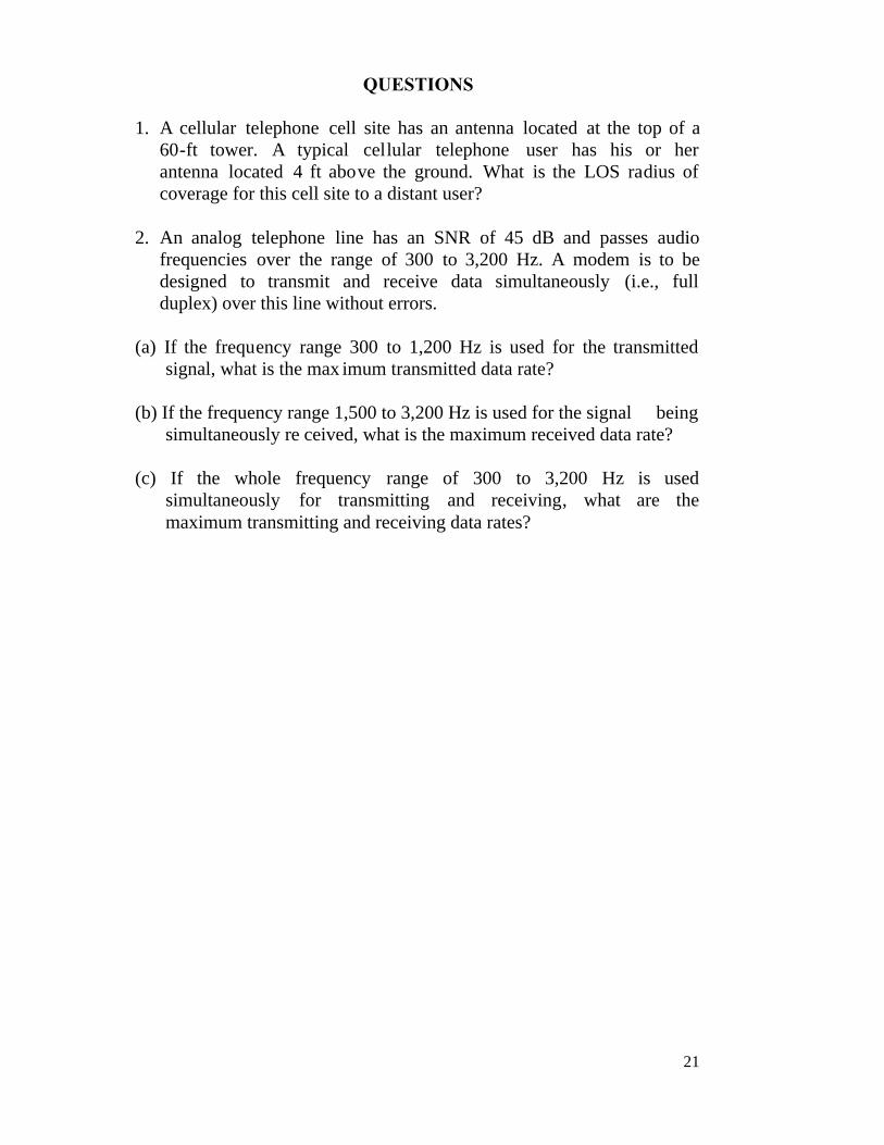
QUESTIONS
1. A cellular telephone cell site has an antenna located at the top of a 60-ft tower. A typical cellular telephone user has his or her antenna located 4 ft above the ground. What is the LOS radius of coverage for this cell site to a distant user?
2. An analog telephone line has an SNR of 45 dB and passes audio
frequencies over the range of 300 to 3,200 Hz. A modem is to be designed to transmit and receive data simultaneously (i.e., full duplex) over this line without errors.
(a) If the frequency range 300 to 1,200 Hz is used for the transmitted
signal, what is the max imum transmitted data rate? (b) If the frequency range 1,500 to 3,200 Hz is used for the signal being
simultaneously re ceived, what is the maximum received data rate? (c) If the whole frequency range of 300 to 3,200 Hz is used
simultaneously for transmitting and receiving, what are the maximum transmitting and receiving data rates?