electrostatic suspension system with sliding mode control
TRANSCRIPT
I. INTRODUCTION
The electrostatic gyroscope (ESG) is the most accurate gyro at present. Its random drift is very small, even 1 x deg/h, which is 2-3 orders smaller than other gyros, such as floated gyro, ring laser gyro, etc. The electrostatic suspension system (ESS) is one of the most important parts of the ESG. To some extent its performance will determine the accuracy and the reliability of the ESG. In fact, ESS is a noncontacting bearing. The design requirements on ESS may be concluded as follows [l]: 1) load capacity, 2) reliability, and 3) accuracy.
In a normal ESS, the basic control law is as follows.
U = U, - U, (1)
where, U is the suspension voltage, U, is the preload voltage, and U, is the control voltage.
preload voltage, because the maximum absolute value of U, must be less than U,. Otherwise, it is impossible for the ESS to operate. For example, if a load capacity up to 6g is required, the peak voltage of preload on the suspension electrode should be 772V for the ESG developed in the People’s Republic of China 121. In inertial surveying systems, however, the ESS bears only lg, (i.e., under gravity) for most of the working time. It is unfavorable to apply a high preload on the rotor over a long period of time, because the high preload will result in larger electrical disturbing torques and hence increase the drift error of the ESG. Moreover, the higher the preload voltage is, the larger the power consumption of ESS will be. Therefore, the preload voltage should be selected as low as possible.
Related to this problem, a lot of research works have been published, such as the two-mode preload [3], the adaptive bias [4], the multistage flight suspension [5], the automatic variation of preload between high g and low g, and the multistage and continuously variable preload [6], etc. Some comments on these schemes have been given in [2]. Here we introduce a new idea, the suspension with sliding mode control (SMC).
The load capacity of the ESS depends on its
Electrostatic Suspension System with Sliding Mode Control
W. Q. YANG
Y. S. ZHANG Tsinghua University People’s Republic of China
WO aspects must be considered in selecting the preload of electrostatic suspension system (ESS) for the electrostatic gyroscope (ESG), both the required load capacity and the tolerable electrical disturbing torqws exerted on the rotor. By meam of
sliding mode control (SMC), ESS may operate in three -des: 1)
two-sided linear suspensioq 2) single-sided nonlinear suspension, and 3) single-sided suspemion with nonlinearity compensation Therefore, a low preload can be selected for reducing both the electrical disturbing torques and the power consunption, meanwhile emuring the required load capacity. It has been proven by experiments that the ESS with 2g preload can bear overload acceleration up to 6g successfully.
Manuscript received March 25,1991; revised June 19, 1991.
IEEE Log No. 9104956.
Authors’ address: Dept. of Precision Instruments, Tsinghua University, Beijing 1ooo84, People’s Republic of China.
0018-9251/w$3.00 @ 1992 IEEE
11. IDEA OF SUSPENSION WITH SMC
Variable structure systems have been utilized for many years. In a variable structure system, new system properties can be obtained by composing a desired trajectory from the parts of trajectories of different structures by suitable switching logic. The trajectory obtained describes a new type of motion, the so-called sliding mode.
The operation mode of ESS may be varied. The key problem is how to combine these modes into a desired pattern. The basic idea of suspension with SMC is to enable the ESS to operate in three modes in terms of different overload acceleration.
IEEE TRANSACTIONS ON AEROSPACE AND ELECTRONIC SYSTEMS VOL. 28, NO. 2 APRIL 1992 605
__ _ _ _ _ ~- ni - 1 ~ - _ _ _ _ ~ -
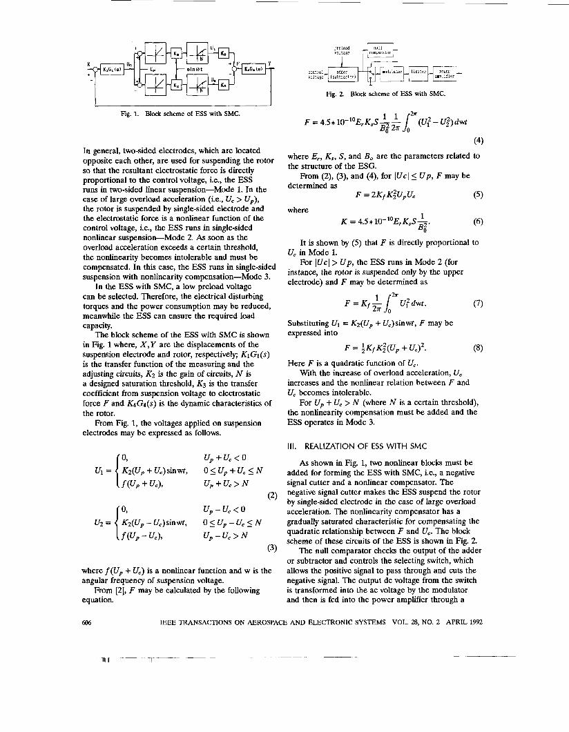
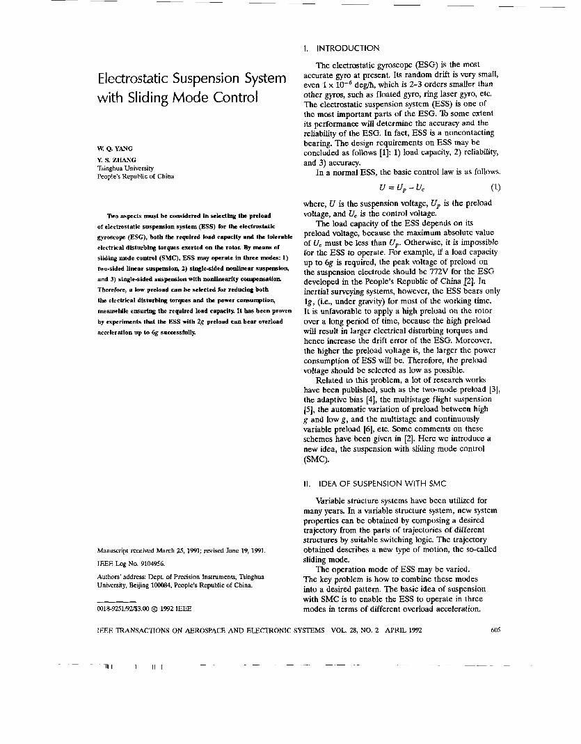
Fig. 1. Block scheme of ESS with SMC.
In general, two-sided electrodes, which are located opposite each other, are used for suspending the rotor so that the resultant electrostatic force is directly proportional to the control voltage, i.e., the ESS runs in two-sided linear suspension-Mode 1. In the case of large overload acceleration (i.e., U, > Up), the rotor is suspended by single-sided electrode and the electrostatic force is a nonlinear function of the control voltage, i.e., the ESS runs in single-sided nonlinear suspension-Mode 2. As soon as the overload acceleration exceeds a certain threshold, the nonlinearity becomes intolerable and must be compensated. In this case, the ESS runs in single-sided suspension with nonlinearity compensation-Mode 3.
In the ESS with SMC, a low preload voltage can be selected. Therefore, the electrical disturbing torques and the power consumption may be reduced, meanwhile the ESS can ensure the required load capacity.
The block scheme of the ESS with SMC is shown in Fig. 1 where, X,Y are the displacements of the suspension electrode and rotor, respectively; KIGl(s) is the transfer function of the measuring and the adjusting circuits, K2 is the gain of circuits, N is a designed saturation threshold, K3 is the transfer coefficient from suspension voltage to electrostatic force F and K4G4(s) is the dynamic characteristics of the rotor.
From Fig. 1, the voltages applied on suspension electrodes may be expressed as follows.
up+u,<o 0 5 Up + U, 5 N Up + U, > N
(2) Up - U, < Q 0 5 Up - U, 5 N Up - U, > N
(3)
where f(Up -k U,) is a nonlinear function and w is the angular frequency of suspension voltage.
From [2], F may be calculated by the following equation.
preload
Fig. 2 Block scheme of ESS with SMC.
F
(4)
where E,, K,, S, and Bo are the parameters related to the structure of the ESG.
From (2), (3), and (4), for lUcl 5 Up, F may be determined as
F = 2KfK;UpU, (5)
where 1 K = ~ . ~ * ~ o - ~ ~ E , K , s - .
B,2 It is shown by (5) that F is directly proportional to
For lUcl> Up, the ESS runs in Mode 2 (for U, in Mode 1.
instance, the rotor is suspended only by the upper electrode) and F may be determined as
i r2u
(7)
Substituting U, = K2(Up + U,)sinwt, F may be expressed into
F = iKfK;(Up + U,)2. (8)
Here F is a quadratic function of U,. With the increase of overload acceleration, U,
increases and the nonlinear relation between F and U, becomes intolerable.
For Up + U, > N (where N is a certain threshold), the nonlinearity compensation must be added and the ESS operates in Mode 3.
Ill. REALIZATION OF ESS WITH SMC
As shown in Fig. 1, two nonlinear blocks must be added for forming the ESS with SMC, i.e., a negative signal cutter and a nonlinear compensator. The negative signal cutter makes the ESS suspend the rotor by single-sided electrode in the case of large overload acceleration. The nonlinearity compensator has a gradually saturated characteristic for compensating the quadratic relationship between F and U,. The block scheme of these circuits of the ESS is shown in Fig. 2.
or subtractor and controls the selecting switch, which allows the positive signal to pass through and cuts the negative signal. The output dc voltage from the switch is transformed into the ac voltage by the modulator and then is fed into the power amplifier through a
The null comparator checks the output of the adder
606 IEEE TRANSACTIONS ON AEROSPACE AND ELECTRONIC SYSTEMS VOL. 28, NO. 2 APRIL 1992
~~ __ .___ - -~ n - Tr- __-
I' R 1-
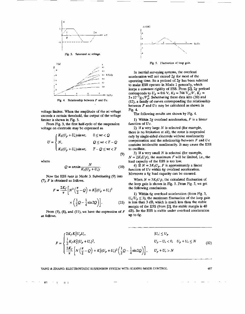
Fig. 3. Saturated ac voltage.
I
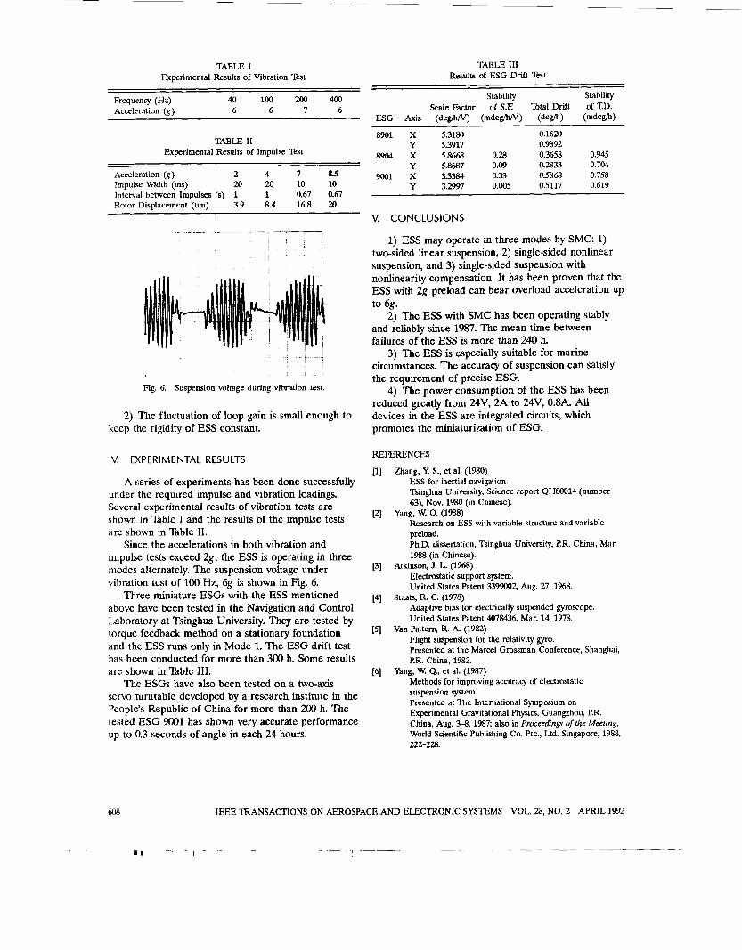
Fig. 4. Relationship between F and Uc.
voltage limiter. When the amplitude of the ac voltage exceeds a certain threshold, the output of the voltage limiter is shown in Fig. 3.
voltage on electrode may be expressed as
K2(Up + Uc)sinwt,
From Fig. 3, the first half-cycle of the suspension
0 5 wt < Q
Q 5 wt < T - Q
T - Q _< W t < T K2(Up + Uc)SinWt,
(9)
where
Now the ESS runs in Mode 3. Substituting (9) into (7), F is obtained as follows.
x (?Q 1 1 - zsin2Q)].
From (9, (S), and (ll), we have the expression of F as follows.
Fig. 5. Fluctuation of loop gain.
In inertial surveying systems, the overload acceleration will not exceed 2g for most of the operating time. So a preload of 2g has been selected to make ESS operate in Mode 1 generally, which keeps a constant rigidity of ESS. From [2], 2g preload corresponds to U, = 0.6 V, K2 = 744 V p / V , K f = 5*10-5gf/V;. Substituting these data into (10) and (12), a family of curves corresponding the relationship between I; and Uc may be calculated as shown in Fig. 4.
The following results are shown by Fig. 4.
1) Within 2g overload acceleration, F is a linear function of Uc.
2) If a very large N is selected (for example, there is no limitation at all), the rotor is suspended only by single-sided electrode without nonlinearity compensation and the relationship between F and U c contains intolerable nonlinearity. It may cause the ESS to oscillate.
N = 2K2Up), the maximum F will be limited, i.e., the load capacity of the ESS is too low.
function of Uc within 6g overload acceleration. Moreover a 6g load capacity can be ensured.
When N = 3K2Up, the calculated fluctuation of the loop gain is shown in Fig. 5. From Fig. 5, we get the following conclusions.
1) Within 6g overload acceleration (from Fig, 3, Uc/Up 5 3), the maximum fluctuation of the loop gain is less than 3 dB, which is much less than the stable margin of the ESS (from [2], the stable margin is 40 dB). So the ESS is stable under overload acceleration up to 6g.
3) If a very small N is selected (for example,
4) If N = 3&up, F is approximately a linear
YANG & ZHANG. ELECTROSTATIC SUSPENSION SYSTEM WITH SLIDING MODE CONTROL 607
W L E I Experimental Results of Vibration Test
Frequency (Eh) 40 100 200 400 Acceleration (g) 6 6 7 6
TABLE I1 Experimental Results of Impulse Test
Acceleration (g) 2 4 7 8.5
Interval between Impulses (s) 1 1 0.67 0.67 Rotor Displacement (U) 3.9 8.4 16.8 20
Impulse Width (ms) 20 20 10 10
.-
Fig. 6. Suspension voltage during vibration test.
2) The fluctuation of loop gain is small enough to keep the rigidity of ESS constant.
IV. EXPERIMENTAL RESULTS
A series of experiments has been done successfully under the required impulse and vibration loadings. Several experimental results of vibration tests are shown in Xible I and the results of the impulse tests are shown in Bble 11.
Since the accelerations in both vibration and impulse tests exceed 2g, the ESS is operating in three modes alternately. The suspension voltage under vibration test of 100 Hz, 6g is shown in Fig. 6.
Three miniature ESGs with the ESS mentioned above have been tested in the Navigation and Control Laboratory at Tsinghua University. They are tested by torque feedback method on a stationary foundation and the ESS runs only in Mode 1. The ESG drift test has been conducted for more than 300 h. Some results are shown in Bble 111.
The ESGs have also been tested on a two-axis servo turntable developed by a research institute in the People’s Republic of China for more than 200 h. The tested ESG 9001 has shown very accurate performance up to 0.3 seconds of angle in each 24 hours.
TABLE 111 Results of ESG Drift Test
Stability Stability Scale Factor of S.E Total Drift of T.D.
ESG A x i s (deglhw) (mdeglhlV) (de@) (mdegh)
8901 X 5.3180 0.1620 Y 5.3917 0.9392
8904 x 5.8668 0.28 0.3658 0.945 Y 5.8687 0.09 0.2833 0.704
9001 x 3.3384 0.33 0.5868 0.758 0.005 0.5117 0.619 Y 3.2997
V. CONCLUSIONS
1) ESS may operate in three modes by SMC: 1) two-sided linear suspension, 2) single-sided nonlinear suspension, and 3) single-sided suspension with nonlinearity compensation. It has been proven that the ESS with 2g preload can bear overload acceleration up to 6g.
2) The ESS with SMC has been operating stably and reliably since 1987. The mean time between failures of the ESS is more than 240 h.
3) The ESS is especially suitable for marine circumstances. The accuracy of suspension can satisfy the requirement of precise ESG.
reduced greatly from 24V, 2A to 24V, 0.8A. All devices in the ESS are integrated circuits, which promotes the miniaturization of ESG.
4) The power consumption of the ESS has been
REFERENCES
[l] Zhang, Y. S., et al. (1980) ESS for inertial navigation. Tsinghua University, Science report QH80014 (number 63), Nov. 1980 (in Chinese).
Research on ESS with variable structure and variable preload. Ph.D. dissertation, Tsinghua University, P.R. China, Mar. 1988 (in Chinese).
[3] Atkinson, J. L. (1968) Electrostatic support system. United States Patent 3399002, Aug. 27, 1%8.
Adaptive bias for electrically suspended gyroscope. United States Patent 4078436, Mar. 14, 1978.
Flight suspension for the relativity gyro. Presented at the Marcel Grossman Conference, Shanghai, P.R. China, 1982.
Yang, W. Q., et al. (1987) Methods for improving accuraq of electrostatic suspension system. Presented at The International Symposium on Experimental Gravitational Physics, Guangzhou, P.R. China, Aug. 3-8, 1987; also in Proceedings of the Meeting, World Scientific Publishing Co. Pte., Ltd. Singapore, 1988, 222-228.
[2] Yang, W. Q. (1988)
[4] Staats, R. C. (1978)
[5] Van Pattern, R. A. (1982)
[6]
608 IEEE TRANSACTIONS ON AEROSPACE AND ELECTRONIC SYSTEMS VOL. 28, NO. 2 APRIL 1992
___. ___ ~ ____ _- ___ - i r - - __ - 111
1
W. Q. Yang was born in Caoxian, Shandong Province, People’s Republic of China on November 7, 1956. He received the B.S. degree in industrial instrumentation and automation in 1982, the M.S. degree in theory and application of automatic control in 1985, and the Ph.D. degree in precision instrument in 1988 from Tsinghua University, Beijing, People’s Republic of China.
lecturer in the Department of Precision Instruments at Tsinghua University. His research interests are automatic control systems, electrostatic gyro and inertial technology.
Ph.D. Dissertation in 1988 from Tsinghua University. He is a member of the Chinese Society of Inertial Technology.
Since 1988, he has been with the Navigation and Control Laboratory and is a
Dr. Yang acquired the title of the Excellent Graduate in 1982 and the Excellent
Y. S. Zhang was born in Shanghai, China in 1929. He received the B.S. degree in mechanical engineering from Tsinghua University, Beijing, People’s Republic of China, and the Candidate of Technical Science in instrumentation from Moscow Bauman Bchnical University in 1950 and 1957, respectively.
Since 1958 he has been with the Department of Automatic Control, Tsinghua University and was the Director of the Navigation and Control Laboratory. Currently he is Professor of Navigation and Control Systems in the Department of Precision Instruments, Tsinghua University and is involved in the design and development of electrostatically suspended gyroscope and ring laser gyroscope. His research interests are in the fields of inertial navigation systems, optimal estimation, and inertial sensors.
He is Vice President of the Chinese Society of Inertial Technology.
609 YANG & ZHANG: ELECTROSTATIC SUSPENSION SYSTEM WITH SLIDING MODE CONTROL
. . .-