electronic water level gauge installation, operation and ... · electronic water level gauge...
TRANSCRIPT

Electronic Water Level Gauge
Installation, Operation And Maintenance of
Aquarian 1000Plus
FOSSIL POWER SYSTEMS INC. 10 Mosher Drive Dartmouth, NS Canada B3B 1N5 PH# (902) 468-4701 ext 720 FAX# (902) 468-2323 www.fossil.ca

i
Aquarian 1000Plus
Instruction Manual 9340-1001
Last Modified: May 10, 2006
Copyright © 2002 Fossil Steam Technologies Inc. All rights reserved. All trademarks referenced herein are property of their respective corporation.
The information contained herein is subject to change without notice.
ii
About this Manual
This instruction manual describes the architecture and operation of the Aquarian 1000 Plus as supplied by Fossil Power Systems Inc.
Although care was exercised to make this Manual specific and complete, it is not intended that it and its accompanying equipment manuals should provide for all potential operating and maintenance conditions. It must be recognized that no amount of written instruction can replace intelligent thinking and reasoning on the part of qualified personnel. It is the responsibility of these personnel to become completely familiar with the mechanical, electrical and control systems involved, including their characteristics and performance under various operating conditions.
This knowledge can be obtained through the basic information provided in this manual, supplemented by advice and recommendations from this Company’s field agents and by actual experience.
Operation, maintenance and performance of any equipment not furnished by this Company are the sole responsibility of others.
The nature of the electronics, the harsh operation environment and the potential hazards associated with live steam require that only qualified personnel install and maintain the equipment.
iii
Table of Contents1 INTRODUCTION.................................................................................................................1
2 PACKAGING ........................................................................................................................2
3 INSTALLATION ..................................................................................................................2 3.1 LOCATION OF THE ELECTRONICS..............................................................................................2 3.2 PRESSURE VESSEL....................................................................................................................3 3.2.1. FREEZE DAMAGE PRECAUTIONS ...........................................................................................4 3.3 PROBES ....................................................................................................................................4 3.4 WIRING ....................................................................................................................................5
3.4.1 At the Probes ..............................................................................................................5 3.4.2 At The Electronic Module...........................................................................................5
3.5 CONTROL OUTPUTS..................................................................................................................6 3.5.1 Detection Outputs .......................................................................................................6 3.5.2 Electronics Fault Output ............................................................................................6 3.5.3 Level Fault Output......................................................................................................6
4 START-UP AND OPERATION ..........................................................................................6 4.1 INDICATING LIGHTS .................................................................................................................6 4.2 PRESSURE VESSEL....................................................................................................................6 4.3 SENSITIVITY CONTROL.............................................................................................................7 4.4 SYSTEM MONITOR....................................................................................................................8
4.4.1 Power Supply Fault ....................................................................................................8 4.4.2 Clock Fault .................................................................................................................8 4.4.3 Continuity (Open Circuit)...........................................................................................8 4.4.4 Short Circuit ...............................................................................................................9 4.4.5 Level Error .................................................................................................................9
5 DETECTION THEORY.......................................................................................................9
6 MAINTENANCE ................................................................................................................10 6.1 PRESSURE VESSEL..................................................................................................................10 6.2 PROBES ..................................................................................................................................10
6.2.1 Probe Removal .........................................................................................................10 6.2.2 Probe Inspection.......................................................................................................10 6.2.3 Probe Installation .....................................................................................................11
7 SPARE PARTS....................................................................................................................12 7.1 INDIVIDUAL PART LIST ..........................................................................................................12

iv
8 SPECIFICATIONS .............................................................................................................13
9 AVAILABLE OPTIONS ....................................................................................................14
v
List of Figures Figure 1 - Typical Type "A" Probe Connector .................................................................................3 Figure 2 - Typical 1-1/2" Tee Probe Connector................................................................................4 Figure 3 - Probe assembly ................................................................................................................5 Figure 4 - Aquarian 1000 Plus System Wiring...............................................................................15 Figure 5 - Face Plate Label .............................................................................................................16 Figure 6 - Jumper Settings ..............................................................................................................17

1
1 INTRODUCTION
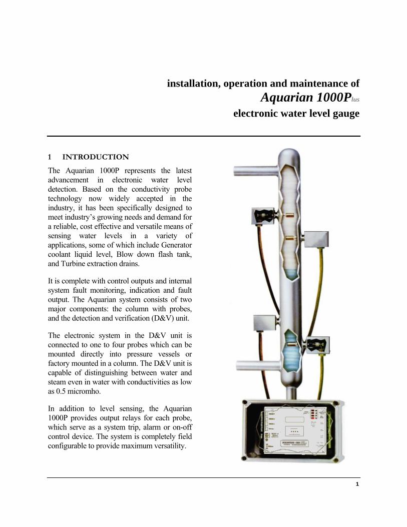
The Aquarian 1000P represents the latest advancement in electronic water level detection. Based on the conductivity probe technology now widely accepted in the industry, it has been specifically designed to meet industry’s growing needs and demand for a reliable, cost effective and versatile means of sensing water levels in a variety of applications, some of which include Generator coolant liquid level, Blow down flash tank, and Turbine extraction drains.
It is complete with control outputs and internal system fault monitoring, indication and fault output. The Aquarian system consists of two major components: the column with probes, and the detection and verification (D&V) unit.
The electronic system in the D&V unit is connected to one to four probes which can be mounted directly into pressure vessels or factory mounted in a column. The D&V unit is capable of distinguishing between water and steam even in water with conductivities as low as 0.5 micromho.
In addition to level sensing, the Aquarian 1000P provides output relays for each probe, which serve as a system trip, alarm or on-off control device. The system is completely field configurable to provide maximum versatility.
installation, operation and maintenance of
Aquarian 1000Plus
electronic water level gauge
Aquarian 1000 Plus Instruction Manual Fossil Power Systems Inc.
2
Each Aquarian 1000P system includes one detection/verification center and a maximum of four conductivity probes with related hardware.
The drawings supplied for each installation specifies the tapping point spacing on the pressure vessel, the number of probes and their positions.
Prior to performing any work, personnel responsible for the installation of the system should read these instructions and become familiar with the unit.
2 PACKAGING
The Aquarian 1000 Plus is packed in one box weighing up to 13 lb (6 Kg). The column, if one is supplied, is normally shipped on a wooden pallet. Prior to installing this equipment, clean all packing material from around the unit and inspect for any damage that may have occurred during shipment.
The purchaser must file any claims for loss or damage with the carrier. The manufacturer, on request, will furnish a copy of the bill of lading and freight bill if occasion to file a claim arises.
3 INSTALLATION
3.1 Location of the Electronics
Water with low conductivity requires a higher sensitivity. The highest sensitivity limits the cable distance between probe and electronic module to 65 feet (20m). The intermediate sensitivity places an upper limit of 165 feet (50m) on the cable distance. The lowest sensitivity allows the cable distance to be up to 500 feet (152m). A plug-in module permits
selection of the conductivity range of the unit. The highest conductivity mode should be used where possible. The coolest, most accessible location for mounting the electronics is preferred.
Aquarian 1000 Plus Instruction Manual Fossil Power Systems Inc.
3
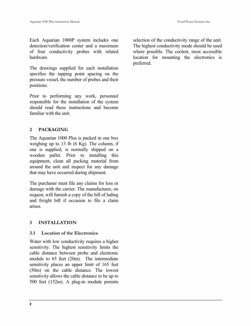
3.2 Pressure Vessel
Reference: • Figure 1 - Typical Type "A" Probe Connector • Figure 2 - Typical 1-1/2" Tee Probe Connector
If a pressure vessel is not supplied with the Aquarian 1000 Plus, two types of port receptacles are available:
• Type A (½" male Socket Weld) is for welding directly into a column or pressure vessel.
• The 1½" male Socket Weld is for welding into a 1½" ANSI 3000 lb Tee.
IMPORTANT Consult the factory if conditions require the use of other types of fittings or special mounting configurations. All welding should be done in accordance with approved procedures as required by applicable specifications. Isolation and blowdown valves should be selected and installed as outlined in
the latest edition of the ASME Power Boiler Code, Section 1, and be capable of tight shut-off.
Pressure vessels with two pressure ratings are available - a 2000 psi design and a 3000 psi design.
The fittings on steam generators of lower pressure usually have a lesser rating. As a result, the rating of the package is governed by the lowest rating of any one of the fittings. Outside applications require a weather shield.
On columns with full-length probe covers, the metal probe shields should be removed and remain off until the system is placed in service and a satisfactory inspection of all the probes and the associated wiring is completed.
All screws must be tightened and reinstalled if removed.
Figure 1 - Typical Type "A" Probe Connector

Aquarian 1000 Plus Instruction Manual Fossil Power Systems Inc.
4
An individual probe housing can be installed after the fitting has been welded in place. If you receive the probe housing assembly attached to the probe and fitting, remove the probe and housing prior to welding the fitting in place. The probe housing can be installed by removing the cover and placing the bracket (L shaped piece) over the fitting and installing the retaining ring to secure the bracket in place. Refer to Section II.4 to install the probe and Swagelok nut. The cover should remain off until the system is in service and a satisfactory inspection of the probe and the associated wiring is completed. If the housing is damaged and cannot be properly secured, it may cause a short circuit and must be replaced.
3.2.1. Freeze Damage Precautions
Installations and locations that may expose the pressure vessel column to low temperatures must take precautions to prevent water in the column from freezing. Water that freezes in
the pipe column could damage the probes. Several options to prevent damage include: protecting the column with a heated enclosure, draining water from the column when the boiler is shutdown, and installing insulation with heat tracing. The column junction box should not be insulated since the wire connected to the electronics could be damaged.
3.3 Probes
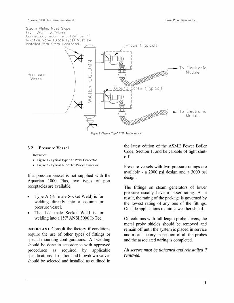
IMPORTANT The two probe hex head nuts located on the post used for the electrical connection have been pre-torqued to exact specification prior to shop testing. If the hex head nuts are inadvertently loosened, the probe must be replaced. Probes are supplied fully assembled. Probe receptacles on the pressure vessel are Swagelok fittings.
To ensure the probes remain clean, mount the receptacles such that the probes are exposed to
Figure 2 - Typical 1-1/2" Tee Probe Connector
Aquarian 1000 Plus Instruction Manual Fossil Power Systems Inc.
5
mild fluid circulation. Do not locate the probes in high velocity steam or water. Probes may be located horizontally or vertically with the electrical connection up.
Figure 3 - Probe assembly
If it is required to remove a Probe, then refer to Section 6.2 for information on removal, inspection and re-installation.
3.4 Wiring
CAUTION Before making any connections, make sure that the power source to be used is isolated by use of the appropriate circuit breakers and switches so that no work is being performed with "live wires". Before making any wire connections to the electronic module, holes must be drilled in the bottom panel of the module for the appropriate conduit connectors being used. Remove the electronics from the module when drilling the panel.
All wiring should be in accordance with applicable national and local codes by qualified personnel.
3.4.1 At the Probes
Reference: • Figure 4 - Aquarian 1000 Plus System Wiring
If the Aquarian is purchased without column or junction box, then it will be shipped with 3 feet of three-conductor fiberglass braided wire per probe. This is for connection to the probe
in the high temperature area. Ring lugs are supplied for fitting to a 0.190 in (5 mm) post. If an alternate lug is used, it should be nickel-plated. Two-conductor wire is supplied when a junction box is ordered with an optional column.
Each electronic module can handle the input from a maximum of four probes. Each probe input to the module can have up to three wires, one for probe, one for ground and one for optional continuity.
IMPORTANT The ring tongue crimp terminal is to be inserted on the probe terminal post between the thumbscrew and the two hex head nuts.
Do not loosen the two hex head nuts. Do not use excessive force to tighten the thumbscrew.
The probe ground wire is to be connected to the ground screw provided in the probe cover.
These wires should be run to an appropriate junction box. The wire connecting the probes to the electronic module from the junction box should be shielded 18 AWG or 20 AWG stranded, and either tin plated or silver plated copper. UNPLATED COPPER WIRE SHOULD NOT BE USED.
3.4.2 At The Electronic Module
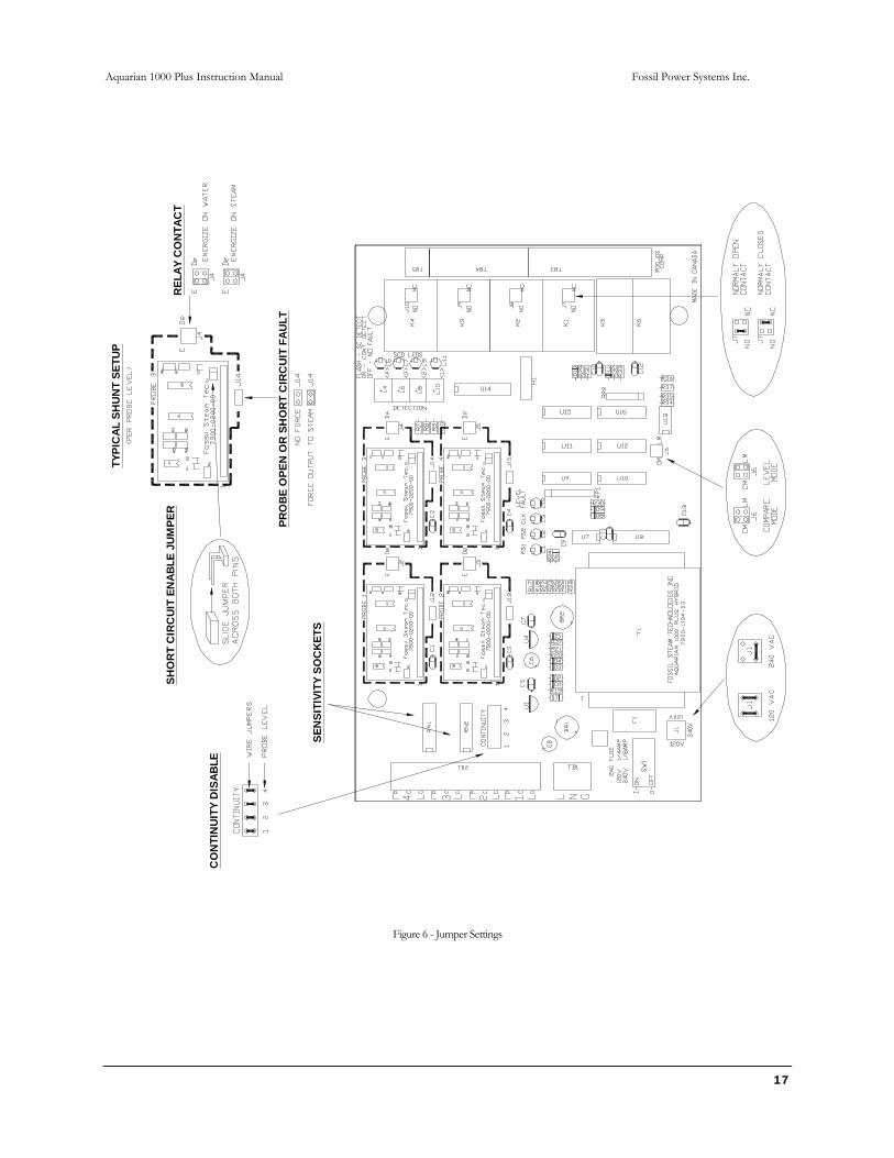
Reference: • Figure 6 - Jumper Settings
For reliable operation, a power source with the following requirements is necessary.
120 VAC or optional 240 VAC Single Phase, 50/60 Hz ¼ Amp / ⅛ Amp
Aquarian 1000 Plus Instruction Manual Fossil Power Systems Inc.
6
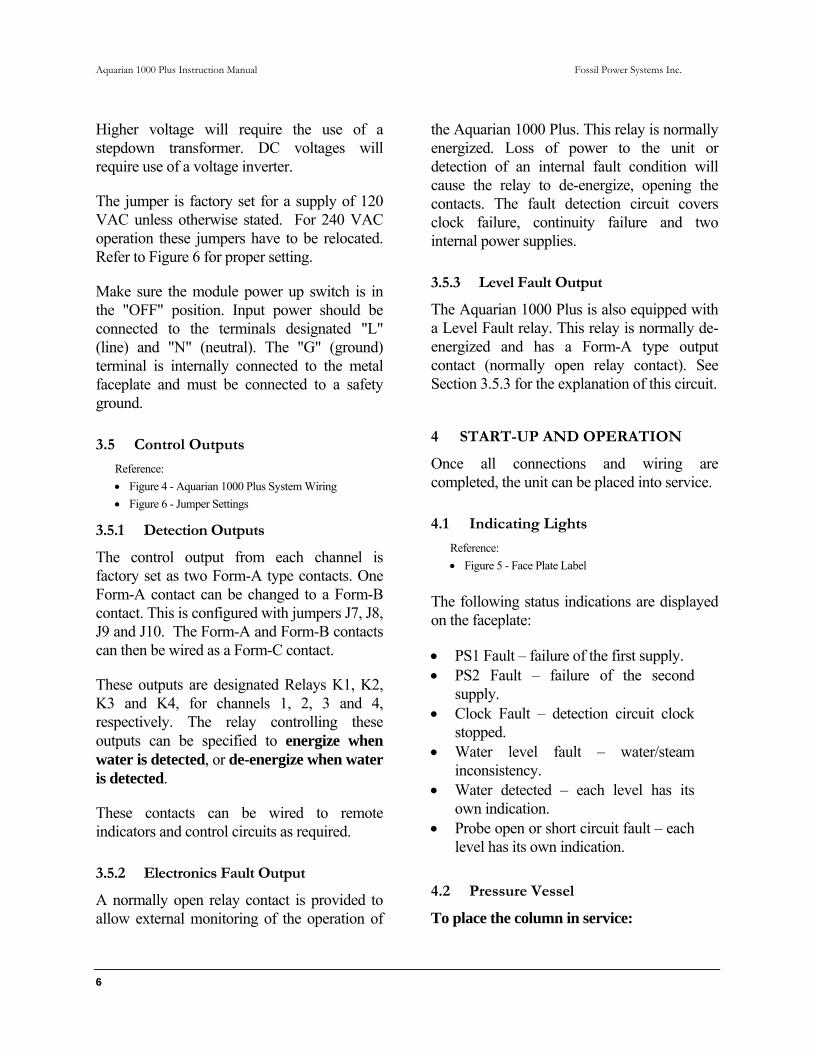
Higher voltage will require the use of a stepdown transformer. DC voltages will require use of a voltage inverter.
The jumper is factory set for a supply of 120 VAC unless otherwise stated. For 240 VAC operation these jumpers have to be relocated. Refer to Figure 6 for proper setting.
Make sure the module power up switch is in the "OFF" position. Input power should be connected to the terminals designated "L" (line) and "N" (neutral). The "G" (ground) terminal is internally connected to the metal faceplate and must be connected to a safety ground.
3.5 Control Outputs
Reference: • Figure 4 - Aquarian 1000 Plus System Wiring • Figure 6 - Jumper Settings
3.5.1 Detection Outputs
The control output from each channel is factory set as two Form-A type contacts. One Form-A contact can be changed to a Form-B contact. This is configured with jumpers J7, J8, J9 and J10. The Form-A and Form-B contacts can then be wired as a Form-C contact.
These outputs are designated Relays K1, K2, K3 and K4, for channels 1, 2, 3 and 4, respectively. The relay controlling these outputs can be specified to energize when water is detected, or de-energize when water is detected.
These contacts can be wired to remote indicators and control circuits as required.
3.5.2 Electronics Fault Output
A normally open relay contact is provided to allow external monitoring of the operation of
the Aquarian 1000 Plus. This relay is normally energized. Loss of power to the unit or detection of an internal fault condition will cause the relay to de-energize, opening the contacts. The fault detection circuit covers clock failure, continuity failure and two internal power supplies.
3.5.3 Level Fault Output
The Aquarian 1000 Plus is also equipped with a Level Fault relay. This relay is normally de-energized and has a Form-A type output contact (normally open relay contact). See Section 3.5.3 for the explanation of this circuit.
4 START-UP AND OPERATION
Once all connections and wiring are completed, the unit can be placed into service.
4.1 Indicating Lights
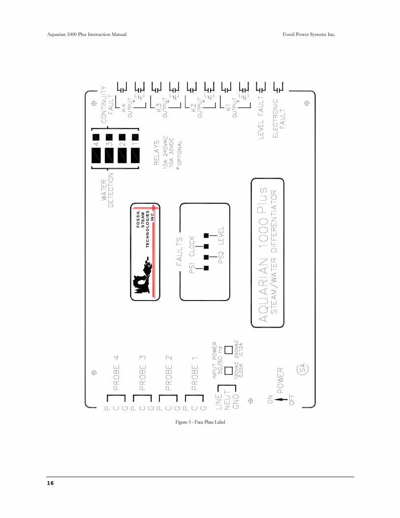
Reference: • Figure 5 - Face Plate Label
The following status indications are displayed on the faceplate:
• PS1 Fault – failure of the first supply. • PS2 Fault – failure of the second
supply. • Clock Fault – detection circuit clock
stopped. • Water level fault – water/steam
inconsistency. • Water detected – each level has its
own indication. • Probe open or short circuit fault – each
level has its own indication. 4.2 Pressure Vessel
To place the column in service:
Aquarian 1000 Plus Instruction Manual Fossil Power Systems Inc.
7
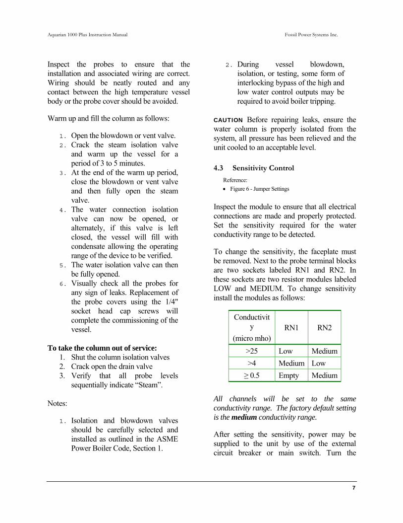
Inspect the probes to ensure that the installation and associated wiring are correct. Wiring should be neatly routed and any contact between the high temperature vessel body or the probe cover should be avoided.
Warm up and fill the column as follows:
1. Open the blowdown or vent valve. 2. Crack the steam isolation valve
and warm up the vessel for a period of 3 to 5 minutes.
3. At the end of the warm up period, close the blowdown or vent valve and then fully open the steam valve.
4. The water connection isolation valve can now be opened, or alternately, if this valve is left closed, the vessel will fill with condensate allowing the operating range of the device to be verified.
5. The water isolation valve can then be fully opened.
6. Visually check all the probes for any sign of leaks. Replacement of the probe covers using the 1/4" socket head cap screws will complete the commissioning of the vessel.
To take the column out of service:
1. Shut the column isolation valves 2. Crack open the drain valve 3. Verify that all probe levels
sequentially indicate “Steam”. Notes:
1. Isolation and blowdown valves should be carefully selected and installed as outlined in the ASME Power Boiler Code, Section 1.
2. During vessel blowdown, isolation, or testing, some form of interlocking bypass of the high and low water control outputs may be required to avoid boiler tripping.
CAUTION Before repairing leaks, ensure the water column is properly isolated from the system, all pressure has been relieved and the unit cooled to an acceptable level.
4.3 Sensitivity Control
Reference: • Figure 6 - Jumper Settings
Inspect the module to ensure that all electrical connections are made and properly protected. Set the sensitivity required for the water conductivity range to be detected.
To change the sensitivity, the faceplate must be removed. Next to the probe terminal blocks are two sockets labeled RN1 and RN2. In these sockets are two resistor modules labeled LOW and MEDIUM. To change sensitivity install the modules as follows:
Conductivity
(micro mho) RN1 RN2
>25 Low Medium>4 Medium Low ≥ 0.5 Empty Medium
All channels will be set to the same conductivity range. The factory default setting is the medium conductivity range.
After setting the sensitivity, power may be supplied to the unit by use of the external circuit breaker or main switch. Turn the
Aquarian 1000 Plus Instruction Manual Fossil Power Systems Inc.
8
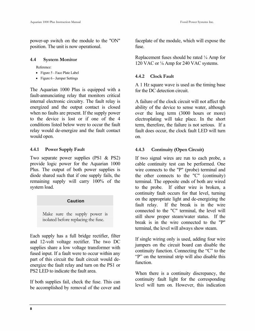
power-up switch on the module to the "ON" position. The unit is now operational.
4.4 System Monitor
Reference: • Figure 5 - Face Plate Label • Figure 6 - Jumper Settings
The Aquarian 1000 Plus is equipped with a fault-annunciating relay that monitors critical internal electronic circuitry. The fault relay is energized and the output contact is closed when no faults are present. If the supply power to the device is lost or if one of the 4 conditions listed below were to occur the fault relay would de-energize and the fault contact would open.
4.4.1 Power Supply Fault
Two separate power supplies (PS1 & PS2) provide logic power for the Aquarian 1000 Plus. The output of both power supplies is diode shared such that if one supply fails, the remaining supply will carry 100% of the system load.
Caution
Make sure the supply power is isolated before replacing the fuse.
Each supply has a full bridge rectifier, filter and 12-volt voltage rectifier. The two DC supplies share a low voltage transformer with fused input. If a fault were to occur within any part of this circuit the fault circuit would de-energize the fault relay and turn on the PS1 or PS2 LED to indicate the fault area.
If both supplies fail, check the fuse. This can be accomplished by removal of the cover and
faceplate of the module, which will expose the fuse.
Replacement fuses should be rated ¼ Amp for 120 VAC or ⅛ Amp for 240 VAC systems.
4.4.2 Clock Fault
A 1 Hz square wave is used as the timing base for the DC detection circuit.
A failure of the clock circuit will not affect the ability of the device to sense water, although over the long term (3000 hours or more) electroplating will take place. In the short term, therefore, the failure is not serious. If a fault does occur, the clock fault LED will turn on.
4.4.3 Continuity (Open Circuit)
If two signal wires are run to each probe, a cable continuity test can be performed. One wire connects to the "P" (probe) terminal and the other connects to the "C" (continuity) terminal. The opposite ends of both are wired to the probe. If either wire is broken, a continuity fault occurs for that level, turning on the appropriate light and de-energizing the fault relay. If the break is in the wire connected to the "C" terminal, the level will still show proper steam/water status. If the break is in the wire connected to the "P" terminal, the level will always show steam.
If single wiring only is used, adding four wire jumpers on the circuit board can disable the continuity function. Connecting the “C” to the “P” on the terminal strip will also disable this function.
When there is a continuity discrepancy, the continuity fault light for the corresponding level will turn on. However, this indication

Aquarian 1000 Plus Instruction Manual Fossil Power Systems Inc.
9
will automatically be disabled if a clock failure occurs.
The detection output can be forced to the steam state whenever an open or short (Section 4.4.4) circuit fault is active. Place shunts on J12, J13, J14 and J15 to enable this feature. Both faults will be affected by the jumper placement.
4.4.4 Short Circuit
This feature is normally shipped from the factory in the disabled state. Each level detection circuit is equipped with a jumper to enable the short circuit feature. Normally, systems are shipped with a shunt placed on only one pin. To enable, slide the shunt across both pins of the jumper. This will have to be done on all 14 level detection circuits.
This test monitors the probe cabling for a short circuit. A short to ground on the probe “P” wire will activate this fault. It is not dependent on the number of signal wires run to the probe, and will work whether one or two wires are used. Two wire systems make use of the continuity function as described in the previous section.
A short circuit failure will also cause the fault relay to energize. A flashing continuity light indicates this failure for the corresponding level.
In instances where the water conductivity is very high, this feature can not be used and should be disabled. The high conductivity will cause the circuit to trip, thus resulting in the fault relay constantly in the energized state.
The detection output can be forced to the steam state whenever an open (Section 4.4.3) or short circuit fault is active. Place shunts on
J12, J13, J14 and J15 to enable this feature. Both faults will be affected by the jumper placement.
4.4.5 Level Error
The Aquarian 1000 Plus is also equipped with a Level Fault relay.
Setting the mode jumper, indicated in Figure 6, will set the alarm to either comparison mode or level mode.
If probes 1 and 2 are at the same level and probes 3 and 4 are at the same level, the mode should be selected to comparison. In this mode, the alarm relay will energize if 1 and 2 do not show the same state (water or steam) or if 3 and 4 do not show the same state.
If all probes are at different levels in the same column, the level mode should be activated. The alarm relay will energize if water is shown over steam. Probe 1 is the lowest, probe 4 is the highest. If any probes are unused, ensure they are the highest probes.
If neither condition explained in the two above paragraphs can be met, the level error is not meaningful and should not be used.
5 DETECTION THEORY
A symmetrical square wave with a period of 1 second is generated in the Aquarian 1000 Plus System. This signal is inputted to each of the detection circuits and, through a resistor, to the probe field terminal blocks.
When the probe tip is immersed in water a current path to ground is completed and the current flow through the circuit causes a voltage differential to appear across a reference resistor in the electronic module.

Aquarian 1000 Plus Instruction Manual Fossil Power Systems Inc.
10
The voltage is measured at the +VE input of an amplifier and compared to a fixed value at the -VE input of the same amplifier. When the differential exceeds the fixed setting the amplifier outputs a signal indicating the presence of water.
One of three of these fixed settings, or "sensitivities" is selected as explained in Section 4.3 (a lower conductivity water is said to require a higher "sensitivity"). Select the lowest sensitivity that will work with your application. The intermediate or low sensitivity settings increase the maximum cable distance between probe and electronic module to 165 feet (50m) and 500 feet (152m) respectively. Otherwise, the cable distance must be limited to 65 feet (20m).
6 MAINTENANCE
Each boiler installation is subject to varying operating and water conditions. Generally, the higher operating pressure units (>1800 psi or 125 bar) have improved water treatment and maintenance is minimal.
6.1 Pressure Vessel
A specific maintenance program is difficult to detail but the following outlines the minimum required:
1. The vessel should be blown down and visually inspected for leaks every 3 months.
2. The operating range of the device should be verified at this time by allowing the vessel to fill with condensate (see Section 4 for Placing Vessel in Service).
6.2 Probes
The voltage to the probes from the electronic cubicle is a square wave of approximately ±5VDC with respect to ground; therefore no electrical hazard is present while working on a powered system.
Caution
Before servicing the probes, ensure that the water column is properly isolated from the system, all pressure has been relieved and the unit cooled to an acceptable level.
6.2.1 Probe Removal
1. Establish that the pressure vessel is properly isolated from the steam drum and all pressure has been relieved.
2. Loosen the nut approximately 1 turn and then free the probe to verify all pressure has been relieved. The metal-to-metal sealing surface initially may cause the probe to stick, so carefully free the joint by tapping the probe on the metal body. Do not strike the alumina insulator and do not use a wrench to turn the probe hex nuts.
3. After the probe becomes free, loosen the nut fully and remove the probe.
6.2.2 Probe Inspection
The probes should be removed and inspected after the first 12 months. Thereafter, they should be inspected as required, depending upon the degree of problem contamination.

Aquarian 1000 Plus Instruction Manual Fossil Power Systems Inc.
11
1. Severe deposits on the probes indicate that inspection should be more frequent. A common household powdered cleaner (i.e. COMET) may be used to clean the probe body and the insulator. After cleaning, the probes should be wiped off with a dry, clean cloth (do not immerse the probe in liquids). Probes that show any signs of damage, insulator cracking, or steam leaks must be replaced immediately. Do not attempt disassembly of the probe components.
2. Use an Ohmmeter to check the integrity of the probe. Resistance measurement across the insulator of 5 Meg ohms or greater indicates the probe is in good condition and will continue to perform satisfactory. If the unit is operating in the low sensitivity mode, a resistance value of 500K is acceptable.
3. After the probes have been inspected, cleaned and tested, they can be installed following the steps outlined in the probe installation procedure.
4. Do not leave an open receptacle on the pressure vessel. If for any reason a probe is not immediately re-installed, the port should be plugged with a Swagelok plug No. SS810P (1170-0302), and tightened following the probe installation procedure.
5. The unit can now be placed in service by following the steps outlined in the start-up procedure (Section 4.2).
6.2.3 Probe Installation
1. Establish that the threads and sealing surfaces are clean.
2. Insert the probe into the receptacle and snug up the Swagelok nut by hand.
3. Tighten with a wrench 1/4 turn only.
4. The threads on the probe receptacle and Swagelok nut should be re-lubricated each time the probe is reinserted.
The recommended anti-seize compounds noted below prevent galling and will lower take-up torque on the threaded parts:
Silver Goop (Swagelok trade name) MP-50 Moly Paste (Jet Lube of Canada) Never Seez (trade name)
CAUTION Any malfunction of the equipment should be attended to immediately. Although any single channel will fail safe, the overall package is designed for continued operation. Compounding faults, however, could defeat the internal self-diagnostic logic, providing misinformation to the operator and possibly subjecting the boiler to potential hazard or nuisance trips.

Aquarian 1000 Plus Instruction Manual Fossil Power Systems Inc.
12
7 SPARE PARTS
The following spare parts are recommended as a minimum set for stocking by the user.
Probe Part No. 9300-0002
1. Stock 2 for a single system in plant 2. Stock 4 for 2 systems in plant 3. Stock 6 for 3 or more systems
It is also recommended to have a complete electronic module on hand, especially in those plants which have more than one Aquarian 1000 Plus system installed.
7.1 Individual Part List
Description FST Part Number Former Yarway Part Number
Electronic Module (no Cubicle) State supply 120VAC or 240VAC, and contact Form A, B or C
9310-9210 970199-09, 970197-09, 970200-01, 970198-09,
965013-09
Maintenance Kit 9320-0004 ½" Type A Probe Connector 9900-7170 964584-16 1 ½" Tee Probe Connector 9900-7300 964584-87 Probe Housing 6920-4050 964584-37 Conduit Assembly 9310-0000 964584-29 High Pressure Probe 9300-0002 964584-01 Three Conductor Wire 6600-0003 971619-**
Aquarian 1000 Plus Instruction Manual Fossil Power Systems Inc.
13
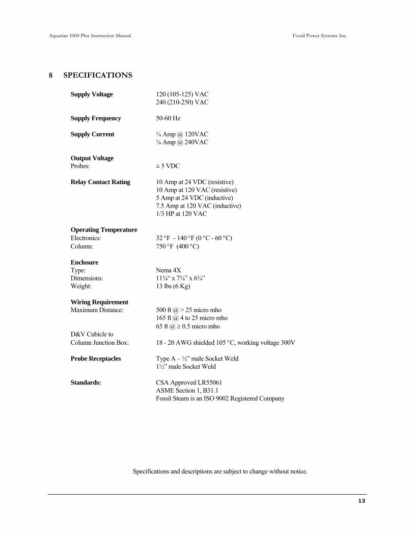
8 SPECIFICATIONS
Supply Voltage 120 (105-125) VAC 240 (210-250) VAC
Supply Frequency 50-60 Hz Supply Current ¼ Amp @ 120VAC
⅛ Amp @ 240VAC Output Voltage Probes: ± 5 VDC Relay Contact Rating 10 Amp at 24 VDC (resistive)
10 Amp at 120 VAC (resistive) 5 Amp at 24 VDC (inductive)
7.5 Amp at 120 VAC (inductive) 1/3 HP at 120 VAC
Operating Temperature Electronics: 32 °F - 140 °F (0 °C - 60 °C) Column: 750 °F (400 °C) Enclosure Type: Nema 4X Dimensions: 11¾“ x 7⅜” x 6¾” Weight: 13 lbs (6 Kg) Wiring Requirement Maximum Distance: 500 ft @ > 25 micro mho
165 ft @ 4 to 25 micro mho 65 ft @ ≥ 0.5 micro mho
D&V Cubicle to Column Junction Box: 18 - 20 AWG shielded 105 °C, working voltage 300V Probe Receptacles Type A – ½” male Socket Weld 1½” male Socket Weld Standards: CSA Approved LR55061 ASME Section 1, B31.1
Fossil Steam is an ISO 9002 Registered Company
Specifications and descriptions are subject to change without notice.

Aquarian 1000 Plus Instruction Manual Fossil Power Systems Inc.
14
9 AVAILABLE OPTIONS
Additional options can be purchased to customize the Aquarian 1000 Mini System to individual applications:
• Column mounted junction box, pre-wired to probes
• Dual power source relay • Adjustable trip/alarm time delay • Trip bypass pushbutton • Stainless steel column 2000 psig
750°F • Stainless steel column 3000 psig
750°F

Aquarian 1000 Plus Instruction Manual Fossil Power Systems Inc.
15
TE
CH
NO
LOG
IES
INC
.
FO
SS
ILS
TEA
M
Figure 4 - Aquarian 1000 Plus System Wiring
Aquarian 1000 Plus Instruction Manual Fossil Power Systems Inc.
16
TEC
HN
OLO
GIE
SS
TEA
M
INC
.
FO
SS
IL
Figure 5 - Face Plate Label
Aquarian 1000 Plus Instruction Manual Fossil Power Systems Inc.
17
R
ELAY
CO
NTA
CT
SHO
RT
CIR
CU
IT E
NAB
LE J
UM
PER
SEN
SITI
VITY
SO
CK
ETS
CO
NTI
NU
ITY
DIS
ABLE
TYPI
CAL
SH
UN
T SE
TUP
PRO
BE
OPE
N O
R S
HO
RT
CIR
CU
IT F
AULT
Figure 6 - Jumper Settings

Fossil Power Systems Inc.
10 Mosher Drive • Dartmouth, Nova Scotia • Canada B3B 1N5 Phone 902-468-4701 ext 720 • Fax 902-468-2323
email enquiries: [email protected] www.fossil.ca