electronic sxt - gmautoflow.co.uk · 5000 - 5600 - 4600 2510 - 2750 - 2850 2910 e n g l i s h....
TRANSCRIPT

ELECTRONIC SXT
ELECTRONIC SXT
1 - VALVE OPERATION
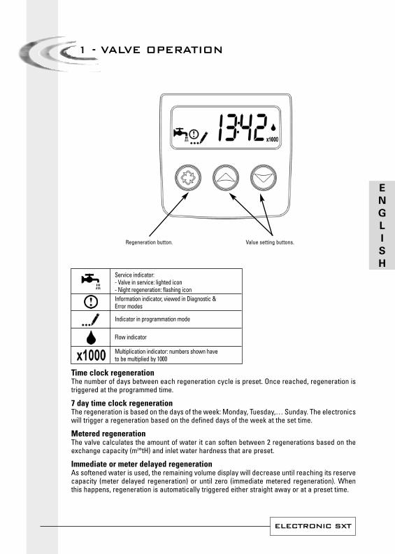
Regeneration button. Value setting buttons.
Time clock regenerationThe number of days between each regeneration cycle is preset. Once reached, regeneration istriggered at the programmed time.
7 day time clock regenerationThe regeneration is based on the days of the week: Monday, Tuesday,… Sunday. The electronicswill trigger a regeneration based on the defined days of the week at the set time.
Metered regenerationThe valve calculates the amount of water it can soften between 2 regenerations based on theexchange capacity (m3°tH) and inlet water hardness that are preset.
Immediate or meter delayed regenerationAs softened water is used, the remaining volume display will decrease until reaching its reservecapacity (meter delayed regeneration) or until zero (immediate metered regeneration). Whenthis happens, regeneration is automatically triggered either straight away or at a preset time.
Service indicator:- Valve in service: lighted icon- Night regeneration: flashing iconInformation indicator, viewed in Diagnostic &Error modes
Indicator in programmation mode
Flow indicator
Multiplication indicator: numbers shown haveto be multiplied by 1000
E
N
G
L
I
S
H
ELECTRONIC SXT
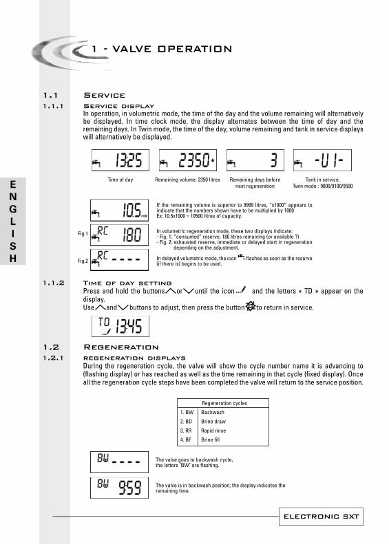
ServiceService displayIn operation, in volumetric mode, the time of the day and the volume remaining will alternativelybe displayed. In time clock mode, the display alternates between the time of day and theremaining days. In Twin mode, the time of the day, volume remaining and tank in service displayswill alternatively be displayed.
Time of day Remaining volume: 2350 litres Remaining days before Tank in service, next regeneration Twin mode : 9000/9100/9500
Time of day settingPress and hold the buttons or until the icon and the letters « TD » appear on thedisplay.Use and buttons to adjust, then press the button to return in service.
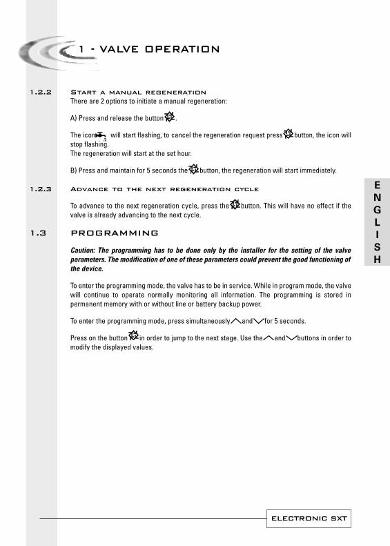
Regenerationregeneration displaysDuring the regeneration cycle, the valve will show the cycle number name it is advancing to(flashing display) or has reached as well as the time remaining in that cycle (fixed display). Onceall the regeneration cycle steps have been completed the valve will return to the service position.
The valve is in backwash position; the display indicates theremaining time.
The valve goes to backwash cycle,the letters "BW" are flashing.
Regeneration cycles
1. BW Backwash
2. BD Brine draw
3. RR Rapid rinse
4. BF Brine fill
If the remaining volume is superior to 9999 litres, “x1000” appears toindicate that the numbers shown have to be multiplied by 1000Ex: 10.5x1000 = 10500 litres of capacity.
1 - VALVE OPERATION
In volumetric regeneration mode, these two displays indicate:- Fig. 1: “consumed” reserve, 180 litres remaining (or available ?)- Fig. 2: exhausted reserve, immediate or delayed start in regeneration
depending on the adjustment.
In delayed volumetric mode, the icon flashes as soon as the reserve(if there is) begins to be used.
Fig.1
Fig.2
1.11.1.1
1.1.2
1.21.2.1
E
N
G
L
I
S
H
ELECTRONIC SXT
Start a manual regenerationThere are 2 options to initiate a manual regeneration:
A) Press and release the button .
The icon will start flashing, to cancel the regeneration request press button, the icon willstop flashing.The regeneration will start at the set hour.
B) Press and maintain for 5 seconds the button, the regeneration will start immediately.
Advance to the next regeneration cycle
To advance to the next regeneration cycle, press the button. This will have no effect if thevalve is already advancing to the next cycle.
PROGRAMMING
Caution: The programming has to be done only by the installer for the setting of the valveparameters. The modification of one of these parameters could prevent the good functioning ofthe device.
To enter the programming mode, the valve has to be in service. While in program mode, the valvewill continue to operate normally monitoring all information. The programming is stored inpermanent memory with or without line or battery backup power.
To enter the programming mode, press simultaneously and for 5 seconds.
Press on the button in order to jump to the next stage. Use the and buttons in order tomodify the displayed values.
1 - VALVE OPERATION
1.2.2
1.2.3
1.3
E
N
G
L
I
S
H
ELECTRONIC SXT
1 - VALVE OPERATION
Note: You must pass through all the programming steps and come back in service position tosave the modifications that have been done during the programming mode.
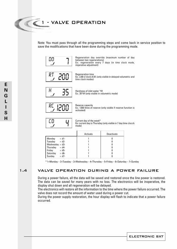
* 1=Monday – 2=Tuesday – 3=Wednesday – 4=Thursday – 5=Friday – 6=Saturday – 7=Sunday
VALVE OPERATION DURING A POWER FAILURE
During a power failure, all the data will be saved and restored once the line power is restored.The data can be saved for many years with no loss. The electronics will be inoperative, thedisplay shut down and all regeneration will be delayed.The electronics will restore all the information to the time where the power failure occurred. Thevalve does not record the amount of water used during a power cut.During the power supply restoration, the hour display will flash to indicate that a power failureoccurred.
Current day of the week*Ex: current day is Thursday (only visible in 7 day time clocckmode)
Reserve capacityEx.: 1200 litres of reserve (only visible if reserve function isactivated)
Hardness of inlet water °tHEx.: 35°tH (only visible in volumetric mode)
Regeneration timeEx.: 2.00 o’clock A.M. (only visible in delayed volumetric andtime clock modes)
Regeneration day override (maximum number of daybetween two regenerations)Ex.: regeneration every 7 days (in time clock mode,imperative adjustment)
Activate Deactivate
Monday = d1- 1 0Tuesday = d2- 1 0Wednesday = d3- 1 0Thursday = d4- 1 0Friday = d5- 1 0Saturday = d6- 1 0Sunday = d7- 1 0
1.4
E
N
G
L
I
S
H
ELECTRONIC SXT
2 - PROGRAMMING
1. Press once the buttonto go from one displaymode to another.
2. Set parameters values byusing the andbuttons.
3. Depending on theprogrammation, somedisplays will not appearand some will not bevariable.
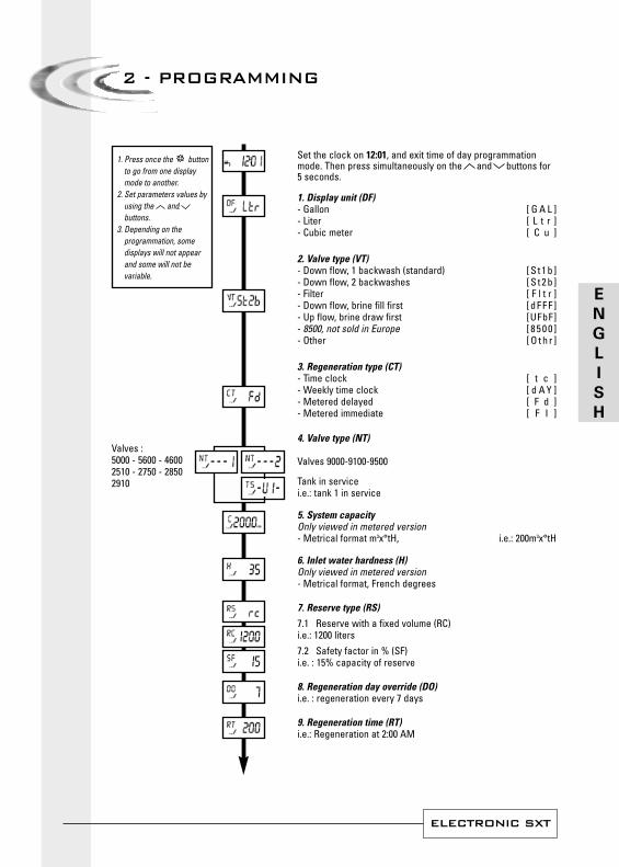
Set the clock on 12:01, and exit time of day programmationmode. Then press simultaneously on the and buttons for5 seconds.
1. Display unit (DF)- Gallon [ G A L ]- Liter [ L t r ]- Cubic meter [ C u ]
2. Valve type (VT)- Down flow, 1 backwash (standard) [ S t 1 b ]- Down flow, 2 backwashes [ S t 2 b ]- Filter [ F l t r ]- Down flow, brine fill first [ d F F F ]- Up flow, brine draw first [UFbF]- 8500, not sold in Europe [ 8 5 0 0 ]- Other [ O t h r ]
3. Regeneration type (CT)- Time clock [ t c ]- Weekly time clock [ d A Y ]- Metered delayed [ F d ]- Metered immediate [ F I ]
4. Valve type (NT)
Valves 9000-9100-9500
Tank in servicei.e.: tank 1 in service
5. System capacityOnly viewed in metered version- Metrical format m3x°tH, i.e.: 200m3x°tH
6. Inlet water hardness (H)Only viewed in metered version - Metrical format, French degrees
7. Reserve type (RS)
7.1 Reserve with a fixed volume (RC)i.e.: 1200 liters7.2 Safety factor in % (SF)i.e. : 15% capacity of reserve
8. Regeneration day override (DO)i.e. : regeneration every 7 days
9. Regeneration time (RT)i.e.: Regeneration at 2:00 AM
Valves :5000 - 5600 - 46002510 - 2750 - 28502910
E
N
G
L
I
S
H
ELECTRONIC SXT
2 - PROGRAMMING
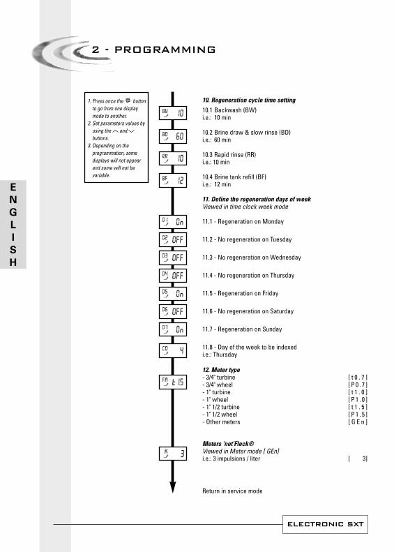
10. Regeneration cycle time setting
10.1 Backwash (BW)i.e.: 10 min
10.2 Brine draw & slow rinse (BD)i.e.: 60 min
10.3 Rapid rinse (RR)i.e.: 10 min
10.4 Brine tank refill (BF)i.e.: 12 min
11. Define the regeneration days of weekViewed in time clock week mode
11.1 - Regeneration on Monday
11.2 - No regeneration on Tuesday
11.3 - No regeneration on Wednesday
11.4 - No regeneration on Thursday
11.5 - Regeneration on Friday
11.6 - No regeneration on Saturday
11.7 - Regeneration on Sunday
11.8 - Day of the week to be indexed i.e.: Thursday
12. Meter type- 3/4" turbine [ t 0 . 7 ]- 3/4" wheel [ P 0 . 7 ]- 1" turbine [ t 1 . 0 ]- 1" wheel [ P 1 . 0 ]- 1" 1/2 turbine [ t 1 . 5 ]- 1" 1/2 wheel [ P 1 . 5 ]- Other meters [ G E n ]
Meters ‘not’Fleck®Viewed in Meter mode [ GEn]i.e.: 3 impulsions / liter [ 3]
1. Press once the buttonto go from one displaymode to another.
2. Set parameters values byusing the andbuttons.
3. Depending on theprogrammation, somedisplays will not appearand some will not bevariable.
Return in service mode
E
N
G
L
I
S
H
ELECTRONIC SXT
2 - PROGRAMMING
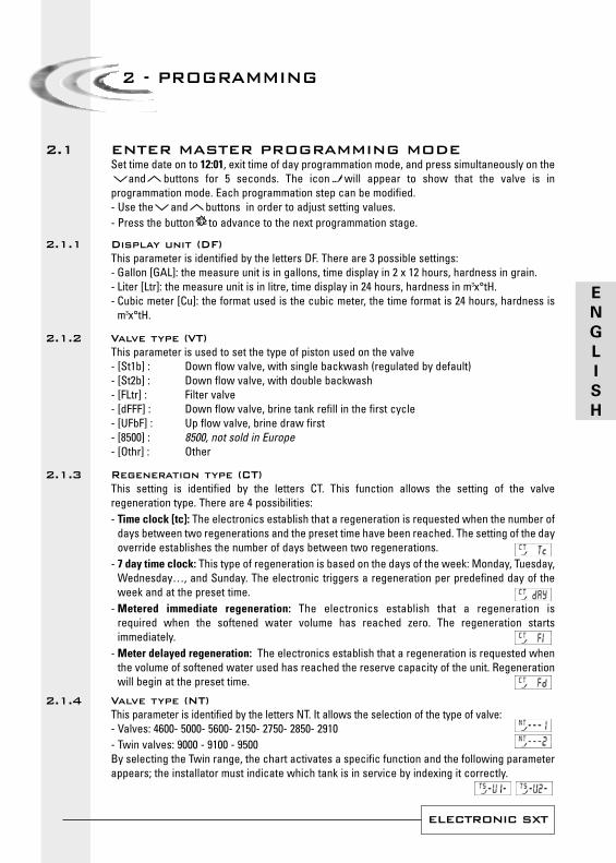
ENTER MASTER PROGRAMMING MODESet time date on to 12:01, exit time of day programmation mode, and press simultaneously on the
and buttons for 5 seconds. The icon will appear to show that the valve is inprogrammation mode. Each programmation step can be modified.- Use the and buttons in order to adjust setting values.- Press the button to advance to the next programmation stage.
Display unit (DF)This parameter is identified by the letters DF. There are 3 possible settings:- Gallon [GAL]: the measure unit is in gallons, time display in 2 x 12 hours, hardness in grain.- Liter [Ltr]: the measure unit is in litre, time display in 24 hours, hardness in m3x°tH.- Cubic meter [Cu]: the format used is the cubic meter, the time format is 24 hours, hardness is
m3x°tH.
Valve type (VT)This parameter is used to set the type of piston used on the valve- [St1b] : Down flow valve, with single backwash (regulated by default)- [St2b] : Down flow valve, with double backwash- [FLtr] : Filter valve- [dFFF] : Down flow valve, brine tank refill in the first cycle- [UFbF] : Up flow valve, brine draw first - [8500] : 8500, not sold in Europe- [Othr] : Other
Regeneration type (CT)This setting is identified by the letters CT. This function allows the setting of the valveregeneration type. There are 4 possibilities:- Time clock [tc]: The electronics establish that a regeneration is requested when the number of
days between two regenerations and the preset time have been reached. The setting of the dayoverride establishes the number of days between two regenerations.
- 7 day time clock: This type of regeneration is based on the days of the week: Monday, Tuesday,Wednesday…, and Sunday. The electronic triggers a regeneration per predefined day of theweek and at the preset time.
- Metered immediate regeneration: The electronics establish that a regeneration is required when the softened water volume has reached zero. The regeneration startsimmediately.
- Meter delayed regeneration: The electronics establish that a regeneration is requested whenthe volume of softened water used has reached the reserve capacity of the unit. Regenerationwill begin at the preset time.
Valve type (NT)This parameter is identified by the letters NT. It allows the selection of the type of valve:- Valves: 4600- 5000- 5600- 2150- 2750- 2850- 2910- Twin valves: 9000 - 9100 - 9500 By selecting the Twin range, the chart activates a specific function and the following parameterappears; the installator must indicate which tank is in service by indexing it correctly.
2.1
2.1.1
2.1.2
2.1.3
2.1.4
E
N
G
L
I
S
H
ELECTRONIC SXT
2 - PROGRAMMING
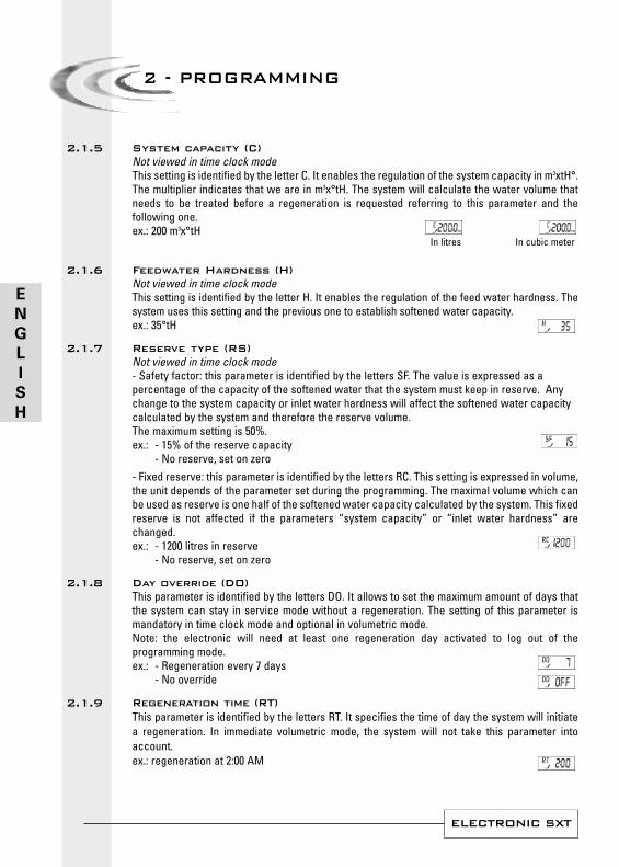
System capacity (C)Not viewed in time clock modeThis setting is identified by the letter C. It enables the regulation of the system capacity in m3xtH°.The multiplier indicates that we are in m3x°tH. The system will calculate the water volume thatneeds to be treated before a regeneration is requested referring to this parameter and thefollowing one.ex.: 200 m3x°tH
Feedwater Hardness (H)Not viewed in time clock modeThis setting is identified by the letter H. It enables the regulation of the feed water hardness. Thesystem uses this setting and the previous one to establish softened water capacity.ex.: 35°tH
Reserve type (RS)Not viewed in time clock mode - Safety factor: this parameter is identified by the letters SF. The value is expressed as apercentage of the capacity of the softened water that the system must keep in reserve. Anychange to the system capacity or inlet water hardness will affect the softened water capacitycalculated by the system and therefore the reserve volume. The maximum setting is 50%.ex.: - 15% of the reserve capacity
- No reserve, set on zero- Fixed reserve: this parameter is identified by the letters RC. This setting is expressed in volume,the unit depends of the parameter set during the programming. The maximal volume which canbe used as reserve is one half of the softened water capacity calculated by the system. This fixedreserve is not affected if the parameters “system capacity” or “inlet water hardness” arechanged.ex.: - 1200 litres in reserve
- No reserve, set on zero
Day override (DO)This parameter is identified by the letters DO. It allows to set the maximum amount of days thatthe system can stay in service mode without a regeneration. The setting of this parameter ismandatory in time clock mode and optional in volumetric mode.Note: the electronic will need at least one regeneration day activated to log out of theprogramming mode. ex.: - Regeneration every 7 days
- No override
Regeneration time (RT)This parameter is identified by the letters RT. It specifies the time of day the system will initiatea regeneration. In immediate volumetric mode, the system will not take this parameter intoaccount.ex.: regeneration at 2:00 AM
In cubic meterIn litres
2.1.5
2.1.6
2.1.7
2.1.8
2.1.9
E
N
G
L
I
S
H
ELECTRONIC SXT
2 - PROGRAMMING
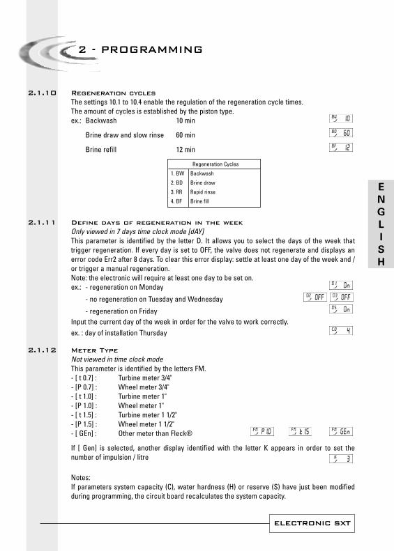
Regeneration cyclesThe settings 10.1 to 10.4 enable the regulation of the regeneration cycle times.The amount of cycles is established by the piston type.ex.: Backwash 10 min
Brine draw and slow rinse 60 min
Brine refill 12 min
Define days of regeneration in the weekOnly viewed in 7 days time clock mode [dAY]This parameter is identified by the letter D. It allows you to select the days of the week thattrigger regeneration. If every day is set to OFF, the valve does not regenerate and displays anerror code Err2 after 8 days. To clear this error display: settle at least one day of the week and /or trigger a manual regeneration.Note: the electronic will require at least one day to be set on.ex.: - regeneration on Monday
- no regeneration on Tuesday and Wednesday
- regeneration on FridayInput the current day of the week in order for the valve to work correctly.ex. : day of installation Thursday
Meter TypeNot viewed in time clock modeThis parameter is identified by the letters FM.- [ t 0.7] : Turbine meter 3/4" - [P 0.7] : Wheel meter 3/4" - [ t 1.0] : Turbine meter 1"- [P 1.0] : Wheel meter 1"- [ t 1.5] : Turbine meter 1 1/2"- [P 1.5] : Wheel meter 1 1/2"- [ GEn] : Other meter than Fleck®
If [ Gen] is selected, another display identified with the letter K appears in order to set thenumber of impulsion / litre
Notes:If parameters system capacity (C), water hardness (H) or reserve (S) have just been modifiedduring programming, the circuit board recalculates the system capacity.
Regeneration Cycles
1. BW Backwash
2. BD Brine draw
3. RR Rapid rinse
4. BF Brine fill
2.1.10
2.1.11
2.1.12
E
N
G
L
I
S
H
ELECTRONIC SXT
2 - PROGRAMMING
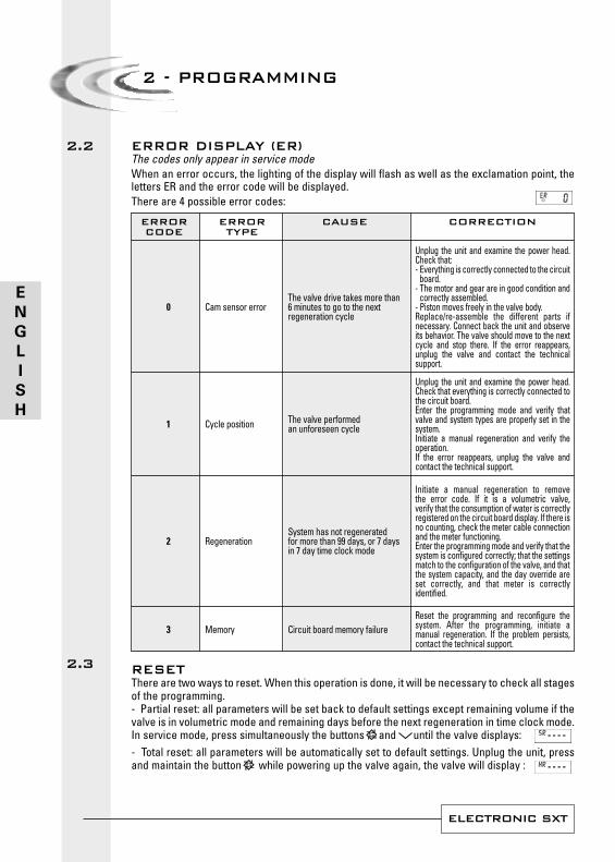
ERROR DISPLAY (ER)The codes only appear in service modeWhen an error occurs, the lighting of the display will flash as well as the exclamation point, theletters ER and the error code will be displayed.There are 4 possible error codes:
RESETThere are two ways to reset. When this operation is done, it will be necessary to check all stagesof the programming.- Partial reset: all parameters will be set back to default settings except remaining volume if thevalve is in volumetric mode and remaining days before the next regeneration in time clock mode. In service mode, press simultaneously the buttons and until the valve displays:- Total reset: all parameters will be automatically set to default settings. Unplug the unit, pressand maintain the button while powering up the valve again, the valve will display :
2.2
ERROR ERROR CAUSE CORRECTIONCODE TYPE
The valve drive takes more than6 minutes to go to the nextregeneration cycle
The valve performedan unforeseen cycle
System has not regeneratedfor more than 99 days, or 7 daysin 7 day time clock mode
Circuit board memory failure
0
1
2
3
Cam sensor error
Cycle position
Regeneration
Memory
Unplug the unit and examine the power head.Check that:- Everything is correctly connected to the circuit
board.- The motor and gear are in good condition and
correctly assembled.- Piston moves freely in the valve body.Replace/re-assemble the different parts ifnecessary. Connect back the unit and observeits behavior. The valve should move to the nextcycle and stop there. If the error reappears,unplug the valve and contact the technicalsupport.
Unplug the unit and examine the power head.Check that everything is correctly connected tothe circuit board.Enter the programming mode and verify thatvalve and system types are properly set in thesystem.Initiate a manual regeneration and verify theoperation.If the error reappears, unplug the valve andcontact the technical support.
Initiate a manual regeneration to removethe error code. If it is a volumetric valve,verify that the consumption of water is correctlyregistered on the circuit board display. If there isno counting, check the meter cable connectionand the meter functioning.Enter the programming mode and verify that thesystem is configured correctly; that the settingsmatch to the configuration of the valve, and thatthe system capacity, and the day override areset correctly, and that meter is correctlyidentified.
Reset the programming and reconfigure thesystem. After the programming, initiate amanual regeneration. If the problem persists,contact the technical support.
2.3
E
N
G
L
I
S
H
ELECTRONIC SXT
3 - DIAGNOSTIC MODE
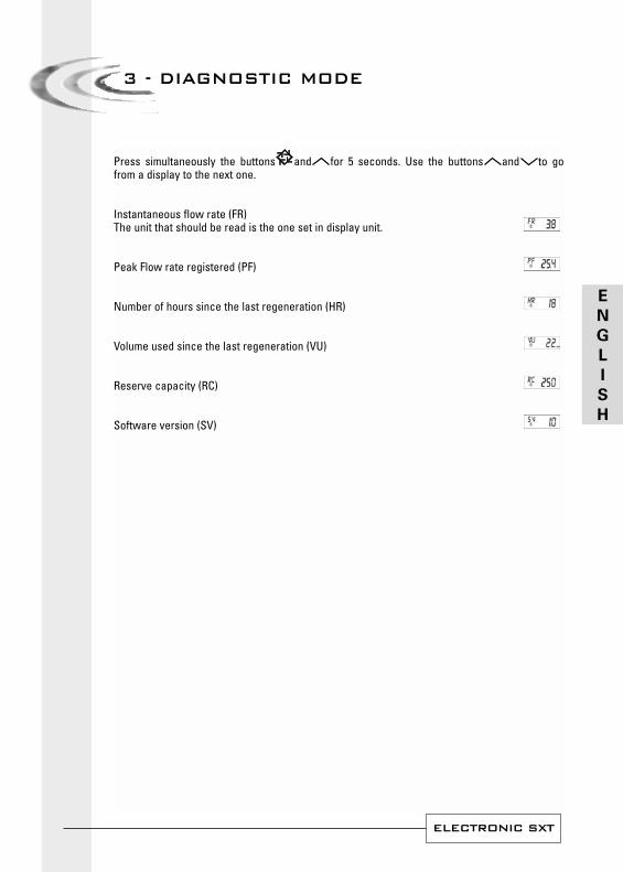
Press simultaneously the buttons and for 5 seconds. Use the buttons and to gofrom a display to the next one.
Instantaneous flow rate (FR)The unit that should be read is the one set in display unit.
Peak Flow rate registered (PF)
Number of hours since the last regeneration (HR)
Volume used since the last regeneration (VU)
Reserve capacity (RC)
Software version (SV)
E
N
G
L
I
S
H