electronic servicing - american radio history: documents...
TRANSCRIPT
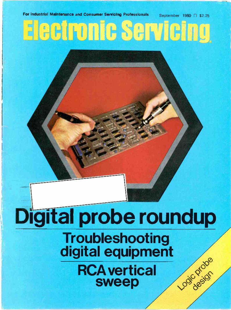
For Industrial Maintenance and Consumer Servicing Professionals September 1980 $2.25
Digital probe roundupTroubleshootingdigital equipment
RCA verticalsweep
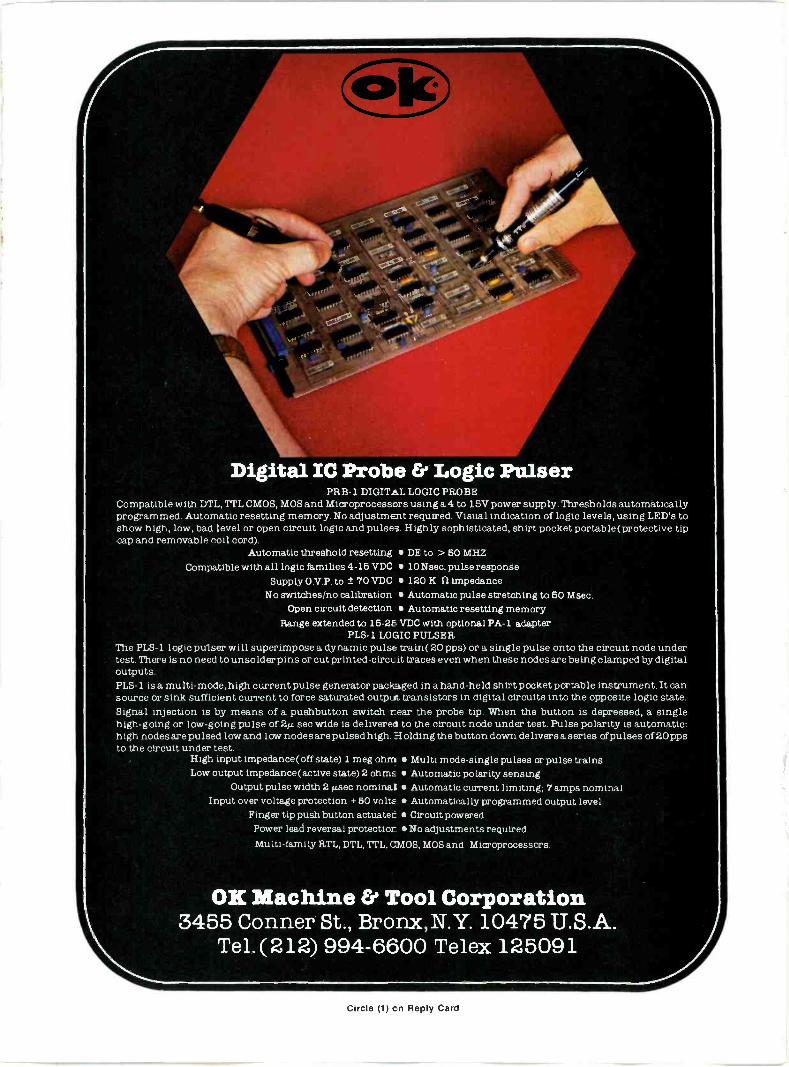
Digital IC Probe & Logic PulserPRB-1 DIGITAL LOGIC PROBE
Compatible with DTL, TTL CMOS, MOS and Microprocessors using a 4 to 15V power supply. Thresholds automaticallyprogrammed. Automatic resetting memory. No adjustment required. Visual indication of logic levels, using LED's toshow high, low, bad level or open circuit logic and pulses. Highly sophisticated, shirt pocket portable( protective tipcap and removable coil cord).
Automatic threshold resetting DE to > 50 MHZCompatible with all logic families 4-15 VDC 10 Nsec pulse response
Supply 0 V P to ± 70 VDC 120 K 11 impedanceNo switches/no calibration Automatic pulse stretching to 50 Msec.
Open circuit detection Automatic resetting memoryRange extended to 15-2E. VDC with optional PA -1 adapter
PLS-1 LOGIC PIILSERThe PLS-1 logic pulser will superimpose a dynamic pulse train( 20 pps) or a single pulse onto the circuit node undertest. There is no need to unsolder pins or cutprinted-circuit traces even when these nodes are being clamped by digitaloutputs.PLS-1 is a multi -mode, high current pulse generator packaged in a hand-held shirt pocket portable instrument. It cansource or sink sufficient current to force saturated output transistors in digital circuits into the opposite logic state.Signal injection is by means of a pushbutton switch rear the probe tip. When the button is depressed, a singlehigh -going or low -going pulse of 2A sec wide is delivered to the circuit node under test. Pulse polarity is automatic:high nodes are pulsed low and low nodes are pulsed high. Holding the button down delivers a series of pulses of 20 ppsto the circuit under test.
High input impedance( off state) 1 meg ohm Multi mode -single pulses or pulse trainsLow output impedance( active state) 2 ohms Automatic polarity sensing
Output pulse width 2 µsec nominal Automatic current limiting; 7 amps nominalInput over voltage protection +50 volts Automatically programmed output level
Finger tip push button actuated Circuit poweredPower lead reversal protection No adjustments requiredMulti -family RTL, DTL, TTL, CMOS, MOS and Microprocessors.
OK Machine & Tool Corporation3455 Conner St., Bronx,N.Y. 10475 U.S.A.
Tel. (212) 994-6600 Telex 125091
Circle (1) on Reply Card
Electronic ServicingEditorial, advertising and circulation corre-spondence should be addressed to P.O.Box 12901, Overland Park, KS 66212 (a
suburb of Kansas City, MO); (913) 888-4664.
EDITORIALBill Rhodes, Editorial DirectorCarl Babcoke, Consumer Servicing
ConsultantKevin Kious, Managing EditorMary Thornbrugh, Associate Editor
ARTDudley Rose, Art DirectorLinda S. Franzblau, Graphic Designer
CIRCULATIONJohn C. Arnst, DirectorEvelyn Rogers, Manager
ADMINISTRATIONR. J. Hancock, PresidentGeorge Laughead, Publisher
ADVERTISINGGreg Garrison, National Sales ManagerDee Unger, Production
Regional advertising sales offices listednear Advertiser's Index.
Member.ABP American Business Press
Member,Audit Bureauof Circulation
ELECTRONIC SERVICING (USPS 462-050)(with which is combined PF Reporter) Ispublished monthly by Intertec PublishingCorp., 9221 Ouiyira Road, Overland Park,KS 66212. Controlled Circulation Postagepaid at Shawnee Mission, KS 66201. SendForm 3579 to P.O. Box 12901, OverlandPark, KS 66212.
ELECTRONIC SERVICING is edited fortechnicians who repair home -entertainmentelectronic equipment (such as TV, radio,tape, stereo and record players) and forindustrial technicians who repair defectiveproduction -line merchandise, test equip-ment, or industrial controls in factories.
Subscription prices to qualified sub-scribers: 1 year-$12, 2 years-$19, 3years-$24, in the USA and Its posses-slones. All other foreign Countries: 1
year-$15, 2 years-$25. Subscriptionprices to all others: 1 year-$25, 2years-$50, in the USA and Its posses-sions. All other fcreign countries: 1
year-$34, 2 years-$68. Single copy price$2.25; back copies $3.00. Adjustmentnecessitated by subscription termination tosingle copy rate. Allow 6 to 8 weeksdelivery for change of address. Allow 6 to 8weeks for new subscriptions.
INTERTEC PUBLISHING CORP.C 1980. All rights reserved.
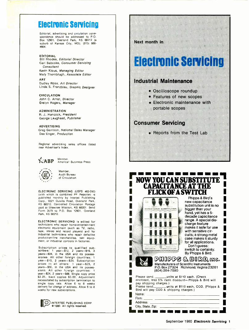
Next month in
Electronic servicing
Industrial Maintenance
Oscilloscope roundup Features of new scopes Electronic maintenance with
portable scopes
Consumer Servicing
Reports from the Test Lab
CAPACITANCE AT THEFLICK OFA SWITCH
VACITANCE
Phipps & Bird'snew capacitancesubstitution unit is nobigger than yourhand, yet has a 5 -decade capacitancerange. A special dis-charge featuremakes it safe for usewith sensitive cir-cuits; a strong metalcase makes it sturdyfor all applications.
Don't guess:switch to certainty.By Phipps & Bird.
pU7 0 P[?@ G1D, ocnoManufacturers of Scientific InstrumentsP.O. Box 27324 Richmond, Virginia 23261(804) 264-7590
Please send units at $110 each. (Checkenclosed, less 5% cash discount-Phipps & Bird willpay shipping charges.)Please send units at $110 each, COD. (Phipps &Bird will pay COD & shipping charges.)Name:Firm:Address:City, State, Zip'
NM MIN Ell Ell Ell Mill 11111
September 1980 Electronic Servicing 1
For industrial maintenance and consumer servicing professicnals
September, 1980 ElVolume 30, No. 9 Electronic Servicing.
IndustrialMRO
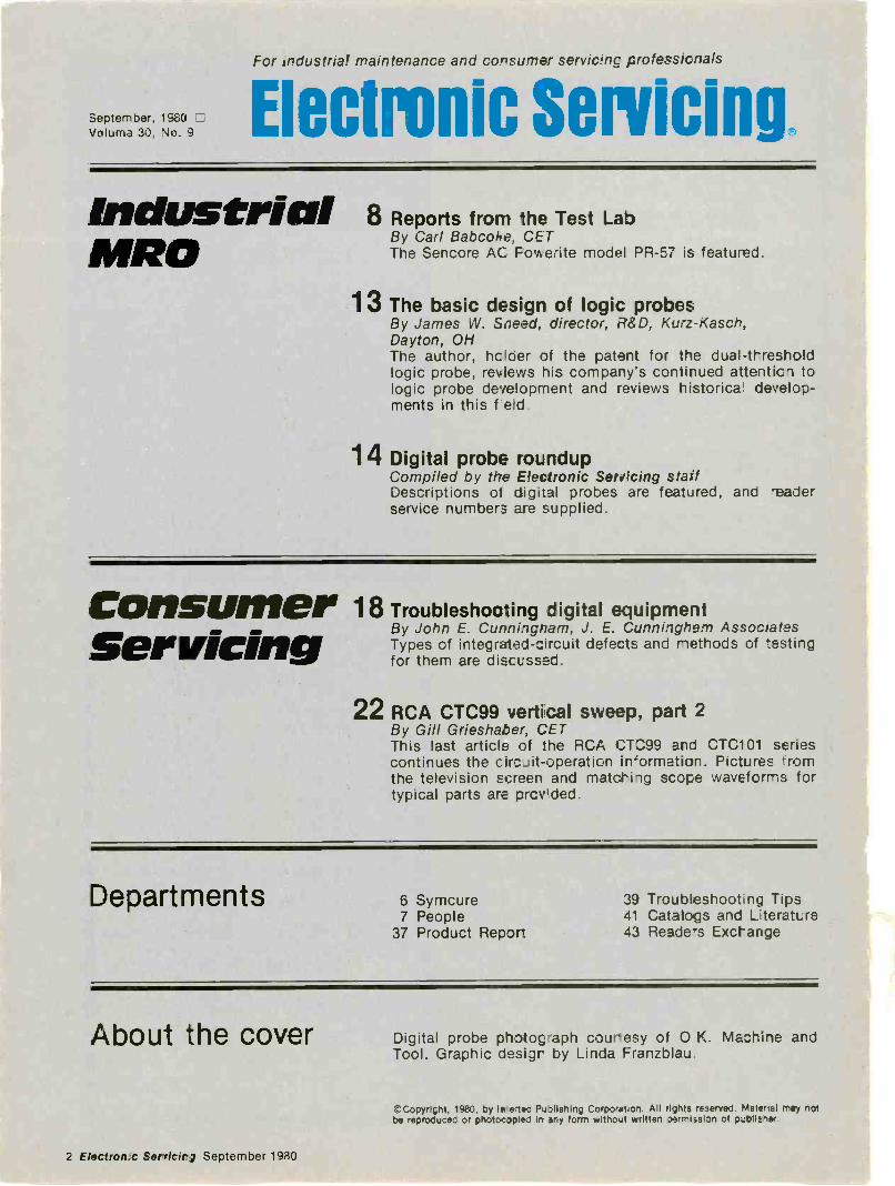
8 Reports from the Test LabBy Carl Babcoke, CETThe Sencore AC Fowerite model PR -57 is featured.
13 The basic design of logic probesBy James W. Sneed, director, R&D, Kurz-Kasch,Dayton, OHThe author, hclder of the patent for the dual -thresholdlogic probe, reviews his company's continued attenticn tologic probe development and reviews historical develop-ments in this f
14 Digital probe roundupCompiled by the Electronic Servicing staffDescriptions of digital probes are featured, and readerservice numbers are supplied.
Consumer 18_ _ Troubleshooting digital equipmentBy John E. Cunningham, J. E. Cunningham AssociatesServicingTypes of integrated -circuit defects and methods of testingfor them are discussed.
22 RCA CTC99 vertical sweep, part 2By Gill Grieshaber, CETThis last article of the RCA CTC99 and CTC101 seriescontinues the circuit -operation in'ormation. Pictures fromthe television screen and matching scope waveforms fortypical parts ars prcvlded.
Departments 6 Symcure7 People
37 Product Repor
39 Troubleshootng Tips41 Catalogs and Lterature43 Readers Exchange
About the cover Digital probe photograph courtesy of 0 K. Machine andTool. Graphic desigr by Lirda Franzblau.
2 Electron c Servicirg September 1980
©Copyright, 1980, by ivertec PuOlishing Corporet,on. All rights reserved. Materiel may notbe reproduced or photocopied in any form without written permission of p4blither
CASH IN ON SAMS FREE BOOK OFFER!With your order of $20 or more, you can select a FREE BONUS BOOK ...value up to $5.95. Take advantage ofthis money -saving, limited time offer on Sams Special Projects Books. Build your $20 order from the current,popular titles listed below. Free Bonus Book selections are indicated by an asterisk (*). Mix or match the booksyou want ...then indicate your free book selection on the order form.
AUDIOri TAPE RECORDING FOR THE1-1 HOBBYIST -4th Edition.
Cassettes, eight -track, open reel, andhome video tape. Covers tapingbroadcasts, live sound, special effectsand editing. #21348. $4.95
1-1 STEREO HIGH-FIDELITY SPEAKERSYSTEMS.Covers a broad range of stereo speakersystems. Includes shopping tips forequipment best suited to your needs.#21514. $5.95.
ri LISTEN TO RADIO ENERGY, LIGHT, ANDI-I SOUND.
Hear fascinating, exciting new soundsthrough inexpensive amplifiers. #21525.$5.95. BONUS BOOK SELECTION.
ELECTRONICS
1-1 LED CIRCUITS AND PROJECTS.Covers all kinds of LED applications --from digital display and logic testerprobes to communications systems andtravel aids for the blind. #21006. $5.25.
1-1 ELECTRONIC CIRCUITBOOK 1:I-I PROJECT CONSTRUCTION.
Covers various kinds of electronic circuits and projects that can be madewith them. #21241. $3.25. BONUS BOOKSELECTION.
n INTRODUCTION TO RADIO" ASTRONOMY.
Explains how to construct several low-cost radio telescopes that are suitablefor observation of solar phenomena,galactic noise and Intergalactic signalsources. #21246. $4.50. BONUS BOOKSELECTION.
1-1 ELECTRONIC CIRCUITBOOK 5:" LED PROJECTS.
Instructions for making four -layer diodepulser, avalanche transistor pulser,high -circuit LED pulser, amplitude -modulation voice transmitter and re-ceiver, and solid-state oscilloscope.#21311. $3.75. BONUS BOOK SELECTION.
El BUILD -IT BOOK OF SAFETYELECTRONICS.Contains ideas for building severalnovel projects to protect your home,family, and car. #21334. $3.50.
ni BUILD -IT BOOK OF HOMEELECTRONICS.Put solid-state devices and ICs to work inyour home. Includes 13 interesting proj-ects you can build. #21409. $3.50.
ri BUILDING AND INSTALLING" ELECTRONIC INTRUSION ALARMS.
Written for the novice who wants to in-stall a security system in his home...andthe technician who wants to enter thelucrative field of security electronics#21465. $4.95.
ri UNIQUE ELECTRONIC WEATHERL --J PROJECTS.
You can build projects to measure tem-perature, wind speed, and direction,barometric pressure and construct athermostat "with a brain" to help con-serve energy. #21484. $7.95.
ri PRACTICAL LOW-COST ICI-I PROJECTS -2nd Edition.
Presents complete parts lists andschematic diagrams for 38 different,easy, low-cost Integrated circuit proj-ects. #21599. $4.50.
1-1 INTEGRATED CIRCUIT PROJECTS-2nd1-1 Edition.IC projects that are useful, fun to build,and educational. All projects havebeen tested and debugged. #21616.$5.50.
ri ELECTRONIC TELEPHONE PROJECTS.15 projects that can extend thecapabilities of your present telephone.#21618. $6.50.
r-1 99 PRACTICAL ELECTRONICI ---I PROJECTS -2nd Edition.
Choose from audio amplifiers, testequipment, photography projects, orautomobile devices. Many can be builtfor less than $10. #21635. $4.95.
1-1 SIMPLE IC TEST INSTRUMENTSI-I YOU CAN BUILD.
31 practical instruments and test acces-sory circuits you can inexpensively andeasily build from scratch. #21683. $4.95.
El ONE EVENING ELECTRONICL---1 PROJECTS.
Even beginners can build electronicprojects with this book, Simple tools andreadily available components can re-sult in an evening of fun and useful proj-ects for the house, garage, workshop, oroffice. #21699. $5.95.
COMPUTERS
71 GETTING ACQUAINTED WITHL-1 MICROCOMPUTERS.
Written especially for engineers, techni-cians, scientists, and others who need toknow about microcomputers. Self -instructional. #21486. $8.95.
ri GUIDEBOOK TO SMALL COMPUTERS.I --I A must for anyone thinking about buying
a small computer. Introduces smallcomputers, software, and hardware.Surveys 21 currently popular systems. In-cludes a directory of small computermanufacturers. #21698. $4.95.
ENGINES
1-1 UNDERSTANDING YOUR CAR.Not a fix -It -yourself guidel Instead, thisbook explains problems so that theycan be described to a mechanic.#21623. $8.95.
n DIESEL ENGINE MAINTENANCE.Explains proper maintenance proce-dures for the popular, new dieselengines. #21620 $6.95.
ENERGY
ri ENERGY SAVING HOME-1 IMPROVEMENTS.
Outlines conservation projects, Includ-ing furnace efficiency, Insulation, andsolar collectors. #21605. $7.95.ri SOLAR HEATING.Sound facts about heat transfer andheat retention. Includes examples ofuse and many Illustrations. #21621. $6.95
SamsBOOKS
SAVE 10% ON THESEBRAND NEW TITLES!
1-1 AUTOMOTIVE TUNE-UP ANDI-I EMISSION CONTROL
A do -It -yourself guide for many servicingand adjustment procedures which canbe performed by the average person.#21712. SAVE 10% ... ONLY $8.95.
1-1 ELECTRONICS FOR THE BEGINNER.No previous electronics knowledge isneeded to build exciting projects likecrystal sets, transistor radios, IC amplifier,CB and aircraft tuners, hi -fl am tuner,shortwave receiver, and many more. 100Illustrations and step-by-step Instructionsmake It fun and simple. #21737. SAVE 10%... ONLY $6.25.
ri YOU AND YOUR TELEPHONE.The complete telephone book. With thisbook, you can determine the best tele-phone system, accessories, and servicesfor your needs ... and determine whetheryou should buy and Install your ownequipment, or rent it from your localphone company #21744. SAVE 10%ONLY $4.45.
ri 101 WAYS TO USE YOUR VOM, NM,1--1 AND DVM-3rd Edition.
Gives both common and uncommonuses of the volt -ohm -meter and vacuum -tube voltmeter. Covers equipmentchecks, ac and dc voltage tests, de cur-rent tests, ohmmeter tests, signal -tracingtests, alignment applications, and color tvtests. Includes numerous Illustrations anddiagrams. #21756. SAVE 10% ... ONLY $5.95.
ORDER FORMHOWARD W. SAMS & CO., INC.
4300 West 62nd Street, P.O. Box 7092Indianapolis, Indiana 46206
(317) 298-5400
Indicate quantity In boxes above and completeorder Information below Return entire ad with order.
Sub Total
Add local sales tax (where applicable)
TOTAL AMOUNT
My total exceeds $201 Please send me my FREE BOOK
FREE BOOK Selection:
Title
CI PAYMENT ENCLOSED(save postage and handling costs)
0 CHECK 0 MONEY ORDER0 MASTER CHARGE VISA ADO27
interbank No. (Master Charge)
Account Number
Expiration DateMinimum Credit Card Purchase $10.
Name (print)
Signature
Address
City State Zip
Prices subject to change without notice.Offer expires 12/31/80
September 1980 Electronic Servicing 3
milmEyTBigscannernews of the industry
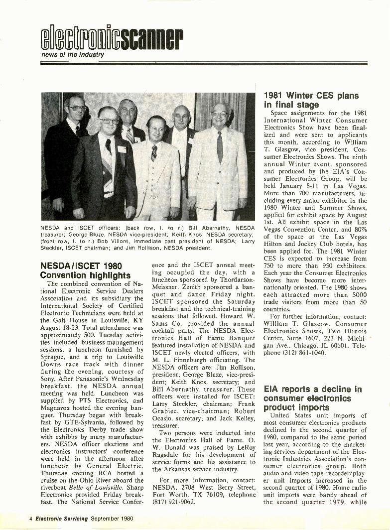
NESDA and ISCET officers: (back row, I. to r.) Bill Abernathy, NESDAtreasurer; George Bluze, NESDA vice-president; Keith Knos, NESDA secretary;(front row, I. to r.) Bob Villont, immediate past president of NESDA; LarrySteckler, ISCET chairman; and Jim Rollison, NESDA president.
NESDA/ISCET 1980Convention highlights
The combined convention of Na-tional Electronic Service DealersAssociation and its subsidiary theInternational Society of CertifiedElectronic Technicians were held atthe Galt House in Louisville, KYAugust 18-23. Total attendance wasapproximately 500. Tuesday activi-ties included business -managementsessions, a luncheon furnished bySprague, and a trip to LouisvilleDowns race track with dinnerduring the evening, courtesy ofSony. After Panasonic's Wednesdaybreakfast, the NESDA annualmeeting was held. Luncheon wassupplied by PTS Electronics, andMagnavox hosted the evening ban-quet. Thursday began with break-fast by GTE -Sylvania, followed bythe Electronics Derby trade showwith exhibits by many manufactur-ers. NESDA officer elections andelectronics instructors' conferencewere held in the afternoon afterluncheon by General Electric.Thursday evening RCA hosted acruise on the Ohio River aboard theriverboat Belle of Louisville. SharpElectronics provided Friday break-fast. The National Service Confer-
ence and the ISCET annual meet-ing occupied the day, with aluncheon sponsored by Thordarson-Meissner. Zenith sponsored a ban-quet and dance Friday night.ISCET sponsored the Saturdaybreakfast and the technical -trainingsessions that followed. Howard W.Sams Co. provided the annualcocktail party. The NESDA Elec-tronics Hall of Fame Banquetfeatured installation of NESDA andISCET newly elected officers, withM. L. Finneburgh officiating. TheNESDA officers are: Jim Rollison,president; George Bluze, vice-presi-dent; Keith Knos, secretary; andBill Abernathy, treasurer. Theseofficers were installed for ISCET:Larry Steckler, chairman; FrankGrabiec, vice-chairman; RobertOcasio, secretary; and Jack Kelley,treasurer.
Two persons were inducted intothe Electronics Hall of Fame. 0.W. Donald was praised by LeRoyRagsdale for his development ofservice forms and his assistance tothe Arkansas service industry.
For more information, contact:NESDA, 2708 West Berry Street,Fort Worth, TX 76109, telephone(817) 921-9062.
1981 Winter CES plansin final stage
Space assignments for the 1981International Winter ConsumerElectronics Show have been final-ized and were sent to applicantsthis month, according to WilliamT. Glasgow, vice president, Con-sumer Electronics Shows. The ninthannual Winter event, sponsoredand produced by the EIA's Con-sumer Electronics Group, will beheld January 8-11 in Las Vegas.More than 700 manufacturers, in-cluding every major exhibitor in the1980 Winter and Summer Shows,applied for exhibit space by August1st. All exhibit space in the LasVegas Convention Center, and 80%of the space at the Las VegasHilton and Jockey Club hotels, hasbeen applied for. The 1981 WinterCES is expected to increase from750 to more than 950 exhibitors.Each year the Consumer ElectronicsShows have become more inter-nationally oriented. The 1980 showseach attracted more than 5000trade visitors from more than 50countries.
For further information, contact:William T. Glascow, ConsumerElectronics Shows, Two IllinoisCenter, Suite 1607, 223 N. Michi-gan Ave., Chicago, IL 60601. Tele-phone (312) 861-1040.
EIA reports a decline inconsumer electronicsproduct imports
United States unit imports ofmost consumer electronics productsdeclined in the second quarter of1980, compared to the same periodlast year, according to the market-ing services department of the Elec-tronic Industries Association's con-sumer electronics group. Bothaudio and video tape recorder/play-er unit imports increased in thesecond quarter of 1980. Home radiounit imports were barely ahead ofthe second quarter 1979, while
4 Electronic Servicing September 1980
imports of phonograph only unitswere about even with the secondquarter last year. For the first sixmonths of 1980, b&w televisions,phonographs only, and audio andvideo tape recorder/players showedincreased unit imports over the firsthalf of last year. Color televisionunit imports declined 7.3% in thesecond quarter, and 31.6% in thefirst half of 1980, compared to thesame periods in 1979.
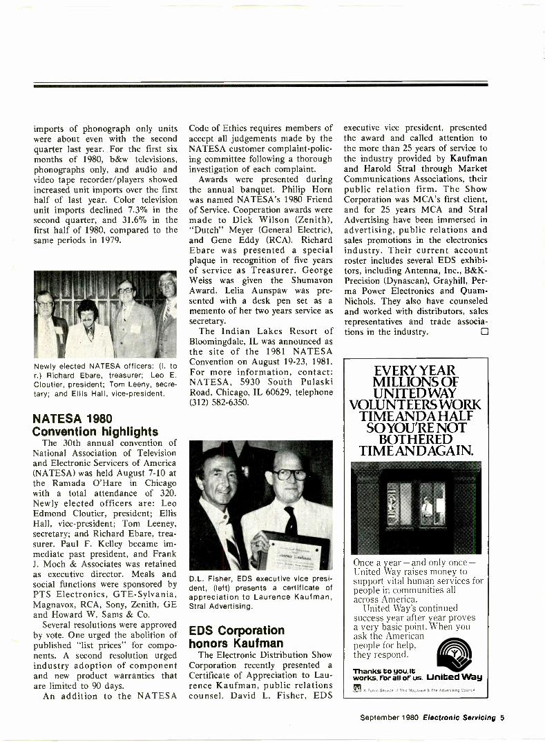
Newly elected NATESA officers: (I. tor.) Richard Ebare, treasurer; Leo E.Cloutier, president; Tom Leeny, secre-tary; and Ellis Hall, vice-president.
NATESA 1980Convention highlights
The 30th annual convention ofNational Association of Televisionand Electronic Servicers of America(NATESA) was held August 7-10 atthe Ramada O'Hare in Chicagowith a total attendance of 320.Newly elected officers are: LeoEdmond Cloutier, president; EllisHall, vice-president; Tom Leeney,secretary; and Richard Ebare, trea-surer. Paul F. Kelley became im-mediate past president, and FrankJ. Moch & Associates was retainedas executive director. Meals andsocial functions were sponsored byPTS Electronics, GTE -Sylvania,Magnavox, RCA, Sony, Zenith, GEand Howard W. Sams & Co.
Several resolutions were approvedby vote. One urged the abolition ofpublished "list prices" for compo-nents. A second resolution urgedindustry adoption of componentand new product warranties thatare limited to 90 days.
An addition to the NATESA
Code of Ethics requires members ofaccept all judgements made by theNATESA customer complaint -polic-ing committee following a thoroughinvestigation of each complaint.
Awards were presented duringthe annual banquet. Philip Hornwas named NATESA's 1980 Friendof Service. Cooperation awards weremade to Dick Wilson (Zenith),"Dutch" Meyer (General Electric),and Gene Eddy (RCA). RichardEbare was presented a specialplaque in recognition of five yearsof service as Treasurer. GeorgeWeiss was given the ShumavonAward. Lelia Aunspaw was pre-sented with a desk pen set as amemento of her two years service assecretary.
The Indian Lakes Resort ofBloomingdale, IL was announced asthe site of the 1981 NATESAConvention on August 19-23, 1981.For more information, contact:NATESA, 5930 South PulaskiRoad, Chicago, IL 60629, telephone(312) 582-6350.
D.L. Fisher, EDS executive vice presi-dent, (left) presents a certificate ofappreciation to Laurence Kaufman,Stral Advertising.
EDS Corporationhonors Kaufman
The Electronic Distribution ShowCorporation recently presented aCertificate of Appreciation to Lau-rence Kaufman, public relationscounsel. David L. Fisher, EDS
executive vice president, presentedthe award and called attention tothe more than 25 years of service tothe industry provided by Kaufmanand Harold Stral through MarketCommunications Associations, theirpublic relation firm. The ShowCorporation was MCA's first client,and for 25 years MCA and StralAdvertising have been immersed inadvertising, public relations andsales promotions in the electronicsindustry. Their current accountroster includes several EDS exhibi-tors, including Antenna, Inc., B&K-Precision (Dynascan), Grayhill, Per -ma Power Electronics and Quam-Nichols. They also have counseledand worked with distributors, salesrepresentatives and trade associa-tions in the industry.
EVERY YEARMILLIONS OFUNITED WAY
VOLUNTEERS WORKTIME ANDA HALF
SO YOU'RE NOTBOTHERED
TIME ANDAGAIN.
Once a year -and only once-United Way raises money tosupport vital human services forpeople in communities allacross America.
United Way's continuedsuccess year after year provesa very basic point. When youask the Americanpeople for help,they respond.
Thanks to you, lbworks. For all of us. United Way
VC
rtin A Public Service of This Magazine & Tne Advertising Council
September 1980 Electronic Servicing 5
Symptoms and cures compiled from field reports of recurring troubles
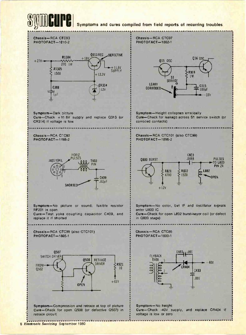
Chassis-RCA CTC93PHOTOFACT-1610-2
+27VR1304
;70 1W
R1305
1500
C388
I 1/CF
Q313 REG DEFECTIVE
+11.6VSUPPLY
4-12.2V
CR314
12V
Symptom-Dark oictureCure-Check +11 6V supply and replace Q313 (orCR314) if voltage is low
Chassis-RCA C -C92PHOTOFACT-1788-2
HORIZPULSES
1401 YOKE0 0 0 -1403
PIN
oQ60±7-----1 0 0 0
C409.62pF
SHORTED
Symptom-No picture or sound; fusible resistorRF201 is openCure-Test yoke coupling capacitor C409, andreplace it if shorted
Chassis-RCA C''C99 (also CTC101)PHOTOFACT-1895-1
Q507
SWITCH DRIVER
FROM
Q502
OPEN
RETRACE
DRIVER R521
+61V
10
Symptom-Compression and retrace at top of pictureCure-Check for open 0508 (or defective Q507) inretrace circuit
Chassis-RCA CTC97PHOTOFACT-1862-1
Q15 OSC
SiSERVICE
LEAKY
CORRODE
Q16 OSC
Rill1M
C115100pF
2V
Symptom-Height collapses erraj7.allyCure-Check for leakage across S" service switch (orcorroded contacts)
Chassis-RCA CTC101 (also CTC99)PHOTOFACT-1896-2
Q800 BURST
C8C3
.0068
R821 R822
4700 1500
+I2V
PULSES
TO U800
L802
"..."`OPEN
Symptom-No color, but IF and oscillator signalsenter U800 ICCure-Check for open L802 burst-keyer coil (or defectin Q800 stage)
Chassis-RCA CTC85PHOTOFACT-1800-1
FLYBACKT401 5
40V
Symptom-No heightCure-Check -40V supply, and replace CR404 ifvoltage is low or zero
6 Electronic Servicing Septemoer 1980
HIM in the pews
Martin H. Rubin has been promoted from director ofindustrial electronic services for RCA to division vicepresident, industrial electronic services. He has beenwith RCA for 32 years.
Shure Brothers has announced the appointment ofRobert J. Mataya to market planning coordinator.Previously, Mataya was with C.G. Conn Ltd.
Ed Miller, president of Miller and Associates, hasbeen elected to a newly created seat on the board ofdirectors of the Electronic Industry Show Corporation.He will be involved in the planning of the 1981Electronic Distribution Show scheduled for next Mayin Atlanta.
Margita E. White, an independent consultant andformerly a member of the FCC, has been elected to theboard of directors of ITT.
The Antenna Specialists Co. has appointed CharlesE. Darrow product marketing administrator. Prior tojoining Antenna Specialists, he worked for DentonRadio.
I. Mitchell Kolesaire has been promoted from TVsales administrator to TV sales coordinator for SharpElectronics.
Robert G. Doud has been promoted from supervisorof training to night industrial manager for ITT CannonElectric. Doud replaces Marvin V. Ussery who hasbeen named ITT Cannon area industrial relationsmanager.
Bernard A. Grae has been named director,industrial design for Radio Shack. He had beenmanager, industrial design since joining the companyin 1974.
Steven T. Klein has been promoted to regional salesmanager, central region at Klein Tools. Previously, hewas marketing research manager.
Also at Klein Tools, James A. Mallek has beenpromoted from customer service manager to marketingservices manager.
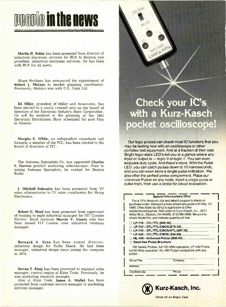
Our logic probes can check most IC functions that youmay be testing now with an oscilloscope or othercomplex test equipment. And at a fraction of their cost.Bright logic -state LED's tell you at a glance where anyinput or output is -logic 0 or logic 1. You can evenevaluate duty cycle. And there's more. With the PulseLED, you can catch pulses down to 10 nanoseconds,and you can even store a single pulse indication. Wealso offer the perfect probe complement. Place ourUniversal Pulser on any node, inject a single pulse orpulse train, then use a probe for circuit evaluation.
Special Introductory OfferE....For a 10% discount, clip and attach coupon to check or
purchase order. Discount prices shown are good until Dec. 31,1980. Ohio State tax (5%) is applicable to Ohioresidents/companies. Mail order to Kurz-Kasch, Inc., 2271Arbor Blvd., Dayton, OH 45439, 513/299-0990. Be sure tocheck Model No. and indicate quantity on line.
LP -710 - DTL/TTL ($60.50)12 LP -750 - DTL/TTL/CMOS ($78.50)CI LP -770 - DTL/TTL/CMOS/HTL ($87.50)
LP -450- DTL/TTL/CMOS ($56.00) HL -480 - Universal Pulser ($56.00)LI Send free Probe Brochure
700 Series Probes, full 100 -MHz operation. LP -450 Probe,full 50 -MHz operation. HL -480 Pulser compatible with anyprobe.
Name/Title Company
Address
City/State/Zip Phone
® Kurz-Kasch, Inc.Circle (4) on Reply Card
Industrial MRO
0
test labEach report about an item ofelectronic test equipment isbased on examination andoperation of the device in theELECTRONIC SERVICINGlaboratory. Personalobservations about theperformance, and details ofnew and useful features arespotlighted along with tipsabout using the equipment forbest results.
By Carl Babcoke, CET
Sencore model PR -57 AC Power-ite (Figure 1) has four separate ac -power functions. First, it includesan isolation transformer. When ahot -chassis television receiver isoperated from an isolated windingof a line -voltage transformer, testequipment having grounded three -prong ac plugs can be connected tothe TV without danger to receiveror equipment. Without an isolationtransformer, both test equipmentand receiver can be damaged bycertain connections that might re-sult in unexpected shocks. ThePR -57 has only one three -prongoutput socket. This prevents acci-dental defeat of the safety featurethat would occur if one item of testequipment was plugged into theisolated socket (along with a hot -chassis television) and then another
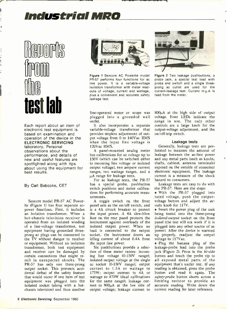
Figure 1 Sencore AC Powerite modelPR -57 performs four functions for acline power. It is a variable -voltageisolation transformer with meter read-outs of voltage, current and wattage,plus a convenient and accurate safetyleakage test.
line -operated meter or scope wasplugged into a grounded walloutlet.
It also incorporates a separatevariable -voltage transformer thatprovides stepless adjustment of out-put voltage from 0 to 140Vac RMSwhen the input line voltage is120Vac RMS.
A panel -mounted analog meterhas calibrations for ac voltage up to150V (which can be switched eitherto incoming line voltage or isolatedoutput voltage), two ampere currentranges, two wattage ranges, and a1,LA range for leakage tests.
For ac leakage tests, the PR -57has a special probe, pushbuttonswitch positions and meter calibra-tions for performing accurate meas-urements.
A toggle switch on the frontpanel acts as the on/off switch, andis a 4A circuit breaker to protectthe input power. A 4A slow -blowfuse on the rear panel protects theinstrument against overloads of theisolated output power. When noload is connected to the outputsocket, the instrument draws anidling current of about 0.4A fromthe input line power.
Six pushbuttons provide a selec-tion of these meter rantes: incom-ing line voltage (0-150V range);isolated output voltage at the singleac socket (0-150V range); outputcurrent to 1.5A or wattage to175W; output current to 4A orwattage to 470W (dual calibrationsfor the same range); leakage cur-rent to 800HA at the low side ofoutput voltage; leakage current to
Figure 2 Two leakage pushbuttons, aprobe jack, a special test lead withprobe and switch and a single three -prong ac outlet are used for thecurrent -leakage test. Current in p,A isread from the meter.
800pA at the high side of outputvoltage. Four LEDs indicate therange in use. The only othercontrols are a large knob for theoutput -voltage adjustment, and theon/off-trip switch.
Leakage testsGenerally, leakage tests are per-
formed to measure the amount ofleakage between the ac -line powerand any metal parts (such as knobs,shafts, cabinet, antenna terminals)exposed on the outside of consumerelectronic equipment. The leakagecurrent is a measure of the shockhazard to consumers.
Leakage tests are easy to do withthe PR -57. Here are the steps: With the PR -57 plugged intorated voltage, push the output -voltage button and adjust the ac -volts knob for 117V. Insert the power plug of the unitbeing tested into the three -prongisolated -output socket on the frontpanel (the test will not work if it isplugged into any other source of acpower). After the device is warmedup properly, readjust the outputvoltage to 117Vac. Plug the banana plug of theleakage -probe lead into the probejack (Figure 2). Press in the hi -sidebutton and touch the probe tip toall exposed metal parts of theequipment that's under test. If anyreading is obtained, press the probebutton and read it again. Thesafety -probe button shorts across alimiting resistor to provide anaccurate reading. Write down thecurrent reading for later reference.
8 Electronic Servicing September 1980

SAFETY CERTIFIEDAll exposed metal has been tested with aSencore PR57 Safety Analyzer and found tohave leakage below the level considered safeby Underwriter Laboratories for this type ofchassis.
Max. Allowable Leakage uAMax. Measured uATest DateTested BySerial #Form 66K254
Figure 3 Two banners, one ad slick,and one roll of 100 safety labels (asshown) are packed with each PR -57.These aids help educate the public tothe value of safety leakage tests, andcan be used as business builders.Courtesy of Sencore.
Press in the lo -side pushbuttonand repeat the test, writing downany readings obtained.
Current readings must be evalu-ated to determine whether they are
Figure 4 Operation of an RCA CTC99 from a Sencore PR -57 produced thesewaveforms. (A) Top trace shows the TV power voltage before the switch wasturned on. The bottom trace shows the soft clipping of all peaks from thepulses of current. Scope adjustments (except centering) were not changedbetween photographs. (B) Both waveforms by camera double exposure prove thedistortion and loss of amplitude occur only at the tips. This can result in lowerB+ voltages in the TV, unless the line voltage is readjusted.
safe or dangerous. The Sencoremanual gives approximate limits.
Selling safety testsSencor2 supplies with each
Powerite several items of supportmaterial for selling safety testsusing the PR -57, including a roll of100 labels (Figure 3) that can beattached to the tested device.
Peopleof allages die ofheart disease
and stroke.
Put your money whereyour Heart is.
tiPAssociation
AmericanHeart
WE'RE FIGHTING FOR YOUR LIFE
32 job -matched specialty pliers forelectronics workers. They feelright. They work right. Klein toolsfor professionals. You can buythem from authorized Klein dis-tributors in your area. . .atcompetitive prices.
KLEINHand me the Kleins. ..since 1857.
Sendfor ri 6,
Catalog !-"'
Klein Tools, Inc. 7200 McCormick, Chicago, III. 60645
6-238
Circle (5) on Reply Card
Septem ber 1980 Electronic Servicing 11
Test lab
Sencore recommends making acharge for these safety tests.
Accuracy ratingsAccuracy of the 150Vac range for
input and output voltages is ratedat .±_3% of full scale. All othercurrent and wattage ranges also arerated at ±3% of full scale. Wattagereadings are obtained by multipli-cation of voltage times current, andare accurate only at 117V.
Waveform distortionEvery isolation transformer tested
so far in the Electronic Servicinglaboratory has exhibited roundedsinewave peaks at the secondarywinding when the sole load was amodern solid-state TV receiver.Evidently, this is a general condi-tion, and is not a complaint againstthe Powerite, which also hasrounded peaks (Figure 4).
Each new TV receiver has abridge rectifier that draws currentfrom the power line only at thepositive and negative tips of thesinewaves. There is no other loadon the ac -power source; maximumcurrent flows during these shorttime periods, and zero current flowsbetween the current pulses.
Because these current pulsesmust be averaged to obtain actualpower, the ratio of peak to averagecurrent is unfavorable. For ex-ample, if the receiver requires120W and the current flows for25% of the time, each conductionmust supply 4A, and not 1A asrequired for continuous current.This large peak current produces avoltage loss in the isolation trans-former windings solely during the
tips of positive and negative peaks.There is no voltage drop at othertimes. The result is soft clipping(rounding) of all sinewave tips.
Minor power -line distortion frompulsed current would present noproblems with resistive loads (suchas tube heaters). They operate fromthe waveform's RMS value, sodistortion is not important. Increas-ing the voltage to provide thecorrect RMS value would be suffici-ent.
Unfortunately, peak -reading di-ode/capacitance rectifier systemsproduce output voltages in directproportion to the peak -to -peak linevoltage. Of course, rounding thepeaks reduces the peak -to -peakamplitude along with the dc voltagefrom any line -operated power sup-ply.
Tests were conducted on an RCACTC99 (which drew 105W, accord-ing to the PR -57) with scope and aSencore model DVM-56, chosenbecause it has very accurate peak -to -peak, average and true-RMS acmeasurements. Bridge rectifier (hotsupply nonregulated) dc voltages inthe television were measured withrounded and nonrounded powerwaveforms. Table 1 lists some ofthese measurements.
The PR -57 line -voltage meterreads the so-called average value;meter calibrations are adjusted forsine waves. Most readings will beabout the same as RMS unless thewaveforms are badly distorted.Therefore, slight clipping of peakswill affect the voltage readings inreceivers more than it affects thePR -57 meter reading.
Calibration of the sample PR -57line -voltage function measuredabout -4% at the 117V mark on themeter. (Model DVM-56 and other
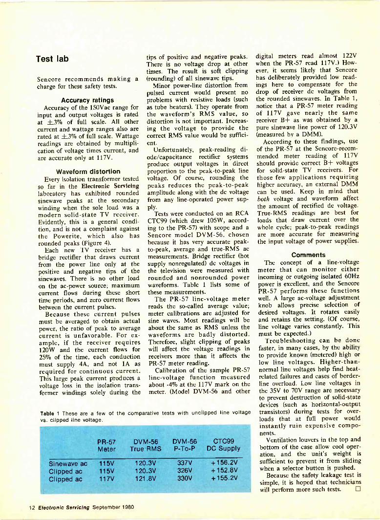
Table 1 These are a few of the comparative tests with unclipped line voltagevs. clipped line voltage.
PR -57 DVM-56 DVM-56 CTC99Meter True RMS P -To -P DC Supply
Sinewave ac 115V 120.3V 337V +156.2VClipped ac 115V 120.3V 326V +152.8VClipped ac 117V 121.8V 330V +155.2V
digital meters read almost 122Vwhen the PR -57 read 117V.) How-ever, it seems likely that Sencorehas deliberately provided low read-ings here to compensate for thedrop of receiver dc voltages fromthe rounded sinewaves. In Table 1,notice that a PR -57 meter readingof 117V gave nearly the samereceiver B+ as was obtained by apure sinewave line power of 120.3V(measured by a DMM).
According to these findings, useof the PR -57 at the Sencore-recom-mended meter reading of 117Vshould provide correct B+ voltagesfor solid-state TV receivers. Forthose few applications requiringhigher accuracy, an external DMMcan be used. Keep in mind thatboth voltage and waveform affectthe amount of rectified dc voltage.True-RMS readings are best forloads that draw current over thewhole cycle; peak -to -peak readingsare more accurate for measuringthe input voltage of power supplies.
CommentsThe concept of a line -voltage
meter that can monitor eitherincoming or outgoing isolated 60Hzpower is excellent, and the SencorePR -57 performs these functionswell. A large ac -voltage adjustmentknob allows precise selection ofdesired voltages. It rotates easilyand retains the setting. (Of course,line voltage varies constantly. Thismust be expected.)
Troubleshooting can be donefaster, in many cases, by the abilityto provide known (metered) high orlow line voltages. Higher -than -normal line voltages help find heat -related failures and cases of border-line overload. Low line voltages inthe 35V to 70V range are necessaryto prevent destruction of solid-statedevices (such as horizontal -outputtransistors) during tests for over-loads that at full power wouldinstantly ruin expensive compo-nents.
Ventilation louvers in the top andbottom of the case allow cool oper-ation, and the unit's weight issufficient to prevent it from slidingwhen a selector button is pushed.
Because the safety leakage test issimple, it is hoped that technicianswill perform more such tests. El
12 Electronic Servicing September 1980
Industrial MRO
The basic design of logic probes
By James W. Sneed, Jr., director, R & D, Kurz-Kasch, Dayton, OH.
Logic probes, relatively recent to the instrumentation field,provide a powerful test tool and an inexpensive alternative tousing a traditional oscilloscope. The author, holder of the patentfor the dual -threshold logic probe, reviews his company'scontinued attention to logic probe development and reviewshistorical developments in this field.
The ultimate instrument for digi-tal testing is a wide -band scope.The scope should have a bandwidthof at least four times the highestfrequency involved.
Scopes have the ability to showgraphically the signals needed to beobserved, often a primary require-ment in test equipment. The dis-plays of any piece of test equipmentmust be able to translate for the"mind's eye" just what is occurringat the test point.
Scopes are the best for this butaren't used exclusively because ofportability, cost, inability to analyzeand speed with which multipleobservations must be made.
Logic probes were invented toovercome these four disadvantagesof the scope. The probe won't doall the scope will do. However, ifthe probe will do the necessary testindications for digital servicing, it isan acceptable substitution.
The Kurz-Kasch logic probe, forexample, is designed to approachthe scope in display. Needed pa-rameters are displayed on theKurz-Kasch probe: low, highs,deadband, pulses (logic state transi-tions), pulse repitition rate and dutycycle.
In the Kurz-Kasch probe, thesedisplay parameters are achieved bythree independent lights; One is foreach basic parameter, low state,high state and transitions. There isno sharing of display functions.
A major consideration in any testequipment is that its display beconsistent. For example, in aDVOM, the display digits shouldread left to right and for volts,ohms and current. The K -K probeis consistent this way in its presen-
tation. For example, the "0" LEDdisplays all parameters of the lowstate, valid low, relative dwell timeand off. The same is true for the"1" LED (high) and logic transition(pulse) LED.
Kurz-Kasch, as a matter ofdetermining its competitive posi-tion, regularly evaluates these pa-rameters:a. Clarity and readibility of its
indicators;b. Consistency of display;c. Speed capability-the true cap-
ture speed of a probe is deter-mined by the one shot mode.This is a single pulse, bothpositive and negative going, of awidth specified: 5ns, lOns, etc;The speed of any probe isdetermined by its components.CMOS devices usually are in the50-400ns speed range. Kurz-Kasch uses devices capable ofconsistent 5ns speeds;
1
d. Duty cycle-must show dutycycle from at least 10:1 over itsoperating range, DC to capturespeed (usually lOns); and
e. Construction and repairability.Continued attention to quality incomponents, materials, workman-ship and circuitry provides userswith logic probes to best serve theirneeds.
This probe incorporates the ex-clusive dual threshold pulse circuit,giving technicians an added dimen-sion in troubleshooting.
A small button at the forwardend of the label, in the up position,allows the probe to operate as asingle threshold probe (just likeprevious ones). When the button isdepressed, the system becomes adual -threshold probe.
The following figures explain theoperation of this feature.
/.8VOV
2
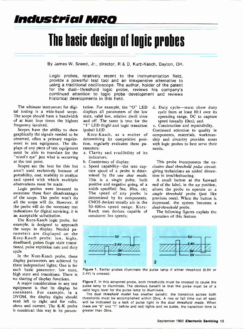
Figure 1. Earlier probes illuminate the pulse lamp if either threshold (0.8V or2.4V) is crossed.
Figure 2. In this advanced probe, both thresholds must be crossed to cause thepulse lamp to illuminate. The obvious benefit is that the pulse must be of avalid logic level for the pulse lamp to illuminate.
The dual threshold model has another benefit: the transition across boththresholds must be accomplished within 35ns. A rise or fall time out of specwill be indicated by a lack of pulse light in the dual threshold mode. Whenthere are "0" and "1" (white and red) lights and no pulse, the transition time isgreater than 35ns.
September 1980 Electronic Servicing 13
Probe design
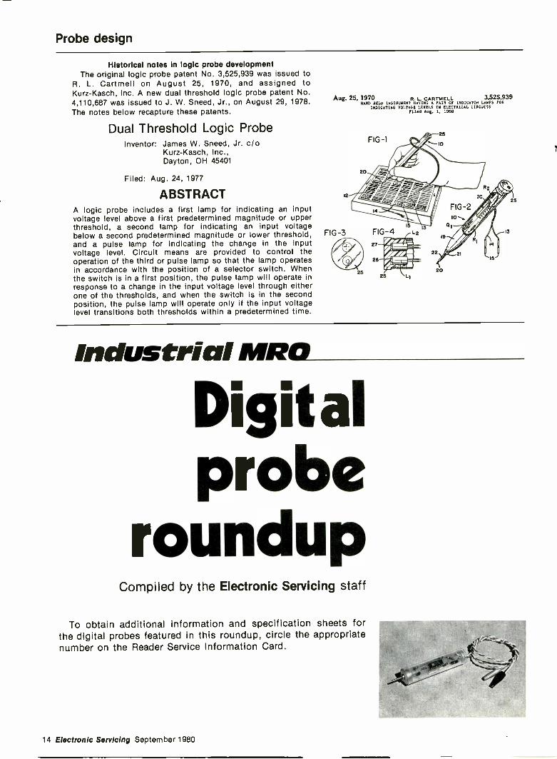
Historical notes In logic probe developmentThe original logic probe patent No. 3,525,939 was issued to
R. L. Cartmell on August 25, 1970, and assigned toKurz-Kasch, Inc. A new dual threshold logic probe patent No.4,110,687 was issued to J. W. Sneed, Jr., on August 29, 1978.The notes below recapture these patents.
Dual Threshold Logic ProbeInventor: James W. Sneed, Jr. c/o
Kurz-Kasch, Inc.,Dayton, OH 45401
Filed: Aug. 24, 1977
ABSTRACTA logic probe includes a first lamp for indicating an inputvoltage level above a first predetermined magnitude or upperthreshold, a second lamp for indicating an input voltagebelow a second predetermined magnitude or lower threshold,and a pulse lamp for indicating the change in the inputvoltage level. Circuit means are provided to control theoperation of the third or pulse lamp so that the lamp operatesin accordance with the position of a selector switch. Whenthe switch is in a first position, the pulse lamp will operate inresponse to a change in the input voltage level through eitherone of the thresholds, and when the switch is in the secondposition, the pulse lamp will operate only if the input voltagelevel transitions both thresholds within a predetermined time.
Aug. 25, 1970 R. CARTMELL 3,525,939NAND HELD INSTRUMENT HAVING A PAIR OF INDICATOR LAMPS FOR
INDICATING VOLTAGE LEVELS IN ELECTRICAL CIRCUITSF11md Aug. 1. 1968
Industrial MRO
Digitalprobe
roundupCompiled by the Electronic Servicing staff
To obtain additional information and specification sheets forthe digital probes featured in this roundup, circle the appropriatenumber on the Reader Service Information Card.
14 Electronic Servicing September 1980
ADVA ElectronicsModel LP -10 logic probe features
multi -family compatibility (RTL,DTL, TTL, HTL, NiNLL andCMOS), high -input impedance(20M s2), LED logic 0 and logic 1indicators, and reverse polarity andover -voltage protection. Operatingvoltage range is 3V to 15V.
The LP -10 is available in kitform at $9.95. The assembledversion is $14.95.
Circle (15) on Reply Card
--A1111111111111111M
AlcoliteModel 3100A logic probe per-
forms as a level detector, pulsedetector, pulse stretcher and memo-ry probe. The unit gives instantpositive indication of circuit condi-tions, and captures one-shot andlow -rep -rate pulses. LEDs indicatelogic 1 and logic 0 and all pulsetransitions. Optional accessories in-clude ground lead.
Circle (16) on Reply Card
B&K-PrecisionModel DP -50 digital probe is
multi -family compatible with TTL,DTL, RTL, HTL, CMOS, MOSand HiNIL. The unit displays dc to50MHz, pulse presence and logicstates. Features include memoryand pulse modes, 2M S2 impedance,and input overload protection.
Circle (17) on Reply Card
Model DP -100 digital pulse probecan be used alone, or in conjunc-tion with a logic probe or scope.The DP -100 generates a one-shot inthe single pulse mode or a continu-ous pulse train in the 5Hz outputmode. It automatically senses logicstate and changes state to itscompliment. The unit features over-load protection and is compatiblewith TTL, MOS, CMOS and HiNILlogic circuits.
The price of the CP-100 is $95.Circle (18) on Reply Card
E&L InstrumentsModel LT -2 dual -state logic
probe features two LEDs to indicatelogic states. A switchable pulsestretch mode captures pulses asnarrow as 5Ons. The LT -2 obtains5Vdc for operation through at-tached clip leads. Two probe tipsare supplied.
Circle (19) on Reply Card
Electro IndustriesModel 300 logic probe offers
12MHz frequency response, high -input impedance and polarity rever-sal protection. Measurement capa-bilities extend to TTL, and DTLsystems, flip-flops, counters anddecoders.
Circle (20) on Reply Card
Model 330 logic probe displayslogic states by red and green LEDindicators. A switch -selected pulsestretch (storage) mode allows pulsesas narrow as 5Ons and high speedpulse trains up to 12MHz to beobserved. Other features includehigh -input impedance, and overload
and reverse polarity protection. Twoscrew -on probe tips and carryingcase are supplied with the unit.
Circle (21) on Reply Card
Model 340 logic pulser/probefeatures two modes of operation:when switched to the on mode, itoperates as a single -shot pulser andcan change logic states by injectingpulses into the circuit under test. Inthe off position the unit will detectshort pulses and logic high statesemploying green and red LEDs asreadouts. The power supply unit,pulse output and probe are pro-tected against overvoltage, includingpower lead reversal.
Circle (22) on Reply Card
FlukeThe 200 Series IC testclip multi-
ple -use logic testers combine thefunctions of three instruments:logic probe, logic states clip and in -circuit IC comparator. Thresholdsare detected automatically, andpower is derived from the unitunder test. DTL, TTL, CMOS andHTL compatible versions are avail-able.
Circle (23) on Reply Card
Global SpecialtiesModel LP -1 logic probe combines
the functions of a level detector,pulse detector, pulse stretcher andpulse memory. The unit featuresdual -threshold window compara-tors, bipolar edge detection, pulse
September 1980 Electronic Servicing 15
stretcher, front ground connectorlead and switch -selected pulsememory. Instruction manual, probetip and power cable are included.
The LP -1 is available for $50.Circle (24) on Reply Card
Model LP -2 identifies valid andinvalid logic states, detects andstretches pulses, and permits ap-proximation of pulse duty cyclewhen observing pulse trains. Theunit features a front ground con-nector lead. Instruction manual,probe tip and power cable areincluded.
The price of the LP -2 is $28.Circle (25) on Reply Card
Ittri
4111111111ftesimai
Model LP -3 logic probe is capa-ble of capturing pulses as narrow as6ns (typical, 100% tested at lOns) orpulse trains to more than 70MHz.The LP -3 features pulse memoryand a front ground connector lead.Instruction manual, front groundlead, probe tip and power lead areincluded.
The price of the LP -3 is $77.Circle (26) on Reply Card
Hewlett-PackardModel 547A current tracer senses
logic current pulses as small aslmA, up to 5mm from the conduc-tor. The tracer operates on all logicfamilies having current pulses fromlmA to 1A with repetition rates upto 10MHz. Self-contained in ahand-held probe, the 547A operatesfrom 4.5 to 18Vdc; current requiredis less than 75mA. The indicatorlamp will display single-step currenttransitions, single pulses greaterthan 50 ns wide and pulse trains to10MHz. Current transitions withrisetimes less than 200ns at lmAare displayed.
The 547A's price is $350.Circle (27) on Reply Card
Model 546A logic pulser electri-cally stimulates integrated circuitsof most positive -voltage logic fami-lies (TTL, DTL, RTL, HTL andCMOS). The unit will drive highnodes low, or low nodes high over awide range of supply voltages. Sixoutput pattern choices are featuredthat provide a single pulse, a 100Hzcontinuous pulse stream, 100 -pulsebursts, a 10Hz continuous pulsestream, 10 -pulse bursts, or a 1Hzcontinuous pulse stream.
Operating voltage for TTL fami-lies is 5± 10% Vdc and for CMOSis 3 to 18Vdc. Operating current isless than 35mA. Time base accura-cy is ±10%.
The 546A's price is $150.Circle (28) on Reply Card
HeathIT-7410/ST-7410 logic probes are
designed for in -circuit testing ofTTL and CMOS integrated circuits.Features include switch selection ofthreshold levels for either TTL orCMOS circuitry and lamps thatturn on when the input voltagecrosses the appropriate level. Amemory circuit is incorporated inthe design of the unit to turn on anLED when either threshold level iscrossed. Both probes provide truelogic level detection at high fre-quencies (not ac -coupled) and willdetect pulses as short as lOns.Upper frequency limits are 100MHzand 80MHz. Power is drawn fromthe circuit under test. A groundlead is provided. Overload protec-tion is 50Vdc continuous and175Vdc for 5 -seconds. The IT -7410is the kit version and the ST -7410is assembled.
The prices are $39.95 for the kitand $64.95 assembled.
Circle (29) on Reply Card
IFI-1)
IMO
Kurz-Kasch700 Series logic probes and
model LP -450 logic probe and theHL -480 universal pulser have logic1 and logic 0 LEDs for logic stateindication and a Pulse LED fordetecting pulse trains. The PulseLED operates from a 50ms pulse -stretching circuit for clear indica-tion of single pulses down to lOnspulse width. A Memory switchallows storage of single pulseevents. Operating frequency of theprobes is to 100MHz. Tip andpower leads have high -voltage pro-tection with auto shutdown. TheLP -750 is designed to check multi-ple logic families. It can be used totest TTL/DTL and CMOS families.The LP -770 can also test HTLfamilies. The probes derive powerfrom the circuit under test, andlogic family thresholds are pro-grammed with switches on theprobe nameplate. The 700 seriesprobes provide a special plug-inassembly that can connect twonodes to the probe. The probesfeature logic -state analysis, pulsedetection, pulse stretching, pulsememory, versatile TTL/DTL andCMOS testing and frequency re-sponse to 50MHz.
The 700 Series Probes are pricedfrom $65 to $95. The LP -450 ispriced at $60.
Circle (30) on Reply Card
Non Linear SystemsModel MLB-1 digital logic probe
is TTL, DTL or CMOS switch -selectable. Available modes includepulse and memory. The unit fea-
16 Electronic Servicing September 1980
tures high and low LED stateindicators and a flashing pulseindicator. The high and low indica-tors provide analytical indicationsin the dynamic testing of pulsetrains and rectangular waveformsup to 10MHz. Minimum pulsewidth is 5Ons.
The MLB-1 can be powered fromthe supply of the circuit under test,or from an external supply. Thres-hold voltages for each kind of logicare the go/no-go comparison limitsfor high and low states.
The Model MLB-1 is priced at$41.95.
Circle (31) on Reply Card
AnalF11117 1 I I I 3 OD
O.K. Machine and ToolModel PRB-1 digital logic probe
detects pulses as short as lOns, hasfrequency response to better than50MHz and automatic pulsestretching to 5Ons (+ and -). Theunit is compatible with RTL, DTL,HTL, TTL, MOS, CMOS andmicroprocessor logic families. Italso features 120K impedance,power lead ,reversal protection andovervoltage protection to 200V(+-V). Optional PA -1 adapter foruse with supply voltages 15-25V.Includes 6 -foot coiled power cordand tip protector. Troubleshootinginstruction booklet and case areincluded.
The PRB-1 is priced at $36.95.Circle (32) on Reply Card
Model PLS-1 logic pulser is amulti -mode, high current pulsegenerator packaged in a hand-heldshirt pocket portable instrument. Itcan source or sink sufficient currentto force saturated output transistorsin digital circuits into the oppositelogic state. Signal injection is bymeans of a pushbutton switch nearthe probe tip. When the button isdepressed, a single high -going orlow -going pulse of 2 µ sec wide isdelivered to the circuit node under
test. Pulse polarity is automatic.Holding the button down delivers aseries of pulses at 20pps to thecircuit under test.
PLS-1 is suited for use inconjunction with the PRB-1 probeand costs $48.95.
Circle (33) on Reply Card
SanseiModel 3300A logic probe is
designed to detect and displaydigital logic levels of DTL/TTL,CMOS and other popular logiccircuits. It provides a IM sz impe-dance, and is capable of makingprecise measurements without af-fecting circuits under test. Tominimize reading errors in leveldetections, two LEDs are used. Theunit operates at 5Vdc to 18Vdc andis protected against reverse powersupply and input over voltage.
Circle (34) on Reply Card
TektronixModel P6401 logic probe indi-
cates the state of logic levels inTTL, DTL or any other system withthreshold between 0.7V and 2.15V.A strobe input can be used todetect the coincidence of logicsignals at two points. A store modeprovides an indication of whetheror not a logic pulse has occurred.Power may be obtained from theunit under test or any 5V supply.The P6401 includes hook tip, twostrobe leads, probe tip to 1/4 -inch insquare pin adapter, white plug, twoalligator clips and accessory pouch.
The price of the P6401 is $105.Circle (35) on Reply Card
Wandel & GoltermannModel TKL-515 digital probe
permits determination of logicstates in the TTL, CMOS and otherrelated logic families. The high andlow levels are displayed, but thethresholds needed for particularapplications can also be individuallyadjusted. The unit also features amemory. The TKL-515 is protectedagainst false polarity and overvol-tage.
Circle (36) on Reply Card 0
APPLIANCEREPAIRBOOKS
Thirteen Handbooks written in easy -to -under-stand language by experts in the service fieldwith illustrations and diagrams! Acclaimed byinstructors and professionals alike! How todiagnose and repair air conditioners, refrigera-tors, washers, dryers, ranges, microwaveovens, dishwashers, vacuum cleaners, electro-static air cleaners, RV gas appliances, hairdryers, motors, water heaters, coffeemakers,can openers, floor polishers, steam irons, foodmixers, lawn care appliances, electric knives,electric and digital clocks and many others.Also fundamentals of solid state, setting up ashop, using test instruments and more Only$2.65 to $4.90 ea.
SENO FOR FREE PRICE LIST
Gamit, Dept. ES110 W. St. Charles Road,Lombard, Illinois 60148
Circle (6) on Reply Card
NATIONAL ELECTRONICSSERVICE DEALERS
aAre you standingidly by while ideasthat can bemoney in your -pocket fly away/Membership in NESDAis one of those ideas.
WHAT DO YOU GET FROM NESDA71. Insurance2. Special Bancard Rates ,i1731,----,3. ServiceShop Magazine ' --......4g,..,4. Electronic Service %
k :Industry Yearbook ...-,,r0 iv,5. Service Industry Informatio
6. Legislative Programs with ,a1.1A_. ,___.State and National Governmer
7. Advocate for Better IWO'Warranty Practices
8. Business InformationVivi
Don't let yourbucks get lost inthe shuffle.
Send in your checktoday.
On the bottom lineit will mean extra $$$ in your pocket.
JOIN NESDA'St.csomukAnd Your State Association
Send for more information: t t,NESDA, 2708 W. Berry St. 1IrFort Worth, TX 76109 _64r
now'
Circle (7) on Reply Card
September 1980 Electronic Servicing 17
Consumer ServicingTroubleshooting
digital equipmentTypes of integrated -circuit defects and methods of testing forthem are discussed.
By John E. CunninghamJ. E. Cunningham Associates
Important changes in trouble-shooting methodology are necessaryfor any technician who was experi-enced with analog circuitry but nowis beginning to repair troubles indigital equipment. First of all, thesignals are different.
Analog signals change amplitudeduring each cycle. Analog ac signalsoften ride on dc voltage. But digitalsignals are pure dc voltage. Asimple digital signal can be apositive voltage that is almost ashigh as the supply voltage (logichigh), or it might be almost zerovolts (logic low). Even digital pulsesare merely slices of dc voltage withzero as reference. Digital signalsmight change state (high to low, orlow to high) only once in severalminutes (dc control voltages) orcontinuously at nanosecond ratewhen in a digital computer.
Another important difference be-tween analog and digital involvesthe phase (arrival time) of twosignals. Few analog signals requirea phase comparison. Certain digitalgates require the input signals toarrive at precisely the same time. Ifone gate signal arrives too soon or
4K
INPUT AINPUT 8
TTL GATE INPUT
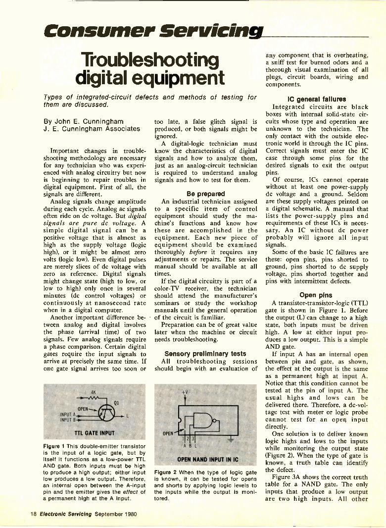
Figure 1 This double -emitter transistoris the input of a logic gate, but byitself it functions as a low -power TTLAND gate. Both inputs must be highto produce a high output; either inputlow produces a low output. Therefore,an internal open between the A -inputpin and the emitter gives the effect ofa permanent high at the A input.
too late, a false glitch signal isproduced, or both signals might beignored.
A digital -logic technician mustknow the characteristics of digitalsignals and how to analyze them,just as an analog -circuit technicianis required to understand analogsignals and how to test for them.
Be preparedAn industrial technician assigned
to a specific item of controlequipment should study the ma-chine's functions and know howthese are accomplished in theequipment. Each new piece ofequipment should be examinedthoroughly before it requires anyadjustments or repairs. The servicemanual should be available at alltimes.
If the digital circuitry is part of acolor -TV receiver, the technicianshould attend the manufacturer'sseminars or study the workshopmanuals until the general operationof the circuit is familiar.
Preparation can be of great valuelater when the machine or circuitneeds troubleshooting.
Sensory preliminary testsAll troubleshooting sessions
should begin with an evaluation of
OPEN
+V
2 3
A B L
OPEN NAND INPUT IN IC
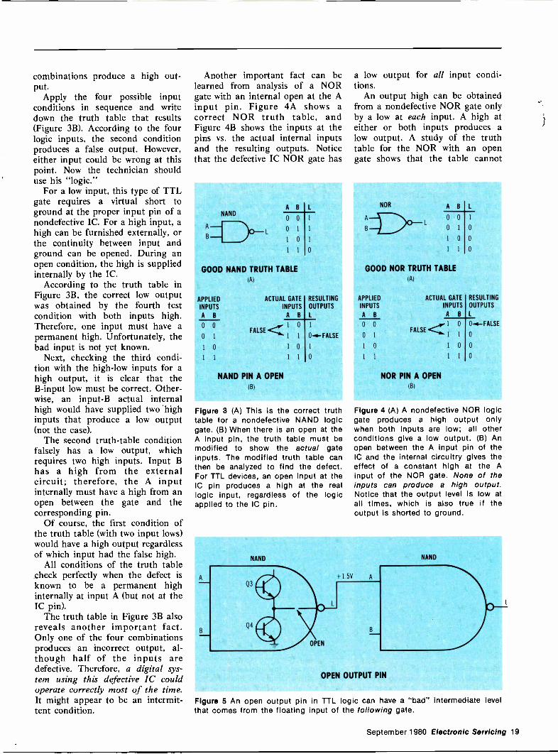
Figure 2 When the type of logic gateis known, it can be tested for opensand shorts by applying logic levels tothe inputs while the output is moni-tored.
any component that is overheating,a sniff test for burned odors and athorough visual examination of allplugs, circuit boards, wiring andcomponents.
IC general failuresIntegrated circuits are black
boxes with internal solid-state cir-cuits whose type and operation areunknown to the technician. Theonly contact with the outside elec-tronic world is through the IC pins.Correct signals must enter the ICcase through some pins for thedesired signals to exit the outputpins.
Of course, ICs cannot operatewithout at least one power -supplydc voltage and a ground. Seldomare these supply voltages printed ona digital schematic. A manual thatlists the power -supply pins andrequirements of these ICs is neces-sary. An IC without dc powerprobably will ignore all inputsignals.
Some of the basic IC failures arethese: open pins, pins shorted toground, pins shorted to dc supplyvoltage, pins shorted together andpins with intermittent defects.
Open pinsA transistor -transistor -logic (TTL)
gate is shown in Figure 1. Beforethe output (L) can change to a highstate, both inputs must be drivenhigh. A low at either input pro-duces a low output. This is a simpleAND gate.
If input A has an internal openbetween pin and gate, as shown,the effect at the output is the sameas a permanent high at input A.Notice that this condition cannot betested at the pin of input A. Theusual highs and lows can bedelivered there. Therefore, a dc -vol-tage test with meter or logic probecannot test for an open inputdirectly.
One solution is to deliver knownlogic highs and lows to the inputswhile monitoring the output state(Figure 2). When the type of gate isknown, a truth table can identifythe defect.
Figure 3A shows the correct truthtable for a NAND gate. The onlyinputs that produce a low outputare two high inputs. All other
18 Electronic Servicing September 1980
combinations produce a high out-put.
Apply the four possible inputconditions in sequence and writedown the truth table that results(Figure 3B). According to the fourlogic inputs, the second conditionproduces a false output. However,either input could be wrong at thispoint. Now the technician shoulduse his "logic."
For a low input, this type of TTLgate requires a virtual short toground at the proper input pin of anondefective IC. For a high input, ahigh can be furnished externally, orthe continuity between input andground can be opened. During anopen condition, the high is suppliedinternally by the IC.
According to the truth table inFigure 3B, the correct low outputwas obtained by the fourth testcondition with both inputs high.Therefore, one input must have apermanent high. Unfortunately, thebad input is not yet known.
Next, checking the third condi-tion with the high -low inputs for ahigh output, it is clear that theB -input low must be correct. Other-wise, an input -B actual internalhigh would have supplied two highinputs that produce a low output(not the case).
The second truth -table conditionfalsely has a low output, whichrequires two high inputs. Input Bhas a high from the externalcircuit; therefore, the A inputinternally must have a high from anopen between the gate and thecorresponding pin.
Of course, the first condition ofthe truth table (with two input lows)would have a high output regardlessof which input had the false high.
All conditions of the truth tablecheck perfectly when the defect isknown to be a permanent highinternally at input A (but not at theIC pin).
The truth table in Figure 3B alsoreveals another important fact.Only one of the four combinationsproduces an incorrect output, al-though half of the inputs aredefective. Therefore, a digital sys-tem using this defective IC couldoperate correctly most of the time.It might appear to be an intermit-tent condition.
Another important fact can belearned from analysis of a NORgate with an internal open at the Ainput pin. Figure 4A shows acorrect NOR truth table, andFigure 4B shows the inputs at thepins vs. the actual internal inputsand the resulting outputs. Noticethat the defective IC NOR gate has
NANDA B L
0 0 1
0 1 1
1 0 1
1 1 0
GOOD NAND TRUTH TABLE(A)
APPLIED
INPUTS
A B
0 0
0 1
1 0
1 1
ACTUAL GATE
INPUTS
A B
FALSE1 0
1 1
1 0
1 1
NAND PIN A OPEN(o)
RESULTING
OUTPUTS
L
0 -4 -FALSE
1
0
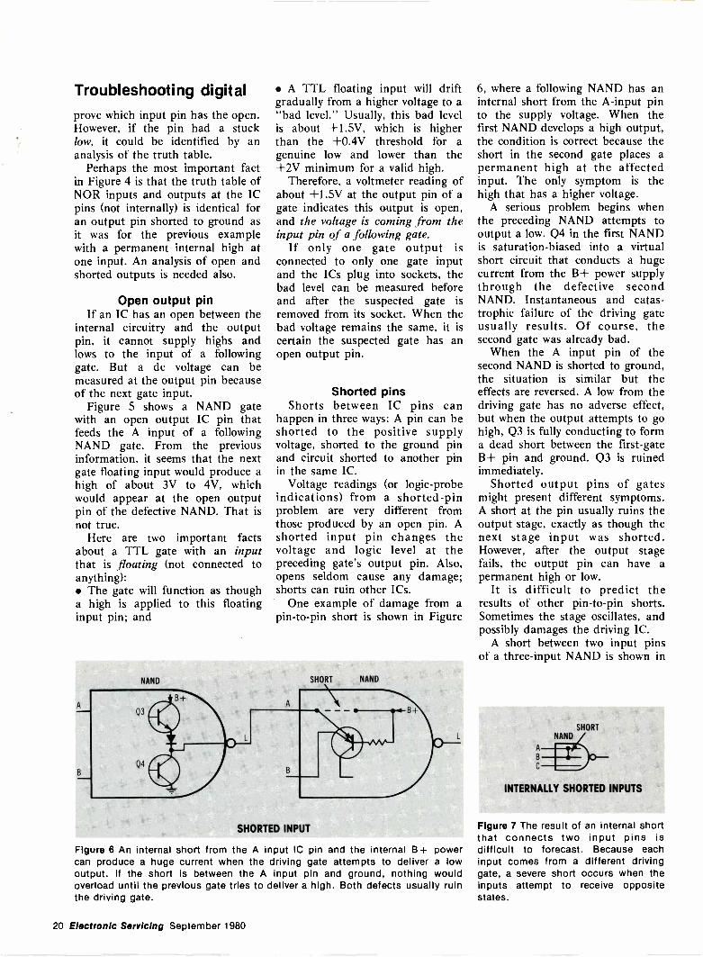
Figure 3 (A) This is the correct truthtable for a nondefective NAND logicgate. (B) When there is an open at theA input pin, the truth table must bemodified to show the actual gateinputs. The modified truth table canthen be analyzed to find the defect.For TTL devices, an open input at theIC pin produces a high at the reallogic input, regardless of the logicapplied to the IC pin.
a low output for all input condi-tions.
An output high can be obtainedfrom a nondefective NOR gate onlyby a low at each input. A high ateither or both inputs produces alow output. A study of the truthtable for the NOR with an opengate shows that the table cannot
NOR A B
0 0
0 1
I 0
1 1
GOOD NOR TRUTH TABLE(Al
APPLIED
INPUTS
A B
0 0
0 1
1 0
1 1
ACTUAL GATEINPUTS
A B
1 0FALSE
1 1
1 0
1 1
NOR PIN A OPEN(o)
0
0
0
RESULTING
OUTPUTS
0 -4 -FALSE
0
0
0
Figure 4 (A) A nondefective NOR logicgate produces a high output onlywhen both inputs are low; all otherconditions give a low output. (B) Anopen between the A input pin of theIC and the internal circuitry gives theeffect of a constant high at the Ainput of the NOR gate. None of theinputs can produce a high output.Notice that the output level is low atall times, which is also true if theoutput is shorted to ground.
NAND NAND
+1 5V
OPEN OUTPUT PIN
Figure 5 An open output pin in TTL logic can have a "bad" intermediate levelthat comes from the floating input of the following gate.
September 1980 Electronic Servicing 19
Troubleshooting digitalprove which input pin has the open.However, if the pin had a stucklow, it could be identified by ananalysis of the truth table.
Perhaps the most important factin Figure 4 is that the truth table ofNOR inputs and outputs at the ICpins (not internally) is identical foran output pin shorted to ground asit was for the previous examplewith a permanent internal high atone input. An analysis of open andshorted outputs is needed also.
Open output pinIf an IC has an open between the
internal circuitry and the outputpin, it cannot supply highs andlows to the input of a followinggate. But a dc voltage can bemeasured at the output pin becauseof the next gate input.
Figure 5 shows a NAND gatewith an open output IC pin thatfeeds the A input of a followingNAND gate. From the previousinformation, it seems that the nextgate floating input would produce ahigh of about 3V to 4V, whichwould appear at the open outputpin of the defective NAND. That isnot true.
Here are two important factsabout a TTL gate with an inputthat is floating (not connected toanything): The gate will function as thougha high is applied to this floatinginput pin; and
A TTL floating input will driftgradually from a higher voltage to a"bad level." Usually, this bad levelis about +1.5V, which is higherthan the +0.4V threshold for agenuine low and lower than the+2V minimum for a valid high.
Therefore, a voltmeter reading ofabout +1.5V at the output pin of agate indicates this output is open,and the voltage is coming from theinput pin of a following gate.
If only one gate output isconnected to only one gate inputand the ICs plug into sockets, thebad level can be measured beforeand after the suspected gate isremoved from its socket. When thebad voltage remains the same, it iscertain the suspected gate has anopen output pin.
Shorted pinsShorts between IC pins can
happen in three ways: A pin can beshorted to the positive supplyvoltage, shorted to the ground pinand circuit shorted to another pinin the same IC.
Voltage readings (or logic -probeindications) from a shorted -pinproblem are very different fromthose produced by an open pin. Ashorted input pin changes thevoltage and logic level at thepreceding gate's output pin. Also,opens seldom cause any damage;shorts can ruin other ICs.
One example of damage from apin -to -pin short is shown in Figure
NAND
Q3
SHORT NAND
B
B
SHORTED INPUT
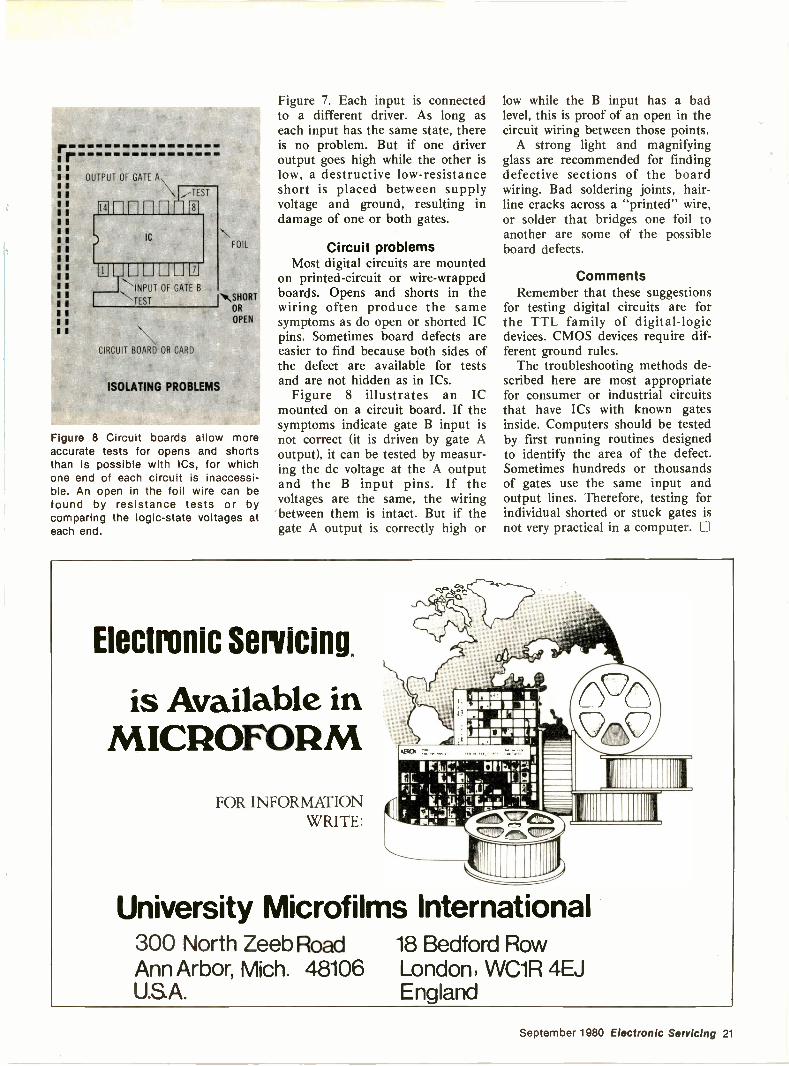
Figure 6 An internal short from the A input IC pin and the internal B +can produce a huge current when the driving gate attempts to deliveroutput. If the short is between the A input pin and ground, nothing
powera lowwould
overload until the previous gate tries to deliver a high. Both defects usually ruinthe driving gate.
6, where a following NAND has aninternal short from the A -input pinto the supply voltage. When thefirst NAND develops a high output,the condition is correct because theshort in the second gate places apermanent high at the affectedinput. The only symptom is thehigh that has a higher voltage.
A serious problem begins whenthe preceding NAND attempts tooutput a low. Q4 in the first NANDis saturation -biased into a virtualshort circuit that conducts a hugecurrent from the B+ power supplythrough the defective secondNAND. Instantaneous and catas-trophic failure of the driving gateusually results. Of course, thesecond gate was already bad.
When the A input pin of thesecond NAND is shorted to ground,the situation is similar but theeffects are reversed. A low from thedriving gate has no adverse effect,but when the output attempts to gohigh, Q3 is fully conducting to forma dead short between the first -gateB+ pin and ground. Q3 is ruinedimmediately.
Shorted output pins of gatesmight present different symptoms.A short at the pin usually ruins theoutput stage, exactly as though thenext stage input was shorted.However, after the output stagefails, the output pin can have apermanent high or low.
It is difficult to predict theresults of other pin -to -pin shorts.Sometimes the stage oscillates, andpossibly damages the driving IC.
A short between two input pinsof a three -input NAND is shown in
B
C
SHORTNAND
INTERNALLY SHORTED INPUTS
Figure 7 The result of an internal shortthat connects two input pins isdifficult to forecast. Because eachinput comes from a different drivinggate, a severe short occurs when theinputs attempt to receive oppositestates.
20 Electronic Servicing September 1980
rr
1 OUTPUT OF GATE A
1
a
1
1
aa
a
aa
aa
a
a
INPUT OF GATE B
'JEST
CIRCUIT BOARD OR CARD
ISOLATING PROBLEMS
FOIL
NNSHORTOR
OPEN
Figure 8 Circuit boards allow moreaccurate tests for opens and shortsthan is possible with ICs, for whichone end of each circuit is inaccessi-ble. An open in the foil wire can befound by resistance tests or bycomparing the logic -state voltages ateach end.
Figure 7. Each input is connectedto a different driver. As long aseach input has the same state, thereis no problem. But if one driveroutput goes high while the other islow, a destructive low -resistanceshort is placed between supplyvoltage and ground, resulting indamage of one or both gates.
Circuit problemsMost digital circuits are mounted
on printed -circuit or wire -wrappedboards. Opens and shorts in thewiring often produce the samesymptoms as do open or shorted ICpins. Sometimes board defects areeasier to find because both sides ofthe defect are available for testsand are not hidden as in ICs.
Figure 8 illustrates an ICmounted on a circuit board. If thesymptoms indicate gate B input isnot correct (it is driven by gate Aoutput), it can be tested by measur-ing the dc voltage at the A outputand the B input pins. If thevoltages are the same, the wiringbetween them is intact. But if thegate A output is correctly high or
low while the B input has a badlevel, this is proof of an open in thecircuit wiring between those points.
A strong light and magnifyingglass are recommended for findingdefective sections of the boardwiring. Bad soldering joints, hair-line cracks across a "printed" wire,or solder that bridges one foil toanother are some of the possibleboard defects.
CommentsRemember that these suggestions
for testing digital circuits are forthe TTL family of digital -logicdevices. CMOS devices require dif-ferent ground rules.
The troubleshooting methods de-scribed here are most appropriatefor consumer or industrial circuitsthat have ICs with known gatesinside. Computers should be testedby first running routines designedto identify the area of the defect.Sometimes hundreds or thousandsof gates use the same input andoutput lines. Therefore, testing forindividual shorted or stuck gates is
practical in a computer. El
Electronic Servicing.
is Available inMICROFORM
FOR INFORMATIONWRITE:
I r.LE!- 140
Its 3ILI
fir FLO lir6167.31.
University Microfilms International300 North Zeeb Road 18 Bedford RowAnn Arbor, Mich. 48106 London, WC1R 4EJU.S.A. England
September 1980 Electronic Servicing 21
Consumer Servicing
2
RCA CTC99verticalsweep
This last installment of the RCA CTC99 and CTC101 seriescontinues the circuit -operation information and provides manypictures from the TV screen and matching scope waveforms fortypical parts failures.
22 Electronic Servicing September 1980
By Gill Grieshaber, CETGill's Color TV
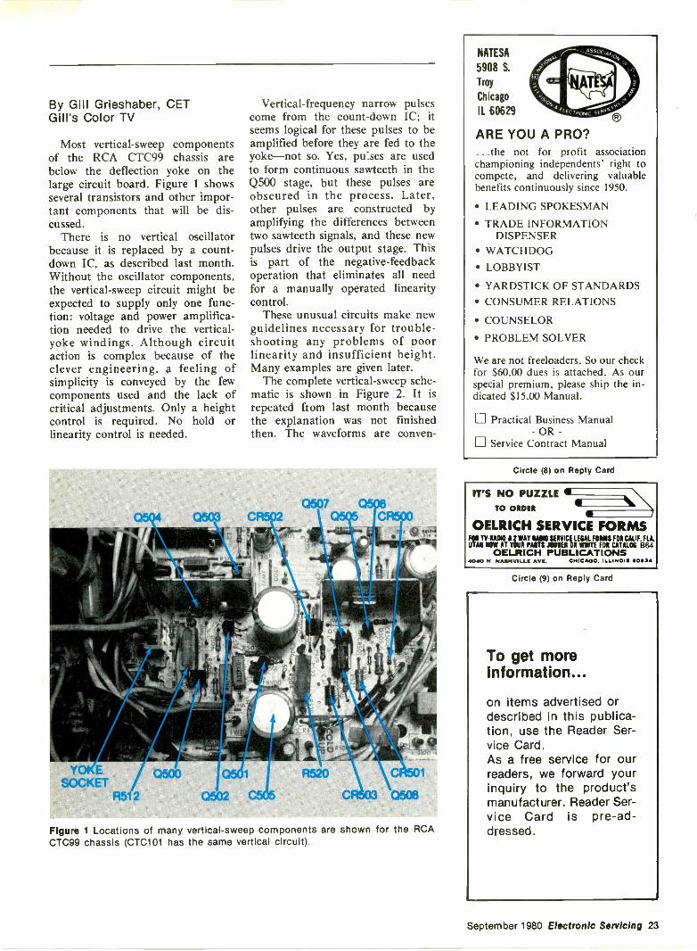
Most vertical -sweep componentsof the RCA CTC99 chassis arebelow the deflection yoke on thelarge circuit board. Figure 1 showsseveral transistors and other impor-tant components that will be dis-cussed.
There is no vertical oscillatorbecause it is replaced by a count-down IC, as described last month.Without the oscillator components,the vertical -sweep circuit might beexpected to supply only one func-tion: voltage and power amplifica-tion needed to drive the vertical -yoke windings. Although circuitaction is complex because of theclever engineering, a feeling ofsimplicity is conveyed by the fewcomponents used and the lack ofcritical adjustments. Only a heightcontrol is required. No hold orlinearity control is needed.
Vertical -frequency narrow pulsescome from the count -down IC; itseems logical for these pulses to beamplified before they are fed to theyoke-not so. Yes, pulses are usedto form continuous sawteeth in theQ500 stage, but these pulses areobscured in the process. Later,other pulses are constructed byamplifying the differences betweentwo sawteeth signals, and these newpulses drive the output stage. Thisis part of the negative -feedbackoperation that eliminates all needfor a manually operated linearitycontrol.
These unusual circuits make newguidelines necessary for trouble-shooting any problems of poorlinearity and insufficient height.Many examples are given later.
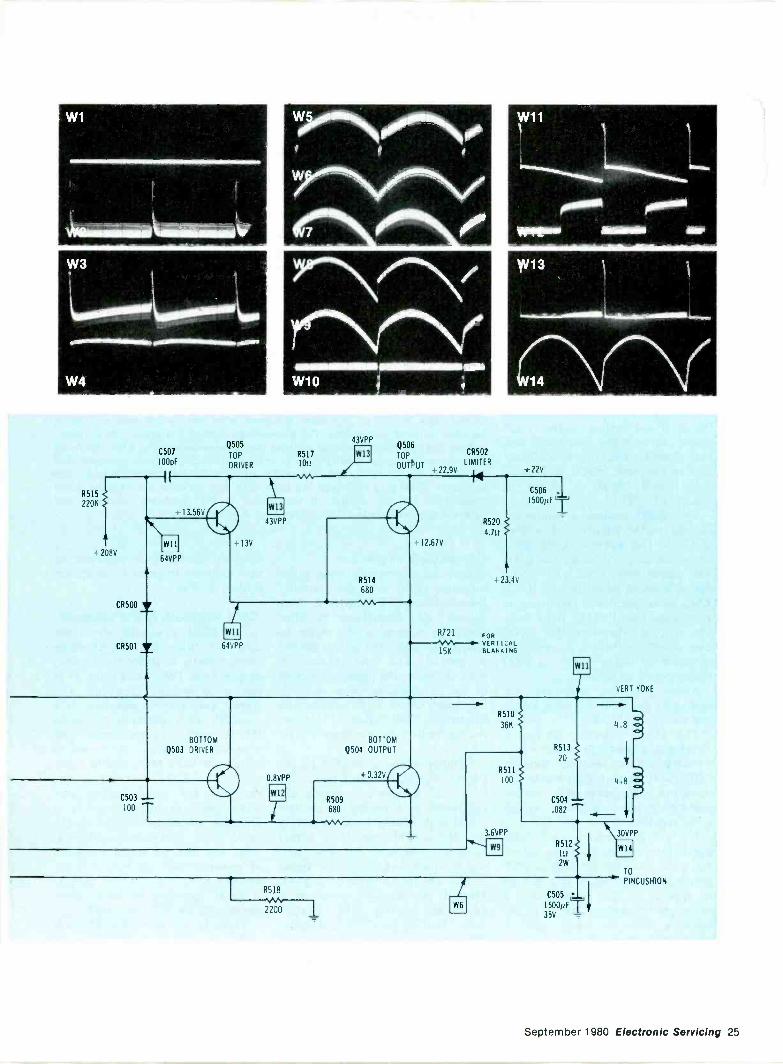
The complete vertical -sweep sche-matic is shown in Figure 2. It isrepeated from last month becausethe explanation was not finishedthen. The waveforms are conven-
Figure 1 Locations of many vertical -sweep components are shown for the RCACTC99 chassis (CTC101 has the same vertical circuit).
NATESA
5908 S.
Troy
Chicago
IL 60629
ARE YOU A PRO?...the not for profit associationchampioning independents' right tocompete, and delivering valuablebenefits continuously since 1950.
LEADING SPOKESMAN
TRADE INFORMATIONDISPENSER
WATCHDOG LOBBYIST
YARDSTICK OF STANDARDS CONSUMER RELATIONS
COUNSELOR
PROBLEM SOLVER
We are not freeloaders. So our checkfor $60.00 dues is attached. As ourspecial premium, please ship the in-dicated $15.00 Manual.
Practical Business Manual- OR
Service Contract Manual
Circle (8) on Reply Card
IT'S NO PUZZLETO ORDER
OELRICH SERVICE FORMSFOR TY-RA010 i 2 WAY RA010 SERVICE LEGAL FORMS FOR CALIF. FLA.UTAH NOW AT YOUR ARTS JOBBER OR WRITE FOR CATALOG B64
OELRICH PUBLICATIONS4040 N. NASHVILLE AVE. CHICAGO. ILLINOIS 60634
Circle (9) on Reply Card
To get moreinformation...
on items advertised ordescribed in this publica-tion, use the Reader Ser-vice Card.As a free service for ourreaders, we forward yourinquiry to the product'smanufacturer. Reader Ser-vice Card is pre -ad-dressed.
September 1980 Electronic Servicing 23
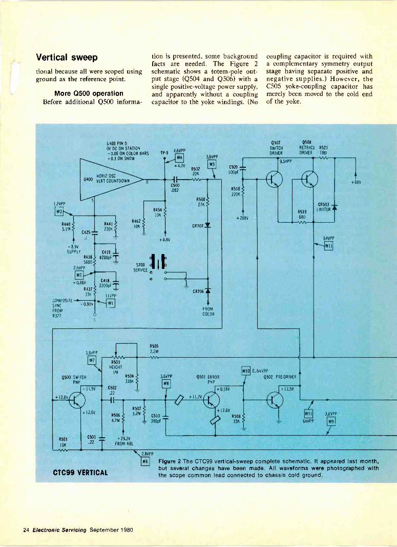
Vertical sweeptional because all were scoped usingground as the reference point.
More 0500 operationBefore additional Q500 informa-
tion is presented, some backgroundfacts are needed. The Figure 2schematic shows a totem -pole out-put stage (Q504 and Q506) with asingle positive -voltage power supply,and apparently without a couplingcapacitor to the yoke windings. (No
coupling capacitor is required witha complementary symmetry outputstage having separate positive andnegative supplies.) However, theC505 yoke -coupling capacitor hasmerely been moved to the cold endof the yoke.
1.2VPP
R440
5.1M
-89VSUPPLY C419
R438 8200pFT5600
2.5VPP
C425
U400 PIN 5OV DC ON STATION
-0.06 ON COLOR BARS+0.3 ON SNOW
COMPOSITE
SYNC
FROM
R327
- 0.96V
R437
336
+ 0.98V
C4I8.22008F T
I VPP
R462
10K
TP-94.6VPP
+4.20R50220K
C500.082
R454
S700
SERVICE
0
10K
R500
27K
CR707
+ 8 9V
3.6VPP
1--W7
CR706
FROM
COLOR
3.6VPP
W7
Q500 SWITCHPNP
I2.6V
R501
10K
N/40V
11.9V
+ 12.6V
C501
R505
2.2 M
R503HEIGHT
1MR504
3306
C502
.22
Q507
SWITCH
DRIVER
Q508
RETRACE R521
DRIVER 1011
C509
100pF
R516
220K
+ 208V
9.5VPP
R519
680
CR503
LIMITER AL
64VPP64VPF'
+60V
3.6VPP
.22 T
R506
4.7M
R507
3.3 M
+ 29.2V
FROM ABL
C510--390pF
Q501 ERROR
PNP
+ 11.2V
W10
+ 0.580
+ 12.6V
R508
33K
0.64VPP
Q502 PRE -DRIVER
+ I2.5V
64VPP
3.6VPP
CTC99 VERTICAL
\LEPPW6 Figure 2 The CTC99 vertical -sweep complete schematic. It appeared last month,
but several changes have been made. All waveforms were photographed withthe scope common lead connected to chassis cold ground.
24 Electronic Servicing September 1980
C507
100pF
Q505
TOP
DRIVER
11111111111111111111111111111111111111111111111111111111111,11111111111
W10
R5171011
43VPP
W13Q506
TOP
OUTPUT +22.9V
CR502
LIMITERt 22V
R515
2206
-208v
CR500
CR501
+ 13.56VW13
43VPP
+13V
R520
4.111
12.67V
+ 23.4V
R721 FOR
C506
1500pF T
WII
64VPP
rWII
64VPPX
A
R514
680
VERTICAL15K BLANKING
R5I0
36K
BOTTOM BOTTOM
Q503 DRIVER Q504 OUTPUT R513
20
0 8VPP + 0.32VR511
100
C503
100
IT R509680
W12C504
.082
3.6VPP
W91
R518
2200W6
wn
VERT YOKE
-R512
111
2W
4.8
4.8
30VPP
W14
TO
PINCUSHION
C505
I500µFT35V =
September 1980 Electronic Servicing 25
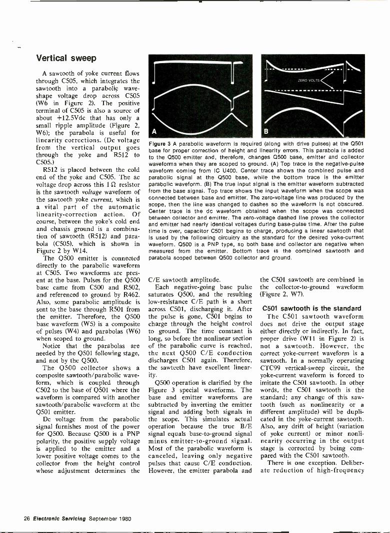
Vertical sweep
A sawtooth of yoke current flowsthrough C505, which integrates thesawtooth into a parabolic wave -shape voltage drop across C505(W6 in Figure 2). The positiveterminal of C505 is also a source ofabout +12.5Vdc that has only asmall ripple amplitude (Figure 2,W6); the parabola is useful forlinearity corrections. (Dc voltagefrom the vertical output goesthrough the yoke and 8512 toC505.)
R512 is placed between the coldend of the yoke and C505. The acvoltage drop across this 1Q resistoris the sawtooth voltage waveform ofthe sawtooth yoke current, which isa vital part of the automaticlinearity -correction action. Ofcourse, between the yoke's cold endand chassis ground is a combina-tion of sawtooth (R512) and para-bola (C505), which is shown inFigure 2 by W14.
The Q500 emitter is connecteddirectly to the parabolic waveformat C505. Two waveforms are pres-ent at the base. Pulses for the Q500base came from C500 and R502,and referenced to ground by R462.Also, some parabolic amplitude issent to the base through R501 fromthe emitter. Therefore, the Q500base waveform (W5) is a compositeof pulses (W4) and parabolas (W6)when scoped to ground.
Notice that the parabolas areneeded by the Q501 following stage,and not by the Q500.
The Q500 collector shows acomposite sawtooth/parabolic wave-form, which is coupled throughC502 to the base of Q501 where thewaveform is compared with anothersawtooth/parabolic waveform at theQ501 emitter.
Dc voltage from the parabolicsignal furnishes most of the powerfor Q500. Because Q500 is a PNPpolarity, the positive supply voltageis applied to the emitter and alower positive voltage comes to thecollector from the height controlwhose adjustment determines the
ELIO VOL iS
Figure 3 A parabolic waveform is required (along with drive pulses) at the 0501base for proper correction of height and linearity errors. This parabola is addedto the Q500 emitter and, therefore, changes Q500 base, emitter and collectorwaveforms when they are scoped to ground. (A) Top trace is the negative -pulsewaveform coming from IC U400. Center trace shows the combined pulse andparabolic signal at the Q500 base, while the bottom trace is the emitterparabolic waveform. (B) The true input signal is the emitter waveform subtractedfrom the base signal. Top trace shows the input waveform when the scope wasconnected between base and emitter. The zero -voltage line was produced by thescope, then the line was changed to dashes so the waveform is not obscured.Center trace is the dc waveform obtained when the scope was connectedbetween collector and emitter. The zero -voltage dashed line proves the collectorand emitter had nearly identical voltages during base -pulse time. After the pulsetime is over, capacitor C501 begins to charge, producing a linear sawtooth thatis used by the following circuitry as the standard for the desired yoke -currentwaveform. Q500 is a PNP type, so both base and collector are negative whenmeasured from the emitter. Bottom trace is the combined sawtooth andparabola scoped between Q500 collector and ground.
C/E sawtooth amplitude.Each negative -going base pulse
saturates Q500, and the resultinglow -resistance C/E path is a shortacross C501, discharging it. Afterthe pulse is gone, C501 begins tocharge through the height controlto ground. The time constant islong, so before the nonlinear sectionof the parabolic curve is reached,the next Q500 C/E conductiondischarges C501 again. Therefore,the sawteeth have excellent linear-ity.
Q500 operation is clarified by theFigure 3 special waveforms. Thebase and emitter waveforms aresubtracted by inverting the emittersignal and adding both signals inthe scope. This simulates actualoperation because the true B/Esignal equals base -to -ground signalminus emitter -to -ground signal.Most of the parabolic waveform iscanceled, leaving only negativepulses that cause C/E conduction.However, the emitter parabola and
the C501 sawtooth are combined inthe collector -to -ground waveform(Figure 2, W7).
C501 sawtooth is the standardThe C501 sawtooth waveform
does not drive the output stageeither directly or indirectly. In fact,proper drive (W11 in Figure 2) isnot a sawtooth. However, thecorrect yoke -current waveform is asawtooth. In a normally operatingCTC99 vertical -sweep circuit, theyoke -current waveform is forced toimitate the C501 sawtooth. In otherwords, the C501 sawtooth is thestandard; any change of this saw -tooth (such as nonlinearity or adifferent amplitude) will be dupli-cated in the yoke -current sawtooth.Also, any drift of height (variationof yoke current) or minor nonli-nearity occurring in the outputstage is corrected by being com-pared with the C501 sawtooth.
There is one exception. Deliber-ate reduction of high -frequency
26 Electronic Servicing September 1980
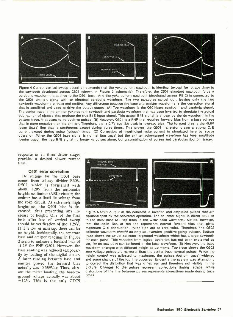
ZERO VOLTS
B+0.7V
REVERSE BI;N1h,
ZERO
FORWARD BIAS-0.6V
A IBM
Figure 4 Correct vertical -sweep operation demands that the yoke -current sawtooth is identical (except for retrace time) tothe sawtooth developed across C501 (shown in Figure 2 schematic). Therefore, the C501 standard sawtooth (plus aparabolic waveform) is applied to the 0501 base. And the yoke -current sawtooth (developed across R512) is connected tothe Q501 emitter, along with an identical parabolic waveform. The two parabolas cancel out, leaving only the twosawtooth waveforms at base and emitter. Any difference between the base and emitter waveforms is the correction signalthat is amplified and used to drive the output stages. (A) Top waveform is the 0501 -base sawtooth and parabola signal.The center trace is the emitter yoke -current sawtooth and parabola waveform that has been inverted to simulate the actualsubtraction of signals that produce the true B/E input signal. This actual B/E signal is shown by the dc waveform In thebottom trace. It appears to be positive pulses. (B) However, 0501 is a PNP that requires forward bias from a base voltagethat is more negative than the emitter. Therefore, the + 0.7V positive peak is reversed bias. The forward bias Is the -0.6Vlower (base) line that is continuous except during pulse times. This proves the 0501 transistor draws a strong CIEcurrent except during pulse (retrace) times. (C) Correction of insufficient yoke current is simulated here by scopeoperation. When the 0501 base signal is normal (top trace) but the emitter yoke -current waveform has less amplitude(center trace), the true B/E signal no longer is pulses alone, but a combination of pulses and parabolas (bottom trace).
response in all three driver stagesprovides a desired slower retracetime.
0501 error correctionDc voltage for the Q501 base
comes from voltage divider R506 -R507, which is furnished withabout +29V from the automaticbrightness -limiter (ABL) circuit; theemitter has a fixed de voltage fromthe yoke circuit. At extremely highbrightness, the Q501 bias is de-creased, thus preventing any in-crease of height. One of the firsttests after loss of vertical sweepshould be verification of the +29V.If it is low or missing, there can beno height. Incidentally, the separatebase and emitter readings in Figure2 seem to indicate a forward bias of-1.2V for PNP Q501. However, thebase reading was reduced temporar-ily by loading of the digital meter.A later reading between base andemitter proved the forward biasactually was -0.559Vdc. Thus, with-out the meter loading, the base -to -ground voltage actually was about+12V. This is the only CTC9
A FORWARD BIAS+0 64VDC
ZERO VOL TS
ZERO VOLTS
111111111,
U
B
J 11Figure 5 Q501 output at the collector is inverted and amplified pulses that aresquare -tipped by the saturated operation. The collector signal is direct coupledto the 8502 base (A) Top trace is the Q502 base waveform. Notice, however,that the solid line at the top represents normal forward bias that givesmaximum C/E conduction. Pulse tips are at zero volts. Therefore, the 0502collector waveform should be only an inversion (positive -going pulses). Bottomtrace shows the actual collector -to -ground waveform which has a large sawtoothfor each pulse. This variation from logical operation has not been explained asyet, for no sawtooth can be found in the base waveform. (B) However, the basewaveform changes with different height adjustments. Top trace shows the 0502zero -voltage pulses are narrower than the center -trace normal pulses. When theheight control was adjusted to maximum, the pulses (bottom trace) widenedand some change of the top line occurred. Evidently the system was attemptingto correct the distortion that was off -screen and therefore not visible in thepicture. Changes to the pulses represent corrections during retrace, whiledistortions of the line between pulses represents corrections made during tracetimes.
September 1980 Electronic Servicing 27
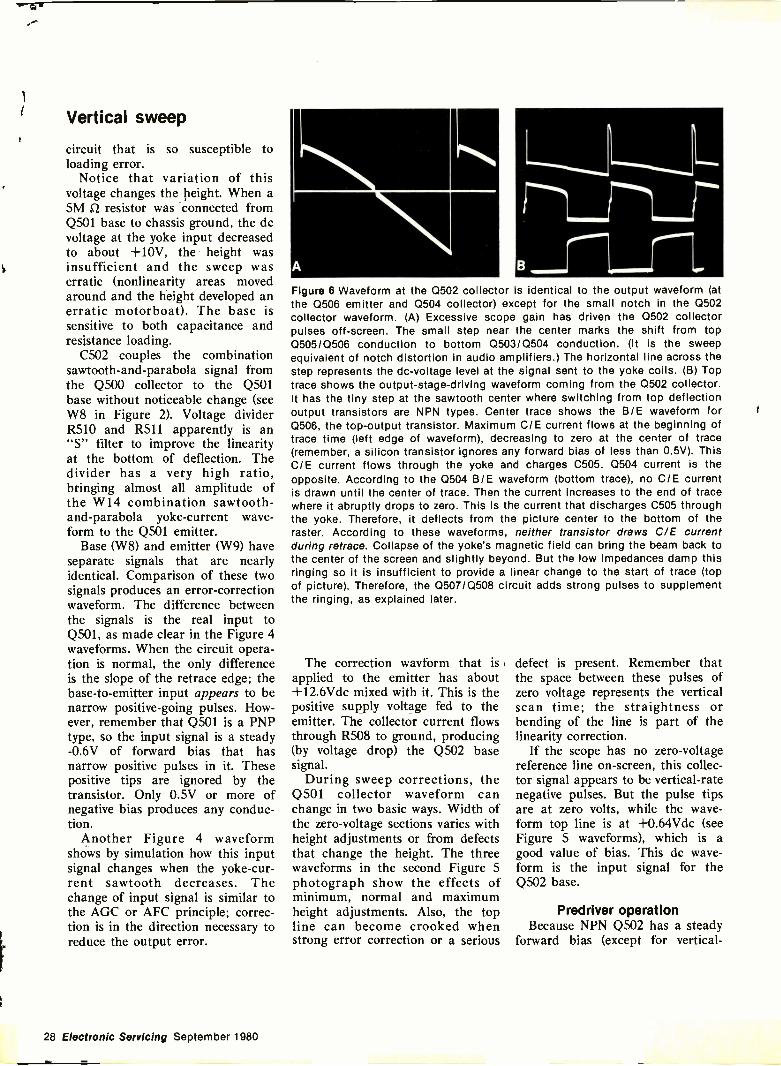
Vertical sweep
circuit that is so susceptible toloading error.
Notice that variation of thisvoltage changes the height. When a5M 2 resistor was connected fromQ501 base to chassis ground, the dcvoltage at the yoke input decreasedto about +10V, the height wasinsufficient and the sweep waserratic (nonlinearity areas movedaround and the height developed anerratic motorboat). The base issensitive to both capacitance andresistance loading.
C502 couples the combinationsawtooth-and-parabola signal fromthe Q500 collector to the Q501base without noticeable change (seeW8 in Figure 2). Voltage dividerR510 and R511 apparently is an"S" filter to improve the linearityat the bottom of deflection. Thedivider has a very high ratio,bringing almost all amplitude ofthe W14 combination sawtooth-and-parabola yoke -current wave-form to the Q501 emitter.
Base (W8) and emitter (W9) haveseparate signals that are nearlyidentical. Comparison of these twosignals produces an error -correctionwaveform. The difference betweenthe signals is the real input toQ501, as made clear in the Figure 4waveforms. When the circuit opera-tion is normal, the only differenceis the slope of the retrace edge; thebase -to -emitter input appears to benarrow positive -going pulses. How-ever, remember that Q501 is a PNPtype, so the input signal is a steady-0.6V of forward bias that hasnarrow positive pulses in it. Thesepositive tips are ignored by thetransistor. Only 0.5V or more ofnegative bias produces any conduc-tion.
Another Figure 4 waveformshows by simulation how this inputsignal changes when the yoke -cur-rent sawtooth decreases. Thechange of input signal is similar tothe AGC or AFC principle; correc-tion is in the direction necessary toreduce the output error.
B
#0,0000".
.1=1110
Figure 6 Waveform at the Q502 collector is identical to the output waveform (atthe 0506 emitter and Q504 collector) except for the small notch in the Q502collector waveform. (A) Excessive scope gain has driven the 0502 collectorpulses off -screen. The small step near the center marks the shift from top0505/Q506 conduction to bottom 0503/Q504 conduction. (It is the sweepequivalent of notch distortion in audio amplifiers.) The horizontal line across thestep represents the dc -voltage level at the signal sent to the yoke coils. (B) Toptrace shows the output -stage -driving waveform coming from the Q502 collector.It has the tiny step at the sawtooth center where switching from top deflectionoutput transistors are NPN types. Center trace shows the B/E waveform forQ506, the top -output transistor. Maximum C/E current flows at the beginning oftrace time (left edge of waveform), decreasing to zero at the center of trace(remember, a silicon transistor ignores any forward bias of less than 0.5V). ThisC/E current flows through the yoke and charges C505. Q504 current is theopposite. According to the Q504 B/E waveform (bottom trace), no CIE currentis drawn until the center of trace. Then the current increases to the end of tracewhere it abruptly drops to zero. This is the current that discharges C505 throughthe yoke. Therefore, it deflects from the picture center to the bottom of theraster. According to these waveforms, neither transistor draws C/E currentduring retrace. Collapse of the yoke's magnetic field can bring the beam back tothe center of the screen and slightly beyond. But the low impedances damp thisringing so it is insufficient to provide a linear change to the start of trace (topof picture). Therefore, the 0507/0508 circuit adds strong pulses to supplementthe ringing, as explained later.
The correction wavform that is r
applied to the emitter has about+12.6Vdc mixed with it. This is thepositive supply voltage fed to theemitter. The collector current flowsthrough R508 to ground, producing(by voltage drop) the Q502 basesignal.
During sweep corrections, theQ501 collector waveform canchange in two basic ways. Width ofthe zero -voltage sections varies withheight adjustments or from defectsthat change the height. The threewaveforms in the second Figure 5photograph show the effects ofminimum, normal and maximumheight adjustments. Also, the topline can become crooked whenstrong error correction or a serious
defect is present. Remember thatthe space between these pulses ofzero voltage represents the verticalscan time; the straightness orbending of the line is part of thelinearity correction.
If the scope has no zero -voltagereference line on -screen, this collec-tor signal appears to be vertical -ratenegative pulses. But the pulse tipsare at zero volts, while the wave-form top line is at +0.64Vdc (seeFigure 5 waveforms), which is agood value of bias. This dc wave-form is the input signal for theQ502 base.
Predriver operationBecause NPN Q502 has a steady
forward bias (except for vertical -
28 Electronic Sevicing September 1980
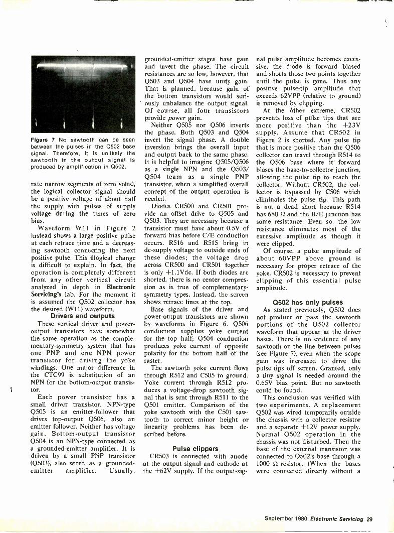
pervesp,
Figure 7 No sawtooth can be seenbetween the pulses in the Q502 basesignal. Therefore, it is unlikely thesawtooth in the output signal isproduced by amplification in Q502.
rate narrow segments of zero volts),the logical collector signal shouldbe a positive voltage of about halfthe supply with pulses of supplyvoltage during the times of zerobias.
Waveform W11 in Figure 2instead shows a large positive pulseat each retrace time and a decreas-ing sawtooth connecting the nextpositive pulse. This illogical changeis difficult to explain. In fact, theoperation is completely differentfrom any other vertical circuitanalyzed in depth in ElectronicServicing's lab. For the moment itis assumed the Q502 collector hasthe desired (W11) waveform.
Drivers and outputsThese vertical driver and power -
output transistors have somewhatthe same operation as the comple-mentary -symmetry system that hasone PNP and one NPN powertransistor for driving the yokewindings. One major difference inthe CTC99 is substitution of anNPN for the bottom -output transis-tor.
Each power transistor has asmall driver transistor. NPN-typeQ505 is an emitter -follower thatdrives top -output Q506, also anemitter follower. Neither has voltagegain. Bottom -output transistorQ504 is an NPN-type connected asa grounded -emitter amplifier. It isdriven by a small PNP transistor(Q503), also wired as a grounded -emitter amplifier. Usually,
grounded -emitter stages have gainand invert the phase. The circuitresistances are so low, however, thatQ503 and Q504 have unity gain.That is planned, because gain ofthe bottom transistors would seri-ously unbalance the output signal.Of course, all four transistorsprovide power gain.
Neither Q505 nor Q506 invertsthe phase. Both Q503 and Q504invert the signal phase. A doubleinversion brings the overall inputand output back to the same phase.It is helpful to imagine Q505/Q506as a single NPN and the Q503/Q504 team as a single PNPtransistor, when a simplified overallconcept of the output operation isneeded.
Diodes CR500 and CR501 pro-vide an offset drive to Q505 and0503. They are necessary because atransistor must have about 0.5V offorward bias before C/E conductionoccurs. R516 and R515 bring indc -supply voltage to outside ends ofthese diodes; the voltage dropacross CR500 and CR501 togetheris only +1.1Vdc. If both diodes areshorted, there is no center compres-sion as is true of complementary -symmetry types. Instead, the screenshows retrace lines at the top.
Base signals of the driver andpower -output transistors are shownby waveforms in Figure 6. Q506conduction supplies yoke currentfor the top half; Q504 conductionproduces yoke current of oppositepolarity for the bottom half of theraster.
The sawtooth yoke current flowsthrough R512 and C505 to ground.Yoke current through R512 pro-duces a voltage -drop sawtooth sig-nal that is sent through R511 to theQ501 emitter. Comparison of theyoke sawtooth with the C501 saw -tooth to correct minor height orlinearity problems has been de-scribed before.
Pulse clippersCR503 is connected with anode
at the output signal and cathode atthe +62V supply. If the output -sig-
nal pulse amplitude becomes exces-sive, the diode is forward biasedand shorts those two points togetheruntil the pulse is gone. Thus anypositive pulse -tip amplitude thatexceeds 62VPP (relative to ground)is removed by clipping.
At the other extreme, CR502prevents loss of pulse tips that aremore positive than the +23Vsupply. Assume that CR502 inFigure 2 is shorted. Any pulse tipthat is more positive than the Q506collector can travel through R514 tothe Q506 base where it' forwardbiases the base -to -collector junction,allowing the pulse tip to reach thecollector. Without CR502, the col-lector is bypassed by C506 whicheliminates the pulse tip. This pathis not a dead short because R514has 680 n and the B/E junction hassome resistance. Even so, the lowresistance eliminates most of theexcessive amplitude as though itwere clipped.
Of course, a pulse amplitude ofabout 60VPP above ground isnecessary for proper retrace of theyoke. CR502 is necessary to preventclipping of this essential pulseamplitude.
0502 has only pulsesAs stated previously, Q502 does
not produce or pass the sawtoothportions of the Q502 collectorwaveform that appear at the driverbases. There is no evidence of anysawtooth on the line between pulses(see Figure 7), even when the scopegain was increased to drive thepulse tips off screen. Granted, onlya tiny signal is needed around the0.65V bias point. But no sawtoothcould be found.
This conclusion was verified withtwo experiments. A replacementQ502 was wired temporarily outsidethe chassis with a collector resistorand a separate +12V power supply.Normal Q502 operation in thechassis was not disturbed. Then thebase of the external transistor wasconnected to Q502's base through a1000 O. resistor. (When the baseswere connected directly without a
September 1980 Electronic Servicing 29
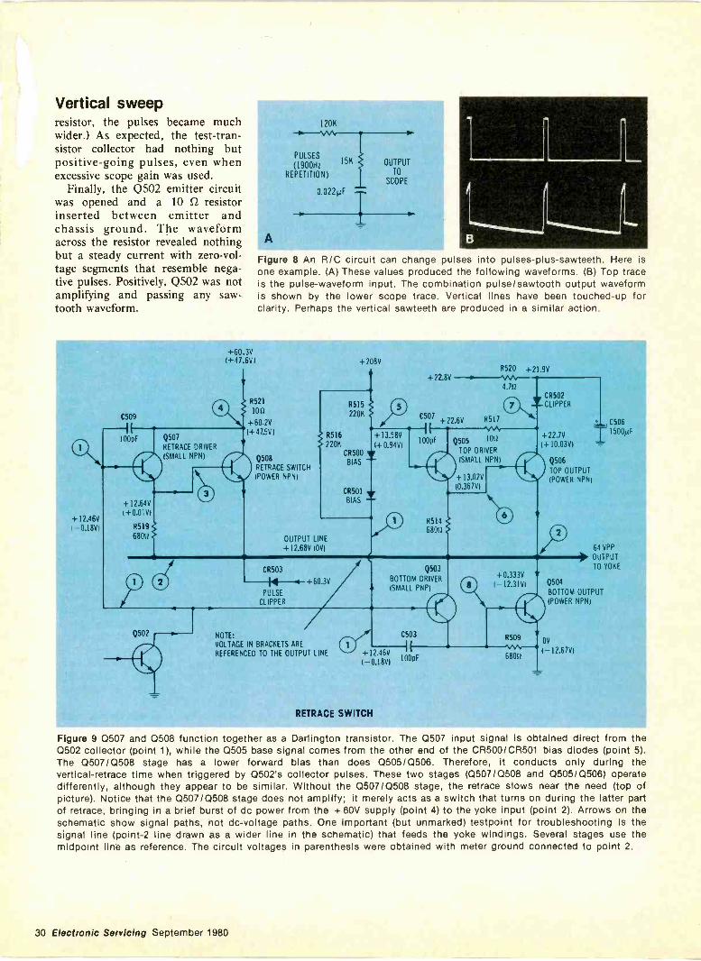
Vertical sweepresistor, the pulses became muchwider.) As expected, the test -tran-sistor collector had nothing butpositive -going pulses, even whenexcessive scope gain was used.
Finally, the Q502 emitter circuitwas opened and a 10 EZ resistorinserted between emitter andchassis ground. The waveformacross the resistor revealed nothingbut a steady current with zero -vol-tage segments that resemble nega-tive pulses. Positively, Q502 was notamplifying and passing any saw -tooth waveform.
120K
PULSES15K
(1900HzREPETITION)
0.022µF
OUTPUT
TO
SCOPE
A
Figure 8 An R/C circuit can change pulses into pulses-plus-sawteeth.one example. (A) These values produced the following waveforms. (B) Top traceis the pulse -waveform input. The combination pulselsawtooth output waveformis shown by the lower scope trace. Vertical lines have been touched -up forclarity. Perhaps the vertical sawteeth are produced in a similar action.
Here is
+ 12.46V(-0.181/1
+60 3V1+47.6V(
C509
100pF
+ 12.64V(+0.01V)
R5I9680u
Q502
Q507
RETRACE DRIVER
(SMALL NPNI
R521
lOn
+60.2V1+47.5V)
Q508RETRACE SWITCH
+208V
R515
220K
R516
220KCR500
BIAS
OUTPUT LINE+12.68V 10V)
CR503
/4 4PULSE
CLIPPER
+60.3V
NOTE:
VOLTAGE IN BRACKETS AREREFERENCED TO THE OUTPUT LINE
CR501
BIAS
+ 13.58V
(+0.94V)
R520 +21.9V+22.8V
C507+22.6V R5I7
4.7nmCCLRI5F0P2ER
100pF Q505 1011
TOP DRIVER
(SMALL NPNI
R514
6801
Q503
BOTTOM DRIVER
(SMALL PNPI
+12.46V100pF
I -0.18V1
C503
RETRACE SWITCH
+13.02V10.367V)
+22.7V(+10.03V)
© Q506TOP OUTPUT(POWER NPNI
+0.333V1-12.3101
I* C506
ii 1500µF
..=
64 VPP
)1, OUTPUTTO YOKE
Q504
BOTTOM OUTPUT
(POWER NPNI
R509OV
(-12.67V168011
Figure 9 Q507 and Q508 function together as a Darlington transistor. The Q507 input signal is obtained direct from theQ502 collector (point 1), while the Q505 base signal comes from the other end of the CR500/CR501 bias diodes (point 5).The Q507/Q508 stage has a lower forward bias than does Q505/Q506. Therefore, it conducts only during thevertical -retrace time when triggered by Q502's collector pulses. These two stages (Q507/Q508 and Q505/Q506) operatedifferently, although they appear to be similar. Without the Q507/Q508 stage, the retrace slows near the need (top ofpicture). Notice that the Q507/Q508 stage does not amplify; it merely acts as a switch that turns on during the latter partof retrace, bringing in a brief burst of dc power from the + 60V supply (point 4) to the yoke input (point 2). Arrows on theschematic show signal paths, not dc -voltage paths. One Important (but unmarked) testpoint for troubleshooting Is thesignal line (point -2 line drawn as a wider line In the schematic) that feeds the yoke windings. Several stages use themidpoint line as reference. The circuit voltages In parenthesis were obtained with meter ground connected to point 2.
30 Electronic Servicing September 1980
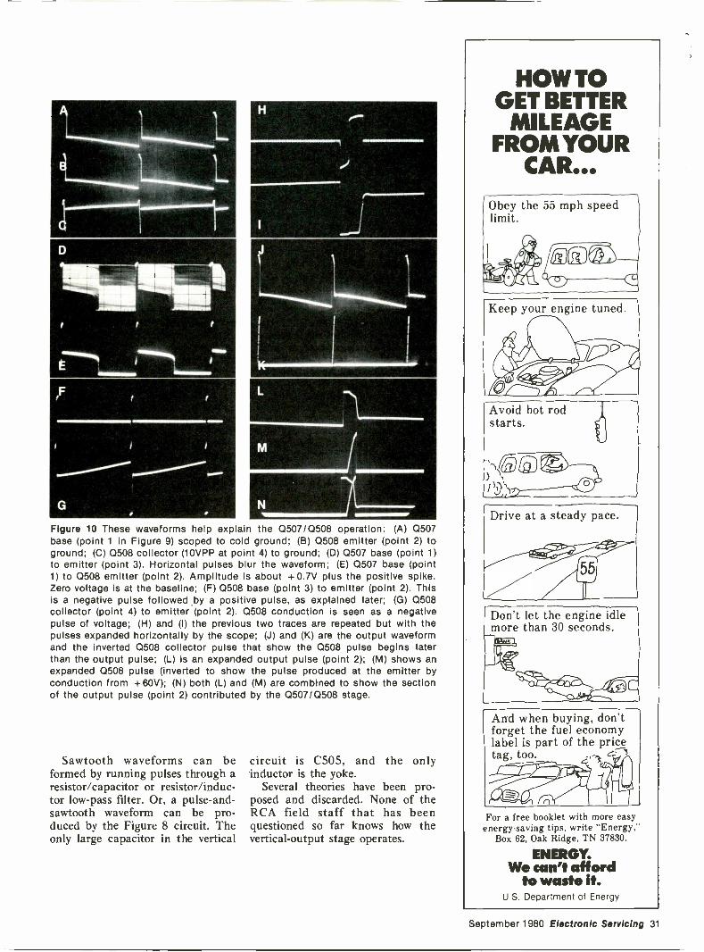
Figure 10 These waveforms help explain the Q507/Q508 operation: (A) Q507base (point 1 in Figure 9) scoped to cold ground; (B) Q508 emitter (point 2) toground; (C) Q508 collector (10VPP at point 4) to ground; (D) Q507 base (point 1)to emitter (point 3). Horizontal pulses blur the waveform; (E) Q507 base (point1) to Q508 emitter (point 2). Amplitude is about +0.7V plus the positive spike.Zero voltage is at the baseline; (F) Q508 base (point 3) to emitter (point 2). Thisis a negative pulse followed by a positive pulse, as explained later; (G) Q508collector (point 4) to emitter (point 2). Q508 conduction is seen as a negativepulse of voltage; (H) and (I) the previous two traces are repeated but with thepulses expanded horizontally by the scope; (J) and (K) are the output waveformand the inverted Q508 collector pulse that show the Q508 pulse begins laterthan the output pulse; (L) is an expanded output pulse (point 2); (M) shows anexpanded Q508 pulse (inverted to show the pulse produced at the emitter byconduction from +60V); (N) both (L) and (M) are combined to show the sectionof the output pulse (point 2) contributed by the Q507/Q508 stage.
Sawtooth waveforms can beformed by running pulses through aresistor/capacitor or resistor/induc-tor low-pass filter. Or, a pulse-and-sawtooth waveform can be pro-duced by the Figure 8 circuit. Theonly large capacitor in the vertical
circuit is C505, and the onlyinductor is the yoke.
Several theories have been pro-posed and discarded. None of theRCA field staff that has beenquestioned so far knows how thevertical -output stage operates.
HOW TOGET BETTER
MILEAGEFROM YOUR
CAR...
Obey the 55 mph speedlimit.
Keep your engine tuned. \
Avoid hot rodstarts.
)'Th.G7Mj3).1 4;ir
Drive at a steady pace.
5P
Don't let the engine idlemore than 30 seconds.
1.4.4,d41111r10 /402
And when buying, don'tforget the fuel economylabel is part of the pricetag, too.
For a free booklet with more easyenergy -saving tips, write "Energy,"
Box 62, Oak Ridge, TN 37830.
ENERGY.We can't afford
to waste it.U.S.Department of Energy
September 1980 Electronic Servicing 31
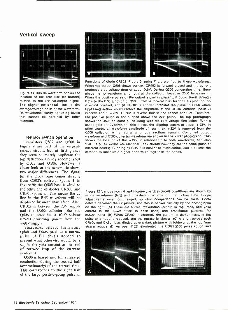
Vertical sweep
Figure 11 This dc waveform shows thelocation of the zero line (at bottom)relative to the vertical -output signal.The higher horizontal line is theaverage -voltage point of the waveform.Dc waveforms clarify operating levelsthat cannot be obtained by othermethods.
Retrace switch operationTransistors Q507 and Q508 in
Figure 9 are part of the vertical -retrace circuit, but at first glancethey seem to merely duplicate thetop deflection already accomplishedby Q505 and Q506. However, acloser look at the schematic showstwo major differences. The signalfor the Q507 base comes directlyfrom Q502's collector (point 1 inFigure 9); the Q505 base is wired tothe other end of diodes CR500 andCR501 (point 5). This means the dcline in the B/E waveform will bedisplaced by more than 1Vdc. Also,CR502 is between the 23V supplyand the Q506 collector. But theQ508 collecioi has a 10 SI resistor1l.11) piovidiiig power from the-rtiOV supply
1 ht;icfort acc ti a risistorsQSOS and Q5U6 pioduce a narrowpulse ut B+ that's needed toprevent what other wise would be asag in the yoke current at the endof retrace (top of the currentsawtooth).
Q508 is biased into full saturatedconduction during the second half(approximately) of the retrace time.This corresponds to the right halfof the large positive -going pulse in
11111111111111111111111111111111111111111
1111111111
11111111=11111111111111111111 111 111111
Functions of diode CR502 (Figure 9, point 7) are clarified by these waveforms.When top -output Q506 draws current, CR502 is forward biased and the currentproduces a dc -voltage drop of about 0.6V. During Q506 conduction time, therealmost is no waveform amplitude at the collector because C506 bypasses it.When the positive pulse of the output signal is present, it could travel throughR514 to the B/C junction of Q506 . This is forward bias for the B/C junction, soit would conduct, and (if CR502 is shorted) transfer the pulse to C506 wherebypassing action would remove the amplitude at the CR502 cathode (point 7)exceeds about +22V, CR502 is reverse biased and cannot conduct. Therefore,the positive pulse is not clipped above the 22V point. The top photographshows the Q506 collector pulse along with the zero -voltage line below. With ascope gain of 10V/division, this proves the clipping occurs at about +22V. Inother words, all waveform amplitude of less than +22V is removed from theQ506 collector, while higher amplitude sections remain. Combined outputwaveform and 0506 -collector waveform are shown in the lower photograph. Thisshows the location of the +22V in relationship to both waveforms, and alsothat the pulse widths are identical (they should be-they are the same pulse atdifferent points). Clipping by CR502 is similar to rectification, and it causes thecathode to measure a higher positive voltage than the anode.
Figure 12 Various normal and incorrect vertical -circuit conditions are shown byscope waveforms (left) and crosshatch patterns on the picture tube. Scopeadjustments were not changed, so valid comparisons can be made. Somedefects darkened the TV picture, and this is shown partially by the photographson the right. (A) These are nurrnal waveforms (output is top trace, and yokecurrent is the lower tiace in each case) and crosshatch patterns forcomparisons (B) When CR502 is shorted, the picture is darker because thepulse amplitude is reduced. and the retrace is slower (C) A short across bothCRbOu and CN5u1 bias diodes gave a dark picture with foldover at the top fromslower retrace tD) Ar. open R521 eliminated the 0507/Q508 pulse action and
smosummilm114111".agol-! . AMON1100. 1411111MOMWIN
' 111111.111gmb,l, AMMONOMMNIVICAliA,ORIONIMMMMOMOMMM4As400111110On11111M11IILId ;1_1,44141141.1111111MOOMMONWmAAMEMUMMIMOM1104041MMAIMMOMMUmMINIMOMANNIMOMMIMMMUMMINIMMONMEMMOMXMIME MENEMICOMM 1111
32 Electronic Servicing September 1980
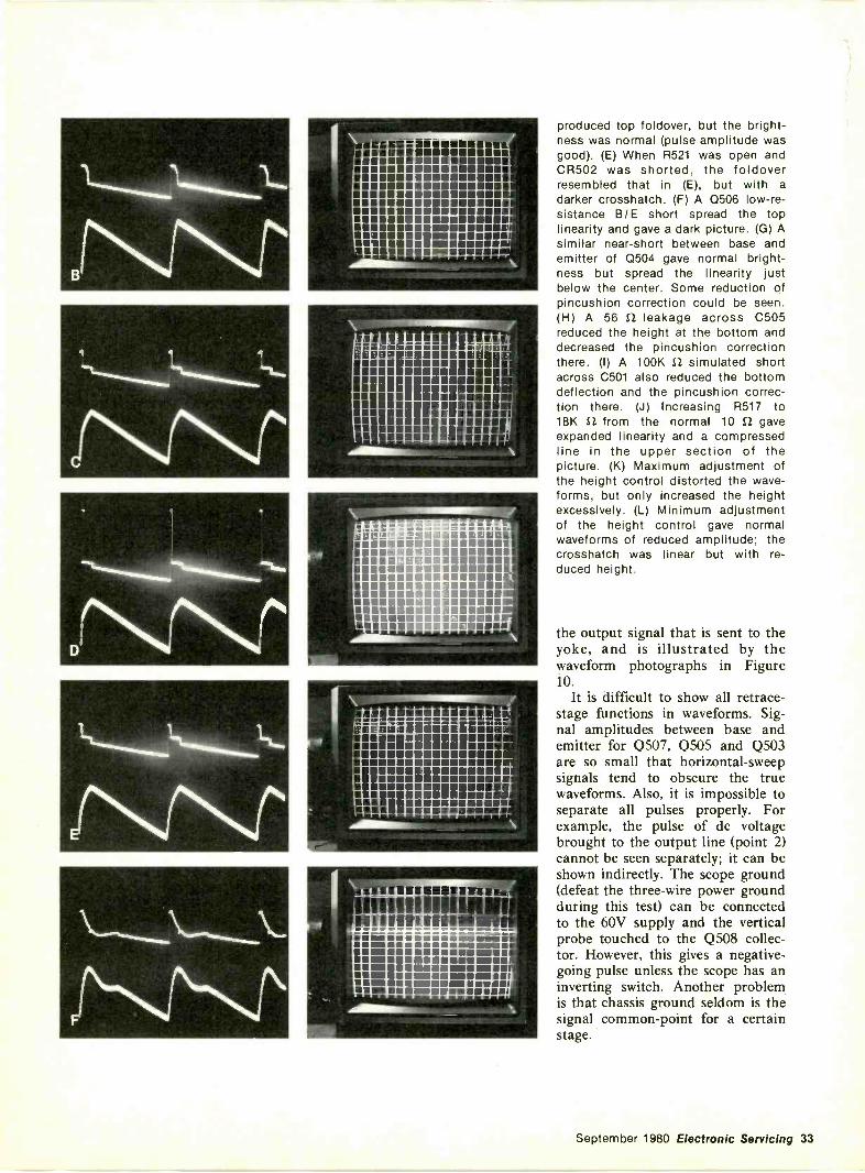
14%Nr'sS
..=-4q1 imisIsimmamounimIIIIMIIRM1111111111111MIn
111 111111111MIMMIMMIllMIIIIIIIIIIIIIMM111111111111111111.1111111111111111111W111111111111111111111111111111111M1111111111111111111111111111111111111111111111111111111M11111111
11111MintratininMIA11111111111111111111111mmiinumiimmin
MIMOMMOMMERISmamaciins ===== 11§14.111111NENUIPMIUMMIBI11111111111111111111WIMUMse NM1111111111111111111111111111111111M111
11111M1111111iNum Num immue 1miamsmammummismamssemmumilen
MUMMENSUMMUM
fifillOMMUMMOMMMESMOSWOONAMMIMINEMM
S OMMOOMOMMOIMMUMMEMMEMMIIMMINEMMEMMEMMEMOMOMMOMMENIOMMOMOSMOMMEMMOMMEMEMM11111111111111111.111111.111.1111111MROMMOMMEMWOMMEMMO1111.11111MOMMUOMMMOWNImalimMEMORMEmismomVIUMnimmommumwmOMM
N M IMO IIIMM=1Ile I
11111=11111111Mall in Nu am Oils amliiiillimissammewasoNam so alliesimmuummt
produced top foldover, but the bright-ness was normal (pulse amplitude wasgood). (E) When R521 was open andCR502 was shorted, the foldoverresembled that in (E), but with a
darker crosshatch. (F) A Q506 low -re-sistance B/E short spread the toplinearity and gave a dark picture. (G) Asimilar near -short between base andemitter of Q504 gave normal bright-ness but spread the linearity justbelow the center. Some reduction ofpincushion correction could be seen.(H) A 56 f2 leakage across C505reduced the height at the bottom anddecreased the pincushion correctionthere. (I) A 100K S2 simulated shortacross C501 also reduced the bottomdeflection and the pincushion correc-tion there. (J) Increasing R517 to18K S2 from the normal 10 2 gaveexpanded linearity and a compressedline in the upper section of thepicture. (K) Maximum adjustment ofthe height control distorted the wave-forms, but only increased the heightexcessively. (L) Minimum adjustmentof the height control gave normalwaveforms of reduced amplitude; thecrosshatch was linear but with re-duced height.
the output signal that is sent to theyoke, and is illustrated by thewaveform photographs in Figure10.
It is difficult to show all retrace -stage functions in waveforms. Sig-nal amplitudes between base andemitter for Q507, Q505 and Q503are so small that horizontal -sweepsignals tend to obscure the truewaveforms. Also, it is impossible toseparate all pulses properly. Forexample, the pulse of de voltagebrought to the output line (point 2)cannot be seen separately; it can beshown indirectly. The scope ground(defeat the three -wire power groundduring this test) can be connectedto the 60V supply and the verticalprobe touched to the Q508 collec-tor. However, this gives a negative -going pulse unless the scope has aninverting switch. Another problemis that chassis ground seldom is thesignal common -point for a certainstage.
September 1980 Electronic Servicing 33
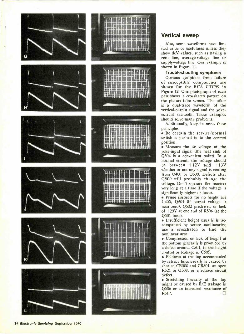
G
t 1 I
rNs.%1 h, o
1
; 1141414111100140444440040:1f444411\1141014040111,
.h4N1\-1\
L
mmonsommolimmnommismimmommammsimmommonnummummouMMOMOMMUMMOMMMOMMOO MMOMMVOIMOMOMMOMOMOOMOMMOMMOOMMOOMOIIMMOMERMIMMOOMMMO
ii.mmmmwwwwwwwmMMMOMMormeMOMMEMIOMMININIISMOMMOMMONSWMU MOMMOMMEMUMNIMIlig simummmimmitm al
UMWUMMOUVROOMOMMOMMimmesimmunominSMOUOUSIMSMEROMMOS UMEMOMUMMOSMOMOMEUOMMUUMOMMOOMMONMOMIMMOUWOOOMMINMOMONVOUNOROMMUSEMMIMameasommusimawminurmmommisemmummilmmitmmummoommusammawnium mailmommommansimm
cumin milmosumummmussommemosommummesupsomminummommemmmossommemommommemsammo MMMMMMMM mumIMO
I'llilRIPPPOMMIVII_immasersawaslitimilirmuslimensommommemmmemommemmissimirimmanamemamsommummomminommumummotsimmoommimmommewmsommemommummommemtsum smoommilimmir
Vertical sweepAlso, some waveforms have lim-
ited value or usefulness unless theyshow dcV values, such as having azero line, average -voltage line orsupply -voltage line. One example isshown in Figure 11.
Troubleshooting symptomsObvious symptoms from failure
of susceptible components areshown for the RCA CTC99 inFigure 12. One photograph of eachpair shows a crosshatch pattern onthe picture -tube screen. The otheris a dual -trace waveform of thevertical -output signal and the yoke -current sawtooth. These examplesshould solve many problems.
Additionally, keep in mind theseprinciples: Be certain the service/normalswitch is pushed in to the normalposition. Measure the dc voltage at theyoke -input signal (the heat sink ofQ504 is a convenient point). In anormal circuit, the voltage shouldbe between +12V and +13Vwhether or not any signal is comingfrom 0400 or Q500. Defects afterQ500 will probably change thevoltage. Don't operate the receiververy long at a time if the voltage issignificantly higher or lower. Prime suspects for no height areU400, Q504 (if output voltage isnear zero), Q502 predriver, or lackof +29V at one end of R506 (at theQ501 base). Insufficient height usually is ac-companied by severe nonlinearity;use a crosshatch to find thenonlinear area. Compression or lack of height atthe bottom generally is produced bya defect around C501, in the heightcontrol or leakage in C505. Foldover at the top accompaniedby retrace lines usually is caused byshorted CR500 and CR501, an openR521 or 0508, or a retrace circuitdefect. Stretching linearity at the topmight be caused by B/E leakage inQ506 or an increased resistance ofR517. El
34 Electronic Servicing September 1980
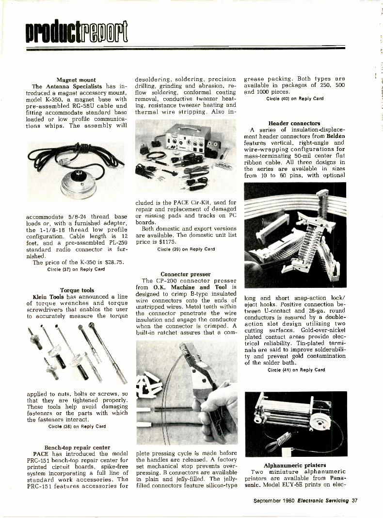
aroducimoN
Magnet mountThe Antenna Specialists has in-
troduced a magnet accessory mount,model K-350, a magnet base withpre -assembled RG-58U cable andfitting accommodate standard baseloaded or low profile communica-tions whips. The assembly will
accommodate 5/8-24 thread baseloads or, with a furnished adapter,the 1-1/8-18 thread low profileconfiguration. Cable length is 12
feet, and a pre -assembled PL -259standard radio connector is fur-nished.
The price of the K-350 is $28.75.Circle (37) on Reply Card
Torque toolsKlein Tools has announced a line
of torque wrenches and torquescrewdrivers that enables the userto accurately measure the torque
applied to nuts, bolts or screws, sothat they are tightened properly.These tools help avoid damagingfasteners or the parts with whichthe fasteners interact.
Circle (38) on Reply Card
Bench -top repair centerPACE has introduced the model
PRC-151 bench -top repair center forprinted circuit boards, spike -freesystem incorporating a full line ofstandard work accessories. ThePRC-15 1 features accessories for
desoldering, soldering, precisiondrilling, grinding and abrasion, re -flow soldering, conformal coatingremoval, conductive tweezer heat-ing, resistance tweezer heating andthermal wire stripping. Also in-
cluded is the PACE Cir-Kit, used forrepair and replacement of damagedor missing pads and tracks on PCboards.
Both domestic and export versionsare available. The domestic unit listprice is $1175.
Circle (39) on Reply Card
Connector presserThe CP-200 connector presser
from O.K. Machine and Tool isdesigned to crimp B -type insulatedwire connectors onto the ends ofunstripped wires. Metal teeth withinthe connector penetrate the wireinsulation and engage the conductorwhen the connector is crimped. Abuilt-in ratchet assures that a com-
plete pressing cycle is made beforethe handles are released. A factoryset mechanical stop prevents over -pressing. B connectors are availablein plain and jelly -filled. The jelly -filled connectors feature silicon -type
grease packing. Both types areavailable in packages of 250, 500and 1000 pieces.
Circle (40) on Reply Card
Header connectorsA series of insulation -displace-
ment header connectors from Beldenfeatures vertical, right-angle andwire -wrapping configurations formass -terminating 50 -mil center flatribbon cable. All three designs inthe series are available in sizesfrom 10 to 60 pins, with optional
long and short snap -action lock/eject hooks. Positive connection be-tween U -contact and 28-ga. roundconductors is assured by a double -action slot design utilizing twocutting surfaces. Gold -over -nickelplated contact areas provide elec-trical reliability. Tin-plated termi-nals are said to improve solderabili-ty and prevent gold contaminationof the solder bath.
Circle (41) on Reply Card
Alphanumeric printersTwo miniature alphanumeric
printers are available from Pana-sonic. Model EUY-5E prints on elec-
September 1980 Electronic Servicing 37
Product report
trosensitive paper, and the EUY-5Tprints on thermally -sensitive paper.Both versions print 32, 40, 64 or 80characters per line, formed by a7x5 dot matrix. Designed for OEMcustomers, the units come without acase, ready to be mounted into theuser's equipment and be connectedvia their ribbon cables and pcconnectors.
The EUY-5E is priced at $145, andthe EUY-5T at $196.
Circle (42) on Reply Card
Metric hand toolA metric hand tool, Super Champ
M2 from AMP Special Industries,crimps insulated and uninsulatedterminals and splices in wire sizes0.5 - 6.0 mm2. The wire barrel andinsulation barrel on insulated termi-nals and splices are crimped in thesame die. Color -coded dies in thetool nose correspond to colors onterminal insulation sleeves to ensureproper die selection. The tool fea-tures a wire cutter, bolt cutter, stud
gauge, wire stripper and universalignition crimping notch.
Circle (43) on Reply Card
Bonding systemDesigned to cut wire tie -down
costs, the Loctite Tak Pak Adhesivefor Printed Circuit Board Assemblyis capable of bonding electronic andelectrical components quickly, in
addition to wire tie -down. The TakPak Adhesive has been formulatedfor manual bench assembly, but itcan also be automated with off -the -shelf equipment such as the Bond-A-Matic 2000 Console.
Circle (44) on Reply Card
The bookthat turns businessmeninto best sellers.
Many who've read it are now reaping therewards. Because they've found that U.S.exports are a more than $100 billion a yearbusiness, that exporting creates both companyprofits and company growth, that U.S. goodshave never been more competitive ininternational markets. Above all, they'vefound that, with the help available from theU.S. Commerce Department, selling over-seas is no more difficult than selling at home.And this fact -filled book can prove the sameto you. Write The Secretary of Commerce,U.S. Dept. of Commerce, BED 8B,Washington, D.C. 20230.
U.S. Department of Commerce
A Public Service of This Magazine& The Advertising Council
38 Electronic Servicing September 1980
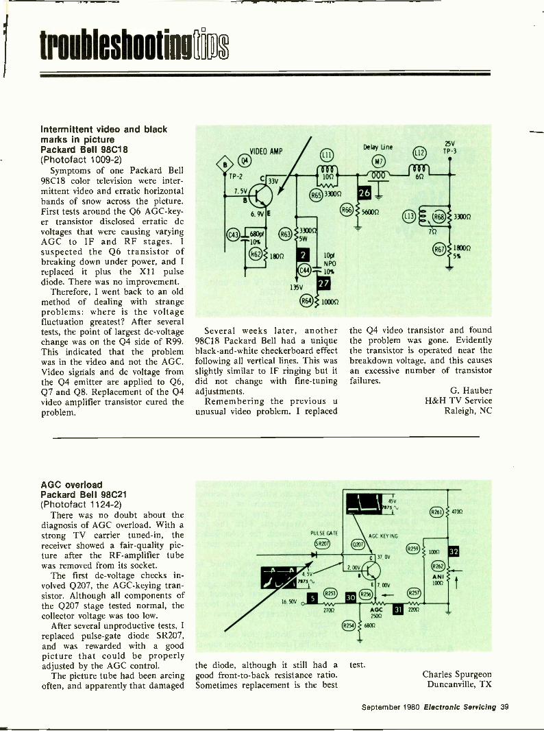
troubleshootinora
Intermittent video and blackmarks in picturePackard Bell 98C18(Photofact 1009-2)
Symptoms of one Packard Bell98C18 color television were inter-mittent video and erratic horizontalbands of snow across the picture.First tests around the Q6 AGC-key-er transistor disclosed erratic dcvoltages that were causing varyingAGC to IF and RF stages. Isuspected the Q6 transistor ofbreaking down under power, and Ireplaced it plus the X11 pulsediode. There was no improvement.
Therefore, I went back to an oldmethod of dealing with strangeproblems: where is the voltagefluctuation greatest? After severaltests, the point of largest dc -voltagechange was on the Q4 side of R99.This indicated that the problemwas in the video and not the AGC.Video signals and dc voltage fromthe Q4 emitter are applied to Q6,Q7 and Q8. Replacement of the Q4video amplifier transistor cured theproblem.
Several weeks later, another98C18 Packard Bell had a uniqueblack -and -white checkerboard effectfollowing all vertical lines. This wasslightly similar to IF ringing but itdid not change with fine-tuningadjustments.
Remembering the previous uunusual video problem, I replaced
the Q4 video transistor and foundthe problem was gone. Evidentlythe transistor is operated near thebreakdown voltage, and this causesan excessive number of transistorfailures.
G. HauberH&H TV Service
Raleigh, NC
AGC overloadPackard Bell 98C21(Photofact 1124-2)
There was no doubt about thediagnosis of AGC overload. With astrong TV carrier tuned -in, thereceiver showed a fair -quality pic-ture after the RF-amplifier tubewas removed from its socket.
The first dc -voltage checks in-volved Q207, the AGC-keying tran-sistor. Although all components ofthe Q207 stage tested normal, thecollector voltage was too low.
After several unproductive tests, Ireplaced pulse -gate diode SR207,and was rewarded with a goodpicture that could be properlyadjusted by the AGC control.
The picture tube had been arcingoften, and apparently that damaged
the diode, although it still had agood front -to -back resistance ratio.Sometimes replacement is the best
test.Charles SpurgeonDuncanville, TX
September 1980 Electronic Servicing 39
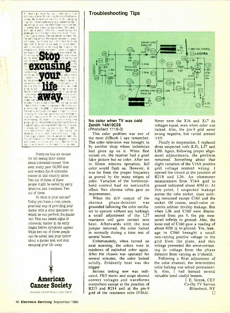
I haven't got cancer by now I'll never get k.want to know. No one in my family ever had ea'
anyway. My husband told me not to worry. I was gint;go but I remembered the goldfish needed feeding.
was raining out, and I was afraid I'd get sick on the wayoverslept and trussed my appointment. Who cares. I
don't have a doctor. I feel fine. I missed the bus. The:a.nary got out so I chased it around for hours. I forgot
had to get a haircut. The kids wanted ice cream first.The traffic was terrible. The weather was great so I playedkt,.,lf instead. I'm not sick, ever,. I don't have the 17.rght noel. If cancer's in* the stars, it's in the s'.t'went to the doctor's on the wrong day. I wentwrong doctor's. Maybe next week make it. It's as'..,ity religion. I'm a few pound:'m too busy rig s ^ u d fall apart v.,'
cue. My father or's and he ..until he was 90. about it. t h
coldt care.
I tho borneand fix dinner. boss 'i't giveme the day off a at sale on linensI couldn't. miss. rattle. No one inmy farn4 ever not. afraid of cancer. I
lost a button that football game on. Bythe time they find ly be toe late. I wasdoing laundry. I k a day in my life.Cancer of the what ring. In my businessI need every h orrow I couldn'tcare less But ising. I forgotbridge club me a is office is toofar away. I forgot to cash a check. y dug was lost, andI had to find it. It was hunting season. My clothes wereat the laundry. I feel great. It upsets me to talk about it
The kids would rip the house apart if I went out. I dit'tknow why. If I haven't got cancer by never get it.I just don't want to know. No one in my 5114 ever hadcancer anyway. My husband told me not to worry. I was
ing to go but I remembered the goldfish tieeded feeding.was raining out, and I was afraid I'd get sick on the wayoverslept and missed my appointment. Who cares. I
I have a doctor. I feel fine. I missed the' bus. Theunary got out so I chased a an,und fur hours. I forgot.
: had to get a haircut. The kids wanted ice cream fast.he traffic was terrible.. The weather was great no I played
instoa ! fir, t e.:Pr havo to tn. !(-y
Everyone has an excusefor not seeing their doctorabout colorectal cancer. How-ever, every year 52,000 menand women die of colorectalcancer in this country alone.Two out of three of thesepeople might be saved by earlydetection and treatment. Twoout of three.
So what is your excuse?Today you have a new, simple,practical way of providing yourdoctor with a stool specimen onwhich he can perform the guaiactest. This can detect signs ofcolorectal cancer in its earlystages before symptoms appear.While two out of three peoplecan be saved. Ask your doctorabout a guaiac test, and stopexcusing your life away.
AmericanCancer Society
ACE CONTRII-. ow A PUBLIC SERVICE.
Troubleshooting Tips
A24
B
.00110%
R214 8 R215Matched to 2%
B
CHROMA SYNC
PHASE DET
CATH
10000
2.2meg
2..2meg
CATH
CHROMA SYNC
PHASE BET
28V7875 'N.,
100031
35V
7875 'N.,
00022000 3.60
3.584C OSC CONTROL
A 6GH8A
1.I.5pf 1 250V
220pt
1KV
10%
ov
9
88. 92V
No color when TV was coldZenith 1 4A1 0C29(Photofact 1116-3)
This color problem was one ofthe most difficult I can remember.The color television was brought inby another shop whose technicianhad given up on it. When firstturned on, the receiver had a goodb&w picture but no color. After tento fifteen minutes operation, fullcolor would flash on. However, itwas far from the proper frequencyas proved by the many stripes ofcolor. Variation of the horizontal -hold control had no noticeableeffect. New chroma tubes gave noimprovement.
When the dcV output of thechroma phase -detector wasgrounded (allowing the color oscilla-tor to operate without any locking),a small adjustment of the L37reactance coil gave correct zerobeat. Afterwards with the testjumper removed, the color lockedin normally during a time test ofseveral hours.
Unfortunately, when turned onnext morning, the colors were inrainbows of unlocked color again.After the chassis was operated forseveral minutes, the color lockedsolidly. Evidently heat was thetrigger.
Serious testing now was indi-cated. FET-meter and scope showedcorrect voltages and waveformseverywhere except at the junction ofR215 and R214 and at the pin -9grid of the reactance tube (V16A).
Never were the X16 and X17 dcvoltages equal, even when color waslocked. Also, the pin -9 grid neverswung negative, but varied around+1V.
Finally in desperation, I replacedthree suspected coils (L35, L37 andL38). Again, following proper align-ment adjustments, the problemremained. Something about thatslight variation of the V16A positivegrid voltage seemed wrong. Iopened the circuit at the junction ofR218 and L36. An ohmmetermeasurement from V16A grid toground indicated about 40M 12 Atthis point, I suspected leakageacross the tube socket, since noth-ing remained except C160 and thesocket. Of course, small -value ce-ramics seldom develop leakage. Butwhen L36 and C160 were discon-nected from pin 9, the pin mea-sured infinity to ground. Also, theloose end of C160 gave a reading ofabout 40M 1/ to ground. Yes, leak-age in C160 brought a smallnon -varying positive voltage to thegrid from the plate, and thisvoltage prevented the error -correct-ing dc voltage from the phasedetector from varying as it'should.
Following a final adjustment ofthe color channel, the intermittentcolor locking was solved permanent-ly. Also, I had learned severalvaluable (and costly) lessons.
J. E. Strenk, CETCo -Op TV Service
Rhinebeck, NY0
40 Electronic Servicing September 1980
cailleis [Ey/A technical paper examining the
effects of aluminum electrolytic ca-pacitors on power supply filteringhas been released by Cornell-Dubili-er.
nationnotes
THE EFFECTS OF ALUMINUM ELECTROLYTICCAPACITOR PARAMETERS ON POWER
SUPPLY FILTERING
The article discusses types ofpower supplies and capacitor selec-tion considerations for each type ofsupply. Detail is given for switchingpower supplies, with descriptionsand recommendations for input andoutput capacitors.
Circle (45) on Reply Card
The ETCO Idea Book lists morethan 4000 hard -to -find items. The96 -page book is designed for use byhobbyists, teachers, students, hams,experimenters, researchers, deal-ers, technicians and manufacturers.
Circle (46) on Reply Card
A 10 -page color brochure, West-inghouse Vacuum Interrupters, de-scribes a line of vacuum interrup-ters manufactured by the industrialand government tube division ofWestinghouse..
The brochure contains brief casehistories on applications of industri-al and government tube divisionvacuum interrupters, manufacturedto both US and international stan-dards.
Circle (47) on Reply Card
ITT Schadow has published acatalog covering push buttons, keyswitches, rotary and slide switches.The 72 -page illustrated catalog fea-tures mechanical and electricaldata for all previous catalogueditems as well as many new switchesand front panel enhancement fea-tures. Also featured in the catalogis an option guide for quick selec-tion, a statement of product war-ranty, a glossary of terms andsuggestions for switch cleaning pro-cedures.
Circle (48) on Reply Card0
Heart attack or stroke couldknock you down on your way up.
You're working for the challenge,the satisfaction, the success, The lastthing you want is a heart attack orstroke. Yet, nearly one millionAmericans die of heart disease andstroke every year. And 200,000 ofthem die before retirement age.
The American Heart Associationis fighting to reduce early deathand disability from heart diseaseand stroke with research, profes-sional and public education, andcommunity service programs.
But more needs to be done.You can help us find the answers
by sending your dollars today toyour local Heart Association, listedin your telephone directory
Put your money whereyour Heart is.
AmericanHeartAssociation
WE'RE FIGHTING FOR YOUR LIFE
September 1980 Electronic Servicing 41
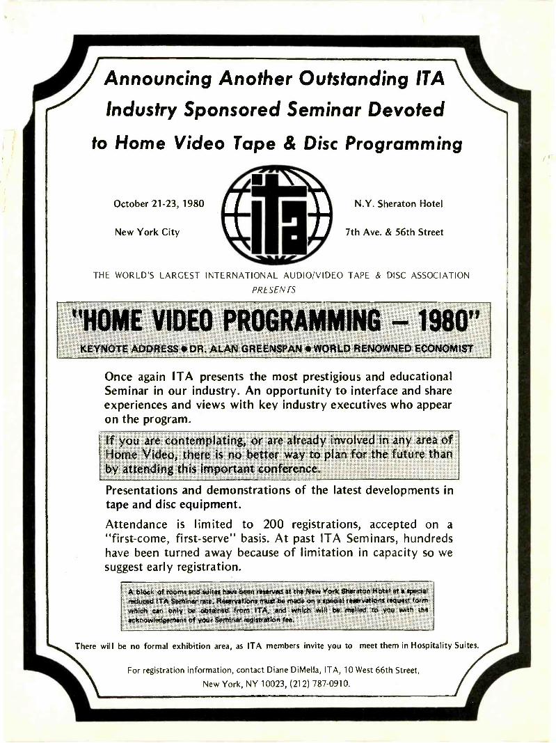
Announcing Another Outstanding ITA
Industry Sponsored Seminar Devoted
to Home Video Tape & Disc Programming
THE WORLD'S LARGEST INTERNATIONAL AUDIO/VIDEO TAPE & DISC ASSOCIATION
PRESENTS
NOTE ADDRESS * DR. ALAN GREE NSPAN * WORLD RENOWNED ECONOMIST
Once again ITA presents the most prestigious and educationalSeminar in our industry. An opportunity to interface and shareexperiences and views with key industry executives who appearon the program.
If you are contemplating, or are already involved in any area ofHome Video, there is no better way to plan for the future thanby attending this important conference.
Presentations and demonstrations of the latest developments intape and disc equipment.
Attendance is limited to 200 registrations, accepted on a"first -come, first -serve" basis. At past ITA Seminars, hundredshave been turned away because of limitation in capacity so wesuggest early registration.
A btotk of rooms arid suites hava been reserved at the New York Sheraton Hotel 8t a specialreduced ETA Seminar rate_ Reservations must be made on e special reservations request f4frft]:
*E'.4ieft oar, only be obtained from ETA, and which Will be mailed to you with4iiirtowledgerrrent of your Seminar riegistratiion lee.
There will be no formal exhibition area, as ITA members invite you to meet them in Hospitality Suites.
For registration information, contact Diane DiMelia, ITA, 10 West 66th Street,
New York, NY 10023, (212) 787-0910.
nattlexchanueThere is no charge for a listing in Readers Exchange foritems "Needed," but we reserve the right to select andedit all copy. Due to the limited amount of space for thisdepartment, "Needed" listings must contain no more thanthree items. If you can help with a request write directlyto the reader, not to Electronic Servicing. "For Sale"listings will be charged for and included in the regularclassified section of Electronic Servicing. Please consultthat section for price and ordering instructions.
Needed: IF transformer for Zenith radio model K725,Zenith number 95-1248, Meissner 16-6682, MillerRA -117. Edward N. Carroll, 1108 Georgia Ave.,Athens, TN 37303.
Needed: Operating manuals and/or schematics for thefollowing test equipment: Precision model 910 tubetester, RCA model 150 signal generator, and Solarmodel CF capacitor analyzer. G. J. Kulp, 1115 LilacLn., West Lawn, PAe19609.
Needed: One flyback transformer for pin A30527 -A for1965 Ambassador model 4T40 portable TV. BillMessina, 53 Railroad Ave., Norwood, MA 02012.
Needed: Power/filament transformer for Zenith modelchassis 1005. Zenith part number 95-630N. TomModica, P.O. Box 347, Everson, WA 98247.
Needed: Schematics for Kenwood model TK-350 tuner,and an Audotron model WM-101 tape player. Will buyor copy and return. Also need a Heathkit 1G-28color/bar generator. Steves Radio Service, P.O. Box168, Wickes, AR 71973.
Needed: York model B/E -124 radio. FM/AM/MB/SWswitch must be in good condition. L. E. Vargas, 8921Roosevelt Blvd., Philadelphia, PA 19152.
Needed: Sencore CR31A, VA -48, LC -53, B&K-Precision1077B and 467. Price must be below 1/2 list. Ed Tate,8218 Jeffries Ave., Cleveland, OH 44105.
Needed: Socket adapter kit MX949/U for Suprememodel 1-177-B tube tester. Also need operation manualfor a Sencore TM116 tube tester modernizing panel.Larry Anderson, 3453 Balsam Ave., N.E., GrandRapids, MI 49505.
Needed: System Electronics model 57 3 -inch scope,schematic and manual, or current address ofcompany. Ken Dolan, 286 S. Seymour St., Napa, CA94558.
Needed: Sylvania D122000 chassis. Electronic Emer-gency Ward, 1603 Park Ave. So. Plainfield, NJ 07080.
A Centuryin America
, ..\The Salvation Army -invades- the United State',
Highlights ofSalvation Army HistoryMarch 10, 1880-A group of Salvationists,seven women and one man, landed in NewYork City. Their first act was to kneel and prayon the cobblestones. Then they set to work,helping the needy and preaching the Gospel.
1917-18-The Salvation Army won the hearts ofthe doughboys serving in the trenches duringWorld War I. General John J. Pershing praised"the Sallies" for "the degree of excellence andself-sacrifice in the work performed which hasbeen second to none."1930's-" No man need steal, starve, or commitsuicide; come to The Salvation Army." Thissaying was sorely tested during the depressionyears when the Army fed and shelteredthousands of the unemployed. In New YorkCity, the Army's emergency relief work in-creased 700 per cent in two years.
Today-There are over 1,000 Salvation Armycorps community centers-in middle classsuburbs, inner-city ghettoes, and small-townmain streets. To some, The Salvation Army istheir church home. To others, a social servicecenter which helps in times of need. Toyoungsters, an after -school recreation center.To all, an open door for anyone who needs itsspiritual or practical ministries.
September 1980 Electronic Servicing 43
nmarketalaceAdvertising rates in the Classified Section are 35cents per word, each Insertion, and must beaccompanied by cash to insure publication.
Each initial or abbreviation counts a full word.
Minimum classified charge $3.00.
For ads on which replies are sent to us forforwarding (blind ads), there Is an additionalcharge of $3.00 per Insertion to cover departmentnumber, processing of replies, and mailing costs.
Classified columns are not open to advertising ofany products regularly produced by manufactur-ers unless used and no longer owned by themanufacturer or distributor.
For SaleAUTOMOBILE RADIO and tape replacementparts: Delco, Chrysler, Philco-Ford, Motorola,Panasonic and many others. Large Inventory.Laren Elecritonics, Inc., 3768 Boston Road,Bronx, NY 10469, (212) 881-9600, out of New YorkState, (80P) 223-8314. 5-79-tf
TV & RADIO TUBES, 36 cents EA!! Free colorcatalog. Cornell, 4221 University, San Diego,Californal 92104. 8-76-tf
30 CHANNELCABLE TV
CONVERTER
ORDER No. 196AE047
ROUTE 9N,PLATTSBURGFi, N.Y. 12901Tel.: (518) 561-8700.
Circle (10) on Reply Card
advertisers' rm
Gamit Enterprises,Inc. 17
Klein Tools, Inc 11
Kurz-Kasch Inc 7
OelrichPublications 23
OK Machine &Tool Corp. IFC
Phipps & Bird, Inc 1
RCA TechnicalPublications IBC
Howard W. Sams& Co., Inc. 3
ELECTRONIC SURPLUS: CLOSEOUTS, LIQUIDA-TIONS! Parts, equipment stereo, Industrial,educational. Amazing values! Fascinating Itemsunavailable in stores or catalogs anywhere. Un-usual FREE catalog. ETC0-011, Box 762, Platts-burgh, N.Y. 12901. 6-78-tf
TV RENTAL SYSTEMS! Complete & guaranteed.Manual or computerized, Send $2.00 for completedetails. Perry's rental systems, 133 BrendaStreet, Milton, Florida 32570. 2-80-tfn
PRINTED CIRCUIT boards from your sketch orartwork. Affordable prices. Also fun kit projects.Free details DANOCINTHS INC. Dept. ES, Box261, Westland, MI 48185. 5-80-8t
PICTURE TUBE REBUILDING EQUIPMENT capa-ble of producing four high quality tubes per day(WILL TRAIN TO OPERATE) $3600. Call or writeAtoll Television, 6425 Irving Park, Chicago,Illinois 60634, ph. 312-545-6667. 8-80-31
STROBE WARNING LIGHTS-PARTS, REPAIRS:R. Cecil, 805 South Penn, Roswell, New Mexico88201. 8-80-2t
TELEPHONE CALLS recorded automatically, un-attended, build yourself for less than $10.00.Detailed plan $2.50. Garrett Electronic, 6451-AImperial Ave., San Diego, California 92114 8-80-61
PICTURE TUBE REBUILDING EQUIPMENT capa-ble of producing four high quality tubes per day(WILL TRAIN TO OPERATE) $3600. Call or writeAtoll Television, 6425 Irving Park, Chicago,Ilinois 60634, ph. 312-545-6667. 9-80-3t
CAPACITOR KITS, FACTORY DIRECT! Subminia-ture Aluminum Electrolytics and Solid Tantalum.Send $3 for catalog, prices and 3 samples. Beatdistributor costs, keep stock up, costs low! ACTNOW! Cash or check; no C.O.D.'s. J. G. STEELECO., Inc., Box 422, McKenzie, TN 38201, Ph.(901) 352-5109. 9-80-3t
100 TUNERS $5.00 each plus shipping. Dan's TV,P.O. Box 42, Osakis, MN 56360, (612) 859-2851.
9-80-1 t
SCRAMBLED TELEVISION, encoding/decoding.New book. Theory/circuits. $9.95 plus $1shipping. Workshop, Box 393ES, Dept. C, Beth-page, N.Y. 11714. 7-80-tf
Electronic Servicing®Advertising Sales Offices
NATIONAL SALES MANAGERGreg Garrison, P.O. Box 12901Overland Park, KS 66212Phone: (913) 888-4664
NEW YORK, NEW YORKJoe Concert, 4 West 58th St.New York, NY 10019Phone: (212) 888-1977
LOS ANGELES, CALIFORNIAHerbert A. Schiff3055 Wilshire Blvd., Suite 350Los Angeles, CA 90010Phone: (213) 387-0639
LONDON, ENGLANDJohn Ashcroft & Co., 12 Bear St.Leicester Square, London, WC2H 7ASPhone: 930-0525Telex: 895-2387
AMSTERDAM, HOLLANDJohn Ashcroft & Co., John J. LucassenAkerdijk 150A, 1171 PV-BadhoevedorpPhone: 2968-6226
TOKYO, JAPANInternational Media Representatives, Ltd.2-29, Toranomon 1-chome, Minato-kuTokyo 105Phone: 502-0656
LOCKING NEEDLENOSE PLIERSI HOSPITALQUALITY FORCEPS. 1001 USES! HEAT SINK;HOLDS TRANSISTORS WHILE SOLDERING;REACHES HARD -TO -GET -AT PARTS. GAP FORVARIED USES. INSTRUCTIONS INCLUDED.FINGER HOLES INSURE SAFE, NON -SLIPUSAGE. $10.95 FOR THREE! (ONE WITH INSU-LATED HANDLES) $1.00 SHIPPING -HANDLING.OKLAHOMANS ADD 39 cents TAX EACH SET.ELECTRONIC ENTERTAINMENT LTD., P.O. BOX416, NICOMA PARK, OK. 73066. 9-80-1t
MODULES-ZENITH DEALERS KITS, 800-902 and800-902A with case, new, $225. Granzella, Wheat-land, MO 65779. 9-80-1t
SYLVANIA CK3000 COLOR TEST JIG withcomplete adapters for Sylvania and RCA. Instruc-tions and set-up charts, $295. Sencore YF33 Yokeand Flyback Tester with schematic, instructioncassette and manual. $125. Both in mint condi-tion. M. Mc Burney, 7140 Marymount, Goleta,Calif. 93017. 9-80-1 t
HELP WANTED
TELEVISION TECHNICIANS-Experience neces-sary, top pay, medical benefits, paid vacations.Enjoy a new "Life5,4de" In a beautiful, friendly,smog free, full service desert community. Sendyour resume to 225 E. Ridgecrest Blvd., Ridge -crest, California 93555. Telephone 714-375-1361ask for Service Manager. 3-80-tfn
Business OpportunitySAVE HUNDREDS: American Made qualityHead -Ends, V/V, U/V Converters, Camera Modu-lators, Amplifiers for small CATV systems.Mid -band available. Factory prices. Send $5.00(or letterhead). Box 809, Boyton Beach, Fla.33435. 8-80-tfn
TV SERVICE SHOP near SHAW AFB and Sumter,SC. Fully equipped. Warranty station for 3 majorbrands-$10,000. Terms. Write Box 1164, Sumter,SC 29150. 9-80-2t
C. E.T.FOR TECHNICIANS WHO TAKE PRIDE
IN THEIR PROFESSION
CERTIFIED ELECTRONICS TECHNICIANCertification is available in the following areas:AUDIO MATVCOMMUNICATIONS MEDICALINDUSTRIAL RADIO -TV
Write to: THE INTERNATIONAL SOCIETYOF CERTIFIED ELECTRONICS TECHNICIANS2708 West Berry, Fort Worth, TX 76109
Please send me:
0 Free booklet: CAREERS IN THE ELEC-TRONICS INDUSTRY (a stamped self-addressed envelope is enclosed)
0 Information about the CET Test.0 A list of test administrators in my
state/country.
9 I am already a CET. Send me informationabout ISCET membership. CET No.
NAME
ADDRESS
CITY STATE
ZIP PHONE (_Zenith Radio Corp. BC
44 Electronic Servicing September 1980
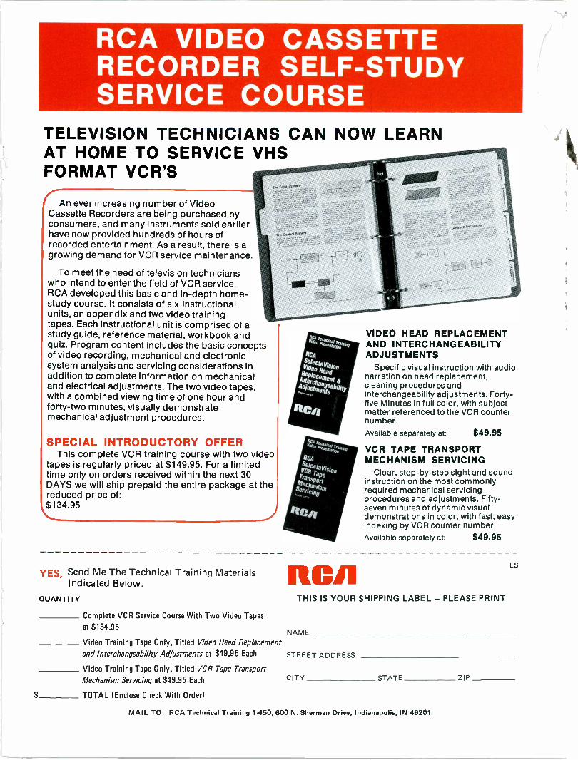
RCA VIDEO CASSETTERECORDER SELF -STUDYSERVICE COURSE
TELEVISION TECHNICIANS CAN NOW LEARNAT HOME TO SERVICE VHSFORMAT VCR'S
IAn ever increasing number of VideoCassette Recorders are being purchased byconsumers, and many instruments sold earlierhave now provided hundreds of hours ofrecorded entertainment. As a result, there is agrowing demand for VCR service maintenance.
To meet the need of television technicianswho intend to enter the field of VCR service,RCA developed this basic and in-depth home-study course. It consists of six instructionalunits, an appendix and two video trainingtapes. Each instructional unit is comprised of astudy guide, reference material, workbook andquiz. Program content includes the basic conceptsof video recording, mechanical and electronicsystem analysis and servicing considerations inaddition to complete on mechanicaland electrical adjustments. The two video tapes,with a combined viewing time of one hour andforty-two minutes, visually demonstratemechanical adjustment procedures.
SPECIAL INTRODUCTORY OFFERThis complete VCR training course with two video
tapes is regularly priced at $149.95. For a limitedtime only on orders received within the next 30DAYS we will ship prepaid the entire package at thereduced price of:$134.95
VIDEO HEAD REPLACEMENTAND INTERCHANGEABILITYADJUSTMENTS
Specific visual instruction with audionarrationcleaning procedures andinterchangeability adjustments. Forty-five Minutes in full color, with subjectmatter referenced to the VCR counternumber.Available separately at: $49.95
VCR TAPE TRANSPORTMECHANISM SERVICING
Clear, step-by-step sight and soundinstruction on the most commonlyrequired mechanical servicingprocedures and adjustments. Fifty-seven minutes of dynamic visualdemonstrations in color, with fast, easyindexing by VCR counter number.Available separately at: $49.95
YES, Send Me The Technical Training MaterialsIndicated Below.
QUANTITY
Complete VCR Service Course With Two Video Tapes
at $134.95
Video Training Tape Only, Titled Video Head Replacement
and Interchangeability Adjustments at $49.95 Each STREET ADDRESS
Video Training Tape Only, Titled VCR Tape Transport
Mechanism Servicing at $49.95 Each
TOTAL (Enclose Check With Order)
RCATHIS IS YOUR SHIPPING LABEL - PLEASE PRINT
ES
NAME
CITY STATE ZIP
MAIL TO: RCA Technical Training 1450, 600 N. Sherman Drive, Indianapolis, IN 46201
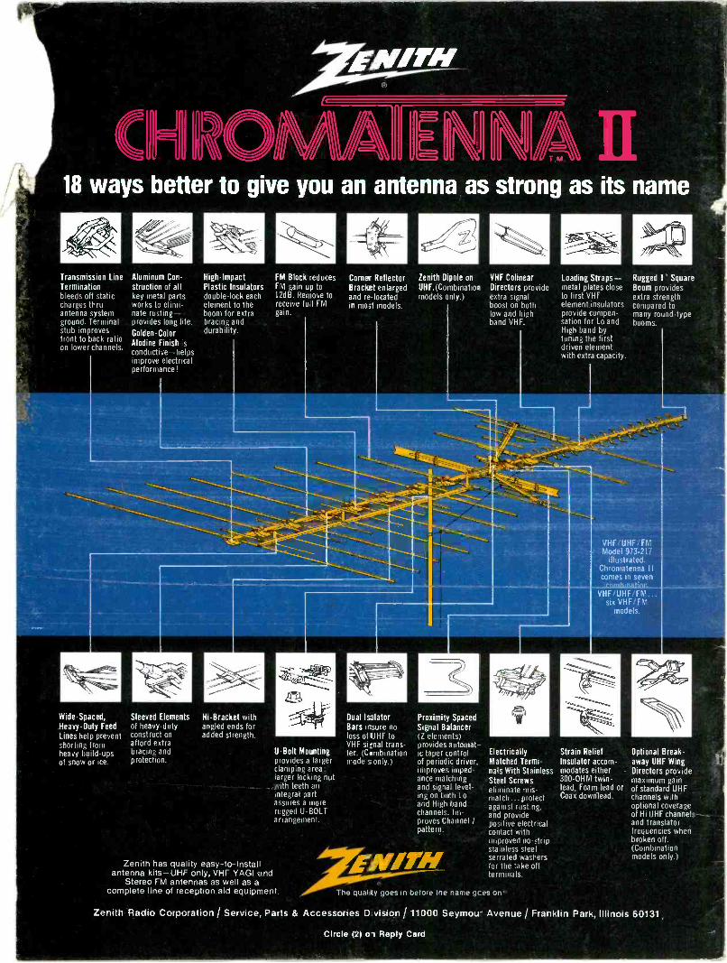
18 ways
better to give youan
antenna as strongas its nam
e
Transm
ission LineA
luminum
Con-
High Im
pact
Term
inationstruction of all
Plastic Insulators
bleeds off statickey m
etal partsdouble -lock each
charges thruw
orks toelem
ent to the
antenna systemnate rusting-
boom for extra
ground. Term
inalprovides long life.
bracing and
stub improves
Golden -C
olordurability.
front to back ratioA
lodine Finish is
on lower channels.
conductive-helpsim
prove electricalperform
ance!
Wide -S
paced,S
leeved Elem
ents
Heavy -D
uty Feed
of heavy-duty
Lines help preventconstruction
shorting fromafford extra
heavy build-upsbracing and
of snow or ice.
protection.
Hi -B
racket with
angled ends foradded strength. F
M B
lock reducesF
M gain up to
12dB. R
emove to
receive full FM
gain.
U -B
olt Mounting
provides a largerclam
ping area;larger locking nutw
ith teeth anintegral partassures a m
orerugged U
-BO
LT
arrangement.
Zenith has quality easy -to
-installantenna kits-U
HF
only,V
HF
YA
GI and
Stereo F
M antennas as w
ell as acom
plete line of receptionaid equipm
ent.
Corner R
eflectorB
racket enlargedand re locatedin m
ost models.
Dual Is3lator
Bars insure no
loss of UH
F to
VH
F signal trans-
fer. (Com
binationm
odels only.)
Zenith D
pole onU
HF
.(Co itination
models only.)
Proxim
ity Spaced
Signal B
alancerZ
elements)
provides automat-
ic taper controlof periodic driver.im
proves imped-
ance matching
and signal level-ing on both Loand H
igh bandchannels. Im
-proves C
hannel]pattern.
VH
F C
olinearD
irectors provideextra signalboost on bothlow
and highband V
HF
.
Electrically
Matched T
ermi-
nals With S
tainlessS
teel Screw
selim
inate mis
match... protect
against rusting,and providepositive electricalcontact w
ithim
proved no -stripstainless steelserrated w
ashersfor the take offterm
inals.
The quality goes in before
the name gces on-.
Loading Straps-
metal plates close
to first VH
Felem
ent insulatorsprovide com
pen-sation for Lo andH
igh band bytuning the firstdriven e em
entw
ith extra capacity.
Rugged 1" S
quareB
oom provides
extra strengthcom
pared tom
any round -typeboom
s.
VH
F/U
HF
. fM
odel 913-21illustrated.
Chrom
atenna IIcom
es in seven
Strain R
eliefInsulator accom
-m
odates either300 -O
HM
twin -
lead, Foam
lead orC
oax download.
Optional B
reak-aw
ay UH
F W
ingD
irectors providem
aximum
gainof standard U
HF
channels with
optional coverageof H
i UH
F channels --
and translator,
frequencies when
broken off.(C
ombination
models only.)
Zenith R
adio Corporation
/ Service, P
arts &A
ccessories D vision /
11000 Seym
ou- Avenue
/ Franklin P
ark, Illinois60131,
Circle (2) 01 R
eply Card