electron spectrograph with a hyperbolic electrostatic field
TRANSCRIPT
ISSN 1063�7842, Technical Physics, 2012, Vol. 57, No. 2, pp. 242–246. © Pleiades Publishing, Ltd., 2012.Original Russian Text © L.A. Baranova, 2012, published in Zhurnal Tekhnicheskoi Fiziki, 2012, Vol. 82, No. 2, pp. 85–89.
242
INTRODUCTION
Most electron energy analyzers currently avail�able operate as a spectrometer: they have a detectorand the electron spectrum is recorded sequentially byscanning over an energy range. If the energy range ofinterest is very wide, as, for example, in the case ofAuger spectroscopy or photoelectron spectroscopy,when characteristics peaks fall into the interval fromseveral tens of electronvolts to about 2500 eV (i.e., inthe energy range 1 : 25), such a way of detection takestoo much time. Moreover, it becomes fully unaccept�able if time�varying processes are studied. In thiscase, the total spectrum should be taken several timesin short time intervals so as to judge processes takingplace on the surface (absorption, electron�impact�induced damage, etc.) from the shape and height ofpeaks.
This problem can be solved using a spectrographthat can cover the whole spectrum falling into anenergy range of interest at a time. As electron detec�tors, position�sensitive detectors, the performance ofwhich has being continuously improving in recentyears, can be applied. The main challenge here is tofind and implement the electrostatic field distributionproviding simultaneous focusing of electron beamswith energies differing by nearly two orders of magni�tude on a flat detector.
Until recently, the desired field configuration couldbe provided only in a parallel�plate capacitor. How�ever, it cannot solve the problem, since the dispersionof a parallel�plate capacitor grows with the electronenergy linearly. Therefore, to record a spectrum in theenergy interval 1 : 25, the device either must be unac�ceptably long or have a poor resolution in low� andmedium�energy ranges.
It was suggested [1, 2] that a hyperbolic field beused for simultaneously recording electron spectra in awide energy range. Such a field can be produced, for
example, by a quadrupole lens. It was shown [1] thatthe hyperbolic field provides first�order entrance anglefocusing of all electron beams irrespective of theirenergy and has a dispersion proportional to the squareroot of the electron energy. Hence, the extension ofthe spectrum in such a detector is much smaller thanin the parallel�plate capacitor. This field is two�dimensional and, as well as the field of the parallel�plate capacitor, does not focus electrons in the direc�tion that is normal to the dispersion plane. As a result,the electron collection solid angle (relative aperture ofthe analyzer) is small compared with, for example, acylindrical mirror.
In [3, 4], the feasibility of creating a cylindricalmirror spectrograph notable for a large electron col�lection solid angle was considered. Numerical simula�tion was made of a cylindrical mirror to the outer elec�trode of which a potential linearly increasing along theaxis was applied. Under these conditions, the distribu�tion of the electric field inside the analyzer is near�hyperbolic. Such a line of inquiry seems promising,although first�order focusing conditions now becomedependent on the electron energy. It is therefore nec�essary to empirically select a law of the potential distri�bution on the outer cylinder that would provide satis�factory focusing in a given energy interval.
In this work, a hyperbolic field is produced by aparallel�plate capacitor with a linear distribution ofthe potential on the upper electrode. Such an analyzeris numerically simulated with the CPO3D program[5]. The feasibility of increasing the analyzer’s relativeaperture by providing focusing in the direction normalto the dispersion plane, i.e., by providing doublefocusing, is discussed.
Electron Spectrograph with a Hyperbolic Electrostatic FieldL. A. Baranova
Ioffe Physical Technical Institute, Russian Academy of Sciences, Politekhnicheskaya ul. 26, St. Petersburg, 194021 Russiae�mail: [email protected]
Received April 5, 2011
Abstract—The electron–optical properties of an energy analyzer representing a parallel�plate capacitor witha linear distribution of the potential on the upper plate are studied. It is shown that first�order focusing con�ditions in this analyzer do not depend on the particle energy and the linear dispersion is proportional to thesquare root of the energy. Such an analyzer can simultaneously record an electron spectrum in a wide energyrange, that is, operate as a spectrograph. Double focusing conditions in a box�type analyzer are found, whichallows the relative aperture of the spectrograph to be raised several�fold.
DOI: 10.1134/S1063784212020041
ELECTRON AND ION BEAMS, ACCELERATORS
TECHNICAL PHYSICS Vol. 57 No. 2 2012
ELECTRON SPECTROGRAPH WITH A HYPERBOLIC ELECTROSTATIC FIELD 243
NUMERICAL SIMULATIONOF A PARALLEL�PLATE CAPACITOR
WITH A POTENTIAL LINEAR DISTRIBUTION ALONG THE REFLECTING ELECTRODE
The 2D hyperbolic field (the field of a quadrupolelens) is described by the formula
(1)
In the plane y = 0, the potential is zero, while in theplane y = d, the potential varies with coordinate z lin�early,
(2)
It follows that hyperbolic field (1) between the platesof a parallel�plate capacitor can be formed if the lowerplate (the plane y = 0) is grounded and the upper plate(y = d) is under a potential linearly varying with coor�dinate z according to formula (2). The energy analyzeruses only the first quadrant of the field of the quadru�pole lens (y and z are positive); therefore, on one side(the plane z = 0), the plates of the capacitor should beconnected to each other by a flat electrode that is nor�mal to the plates and under a zero potential. In thisway, we obtain a structure in which two mutually per�pendicular electrodes are grounded and the third elec�trode (parallel to the first electrode and perpendicularto the second one) is under a potential linearly varyingin the z direction from zero to W = VL, where L is thelength of the capacitor.
Such an analyzer was numerically simulated usingthe program CPO3D, which allows setting a potentialacross the electrodes that linearly varies along the zcoordinate. Distance d between the plates of thecapacitor is taken for the unit of length. In devicesintended for Auger spectroscopy or photoelectronspectroscopy, this distance usually equals several cen�timeters. The plates measure 5d along the z axis and 6din the transverse direction. In the plane z = 0, theplates are connected to each other by a solid groundedelectrode. Since the plates of the capacitor are finite insize, two thin rectangular frames are placed over theperimeter of the analyzer at distances y = 0.33d andy = 0.66d from the lower plate. These frames are underthe potential calculated by formula (1).
The numerical simulation showed that (i) if anelectron source is on the lower plate at the point (z = 0,y = 0), first�order entrance angle focusing conditionsdo not depend on the electron energy; (ii) the entranceangle (the angle between the velocity vector and thelower plate) at which focusing takes place equals α =24.7°; and (iii) the position of the focus on the z axisvaries in proportion to the square root of the electronenergy.
Electrons are focused on the lower plate of thecapacitor, where a position�sensitive detector shouldbe placed. This poses no difficulties. However, it isalmost impossible to place an analyte on or near the
Φ y z,( ) Vyz
d2���� .=
Φ z( ) V zd�� .=
lower plate. For the analyte to be irradiated by acharged particle beam or by photons, it must be faraway from the analyzer. Therefore, the next step was togain insight into the electron–optic properties of thehyperbolic mirror in the case of a remote electronsource. The entrance slit was made in the groundedside plate (z = 0) at the joint with the lower plate.(If the slit is made in the lower plate, it will be 2.5 timeswider, since the entrance angle is much smaller than45°.) The position of the source was set by the coordi�nates z = –0.5d and y = –0.2d.
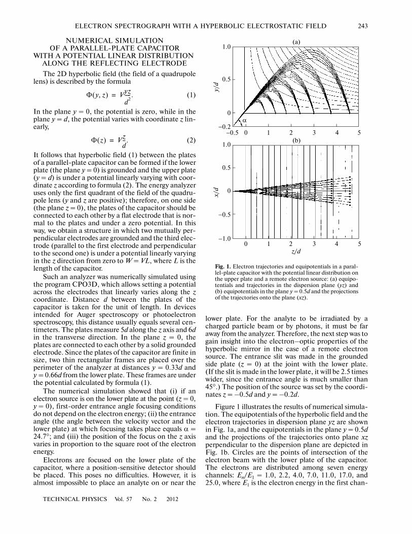
Figure 1 illustrates the results of numerical simula�tion. The equipotentials of the hyperbolic field and theelectron trajectories in dispersion plane yz are shownin Fig. 1a, and the equipotentials in the plane y = 0.5dand the projections of the trajectories onto plane xzperpendicular to the dispersion plane are depicted inFig. 1b. Circles are the points of intersection of theelectron beam with the lower plate of the capacitor.The electrons are distributed among seven energychannels: En/E1 = 1.0, 2.2, 4.0, 7.0, 11.0, 17.0, and25.0, where E1 is the electron energy in the first chan�
α
1.0
0.5
0
−0.2−0.5 0 1 2 3 4 5
1.0
0.5
0
−0.5
−1.00 1 2 3 4 5
z/d
(a)
(b)
y/d
x/d
Fig. 1. Electron trajectories and equipotentials in a paral�lel�plate capacitor with the potential linear distribution onthe upper plate and a remote electron source: (a) equipo�tentials and trajectories in the dispersion plane (yz) and(b) equipotentials in the plane y = 0.5d and the projectionsof the trajectories onto the plane (xz).
244
TECHNICAL PHYSICS Vol. 57 No. 2 2012
BARANOVA
nel and En is the electron energy in the nth channel.The entrance angle is α = 23.26°, and the apex angleof the beam is 2° in the dispersion plane and 2γ = 5.7°in the perpendicular plane.
It turned out that, in the case of a remote source,first�order focusing conditions in the hyperbolic fieldbecome slightly dependent on the electron energy. Ifthe entrance angle of electrons is such that first�orderfocusing conditions are met in the middle of theenergy interval, a lower energy electron beam will befocused in the plane that is slightly above the lowerplate of the capacitor, while a higher energy beam willbe focused slightly below the lower plate. This effect isweakly pronounced, but the resolving power of theanalyzer still drops.
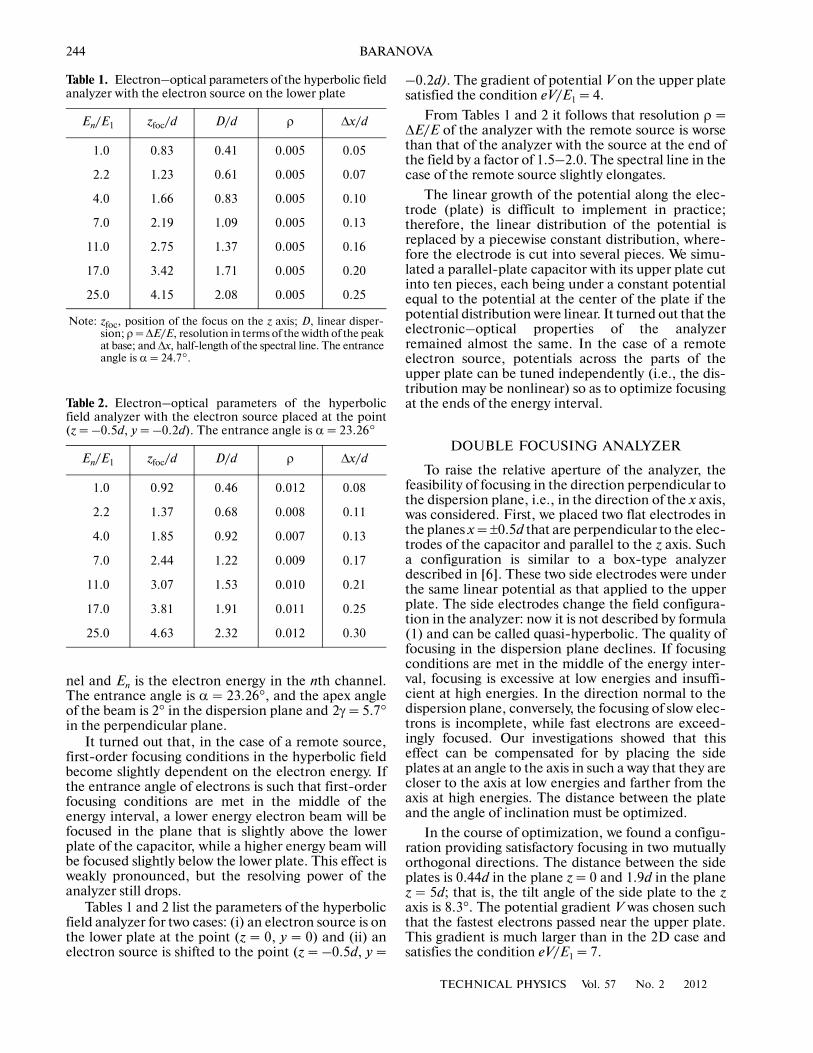
Tables 1 and 2 list the parameters of the hyperbolicfield analyzer for two cases: (i) an electron source is onthe lower plate at the point (z = 0, y = 0) and (ii) anelectron source is shifted to the point (z = –0.5d, y =
–0.2d). The gradient of potential V on the upper platesatisfied the condition eV/E1 = 4.
From Tables 1 and 2 it follows that resolution ρ =ΔE/E of the analyzer with the remote source is worsethan that of the analyzer with the source at the end ofthe field by a factor of 1.5–2.0. The spectral line in thecase of the remote source slightly elongates.
The linear growth of the potential along the elec�trode (plate) is difficult to implement in practice;therefore, the linear distribution of the potential isreplaced by a piecewise constant distribution, where�fore the electrode is cut into several pieces. We simu�lated a parallel�plate capacitor with its upper plate cutinto ten pieces, each being under a constant potentialequal to the potential at the center of the plate if thepotential distribution were linear. It turned out that theelectronic–optical properties of the analyzerremained almost the same. In the case of a remoteelectron source, potentials across the parts of theupper plate can be tuned independently (i.e., the dis�tribution may be nonlinear) so as to optimize focusingat the ends of the energy interval.
DOUBLE FOCUSING ANALYZER
To raise the relative aperture of the analyzer, thefeasibility of focusing in the direction perpendicular tothe dispersion plane, i.e., in the direction of the x axis,was considered. First, we placed two flat electrodes inthe planes x = ±0.5d that are perpendicular to the elec�trodes of the capacitor and parallel to the z axis. Sucha configuration is similar to a box�type analyzerdescribed in [6]. These two side electrodes were underthe same linear potential as that applied to the upperplate. The side electrodes change the field configura�tion in the analyzer: now it is not described by formula(1) and can be called quasi�hyperbolic. The quality offocusing in the dispersion plane declines. If focusingconditions are met in the middle of the energy inter�val, focusing is excessive at low energies and insuffi�cient at high energies. In the direction normal to thedispersion plane, conversely, the focusing of slow elec�trons is incomplete, while fast electrons are exceed�ingly focused. Our investigations showed that thiseffect can be compensated for by placing the sideplates at an angle to the axis in such a way that they arecloser to the axis at low energies and farther from theaxis at high energies. The distance between the plateand the angle of inclination must be optimized.
In the course of optimization, we found a configu�ration providing satisfactory focusing in two mutuallyorthogonal directions. The distance between the sideplates is 0.44d in the plane z = 0 and 1.9d in the planez = 5d; that is, the tilt angle of the side plate to the zaxis is 8.3°. The potential gradient V was chosen suchthat the fastest electrons passed near the upper plate.This gradient is much larger than in the 2D case andsatisfies the condition eV/E1 = 7.
Table 1. Electron–optical parameters of the hyperbolic fieldanalyzer with the electron source on the lower plate
En/E1 zfoc/d D/d ρ Δx/d
1.0 0.83 0.41 0.005 0.05
2.2 1.23 0.61 0.005 0.07
4.0 1.66 0.83 0.005 0.10
7.0 2.19 1.09 0.005 0.13
11.0 2.75 1.37 0.005 0.16
17.0 3.42 1.71 0.005 0.20
25.0 4.15 2.08 0.005 0.25
Note: zfoc, position of the focus on the z axis; D, linear disper�sion; ρ = ΔE/E, resolution in terms of the width of the peakat base; and Δx, half�length of the spectral line. The entranceangle is α = 24.7°.
Table 2. Electron–optical parameters of the hyperbolicfield analyzer with the electron source placed at the point(z = –0.5d, y = –0.2d). The entrance angle is α = 23.26°
En/E1 zfoc/d D/d ρ Δx/d
1.0 0.92 0.46 0.012 0.08
2.2 1.37 0.68 0.008 0.11
4.0 1.85 0.92 0.007 0.13
7.0 2.44 1.22 0.009 0.17
11.0 3.07 1.53 0.010 0.21
17.0 3.81 1.91 0.011 0.25
25.0 4.63 2.32 0.012 0.30
TECHNICAL PHYSICS Vol. 57 No. 2 2012
ELECTRON SPECTROGRAPH WITH A HYPERBOLIC ELECTROSTATIC FIELD 245
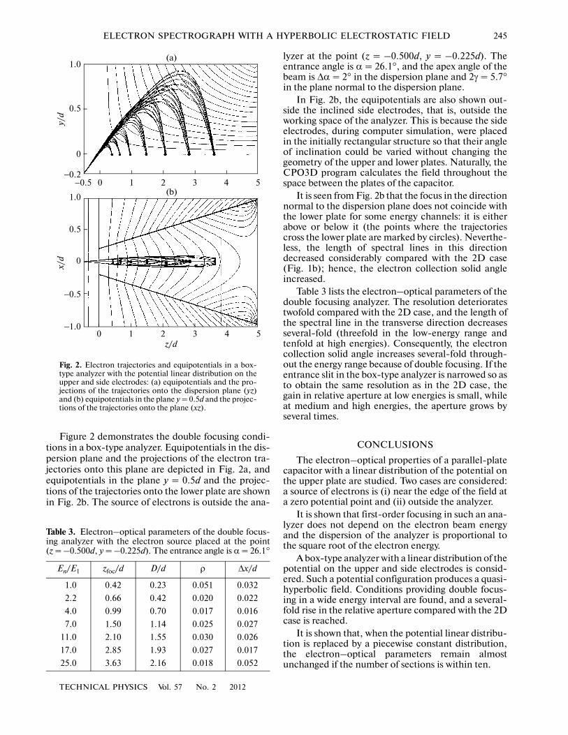
Figure 2 demonstrates the double focusing condi�tions in a box�type analyzer. Equipotentials in the dis�persion plane and the projections of the electron tra�jectories onto this plane are depicted in Fig. 2a, andequipotentials in the plane y = 0.5d and the projec�tions of the trajectories onto the lower plate are shownin Fig. 2b. The source of electrons is outside the ana�
lyzer at the point (z = –0.500d, y = –0.225d). Theentrance angle is α = 26.1°, and the apex angle of thebeam is Δα = 2° in the dispersion plane and 2γ = 5.7°in the plane normal to the dispersion plane.
In Fig. 2b, the equipotentials are also shown out�side the inclined side electrodes, that is, outside theworking space of the analyzer. This is because the sideelectrodes, during computer simulation, were placedin the initially rectangular structure so that their angleof inclination could be varied without changing thegeometry of the upper and lower plates. Naturally, theCPO3D program calculates the field throughout thespace between the plates of the capacitor.
It is seen from Fig. 2b that the focus in the directionnormal to the dispersion plane does not coincide withthe lower plate for some energy channels: it is eitherabove or below it (the points where the trajectoriescross the lower plate are marked by circles). Neverthe�less, the length of spectral lines in this directiondecreased considerably compared with the 2D case(Fig. 1b); hence, the electron collection solid angleincreased.
Table 3 lists the electron–optical parameters of thedouble focusing analyzer. The resolution deterioratestwofold compared with the 2D case, and the length ofthe spectral line in the transverse direction decreasesseveral�fold (threefold in the low�energy range andtenfold at high energies). Consequently, the electroncollection solid angle increases several�fold through�out the energy range because of double focusing. If theentrance slit in the box�type analyzer is narrowed so asto obtain the same resolution as in the 2D case, thegain in relative aperture at low energies is small, whileat medium and high energies, the aperture grows byseveral times.
CONCLUSIONS
The electron–optical properties of a parallel�platecapacitor with a linear distribution of the potential onthe upper plate are studied. Two cases are considered:a source of electrons is (i) near the edge of the field ata zero potential point and (ii) outside the analyzer.
It is shown that first�order focusing in such an ana�lyzer does not depend on the electron beam energyand the dispersion of the analyzer is proportional tothe square root of the electron energy.
A box�type analyzer with a linear distribution of thepotential on the upper and side electrodes is consid�ered. Such a potential configuration produces a quasi�hyperbolic field. Conditions providing double focus�ing in a wide energy interval are found, and a several�fold rise in the relative aperture compared with the 2Dcase is reached.
It is shown that, when the potential linear distribu�tion is replaced by a piecewise constant distribution,the electron–optical parameters remain almostunchanged if the number of sections is within ten.
1.0
0.5
0
−0.2−0.5 0 1 2 3 4 5
1.0
0.5
0
−0.5
−1.00 1 2 3 4 5
z/d
(a)
(b)
y/d
x/d
Fig. 2. Electron trajectories and equipotentials in a box�type analyzer with the potential linear distribution on theupper and side electrodes: (a) equipotentials and the pro�jections of the trajectories onto the dispersion plane (yz)and (b) equipotentials in the plane y = 0.5d and the projec�tions of the trajectories onto the plane (xz).
Table 3. Electron–optical parameters of the double focus�ing analyzer with the electron source placed at the point(z = –0.500d, y = –0.225d). The entrance angle is α = 26.1°
En/E1 zfoc/d D/d ρ Δx/d
1.0 0.42 0.23 0.051 0.032
2.2 0.66 0.42 0.020 0.022
4.0 0.99 0.70 0.017 0.016
7.0 1.50 1.14 0.025 0.027
11.0 2.10 1.55 0.030 0.026
17.0 2.85 1.93 0.027 0.017
25.0 3.63 2.16 0.018 0.052

246
TECHNICAL PHYSICS Vol. 57 No. 2 2012
BARANOVA
Thus, a parallel�plate capacitor with a potentiallinear distribution across a reflecting electrode andside electrodes seems to be promising for electronbeam analysis in a wide energy interval; i.e., it canoperate as an electron spectrograph.
REFERENCES
1. M. Jacka, M. Kirk, M. M. El Gomati, and M. Prutton,Rev. Sci. Instrum. 70, 2282 (1999).
2. M. Jacka, A. Kale, and N. Traitler, Rev. Sci. Instrum.74, 4298 (2003).
3. F. H. Read, Rev. Sci. Instrum. 73, 1129 (2002).
4. F. H. Read, D. Cubric, S. Kumashiro, and A. Walker,Nucl. Instrum. Methods Phys. Res. A 519, 338 (2004).
5. CPO programs, available from www.electronoptic.com
6. V. P. Afanas’ev and S. Ya. Yavor, Electrostatic EnergyAnalyzers for Charged�Particle Beams (Nauka, Moscow,1978) [in Russian].