electromagnetically penetrable objects · remote sensing of subsurface electromagnetically...
TRANSCRIPT
REMOTE SENSING OF SUBSURFACE ELECTROMAGNETICALLY
PENETRABLE OBJ ECTS
Reginald Eze & George Sivulka
LANDMINE AND IMPROVISED EXPLOSIVE DEVICE DETECTION
1. City University of New York, Laguardia Community College2. Regis High School
Cont ent s● Worldwide Landmine Problem● Subsurface Sensing Overview
What is subsurface sensing? Electromagnetic Wave ScatteringSensing and imaging technologiesBarriers, limitations, and common issues
● Simulating the real life problem in COMSOL MultiphysicsImplementing Electromagnetic Wave PropertiesScattering Physics
● Improving Simulation Accuracy Perfectly Matched Layers Soil layer variations
● Results and Conclusion

Regions CasualtiesAfrica 33,627
Asia-Pacific 16,390
Americas 8,558
Russia 7,202
Europe 4,628
Middle East and .North Africa
3,171
Total 73,576 [9]
(1999-2008)
Since 1975, more than 500,000civilians (50% children) have been killed or maimed by landmines [8]
The Worldwide LandmineProblem

➔ Tens of millions of live mines remain buried in 70 countries◆ Most of these countries
make up ⅔ of the world’s poorest nations [8]
◆ Removal costs: $300–$1000 per mine [11]Cheap removal is extremely important
➔ Solution:SUBSURFACE SENSING
[10]
The Worldwide LandmineProblem
Afghanistan 10,000,000; Angola 15,000,000; Azerbaijan 100,000; Bosnia and Herzegovina 3,000,000; Cambodia 6,000,000; Chad 70,000; China 10,000,000; Croat ia 3,000,000, Cyprus 16,942, Denmark 9,900, Ecuador 60,000, Egypt 23,000,000, El Salvador 10,000; Erit rea 1,000,000; Ethiopia 500,000, Falklands Islands (Malvinas) 25,000; Georgia 150,000l Guatemala 1,500l Honduras 35,000 Iran, Islamic Republic of 16,000,000 Iraq 10,000,000 Korea, Republic of 206,193 Latvia 17,000 Lebanon 8,795 Liberia 18,250 Mozambique 3,000,000 Namibia 50,000 Nicaragua 108,297 Rwanda 250,000 Somalia 1,000,000 Sudan 1,000,000 Ukraine 1,000,000 Viet Nam 3,500,000 Yemen 100,000
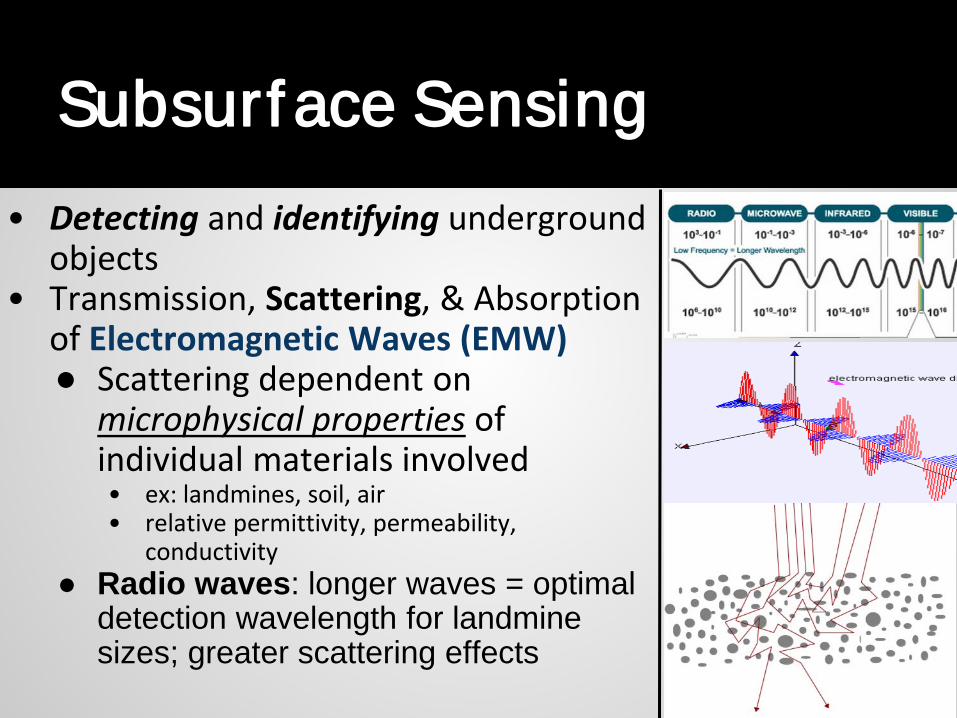
Subsurf ace Sensing• Detecting and identifying underground
objects• Transmission, Scattering, & Absorption
of Electromagnetic Waves (EMW)● Scattering dependent on
microphysical properties of individual materials involved • ex: landmines, soil, air• relative permittivity, permeability,
conductivity ● Radio waves: longer waves = optimal
detection wavelength for landmine sizes; greater scattering effects

Comsol Multiphysics Software allows modal creation and an accurate computational simulation of a subsurface sensing scenario
Sequence of Simulation CreationGeometry CreationDefining MaterialsDefining BoundariesMeshingSpecify Solver EquationsPost Processing
Simulat ing t he Real World Problem in COMSOL Sof t ware
}
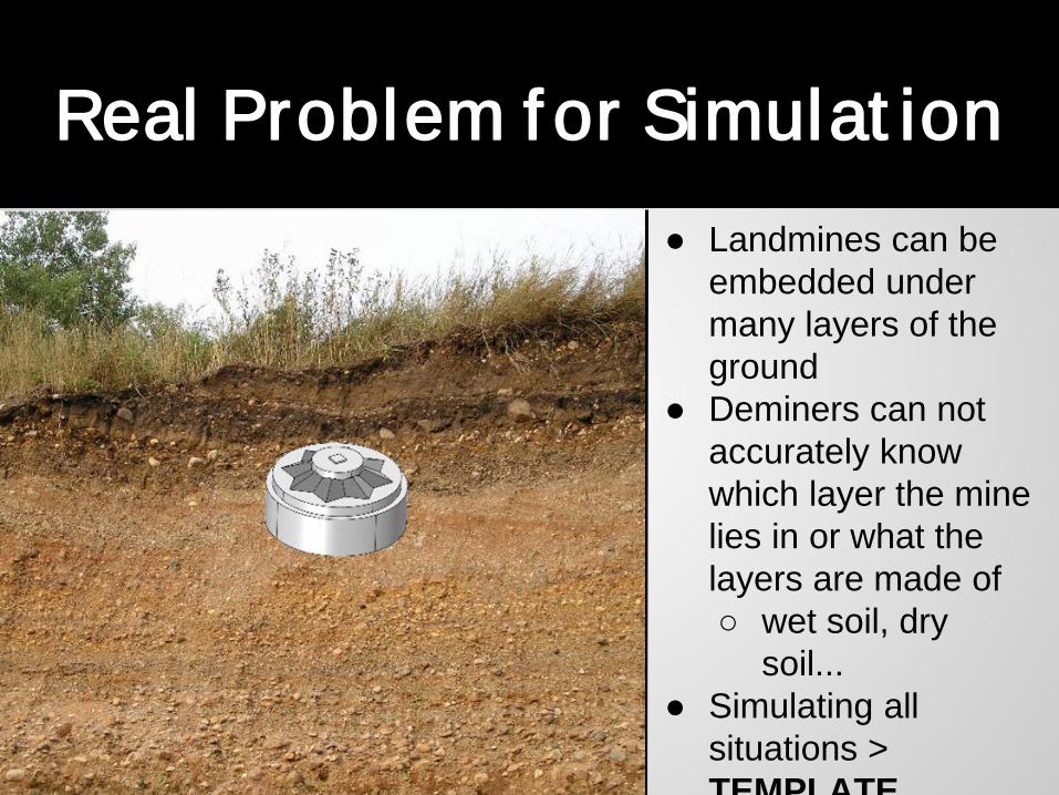
Real Problem f or Simulat ion ● Landmines can be
embedded under many layers of the ground
● Deminers can not accurately know which layer the mine lies in or what the layers are made of○ wet soil, dry
soil...● Simulating all
situations > TEMPLATE

Dist inguishing Landmines f rom Ot her AnomaliesAverage Specifications
Diameter: 20-125 mm Length: 50-100 mmWeigh as little as 30gBuried Shallowly Various shapes
Specific Microphysical PropertiesMaterial Relative
permittivityRelative permeability
Conductivity
Air 1 1 0
Dry Soil 2.9 1273+31i 0.004
Wet Soil 4 1756+395i 0.049
TNT/IED Composition
2.86 1256+2.26i 2.86e-4
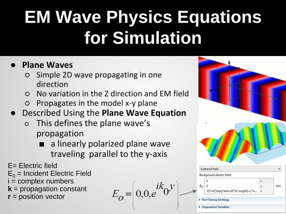
EM Wave Physics Equations for Simulation
● Plane Waves○ Simple 2D wave propagating in one
direction○ No variation in the Z direction and EM field ○ Propagates in the model x-y plane
● Described Using the Plane Wave Equation○ This defines the plane wave’s
propagation ■ a linearly polarized plane wave
traveling parallel to the y-axisE= Electric fieldE0 = Incident Electric Fieldi = complex numbersk = propagation constantr = position vector
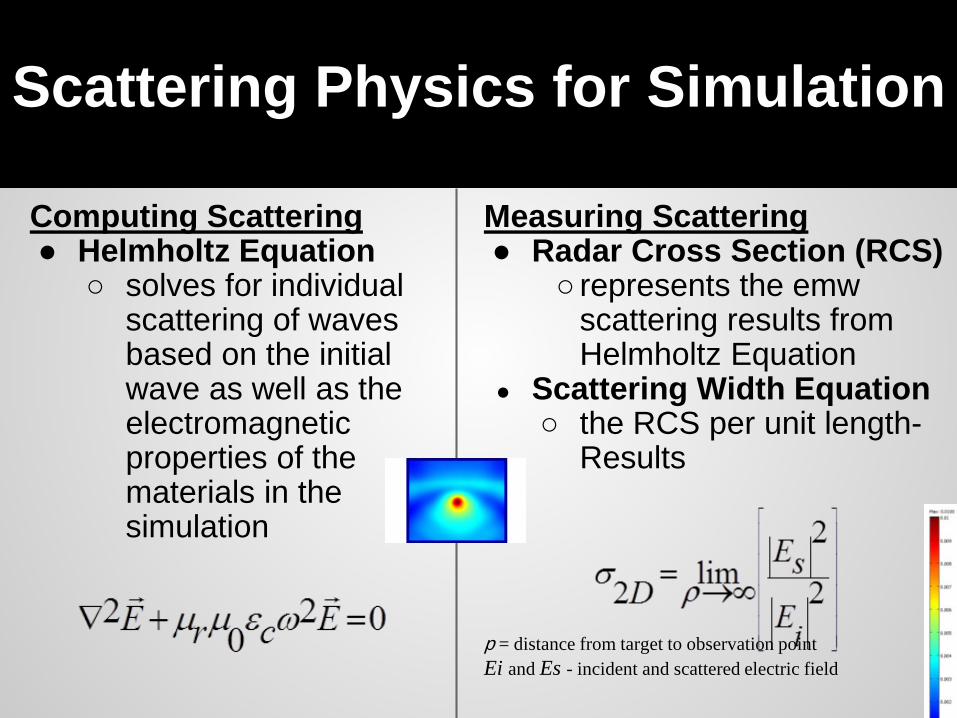
Scattering Physics for Simulation
Measuring Scattering● Radar Cross Section (RCS)
○ represents the emw scattering results from Helmholtz Equation
● Scattering Width Equation○ the RCS per unit length-
Results
p = distance from target to observation pointEi and Es - incident and scattered electric field
Computing Scattering● Helmholtz Equation
○ solves for individual scattering of waves based on the initial wave as well as the electromagnetic properties of the materials in the simulation
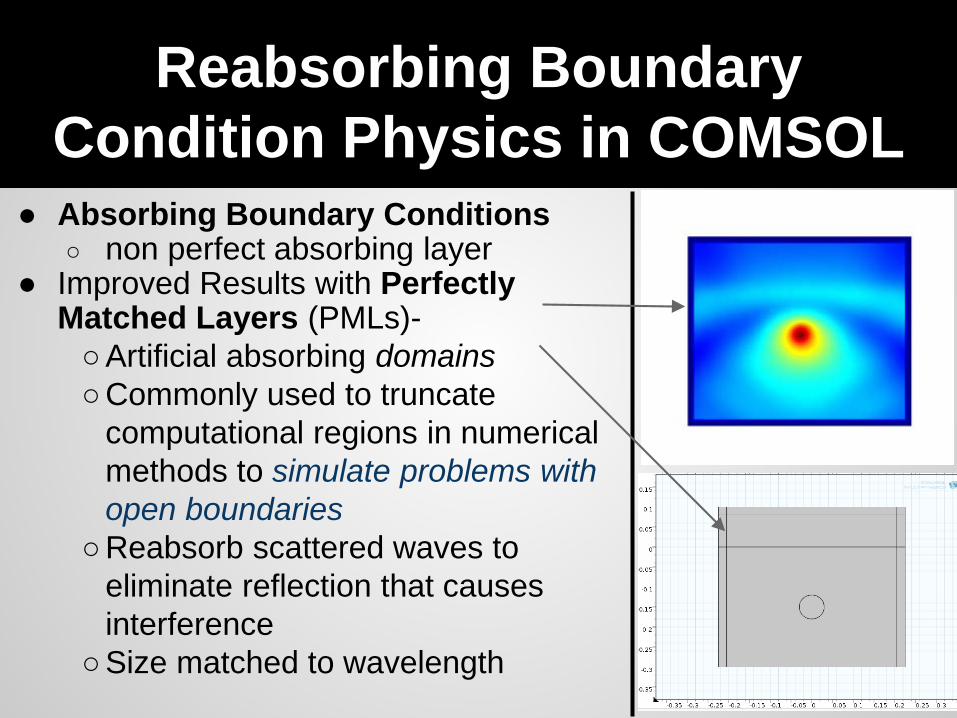
Reabsorbing Boundary Condition Physics in COMSOL
● Absorbing Boundary Conditions○ non perfect absorbing layer
● Improved Results with Perfectly Matched Layers (PMLs)-○Artificial absorbing domains○Commonly used to truncate
computational regions in numerical methods to simulate problems with open boundaries
○Reabsorb scattered waves to eliminate reflection that causes interference
○Size matched to wavelength
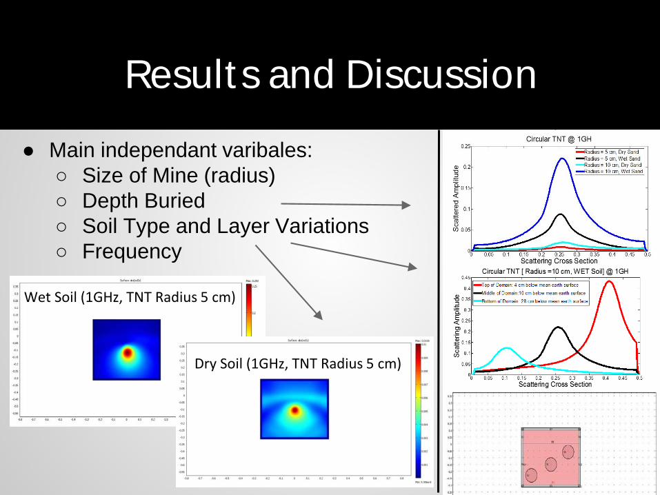
Results and Discussion
● Main independant varibales:○ Size of Mine (radius)○ Depth Buried○ Soil Type and Layer Variations○ Frequency
Wet Soil (1GHz, TNT Radius 5 cm)
Dry Soil (1GHz, TNT Radius 5 cm)
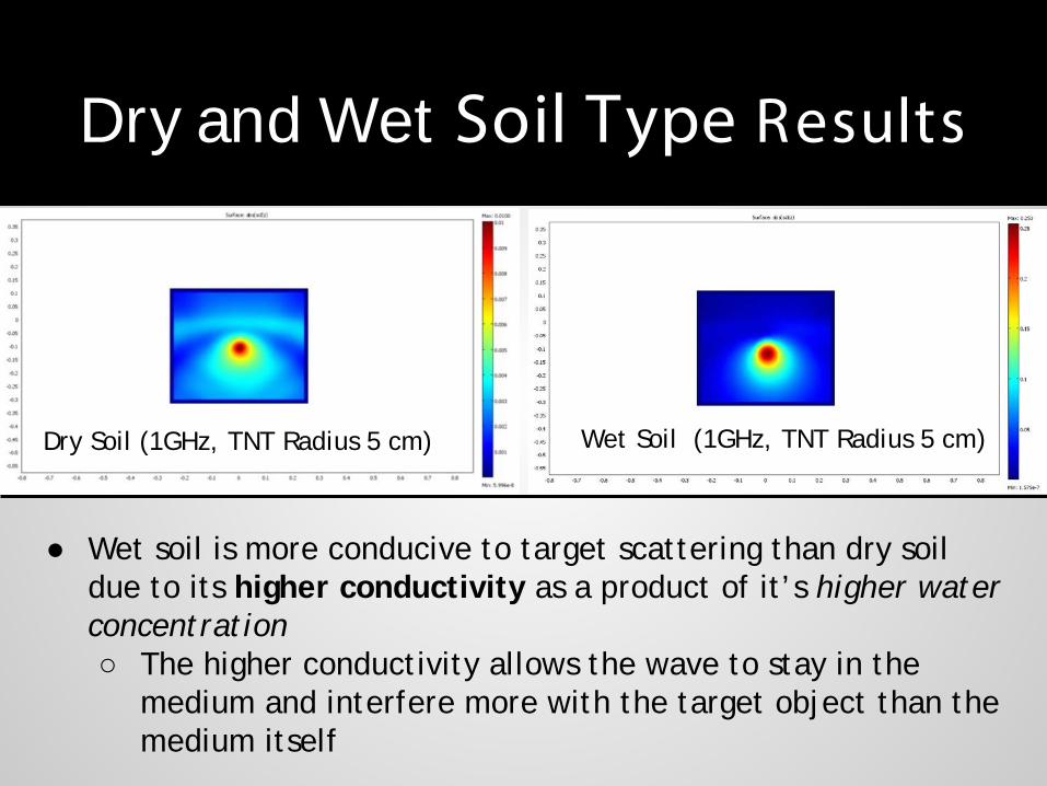
Dry and Wet Soil Type Results
Dry Soil (1GHz, TNT Radius 5 cm)
● Wet soil is more conducive to target scattering than dry soil due to its higher conductivity as a product of it’s higher water concentration○ The higher conductivity allows the wave to stay in the
medium and interfere more with the target object than the medium itself
Wet Soil (1GHz, TNT Radius 5 cm)
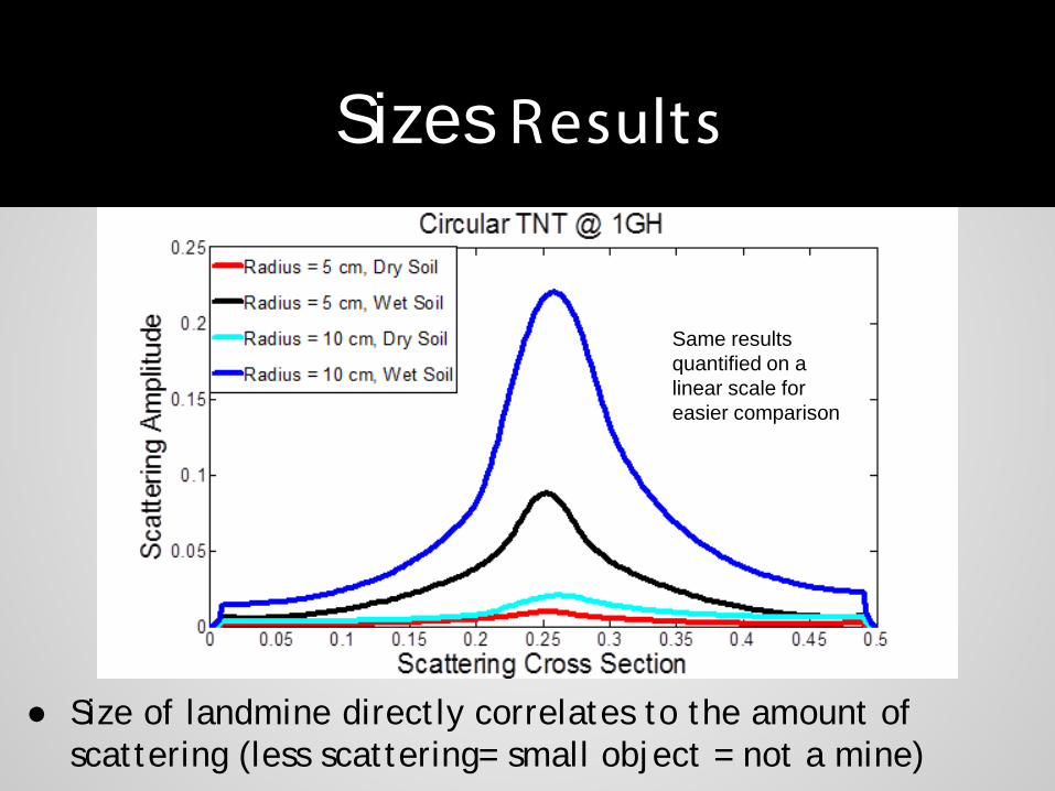
Sizes Results
● Size of landmine directly correlates to the amount of scattering (less scattering= small object = not a mine)
Same results quantified on a linear scale for easier comparison

Depth Variation Results
● TNT from higher up in the domain produces the highest amplitude of scattered waves and is most easily detected (landmines buried shallowly)

Soil Layer Scat tering Amplitudes Comparison
Air/Wet/Dry Soil Scattering(1GHz, TNT Radius 5 cm)
Air/Dry/Wet Soil Scattering(1GHz, TNT Radius 5 cm)
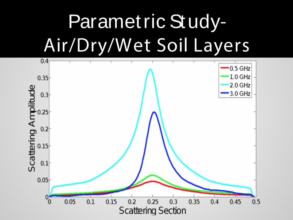
Paramet ric Study-Air/Dry/Wet Soil Layers
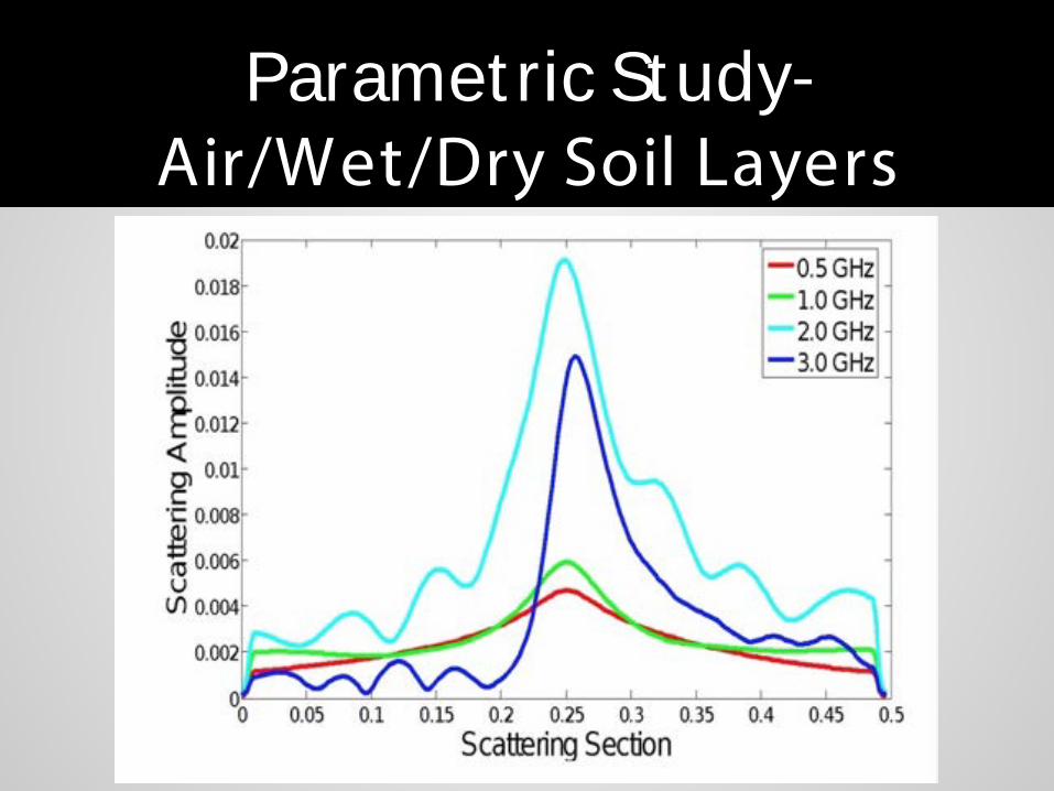
Paramet ric Study-Air/Wet/Dry Soil Layers
Paramet ric Study- Wavelengths & Soil Layers

CONCLUSION
●Successfully developed a template of various variations that may affect subsurface sensing of landmines in real world Ground Penetrating Radar situations○ The template can also be applied to other sub-surface
imaging problems with similar variations●Future research and goals
○Test variables of ■other compositions of soil (clay, sand, silt)■ different explosive types (RDX, C4, tetryl etc.)■ variations in surface roughness
1. http://missemmafry.wordpress.com/tag/landmine-victims/2. http://www.kayelaby.npl.co.uk/.
3. Christiansen, T. (2012). The ABC’s of RFID: physics, oilfield usageUnderstanding of antenna frequencies and topologies, how they impact performance help to tailor solution for oil/gas industry. Understanding of antenna frequencies and topologies, how they impact performance help to tailor solution for oil/gas industry.
4. Gander, M. J. (2011). Are Absorbing Boundary Conditions. History of Absorbing Boundary Conditions.
5. Hastings, F. D. (1995). Application of the perfectly matched layer (PML) absorbing. 3061-3069.
6. E.M.A. Hussein, E. W. (2000). Landmine detection: the problem and the challenge. Applied Radiation and Isotopes, 557-563.
7. Ronald W. Gamache, C. R. (2006). A Comparison of FDFD and FEM Methods Applied to the Buried Mine Problem. Excerpt from the Proceedings of the COMSOL Users Conference 2006 Boston.
8 COMSOL M lti h i 4 3 D t ti B t 2012
Ref erences

Thank You!

Boundary Condition Physics In Comsol
● Boundary conditions necessary to truncate numerical domain● Scattering Boundary Conditions
○ The boundary condition is transparent for an incoming electromagnetic waves.
○ It allows it to pass through perfectly matched layer.○ The boundary condition are also used when we want boundaries
to be transparent for scattering electromagnetic waves.● PML- not a boundary condition in reality
○ Artificial absorbing domains○ Commonly used to truncate computational regions in
numerical methods to simulate problems with open boundaries
○ Reabsorb all scattered waves to eliminate reflection that causes interference


Ground Penet rat ing Radar
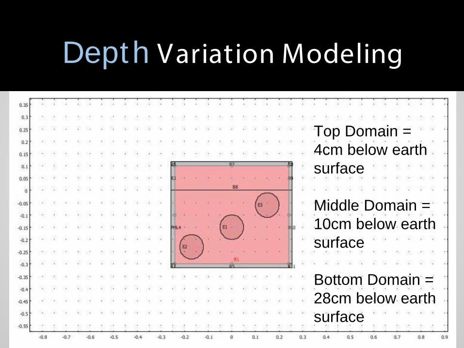
Depth Variation Modeling
Top Domain = 4cm below earth surface
Middle Domain = 10cm below earth surface
Bottom Domain = 28cm below earth surface
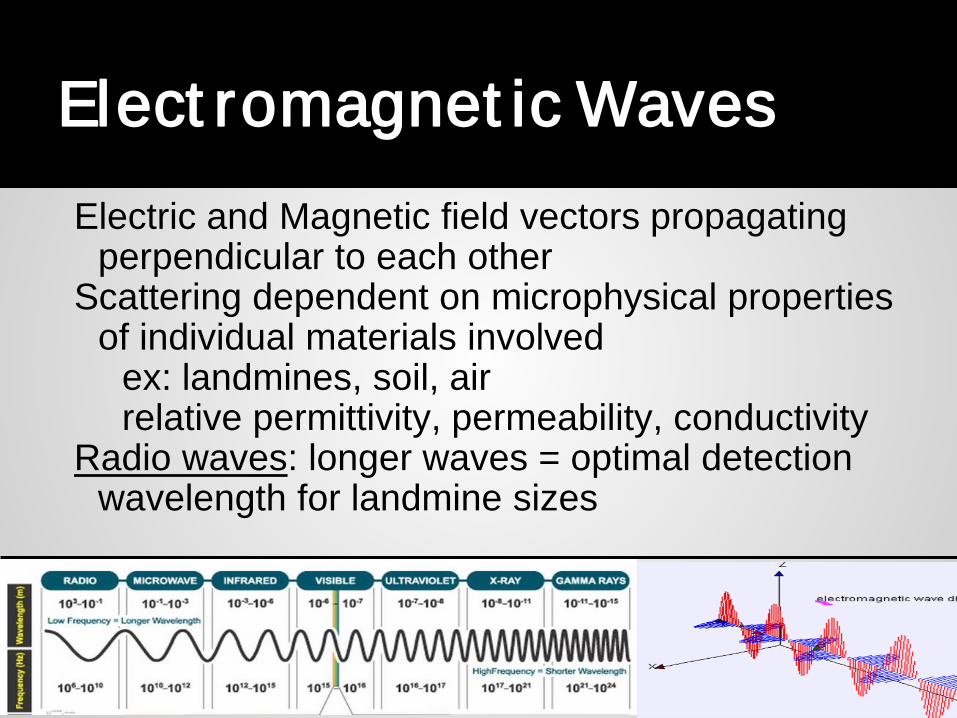
Elect romagnet ic WavesElectric and Magnetic field vectors propagating
perpendicular to each otherScattering dependent on microphysical properties
of individual materials involved ex: landmines, soil, airrelative permittivity, permeability, conductivity
Radio waves: longer waves = optimal detection wavelength for landmine sizes
Wet Soil Type Results
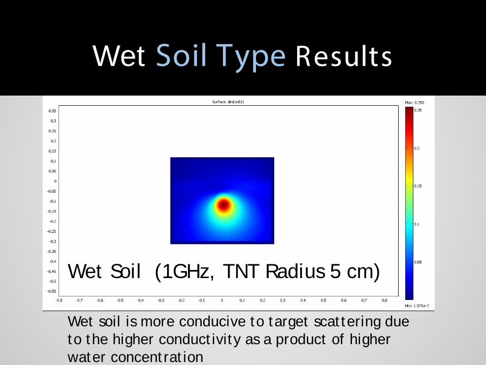
Wet Soil (1GHz, TNT Radius 5 cm)
Wet soil is more conducive to target scattering due to the higher conductivity as a product of higher water concentration

Subsurf ace Sensing• Detecting and identifying
underground objects• Transmission, Scattering, and
Absorption of Electromagnetic Waves (EMW)
• CenSSIS- Center for Subsurface Sensing and Imaging Systems● biomedical, environmental, and
geophysical problems• Problem: distinguishing the effect
that the medium has on the EM wave from that of the desired object

Thank You!

Material Relative permittivity
Relative permeability
Conductivity
Air 439.2 1 0
Dry Soil 1273+31i 2.9 0.004
Wet Soil 1756+395i 4 0.049
TNT 2.9 1 4.8e-4
Microphysical Parameters of Materials
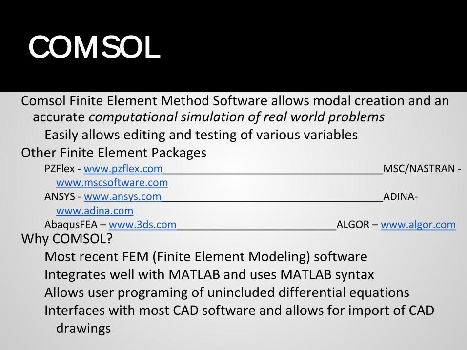
Comsol Finite Element Method Software allows modal creation and an accurate computational simulation of real world problems
Easily allows editing and testing of various variables Other Finite Element Packages
PZFlex - www.pzflex.com MSC/NASTRAN -www.mscsoftware.com
ANSYS - www.ansys.com ADINA-www.adina.com
AbaqusFEA – www.3ds.com ALGOR – www.algor.comWhy COMSOL?
Most recent FEM (Finite Element Modeling) software Integrates well with MATLAB and uses MATLAB syntaxAllows user programing of unincluded differential equationsInterfaces with most CAD software and allows for import of CAD
drawings
COMSOL
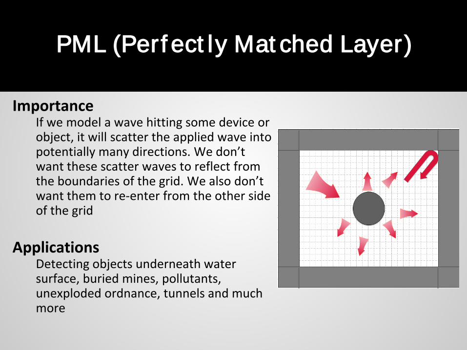
ImportanceIf we model a wave hitting some device or object, it will scatter the applied wave into potentially many directions. We don’t want these scatter waves to reflect from the boundaries of the grid. We also don’t want them to re-enter from the other side of the grid
ApplicationsDetecting objects underneath water surface, buried mines, pollutants, unexploded ordnance, tunnels and much more
PML (Perf ect ly Mat ched Layer)
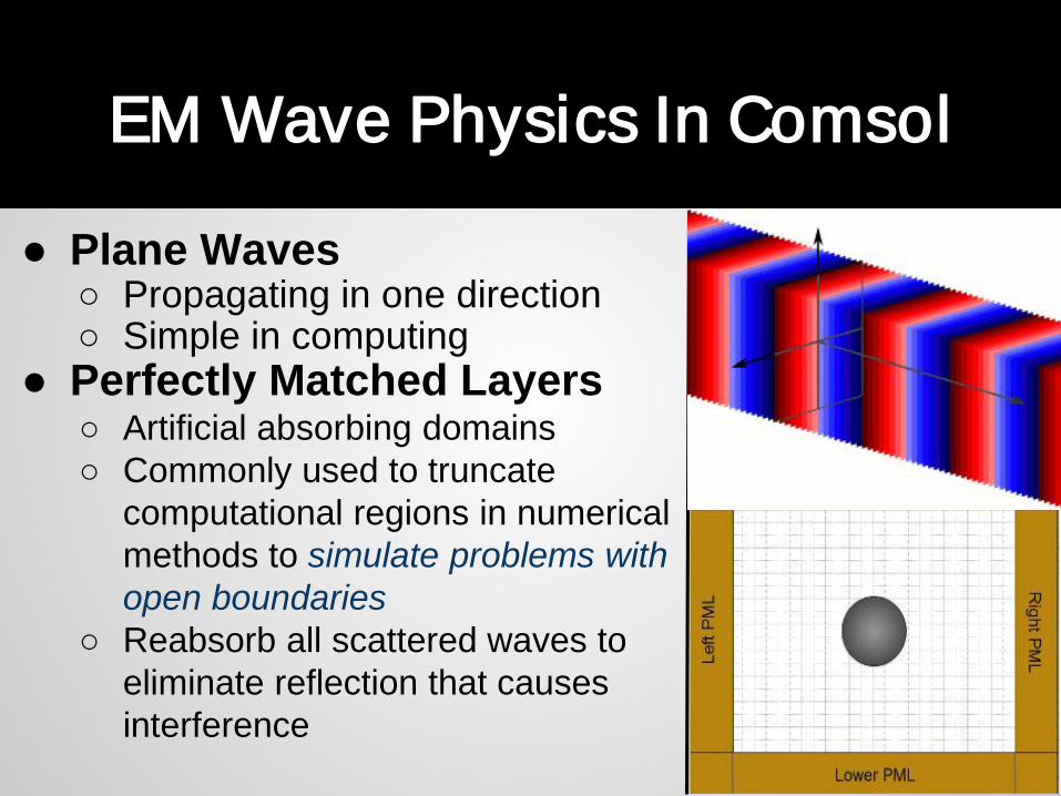
● Plane Waves○ Propagating in one direction○ Simple in computing
● Perfectly Matched Layers○ Artificial absorbing domains○ Commonly used to truncate
computational regions in numerical methods to simulate problems with open boundaries
○ Reabsorb all scattered waves to eliminate reflection that causes interference
EM Wave Physics In Comsol
Plane Waves
Scattering Physics In Comsol
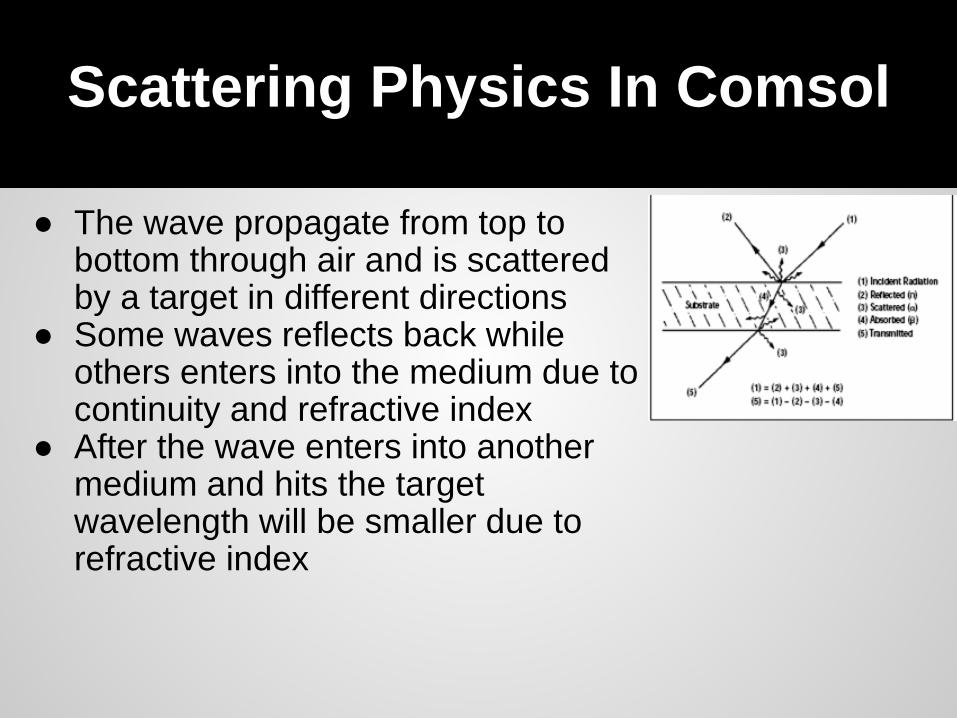
● The wave propagate from top to bottom through air and is scattered by a target in different directions
● Some waves reflects back while others enters into the medium due to continuity and refractive index
● After the wave enters into another medium and hits the target wavelength will be smaller due to refractive index