electromagnetic optimal design and … in electromagnetics research, vol. 105, 445{461, 2010...
TRANSCRIPT

Progress In Electromagnetics Research, Vol. 105, 445–461, 2010
ELECTROMAGNETIC OPTIMAL DESIGN AND PREPA-RATION OF BROADBAND CERAMIC RADOME MATE-RIAL WITH GRADED POROUS STRUCTURE
F. Chen, Q. Shen, and L. Zhang
State Key Laboratory of Advanced Technology for MaterialsSynthesis and ProcessingWuhan University of TechnologyWuhan 430070, China
Abstract—Silicon nitride (Si3N4) ceramic is a promising ultra-highspeed (> 5 mach) broadband (1–18GHz) radome material becauseof its excellent high-temperature resistance, good mechanical anddielectric properties. Si3N4 ceramics with A-sandwich wall structureare successfully applied to passive self-direction high transmissionefficiency broadband radome (1–18GHz). In the present study, anovel graded porous wall structure for broadband radome is promoted.The feasibility of using this structure is carried out by a computeraided design for the wall structure based on the microwave equivalentnetwork method. By optimizing the layer number (n), structuralcoefficient (p), thickness (d) and dielectric constant (ε) of each layer,the power transmission efficiency at 1–18 GHz of graded porous Si3N4
ceramic radome is calculated. Si3N4 ceramics with graded porousstructure are then prepared according to the design. The preparedsample exhibits a good graded porous structure with the porosityrange from ∼ 2% to 63 %. The tested power transmission efficiency at1–18GHz for the obtained sample matches well with the calculationresults, indicating that the graded porous structure is feasible for thebroadband radome application.
1. INTRODUCTION
A radome [1–3] acts as a protective cover to make the antenna insidework safely under abominable environment but does not interfere withits operation. Current missile development programs are endeavoringto increase both the flight speed (known as the Mach number) and thefrequency bandwidth for guide control.
Corresponding author: Q. Shen ([email protected]).

446 Chen, Shen, and Zhang
As shown in Fig. 1, the radome will suffer ultra-high temperature(1500–2000◦C) when the missile flight speed is higher than 5 machbefore hitting the target, which is a huge challenge for the radomematerial. As latest reported [4], silicon nitride (Si3N4) ceramic is thebest candidate for the high speed radome application. Si3N4 has beenused in numerous applications because of its superior properties, suchas elevated high-temperature strength, good oxidation resistance andlow thermal expansion coefficient [5–7]. Si3N4 has strong covalentchemical bond and two forms, α and β phases. Nowadays, variousprocessing techniques have been developed to prepare both the porousand dense Si3N4 ceramics for structural and functional applications [8–12].
Figure 1. Missile flight speed as a function of the radome surfacetemperature and flight height.
`
Thin wall
Bro
adban
d
Half-wave wall
A-Sandwich
B-Sandwich
C-Sandwich
Multilayer
Graded
Figure 2. Schematic map of the radome wall structure.

Progress In Electromagnetics Research, Vol. 105, 2010 447
The defined frequencies are often used for active or half-active self-direction missile system, while the broadband (such as 1 ∼ 18GHz)wave transmission efficient is often used for passive self-directionmissile application, which is greatly determined by the radome wallstructure [13, 14], as shown in Fig. 2. The traditional using half-wavewall structure is just for the defined frequency application [15]. Themost commonly used and reported broadband radome wall structureincludes A-sandwich, C-sandwich and multilayer. However, thesestructures are not suitable for high temperature environment, due tothe big mismatch of the thermal properties of each layer (namelythe ultra-high residual thermal stress), which may restrain theirapplication in the high speed missile radome. Functionally gradedmaterials (FGMs) have been developed early in the 1990s [16] and areconsidered to be one of the best structures to relax the thermal stressbetween layers, which are specially designed for ultra-high temperatureapplication. Thus, we report on a novel structure, graded structure, forbroadband and high speed passive self-direction radome application.Up to date, the graded porous structure with dense and porous layershas not been reported in the broadband radome application.
The purpose of this study is to investigate the feasibility of thegraded porous structure for the broadband radome application bytransmission efficiency calculation followed by optimizing the layernumber (n), structural coefficient (p), thickness (d) and dielectricconstant (ε) of each layer, and to explore the processing method forpreparation of Si3N4 ceramics with graded porous structure. Finally,the transmission efficiency of the radome panel with graded porousstructure is tested and compared with the numerical results.
2. OPTIMAL DESIGNS FOR THE RADOME WALLSTRUCTURE
2.1. Hypotheses
Before designing a radome by calculating the transmission efficiency inan effective way, some hypotheses are made as follows:
(1) Plane wave solutions are used in mathematical descriptions ofwave propagation in order to synthesis more complicated wavefronts.A plane wave is a mathematical but useful idealization because atlarge distances from sources and over regions of restricted size, curvedwavefronts can be described approximately by plane wave functions.
(2) The theory of plane wave propagation through a planedielectric sheet is used for radome design because a curved radomecan be approximated as local plane. Thus, this paper studiespropagation through flat sheets only. The flat sheet is a practically

448 Chen, Shen, and Zhang
useful and instructive boundary value problem, which demonstratesquantitatively how wave propagation depends on the dielectricconstant and thickness of the sheet as well as the wave frequency,polarization, and incidence angle of the wave.
(3) A linearly polarized wave with the polarization either parallelor perpendicular to the plane of incidence is considered and thecalculation methods for the complex valued transmission efficiencyof a homogeneous, isotropic, nonmagnetic and dielectric sheet aredevelopped.
2.2. Calculation Model
Over the past few decades, several simulation methods for broadbandelectromagnetic wave penetration property have been developed,including the basic electromagnetic wave theory, finite elementalanalysis, transmission line method, etc [17–19]. For single layerstructure, it is easy to calculate the wave transmission properties asdescribed by Ref. [20]. For multilayer structure, such as A-sandwich(three layers), C-sandwich (five layers), etc., the calculation becomescomplicated and it is difficult to calculate the transmission efficiencydirectly when the layer number is greater than five [21]. In the presentstudy, a microwave equivalent network method is adopted to simplifythe calculation for the graded porous structure. The calculation model
(a)
(b)
Figure 3. The calculation model of graded porous wall structureradome: (a) mathmatical model; (b) equivalent network model.

Progress In Electromagnetics Research, Vol. 105, 2010 449
Figure 4. The dielectric constant (ε) of each layer as a function of therelative thickness (x) and structural coefficient (p) for graded porousstructure.
of graded porous radome wall structure is shown in Fig. 3. Thegraded porous radome wall structure is divided into n layers withequal thickness and the thickness of each layer is d/n (d is the wallthickness). The top and the bottom layers stand for the outer andinner layer of the radome respectively. As a result, from the top to thebottom, porosity increases gradedly from 0 (fully dense) to the highestvalue, while the dielectric constant decreases from the highest value ε1
to the lowest value εn. Thus, the dielectric constant of each layer canbe expressed by Eq. (1).
ε = εn + (ε1 − εn)(1− (x)1/p) (1)
where x is the relative thickness, and p is the structural coefficientof the graded porous radome material. The dielectric constant (ε) ofeach layer as a function of the relative thickness (x) and structuralcoefficient (p) is calculated and shown in Fig. 4. It is illustrated inFig. 4 that the greater the p is, the higher the relative thickness oflayer containing the low dielectric constant material is, which is severeto the mechanical reliability for the radome. As a result, a low p valueis expected in the design for the broadband radome. And p = 4 isselected as the initial condition for the following calculation.
Figure 3(b) is the microwave equivalent network map for the modelshown in Fig. 3(a). Thus, it is easy to calculate the transmissionefficiency by using the fundamental matrix of the transmission line

450 Chen, Shen, and Zhang
model, which is expressed by Eq. (2).[A BC D
]=
[cosk1d1 jZ1
Z0sink1d1
j Z0Z1
sink1d1 cosk1d1
]·[
cosk2d2 j Z2Z0
sink2d2
j Z0Z2
sink2d2 cosk2d2
]
. . .
[coskndn jZn
Z0sinkndn
j Z0Zn
sin kndn coskndn
](2)
where kn = 2πλ0
√ε̇n − sin2 θ0, ε̇n = εn(1 − jtgδn), and d is the wall
thickness, λ0 is the incident wavelength, and θ0 is the incidence angle,Z is the electromagnetic wave impedance.
The calculation of Z for perpendicular polarization is given byEq. (3).
Zn
Z0=
√ε̇n − sin2 θ0
ε̇n cos θ0(3)
while calculation of Z for parallel polarization is given by Eq. (4).
Zn
Z0=
cos θ0√ε̇n − sin2 θ0
(4)
From Eqs. (3) and (4), it is clearly seen that when θ0 = 0, The Zof perpendicular polarization is equal to that of parallel polarization.In order to simplify the calculation, we use θ0 = 0 in the followingcalculations and materials power transmission efficiency test.
The power transmission efficiency is |T |2, where T is given byEq. (5).
T =2
A + B + C + D(5)
3. NUMERICAL RESULTS AND DISCUSSION
For the calculation of power transmission efficiency of graded porousstructure, the effect of layer number (n), structural coefficient (p), wallthickness (d), dielectric constant of inner layer (εn) and outer layer (εn)should be taken into consideration. Based on the Si3N4 ceramic whichis selected as the radome material in the present paper, the dielectricconstant of as-prepared dense Si3N4 ceramic is ∼ 8, while dielectricconstant of the as-prepared porous Si3N4 ceramic with highest porosityis ∼ 2. Meanwhile, Si3N4 ceramic radome wall thickness is evaluatedin Ref. [22], based on their design results, wall thickness of d = 6 mmis selected.
Progress In Electromagnetics Research, Vol. 105, 2010 451
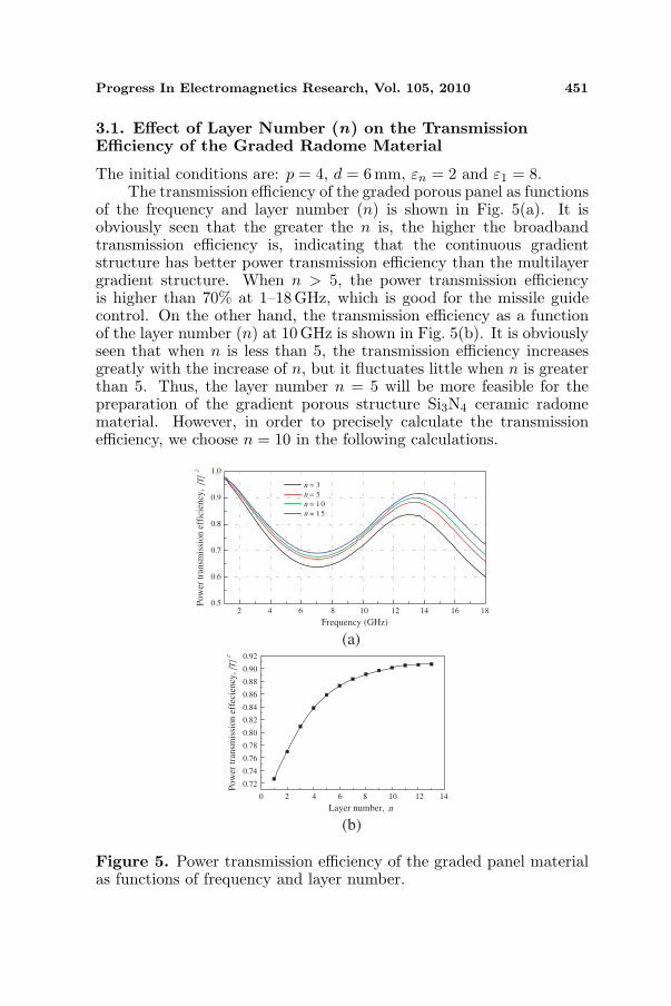
3.1. Effect of Layer Number (n) on the TransmissionEfficiency of the Graded Radome Material
The initial conditions are: p = 4, d = 6 mm, εn = 2 and ε1 = 8.The transmission efficiency of the graded porous panel as functions
of the frequency and layer number (n) is shown in Fig. 5(a). It isobviously seen that the greater the n is, the higher the broadbandtransmission efficiency is, indicating that the continuous gradientstructure has better power transmission efficiency than the multilayergradient structure. When n > 5, the power transmission efficiencyis higher than 70% at 1–18 GHz, which is good for the missile guidecontrol. On the other hand, the transmission efficiency as a functionof the layer number (n) at 10 GHz is shown in Fig. 5(b). It is obviouslyseen that when n is less than 5, the transmission efficiency increasesgreatly with the increase of n, but it fluctuates little when n is greaterthan 5. Thus, the layer number n = 5 will be more feasible for thepreparation of the gradient porous structure Si3N4 ceramic radomematerial. However, in order to precisely calculate the transmissionefficiency, we choose n = 10 in the following calculations.
0.5
0.6
0.7
0.8
0.9
1.0
Po
wer
tra
nsm
issi
on
eff
icie
ncy
, |T
|2
Frequency (GHz)
n = 3n = 5n = 10n = 15
(a)
0.72
0.74
0.76
0.78
0.80
0.82
0.84
0.86
0.88
0.90
0.92
Po
wer
tra
nsm
issi
on
eff
ecie
ncy
, |T
|2
Layer number, n
(b)
2 4 6 8 10 12 14 16 18
2 4 6 8 10 12 140
Figure 5. Power transmission efficiency of the graded panel materialas functions of frequency and layer number.

452 Chen, Shen, and Zhang
2 4 6 8 10 12 14 16 180.0
0.1
0.2
0.3
0.4
0.5
0.6
0.7
0.8
0.9
1.0
Po
wer
tra
nsm
issi
on
eff
icie
ncy
, |T
|2
Frequency (GHz)
p = 0.2p = 0.6p = 1p = 2p = 4p = 10p = 100
Figure 6. Power transmission efficiency of the graded panel materialas functions of frequency and structural coefficient.
3.2. Effect of Structural Coefficient (p) on the TransmissionEfficiency of the Graded Radome Material
The initial conditions are: n = 10, d = 6 mm, εn = 2 and ε1 = 8.The transmission efficiency of the graded porous panel as functions
of the frequency and structural coefficient (p) is shown in Fig. 6.According to Fig. 6, it is seen that the greater the p is, the higherthe broadband transmission efficiency is. It is also observed that pplays a very important role in the single frequency application. Forexample, at frequency of 10.5GHz, p = 0.2 is the best choice withtransmission efficiency is close to 100%, while at frequency of 12 GHz,p = 0.6 is the best. As a low p value is expected in the design forthe broadband radome, for broadband application at 1–18GHz, it isseen that the transmission efficiency shows nearly no difference in thefrequency range of 13–18 GHz when p is 4 or higher. Also when p is 4or higher, the transmission efficiency at 1–13 GHz is higher than 70%,which can be practically used. Thus, we choose p = 4 in the followingcalculation and preparation of the graded radome material.
3.3. Effect of Wall Thickness (d) on the TransmissionEfficiency of the Graded Radome Material
The initial conditions are: n = 10, p = 4, εn = 2 and ε1 = 8.The transmission efficiency of the gradient porous panel as
functions of the frequency and wall thickness (d) is shown in Fig. 7.According to Fig. 7, it is seen that when d is less than 10 mm, thetransmission efficiency shows almost no difference, and when d is lessthan 7 mm, the transmission efficiency is higher than 70%, whichfulfills the requirements for the broadband radome application and

Progress In Electromagnetics Research, Vol. 105, 2010 453
has a similar conclusion with Ref. [23]. Specially, if the radomeis used at defined frequency, the thickness can be selected by theapplied frequencies and the mechanical properties. Considering themechanical requirements for the broadband radome, a certain thicknessis needed. As a result, we choose d = 6 mm in the preparation ofSi3N4 gradient ceramic radome material, after considering both thebroadband transmission property and the mechanical property.
3.4. Effect of Dielectric Constant (ε) on the TransmissionEfficiency of the Graded Radome Material
The initial conditions are: n = 10, p = 4, d = 6 mm, εn = 2 andε1 = 8.
2 4 6 8 10 12 14 16 180.0
0.1
0.2
0.3
0.4
0.5
0.6
0.7
0.8
0.9
1.0
Po
wer
tra
nsm
issi
on
eff
icie
ncy
, |T
|2
Frequency (GHz)
d = 4 mmd = 5 mmd = 6 mmd = 7 mmd = 8 mmd = 10 mmd = 15 mm
Figure 7. Power transmission efficiency of the graded panel materialas functions of frequency and wall thickness.
2 4 6 180.5
0.6
0.7
0.8
0.9
1.0
Pow
er t
rans
mis
sion
eff
icie
ncy,
|T
|2
Frequency (GHz)
1 = 5
1 = 6
1 = 7
1 = 8
168 10 12 14
ε
ε
ε
ε
Figure 8. Power transmission efficiency of the graded panel materialas functions of frequency and dielectric constant of outer layer.

454 Chen, Shen, and Zhang
2 4 6 8 1 0 1 2 1 4 1 80.5
0.6
0.7
0.8
0.9
1.0
Po
wer
tra
nsm
issi
on
eff
icie
ncy
, |T
|2
Frequency (GHz)
n = 1
n = 1.5
n = 2
n = 2.5
n = 3
6 1
ε
ε
ε
ε
ε
Figure 9. Transmission efficiency of the porous graded panel asfunctions of frequency and εn.
The transmission efficiency of the graded panel material asfunctions of the frequency and dielectric constant of outer layer (ε1) isshown in Fig. 8. It is obviously seen that the transmission efficiencydecreases with the increase of ε1. Our previous experiment suggestedthat when MgO and AlPO4 are used as the sintering additives, thedielectric constant for the fully dense sample is ∼ 7. In this situation,according to Fig. 8, the transmission efficiency is higher than 75%,which fulfills the requirements for the broadband radome application.
On the other hand, the transmission efficiency of the graded panelmaterial as functions of the frequency and dielectric constant of innerlayer (εn) is shown in Fig. 9. It is obviously seen that the transmissionefficiency decreases with the increase of εn. When εn is less than2.5, the transmission efficiency is higher than 75%, which fulfills therequirements for the broadband radome application.
From the above calculations, the as-designed conditions for thepreparation of the Si3N4 broadband ceramic radome material are:n = 5, p = 4, d = 6mm, εn < 2.5 and ε1 < 8.
4. EXPERIMENTAL PROCEDURES
Considering the optimal design results, according to our experimentalprogress in the past years, the material used for the preparation of thegraded porous Si3N4 ceramic has been selected. Firstly, Si3N4 ceramicswith nearly fully dense have been prepared by using MgO and AlPO4
as the sintering additive and spark plasma sintering technique, thedielectric constant of which is ∼ 7.0 [24]. This material has actualthe lowest porosity and the maximum dielectric constant, and is usedas the “top” layer for the preparation of the graded porous Si3N4

Progress In Electromagnetics Research, Vol. 105, 2010 455
0.0 0.2 0.4 0 .6 0.8 1.02
3
4
5
6
7
layer 5layer 4
layer 3
layer 1
layer 2
p = 4
Die
lect
ric
con
stan
t, ε
Relative thickness, x
ε = ε + (ε − ε ) (1 − (x) )n1/p
1 n
Figure 10. The dielectric constant of each layer for a 5 layers gradedporous ceramic design when ε1 = 7 and εn = 2.2.
ceramics. Secondly, several methods have been applied to prepareSi3N4 porous ceramics with high porosity and low dielectric constant.The sample using 50 vol.% H3PO4 as the pore-forming agent is testedto have the highest porosity (∼ 63%) and the lowest dielectric constant(εn = 2.2) [25]. Thus, in terms of Eq. (1), for 5 layers porous gradedceramics, the dielectric constant of each layer when p = 4 is shown inFig. 10. As a result, the dielectric constant for the other three layerscan be calculated for the experimental design.
The raw materials used in the present study are as follows:commercial fine Si3N4 powder whose particle shape is sphere, averagegrain size is ∼ 0.5µm and the content of α phase is higher than 93%;commercial zirconia (ZrO2) powder whose grain size is ∼ 0.5µm andthe purity is up to 99.9%; commercial magnesia (MgO) and aluminaphosphate (AlPO4) powder whose grain size is < 0.2µm and thepurity was up to 99.9% and phosphorus acid (H3PO4) liquid whoseconcentration is 85% and the purity is up to 99.9%.
Graded porous Si3N4 ceramic with 5 layers is prepared by stackingorderly the 5 individual prepared Si3N4 ceramics, using a phosphatebinder by thermally treated at 200◦C. The preparation method for thedense and porous Si3N4 ceramics have been published and presented indetail in the Refs. [24–26]. The physical properties and the compositionof each layer of porous graded Si3N4 ceramics are listed in Table 1.
After sintering, the microstructure of the fractured surfacesis observed by scanning electron microscopy (SEM). The dielectricconstant and dielectric loss of bulk samples is tested at frequency of

456 Chen, Shen, and Zhang
Table 1. Composition and physical properties of each layer of thegraded porous Si3N4 ceramics.
N Composition and preparation methodd
(mm)
Porosity
(%)ε tgδ
1Si3N4 +4 wt.% MgO+16 wt.% AlPO4
(Spark plasma sintering, 1400◦C, 5min)1.2 < 2 7.0 0.006
2Si3N4 +20 wt.% ZrP2O7
(Pressureless sintering, 1000◦C, 2 h)1.2 ∼ 40 3.8 0.006
3Si3N4 +35 vol.% H3PO4
(Pressureless sintering, 1000◦C, 2 h)1.2 ∼ 46 3.0 0.005
4Si3N4 +40 vol.% H3PO4
(Pressureless sintering, 1000◦C, 2 h)1.2 ∼ 55 2.5 0.006
5Si3N4 +50 vol.% H3PO4
(Pressureless sintering, 1000◦C, 2 h)1.2 ∼ 63 2.2 0.002
10GHz, according to method reported in [27]. The power transmissionefficiency of the graded panel sheet with the size of 100 × 100 mm istested by free space transmission method in a dark microwave room,which is similar to the method in Refs. [28, 29]. It consists of a networkanalyzer where the incident and transmission ports are connected totwo horn antennas located on each side of the test panel. The testincludes two steps: firstly, data (1) are collected without the ceramicradome panel; then, data (2) are collected when the ceramic radomepanel is set. And the transmission efficient is calculated by using data(1) and (2). For broadband transmission efficient test, we have tochange the antenna for several times, according to different frequenciesused. The test frequency is 1–18 GHz.
5. EXPERIMENTAL RESULTS AND DISCUSSION
SEM image of the obtained Si3N4 ceramic with graded porous structureis illustrated in Fig. 11. From this image, it is observed obviouslythat the pores are increased gradually from layer 1 to layer 5,indicating that an expected graded porous structure Si3N4 ceramic issuccessfully prepared by the present technique. On the other hand,the pore size can be well controlled and increased gradually fromless than 0.5µm to several µm, suggesting that the obtained gradedporous Si3N4 ceramic may have promising mechanical and thermalmatching property. Generally, a large amount of fine and uniform open

Progress In Electromagnetics Research, Vol. 105, 2010 457
micropores are observed from layer 2 to layer 5. Moreover, the Si3N4
grains are fine and maintained almost the same particle size of theraw Si3N4 powder. For each individual layer, it is isotropic structure,and the anisotropic effect for each individual layer is considered tobe very limited. As a result, the obtained Si3N4 ceramic withporous graded structure is quite in agreement with the design modelas shown in Fig. 3. Thus, it is easy to adjust and improve theexperimental conditions to prepare the graded structure with variouslayers, porosities (namely dielectric constant), layer thickness, etc.,according to the electromagnetic microwave calculation and design.
Both calculation value and tested value of the power transmissionefficiency of the graded porous structure Si3N4 ceramic radome panelat the incident angle of zero is shown in Fig. 12. It is seen thatthe tested transmission efficiency is higher than 75% at the frequencyrange of 1–18 GHz, indicating that the graded porous structure hasan ideal broadband transmission property. It is feasible to use
Figure 11. SEM image of the obtained Si3N4 ceramic with gradedporous structure.

458 Chen, Shen, and Zhang
2 4 6 8 10 12 14 16 18
0.7
0.8
0.9
1.0
Po
wer
tra
nsm
issi
on
co
effi
cien
cy,
|T|2
Frequency (GHz)
Calculation results
Test results
Figure 12. The calculation value and tested value of powertransmission efficiency of the graded porous structure Si3N4 ceramicradome panel at the incident angle of zero.
the graded porous structure for the broadband radome application.Compared with the calculation results obtained by using the samephysical properties and structural parameters with the experiment,it is clearly seen that the two are nearly in agreement with eachother, suggesting that the electromagnetic microwave transmissioncalculation and optimal design are essential and play a significantrole before the experiment being carried out. The reason forthe differences between the experiment and simulation is that themicrowave equivalent network method used is not accurate enough tobe stand alone tool. Moreover, the effect of temperature and curvatureshape on the transmission efficiency needs further investigation for thegraded porous structure radome application.
6. CONCLUSION
1. Calculation model of graded porous wall structure is established,the microwave equivalent network method is used for transmissionefficiency calculation. When the initial conditions are n = 5, p = 4,d = 6 mm, εn < 2.5 and ε1 < 8, the power transmission efficiencyis higher than 70% at frequency range of 1–18GHz, suggesting thatgraded structure is feasible in broadband radome application.
2. A five layer graded porous Si3N4 ceramic radome material isprepared according to the experimental design.
3. The tested power transmission efficiency of the prepared gradedporous Si3N4 ceramic radome material is higher than 75% at thefrequency range of 1–18 GHz and is in agreement with the calculationresults.

Progress In Electromagnetics Research, Vol. 105, 2010 459
ACKNOWLEDGMENT
This work is supported by the National Natural Science Foundation(Grant 50972111). The authors also wish to gratefully acknowledgethe technical assistance of Prof. Wenyan Yin, Prof. Kai Li at ZhejiangUniversity, P. R. China and Prof. Julie M. Schoenung at University ofCalifornia Davis.
REFERENCES
1. Persson, K., M. Gustafsson, and G. Kristensson, “Reconstructionand visualization of equivalent currents on a radome using anintegral representation formulation,” Progress In ElectromagneticsResearch B, Vol. 20, 65–90, 2008.
2. Sukharevsky, O. I. and V. A. Vasilets, “Scattering of reflector an-tenna with conic dielectric radome,” Progress In ElectromagneticsResearch B, Vol. 4, 159–169, 2008.
3. Persson, K. and M. Gustafsson, “Reconstruction of equivalentcurrents using a near-field data transformation — With radomeapplications,” Progress In Electromagnetics Research, PIER 54,179–198, 2005.
4. Ceramic Radomes for Tactical Missile Systems, www.ceradyne-thermo.com.
5. Shen, Z. J., Z. Zhao, H. Peng, et al., “Formation of toughinterlockingmicrostructures in silicon nitrideceramics by dynamicripening,” Nature, Vol. 417, 266–269, 2002.
6. Peterson, I. M. and T. Y. Tien, “Effect of the grain boundarythermal expansion coefficient on the fracture toughness in siliconnitride,” J. Am. Ceram. Soc., Vol. 78, No. 9, 2345–2352, 1995.
7. Riley, F. L., “Silicon nitride and related materials,” J. Am. Ceram.Soc., Vol. 83, No. 2, 245–265, 2000.
8. Pyzik, A. J. and D. R. Beaman, “Microstructure and propertiesof self-reinforced silicon nitride,” J. Am. Ceram. Soc., Vol. 76,No. 11, 2737–2744, 1993.
9. Diaz, A., S. Hampshire, J. F. Yang, T. Ohji, and S. Kanzaki,“Comparison of mechanical properties of silicon nitrides withcontrolled porosities produced by different fabrication routes,” J.Am. Ceram. Soc., Vol. 88, No. 3, 698–706, 2005.
10. Shan, S. Y., J. F. Yang, J. Q. Gao, W. H. Zhang, and Z. H. Jin,“Porous silicon nitride ceramics prepared by reduction–nitridationof silica,” J. Am. Ceram. Soc., Vol. 88, No. 9, 2594–2596, 2005.

460 Chen, Shen, and Zhang
11. Kawai, C. and A. Yamakawa, “Effect of porosity and microstruc-ture on the strength of Si3N4: Designed microstructure for highstrength, high thermal shock resistance, and facile machining,” J.Am. Ceram. Soc., Vol. 80, No. 10, 2705–2708, 1997.
12. Lam, D. C. C., F. F. Lange, and A. G. Evans, “Mechanicalproperties of partially dense alumina produced from powdercompacts,” J. Am. Ceram. Soc., Vol. 77, No. 8, 2113–2117, 1994.
13. Nie, X.-C., N. Yuan, L.-W. Li, T. S. Yeo, and Y.-B. Gan,“Fast analysis of electromagnetic transmission through arbitrarilyshaped airborne radomes using precorrected-FFT method,”Progress In Electromagnetics Research, PIER 54, 37–59, 2005.
14. Paris, D. T., “Computer-aided radome analysis,” IEEE Trans.Antennas and Propag., Vol. 18, No. 1, 7–15, January 1970.
15. Gu, J., Y. Fan, Y. H. Zhang, and D. K. Wu, “Novel 3-D half-modeSICC resonator for microwave and millimeter-wave applications,”Journal of Electromagnetic Waves and Applications, Vol. 23, No.11–12, 1429–1439, 2009.
16. Mortensen, A. and S. Suresh, “Functionally graded metalsand metal-ceramic composites. 1. Processing,” Int. Mater. Rev.,Vol. 40, No. 6, 239–265, 1995.
17. Hasar, U. C., O. Simsek, and M. Gulnahar, “Simple procedureto simultaneously evaluate the thickness of and resistive losses intransmission lines from uncalibrated scattering parameter mea-surements,” Journal of Electromagnetic Waves and Applications,Vol. 23, No. 8–9, 999–1010, 2009.
18. Kedar, A. and U. K. Revankar, “Parametric study of flat sandwichmultilayer radome,” Progress In Electromagnetics Research,PIER 66, 253–265, 2006.
19. Kedar, A., K. S. Beenamole, and U. K. Revankar, “Performanceappraisal of active phased array antenna in presence of a multilayerflat sandwich radome,” Progress In Electromagnetics Research,PIER 66, 157–171, 2006.
20. Kong, J. A., Electromagnetic Wave Theory, Wiley-Interscience,May 2008.
21. Fuerholz, P. and A. Murk, “Design of a broadband transitionusing the constant impedance structure approach,” Progress InElectromagnetics Research Letter, Vol. 7, 69–78, 2009.
22. Kozakoff, D. J., Analysis of Radome Enclosed Antennas, ArtechHouse, Norwood, MA, 1997.
23. Sunil, S., K. S. Venu, S. M. Vaitheeswaran, and U. Raveendranath,“A modified expression for determining the wall thickness of

Progress In Electromagnetics Research, Vol. 105, 2010 461
monolithic half-wave radomes,” Microw. Opt. Techn. Lett.,Vol. 30, No. 5, 350–352, 2001.
24. Chen, F., Q. Shen, F. Q. Yan, and L. M. Zhang, “Spark plasmasintering of α-Si3N4 ceramics with MgO-AlPO4 as sinteringadditives,” Mater. Chem. Phys., Vol. 107, 67–71, 2008.
25. Chen, F., Q. Shen, F. Q. Yan, and L. M. Zhang, “Pressurelesssintering of α-Si3N4 porous ceramics using H3PO4 pore-formingagent,” J. Am. Ceram. Soc., Vol. 90, No. 8, 2379–2383, 2007.
26. Chen, F., Q. Shen, F. Q. Yan, and L. M. Zhang, “Preparation ofzirconium pyrophosphate bonded silicon nitride porous ceramics,”Mater. Sci. Technol., Vol. 22, No. 8, 915–918, 2006.
27. Chou, Y. H., M. J. Jeng, Y. H. Lee, and Y. G. Jan,“Measurement of RF PCB dielectric properties and losses,”Progress In Electromagnetics Research Letter, Vol. 4, 139–148,2008.
28. Audone, B., A. Delogu, and P. Morindo, “Radome design andmeasurements,” IEEE Trans. Instrument. Measure., Vol. 37,No. 2, 292–295, 1988.
29. Meng, H. F. and W. B. Dou, “A hybrid method for the analysisof radome-enclosed horn antenna,” Progress In ElectromagneticsResearch, PIER 90, 219–233, 2009.