electricity basics
DESCRIPTION
a simple intro about electricity basicsTRANSCRIPT
1
1Fundamentals of Electricity
Atoms.are.made.up.of.positively.charged.protons.and.negatively.charged.electrons.. In. its. equilibrium. form,. the. negative. and. positive. charges. are.equal..The.electric.charge.is.measured.in.coulombs.and.is.known.as.the.ele-mentary.charge.q
. q = × −1 602 10. 19 C . (1.1)
where.q.is.positive.for.protons.and.negative.for.electrons.The.total.charge.of.any.object.Q.is.the.multiple.of.the.elementary.charge.
q.attained.by.the.object..The.electric.charge.can.be.static.or.dynamic..Static.charge.is.acquired.by.the.object.and.stayed.in.the.object.without.any.motion..The.dynamic.charge.moves.inside.the.object.due.to.external.forces.
The.electric.current.i.is.defined.as.the.amount.of.dynamic.charges.Q.pass-ing.a.given.cross.section.of.a.conductor.during.a.given.time..The.current.is.measured.in.coulombs/second.which.is.amperes:
.i dQ
dt= −
.(1.2)
The.negative.sign. in.Equation.1.2. indicates. that. the.direction.of.current. is.opposite.to.the.direction.of.the.flow.of.electrons..This.is.a.long-established.norm.in.electrical.engineering.
The.charges.acquired.by.an.object.elevate.the.potential.of.the.object..Ohm’s.law.relates.this.potential.to.the.current.inside.the.object.in.a.linear.relationship
. v iz= . (1.3)
wherei.is.the.current.passing.through.the.object;.its.unit.is.ampere.or.Az.is.the.impedance.of.the.object;.its.unit.is.ohm.or.Ωv.is.the.potential.difference.across.the.object;.its.unit.is.volt.or.V
The. voltage. and. current. produce. electromagnetic. field. (EMF). near. the.energized.line..This.EMF.can.reach.a.nearby.metallic.object.and.acts.as.an.invisible. link. between. the. energized. line. and. the. object.. This. property. is.the.basis.for.several.applications.including.transformers,.generators,.motors,.radio.transmission,.cellular.phones,.and.microwave.communications..On.the.
Copyrighted Material - Taylor & Francis
2 Electric Safety
other.hand,.the.EMFs.surrounding.an.energized.power.line.can.elevate.the.voltage.in.nearby.metallic.objects.to.unsafe.level.
The.EMF.is.composed.of.two.fields:.electric.field.(EF).and.magnetic.field.(MF)..The.voltage.of.the.energized.object.produces.EF.and.the.current.pro-duces.MF..The.magnitudes.of.these.fields.are.directly.related.to.the.levels.of.voltage.and.current,.respectively.
1.1 ElectricFields
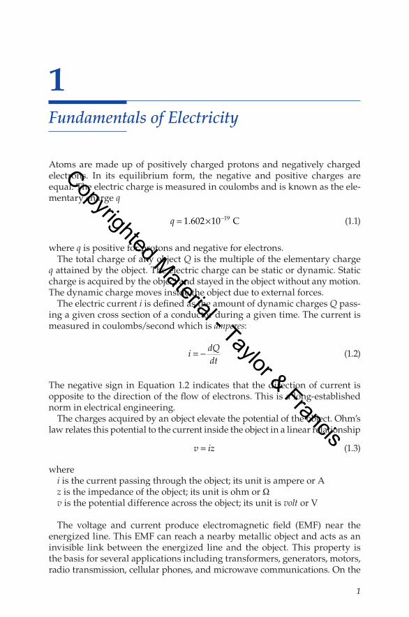
Coulomb’s.law.of.force.states.that.dissimilar.charges.create.forces.that.attract.them,.and.similar.charges.create.forces.that.repel.them,.as.shown.in.Figure.1.1..These.forces.can.be.expressed.by
.F Q Q
d= 1 2
024πε .
(1.4)
whereF.is.the.attraction.or.repulsion.force.in.Newton.(N)d.is.the.distance.between.the.charges.in.meter.(m)Q1.and.Q2.are.the.charges.in.coulombs.(C)ε0.is.a.constant.known.as.absolute.permittivity.(8.85.×.10−12.F/m)
The. force. represents. the. impact. of. one. electric. charge. on. another.. The.direction.of.this.force.forms.the.line.of.force.
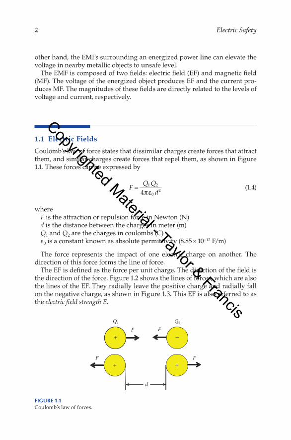
The.EF.is.defined.as.the.force.per.unit.charge..The.direction.of.the.field.is.the.direction.of.the.force..Figure.1.2.shows.the.lines.of.forces,.which.are.also.the.lines.of.the.EF..They.radially.leave.the.positive.charge.and.radially.fall.on.the.negative.charge,.as.shown.in.Figure.1.3..This.EF.is.also.referred.to.as.the.electric field strength E.
+ –F
Q1 Q2F
+ +F F
d
Figure 1.1Coulomb’s.law.of.forces.
Copyrighted Material - Taylor & Francis
3Fundamentals of Electricity
.E F
Q=
.(1.5)
where.the.unit.of.E.is.V/m.The.EF.can.also.be.computed.by.assuming.an.electron.is.placed.in.the.line.
of.force.of.a.charge.Q..In.this.case,.Equation.1.4.can.be.written.as
.F Qq
d=4 0
2πε .(1.6)
whereq.is.the.charge.of.the.electrond.is.the.distance.between.the.charge.Q.and.the.electron
Electric eld
+Q
Figure 1.2Electric.field.lines.of.a.charge.in.space.
Electric field
–Q +Q
Figure 1.3Electric.field.contours.between.two.charges.
Copyrighted Material - Taylor & Francis
4 Electric Safety
The.EF.exerted.on.the.electron.is.the.force.per.its.charge:
.E F
qQd
= =4 0
2πε .(1.7)
At.any.arbitrary.distance.x,.the.EF.is
.E F
qQx
= =4 0
2πε .(1.8)
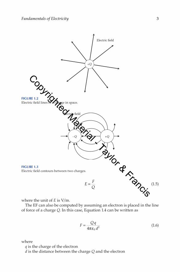
Figure.1.4.shows.a.charge.Q.and.its.EF..If.we.move.around.the.charge.while.maintaining.the.distance.x,.the.EF.is.constant.
The.difference.in.potential.between.the.charge.Q.and.any.arbitrary.point.x.is.defined.as.the.cumulative.effect.of.the.EF.lines.from.the.surface.of.the.charge.to.point.x..In.mathematical.term,.the.potential.difference.is.the.inte-gral.of.the.EF.strength
.
∆v Edxr
x
= ∫.
(1.9)
wherer.is.the.radius.of.the.charge∆v.is.the.potential.difference.between.the.surface.of.the.charge.and.point.x
The.potential.difference.can.then.be.computed.using.Equations.1.8.and.1.9.
.
∆v Qxdx Q
xQ
r xr
x
r
x
= = − = −
∫ 4 4 4
1 10
20 0πε πε πε
.
(1.10)
x
Equipotential surface Electric field
Q
Electron
Δv
Figure 1.4Equipotential.surface.
Copyrighted Material - Taylor & Francis
5Fundamentals of Electricity
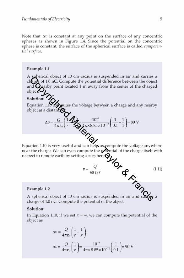
Note. that. ∆v. is. constant. at. any. point. on. the. surface. of. any. concentric.spheres. as. shown. in. Figure. 1.4.. Since. the. potential. on. the. concentric.sphere.is.constant,.the.surface.of.the.spherical.surface.is.called.equipoten-tial surface.
Equation.1.10.is.very.useful.and.can.help.us.compute.the.voltage.anywhere.near.the.charge..We.can.even.compute.the.potential.of.the.charge.itself.with.respect.to.remote.earth.by.setting.x.=.∞;.hence
.v Q
r=4 0πε .
(1.11)
Example1.1
A. spherical. object. of. 10. cm. radius. is. suspended. in. air. and. carries. a.charge.of.1.0.nC..Compute.the.potential.difference.between.the.object.and.a.nearby.point. located.1.m.away.from.the.center.of. the.charged.object.
Solution:
Equation.1.10.computes.the.voltage.between.a.charge.and.any.nearby.object.at.a.distance.x:
∆v Qr x
= −
=× ×
−
=−
−41 1 10
4 8 85 1010 1
11
800
9
12πε π . .V
Example1.2
A. spherical. object. of. 10. cm. radius. is. suspended. in. air. and. carries. a.charge.of.1.0.nC..Compute.the.potential.of.the.object.
Solution:
In.Equation.1.10,.if.we.set.x.=.∞,.we.can.compute.the.potential.of.the.object.as
∆
∆
v Qr x
v Qr
= −
=
=× ×
−
−
41 1
41 10
4 8 85 1010 1
0
0
9
12
πε
πε π . .
= 90 V
Copyrighted Material - Taylor & Francis
6 Electric Safety
1.2 MagneticFields
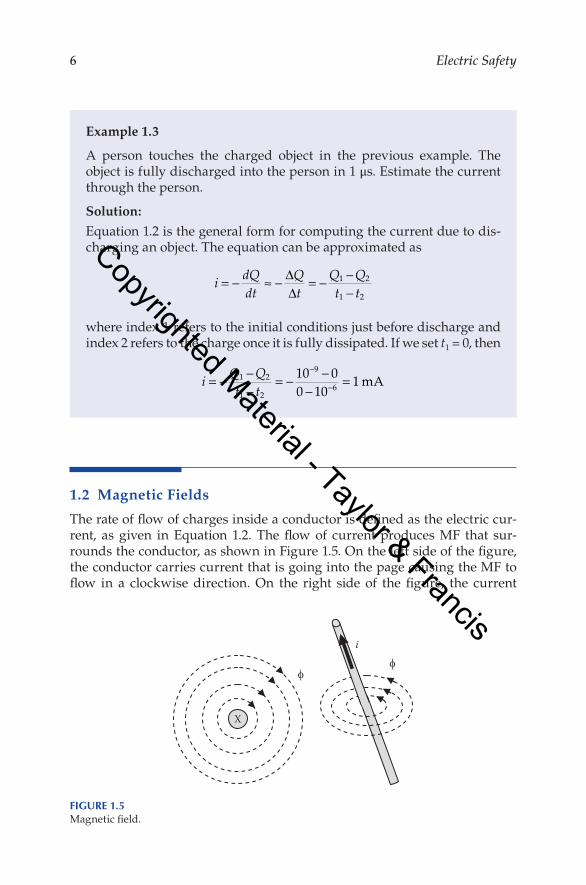
The.rate.of.flow.of.charges.inside.a.conductor.is.defined.as.the.electric.cur-rent,. as. given. in. Equation. 1.2.. The. flow. of. current. produces. MF. that. sur-rounds.the.conductor,.as.shown.in.Figure.1.5..On.the.left.side.of.the.figure,.the.conductor.carries.current.that.is.going.into.the.page.causing.the.MF.to.flow. in. a. clockwise. direction.. On. the. right. side. of. the. figure,. the. current.
Example1.3
A. person. touches. the. charged. object. in. the. previous. example.. The.object.is.fully.discharged.into.the.person.in.1.μs..Estimate.the.current.through.the.person.
Solution:
Equation.1.2.is.the.general.form.for.computing.the.current.due.to.dis-charging.an.object..The.equation.can.be.approximated.as
i dQdt
Qt
Q Qt t
= − ≈ − = − −−
∆∆
1 2
1 2
where.index.1.refers.to.the.initial.conditions.just.before.discharge.and.index.2.refers.to.the.charge.once.it.is.fully.dissipated..If.we.set.t1.=.0,.then
i Q Qt t
= − −−
= − −−
=−
−1 2
1 2
9
610 00 10
1mA
X
i
Figure 1.5Magnetic.field.
Copyrighted Material - Taylor & Francis
7Fundamentals of Electricity
flowing.in.the.conductor.causes.the.MF.to.rotate.counterclockwise..In.both.cases,.the.direction.of.the.current.with.respect.to.the.direction.of.the.MF.is.the.same.
If.the.conductor.is.surrounded.by.air,.the.relationship.between.the.electric.current. and. the. magnetic. flux. is. constant.. This. constant. is. known. as. the.inductance.of.the.conductor
.L
i= φ
.(1.12)
whereϕ. is. the. MF. (flux). surrounding. the. conductor;. its. unit. is. weber. or. volt.
secondi.is.the.current.inside.the.conductorL.is.the.inductance;.its.unit.is.henry.or.ohm.second
The.flux.density.B.is.defined.as.the.flux.that.falls.on.a.given.area:
.B d
dA= φ
.(1.13)
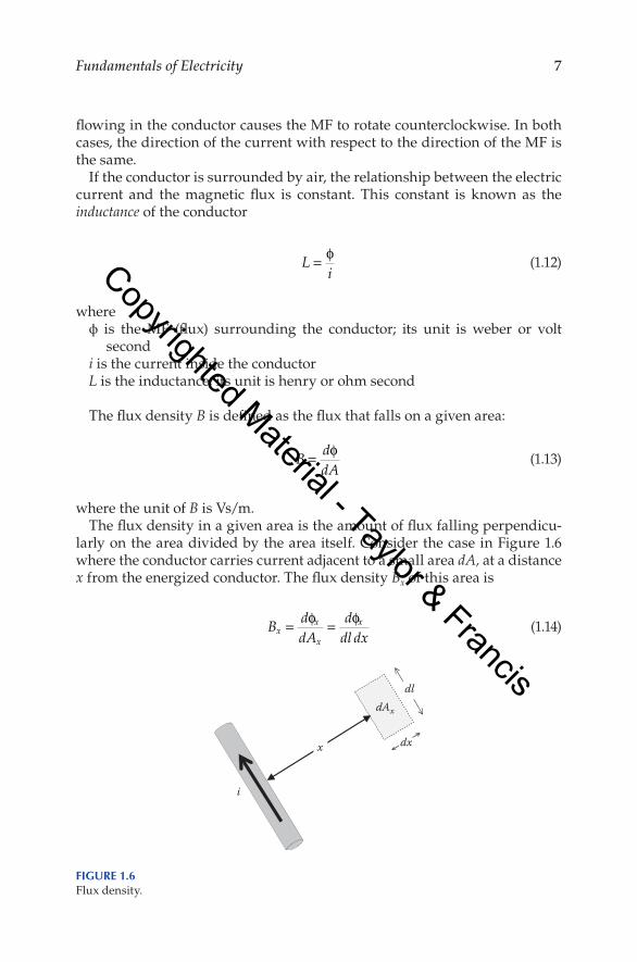
where.the.unit.of.B.is.Vs/m.The.flux.density.in.a.given.area.is.the.amount.of.flux.falling.perpendicu-
larly.on.the.area.divided.by.the.area.itself..Consider.the.case.in.Figure.1.6.where.the.conductor.carries.current.adjacent.to.a.small.area.dA,.at.a.distance.x.from.the.energized.conductor..The.flux.density.Bx.of.this.area.is
.B d
dAddl dxx
x
x
x= =φ φ
.(1.14)
dx
i
x
dldAx
Figure 1.6Flux.density.
Copyrighted Material - Taylor & Francis

8 Electric Safety
whereϕx.is.the.flux.falling.on.the.area.dAx
dl.is.the.length.of.the.areadx.is.the.width.of.the.area
An. important. variable. often. used. in. MF. analysis. is. the. flux linkage. Λ..The.term.is.used.to.describe.the.flux.ϕ.that.surrounds.an.object..Examine.Figure.1.7..The.figure.shows.an.energized.conductor.and.an.object.nearby..The.flux.linkage.of.the.energized.conductor.ΛC.is.all.the.flux.from.the.sur-face.of.the.conductor.to.an.infinite.distance..The.flux.linkage.of.the.nearby.object.ΛO.is.all.the.flux.that.surrounds.the.object,.which.is.the.flux.from.the.surface.of.the.object.to.infinite.distance.(dashed.circles).
The.flux.linkage.Λ.is.often.computed.per.unit.length.of.the.conductor
.λ = d
dlΛ
.(1.15)
whereλ.is.the.flux.linkage.per.unit.length.(Vs/m)l.is.the.length.of.the.conductor.producing.the.flux
Hence,.Equation.1.14.can.be.rewritten.as
.B d
dxxx= λ
.(1.16)
X
Object
ЛO
ЛC ∞
∞
Energized conductor
Figure 1.7Flux.linkage.
Copyrighted Material - Taylor & Francis
9Fundamentals of Electricity
The.MF.strength.H.is.defined.as
.H Bx
x
r=
µ µ0 .(1.17)
whereμr.is.the.relative.permeability;.its.value.depends.on.the.material.carrying.
the.flux.(for.air,.it.is.equal.to.1)μ0.is.a.constant.known.as.the.absolute.permeability.μ0.=.4π.×.10−7;.its.unit.is.
henry/m.or.ohm.s/mThe.unit.of.H.is.A/m
The. relationship. between. the. electric. current. and. the. MF. strength. is.described.by.Ampere’s.law:
.i H ds= ∫ .
(1.18)
Ampere’s.law.states.that.the.integral.of.the.EF.strength.around.a.closed.path.is.equal.to.the.current.enclosed.by.the.path..The.path.in.the.Equation.1.18.is.ds..At.a.distance.x.from.the.center.of.the.conductor,.the.path.is.the.circumfer-ence.of.a.circle:
. H x ix( )2π = . (1.19)
Using.Equations.1.16,.1.17,.and.1.19,.we.can.compute.the.flux.linkage.between.any.two.arbitrary.points.a.and.b.in.air:
.
λπab
a
bixdx i b
a= = ×
∫ −µ0 7
22 10 ln
.
(1.20)
The. voltage. between. the. two. arbitrary. points. can. be. computed. using.Equation.1.20:
.v d
dtbadidtab
ab= = ×
−λ 2 10 7 ln.
(1.21)
where.the.unit.of.vab.is.volt/length.of.conductor.(V/m).
Copyrighted Material - Taylor & Francis
10 Electric Safety
1.3 AlternatingCurrent
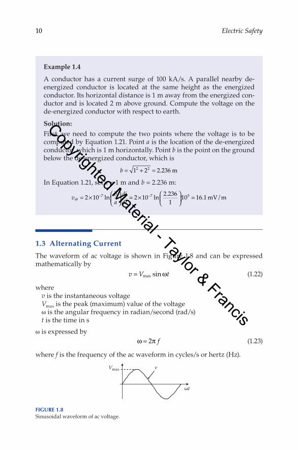
The. waveform. of. ac. voltage. is. shown. in. Figure. 1.8. and. can. be. expressed.mathematically.by
. v V t= max sinω . (1.22)
wherev.is.the.instantaneous.voltageVmax.is.the.peak.(maximum).value.of.the.voltageω.is.the.angular.frequency.in.radian/second.(rad/s)t.is.the.time.in.s
ω.is.expressed.by
. ω π= 2 f . (1.23)
where.f.is.the.frequency.of.the.ac.waveform.in.cycles/s.or.hertz.(Hz).
Example1.4
A. conductor. has. a. current. surge. of. 100. kA/s.. A. parallel. nearby. de-energized. conductor. is. located. at. the. same. height. as. the. energized.conductor..Its.horizontal.distance.is.1.m.away.from.the.energized.con-ductor.and.is.located.2.m.above.ground..Compute.the.voltage.on.the.de-energized.conductor.with.respect.to.earth.
Solution:
First,. we. need. to. compute. the. two. points. where. the. voltage. is. to. be.computed.by.Equation.1.21..Point.a.is.the.location.of.the.de-energized.conductor,.which.is.1.m.horizontally..Point.b.is.the.point.on.the.ground.below.the.de-energized.conductor,.which.is
b = + =1 2 2 2362 2 . m
In.Equation.1.21,.set.a.=.1.m.and.b.=.2.236.m:
v badidtab = ×
= ×
=− −2 10 2 10 2 2361
10 16 17 7 5ln ln . . mV/m
Vmax v
ωt
Figure 1.8Sinusoidal.waveform.of.ac.voltage.
Copyrighted Material - Taylor & Francis
11Fundamentals of Electricity
1.3.1 root Mean Square
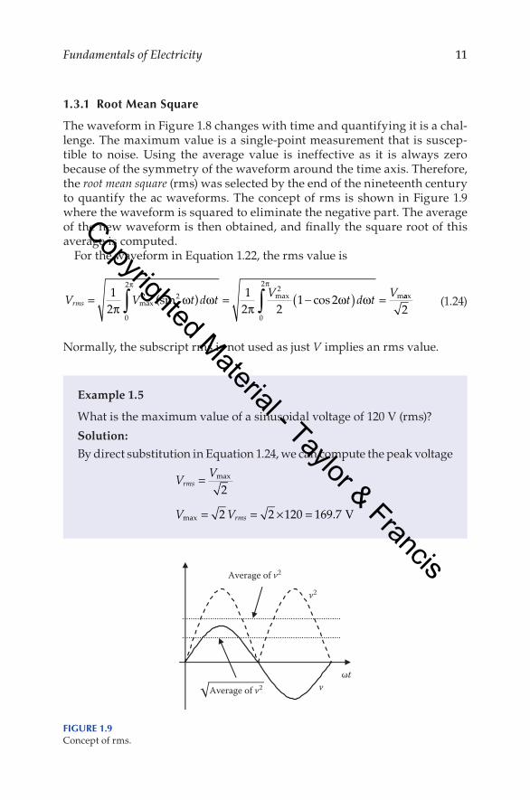
The.waveform.in.Figure.1.8.changes.with.time.and.quantifying.it.is.a.chal-lenge..The.maximum.value.is.a.single-point.measurement.that.is.suscep-tible. to. noise.. Using. the. average. value. is. ineffective. as. it. is. always. zero.because.of.the.symmetry.of.the.waveform.around.the.time.axis..Therefore,.the.root mean square.(rms).was.selected.by.the.end.of.the.nineteenth.century.to.quantify.the.ac.waveforms..The.concept.of.rms.is.shown.in.Figure.1.9.where.the.waveform.is.squared.to.eliminate.the.negative.part..The.average.of.the.new.waveform.is.then.obtained,.and.finally.the.square.root.of.this.average.is.computed.
For.the.waveform.in.Equation.1.22,.the.rms.value.is
V V t d t V t d t Vrms = = −( ) =∫ ∫1
212 2
1 22 2
0
2 2
0
2
πω ω
πω ω
π π
maxmax m(sin ) cos aax
2.
(1.24)
Normally,.the.subscript.rms.is.not.used.as.just.V.implies.an.rms.value.
Example1.5
What.is.the.maximum.value.of.a.sinusoidal.voltage.of.120.V.(rms)?
Solution:
By.direct.substitution.in.Equation.1.24,.we.can.compute.the.peak.voltage
V V
V V
rms
rms
=
= = × =
max
max .
2
2 2 120 169 7 V
v
v2
ωtAverage of v2
Average of v2
Figure 1.9Concept.of.rms.
Copyrighted Material - Taylor & Francis
12 Electric Safety
1.3.2 Phase Shift
If.the.load.in.ac.circuits.is.composed.of.elements.such.as.resistances,.capaci-tances,.and. inductances,. the.phase.shift.angle.of. the.current.θ. is.between.−90°.and.+90°..Figure.1.10.shows.the.current.and.voltage.waveforms.of.an.inductive.load.that.is.composed.of.a.resistance.and.inductance.
The.current.waveform.in.Figure.1.10.can.be.expressed.mathematically.by
. i I t= −max sin( )ω θ . (1.25)
where.θ.is.the.phase.shift.of.the.current.with.respect.to.voltage.
1.3.3 Concept of Phasors
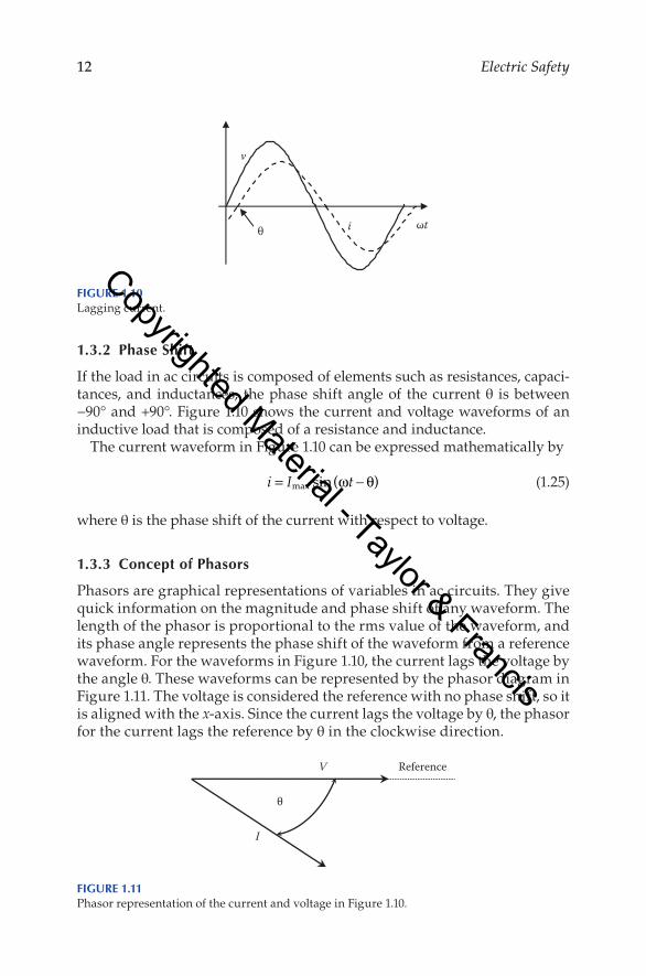
Phasors.are.graphical.representations.of.variables.in.ac.circuits..They.give.quick.information.on.the.magnitude.and.phase.shift.of.any.waveform..The.length.of.the.phasor.is.proportional.to.the.rms.value.of.the.waveform,.and.its.phase.angle.represents.the.phase.shift.of.the.waveform.from.a.reference.waveform..For.the.waveforms.in.Figure.1.10,.the.current.lags.the.voltage.by.the.angle.θ..These.waveforms.can.be.represented.by.the.phasor.diagram.in.Figure.1.11..The.voltage.is.considered.the.reference.with.no.phase.shift,.so.it.is.aligned.with.the.x-axis..Since.the.current.lags.the.voltage.by.θ,.the.phasor.for.the.current.lags.the.reference.by.θ.in.the.clockwise.direction.
v
θ ωti
Figure 1.10Lagging.current.
V
θ
I
Reference
Figure 1.11Phasor.representation.of.the.current.and.voltage.in.Figure.1.10.
Copyrighted Material - Taylor & Francis
13Fundamentals of Electricity
1.3.4 Complex Numbers
Alternating. current. variables. are. analyzed. mathematically. by. using. com-plex.number.computations.where.any.phasor.is.represented.by.a.magnitude.and.an.angle..For.example,.the.voltage.and.current.in.Figure.1.10.or.1.11.can.be.represented.by.the.following.complex.variable.equations
. V V= ∠ °0 . (1.26)
. I I= ∠ − °θ . (1.27)
whereV–.is.the.phasor.representation.of.the.voltage;.it.has.a.bar.on.the.top.indicat-
ing.that.the.variable.is.a.complex.numberV.is.the.magnitude.of.the.voltage.in.rms
The.symbol.∠.is.followed.by.the.angle.of.the.phasor,.which.is.zero.for.volt-age.and.−θ.for.the.lagging.current.
The.complex.forms.in.Equations.1.26.and.1.27.are.called.polar.forms.(also.known.as.trigonometric.forms).
1.4 Three-PhaseSystems
High-power. equipment. such. as. generators,. transformers,. and. transmis-sion.lines.are.built.as.three-phase.equipments..The.three-phase.system.had.been.selected.as.a.standard.for.power.system.equipment.mainly.because.it.
Example1.6
The.voltage.applied.across.a.load.impedance.is.120.V..The.current.pass-ing.through.the.load.is.10.A.and.lags.the.voltage.by.30°..Compute.the.load.impedance.
Solution:
Using.Ohm’s.law,.the.impedance.Z.is.the.voltage.divided.by.the.cur-rent.. The. computation. must. be. performed. using. complex. number.mathematics..We.can.take.the.voltage.as.our.reference;.hence
Z VI
= = ∠ °∠ − °
= ∠ °120 010 30
12 30 Ω
Copyrighted Material - Taylor & Francis
14 Electric Safety
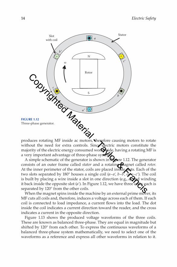
produces.rotating.MF. inside.ac.motors,. therefore.causing.motors. to.rotate.without. the. need. for. extra. controls.. Since. electric. motors. constitute. the.majority.of.the.electric.energy.consumed.worldwide,.having.a.rotating.MF.is.a.very.important.advantage.of.three-phase.systems.
A.simple.schematic.of.the.generator.is.shown.in.Figure.1.12..The.generator.consists.of.an.outer. frame.called.stator. and.a. rotating.magnet.called.rotor..At.the.inner.perimeter.of.the.stator,.coils.are.placed.inside.slots..Each.of.the.two.slots.separated.by.180°.houses.a.single.coil.(a−a′,.b−b′,.or.c−c′)..The.coil.is.built.by.placing.a.wire.inside.a.slot.in.one.direction.(e.g.,.a).and.winding.it.back.inside.the.opposite.slot.(a′)..In.Figure.1.12,.we.have.three.coils;.each.is.separated.by.120°.from.the.other.coils.
When.the.magnet.spins.inside.the.machine.by.an.external.prime.mover,.its.MF.cuts.all.coils.and,.therefore,.induces.a.voltage.across.each.of.them..If.each.coil.is.connected.to.load.impedance,.a.current.flows.into.the.load..The.dot.inside.the.coil.indicates.a.current.direction.toward.the.reader,.and.the.cross.indicates.a.current.in.the.opposite.direction.
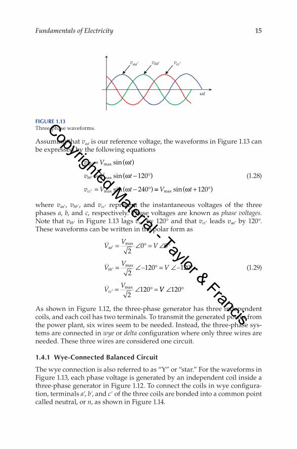
Figure. 1.13. shows. the. produced. voltage. waveforms. of. the. three. coils..These.are.known.as.balanced.three-phase..They.are.equal.in.magnitude.but.shifted.by.120°.from.each.other..To.express.the.continuous.waveforms.of.a.balanced. three-phase.system.mathematically,.we.need. to.select.one.of. the.waveforms.as.a.reference.and.express.all.other.waveforms.in.relation.to.it..
N
+
+
S
+
Stator
Rotor
ω
Slotwith coil a
b
c
c
b
a
Figure 1.12Three-phase.generator.
Copyrighted Material - Taylor & Francis
15Fundamentals of Electricity
Assuming.that.vaa'.is.our.reference.voltage,.the.waveforms.in.Figure.1.13.can.be.expressed.by.the.following.equations
.
v V t
v V t
v V t
aa
bb
cc
′
′
′
=
= − °
= − °
max
max
max
sin( )
sin( )
sin( )
ω
ω
ω
120
240 == + °V tmax sin( )ω 120 .
(1.28)
where. vaa′,. vbb′,. and. vcc′. represent. the. instantaneous. voltages. of. the. three.phases.a,.b,.and.c,.respectively..These.voltages.are.known.as.phase voltages..Note.that.vbb′ . in.Figure.1.13. lags.vaa′.by.120°.and.that.vcc′. leads.vaa′.by.120°..These.waveforms.can.be.written.in.the.polar.form.as
.
V V V
V V V
V V
aa
bb
cc
′
′
′
= ∠ ° = ∠ °
= ∠− ° = ∠− °
= ∠ ° =
max
max
max
20 0
2120 120
2120 VV ∠ °120
.
(1.29)
As.shown.in.Figure.1.12,. the.three-phase.generator.has.three.independent.coils,.and.each.coil.has.two.terminals..To.transmit.the.generated.power.from.the.power.plant,.six.wires.seem.to.be.needed..Instead,.the.three-phase.sys-tems.are.connected.in.wye.or.delta.configuration.where.only.three.wires.are.needed..These.three.wires.are.considered.one.circuit.
1.4.1 Wye-Connected Balanced Circuit
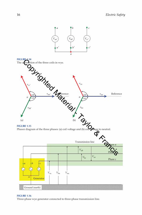
The.wye.connection.is.also.referred.to.as.“Y”.or.“star.”.For.the.waveforms.in.Figure.1.13,.each.phase.voltage.is.generated.by.an.independent.coil.inside.a.three-phase.generator.in.Figure.1.12..To.connect.the.coils.in.wye.configura-tion,.terminals.a′,.b′,.and.c′.of.the.three.coils.are.bonded.into.a.common.point.called.neutral,.or.n,.as.shown.in.Figure.1.14.
ωt
aa bb cc
Figure 1.13Three-phase.waveforms.Copyrighted Material - Taylor & Francis
16 Electric Safety
a b c
n
Vaa Vbb Vcc
a b c
Figure 1.14The.connection.of.the.three.coils.in.wye.
Transmission line
Generator
Phase a
Phase b
Phase cVcaVbc
Vab
VanVbnVcn
Van Vbn
a
n
b c
Vcn
Ground (earth)
Figure 1.16Three-phase.wye.generator.connected.to.three-phase.transmission.line.
Reference Reference120° 120°
120°n n
vcn
vbn
van
120°
(a) (b)
vaa
vbb
vcc
Figure 1.15Phasor.diagram.of.the.three.phases:.(a).coil.voltage.and.(b).coil.voltage.to.neutral.
Copyrighted Material - Taylor & Francis
17Fundamentals of Electricity
The.phasor.diagram.of.the.three-phase.voltages.in.wye.configuration.can.be.obtained.by.grouping.the.three.phasors,.as.shown.in.Figure.1.15a..Since.the.common.point.is.n,.the.phasors.can.be.labeled.V
–an,.V
–bn,.and.V
–cn,.as.shown.
in.Figure.1.15b.The.three.terminals.of.the.wye.connection.(a,.b,.and.c).in.Figure.1.14.are.
connected. to. a. three-wire. transmission. line,. as. shown. in. Figure. 1.16.. The.neutral. point. is. often. connected. to. the. ground.. The. phase. voltage. of. this.system.is.the.voltage.between.any.line.and.the.ground.(or.neutral)..Hence,.for.a.balanced.system
. V V V Vph an bn cn= = = . (1.30)
where.Vph.is.the.magnitude.of.the.phase.voltage..Equation.1.29.can.then.be.rewritten.as
.
V V
V V
V V
an ph
bn ph
cn ph
= ∠ °
= ∠− °
= ∠ °
0
120
120 .
(1.31)
The.voltage.between.any.two.lines.is.known.as.the.line-to-line.voltage..The.line-to-line.voltage.between.a.and.b.is.V
–ab;.it.is.the.potential.of.phase.a.minus.
the.potential.of.phase.b:
.
V V V V V V
V V V V
ab an bn ph ph ph
bc bn cn ph
= − = ∠ ° − ∠ − ° = ∠ °
= − = ∠− °
0 120 3 30
120 −− ∠ ° = ∠ − °
= − = ∠ ° − ∠ ° = ∠ °
V V
V V V V V V
ph ph
ca cn an ph ph ph
120 3 90
120 0 3 150 .
(1.32)
The.line-to-line.voltages.V–
ab,.V–
bc,.and.V–
ca.of.a.balanced.system.are.equal.in.magnitude. and. separated. by. 120°. from. each. other.. The. magnitude. of. the.line-to-line.voltage.is.greater.than.the.phase.voltage.by. 3 .
Example1.7
The.voltage.of.a.Y-connected.three-phase.transmission.line.is.550.kV..Compute.its.phase.voltage.
Solution:
The.voltage.of.any.three-phase.circuit.is.given.as.line-to-line.quantity.Vll..The.phase.voltage,.which.is.also.known.as.line-to-ground.or.phase-to-ground,.is
V Vph
ll= = =3
5503
317 5. kV
Copyrighted Material - Taylor & Francis
18 Electric Safety
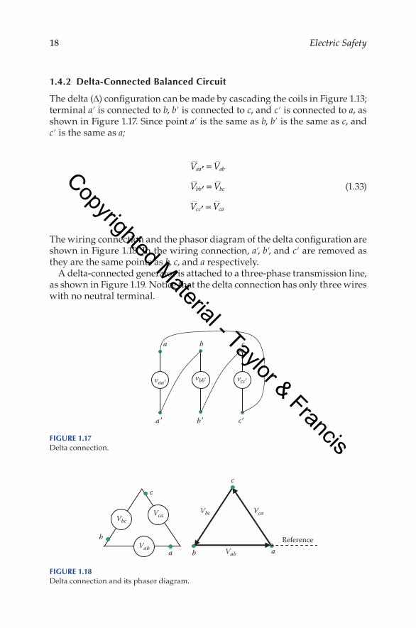
1.4.2 Delta-Connected Balanced Circuit
The.delta.(∆).configuration.can.be.made.by.cascading.the.coils.in.Figure.1.13;.terminal.a′.is.connected.to.b,.b′.is.connected.to.c,.and.c′.is.connected.to.a,.as.shown.in.Figure.1.17..Since.point.a′.is.the.same.as.b,.b′.is.the.same.as.c,.and.c′.is.the.same.as.a;.
.
V V
V V
V V
aa ab
bb bc
cc ca
′
′
′
=
=
= .
(1.33)
The.wiring.connection.and.the.phasor.diagram.of.the.delta.configuration.are.shown.in.Figure.1.18..In.the.wiring.connection,.a′,.b′,.and.c′.are.removed.as.they.are.the.same.points.as.b,.c,.and.a.respectively.
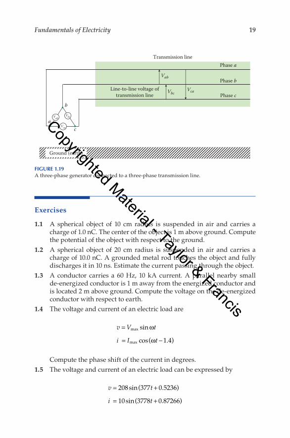
A.delta-connected.generator.is.attached.to.a.three-phase.transmission.line,.as.shown.in.Figure.1.19..Notice.that.the.delta.connection.has.only.three.wires.with.no.neutral.terminal.
a b c
vaa vbb vcc
a b c
Figure 1.17Delta.connection.
c
b
VcaVbc Vca
Vab
Vbc
c
Referencea b a Vab
Figure 1.18Delta.connection.and.its.phasor.diagram.
Copyrighted Material - Taylor & Francis
19Fundamentals of Electricity
Exercises
1.1. A. spherical. object. of. 10. cm. radius. is. suspended. in. air. and. carries. a.charge.of.1.0.nC..The.center.of.the.object.is.1.m.above.ground..Compute.the.potential.of.the.object.with.respect.to.the.ground.
1.2. A. spherical. object. of. 20. cm. radius. is. suspended. in. air. and. carries. a.charge.of.10.0.nC..A.grounded.metal.rod.touches.the.object.and.fully.discharges.it.in.10.ns..Estimate.the.current.passing.through.the.object.
1.3. A. conductor. carries. a. 60. Hz,. 10. kA. current.. A. parallel. nearby. small.de-energized.conductor.is.1.m.away.from.the.energized.conductor.and.is.located.2.m.above.ground..Compute.the.voltage.on.the.de-energized.conductor.with.respect.to.earth.
1.4. The.voltage.and.current.of.an.electric.load.are
v V t
i I t
=
= −
max
max
sin
cos( . )
ω
ω 1 4
. Compute.the.phase.shift.of.the.current.in.degrees.1.5. The.voltage.and.current.of.an.electric.load.can.be.expressed.by
v t
i t
= +
= +
208sin(377 0.5236)
10sin(3778 0.87266)
Phase a
Vab
Vbc
a
Vca
Phase bLine-to-line voltage of
transmission line
Transmission line
c
b
Phase c
Vbc
Vca
Vab
Ground (earth)
Figure 1.19A.three-phase.generator.connected.to.a.three-phase.transmission.line.
Copyrighted Material - Taylor & Francis
20 Electric Safety
. Calculate.the.following:
. a.. The.rms.voltage
. b.. The.frequency.of.the.current
. c.. The.phase.shift.between.current.and.voltage.in.degrees
. d.. The.average.voltage
. e.. The.load.impedance1.6. The.current.and.voltage.of.a.Y-connected.load.are.V
–ab.=.480.∠0°.V,.I–b.=.
20.∠.−130°.A.. a.. Compute.V
–an.
. b.. Compute.I–a.
Copyrighted Material - Taylor & Francis