electrician: construction & maintenance industrial...electrician apprenticeship in-school...
TRANSCRIPT
ApprenticeshipCurriculum Standard
Electrician:Construction & MaintenanceIndustrialDomestic & Rural
Level 1, 2 and 3
Trade Codes: 309A, 309C, 442A
Date: 2003
Please Note: Apprenticeship Training and Curriculum Standards were developed by the Ministry of Training, Colleges and Universities (MTCU). As of April 8th, 2013, the Ontario College of Trades (College) has become responsible for the development and maintenance of these standards. The College is carrying over existing standards without any changes. However, because the Apprenticeship Training and Curriculum Standards documents were developed under either the Trades Qualification and Apprenticeship Act (TQAA) or the Apprenticeship and Certification Act, 1998 (ACA), the definitions contained in these documents may no longer be accurate and may not be reflective of the Ontario College of Trades and Apprenticeship Act, 2009 (OCTAA) as the new trades legislation in the province. The College will update these definitions in the future. Meanwhile, please refer to the College’s website (http://www.collegeoftrades.ca) for the most accurate and up-to-date information about the College. For information on OCTAA and its regulations, please visit: http://www.collegeoftrades.ca/about/legislation-and-regulations
Ontario College of Trades ©
ELECTRICIAN APPRENTICESHIP IN-SCHOOL CURRICULUM
TABLE OF CONTENTS INTRODUCTION ........................................................................................................................................ 4
IMPLEMENTATION .................................................................................................................................. 5
SUMMARY OF HOURS ............................................................................................................................. 6
LEVEL 1: BASIC 1.01 CANADIAN ELECTRICAL CODE ................................................................................. 7
1.02 PRINTS ........................................................................................................................... 10
1.03 ELECTRICAL THEORY ............................................................................................... 12
1.04 INSTALLATION METHODS ......................................................................................... 14
1.05 INSTRUMENTATION ................................................................................................... 16
1.06 ELECTRONICS .............................................................................................................. 19
LEVEL 2: INTERMEDIATE
2.01 CANADIAN ELECTRICAL CODE ............................................................................... 22
2.02 PRINTS ........................................................................................................................... 24
2.03 ELECTRICAL THEORY ............................................................................................... 26
2.04 INSTALLATION METHODS ....................................................................................... 29
2.05 INSTRUMENTATION ................................................................................................... 31
2.06 ELECTRONICS ............................................................................................................. 34
2.07 MONITORING & COMMUNICATION SYSTEMS .................................................... 36
LEVEL 3: ADVANCED
3.01 CANADIAN ELECTRICAL CODE ............................................................................... 39
3.02 PRINTS (CONSTRUCTION AND MAINTENANCE ONLY) ..................................... 41
3.03 ELECTRICAL THEORY ............................................................................................... 43
3.04 INSTALLATION METHODS ........................................................................................ 47
3.05 INSTRUMENTATION .................................................................................................... 50
3.06 FLUID POWER (INDUSTRIAL ONLY) ........................................................................ 53
3.07 ELECTRONICS .............................................................................................................. 57
2
Ontario College of Trades ©
ELECTRICIAN APPRENTICESHIP IN-SCHOOL CURRICULUM
Note: Level one and two courses are common for apprentices registered in both the Construction and Maintenance and Industrial Electrician programs. The third level, Construction and Maintenance apprentices are required to take all courses except 3.06 – Fluid Power. Industrial apprentices are required to take all courses except 3.02 – Prints Level 3.
3
Ontario College of Trades ©
ELECTRICIAN APPRENTICESHIP IN-SCHOOL CURRICULUM
APPRENTICE ELECTRICIAN IN-SCHOOL CURRICULUM INTRODUCTION
This Curriculum Standard has been developed in keeping with the related Ministry of Training, Colleges and Universities (MTCU) Training Standard. The Curriculum Standard provides a standard of theoretical knowledge and practical application to complement the on-the-job experiences of apprentices. The design of the Curriculum Standard facilitates cross-referencing between in-school learning outcomes and related workplace performance objectives as defined in the Training Standard for the trade. Apprentices, therefore, are expected to complete the learning associated with these objectives by applying the prescribed in-school knowledge to the required practical experiences in the work setting. Innovation and the use of complex equipment in trades are resulting in increasing demands for tradespersons who are not only skilled in the practical aspects of the trade, but who also have a sound theoretical knowledge. The objectives of the Curriculum Standard, therefore, are to provide a basis for: a. Sound theoretical training to meet the challenges presented by innovation and increasingly
complex tools and equipment within the work environment. b. Reinforcement of fundamental proficiency in the trade through the practice of work skills as
identified in specific Learning Outcomes. c. Development of a high standard of trade craftsmanship and problem-solving skills. d. Development of a desirable work attitude and a keen sense of responsibility, particularly
concerning public and personal safety. To assure maximum consistency in delivery, a time allocation has been included for each reportable subject, along with a theoretical and practical breakdown of the Learning Content. While setting out content requirements as determined by the Provincial Advisory Committee and the Industry Committee and as prescribed in the Acts and Regulations for the trades, the Curriculum Standard has been designed to give the instructor every reasonable opportunity for flexibility and innovation in curriculum development, lesson planning and delivery. In all practical learning activities, the apprentices will abide by the Occupational Health and Safety Act and all other regulations and policies relating to safety, particularly the use of personal protective equipment. As a general guideline, a time allocation has been included for each respective course and unit. More detailed time allocations for the user have been provided for each topic area to assure consistency in delivery for each student intake.
4
Ontario College of Trades ©
ELECTRICIAN APPRENTICESHIP IN-SCHOOL CURRICULUM
To ensure that successful students will be capable of achieving the Learning Outcomes according to the performance criteria, specific times have been allocated in the respective areas to allow for practical skills development. IMPLEMENTATION Basic September 2003 Intermediate September 2004 Advanced September 2005
5
Ontario College of Trades ©
ELECTRICIAN APPRENTICESHIP IN-SCHOOL CURRICULUM
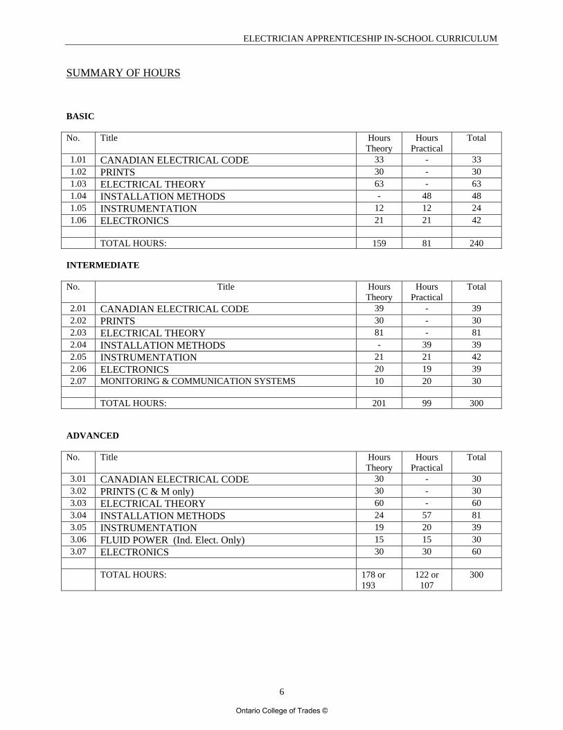
SUMMARY OF HOURS BASIC No. Title Hours
Theory Hours
Practical Total
1.01 CANADIAN ELECTRICAL CODE 33 - 33 1.02 PRINTS 30 - 30 1.03 ELECTRICAL THEORY 63 - 63 1.04 INSTALLATION METHODS - 48 48 1.05 INSTRUMENTATION 12 12 24 1.06 ELECTRONICS 21 21 42
TOTAL HOURS: 159 81 240
INTERMEDIATE No. Title Hours
Theory Hours
Practical Total
2.01 CANADIAN ELECTRICAL CODE 39 - 39 2.02 PRINTS 30 - 30 2.03 ELECTRICAL THEORY 81 - 81 2.04 INSTALLATION METHODS - 39 39 2.05 INSTRUMENTATION 21 21 42 2.06 ELECTRONICS 20 19 39 2.07 MONITORING & COMMUNICATION SYSTEMS 10 20 30
TOTAL HOURS: 201 99 300
ADVANCED No. Title Hours
Theory Hours
Practical Total
3.01 CANADIAN ELECTRICAL CODE 30 - 30 3.02 PRINTS (C & M only) 30 - 30 3.03 ELECTRICAL THEORY 60 - 60 3.04 INSTALLATION METHODS 24 57 81 3.05 INSTRUMENTATION 19 20 39 3.06 FLUID POWER (Ind. Elect. Only) 15 15 30 3.07 ELECTRONICS 30 30 60
TOTAL HOURS: 178 or
193 122 or
107 300
6
Ontario College of Trades ©
ELECTRICIAN APPRENTICESHIP IN-SCHOOL CURRICULUM
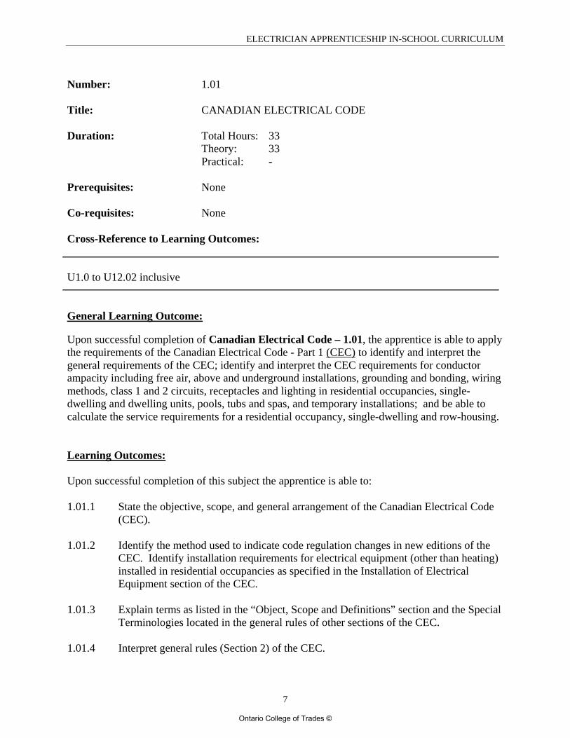
Number: 1.01 Title: CANADIAN ELECTRICAL CODE Duration: Total Hours: 33 Theory: 33 Practical: - Prerequisites: None Co-requisites: None Cross-Reference to Learning Outcomes: U1.0 to U12.02 inclusive General Learning Outcome: Upon successful completion of Canadian Electrical Code – 1.01, the apprentice is able to apply the requirements of the Canadian Electrical Code - Part 1 (CEC) to identify and interpret the general requirements of the CEC; identify and interpret the CEC requirements for conductor ampacity including free air, above and underground installations, grounding and bonding, wiring methods, class 1 and 2 circuits, receptacles and lighting in residential occupancies, single-dwelling and dwelling units, pools, tubs and spas, and temporary installations; and be able to calculate the service requirements for a residential occupancy, single-dwelling and row-housing. Learning Outcomes: Upon successful completion of this subject the apprentice is able to: 1.01.1 State the objective, scope, and general arrangement of the Canadian Electrical Code
(CEC).
1.01.2 Identify the method used to indicate code regulation changes in new editions of the CEC. Identify installation requirements for electrical equipment (other than heating) installed in residential occupancies as specified in the Installation of Electrical Equipment section of the CEC.
1.01.3 Explain terms as listed in the “Object, Scope and Definitions” section and the Special
Terminologies located in the general rules of other sections of the CEC.
1.01.4 Interpret general rules (Section 2) of the CEC.
7
Ontario College of Trades ©
ELECTRICIAN APPRENTICESHIP IN-SCHOOL CURRICULUM
1.01.5 Calculate the size of service equipment for single dwelling units.
1.01.6 Explain the CEC regulations regarding grounding and bonding (Section 10) of electrical systems and circuits operating at 750 volts or less.
1.01.7 Interpret the regulations of the CEC regarding wiring methods (Section 12) for
installations operating at 750 volts or less.
1.01.8 Explain the general regulations regarding Class 1 and Class 2 signal and remote control Circuits (Section 16) of the CEC.
1.01.9 Identify installation requirements for electrical equipment (other than electric
heating) including: lighting, receptacles, heating, and appliances installed in single dwelling occupancies as specified in the Installation of Electrical Equipment Section 26 and 30 of the CEC.
1.01.10 Interpret the CEC regulations regarding the installation of fire alarms located in
dwelling units. 1.01.11 Explain requirements for the installation and wiring of Fixed Electric Surface and
Space Heating Systems located in residential occupancies.
1.01.12 Interpret the CEC regulations for Pools, Tubs, Spas (Section 68).
1.01.13 Identify temporary wiring installation requirements for buildings or projects under construction or demolition (Section 76) of the CEC.
1.01.14 Calculate conduit fill where all conductors are the same size and have the same
insulation type.
1.01.15 Calculate conduit fill where the conductors have different sizes and/or different insulation types.
1.01.16 Calculate raceway fill for the raceway types listed in Section 12 where all conductors
are the same size and have the same insulation type.
1.01.17 Calculate raceway fill for the raceway types listed in Section 12 where the conductors
have different sizes and/or different insulation types.
1.01.18 Calculate the maximum number of conductors sized #14 to #6 that are permitted in a box.
1.01.19 Calculate the minimum size of pull boxes for straight, angle and u-pulls for
conductors larger than #6.
8
Ontario College of Trades ©
ELECTRICIAN APPRENTICESHIP IN-SCHOOL CURRICULUM
1.01.20 Calculate ampacity and apply correction factors for single conductors in free air, including conductors in parallel.
1.01.21 Calculate ampacity and apply correction factors for conductors in a raceway or multi-
conductor cable, including conductors in parallel.
1.01.22 Calculate ampacity and apply correction factors for flexible cords and equipment wires.
1.01.23 Calculate ampacity and apply correction factors for underground conductor
installations using IEEE Standard 835.
Evaluation Structure: Theory Testing 100% Instructional / Delivery Strategies: Lecture Distributed Learning: paper-based; CD ROM; videos
9
Ontario College of Trades ©
ELECTRICIAN APPRENTICESHIP IN-SCHOOL CURRICULUM
Number: 1.02 Title: PRINTS Duration: Total Hours: 30 Theory: 30 Practical: - Prerequisites: None Co-requisites: None Cross-Reference to Learning Outcomes: U 2.01 to U2.07 inclusive. General Learning Outcome: Upon successful completion of Prints – 1.02, the apprentice is able to identify and interpret the alpha numerical lines; use the metric and imperial scales and be able to convert between them; obtain information from architectural, structural and mechanical drawings, specifications, building code and CEC to complete an electrical installation for a single-dwelling; draw and label a panel schematic for a single-dwelling; and complete a material take-off for a single-dwelling. Learning Outcomes: Upon successful completion of this subject the apprentice is able to: 1.02.1 Identify and interpret the alphanumerical lines.
1.02.2 Demonstrate competency with metric scale and imperial scale and be able to convert
between the two.
1.02.3 Read and apply residential specifications.
1.02.4 Use a set of drawings of a single dwelling to apply the information from the architectural, structural and mechanical drawings in relation to an electrical installation.
1.02.5 Draw and label a panel schematic for a single dwelling.
1.02.6 Prepare an electrical material take-off for a single dwelling.
10
Ontario College of Trades ©
ELECTRICIAN APPRENTICESHIP IN-SCHOOL CURRICULUM
1.02.7 Apply specifications, Building and Electrical Codes to single dwellings.
1.02.8 State procedures for inspecting an installation by the appropriate authority.
Evaluation Structure: Theory Testing 50% Project Assessment 50% Instructional / Delivery Strategies: Lecture 100% Distributed Learning: paper-based; CD ROM; videos
11
Ontario College of Trades ©
ELECTRICIAN APPRENTICESHIP IN-SCHOOL CURRICULUM
Number: 1.03 Title: ELECTRICAL THEORY Duration: Total Hours: 63 Theory: 63 Practical: - Prerequisites: None Co-requisites: None Cross-Reference to Learning Outcomes: U5.01 to U 9.04 inclusive. General Learning Outcome: Upon successful completion of Theory – 1.03, the apprentice is able to understand electron theory; define voltage, current and resistance, as well as electrical and mechanical power and energy; describe the effects of electricity on the human body; explain the principles of common sources of Electro-Motive Force (EMF); and to analyze series, parallel and combination DC circuits by applying Ohm’s Law and Kirchoff’s Laws; describe magnetic lines of force and list their characteristics; describe the relationship between magnetism and EMF. Learning Outcomes: Upon successful completion of this subject the apprentice is able to: 1.03.1 Demonstrate an understanding of electron theory.
1.03.2 Describe the requirements for a simple electrical circuit.
1.03.3 Define voltage, current, and resistance. 1.03.4 Define work, power, and energy. 1.03.5 Convert between mechanical and electrical units of work, power, and energy. 1.03.6 Calculate a customer’s residential energy bill using kilowatt-hour units.
1.03.7 Describe the effects of an electrical current on the human body.
12
Ontario College of Trades ©
ELECTRICIAN APPRENTICESHIP IN-SCHOOL CURRICULUM
1.03.8 Apply Ohm’s Law to analyze series DC circuits.
1.03.9 Apply Kirchhoff’s Law to analyze series DC circuits 1.03.10 Apply Ohm’s Law to analyze parallel DC circuits.
1.03.11 Apply Kirchhoff’s Law to analyze parallel DC circuits. 1.03.12 Apply Ohm’s Law to analyze combination DC circuits.
1.03.13 Apply Kirchhoff’s Law to analyze combination DC circuits. 1.03.14 Analyze and calculate current, voltage, and power characteristics in 2-wire and 3-
wire distribution systems for balanced, unbalanced, and faulted conditions. 1.03.15 Define and calculate efficiency of electrical distribution systems.
1.03.16 Perform calculations relating to wire measurements, AWG, SI units, resistively, line
loss, and temperature coefficients. 1.03.17 Name and explain the principles of operation of common sources of EMF. 1.03.18 Describe the characteristics of primary and secondary cells. 1.03.19 State the fundamental law of magnetism. 1.03.20 Define permanent and temporary magnets. 1.03.21 Describe magnetic lines of force and list their characteristics. 1.03.22 Describe the relationship between magnetism and EMF.
Evaluation Structure: Theory Testing 100% Instructional / Delivery Strategies: Lecture Distributed Learning: paper-based; CD ROM; videos
13
Ontario College of Trades ©
ELECTRICIAN APPRENTICESHIP IN-SCHOOL CURRICULUM
Number: 1.04 Title: INSTALLATION METHODS Duration: Total Hours: 48 Theory: - Practical: 48 Prerequisites: None Co-requisites: None Cross-reference to Learning Outcomes: U2.04; U2.05; U2.06; U2.07; U3.01 to U3.08 inclusive; U4.01 to U4.11 inclusive. General Learning Outcome: Upon successful completion of Installation Methods – 1.04, the apprentice is able to demonstrate the operation of common hand and power tools; install common switching devices, outlets and enclosures; correctly terminate conductors; demonstrate the installation procedures for non-metallic sheathed cable, armoured cable, mineral insulated cable, rigid conduits, flexible conduits, liquid-tight conduit, electrical metallic tubing, and electrical non-metallic tubing, including supports and tools required; install a 100 amp. residential consumer’s service and associated branch circuits; layout a service mast installation; install door, signal and extra-low voltage lighting devices; identify and terminate copper communication and hard wired cables. Learning Outcomes: Upon successful completion of this subject the apprentice is able to: 1.04.1 Demonstrate the correct installation procedures and wiring connections for common
residential switching devices and outlets, ensuring strict adherence to CEC and NBC regulations.
1.04.2 Demonstrate the proper installation procedures required for following wiring
methods, while ensuring strict adherence to CEC and NBC regulations: i. Non-metallic sheathed cable
ii. Armoured cable iii. Mineral insulated cable iv. Rigid conduits v. Flexible conduits
vi. Liquid-tight conduit vii. Electrical metallic tubing
14
Ontario College of Trades ©
ELECTRICIAN APPRENTICESHIP IN-SCHOOL CURRICULUM
viii. Electrical Non-metallic tubing
1.04.3 Demonstrate the ability to install a complete 100 amp. residential consumer service including the following circuits:
i. hot water heater ii. range outlet
iii. dryer outlet iv. split duplex receptacles v. GFCI outlets
vi. outside weather-proof receptacles vii. general branch circuits
1.04.4 Prepare a layout drawing for a service mast and indicate the procedure for
installation.
1.04.5 Prepare a circuit drawing and install one or more normally open push buttons to control a signal device.
1.04.6 Prepare a circuit drawing and install an extra low voltage relay to control a 120 volt
light.
1.04.7 Demonstrate the correct method of operation for common hand and power tools used in the electrical trade.
1.04.8 Demonstrate the correct installation method for enclosures and fittings.
1.04.9 Demonstrate the correct installation method for cable, conduit and enclosure
supports.
1.04.10 Demonstrate the correct techniques for the termination of conductors.
1.04.11 Identify and terminate copper communication and hard wired cables for telephones.
Evaluation Structure: Theory Testing 50% Project Assessment 50% Instructional/Delivery Strategies: Lab 100% Distributed Learning: paper-based; CD ROM; videos; demonstrations Number 1.05
15
Ontario College of Trades ©
ELECTRICIAN APPRENTICESHIP IN-SCHOOL CURRICULUM
Title: INSTRUMENTATION Duration: Total Hours: 24 Theory: 12 Practical: 12 Prerequisites: None
Co-requisites: None Cross reference to Learning Outcomes: U11.01 to U11.11 inclusive; U12.01; U12.02. General Learning Outcome: Upon successful completion of Instrumentation – 1.05, the apprentice is able to explain common terms used in instrumentation systems; work with the SI and Imperial system of measurement for pressure and temperature; convert between the four temperature scales; describe the operation, applications and limitations of thermocouples, thermistors, and RTD’s; install, connect, and test thermocouples, thermistors, and RTD’s; identify deformation elements of pressuring measuring equipment; determine the accuracy of pressure measuring equipment; explain relationships between gauge and absolute pressure, and vacuum; explain the operation, construction and applications of typical industrial pressure sensors; Identify ISA instrumentation symbols and draw basic process (P) and Instrumentation (I) diagrams for pressure and temperature devices; explain the operation of light and sound meters. Learning Outcomes: Upon completion of this subject the apprentice is able to: 1.05.1 Define the terminology commonly used to describe Instrumentation systems
including Accuracy, Span, Zero, Repeatability, Dead time, Calibrate, Linearity, Hysteresis, Feedback and Transducer.
1.05.2 Identify ISA instrumentation symbols.
1.05.3 Convert between SI and Imperial pressure scales. 1.05.4 Explain the relationships between gauge pressure, absolute pressure and vacuum.
1.05.5 Identify the various deformation elements used to measure pressure including
Bourdon tubes, bellows, and diaphragm.
16
Ontario College of Trades ©
ELECTRICIAN APPRENTICESHIP IN-SCHOOL CURRICULUM
1.05.6 Explain the theory of operation, construction and application of typical industrial pressure indicators.
1.05.7 Draw basic Process (P) and Instrumentation (I) diagrams for pressure measurement
devices using standard ISA instrumentation symbols.
1.05.8 Connect and determine the accuracy of pressure measuring equipment. 1.05.9 Identify and explain various types of temperature sensing devices including
thermometers, bimetallic, pyrometer.
1.05.10 Convert between the four temperature scales. 1.05.11 Describe the theory of operation, applications and installation methods of
thermocouples as temperature sensors. 1.05.12 Identify the various types of thermocouples and applications of use including J, K,
and T.
1.05.13 Connect, and test thermocouples using a digital voltmeter.
1.05.14 Describe the operation, applications and limitations of RTD temperature sensors.
1.05.15 Connect, and test an RTD using an ohmmeter.
1.05.16 Describe the operation, applications, and limitations of thermistors. 1.05.17 Draw basic Process (P) and Instrumentation (I) diagrams for temperature
measurement devices using standard ISA instrumentation symbols.
1.05.18 Connect and test thermistors using and ohmmeter 1.05.19 Explain the use of light and sound intensity meters
17
Ontario College of Trades ©
ELECTRICIAN APPRENTICESHIP IN-SCHOOL CURRICULUM
Evaluation Structure: Theory Testing 60% Project Assessment 40% Instructional / Delivery Strategies: Lecture 50% Lab 50% Distributed Learning: paper-based; CD ROM; videos; demonstrations
18
Ontario College of Trades ©
ELECTRICIAN APPRENTICESHIP IN-SCHOOL CURRICULUM
Number: 1.06 Title: ELECTRONICS Duration: Total Hours: 42 Theory: 21 Practical: 21 Prerequisites: None Co-requisites: None Cross-Reference to Learning Outcomes: U5.01 to U5.17 inclusive; U7.04; U7.05; U7.09; U7.10; U7.11; U7.12; U7.13; U8.01 to U8.08 inclusive. General Learning Outcome: Upon successful completion of Electronics – 1.06, the apprentice is able to identify schematic symbols for North American and European basic logic gates; describe the operation of basic logic gates; use basic logic gates to create digital logic circuits; state Boolean equations for simple logic gates; design and test combination logic circuits; describe the voltage requirements for TTL and CMOS logic circuits; demonstrate the use of R.S. and D type flip-flop; use a logic probe to troubleshoot a digital circuit; demonstrate procedures for soldering and de-soldering; state the standard resistor colour code; connect resistors in series, parallel and combination circuits; describe the properties of N and P type semiconductor materials; explain current, voltage and biasing requirements for silicon and germanium diodes, and LED’s demonstrate the operation of a bipolar diode; identify the symbols for and describe the operation and biasing for NPN and PNP Bipolar transistors; demonstrate how a transistor can be used as a switch; demonstrate the common applications for an opto-coupler. Learning Outcomes: Upon successful completion of this subject the apprentice is able to: 1.06.1 Describe the voltage requirements for TTL and CMOS logic circuits.
1.06.2 Describe the operation of basic logic gates including NOT, AND, OR, NAND, NOR,
and the exclusive or gates.
1.06.3 Identify the schematic symbols both North American and European for basic logic gates.
19
Ontario College of Trades ©
ELECTRICIAN APPRENTICESHIP IN-SCHOOL CURRICULUM
1.06.4 Demonstrate the use of basic logic gates to create digital logic circuits.
1.06.5 State the Boolean equations for simple logic gates.
1.06.6 Design and test combinational logic circuits using basic logic gates.
1.06.7 State the truth table and demonstrate the use of an R. S. and D type flip-flop.
1.06.8 Demonstrate the use of a logic probe to troubleshoot a digital system.
1.06.9 Demonstrate the proper procedure for soldering and de-soldering.
1.06.10 State the standard resistor colour code.
1.06.11 Connect resistors in series, parallel, and combination circuits, complete with voltmeter and ammeter connections.
1.06.12 Describe the properties of N and P type semiconductor materials.
1.06.13 Describe and demonstrate the operation of the bipolar diode.
1.06.14 State current and voltage requirements for silicon, germanium, and light emitting
diodes (LEDs).
1.06.15 Demonstrate requirements for silicon diodes, germanium diodes and LEDs to be forward and reverse biased.
1.06.16 Explain the important diode characteristics used when selecting replacement diodes.
1.06.17 Describe the operation and basing requirements of NPN and PNP transistors.
1.06.18 Identify the schematic symbols for NPN and PNP bipolar transistors.
1.06.19 Describe and demonstrate how a transistor can be used as a switch.
1.06.20 Describe the operation of an opto-coupler.
1.06.21 State and demonstrate common applications for an opto-coupler.
20
Ontario College of Trades ©

ELECTRICIAN APPRENTICESHIP IN-SCHOOL CURRICULUM
Evaluation Structure: Theory Testing 50% Project Assessment 50% Instructional / Delivery Strategies: Lecture 50% Lab 50% Distributed Learning: paper-based; CD ROM; videos; demonstrations
21
Ontario College of Trades ©
ELECTRICIAN APPRENTICESHIP IN-SCHOOL CURRICULUM
Number: 2.01 Title: CANADIAN ELECTRICAL CODE Duration: Total Hours: 39 Theory: 39 Practical: - Prerequisites: 1.01, 1.02, 1.03, 1.04, 1.05, and 1.06. Co-requisites: None Cross-Reference to Learning Outcomes: U 1.0 to U12.02 inclusive. General Learning Outcome: Upon successful completion of Canadian Electrical Code – 2.01, the apprentice is able to: interpret the CEC requirements pertaining to the installations for: interior and exterior lighting systems; fire alarms and fire pumps, emergency systems, unit equipment and exit signs; fuses, circuit breakers and ground fault protection and control devices; equipment in hazardous locations; hospitals and patient care areas; storage batteries; individual continuous and non-continuous duty service motors; and to calculate conductor and overcurrent device sizes required for specific continuous and non-continuous loads and the minimum ampacity of conductors and overcurrent devices for apartment and similar buildings. Learning Outcomes: Upon successful completion of this subject the apprentice is able to: 2.01.1 Calculate the minimum ampacity of conductors and overcurrent devices for:
Apartment and Similar Buildings Schools Hospitals Hotels, motels, dormitories, and buildings of similar occupancies Other types of occupancies
2.01.2 Interpret the CEC regulations for protection including fuses, circuit breakers and
ground fault protection and control devices including switches, panelboards and solid state devices (Section 14).
22
Ontario College of Trades ©
ELECTRICIAN APPRENTICESHIP IN-SCHOOL CURRICULUM
2.01.3 List and explain the requirements for different classifications of hazardous locations.
2.01.4 Interpret the CEC regulations pertaining to hospitals (Section 24).
2.01.5 Interpret the CEC regulations pertaining to Storage Batteries.
2.01.6 Explain the CEC installation requirements as applicable to branch circuits, overload, and overcurrent protection for individual continuous and non-continuous duty service motors (Section 28).
2.01.7 Interpret the CEC regulations as applicable to interior and exterior lighting equipment
(Section 30).
2.01.8 Interpret CEC regulations governing the installation of optical fibre cables including non-conductive optical fibre, conductive optical fibre and hybrid cables (Section 56); coaxial cables including protection, grounding, indoor, outdoor, overhead and underground installations (Section 54); and communication cables including protection, grounding, indoor, outdoor, overhead and underground installations (Section 60).
Evaluation Structure: Theory Testing 100% Instructional / Delivery Strategies: Lecture Distributed Learning: paper-based; CD ROM; videos
23
Ontario College of Trades ©
ELECTRICIAN APPRENTICESHIP IN-SCHOOL CURRICULUM
Number: 2.02 Title: PRINTS Duration: Total Hours: 30 Theory: 30 Practical: - Prerequisites: 1.01, 1.02, 1.03, 1.04, 1.05, 1.06 Co-requisites: None Cross-Reference to Learning Outcomes: U2.01 to U2.07 inclusive. General Learning Outcome: Upon successful completion of Prints – 2.02, the apprentice is able to: determine utility location and site features using site drawings; determine methods of construction using architectural and structural drawings; determine the electrical characteristics and layout of mechanical equipment and systems; lay out commercial distribution and service equipment and wiring; lay out branch circuit for lighting and equipment; prepare a material take off using drawings, specifications; prepare sketches to solve and document construction problems and solutions; prepare as-built drawings; and develop basic single line, schematic, and wiring diagrams. Learning Outcomes: Upon successful completion of this subject the apprentice is able to: 2.02.1 Determine utility location and site features that affect electrical installations through
the use of site drawings.
2.02.2 Use architectural and structural drawings to determine methods of construction as they affect electrical installation.
2.02.3 Use architectural and structural drawings to determine dimensions and elevations as
they affect electrical installation.
2.02.4 Use mechanical drawings to determine the electrical characteristics of mechanical equipment and systems.
24
Ontario College of Trades ©
ELECTRICIAN APPRENTICESHIP IN-SCHOOL CURRICULUM
2.02.5 Use mechanical drawings to determine the layout of mechanical equipment and systems as they affect electrical installation.
2.02.6 Select the correct wiring methods and electrical equipment for a commercial
installation.
2.02.7 Use a complete set of drawings and specifications to lay out commercial distribution and service equipment and wiring.
2.02.8 Describe common lighting systems and their applications.
2.02.9 Lay out commercial branch circuit wiring, lighting, and equipment using drawings
and specifications.
2.02.10 Use a complete set of drawings, specifications, manufacturers drawings, ULC Standards, the National Building Code and the CEC to lay out a fire alarm system.
2.02.11 Lay out a control system or a communication system as per drawings and
specifications.
2.02.12 Use a complete set of drawings, specifications, manufacturers drawings, and the CEC to prepare a material take off.
2.02.13 Prepare sketches to solve and document construction problems and solutions.
2.02.14 Prepare as-built drawings to document electrical construction.
2.02.15 Read and develop basic single line, schematic, and wiring diagrams.
Evaluation Structure: Theory Testing 50% Project Assessment 50% Instructional / Delivery Strategies: Lecture 100% Distributed Learning: paper-based; CD ROM; videos
25
Ontario College of Trades ©
ELECTRICIAN APPRENTICESHIP IN-SCHOOL CURRICULUM
Number: 2.03 Title: ELECTRICAL THEORY Duration: Total Hours: 81 Theory: 81 Practical: - Prerequisites: 1.01, 1.02, 1.03, 1.04, 1.05, and 1.06 Co-requisites: None C ross-Reference to Learning Outcomes: U5.01 to U 9.04 inclusive. General Learning Outcome: Upon successful completion of Theory – 2.03, the apprentice is able to: describe magnetic flux and flux density; solve problems associated with magnetic energy; explain Ohm’s Law as applied to magnetic circuits; describe factors which affect inductance and perform related calculations; apply Fleming’s hand rules and Lenz’s law; describe the types, construction, operation and characteristics of DC machines; describe a sine wave; calculate RMS, average, maximum, and instantaneous values; calculate frequency, electrical and mechanical degrees; calculate phasors, vectors and vector diagrams; describe the effects of alternating voltage and current in a resistive device; calculate inductive reactance, voltage, current, and power of an inductive circuit; calculate capacitive reactance, voltage, current, power and phase relationships of a capacitive circuit; calculate values for RL/RC/RLC series and parallel circuits; and calculate resonant circuits. Learning Outcomes: Upon successful completion of this subject the apprentice is able to:
2.03.1 Describe magnetic flux and flux density.
2.03.2 Solve problems associated with magnetic energy, including magnetic potential
difference, flux density, reluctance, permeance, and permeability.
2.03.3 List and explain the factors that affect the magnitude and direction of induced EMF
in single conductors and in coils.
26
Ontario College of Trades ©
ELECTRICIAN APPRENTICESHIP IN-SCHOOL CURRICULUM
2.03.4 Describe factors which affect inductance and perform related calculations
2.03.5 State and apply Fleming’s hand rules.
2.03.6 State and apply Lenz’s law. 2.03.7 Describe the creation and effects of eddy currents.
2.03.8 Describe the construction, operation and characteristics of permanent magnet,
separately excited, shunt, series and compound (cumulative and differential) DC motors and generators.
2.03.9 Draw connection diagrams for all types of DC motors and generators. 2.03.10 Describe a sine wave, calculate RMS, average, maximum, and instantaneous values.
2.03.11 Explain and calculate frequency, electrical and mechanical degrees.
2.03.12 Interpret and calculate phasors, vectors and vector diagrams.
2.03.13 Describe the effects of alternating voltage and current in a resistive device.
2.03.14 Describe inductance, self inductance and characteristics of a coil connected to a DC
source.
2.03.15 Describe the characteristics of a coil connected to an AC source.
2.03.16 Calculate inductive reactance, voltage, current, and power of an inductive circuit.
2.03.17 Describe capacitance, and characteristics of a capacitor connected to a DC source.
2.03.18 Describe the characteristics of a capacitor connected to an AC source.
2.03.19 Calculate capacitive reactance, voltage, current, power and phase relationships of a capacitive circuit.
2.03.20 Calculate values for RL/RC/RLC series circuits.
2.03.21 Describe and calculate resonant circuits.
2.03.22 Describe and calculate resonant circuits and phase relations.
2.03.23 Explain and calculate RL/RC parallel circuits.
2.03.24 Label, describe and calculate values for RLC parallel circuit.
27
Ontario College of Trades ©
ELECTRICIAN APPRENTICESHIP IN-SCHOOL CURRICULUM
2.03.25 Describe the method for testing RLC parallel circuits.
2.03.26 Explain and calculate RLC parallel resonant circuits.
2.03.27 Explain and calculate the efficiency of AC loads as related to power factor correction.
2.03.28 Explain the effects of power factor correction.
2.03.29 Calculate power factor correction for single-phase loads.
2.03.30 Describe the principles of operation of various types of single phase transformers.
2.03.31 Determine and perform calculations involving turns/voltage/current ratios for single phase transformers.
Evaluation Structure: Theory Testing 100% Instructional / Delivery Strategies: Lecture Distributed Learning: paper-based; CD ROM; videos
28
Ontario College of Trades ©
ELECTRICIAN APPRENTICESHIP IN-SCHOOL CURRICULUM
Number: 2.04 Title: INSTALLATION METHODS Duration: Total Hours: 39 Theory: - Practical: 39 Prerequisites: 1.01, 1.02, 1.03, 1.04, 1.05, and 1.06. Co-requisites: None Cross reference to Learning Outcomes: U2.04; U2.05; U2.06; U2.07; U3.01 to U3.08 inclusive; U4.01 to U4.11 inclusive. General Learning Outcome: Upon successful completion of Installation Methods – 2.04, the apprentice is able to: Identify the mechanical parts, windings and wiring connections of DC machines; demonstrate manual and magnetic across-the-line starting techniques for motors; demonstrate methods for forward-reverse control of motors; demonstrate reduced voltage starting techniques for DC motors; identify the mechanical parts, windings, and wiring connections for a single- and three-phase squirrel cage induction AC motor (SCIM); demonstrate manual and magnetic across-the-line starting techniques for single- and three-phase squirrel cage motors; demonstrate methods for forward and reverse control of single- and three-phase squirrel cage motors; demonstrate the control of a Single Phase Capacitor Start Dual Voltage Motor with a reversing drum switch, manual starter and a reversing magnetic starter; state the procedures for installing and aligning belt driven motors; and calculate and connect single-phase, 3-wire transformer services. Learning Outcomes: Upon successful completion of this subject the apprentice is able to: 2.04.1 Identify the mechanical parts, windings and wiring connections of DC machines. 2.04.2 Draw schematics and demonstrate wiring, starting, and control methods of series,
shunt and compound DC motors.
2.04.3 Demonstrate methods for forward-reverse control of DC motors.
2.04.4 Explain and demonstrate reduced voltage starting techniques for DC motors.
29
Ontario College of Trades ©
ELECTRICIAN APPRENTICESHIP IN-SCHOOL CURRICULUM
2.04.5 Demonstrate dynamic braking to illustrate principles of Counter Electromotive Force 2.04.6 Use voltmeters and ammeters to determine torque and load characteristics of DC
machines.
2.04.7 Identify the mechanical parts, windings, and wiring connections for single- and three-phase squirrel cage induction motors (SCIM).
2.04.8 Draw schematics and demonstrate manual and magnetic across-the-line starting
techniques for single- and three-phase squirrel cage induction motors. 2.04.9 Draw schematics and demonstrate methods of jogging and plugging control of three-
phase squirrel cage induction motors.
2.04.10 Demonstrate methods for forward and reverse control of single- and three-phase squirrel cage induction motors using push buttons, selector switches, limit switches, pilot lamps, and related devices.
2.04.11 Draw schematic circuit diagrams and demonstrate the control of a Single Phase
Capacitor Start Dual Voltage Motor with a reversing drum switch and manual starter.
2.04.12 Draw schematic circuit diagrams and demonstrate push-button control of a Single Phase Capacitor Start Dual Voltage Motor with a reversing magnetic starter.
2.04.13 Connect, test, and describe the characteristics of RCL circuits.
2.04.14 State the procedures for installing and aligning belt driven motors.
Evaluation Structure: Theory Testing 50% Project Assessment 50% Instructional / Delivery Strategies: Lab 100% Distributed Learning: paper-based; CD ROM; videos; demonstrations
30
Ontario College of Trades ©
ELECTRICIAN APPRENTICESHIP IN-SCHOOL CURRICULUM
Number 2.05 Title: INSTRUMENTATION Duration: Total Hours: 42 Theory: 21 Practical: 21 Prerequisites: 1.01, 1.02, 1.03, 1.04, 1.05, and 1.06.
Co-requisites: None Cross reference to Learning Outcomes: U11.01 to U11.11 inclusive; U12.01; U12.02. General Learning Outcome: Upon successful completion of Instrumentation – 2.05, the apprentice is able to: identify and describe the operation of various level and flow sensing instruments; draw basic process and instrument diagrams using standard ISA instrumentation symbols; explain the operation and applications of typical level and flow measurement devices and transmitters; demonstrate the hydrostatic pressure principle of liquid level measurement; predict with calculations the effect of liquids of different specific gravities on the system; demonstrate the use of the venturi and the orifice plate in flow measurement; and install, connect and test load cells in typical weight measurement applications. Learning Outcomes: Upon successful completion of this subject the apprentice is able to:
2.05.1 Explain the terminology commonly used to describe instrumentation systems
including accuracy, span, zero, repeatability, dead time, calibrate, linearity, hysteresis and transducers.
2.05.2 Describe the concepts of direct and indirect level measurement. 2.05.3 Identify and describe the operation of various level sensing elements including float
switches, point contact, sight glass, capacitance devices, ultrasonic, radiation, and bubblers.
31
Ontario College of Trades ©
ELECTRICIAN APPRENTICESHIP IN-SCHOOL CURRICULUM
2.05.4 Draw basic Process (P) and Instrumentation (I) diagrams for level measurement devices using standard ISA instrumentation symbols.
2.05.5 Determine the output of various level measuring devices. 2.05.6 Connect level measurement devices and test for proper operation. 2.05.7 Explain the concepts of weight, mass, density, and specific gravity. 2.05.8 Describe the concept of hydrostatics and determine the pressure exerted by a column
of fluid by calculation. 2.05.9 Connect and test a system to measure the hydrostatic pressure principle of liquid level
in a column. 2.05.10 Describe the concepts of fluid flow. 2.05.11 Identify and describe the operation of various flow sensing elements including
rotometer, venture, and orifice and magnetic flow meters. 2.05.12 Draw basic Process (P) and Instrumentation (I) diagrams for flow measurement
devices using standard ISA instrumentation symbols. 2.05.13 Determine the output of various flow-measuring devices. 2.05.14 Connect and test flow measurement devices. 2.05.15 Demonstrate the use of the venturi and the orifice plate in flow measurement by
connecting and testing differential pressure transmitters to these devices in typical processes.
2.05.16 Explain the operation and applications of simple voltage and current instrumentation
loops. 2.05.17 Explain the operation and application of transmitters and controllers in
instrumentation control loops.
2.05.18 Install, connect, test, zero, and span an instrumentation control current loop circuit.
2.05.19 Explain the purpose of shielded cable in instrumentation systems and demonstrate the concepts of proper shield grounding techniques.
2.05.20 Explain the theory of operation and the application of intrinsic safety barriers. 2.05.21 Describe the operation of Load cells and their applications.
32
Ontario College of Trades ©
ELECTRICIAN APPRENTICESHIP IN-SCHOOL CURRICULUM
2.05.22 Install, connect and test load cells in typical weight measurement applications.
Evaluation Structure: Theory Testing 60% Project Assessment 40% Instructional / Delivery Strategies: Lecture 40% Lab 60% Distributed Learning: paper-based; CD ROM; videos; demonstrations
33
Ontario College of Trades ©
ELECTRICIAN APPRENTICESHIP IN-SCHOOL CURRICULUM
Number: 2.06 Title: ELECTRONICS Duration: Total Hours: 39 Theory: 20 Practical: 19 Prerequisites: 1.01, 1.02, 1.03, 1.04, 1.05, and 1.06. Co- requisites: None Cross Reference to Learning Outcomes: U5.01 to U5.17 inclusive; U7.04; U7.05; U7.09; U7.10; U7.11; U7.12; U7.13; U8.01 to U8.08 inclusive. General Learning Outcome: Upon successful completion of Electronics – 2.06, the apprentice will have demonstrated the ability to: use an oscilloscope to test circuits; explain the importance of isolation when using test equipment; describe and demonstrate half and full wave rectification; connect capacitors and inductors to filter a power supply output; demonstrate the use of a zener diode as a regulator; demonstrate the operation of an SCR; demonstrate the operation of a DIAC and TRIAC; demonstrate how a DIAC and RC network can be used to phase shift a TRIAC; describe the operation and applications of a pulse transformer; explain the operation of a field effect transistor (FET) and operational amp (Op Amp); calculate the expected gain of inverting and non-inverting OP-Amp circuits; and demonstrate the operation of an Op-Amp used as a comparator and an amplifier. Learning Outcomes: Upon successful completion of this subject the apprentice is able to: 2.06.1 Use an oscilloscope to test circuits.
2.06.2 Explain the importance of isolation as applied to test equipment.
2.06.3 Describe and demonstrate full wave rectification.
2.06.4 Connect capacitors and inductors to filter a power supply output.
2.06.5 Explain and demonstrate the use of a Zener diode as a regulator.
34
Ontario College of Trades ©
ELECTRICIAN APPRENTICESHIP IN-SCHOOL CURRICULUM
2.06.6 Describe and demonstrate the operation of an SCR.
2.06.7 Describe and demonstrate the operation of a DIAC.
2.06.8 Describe and demonstrate the use of a TRIAC.
2.06.9 Describe and Demonstrate how a DIAC and RC network can be used to phase shift a TRIAC.
2.06.10 Describe the operation and applications of a Pulse Transformer and the theory of
pulse triggering thyristors.
2.06.11 Explain the operation of a Field Effect Transistor (FET).
2.06.12 Explain the operation of an Operational Amp (Op Amp).
2.06.13 Calculate the expected gain of inverting and non-inverting OP-Amp circuits.
2.06.14 Demonstrate the operation of an Op-Amp used as a Comparator.
2.06.15 Demonstrate the operation of an Op-Amp used as an amplifier.
Evaluation Structure: Theory Testing 50% Project Assessment 50% Instructional / Delivery Strategies: Lecture 50% Lab 50% Distributed Learning: paper-based; CD ROM; videos; demonstrations
35
Ontario College of Trades ©
ELECTRICIAN APPRENTICESHIP IN-SCHOOL CURRICULUM
Number: 2.07 Title: MONITORING & COMMUNICATION SYSTEMS Duration: Total Hours: 30 Theory: 10 Practical: 20 Prerequisites: 1.01, 1.02, 1.03, 1.04, 1.05, 1.06
Co-requisites: None Cross reference to Learning Outcomes: U10.01 to U10.12 inclusive. General Learning Outcome: Upon successful completion of Monitoring & Communication Systems - 2.07, the apprentice will have demonstrated the ability to: describe the operation, installation, testing and troubleshooting requirements for initiation, signal, ancillary and supervisory circuits and devices, in a single two stage fire alarm system using the NBC, CEC, ULC and manufacturer’s documentation; describe the basic operation of wet and dry sprinkler systems; describe the fire suppression agents, components and systems used in fire suppression systems; describe the methods used to terminate and test fibre optic cables; demonstrate an understanding intrusion systems and devices; describe the wiring and operation of nurse call systems; demonstrate the wiring and operation of nurse call systems; layout and wire common paging and communications systems; describe the operation of institutional clock systems; and describe the operation and installation requirements for common home automation systems. Learning Outcomes: Upon successful completion of this subject the apprentice is able to: 2.07.1 Describe the principles of operation and installation requirements of single stage, two
stage, initiation and supervisory circuits.
2.07.2 Describe the principles of operation and installation requirements for pull stations, detectors, flow switches, bells, speakers, addressable initiating devices and sprinkler supervisory devices.
36
Ontario College of Trades ©

ELECTRICIAN APPRENTICESHIP IN-SCHOOL CURRICULUM
2.07.3 Describe the principles of operation and installation requirements of speaker and ancillary relay circuits, annunciators and emergency phones.
2.07.4 Describe the basic operation of wet and dry sprinkler systems. 2.07.5 Describe the uses and dangers of fire suppression agents, the components and
systems used for their installation in suppression systems. 2.07.6 Describe the principles of operation of institutional clock systems. 2.07.7 List the ULC standard for the installation, inspection, testing and verification of Fire
Alarm Systems. 2.07.8 Use the Canadian Building Code to determine the installation requirements for fire
alarm systems and related equipment.
2.07.9 Demonstrate the installation, troubleshooting and testing of initiation and supervisory circuits and devices including two stage initiator wiring.
2.07.10 Demonstrate the installation, troubleshooting and testing of speaker and ancillary
relay circuits, annunciators and emergency phones.
2.07.11 Demonstrate the installation, operation and testing of alarm panels with respect to lights and lamps, power supplies, overcurrent devices, ground fault indicators, annunciator panels and common trouble functions.
2.07.12 Connect intrusion systems and devices.
2.07.13 Connect the wiring and operation of nurse call systems.
2.07.14 Connect paging and communications systems.
2.07.15 Describe the principles of operation and installation requirements for common home
automation systems.
2.07.16 Describe the methods used to install, terminate, and test fibre optic cables.
37
Ontario College of Trades ©
ELECTRICIAN APPRENTICESHIP IN-SCHOOL CURRICULUM
Evaluation Structure: Theory Testing 50% Project Assessment 50% Instructional / Delivery Strategies: Lecture 50% Projects 50% Distributed Learning: paper-based; CD ROM; videos; demonstrations
38
Ontario College of Trades ©
ELECTRICIAN APPRENTICESHIP IN-SCHOOL CURRICULUM
Number: 3.01 Title: CANADIAN ELECTRICAL CODE Duration: Total Hours: 30 Theory: 30 Practical: - Prerequisites: 2.01, 2.02, 2.03, 2.04, 2.05, 2.06, and 2.07. Co-requisites: None Cross-Reference to Learning Outcomes: U 1.0 to U12.02 inclusive General Learning Outcome: Upon successful completion of Canadian Electrical Code – 3.01, the apprentice is able to: interpret the CEC requirements pertaining to the installations for: two or more continuous and non-continuous duty service motor on a feeder or branch circuit; hermetic refrigerant motor-compressor; power and distribution transformers on a feeder and branch circuit; welders on a feeder and branch circuit; capacitors on a feeder, branch circuit and motor branch circuit; high-voltage installations; overcurrent device selection based on load, interrupting ratings and coordination. Learning Outcomes: Upon successful completion of this subject the apprentice is able to: 3.01.1 Interpret the CEC regulations associated with the installation of two or more
continuous and non-continuous duty service motors on a branch circuit or feeder including conductor size and overcurrent device sizes (Section 28).
3.01.2 Interpret the CEC regulations associated with the installation of a hermetic refrigerant
motor-compressor on a branch circuit including conductor size, overload size and overcurrent device size (Section 28).
3.01.3 Interpret the CEC regulations regarding the installation of reduced voltage starters
including overload size, and overcurrent device size.
3.01.4 Calculate tap conductor sizes for motor and compressor branch circuits.
39
Ontario College of Trades ©
ELECTRICIAN APPRENTICESHIP IN-SCHOOL CURRICULUM
3.01.5 Interpret the CEC regulations associated with the installation of transformers including dry-type and liquid-filled (Section 26).
3.01.6 Calculate minimum conductor size and maximum overcurrent protection for
individual power and distribution transformers including dry-type, liquid-filled, high-voltage and low-voltage on a circuit (Section 26).
3.01.7 Calculate minimum conductor size and maximum overcurrent protection for more
than one power and distribution transformer including dry-type, liquid-filled, high-voltage and low-voltage on a feeder or branch circuit (Section 26).
3.01.8 Interpret the CEC regulations regarding welders (Section 42).
3.01.9 Calculate minimum conductor size and the maximum overcurrent protection for
individual resistance and transformer type welders (Section 42).
3.01.10 Calculate the minimum conductor size and the maximum overcurrent protection for more than one resistance and/or transformer type welder on a circuit (Section 42).
3.01.11 Interpret the CEC regulations for the installation of capacitors (Section 26).
3.01.12 Calculate the minimum conductor size, maximum overcurrent device size and
disconnecting means size for capacitors (Section 26).
3.01.13 Interpret the CEC regulations for placing capacitors in motor circuits (Section 26).
3.01.14 Select overcurrent devices based on voltage, continuous load, and maximum current interrupting ratings as per manufacturer’s specifications, CEC and customer’s requirements.
3.01.15 Interpret the CEC regulations associated with high voltage installations including
wiring methods, grounding and bonding (Section 36).
Evaluation Structure: Theory Testing 100% Instructional / Delivery Strategies: Lecture Distributed Learning: paper-based; CD ROM; videos
40
Ontario College of Trades ©
ELECTRICIAN APPRENTICESHIP IN-SCHOOL CURRICULUM
Number: 3.02 Title: PRINTS (CONSTRUCTION & MAINTENANCE ONLY) Duration: Total Hours: 30 Theory: 30 Practical: - Prerequisites: 2.01, 2.02, 2.03, 2.04, 2.05, 2.06, and 2.07. Co-requisites: None Cross-Reference to Learning Outcomes: U2.01 to U2.07 inclusive. General Learning Outcome: Upon successful completion of Prints – 3.02 (C&M), the apprentice is able to: obtain installation details for a construction project from a complete set of drawings and specifications; develop complex single line, schematic and wiring diagrams; layout single- and three-phase systems for feeder and branch circuits from utility supply to utilization points; calculate pulling stresses on a conductor/cable; layout the grounding and bonding requirements for high-voltage indoor and outdoor substations and vaults; identify precautions for installing stress cones; describe the requirements for terminating shielded and concentric neutral high-voltage cables; and describe the testing methods and safety requirements for testing high-voltage cables. Learning Outcomes: Upon successful completion of this subject the apprentice is able to: 3.02.1 Use architectural, electrical, and mechanical drawings and specifications to determine
installation requirements for a construction project.
3.02.2 Read and develop complex single line, schematic and wiring diagrams. 3.02.3 Identify the standards for IEC, NEMA, and EEMAC rated starters and contactors as
per manufacturer’s specifications.
3.02.4 Use plans to design branch circuit layouts for single phase and three phase systems from panels to the points of utilization, employing load balancing techniques.
41
Ontario College of Trades ©
ELECTRICIAN APPRENTICESHIP IN-SCHOOL CURRICULUM
3.02.5 Complete a cable pulling calculation to determine the stresses on the conductor/cable during installation.
3.02.6 Prepare branch circuit, feeder, and bus duct electrical estimates, using the drawings,
for construction installations, and transfer the information to material order sheets.
3.02.7 Complete an electrical system design from the point of utility supply, emergency supplies and transfers, to a panel board and associated loads including transformers, feeders, bus duct, splitters, disconnects, capacitors and motors, applying Code rules.
3.02.8 Complete the grounding and bonding requirements for a high voltage substation
installation including indoor and outdoor substations and electrical vaults.
3.02.9 State the precautions necessary for the installation of a stress cone.
3.02.10 Describe the preparation and termination of shielded High Voltage cables.
3.02.11 Describe the preparation and termination of concentric neutral High Voltage cables.
3.02.12 Describe the testing methods for high voltage cables and identify all applicable safety requirements.
3.02.13 Select overcurrent devices to ensure proper overcurrent coordination as per
manufacturer’s specifications, CEC and customer’s requirements. Evaluation Structure: Theory Testing 50% Project Assessment 50% Instructional / Delivery Strategies: Lecture 100% Distributed Learning: paper-based; CD ROM; videos; demonstrations
42
Ontario College of Trades ©
ELECTRICIAN APPRENTICESHIP IN-SCHOOL CURRICULUM
Number 3.03 Title ELECTRICAL THEORY Duration: Total Hours: 60 Theory: 60 Practical: - Prerequisites: 2.01, 2.02, 2.03, 2.04, 2.05, 2.06, 2.07 Co-requisites: None Cross – Reference to Learning Outcomes: U5.01 to U 9.04 inclusive. General Learning Outcome: Upon successful completion of Electrical Theory – 3.03, the apprentice is able to: list the advantages of three phase circuits over single phase circuits; state the advantages and disadvantages of three phase Wye and Delta systems; calculate voltage, current, power and power factor for three-phase wye and delta systems, three-phase series and parallel RLC circuits; connect wattmeters, power-factor meters and phase-angle meters in a three-phase system; list different types of transformers and their applications and associated losses; explain the principles of three-phase open delta connections; describe the theory of operation and the synchronizing of alternators; illustrate by calculation the principles for single- and three-phase power conversion; describe the construction, operation and troubleshooting procedures for single- and three-phase AC induction motors; identify connections for multiple voltages and speeds for AC motors; describe the construction, operation and troubleshooting procedures for AC wound rotor motors; describe the construction, operation, power factor correction and troubleshooting procedures for three-phase synchronous motors; state the types of insulation classifications and applications using AC motors; and describe motor specifications and procedures for adjustments and lubrication. Learning Outcomes: Upon successful completion of this subject the apprentice will be able to: 3.03.1 List the advantages of three phase circuits over single phase circuits.
3.03.2 State the advantages and disadvantages of three phase Wye and Delta systems.
3.03.3 Calculate voltage, current and power for three phase Wye and Delta systems with
resistive loads.
43
Ontario College of Trades ©
ELECTRICIAN APPRENTICESHIP IN-SCHOOL CURRICULUM
3.03.4 Calculate voltage, current and power for three phase Wye and Delta systems with series and parallel RLC loads.
3.03.5 Calculate the changes in circuit values as a result of three-phase power factor
correction.
3.03.6 Perform calculations and show connections of wattmeters for three phase systems.
3.03.7 Explain the principles of and show proper connection for power-factor and phase-angle meters.
3.03.8 List the various classifications of transformers and identify applications.
3.03.9 List losses associated with transformers and methods for reduce them.
3.03.10 Describe the methods employed to cool transformers. 3.03.11 Identify and describe safety concerns of transformer cooling mediums.
3.03.12 Describe the safety procedures for taking instrument transformers off line.
3.03.13 Interpret transformer nameplate data. 3.03.14 Calculate voltages and currents for three phase transformers. 3.03.15 Calculate transformed and conducted power for autotransformers.
3.03.16 Perform calculations for the determination of transformer impedances.
3.03.17 Calculate maximum available fault currents at the secondary of a transformer.
3.03.18 Describe procedures for determining transformer polarity, terminal identification,
winding ratio and insulation resistance.
3.03.19 Describe procedures for paralleling transformers and taking one off line.
3.03.20 Describe alternator and transformer connections for various 3-phase systems.
3.03.21 Explain the principles of three phase open delta connections and perform related calculations.
3.03.22 Describe the theory of operation of alternators.
3.03.23 Perform calculations to illustrate principles for single and 3-phase power conversion. 3.03.24 Describe the methods of synchronizing alternators.
44
Ontario College of Trades ©
ELECTRICIAN APPRENTICESHIP IN-SCHOOL CURRICULUM
3.03.25 Describe the construction of three phase squirrel cage induction motors.
3.03.26 Describe the principle of operation of three phase squirrel cage induction motors.
3.03.27 Describe the operating characteristics of three phase squirrel cage induction motors.
3.03.28 Describe troubleshooting procedures for three phase squirrel cage induction motors.
3.03.29 Identify AC motor connections and terminal markings for multiple voltage and speed applications.
3.03.30 Describe the construction of single-phase induction motors.
3.03.31 Describe the principle of operation of single-phase induction motors. 3.03.32 Describe the operating characteristics of single-phase induction motors. 3.03.33 Describe troubleshooting procedures for single-phase induction motors. 3.03.34 Describe the construction of three phase wound rotor induction motors. 3.03.35 Describe the principle of operation of three phase wound rotor induction motors.
3.03.36 Describe the operating characteristics of three phase wound rotor induction motors.
3.03.37 Describe troubleshooting procedures for three phase wound rotor induction motors. 3.03.38 Describe the construction of three phase synchronous motors. 3.03.39 Describe the principle of operation of three phase synchronous motors.
3.03.40 Describe the operating characteristics of three phase synchronous motors.
3.03.41 Describe troubleshooting procedures for three phase synchronous motors.
3.03.42 Describe the operation of synchronous motors in power factor correction and constant
speed applications.
3.03.43 State the types of insulation classification and applications used in AC motors.
3.03.44 Describe: i. brush adjustments
ii. brush selection for wound rotor motors iii. slip ring care iv. bearing specifications and types v. bearing applications
45
Ontario College of Trades ©
ELECTRICIAN APPRENTICESHIP IN-SCHOOL CURRICULUM
vi. bearing lubrication
3.03.45 Interpret motor name plate specification values.
Evaluation Structure: Theory Testing 100% Instructional / Delivery Strategies: Lecture Distributed Learning: paper-based; CD ROM; videos; demonstrations
46
Ontario College of Trades ©
ELECTRICIAN APPRENTICESHIP IN-SCHOOL CURRICULUM
Number: 3.04
Title: INSTALLATION METHODS Duration: Total Hours: 81 Theory: 24 Practical: 57 Prerequisites: 2.01, 2.02, 2.03, 2.04, 2.05, 2.06, 2.07
Co-requisites: None Cross reference to Learning Outcomes: U2.04; U2.05; U2.06; U2.07; U3.01 to U3.08 inclusive; U4.01 to U4.11 inclusive. General Learning Outcomes: Upon successful completion of Installation Methods – 3.04, the apprentice is able to: test transformers to determine polarity, impedance, winding ratio and insulation resistance; connect three-phase transformers in wye and delta configurations; connect three-phase RLC loads to transformers in balanced and unbalanced configurations; connect single- and three-phase auto transformers for reduced voltage motor starting; identify the parts and connections for a three-phase wound rotor motor; describe the effects of differing resistance in the rotor circuit of a wound rotor motor under varying loads; connect a two—speed control circuit for a two-speed squirrel-cage motor. State the functions and applications of a Programmable Logic Controller (PLC); determine language and addressing requirements of a PLC; demonstrate the programming of common relay instructions, timers, counters, mathematic functions, and word comparisons on a PLC; identify methods and hard wiring of PLC’s to equipment; demonstrate methods of testing PLC inputs and outputs; and design programs to operate machines in a required manner using many of the internal functions of a PLC Learning Outcomes: Upon completion of this subject the apprentice is able to: 3.04.1 Perform tests to determine the polarity, impedance, winding ratio and insulation
resistance of transformers. 3.04.2 Connect three-phase transformer systems in wye and delta configurations. 3.04.3 Connect three phase RLC loads to transformers in balanced configurations.
47
Ontario College of Trades ©
ELECTRICIAN APPRENTICESHIP IN-SCHOOL CURRICULUM
3.04.4 Describe and connect single and three-phase autotransformers for reduced voltage motor starting.
3.04.5 Identify the mechanical parts, windings, and wiring connections for three phase
wound rotor induction motors. 3.04.6 Describe and demonstrate the operation of a three phase wound rotor induction motor
and its external control circuits. 3.04.7 Connect and describe the effects of differing resistances in the rotor circuit of a
wound rotor motor under varying loads. 3.04.8 Describe and demonstrate the operation of synchronous motors in power factor
correction and constant speed applications. 3.04.9 Design and connect the controller circuit for a two-speed squirrel cage motor. 3.04.10 Describe the function of a PLC and state its typical applications. 3.04.11 Define and convert between the Binary, Octal, Decimal, and Hexadecimal numbering
systems. 3.04.12 Describe the Binary Coded Decimal numbering system. 3.04.13 Identify the major components of a PLC and describe their operation. 3.04.14 Explain the difference between analogue and discrete inputs and outputs. 3.04.15 Determine the language and addressing requirements of a PLC. 3.04.16 Identify methods of installing and hard wiring PLC’s to equipment. 3.04.17 Convert relay schematics into PLC ladder logic diagrams. 3.04.18 Demonstrate the programming of common relay instructions. 3.04.19 Demonstrate the programming of PLC timers and counters. 3.04.20 Demonstrate the programming of mathematical functions into a PLC. 3.04.21 Describe and demonstrate the programming of word comparisons on a PLC. 3.04.22 Demonstrate methods of testing PLC inputs and outputs. 3.04.23 Design programs to operate machines in a required manner utilizing many of the
internal functions of the PLC.
48
Ontario College of Trades ©
ELECTRICIAN APPRENTICESHIP IN-SCHOOL CURRICULUM
Evaluation Structure: Theory Testing 50% Project Assessment 50% Instructional / Delivery Strategies: Lab 100% Distributed Learning: paper-based; CD ROM; videos; demonstrations
49
Ontario College of Trades ©
ELECTRICIAN APPRENTICESHIP IN-SCHOOL CURRICULUM
Number 3.05 Title: INSTRUMENTATION Duration: Total Hours: 39 Theory: 19 Practical: 20 Prerequisites: 2.01, 2.02, 2.03, 2.04, 2.05, 2.06, 2.07 Co-requisites: None Cross Reference to Learning Outcomes:
U11.01 to U11.11 inclusive; U12.01; U12.02.
General Learning Outcome: Upon successful completion of Instrumentation – 3.05, the apprentice is able to: describe the use and list the requirements for instrumentation air supplies; explain terminology of instrumentation systems; describe the operation and applications of proportional 3-15 psi pneumatic instrumentation systems; connect and adjust pneumatic control valves to current/pressure (I/P) and pressure/current (P/I) devices; calibrate typical pneumatic valves; explain the principles of ON/OFF control; identify the four basic elements of a control system; explain the two general categories of automatic control and shielded cable in instrumentation systems; demonstrate shield grounding techniques; connect, program and test microprocessor based ultrasonic measuring transmitters; explain the operation and application of position measurement devices; install, connect and test resolver and shaft encoders; explain the principles of Proportional Integrated Derivative (PID) control; explain the advantages and limitations of the common methods of communicating instrumentation information; and revise and explain control loops on instrumentation drawings. Learning Outcomes: Upon completion of this subject the apprentice will have demonstrated the ability to: 3.05.1 Explain the principles of measured variable vs controlled variable, feedback, open
loop vs closed loop, and transducers. 3.05.2 Describe the use of and list requirements for instrumentation air supplies.
50
Ontario College of Trades ©
ELECTRICIAN APPRENTICESHIP IN-SCHOOL CURRICULUM
3.05.3 Describe the construction and application of mechanically and electrically operated directional control valves
3.05.4 Identify the ISA and European symbols used for pneumatic control devices. 3.05.5 Connect and test a pneumatically operated control circuit.
3.05.6 Describe the theory of operation and the typical applications of proportional 3-15 psi
pneumatic instrumentation systems.
3.05.7 Demonstrate an understanding of pneumatic instrumentation by connecting pneumatic control valves to current/pressure (I/P) and pressure/current (P/I) devices and adjusting the loops for zero and span.
3.05.8 Calibrate typical pneumatic valves.
3.05.9 Explain the operation and application of typical position measurement devices found
in industry including shaft encoders, resolvers, proximity switches, LVDT’s, and synchros.
3.05.10 Install, connect and test resolvers and shaft encoders, and tachometers in typical
applications.
3.05.11 Explain the principles of PID control. 3.05.12 Connect and test a PID controlled process to demonstrate the effects of varying the P,
I, and D parameters.
3.05.13 Explain the advantages and limitations of the common methods of communicating instrumentation information including air, current, voltage, tone telemetering, and data communication systems.
3.05.14 Revise and explain control loops on instrumentation drawings using the ISA
standards symbols.
51
Ontario College of Trades ©
ELECTRICIAN APPRENTICESHIP IN-SCHOOL CURRICULUM
Evaluation Structure: Theory Testing 60% Project Assessment 40% Instructional / Delivery Strategies: Lecture 50% Lab 50% Distributed Learning: paper-based; CD ROM; videos; demonstrations
52
Ontario College of Trades ©
ELECTRICIAN APPRENTICESHIP IN-SCHOOL CURRICULUM
Number: 3.06 Title: FLUID POWER (INDUSTRIAL ONLY) Duration: Total Hours: 30 Theory: 15 Practical: 15 Prerequisites: 2.01, 2.02, 2.03, 2.04, 2.05, 2.06, and 2.07.
Co- Requisites: None Cross Reference to Learning Outcomes: U4.01; U4.02; U4.06; U4.11; U5.01 to U 5.19 inclusive; U7.01 to U7.14 inclusive; U8.01 to U8.08 inclusive. General Learning Outcome: Upon successful completion of Fluid Power – 3.06 the apprentice is able to: define Pascal’s and Bernoulli’s Law; perform calculations between pressure, force, area, horsepower, and flow rate; apply basic principles of fluid mechanics; interpret symbols for hydraulic components: understand the operation of hydraulic systems by using circuit drawings; explain the operation of single and double acting, single and double rod, differential, and cushioned cylinders; explain the function of vane, gear, axial piston, and fixed and variable displacement hydraulic motors; explain the function of inline, right angle, pilot to open, and pilot to close check valves; explain the function of relief, unloading, counterbalance, sequence, pressure reducing, and brake pressure control valves; explain the function of sliding spool, poppet and rotary types, two, three and four position types, two, three, four and five way valves types, servo-proportional valves, various methods of actuating, and different types of centre directional control valves; explain the function of needle, restrictor, pressure, temperature, meter in, and meter out flow control valves; explain the function of gear, vane, reciprocating piston, plunger, axial piston, bent axis, radial piston, fixed and variable displacement hydraulic pumps; explain the function of hydraulic intensifiers and hydraulic accumulators; explain the installation and charge procedures for gas accumulators; explain the function of heat exchangers, filters, strainers, and hydraulic reservoirs; classify different types of hydraulic fluids; select sizes and types of hydraulic piping, hoses and tubes; explain the components available for sealing hydraulic piping systems; use chart recorders to measure and record data; install smart transmitters and microprocessor controllers; describe a Distributed Control Systems (DCS) at the block level.
53
Ontario College of Trades ©
ELECTRICIAN APPRENTICESHIP IN-SCHOOL CURRICULUM
Learning Outcomes: Upon successful completion of this subject the apprentice is able to: 3.06.1 Describe and apply safety procedures when working on hydraulic systems.
3.06.2 Define the following laws:
1. Pascal’s Law 2. Bernoulli’s Law
3.06.3 Define the following hydraulic terms and perform interrelated calculations: 1. pressure 2. force 3. area 4. horsepower 5. flow rate
3.06.4 Describe and apply basic principles of fluid mechanics including properties of fluids,
flow patterns, pipe losses and Bernoulli’s theorem.
3.06.5 Read and interpret symbols for all hydraulic components using both ANSI and ISO systems.
3.06.6 Assemble and troubleshoot hydraulic systems using circuit drawings.
3.06.7 Identify and explain the operation of the following types of cylinders: i. single and double acting
ii. single and double rod iii. differential iv. cushioned
3.06.8 Identify and explain the operation and function of the following types of hydraulic motors:
i. vane ii. gear
iii. axial piston iv. fixed and variable displacement
3.06.9 Identify and explain the operation and function of the following types of check
valves: i. inline
ii. right angle iii. pilot to open iv. pilot to close
54
Ontario College of Trades ©

ELECTRICIAN APPRENTICESHIP IN-SCHOOL CURRICULUM
3.06.10 Identify and explain the operation and function of the following types of pressure control valves:
i. relief ii. unloading
iii. counterbalance iv. sequence v. pressure reducing
vi. brake
3.06.11 Identify and explain the operation and function of the following types of directional control valves:
i. sliding spool, poppet and rotary types ii. two, three and four position
iii. two, three, four and five way valves iv. servo-proportional valves v. various methods of actuating
vi. different types of centre
3.06.12 Identify and explain the operation and function of the following types of flow control valves:
i. needle, restrictor, pressure and temperature compensated ii. explain flow control methods
iii. meter in iv. meter out
3.06.13 Identify and explain the operation and function of the following types of hydraulic pumps:
i. gear ii. vane
iii. reciprocating piston iv. plunger v. axial piston
vi. bent axis vii. radial piston
viii. fixed and variable displacement
3.06.14 Identify and explain the operation and function of hydraulic intensifiers.
3.06.15 Identify and explain the operation and function of various types of hydraulic accumulators:
i. weight ii. spring
iii. gas
55
Ontario College of Trades ©
ELECTRICIAN APPRENTICESHIP IN-SCHOOL CURRICULUM
3.06.16 Explain the installation and charging procedures for gas accumulators including related hazards.
3.06.17 Identify and explain he operation and function of heat exchangers in hydraulic
systems.
3.06.18 Identify and explain the operation and function of various types of: i. filters
ii. strainers iii. hydraulic reservoirs
3.06.19 Identify and classify various hydraulic fluids appropriate for different hydraulic
circuits.
3.06.20 Identify and select the various sizes and types of piping, tubes and hoses available for specific hydraulic systems.
3.06.21 Identify and explain the following sealing components available for hydraulic piping: i. “O” rings
ii. quad rings iii. compression fittings
3.06.22 Demonstrate the connection and use of chart recorders and data acquisition interfaces
to measure and record industrial process data.
3.06.23 Install and troubleshoot smart transmitters and microprocessor controllers.
3.06.24 Describe at the block level a Distributed Control System (DCS).
Evaluation Structure: Theory Testing 60% Project Assessment 40% Instructional / Delivery Strategies: Lecture 50% Lab 50% Distributed Learning: paper-based; CD ROM; videos; demonstrations
56
Ontario College of Trades ©
ELECTRICIAN APPRENTICESHIP IN-SCHOOL CURRICULUM
Number: 3.07
Title: ELECTRONICS Duration: Total Hours: 60 Theory: 30 Practical: 30 Prerequisites: 2.01, 2.02, 2.03, 2.04, 2.05, 2.06, and 2.07. Co-requisites: None Cross reference to Learning Outcomes: U5.01 to U5.17 inclusive; U7.04; U7.05; U7.09; U7.10; U7.11; U7.12; U7.13; U8.01 to U8.08 inclusive General Learning Outcome: Upon successful completion of Electronics – 3.07, the apprentice is able to: state how three-phase rectification is accomplished; connect a single quadrant DC motor drive system; describe the relationship between firing angle, load, voltage, CEMF, and motor speed; describe application of two and four quadrant drive systems; describe and connect open and closed loop speed control systems; explain the operation of DC chopper drive controller; connect, calibrate and test an SCR speed controller for a DC system motor; describe the operation of a three-phase AC variable speed drive controller; connect, calibrate and confirm the operation of an AC variable speed drive controller; identify the major components of AC variable speed drive controller; explain the procedure to test, remove and replace the output transistors in an AC variable speed drive; describe the effects of harmonics on AC systems; explain the operation of reactors and their application to AC variable speed drive systems to control harmonics on AC Power Systems; describe the operation and application of encoders, resolvers, and tachogenerators as feedback devices; and explain the operation of and identify hardware and protocol for serial communication. Learning Outcomes: Upon successful completion of this subject the apprentice is able to: 3.07.1 Describe and demonstrate the operation of three-phase star (half wave) and full wave
rectifiers. 3.07.2 Identify the major components of a DC drive system.
3.07.3 Describe the relationship between firing angle, load voltage, CEMF, and motor
speed.
57
Ontario College of Trades ©
ELECTRICIAN APPRENTICESHIP IN-SCHOOL CURRICULUM
3.07.4 Describe four-quadrant control of a DC motor.
3.07.5 Describe open and closed loop DC speed control systems and describe their characteristics.
3.07.6 Describe the operation and Application of encoders, resolvers, and tachogenerators as
feedback devices.
3.07.7 Explain the operation of a DC chopper drive controller.
3.07.8 Connect a commercially available SCR speed controller to a DC motor, properly calibrate the controller for the motor and confirm its operation.
3.07.9 Describe and demonstrate the procedure for testing the output SCR’s of a DC motor
control system for proper operation. 3.07.10 Identify the major components on a commercially available AC Variable Speed Drive
including rectifiers, power supply components, and inverter components.
3.07.11 Describe the operation of a three-phase AC Variable Speed Drive Controller.
3.07.12 Connect, calibrate and confirm the operation of a commercially available AC Variable Speed Drive Controller.
3.07.13 Explain the procedure to test, remove, and replace if necessary, the output transistors
in a variable speed drive.
3.07.14 Define harmonics and describe their causes and effects on AC Systems.
3.07.15 Explain the operation of reactors and their application to AC Variable Speed and DC Motor Drive Systems as a method used to control harmonics on AC Power Systems.
3.07.16 Explain the principle of operation of serial communication. 3.07.17 Identify common serial communication hardware and protocols.
58
Ontario College of Trades ©
ELECTRICIAN APPRENTICESHIP IN-SCHOOL CURRICULUM
59
Evaluation Structure: Theory Testing 50% Project Assessment 50% Instructional / Delivery Strategies: Lecture 50% Lab 50% Distributed Learning: paper-based; CD ROM; videos
Ontario College of Trades ©