electrical grounding systemsmeasurements and … · ٣ 3‐ measurement techniques of earth...
TRANSCRIPT

١
ELECTRICAL GROUNDING SYSTEMS…MEASUREMENTS AND COMMENTS
1‐CONTENTS
2‐INITIATORY
3‐MEASUREMENT TECHNIQUES OF EARTH RESISTANCE
3a‐Theoretical aspects
3b‐Nature of soil
3c‐Earth resistance measuring instruments
3d‐Test procedures
3e‐Fall of Potential
3f‐Fall of Potential for ‘Small Electrode Systems ‘
3g‐Fall of Potential for ‘Large Electrode Systems ‘
3h‐ The procedure of ‘Intersecting Curves ‘
3 i‐The ‘Slope Method ‘
4‐ REMARKS
5‐REFERANCES
٢
1‐INITIATORY
The study to follow is intended to be a direct means that enable understanding what a grounging system is,what it is intended to be,how can a system as such be setup,and evaluate grounding systems that already exist and when needed how and what improvements can be carried out to enhance its functionality.
I found this subject of importance as it is closely related to the safety of personnel and properties and it is quite necessary to be in sound status to enable the correct functioning of electrical protection devices.Also there is a concern arising from the rocky nature of some of Sulaimaniya city which constitute a part of the total available land of the city which may exhibit large resistivity and also make driving ground rods into such soils a difficult task to carryout. I also noticed that this matter of grounding systems is ,in general terms, either being totally neglected (particularly domestic wise)or measures that are taken would pass without validation.
As some referances that I cite ,particularly those of experimental,are making use of feets and inches,I prefered to present them as they are rather than converting them into their metric equivilants. It is also to be noted that the words ‘ground’ and ‘earth’ are interchangeably used throughout this paper.
Mohammed Karim Abdulrahman
Electrical Engineer
٣
3‐ MEASUREMENT TECHNIQUES OF EARTH RESISTANCE
3a‐Theoretical aspects: A grounding system that, for instance,be featured as a metalic rod driven into ground is a means for connection to the mass of earth the resistance of which should be low in order to handle large fault currents and prevent potetials that could be dangerous to persons and detrimental to equipments.The ground resistance is composed of three parts as follows:
‐ Resistance of the earth wire between the earthed point on the appliance and the earth electrode.
‐ The contact resistance between earthed electrode and the soil immediately around the electrode.
‐ The resistance of the earth to flow of current.
The resistance of the earth wire can be measured if necessary or its influence reduced by making use of large cross‐sectional connecting wires. Also the contact resistance is mostly negligible as has been proven throughout experiments,although it may need special treatment in certain cases.
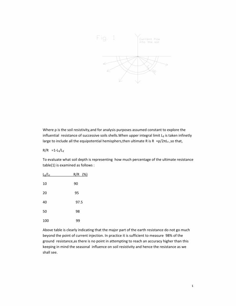
We should ,therefore,be much concerned about the resistance of earth itself to flow of current.To know the nature of this resistance consider an electrode as shown in fig.1. The paths of current flow can be represented by rays in all directions through the soil within hemispherical bowls in series as shown by semi‐circles.Consider a hemispherical bowl of radius L to bigin with and a shell of infinitesmal thickness of dL .
Then its resistance will be dR=ρdL /2πL²
So that R=∫�₁�²ρdL /2πL²=(ρ/2π)(1/L₁‐1/L₂)
٤
Where ρ is the soil resistivity,and for analysis purposes assumed constant to explore the influential resistance of successive soils shells.When upper integral limit L₂ is taken infinetly large to include all the equipotential hemisphers,then ultimate R is R�=ρ/2πL₁ ,so that,
R/R� =1‐L₁/L₂
To evaluate what soil depth is representing how much percentage of the ultimate resistance table(1) is examined as follows :
L₂/L₁ R/R� (%)
10 90
20 95
40 97.5
50 98
100 99
Above table is clearly indicating that the major part of the earth resistance do not go much beyond the point of current injection. In practice it is sufficient to measure 98% of the ground resistance,as there is no point in attempting to reach an accuracy higher than this keeping in mind the seasonal influence on soil resistivity and hence the resistance as we shall see.
٥
3b‐ Nature of soil :
The nature of soil has the greatest influence on the value of earth resistance .As it has been pointed out earlier ,the major part of any earth resistance lies not far away from the surface of of the soil.And unfotunately soil sec tions ,in general,at these points have their greatest resistivities.Therefore,it should be apparent that the role of grounding or earthing systems is to reduce whatever possible of these large resistance layer and convey the electrical connection to deeper and hence lower resistance as much as practicable.In general the the resistivity (and hence the resistance of a grounding system)deoend on the following facters:
1‐Type of the soil
2‐Salt concentration.
3‐Moisture content.
4‐ Temperature of the soil.
Soils differ in their resistivities,and only resistivity test can reveal to what extent a soil is resistive.Salt concentration reduce the resistivity of a soil,and the addition of salts to the soil immediately surrounding the ground electrode will play a role in reducing resistivity.Soils that have higher moisture content exhibit low resistivity.According to experiments carried out on red clay soil the resistivity increased 300 times when the moisture content decreased from 22% to 10%. Very dry soils as well as frozen ones also have large resitivities.
3c‐ Earth Resistance Measuring Instruments.
In the article of “ Test Procedures “ that will follow,direct‐reading instruments are made use of in measuring ground system resistance.These instruments have to be of the type that can disclude some sources of measuring error arising from circulating currents of power frequency or its harmonics.Therefore such test instruments are required to inject test currents of a frequency different from the power frequency and its harmonics.Such an injected current test frequency is to be according to the following formula :
F�=(2n+1)F�/2
Where, F�=frequency of the instruments injected test current.
F�=power frequency=50 Hz .
n=any integer number greater than zero .
If an instrument design is using n=6 , for instance, then its internal generator can inject a test current of frequency of 325 Hz,which is different from the power frequency and its harmonics.
The instrument is to be capable of selectively injecting and picking up its injected signal only.This separation capability is carried out using high selectivity filters,and a very adequate

٦
filtering configeration is the “synchronous rectifier “. The type of test instrument used better be able ,through self diagnostic feature, to warn the operator when there is an improper connection or if the injected current is bellow the required level so that such improper conditions would not pass unnoticed.The available ground resistsnce testers have typically accuracies of around +/‐ 2% .It is to be noted that in, ground resistance measurements ,errors of 5 to 10% are tolerated because such a resistsnce can vary with seasonal changes or temperature and these changes may be considerable, that is the reason why accuracies, higher than indicated above, are not called for.
3d‐ Test Procedures
The earth electrode can be thought of as being surrounded by shells of earth ,each of the same thickness .The shell closest to the electrode has the smallest surface area and offers the greatest resistance .The next shell has larger area and lower resistance ,and so on.A distance eventually will be reached where the additional earth shells do not add significantly to the resistance.Each electrode resistance is measured to remote earth,which is the earth outside the electrode influence.A larger electrode system requires greater distance before its influence decreases to a negligible level.
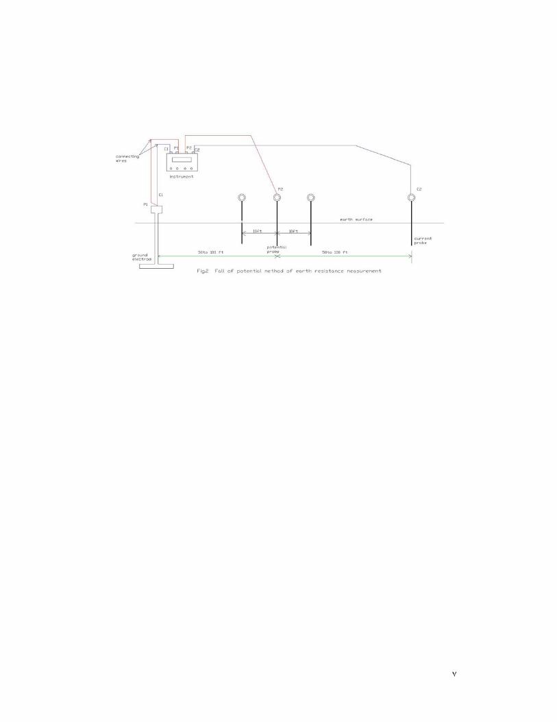
A typical test set has 4 terminals—2 current terminals marked C1 and C2, and 2 potential terminals marked P1and P2.
As shown in Fig.2 one current terminal (C1) is connected to the earh electrode under test and the other (C2) to a probe driven in the earh some distance away.The test set instrument injects a cuurent into the earth between the two current terminals.One potential terminal(P1) also is connected to the earth electrode but the other potential terminal(P2)is connected to a separate probe driven in the earth between the electrode and the current probe(C2).The potential probes detect the voltage due to the current injected in the earth by the current terminals .The test set measures both the current and voltage and internally calculates and then displays the resistance, as R=V/I . The resistance indicated by the test is the resistance between the earth electrode and the potential probe.If the current and potential probes both are far enough awayfrom the electrode,that is ,outside the influence of the electrode ,the reading corresponds to the resistance of the electrode to remote earth.
٧
٨
3e‐Fall of Potential
The ‘Fall of Potential ‘ is the most common method of measuring ground resistance,but it requires special procedurs when used to measure ‘Large Electrode Systems ‘ (that may include numerous types of bonded electrodes such as ground rods,grids,concrete encased electrodes ,water well casings,and buried radial wires).For ‘ Small Electrode Systems ‘ (such as one or few ground rods or a small loop ) the ‘Fall of Potential ‘requires only simple procedures.The basic procedure (refere to Fig. 2 )is to first connect the test set terminals C1 and P1 to the ground electrode under test,and C2 terminal to a current probe located some distance away from the electrode ,finally the test sets P2 terminal is connected to the potential probe located a variable distance between.The two probes are normally located in a straight line.At each potential probe location ,the resistance readout is recorded. The results of these measurements are then plotted to graphically determine the electrode resistance.
Fig. 3 is showing the resistance areas around the grounding system and the current probe.Basically the farther the distance between them the less the influence of the hemospherical resistance areas as they do not overlap as far as they are separated by enough distance.
Fig. 3 is also showing variation of resistance with distance.For the situation where the current probe is far enough from the tested ground system,the resistance value levels off having a flat zone .This flat zone is indicating absence or minimum effect of overlap of the influential shells of resistance.
Researches revieled that the value of the tested ground is within this flat zone and in particular at 61.8% of the distance from the tested electrode to the current probe,provided that the resistivity of the soil is homogenious .

٩
١٠
3f‐Fall of Potential for ‘Small Electrodes ‘
As mentioned earlier ,a ground system composed of one or a few ground electrodes or a small loop is considered as ‘small electrode system’ which can follow the procedure as bellow :
Terminals C1 and P1 are connected as shown in Fig, 2 .The current pole is driven into earth
(to a depth of 8 ‐12 inches ) at a distance of 100‐200 ft. from the ground electrode under test ,and the terminal C2 of the test instrument is connected to it.The potential probe is driven into the earth ,to the same depth as the current probe,midway between the tested rod and the current probe and connected to terminal P2 of the test instrument.The resistance value readout is recorded when the potential terminal is midway.The potential probe is then moved 10 ft. farther away from the tested electrode and the second resistance value readout is recorded.Finally,the potential probe is moved a distance of
10 ft. closer to the tested electrode and the third resistance value readout is recorded.
The average resistance of the three readouts are calculated and called R₀ .
The results are analyzed according to the following criteria :
IF (R₀‐R₁ )/R₀ and ( R₀‐R₂ )/R₀ and also (R₀‐R₃ )/R₀ are all as small as 2‐3% then R₀
can be taken as the resistance of the ground rod under test.
IF on the other hand above criteria do not yield the maximum limits of disagreement as
above ,then the procedure for ‘Large Electrode Systems ‘ ,that will follow, are carried out.
3g‐‘ Fall of Potential’ Large Electrode Systems.
A set of measurements can be made to save time but may not yield the required accuracy if the current and potential probes are not outside the electrical influence of the electrode system.by reference to Fig.2 :
First,the current probe is driven to earth 400 to 600 ft. from the tested electrode ,and the potential probe is driven to earth 61.8% of the distance from the electrode to the current probe.The resistance is measured under this condition .
Second, the potential probe is moved 50 to 100 ft.farther away from its presant position ,and the resistance again recorded.
١١
Third, the current probe is moved closer by 50 to 100 ft. and the potential electrode is placed at 61.8 % of the new distance, then the resistance is measured under this new set of distances.
Fourth, The above steps are repeated.
Fifth, The resistance readings are averaged.
As it was discussed earlier ,the ground electrode can be thought of as being surrounded by concentric shells of earth.The current probe is also surrounded by earth shells but with a relatively smaller influence.It is necessary to locate the current probe far enough away so that the influential shells do not overlap.
Fall of Potential method measurements are based on the distance of the current and potential probes from the center of the tested electrode.Most of the time ,the location of the center of the electrode is unknown,in particular when it consists of a lot of types of bonded electrodes like grids,rods,water well casings,and radial wires.For situations as these special procedures are followed like the Slope Method or the Intersecting Curves.
As it was stated earlier ,if space is not posing measurement restrictions, then the farther the current probe is placed the less is the error which arise from interfering earth resistance areas. Theoretical and experimental work indicate that the current probe has to be placed 10 to 20 times the ground maximum length or the ‘Maximum Electrode Dimension ‘ for larger ground systems.For instance if the system is constituted of rectaingular or square shape then the ‘Maximum Electrode Dimension’ is the diagonal length.
As the 61.8% measurement is based on homogenious soil resistivity to a depth around 10 times the ‘Maximum Electrode Dimension ‘ a condition that cannot be confirmed with certainity ,therefore some measures can be taken to endup with a satisfactory measurement result.
It is arranged to obtain three sets of measurements with the current probe distances of 200 ft. away from the tested electrode ,and the second set of measurement with a distance of 300ft. and finally a set with 400 ft.and ,whenever, possible in different directions.
For each set of measurement ,the potential probe is placed at 20 ft. away from the tested ground and a resistance readout is recorded.Then the potential probe is moved 5 ft. to 10 ft.farther away to record the second resistance readout .This is repeated at each potential probe location increament of 5 ft. to 10 ft. untill it reaches about 20 ft. from the current probe.
Finally three sets of measurements are obtained and plotted with distance from the ground electrode.These curves are examined to detect any reading that cause departure from smoothness of curve and the operator decides if a replacement measurement has to be done. From the resulting curves (an example of which is shown in Fig. 4 )the slopes in ohm/ ft are calculated at mid points and are analyzed according to the following :

١٢
Does the slope exhibit horizontality?
Is the slope small?
yesAverage the
resistance value @ ٦١.٨%
No
yes
Slope of curve
No
Carryout ‘SLOPE METHOD’ or the ‘INTERSECTING CURVES’
procedure
Fig. ٤

١٣
3h‐The procedure of ‘ Intersecting Curves ‘
In particular with large ground systems,whenever the center of such a system is not known accurately ,the data obtained by ‘Fall of Potential ‘ can further be cross‐checked using the Intersecting Curves procedure .In this procedure the actual center of the grounding system is assumed to be a distance X from the previous test connection. Assumed values of X are varied in inceaments of 10 ft.,to calculate the modified location of the potential probe which should equal to : 61.8%(X+D)‐X . With these distances ,and making interpolations as necessary, corresponding resistances are read from the original data.This process is repeated for all the sets of the data .This new sets of data are plotted with resistance as ordinate against the modified distance and called ‘Intersecting Curves ‘, as the intersecting point of the curves indicate actual ground resistance of the system.
With this procedure ,and if the curves do not intersect at one point but rather form a common small shape,then the size of such a shape has to be evaluated in order to either accept the results,or recheck and possibly repeat the test,because the size of such a shape is representing the uncertainity of the measurement.When the curves do not intersect at all,the whole test and instrument have to be checked thoroughly.
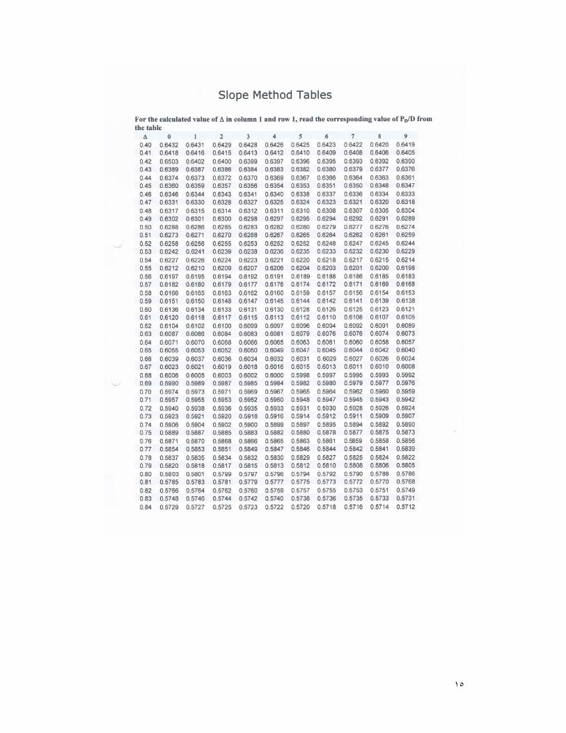
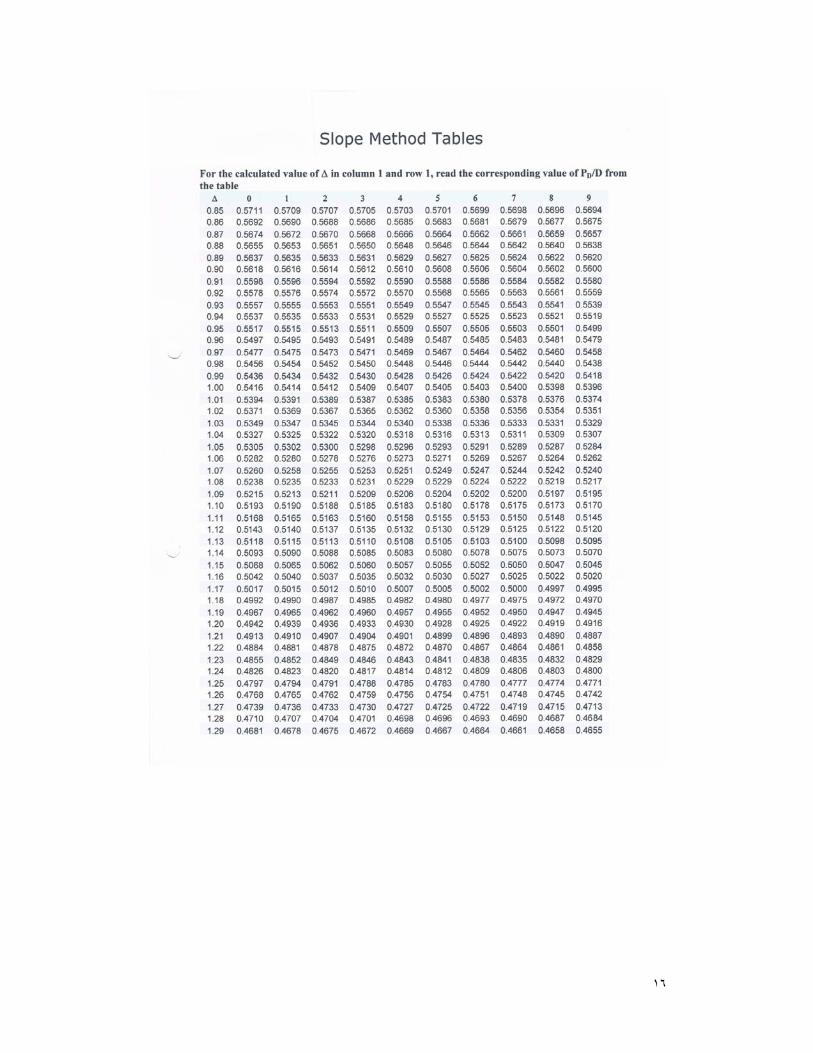
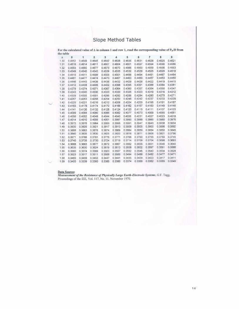
3i‐The ‘Slope Method ‘
This method can also be used to cross‐check the other methods or it can be used to measure the ground system resistance.
Distance from the ground rod are calculated as 0.2D ,0.4D,and 0.6D, where D is the separation between the current probe and the ground system.The resistances R1,R2,and R3 , in the same respective order, are read,with interpolation as necessary,from the data corresponding to above distances.The change of slope is calculated as follows :
Δ=(R3‐R2)/(R2‐R1)
The ‘Slope Method ‘table is entered with above change of slope to read the value of
Pd/D .This latter value is multiplied by D to find Pd . With this Pd distance the data is entered to find the value of the resistance.Similarly ,the same procedure is carried out for all the data sets.When the resistances are reasonably close the values can be used with confidence.
١٤
4‐REMARKS
‐The value of ground resistance is not strictly indicated by codes. Apparently codes indicate that a groud rod having 25 ohm resistance should be supplimented by another rod.Some installations require 5 ohm,others reqyire 3 ohms.Substations and power plants may require no more than 0.5 ohms.
‐The depth to which a ground electrode is driven is an important factor in lowering ground resistance,and it should be long enough to reach the permanent moisture level of the soil.For this purpose ,and instead using hand held hammer,an electric demolition hammer(a smaller version of a road breaker ) is made use of .Ground rods ae usually copper‐coated steel,the most common is 10 ft. in length and of ½ inches diameter.
‐Driving deep electrodes bonded with existing ground systems is recommended when the existing ystem is tested to be one of high resitance.
‐Multiple rods provide another effective means of improving ground systems,and the more are spaced, within practical limits,the better the ohmic status of the system will be .Vertically driven rods are generally used where bedrock is beyond a depth of about 10 ft.On the other hand ,where bedrock is near the surface ,electrodes are unpractical to use.In such cases solid wires ,stranded cables,or horizotal strips are used.Also ,high resistivity rock can be overlain by clay that have low resistivity.
‐Ion‐producing chemicals added to the soil immediately surrounding electrodes help in lowering resistance.The chemicals may gradually washed away by rainfall and natural drainage.Inaddition ,there are some reservations in resorting to chemicals arising from concerns of invirenmental protection.
5‐REFERANCES
1‐Earth resistance measurement‐Duncan Instruments Canada
2‐Safe Permanent Grounding‐ George Hamburger‐Copperweld steel co.
3‐Getting down to earth‐Megger inst.co.
4‐Principles and practice of earth electrode measurements‐William D. Reeve
5‐Slope Method—Jeff Jowett
١٥
١٦
١٧