electrical grid requirements dowec · electrical grid requirements dowec dowec nr: 10042 rev. 3 ......
TRANSCRIPT

Electrical grid requirements Dowec
DOWEC Nr: 10042Rev. 3
Name: Signature: Date:Written by: JBZ 15-04-04Checked by FG, JAK,CSPSigned by: OSO
Version date No ofpages
0 all New / review document1 13/05/02 div Update to Dutch grid-codes from version April2 10/10/02 all Update to UK recommendation G75/13 22/10/03 all Public version
TITLE DOCUMENT: ELECTRICAL GRID REQUIREMENTS DOWEC VERSION: 3DOCUMENT NO.: 10042 PAGE: 2/22
10042_003.DOC REV. 0 SIDE 2 OF 22 15-04-04
1 . CONTENTS
1. CONTENTS..............................................................................................................................................2
2. SCOPE.......................................................................................................................................................3
3. DEFINITIONS..........................................................................................................................................4
4. GENERAL NORMATIVE REFERENCE LIST ..................................................................................54.1. TURBINE SPECIFIC NORMATIVE REFERENCE LIST ..........................................................................................5
5. PARK SIZE RELATED REQUIREMENTS.........................................................................................6
6. REQUIREMENTS FOR THE WIND FARM AT THE ONSHORE CONNECTION POINT ........76.1. POWER PLANNING AND CONTROL REQUIREMENTS......................................................................................76.2. REACTIVE POWER REQUIREMENTS................................................................................................................96.3. VOLTAGE / CURRENT RELATED REQUIREMENTS......................................................................................106.4. FREQUENCY/VOLTAGE REQUIREMENTS ............................................................................................................126.5. MEASUREMENT BY DTE OR UTILITY (TIME SYNCHRONISED)...........................................................................146.6. PARK MEASUREMENT & REGISTRATION ..........................................................................................................14
7. RELIABILITY .......................................................................................................................................157.1. RELIABILITY SHORE CONNECTION...................................................................................................................157.2. RELIABILITY WIND FARM COLLECTION PLATFORMS.........................................................................................157.3. RELAIBILITY WIND FARM GRID INFRASTRUCTURE ............................................................................................15
8. APPENDICES ........................................................................................................................................168.1. APPENDIX 1: VOLTAGE FREQUENCY PICTURE ...............................................................................................178.2. APPENDIX 2: FAILURE EFFECT ANALYSE.......................................................................................................198.3. APPENDIX 3: HV GRID IN THE NETERLANDS.....................................................................................................218.4. APPENDIX 4: MEETINGS AND DOCUMENTATION LIST....................................................................................228.5. APPENDIX 5: RESPONSIBLE ENGINEERS ...........................................................................................................22

TITLE DOCUMENT: ELECTRICAL GRID REQUIREMENTS DOWEC VERSION: 3DOCUMENT NO.: 10042 PAGE: 3/22
10042_003.DOC REV. 0 SIDE 3 OF 22 15-04-04
2 . SCOPE
This document gives an overview of the technical requirements for the electrical connection of largeoffshore wind farms. The focus in this overview is on wind farms 20-100 km from the shore and parksizes of 100 MW and more. This document is not intended as a replacement of the national regulations,but as a summary of all requirements in The Netherlands, Denmark, Germany and UK. Information onthe requirements in other countries may be added later. Local deviations can be expected, since nationalregulations for large offshore plants are still in development. Furthermore, local grid operators arealways entitled to specify additional requirements. Experience from the first large offshore farms mayalso lead to additional requirements or changes.
Wind farms are not an ideal power source since the wind is stochastic in nature. This variability will haveconsequences for the ability to fulfil the current grid requirements, written for large power plantsequipped with synchronous generators. Wind farms can not meet all requirements, but on some aspectswind power plants may perform much better than conventional power plants (for instance fast powercontrol).
If several documents on the same requirement are available, the worst-case scenario was taken in thischecklist. If behind an item both NL and DK are mentioned, then both countries have this requirement. Aspreadsheet was prepared which includes the regulations for NL, DK, D, UK.
Requirements are sorted on the basis of voltage, power, current etc. as opposed to sorting by normal versusexceptional conditions. Normal Operation Requirements are highlighted light grey.
This overview is prepared as part of the Dowec project. In the Dowec project a wind farm case studywill be made of:• a 100 MW farm, 20 km out of the coast;• a 600 MW farm, 60 km out of the coast;
Which corresponds to two major Dutch projects (see Dowec Terms of Reference).
The document is considered to be a living document and new information will be added when appropriate.
TITLE DOCUMENT: ELECTRICAL GRID REQUIREMENTS DOWEC VERSION: 3DOCUMENT NO.: 10042 PAGE: 4/22
10042_003.DOC REV. 0 SIDE 4 OF 22 15-04-04
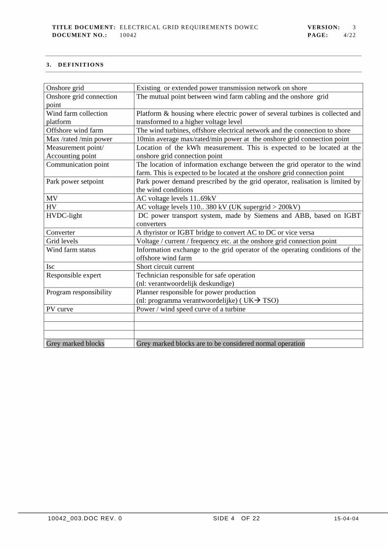
3 . DEFINITIONS
Onshore grid Existing or extended power transmission network on shoreOnshore grid connectionpoint
The mutual point between wind farm cabling and the onshore grid
Wind farm collectionplatform
Platform & housing where electric power of several turbines is collected andtransformed to a higher voltage level
Offshore wind farm The wind turbines, offshore electrical network and the connection to shoreMax /rated /min power 10min average max/rated/min power at the onshore grid connection pointMeasurement point/Accounting point
Location of the kWh measurement. This is expected to be located at theonshore grid connection point
Communication point The location of information exchange between the grid operator to the windfarm. This is expected to be located at the onshore grid connection point
Park power setpoint Park power demand prescribed by the grid operator, realisation is limited bythe wind conditions
MV AC voltage levels 11..69kVHV AC voltage levels 110.. 380 kV (UK supergrid > 200kV)HVDC-light DC power transport system, made by Siemens and ABB, based on IGBT
convertersConverter A thyristor or IGBT bridge to convert AC to DC or vice versaGrid levels Voltage / current / frequency etc. at the onshore grid connection pointWind farm status Information exchange to the grid operator of the operating conditions of the
offshore wind farmIsc Short circuit currentResponsible expert Technician responsible for safe operation
(nl: verantwoordelijk deskundige)Program responsibility Planner responsible for power production
(nl: programma verantwoordelijke) ( UK TSO)PV curve Power / wind speed curve of a turbine
Grey marked blocks Grey marked blocks are to be considered normal operation
TITLE DOCUMENT: ELECTRICAL GRID REQUIREMENTS DOWEC VERSION: 3DOCUMENT NO.: 10042 PAGE: 5/22
10042_003.DOC REV. 0 SIDE 5 OF 22 15-04-04
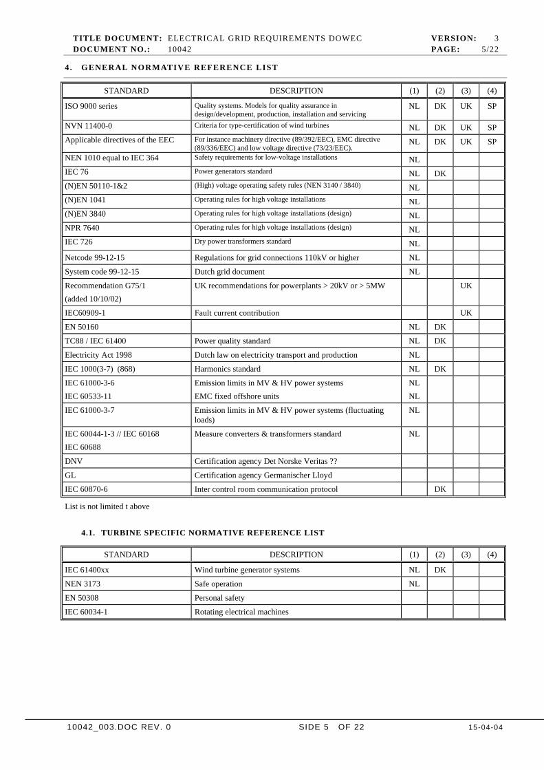
4 . GENERAL NORMATIVE REFERENCE LIST
STANDARD DESCRIPTION (1) (2) (3) (4)
ISO 9000 series Quality systems. Models for quality assurance indesign/development, production, installation and servicing
NL DK UK SP
NVN 11400-0 Criteria for type-certification of wind turbines NL DK UK SPApplicable directives of the EEC For instance machinery directive (89/392/EEC), EMC directive
(89/336/EEC) and low voltage directive (73/23/EEC).NL DK UK SP
NEN 1010 equal to IEC 364 Safety requirements for low-voltage installations NLIEC 76 Power generators standard NL DK(N)EN 50110-1&2 (High) voltage operating safety rules (NEN 3140 / 3840) NL(N)EN 1041 Operating rules for high voltage installations NL(N)EN 3840 Operating rules for high voltage installations (design) NLNPR 7640 Operating rules for high voltage installations (design) NLIEC 726 Dry power transformers standard NL
Netcode 99-12-15 Regulations for grid connections 110kV or higher NL
System code 99-12-15 Dutch grid document NL
Recommendation G75/1(added 10/10/02)
UK recommendations for powerplants > 20kV or > 5MW UK
IEC60909-1 Fault current contribution UK
EN 50160 NL DK
TC88 / IEC 61400 Power quality standard NL DK
Electricity Act 1998 Dutch law on electricity transport and production NL
IEC 1000(3-7) (868) Harmonics standard NL DK
IEC 61000-3-6IEC 60533-11
Emission limits in MV & HV power systemsEMC fixed offshore units
NLNL
IEC 61000-3-7 Emission limits in MV & HV power systems (fluctuatingloads)
NL
IEC 60044-1-3 // IEC 60168IEC 60688
Measure converters & transformers standard NL
DNV Certification agency Det Norske Veritas ??
GL Certification agency Germanischer Lloyd
IEC 60870-6 Inter control room communication protocol DK
List is not limited t above
4.1. TURBINE SPECIFIC NORMATIVE REFERENCE LIST
STANDARD DESCRIPTION (1) (2) (3) (4)
IEC 61400xx Wind turbine generator systems NL DK
NEN 3173 Safe operation NL
EN 50308 Personal safety
IEC 60034-1 Rotating electrical machines
TITLE DOCUMENT: ELECTRICAL GRID REQUIREMENTS DOWEC VERSION: 3DOCUMENT NO.: 10042 PAGE: 6/22
10042_003.DOC REV. 0 SIDE 6 OF 22 15-04-04
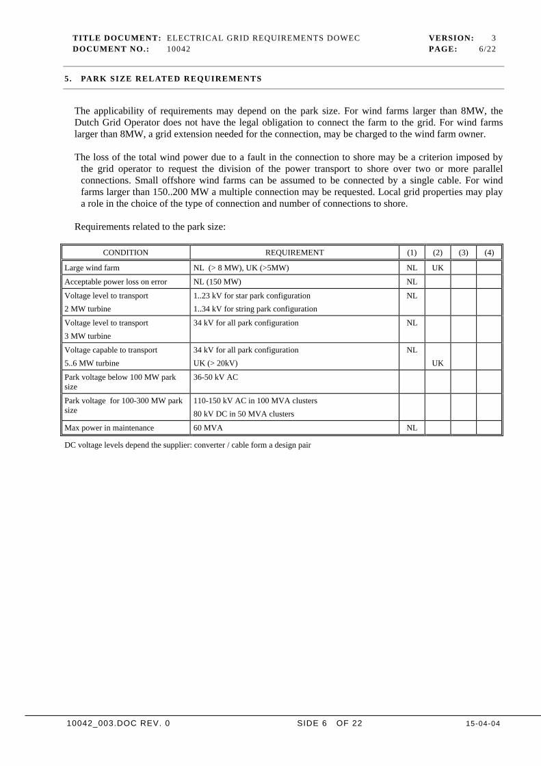
5 . PARK SIZE RELATED REQUIREMENTS
The applicability of requirements may depend on the park size. For wind farms larger than 8MW, theDutch Grid Operator does not have the legal obligation to connect the farm to the grid. For wind farmslarger than 8MW, a grid extension needed for the connection, may be charged to the wind farm owner.
The loss of the total wind power due to a fault in the connection to shore may be a criterion imposed bythe grid operator to request the division of the power transport to shore over two or more parallelconnections. Small offshore wind farms can be assumed to be connected by a single cable. For windfarms larger than 150..200 MW a multiple connection may be requested. Local grid properties may playa role in the choice of the type of connection and number of connections to shore.
Requirements related to the park size:
CONDITION REQUIREMENT (1) (2) (3) (4)
Large wind farm NL (> 8 MW), UK (>5MW) NL UK
Acceptable power loss on error NL (150 MW) NL
Voltage level to transport2 MW turbine
1..23 kV for star park configuration1..34 kV for string park configuration
NL
Voltage level to transport3 MW turbine
34 kV for all park configuration NL
Voltage capable to transport5..6 MW turbine
34 kV for all park configurationUK (> 20kV)
NLUK
Park voltage below 100 MW parksize
36-50 kV AC
Park voltage for 100-300 MW parksize
110-150 kV AC in 100 MVA clusters80 kV DC in 50 MVA clusters
Max power in maintenance 60 MVA NL
DC voltage levels depend the supplier: converter / cable form a design pair
TITLE DOCUMENT: ELECTRICAL GRID REQUIREMENTS DOWEC VERSION: 3DOCUMENT NO.: 10042 PAGE: 7/22
10042_003.DOC REV. 0 SIDE 7 OF 22 15-04-04
6 . REQUIREMENTS FOR THE WIND FARM AT THE ONSHORE CONNECTION POINT
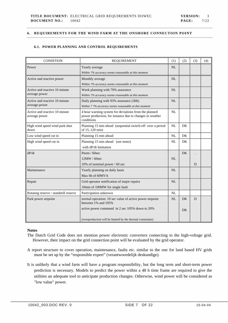
6.1. POWER PLANNING AND CONTROL REQUIREMENTS
CONDITION REQUIREMENT (1) (2) (3) (4)
Power Yearly averageWithin ?% accuracy seems reasonable at this moment
NL
Active and reactive power Monthly averageWithin ?% accuracy seems reasonable at this moment
NL
Active and reactive 10 minuteaverage power
Week planning with 70% assuranceWithin ?% accuracy seems reasonable at this moment
NL
Active and reactive 10 minuteaverage power
Daily planning with 93% assurance (36h)Within 7 ?% accuracy seems reasonable at this moment
NL
Active and reactive 10 minuteaverage power
4 hour warning system for deviations from the plannedpower production, for instance due to changes in weatherconditions
NL
High wind speed wind park shutdown
Planning 15 min ahead (sequential switch-off over a periodof 15..120 min)
NL DK
Low wind speed cut in Planning 15 min ahead NL DK
High wind speed cut in Planning 15 min ahead (see notes) with dP/dt limitation
NL DK
dP/dt Pnom / 60sec12MW / 60sec10% of nominal power / 60 sec
NLDK .
D
Maintenance Yearly planning on daily basisMax 6h of 60MVA
NL
Repair Grid operator notification of major repairs10min of 100MW for single fault
NL
Rotating reserve / standstill reserve Participation unknown NL
Park power setpoint normal operation: 10 sec value of active power setpointbetween 1% and 105%active power command in 2 sec 105% down to 20%
(overproduction will be limited by the thermal constraints)
NL DK
DK
D
NotesThe Dutch Grid Code does not mention power electronic converters connecting to the high-voltage grid.
However, their impact on the grid connection point will be evaluated by the grid operator.
A report structure to cover operation, maintenance, faults etc. similar to the one for land based HV gridsmust be set up by the “responsible expert” (verantwoordelijk deskundige).
It is unlikely that a wind farm will have a program responsibility, but the long term and short-term powerprediction is necessary. Models to predict the power within a 48 h time frame are required to give theutilities an adequate tool to anticipate production changes. Otherwise, wind power will be considered as"low value" power.
TITLE DOCUMENT: ELECTRICAL GRID REQUIREMENTS DOWEC VERSION: 3DOCUMENT NO.: 10042 PAGE: 8/22
10042_003.DOC REV. 0 SIDE 8 OF 22 15-04-04
Soft switch in /out procedures are necessary to give grid control equipment, for example transformer voltagecontrol or power control of large generators, time to adjust to new conditions.
Power regulation speed of 150-200 MW power plants is expected to be around 12 MW/min. Assuming anequal amount of rotating reserve, this means 36 MW/min for a wind farm of 600 MW and a shut downfrom maximum power to zero should take 15 min. This value appears to be acceptable for all involvedparties.

TITLE DOCUMENT: ELECTRICAL GRID REQUIREMENTS DOWEC VERSION: 3DOCUMENT NO.: 10042 PAGE: 9/22
10042_003.DOC REV. 0 SIDE 9 OF 22 15-04-04
6.2. REACTIVE POWER REQUIREMENTS
CONDITION REQUIREMENT (1) (2) (3) (4)
Power factor during normaloperation
Between 1 and 0.8 inductive (nl >50kV) (UK 0.85) 1..and0.85 cap (nl > 50kV) (UK 0.95)The power factor affects the voltage regulation and is subjectto discussion with the utilities (Utility preference +0.9 to –0.9)
Reactive power, also in no-wind periods, is valuable
NLNL
DK UKUK
Reactive power setting Reactive power command every 10 sec NL DK
NOTE
If capacitieve reactive power is needed, the logical place to produce this, would be at the onshore gridconnection point. In case the wind farm is not fully loaded or if the cable has spare capacity, thenreactive power production at the farm is an option.
TITLE DOCUMENT: ELECTRICAL GRID REQUIREMENTS DOWEC VERSION: 3DOCUMENT NO.: 10042 PAGE: 10/22
10042_003.DOC REV. 0 SIDE 10 OF 22 15-04-04
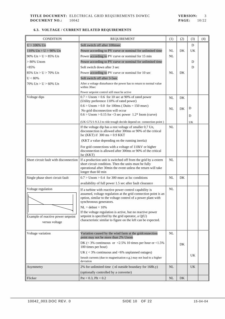
6.3. VOLTAGE / CURRENT RELATED REQUIREMENTS
CONDITION REQUIREMENT (1) (2) (3) (4)
U > 106% Un110% Un > U > 90% Un90% Un > U > 85% Un> 80% Unom<85%85% Un > U > 70% UnU < 80%70% Un > U > 60% Un
Soft switch off after 100msecPower according to PV curve or nominal for unlimited timePower according to PV curve or nominal for 15 minPower according to PV curve or nominal for unlimited timeSoft switch down after 3 secPower according to PV curve or nominal for 10 secSoft switch off after 3-5secAfter a voltage disturbance the power has to return to normal valuewithin 30sec
Power setpoint control still must be active
NLNL
NL
DK
DK
DUK
DD
Voltage dips 0.7 > Unom > 0.6 for 10 sec at 90% of rated power(Utility preference 110% of rated power)0.6 > Unom > 0.0 for 100ms ( Duits = 150 msec) No grid disconnection will occur0.6 > Unom > 0.15 for <3 sec power 1.2* Inom (curve)
(UK G75/1-9.3.3 to ride trough decide depend on connection point )
NL
NL
DK
DK D
D
UKIf the voltage dip has a rest voltage of smaller 0,7 Un,disconnection is allowed after 300ms or 90% of the criticalIsc (KKT) if 300 ms > 0.9 KKT (KKT a value depending on the running inertia)
For grid connections with a voltage of 110kV or higherdisconnection is allowed after 300ms or 90% of the criticalIsc (KKT)
NL
Short circuit fault with disconnection If a production unit is switched off from the grid by a externshort circuit condition. Then the units must be fullyoperational after 30min the event unless the return will takelonger than 60 min
NL
Single phase short circuit fault 0.7 > Unom > 0.4 for 300 msec at Isc conditionsavailability of full power 1.5 sec after fault clearance
NL DK
Voltage regulation
Example of reactive power setpoint versus voltage
If a turbine with reactive power control capability isassumed, voltage regulation at the grid connection point is anoption, similar to the voltage control of a power plant withsynchronous generators.NL = debiet = 10%If the voltage regulation is active, but no reactive powersetpoint is specified by the grid operator, a Q(U)characteristic similar to figure on the left can be expected.
NL
Voltage variation Variation caused by the wind farm at the gridconnectionpoint may not be more than 2% UnomDK (< 3% continuous or <2.5% 10 times per hour or <1.5%100 times per hour)UK ( < 3% continuous and <6% unplanned outages)Inrush currents (due to magnetisation e.g.) may not lead to a higherdeviation
NL
DK
UK
Asymmetry 2% for unlimited time ( nl outside boundary for 168h.y)(optionally controlled by a converter)
NL UK
Flicker Pst < 0.3, Plt < 0.2 NL DK
TITLE DOCUMENT: ELECTRICAL GRID REQUIREMENTS DOWEC VERSION: 3DOCUMENT NO.: 10042 PAGE: 11/22
10042_003.DOC REV. 0 SIDE 11 OF 22 15-04-04
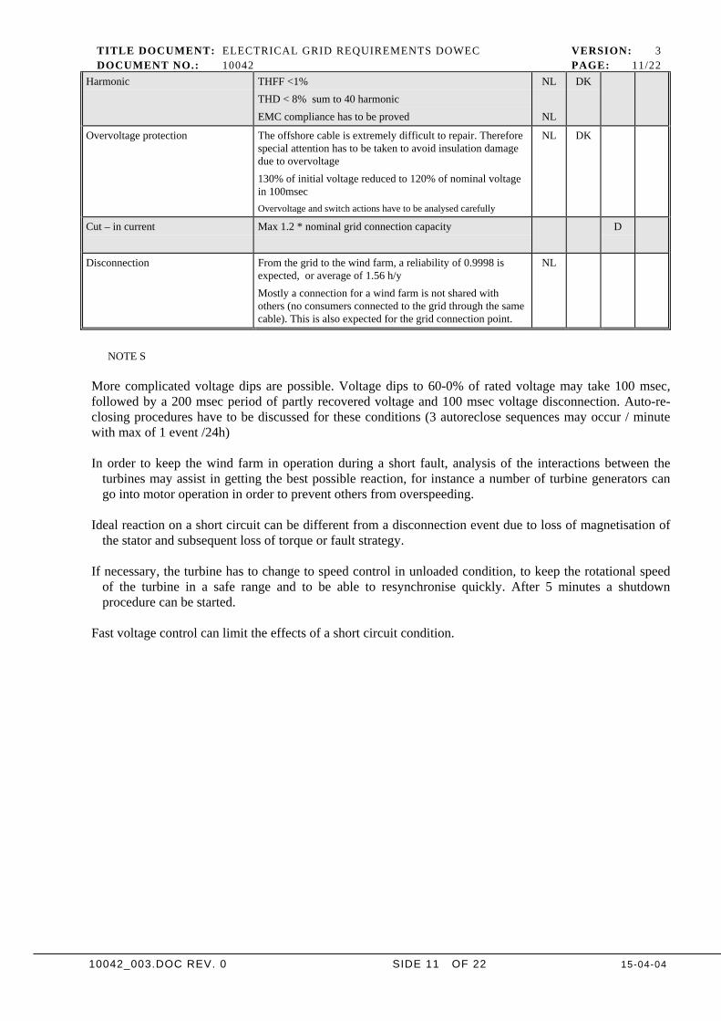
Harmonic THFF <1%THD < 8% sum to 40 harmonicEMC compliance has to be proved
NL
NL
DK
Overvoltage protection The offshore cable is extremely difficult to repair. Thereforespecial attention has to be taken to avoid insulation damagedue to overvoltage130% of initial voltage reduced to 120% of nominal voltagein 100msecOvervoltage and switch actions have to be analysed carefully
NL DK
Cut – in current Max 1.2 * nominal grid connection capacity D
Disconnection From the grid to the wind farm, a reliability of 0.9998 isexpected, or average of 1.56 h/yMostly a connection for a wind farm is not shared withothers (no consumers connected to the grid through the samecable). This is also expected for the grid connection point.
NL
NOTE S
More complicated voltage dips are possible. Voltage dips to 60-0% of rated voltage may take 100 msec,followed by a 200 msec period of partly recovered voltage and 100 msec voltage disconnection. Auto-re-closing procedures have to be discussed for these conditions (3 autoreclose sequences may occur / minutewith max of 1 event /24h)
In order to keep the wind farm in operation during a short fault, analysis of the interactions between theturbines may assist in getting the best possible reaction, for instance a number of turbine generators cango into motor operation in order to prevent others from overspeeding.
Ideal reaction on a short circuit can be different from a disconnection event due to loss of magnetisation ofthe stator and subsequent loss of torque or fault strategy.
If necessary, the turbine has to change to speed control in unloaded condition, to keep the rotational speedof the turbine in a safe range and to be able to resynchronise quickly. After 5 minutes a shutdownprocedure can be started.
Fast voltage control can limit the effects of a short circuit condition.
TITLE DOCUMENT: ELECTRICAL GRID REQUIREMENTS DOWEC VERSION: 3DOCUMENT NO.: 10042 PAGE: 12/22
10042_003.DOC REV. 0 SIDE 12 OF 22 15-04-04
6.4. FREQUENCY/VOLTAGE REQUIREMENTS
CONDITION REQUIREMENT (1) (2) (3) (4)
Frequency.
Time and power limited
Continuous operation between 48 and 51Hz (Norm = 50±0.1 Hz)Limited operation range between 45 and 48Hz (>5min)Limited operation range between 51 and 53Hz (>5min)if under/above these limits, disconnection after 0.3 sec isallowedContinuous operation between 47.5 and 51.5HzLimited operation range between <47.5Hz after 200sec)Limited operation range between >51.5Hz after 200sec)if under/above these limits, disconnection after 0.1 sec isallowedContinuous operation between 47.5 and 52HzLimited operation range between <47.5Hz after 20sec)
NL DK
D
UK
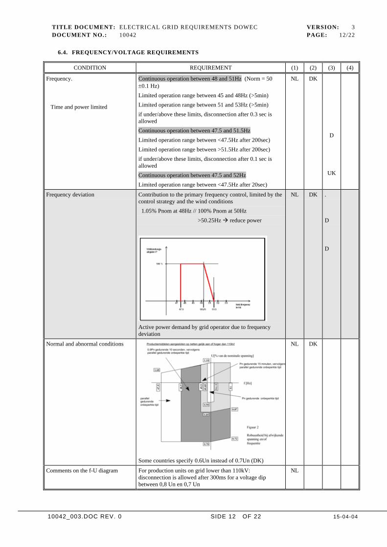
Frequency deviation Contribution to the primary frequency control, limited by thecontrol strategy and the wind conditions 1.05% Pnom at 48Hz // 100% Pnom at 50Hz >50.25Hz reduce power
Active power demand by grid operator due to frequencydeviation
NL DK .
D
D
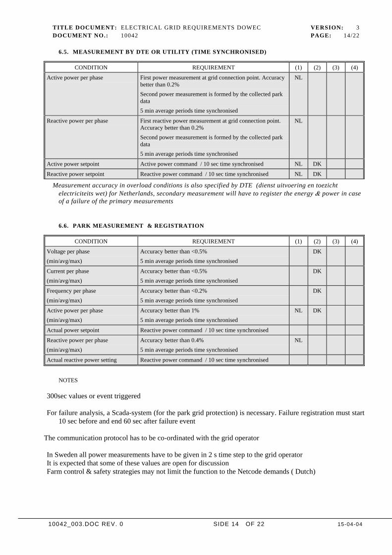
Normal and abnormal conditions
Some countries specify 0.6Un instead of 0.7Un (DK)
NL DK
Comments on the f-U diagram For production units on grid lower than 110kV:disconnection is allowed after 300ms for a voltage dipbetween 0,8 Un en 0,7 Un
NL

TITLE DOCUMENT: ELECTRICAL GRID REQUIREMENTS DOWEC VERSION: 3DOCUMENT NO.: 10042 PAGE: 13/22
10042_003.DOC REV. 0 SIDE 13 OF 22 15-04-04
NOTE S
Different frequencies do not cause a problem for wind turbines as long as the control strategy is adapted. Theonly limitation expected may be thermal overload and must be avoided by reducing the load.
Limitations for different voltage levels can be expected: thermal overload and exceeding the pull out-torquemust be avoided by reduction of the aerodynamic power.
Primary frequency control: the drop dP/df can be different for negative and positive frequency deviations.
TITLE DOCUMENT: ELECTRICAL GRID REQUIREMENTS DOWEC VERSION: 3DOCUMENT NO.: 10042 PAGE: 14/22
10042_003.DOC REV. 0 SIDE 14 OF 22 15-04-04
6.5. MEASUREMENT BY DTE OR UTILITY (TIME SYNCHRONISED)
CONDITION REQUIREMENT (1) (2) (3) (4)
Active power per phase First power measurement at grid connection point. Accuracybetter than 0.2%Second power measurement is formed by the collected parkdata5 min average periods time synchronised
NL
Reactive power per phase First reactive power measurement at grid connection point.Accuracy better than 0.2%Second power measurement is formed by the collected parkdata5 min average periods time synchronised
NL
Active power setpoint Active power command / 10 sec time synchronised NL DK
Reactive power setpoint Reactive power command / 10 sec time synchronised NL DK
Measurement accuracy in overload conditions is also specified by DTE (dienst uitvoering en toezichtelectriciteits wet) for Netherlands, secondary measurement will have to register the energy & power in caseof a failure of the primary measurements
6.6. PARK MEASUREMENT & REGISTRATION
CONDITION REQUIREMENT (1) (2) (3) (4)
Voltage per phase(min/avg/max)
Accuracy better than <0.5%5 min average periods time synchronised
DK
Current per phase(min/avg/max)
Accuracy better than <0.5%5 min average periods time synchronised
DK
Frequency per phase(min/avg/max)
Accuracy better than <0.2%5 min average periods time synchronised
DK
Active power per phase(min/avg/max)
Accuracy better than 1%5 min average periods time synchronised
NL DK
Actual power setpoint Reactive power command / 10 sec time synchronised
Reactive power per phase(min/avg/max)
Accuracy better than 0.4%5 min average periods time synchronised
NL
Actual reactive power setting Reactive power command / 10 sec time synchronised
NOTES
300sec values or event triggered
For failure analysis, a Scada-system (for the park grid protection) is necessary. Failure registration must start10 sec before and end 60 sec after failure event
The communication protocol has to be co-ordinated with the grid operator
In Sweden all power measurements have to be given in 2 s time step to the grid operatorIt is expected that some of these values are open for discussionFarm control & safety strategies may not limit the function to the Netcode demands ( Dutch)
TITLE DOCUMENT: ELECTRICAL GRID REQUIREMENTS DOWEC VERSION: 3DOCUMENT NO.: 10042 PAGE: 15/22
10042_003.DOC REV. 0 SIDE 15 OF 22 15-04-04
7 . RELIABILITY
7.1. RELIABILITY SHORE CONNECTION
The shore connection is a very critical point. If a major failure will happen the total power will drop tozero. Dividing the larger parks in to groups and redundant systems may be advisable.
CONDITION REQUIREMENT (1) (2) (3) (4)
Availability of grid connectionswitch boards
better than 99.78%0.16 failures per year for a system with 4 connectionsrepair time of 5 days
DK
Availability of cable connection(150kVA, 60km )
4 parallel connections of 60km better than 99.7%0.06 failures per year for a system with 4 connectionsrepair time of 21 daysmost probable failure cause are anchors
DK
7.2. RELIABILITY WIND FARM COLLECTION PLATFORMS
CONDITION REQUIREMENT (1) (2) (3) (4)
Availability of platform switchboards (150kV)
better than 99.78%0.16 with repair time of 5 days over 4 connections
DK
Platform transformer(150kV to 22(32) kV)
better than 99.4%4e-6 with repair time of 60 days over 4 connections
Availability of grid park switchboards(22 (32) kV)
better than 99.99%1.9e-7 with repair time of 30 days over 4 connectionsand at lease 8 outgoing fields
DK
7.3. RELAIBILITY WIND FARM GRID INFRASTRUCTURE
CONDITION REQUIREMENT (1) (2) (3) (4)
Park cable (60km) design to single fault <100MW for 10min max
better than 99.7%0.06 with repair time of 21 days over 4 * 8 connections
NL
Availability of turbine switchboards (22 (32) kV)
better than 99.99%1.9e-7 with repair time of 30 days over 4 connections
DK
(See grid reliability & cost report for more detail)
TITLE DOCUMENT: ELECTRICAL GRID REQUIREMENTS DOWEC VERSION: 3DOCUMENT NO.: 10042 PAGE: 16/22
10042_003.DOC REV. 0 SIDE 16 OF 22 15-04-04
8 . APPENDICES
TITLE DOCUMENT: ELECTRICAL GRID REQUIREMENTS DOWEC VERSION: 3DOCUMENT NO.: 10042 PAGE: 17/22
10042_003.DOC REV. 0 SIDE 17 OF 22 15-04-04
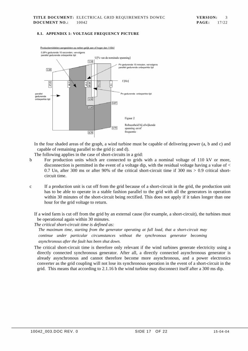
8.1. APPENDIX 1: VOLTAGE FREQUENCY PICTURE
In the four shaded areas of the graph, a wind turbine must be capable of delivering power (a, b and c) andcapable of remaining parallel to the grid (c and d).
The following applies in the case of short-circuits in a grid:b For production units which are connected to grids with a nominal voltage of 110 kV or more,
disconnection is permitted in the event of a voltage dip, with the residual voltage having a value of <0.7 Un, after 300 ms or after 90% of the critical short-circuit time if 300 ms > 0.9 critical short-circuit time.
c If a production unit is cut off from the grid because of a short-circuit in the grid, the production unithas to be able to operate in a stable fashion parallel to the grid with all the generators in operationwithin 30 minutes of the short-circuit being rectified. This does not apply if it takes longer than onehour for the grid voltage to return.
If a wind farm is cut off from the grid by an external cause (for example, a short-circuit), the turbines mustbe operational again within 30 minutes.
The critical short-circuit time is defined as:The maximum time, starting from the generator operating at full load, that a short-circuit maycontinue under particular circumstances without the synchronous generator becomingasynchronous after the fault has been shut down.
The critical short-circuit time is therefore only relevant if the wind turbines generate electricity using adirectly connected synchronous generator. After all, a directly connected asynchronous generator isalready asynchronous and cannot therefore become more asynchronous, and a power electronicsconverter as the grid coupling will not lose its synchronous operation in the event of a short-circuit in thegrid. This means that according to 2.1.16 b the wind turbine may disconnect itself after a 300 ms dip.
TITLE DOCUMENT: ELECTRICAL GRID REQUIREMENTS DOWEC VERSION: 3DOCUMENT NO.: 10042 PAGE: 18/22
10042_003.DOC REV. 0 SIDE 18 OF 22 15-04-04
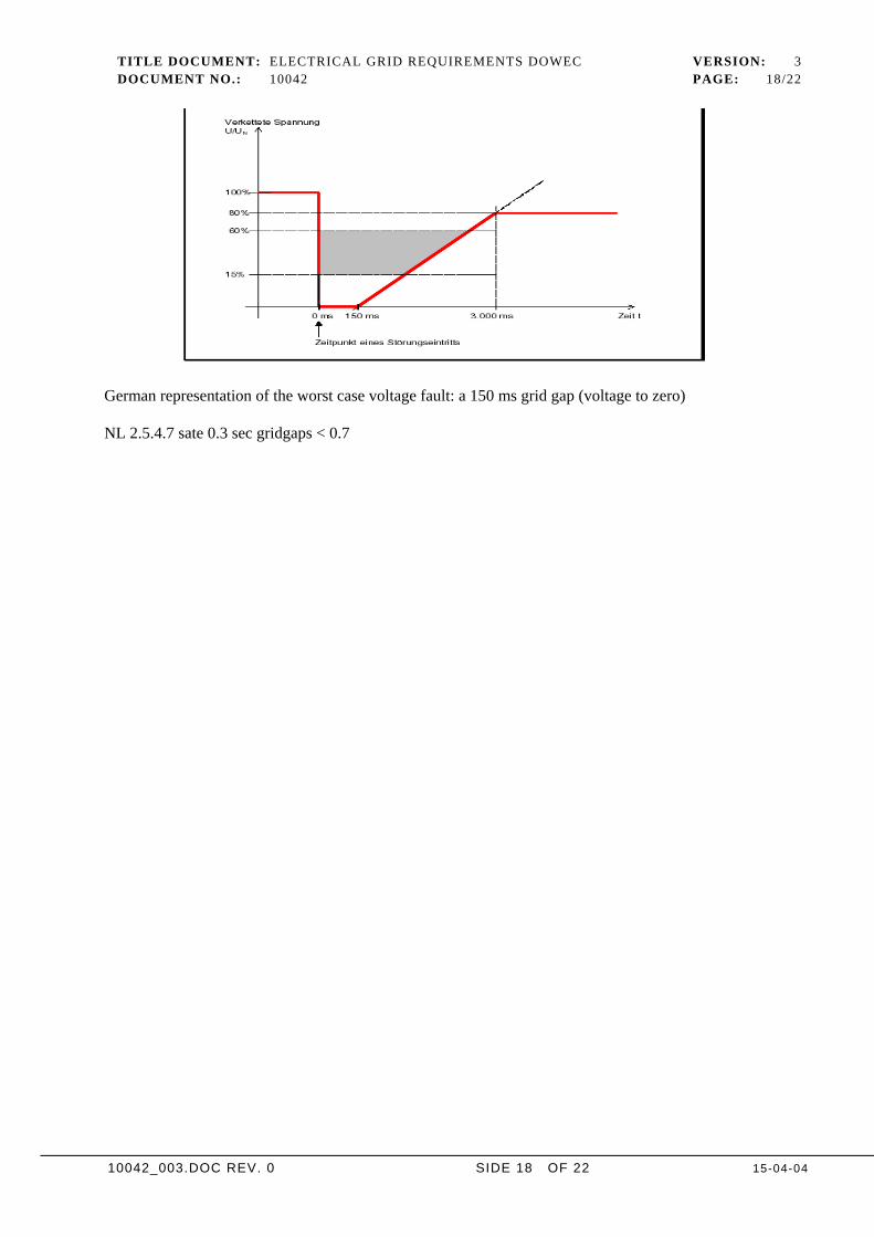
German representation of the worst case voltage fault: a 150 ms grid gap (voltage to zero)
NL 2.5.4.7 sate 0.3 sec gridgaps < 0.7
TITLE DOCUMENT: ELECTRICAL GRID REQUIREMENTS DOWEC VERSION: 3DOCUMENT NO.: 10042 PAGE: 19/22
10042_003.DOC REV. 0 SIDE 19 OF 22 15-04-04
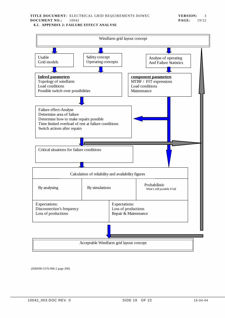
8.2. APPENDIX 2: FAILURE EFFECT ANALYSE
(ISBN90-5576-096-2 page 200)
Windfarm grid layout concept
UsableGrid models
Safety conceptOperating concepts
Analyse of operatingAnd Failure Statistics
Infeed parametersTopology of windfarmLoad conditionsPossible switch over possibilities
component parametersMTBF / FIT expressionsLoad conditionsMaintenance
Failure effect-AnalyseDetermine area of failureDetermine how to make repairs possibleTime limited overload of rest at failure conditionsSwitch actions after repairs
Critical situations for failure conditions
By analysing By simulationsProbabilistic
What’s still possible if fail
Expectations:Disconnection’s frequencyLoss of productions
Expectations:Loss of productionsRepair & Maintenance
Calculation of reliability and availability figures
Acceptable Windfarm grid layout concept
TITLE DOCUMENT: ELECTRICAL GRID REQUIREMENTS DOWEC VERSION: 3DOCUMENT NO.: 10042 PAGE: 20/22
10042_003.DOC REV. 0 SIDE 20 OF 22 15-04-04
Overall goalTo meet the total prize performance the overall goal for the park availability is set to 0.97That means that the goal for the turbine is 0.98 and the goal for the grid 0.99
Life cycle cost management methods for offshore wind turbine installations are given in [NRG,1999] and[NRG,2000]. A Reliability Program Plan should be the basis of all activities in order to arrive at minimumLife cycle costs. Its elements are:• Definition of preliminary reliability, availability & maintainability (RAM) requirements• Definition of program tasks• Procedures to evaluate status and control of tasks• Schedules including interrelations• Identification of known reliability problems, their impact and suggested solutions• Action item register• Milestones• Reliability demonstration (if any)• Procedures to monitor subcontractors• Software life-cycle planIn this note some comments are made with regard to the definition of preliminary RAM requirements andprogram tasks. The purpose is to show that handling RAM in the design phase is very feasible, resulting inminimum Life Cycle costs for the customer.
For a system consisting of serial components, every component failure results in a system failure. Forinstance, failure of the gearbox results in a turbine that is unavailable for production. System unavailabilitycan simply be approximated by the sum of component unavailabilities. System failures per hr can beapproximated by adding the component failures per hr. System reliability over a period is the product ofsystem failures per hr and period hours.
Failure estimation for the offshore grid
The grid calculations in Dowec will be based on these figures. Values may change due to additionalsupplier information. The reliability is higher than for turbine components, on the other hand theexpected repair time is longer for some of these components.
Description Failure/100km / pc
Time to repair
Connection on shore (150kV overhead lines, e.g.) 0.06 24hGrid connection point (switch board 4*150MVA) 0.02 24h3 end terminations 0.01 5hMain cables 4 * 150MVA to platform a 60km 0.3 21*24hPlatform switch 4* 0.02 *4 24hTransformer 150MVA 0.05 21*24hSecondary switchboards 0.02 *16 24hTurbine cabling 0.25 21*24hTurbine CCT 0.02 *100 24h
THESE VALUES ARE STIL OPEN FOR DISCUSSION AND ARE ONLY FIRST GUESSES /INDICATIONS
A program for rapid repair should be set up
TITLE DOCUMENT: ELECTRICAL GRID REQUIREMENTS DOWEC VERSION: 3DOCUMENT NO.: 10042 PAGE: 21/22
10042_003.DOC REV. 0 SIDE 21 OF 22 15-04-04
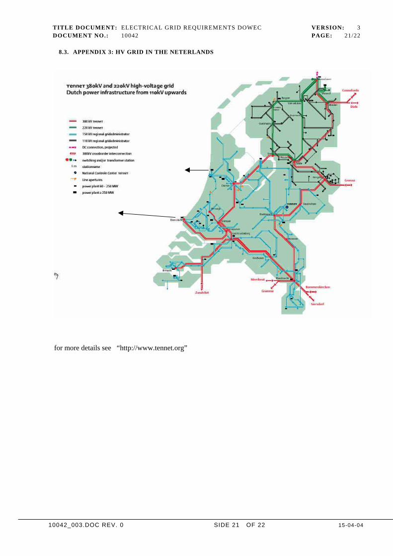
8.3. APPENDIX 3: HV GRID IN THE NETERLANDS
for more details see “http://www.tennet.org”
TITLE DOCUMENT: ELECTRICAL GRID REQUIREMENTS DOWEC VERSION: 3DOCUMENT NO.: 10042 PAGE: 22/22
10042_003.DOC REV. 0 SIDE 22 OF 22 15-04-04
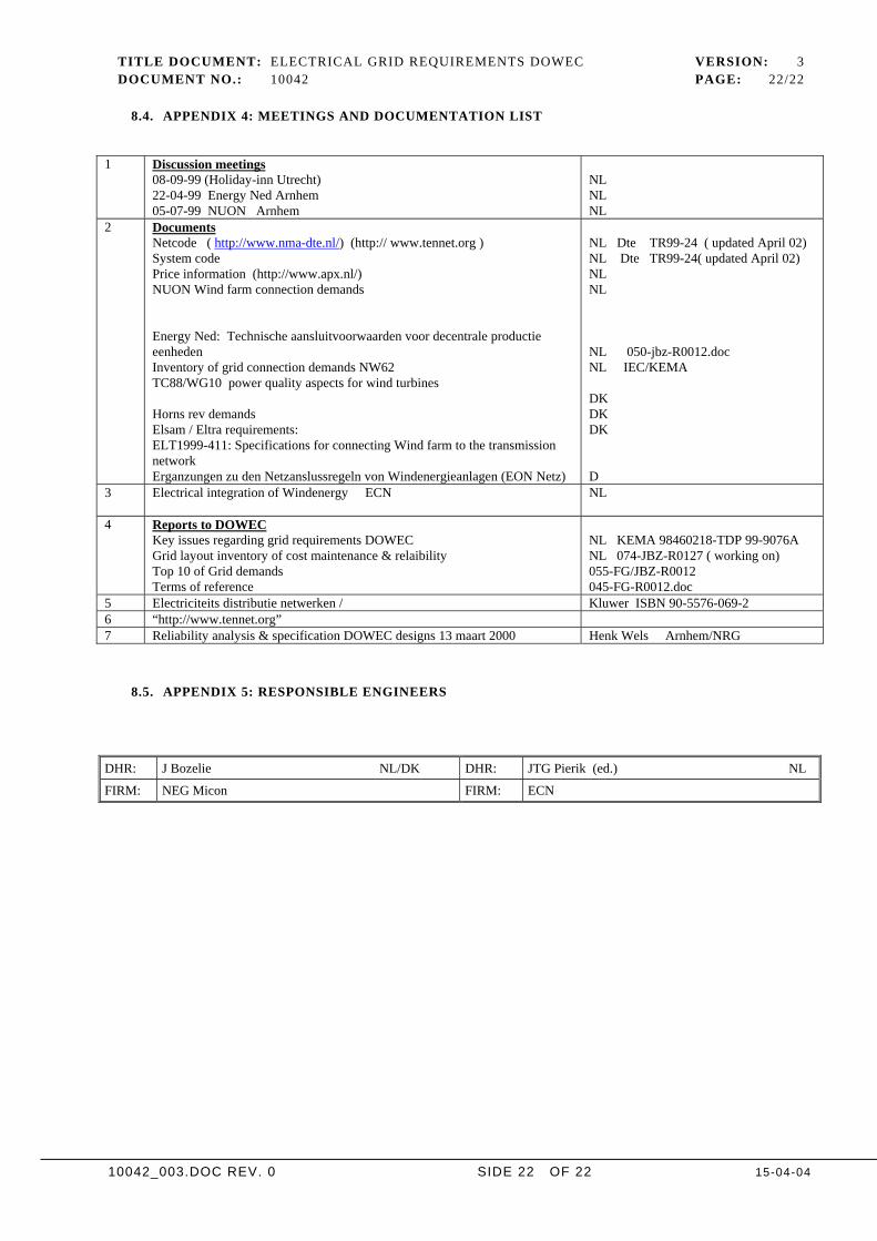
8.4. APPENDIX 4: MEETINGS AND DOCUMENTATION LIST
1 Discussion meetings08-09-99 (Holiday-inn Utrecht)22-04-99 Energy Ned Arnhem05-07-99 NUON Arnhem
NLNLNL
2 DocumentsNetcode ( http://www.nma-dte.nl/) (http:// www.tennet.org )System codePrice information (http://www.apx.nl/)NUON Wind farm connection demands
Energy Ned: Technische aansluitvoorwaarden voor decentrale productieeenhedenInventory of grid connection demands NW62TC88/WG10 power quality aspects for wind turbines
Horns rev demandsElsam / Eltra requirements:ELT1999-411: Specifications for connecting Wind farm to the transmissionnetworkErganzungen zu den Netzanslussregeln von Windenergieanlagen (EON Netz)
NL Dte TR99-24 ( updated April 02)NL Dte TR99-24( updated April 02)NLNL
NL 050-jbz-R0012.docNL IEC/KEMA
DKDKDK
D3 Electrical integration of Windenergy ECN NL
4 Reports to DOWECKey issues regarding grid requirements DOWECGrid layout inventory of cost maintenance & relaibilityTop 10 of Grid demandsTerms of reference
NL KEMA 98460218-TDP 99-9076ANL 074-JBZ-R0127 ( working on)055-FG/JBZ-R0012045-FG-R0012.doc
5 Electriciteits distributie netwerken / Kluwer ISBN 90-5576-069-26 “http://www.tennet.org”7 Reliability analysis & specification DOWEC designs 13 maart 2000 Henk Wels Arnhem/NRG
8.5. APPENDIX 5: RESPONSIBLE ENGINEERS
DHR: J Bozelie NL/DK DHR: JTG Pierik (ed.) NL
FIRM: NEG Micon FIRM: ECN