electric torque vectoring for electric vehicles
TRANSCRIPT
ELECTRIC TORQUE VECTORING FOR ELECTRIC VEHICLES
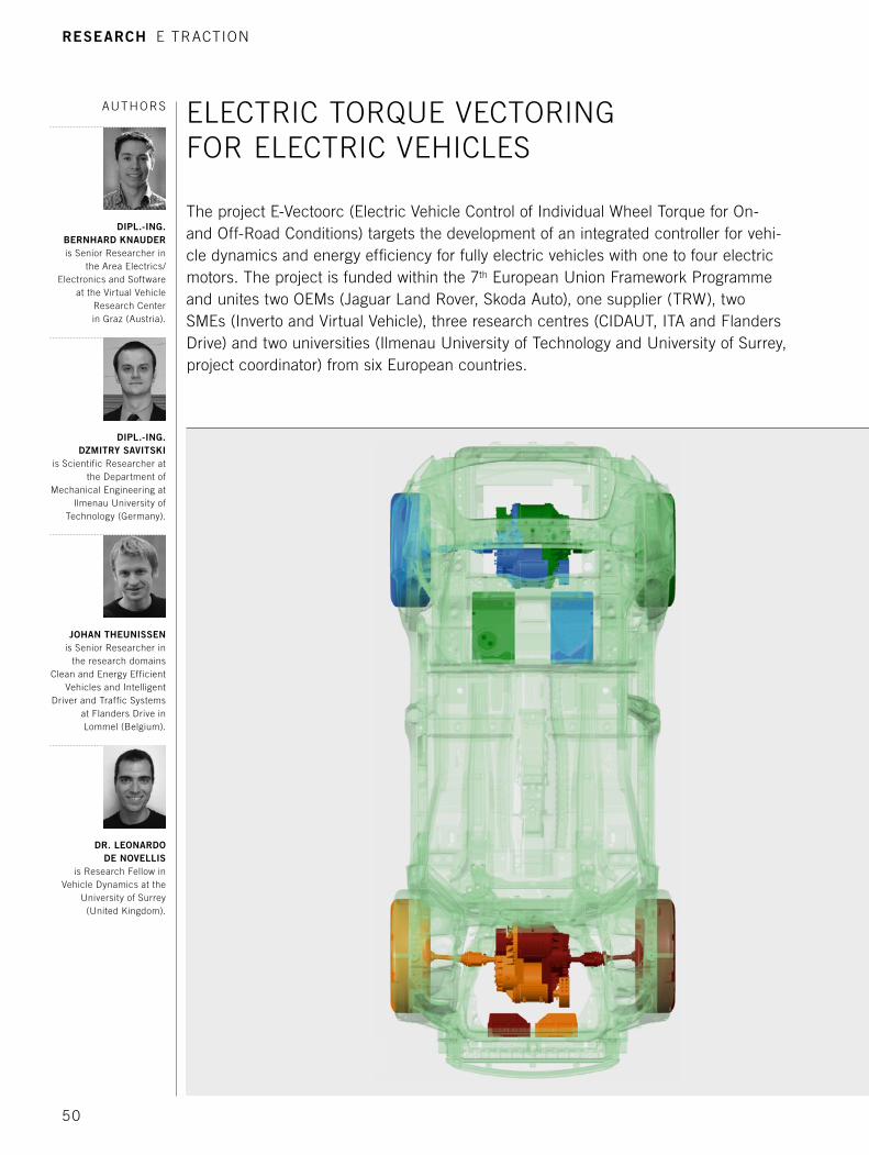
The project E-Vectoorc (Electric Vehicle Control of Individual Wheel Torque for On- and Off-Road Conditions) targets the development of an integrated controller for vehi-cle dynamics and energy efficiency for fully electric vehicles with one to four electric motors. The project is funded within the 7th European Union Framework Programme and unites two OEMs (Jaguar Land Rover, Skoda Auto), one supplier (TRW), two SMEs (Inverto and Virtual Vehicle), three research centres (CIDAUT, ITA and Flanders Drive) and two universities (Ilmenau University of Technology and University of Surrey, project coordinator) from six European countries.
AUTHORS
DIPL.-ING. BERNHARD KNAUDERis Senior Researcher in
the Area Electrics/ Electronics and Software
at the Virtual Vehicle Research Center in Graz (Austria).
DIPL.-ING. DZMITRY SAVITSKI
is Scientific Researcher at the Department of
Mechanical Engineering at Ilmenau University of
Technology (Germany).
JOHAN THEUNISSENis Senior Researcher in
the research domains Clean and Energy Efficient
Vehicles and Intelligent Driver and Traffic Systems
at Flanders Drive in Lommel (Belgium).
DR. LEONARDO DE NOVELLIS
is Research Fellow in Vehicle Dynamics at the
University of Surrey (United Kingdom).
RESEARCH E TRACTION
50
E traction
1 TORQUE VECTORING
For the automotive industry, torque vectoring (TV) is a modern concept to enhance driving stability and safety whilst improving vehicle dynamics or the fun-to-drive. TV offers the capability of individual wheel torque distribution and has a direct impact on the vehicle’s yaw moment. In conventional powertrain architectures, vehicle stability control is typically based on friction brakes, whereas TV differentials are rare because of their complexity and – as a result – higher costs. Electric vehicle architectures with individual wheel propulsion devices on the other allow for selec-tive torque distribution. Next to the positive vehicle handling and safety features of torque vectoring an efficient operation is required to extend the operational range of the electric vehicle.
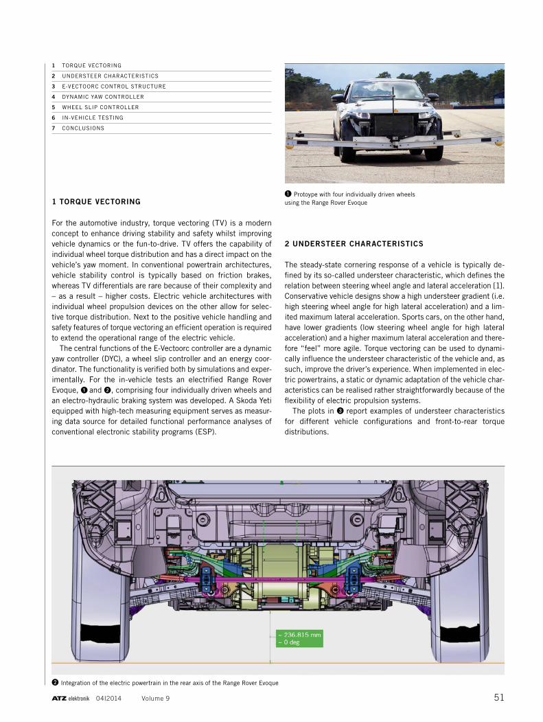
The central functions of the E-Vectoorc controller are a dynamic yaw controller (DYC), a wheel slip controller and an energy coor-dinator. The functionality is verified both by simulations and exper-imentally. For the in-vehicle tests an electrified Range Rover Evoque, ➊ and ➋, comprising four individually driven wheels and an electro-hydraulic braking system was developed. A Skoda Yeti equipped with high-tech measuring equipment serves as measur-ing data source for detailed functional performance analyses of conventional electronic stability programs (ESP).
2 UNDERSTEER CHARACTERISTICS
The steady-state cornering response of a vehicle is typically de -fined by its so-called understeer characteristic, which defines the relation between steering wheel angle and lateral acceleration [1]. Conservative vehicle designs show a high understeer gradient (i.e. high steering wheel angle for high lateral acceleration) and a lim-ited maximum lateral acceleration. Sports cars, on the other hand, have lower gradients (low steering wheel angle for high lateral acceleration) and a higher maximum lateral acceleration and there-fore “feel” more agile. Torque vectoring can be used to dynami-cally influence the understeer characteristic of the vehicle and, as such, improve the driver’s experience. When implemented in elec-tric powertrains, a static or dynamic adaptation of the vehicle char-acteristics can be realised rather straightforwardly because of the flexibility of electric propulsion systems.
The plots in ❸ report examples of understeer characteristics for different vehicle configurations and front-to-rear torque distributions.
1 TORQUE VECTORING
2 UNDERSTEER CHARACTERISTICS
3 E-VECTOORC CONTROL STRUCTURE
4 DYNAMIC YAW CONTROLLER
5 WHEEL SLIP CONTROLLER
6 IN-VEHICLE TESTING
7 CONCLUSIONS
❶ Protoype with four individually driven wheels using the Range Rover Evoque
❷ Integration of the electric powertrain in the rear axis of the Range Rover Evoque
51 04I2014 Volume 9
E traction
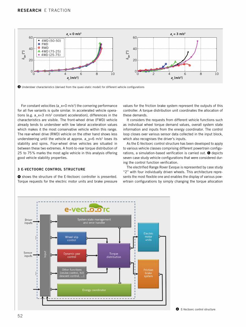
For constant velocities (a_x=0 m/s2) the cornering performance for all five variants is quite similar. In accelerated vehicle opera-tions (e.g. a_x=3 m/s2 constant acceleration), differences in the characteristics are visible. The front-wheel drive (FWD) vehicle already tends to understeer with low lateral acceleration values which makes it the most conservative vehicle within this range. The rear-wheel drive (RWD) vehicle on the other hand shows less understeering until the vehicle at approx. a_y=6 m/s2 loses its stability and spins. Four-wheel drive vehicles are situated in between these two extremes. A front-to-rear torque distribution of 25 to 75 % marks the most agile vehicle in this analysis offering good vehicle stability properties.
3 E-VECTOORC CONTROL STRUCTURE
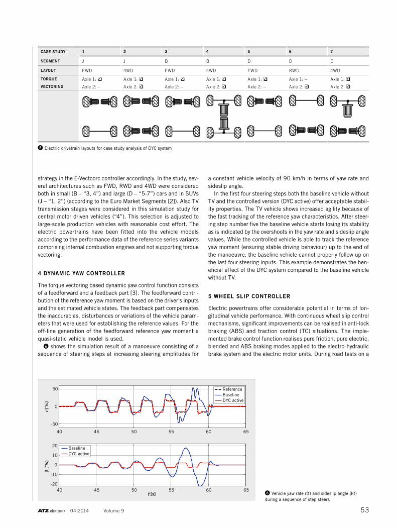
➍ shows the structure of the E-Vectoorc controller is presented. Torque requests for the electric motor units and brake pressure
values for the friction brake system represent the outputs of this controller. A torque distribution unit coordinates the allocation of these demands.
It considers the requests from different vehicle functions such as individual wheel torque demand values, overall system state information and inputs from the energy coordinator. The control loop closes over various sensor data collected in the input block, which also recognises the driver’s inputs.
As the E-Vectoorc control structure has been developed to apply to various vehicle classes comprising different powertrain configu-rations, a simulation-based verification is carried out. ❺ depicts seven case study vehicle configurations that were considered dur-ing the control function verification.
The electrified Range Rover Evoque is represented by case study “2” with four individually driven wheels. This architecture repre-sents the most flexible one and enables the display of various pow-ertrain configurations by simply changing the torque allocation
0 2 4 6 8 100
20
40
60
ay [m/s2]
δ dyn [
°]
ax = 0 m/s2
0 2 4 6 8 100
20
40
60
ay [m/s2]
δ dyn [
°]
ax = 3 m/s2
4WD (50-50)FWDRWD4WD (75-25)
4WD (25-75)
❸ Understeer characteristics (derived from the quasi-static model) for different vehicle configurations
❹ E-Vectoorc control structure
RESEARCH E TRACTION
52
strategy in the E-Vectoorc controller accordingly. In the study, sev-eral architectures such as FWD, RWD and 4WD were considered both in small (B – “3, 4”) and large (D – “5-7”) cars and in SUVs (J – “1, 2”) (according to the Euro Market Segments [2]). Also TV transmission stages were considered in this simulation study for central motor driven vehicles (“4”). This selection is adjusted to large-scale production vehicles with reasonable cost effort. The electric powertrains have been fitted into the vehicle models according to the performance data of the reference series variants comprising internal combustion engines and not supporting torque vectoring.
4 DYNAMIC YAW CONTROLLER
The torque vectoring based dynamic yaw control function consists of a feedforward and a feedback part [3]. The feedforward contri-bution of the reference yaw moment is based on the driver’s inputs and the estimated vehicle states. The feedback part compensates the inaccuracies, disturbances or variations of the vehicle param-eters that were used for establishing the reference values. For the off-line generation of the feedforward reference yaw moment a quasi-static vehicle model is used.
❻ shows the simulation result of a manoeuvre consisting of a sequence of steering steps at increasing steering amplitudes for
a constant vehicle velocity of 90 km/h in terms of yaw rate and sideslip angle.
In the first four steering steps both the baseline vehicle without TV and the controlled version (DYC active) offer acceptable stabil-ity properties. The TV vehicle shows increased agility because of the fast tracking of the reference yaw characteristics. After steer-ing step number five the baseline vehicle starts losing its stability as is indicated by the overshoots in the yaw rate and sideslip angle values. While the controlled vehicle is able to track the reference yaw moment (ensuring stable driving behaviour) up to the end of the manoeuvre, the baseline vehicle cannot properly follow up on the last four steering inputs. This example demonstrates the ben-eficial effect of the DYC system compared to the baseline vehicle without TV.
5 WHEEL SLIP CONTROLLER
Electric powertrains offer considerable potential in terms of lon-gitudinal vehicle performance. With continuous wheel slip control mechanisms, significant improvements can be realised in anti-lock braking (ABS) and traction control (TC) situations. The imple-mented brake control function realises pure friction, pure electric, blended and ABS braking modes applied to the electro-hydraulic brake system and the electric motor units. During road tests on a
❺ Electric drivetrain layouts for case study analysis of DYC system
CASE STUDY 1 2 3 4 5 6 7
SEGMENT J J B B D D D
LAYOUT FWD 4WD FWD 4WD FWD RWD 4WD
TORQUE
VECTORING
Axle 1: ❑✓
Axle 2: –
Axle 1: ❑✓
Axle 2: ❑✓
Axle 1: ❑✓
Axle 2: –
Axle 1: ❑✓
Axle 2: ❑✓
Axle 1: ❑✓
Axle 2: –
Axle 1: –
Axle 2: ❑✓
Axle 1: ❑✗
Axle 2: ❑✓
40 45 50 55 60 65
-50
0
50
r [°
/s]
β [°
/s]
ReferenceBaselineDYC active
40 45 50 55 60 65-20
-10
0
10
20
t [s]
BaselineDYC active
❻ Vehicle yaw rate r(t) and sideslip angle β(t) during a sequence of step steers
53 04I2014 Volume 9
low-µ surface the application of the direct slip control resulted in a brake distance reduction of up to 28.8 % compared to braking without ABS and of 14.6 % compared to braking with standard ABS utilising only the friction brake system.
6 IN-VEHICLE TESTING
The proof of concept is achieved through vehicle tests with the Range Rover Evoque performed at the Lommel proving ground (Belgium). The visual of this article shows the vehicle equipped for vehicle dynamics tests. Its modular concept consists of two identical powertrain units, each containing two electric motors. One of these units is installed at the front and one at the rear axle of the vehicle. Via single-speed, two-stage reduction boxes the switched reluctance (SR) motor units are connected over the half-shafts to the wheels. The benefits of using SR motors for automo-tive applications are their robust performance, a long constant
power region and high speed operation. The absence of permanent magnets makes the SR motor more cost-effective. The energy for the powertrain is provided by a 600 V battery pack with a capac-ity of 9 kWh feeding 3-phase inverter units. The test vehicle com-prising four electric motors offers a total system power of 140 kW (400 kW peak for max. 30 s) and a total torque of 320 Nm torque (800 Nm peak for max. 30 s).
The E-Vectoorc structure is implemented as a chassis controller incorporating control functions with regard to basic drivability, energy and system management, dynamic yaw control, wheel slip control, torque distribution via control allocation and a brake blending strategy.
Considering the hazards that may arise in electric powertrains and their controllers, a functional safety concept according to ISO 26262 [4] is elaborated. Resulting measures such as feasibility checks in the torque actuation path are integrated into the E-Vec-toorc controller structure to ensure safe vehicle operation.
0 1 2 3 4 5 6 7 8 9 1030
40
50
60
70
80
90
ay [m/s2]
δ [°
]
Sport modeNormal mode
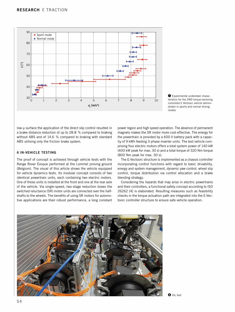
❼ Experimental understeer charac-teristics for the 2WD torque-vectoring controlled E Vectoorc vehicle demon-strator in sports and normal driving modes
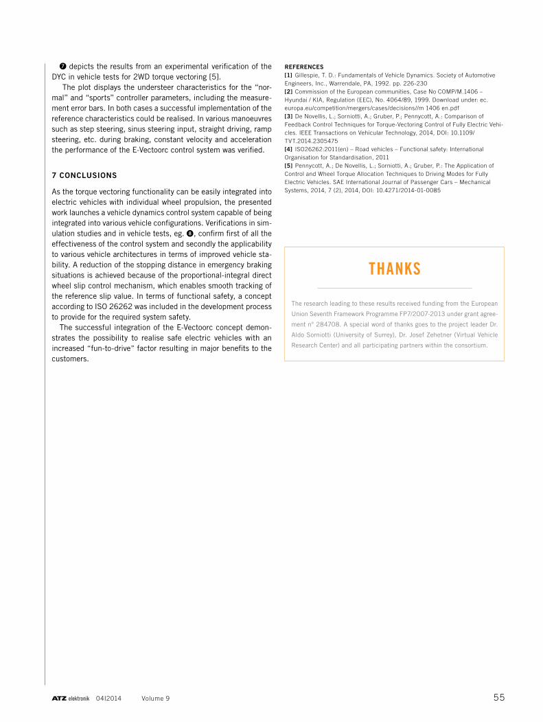
❽ HiL test
RESEARCH E TRACTION
54
❼ depicts the results from an experimental verification of the DYC in vehicle tests for 2WD torque vectoring [5].
The plot displays the understeer characteristics for the “nor-mal” and “sports” controller parameters, including the measure-ment error bars. In both cases a successful implementation of the reference characteristics could be realised. In various manoeuvres such as step steering, sinus steering input, straight driving, ramp steering, etc. during braking, constant velocity and acceleration the performance of the E-Vectoorc control system was verified.
7 CONCLUSIONS
As the torque vectoring functionality can be easily integrated into electric vehicles with individual wheel propulsion, the presented work launches a vehicle dynamics control system capable of being integrated into various vehicle configurations. Verifications in sim-ulation studies and in vehicle tests, eg. ➑, confirm first of all the effectiveness of the control system and secondly the applicability to various vehicle architectures in terms of improved vehicle sta-bility. A reduction of the stopping distance in emergency braking situations is achieved because of the proportional-integral direct wheel slip control mechanism, which enables smooth tracking of the reference slip value. In terms of functional safety, a concept according to ISO 26262 was included in the development process to provide for the required system safety.
The successful integration of the E-Vectoorc concept demon-strates the possibility to realise safe electric vehicles with an increased “fun-to-drive” factor resulting in major benefits to the customers.
REFERENCES[1] Gillespie, T. D.: Fundamentals of Vehicle Dynamics. Society of Automotive Engineers, Inc., Warrendale, PA, 1992. pp. 226-230[2] Commission of the European communities, Case No COMP/M.1406 – Hyundai / KIA, Regulation (EEC), No. 4064/89, 1999. Download under: ec.europa.eu/competition/mergers/cases/decisions//m 1406 en.pdf[3] De Novellis, L.; Sorniotti, A.; Gruber, P.; Pennycott, A.: Comparison of Feedback Control Techniques for Torque-Vectoring Control of Fully Electric Vehi-cles. IEEE Transactions on Vehicular Technology, 2014, DOI: 10.1109/TVT.2014.2305475[4] ISO26262:2011(en) – Road vehicles – Functional safety: International Organisation for Standardisation, 2011[5] Pennycott, A.; De Novellis, L.; Sorniotti, A.; Gruber, P.: The Application of Control and Wheel Torque Allocation Techniques to Driving Modes for Fully Electric Vehicles. SAE International Journal of Passenger Cars – Mechanical Systems, 2014, 7 (2), 2014, DOI: 10.4271/2014-01-0085
❽ HiL test
THANKS
The research leading to these results received funding from the European
Union Seventh Framework Programme FP7/2007-2013 under grant agree-
ment n° 284708. A special word of thanks goes to the project leader Dr.
Aldo Sorniotti (University of Surrey), Dr. Josef Zehetner (Virtual Vehicle
Research Center) and all participating partners within the consortium.
55 04I2014 Volume 9