electric field lines …... electric field lines recall that we defined the electric field to be the...
TRANSCRIPT
ELECTRIC FIELD LINES …..
ELEC 3105 Lecture 2
Electric field lines
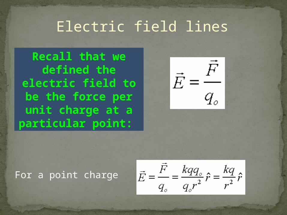
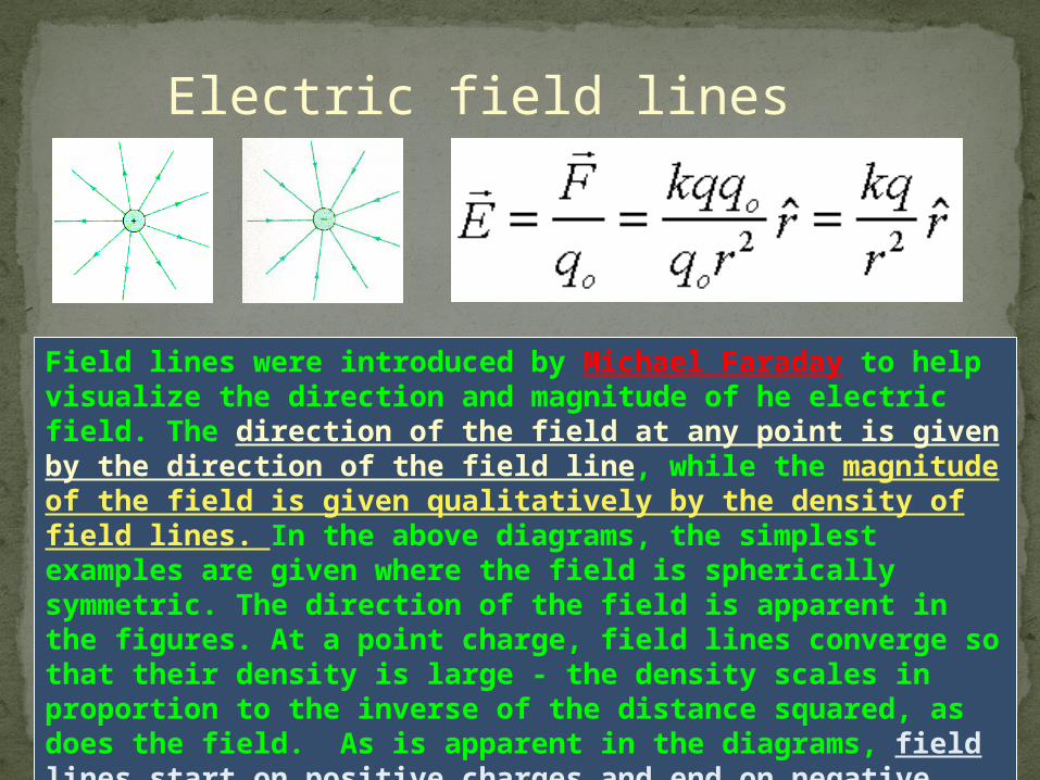
Recall that we defined the electric field to be the
force per unit charge at a particular point:
For a point charge
Electric field lines
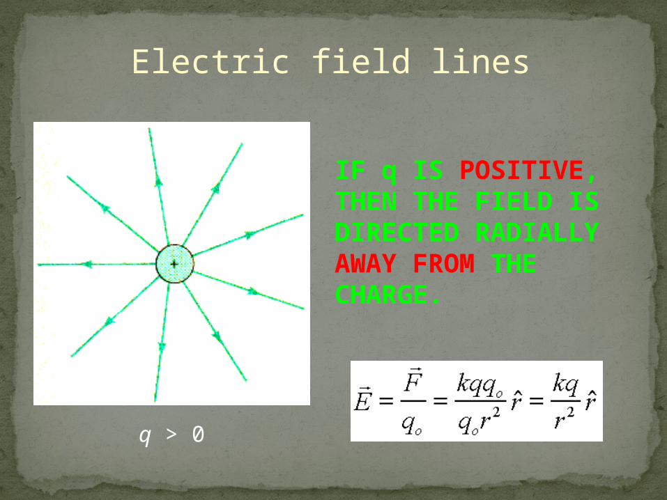
IF q IS POSITIVE, THEN THE FIELD IS DIRECTED RADIALLY AWAY FROM THE CHARGE.
q > 0
Electric field lines
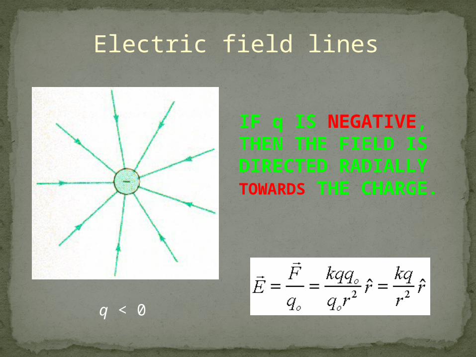
IF q IS NEGATIVE, THEN THE FIELD IS DIRECTED RADIALLY TOWARDS THE CHARGE.
q < 0
Electric field lines
Field lines were introduced by Michael Faraday to help visualize the direction and magnitude of he electric field. The direction of the field at any point is given by the direction of the field line, while the magnitude of the field is given qualitatively by the density of field lines. In the above diagrams, the simplest examples are given where the field is spherically symmetric. The direction of the field is apparent in the figures. At a point charge, field lines converge so that their density is large - the density scales in proportion to the inverse of the distance squared, as does the field. As is apparent in the diagrams, field lines start on positive charges and end on negative charges. This is all convention, but it nonetheless useful to remember.
Electric field lines
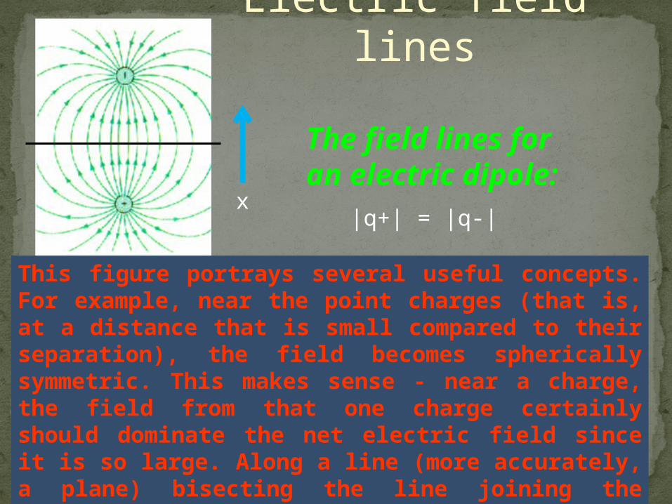
This figure portrays several useful concepts. For example, near the point charges (that is, at a distance that is small compared to their separation), the field becomes spherically symmetric. This makes sense - near a charge, the field from that one charge certainly should dominate the net electric field since it is so large. Along a line (more accurately, a plane) bisecting the line joining the charges, we see that the field is directed along the -x direction as shown.
The field lines for an electric dipole:
x|q+| = |q-|
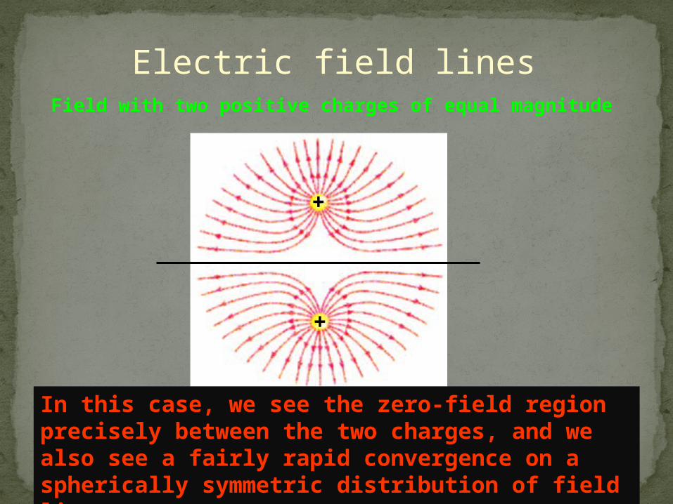
Electric field linesField with two positive charges of equal magnitude
In this case, we see the zero-field region precisely between the two charges, and we also see a fairly rapid convergence on a spherically symmetric distribution of field lines.
+
+
Electric field lines
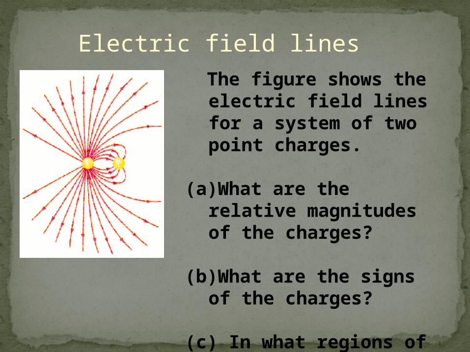
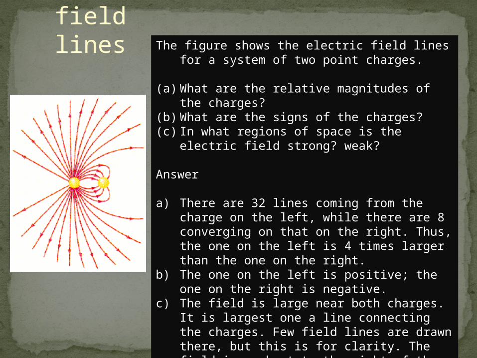
The figure shows the electric field lines for a system of two point charges.
(a)What are the relative magnitudes of the charges?
(b)What are the signs of the charges?
(c) In what regions of space is the electric field strong? weak
Electric field lines The figure shows the electric field lines for a system of two
point charges.
(a) What are the relative magnitudes of the charges?(b) What are the signs of the charges?(c) In what regions of space is the electric field strong?
weak?
Answer
a) There are 32 lines coming from the charge on the left, while there are 8 converging on that on the right. Thus, the one on the left is 4 times larger than the one on the right.
b) The one on the left is positive; the one on the right is negative.
c) The field is large near both charges. It is largest one a line connecting the charges. Few field lines are drawn there, but this is for clarity. The field is weakest to the right of the right hand charge.
Electric field lines
Electric field lines
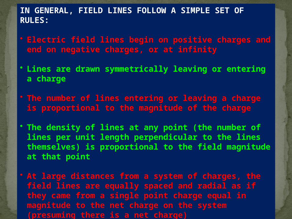
IN GENERAL, FIELD LINES FOLLOW A SIMPLE SET OF RULES: • Electric field lines begin on positive charges and end on negative
charges, or at infinity
• Lines are drawn symmetrically leaving or entering a charge
• The number of lines entering or leaving a charge is proportional to the magnitude of the charge
• The density of lines at any point (the number of lines per unit length perpendicular to the lines themselves) is proportional to the field magnitude at that point
• At large distances from a system of charges, the field lines are equally spaced and radial as if they came from a single point charge equal in magnitude to the net charge on the system (presuming there is a net charge)
• No two field lines can cross since the field magnitude and direction must be unique.
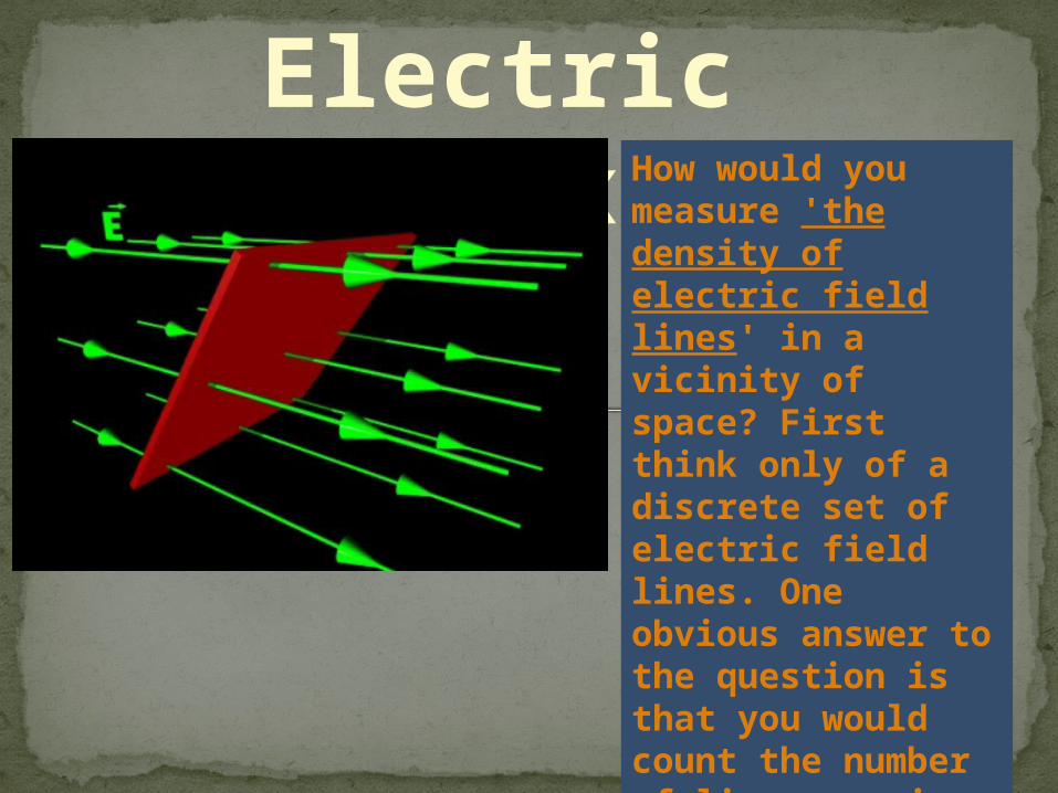
Electric FluxHow would you measure 'the density of electric field lines' in a vicinity of space? First think only of a discrete set of electric field lines. One obvious answer to the question is that you would count the number of lines passing through an imaginary geometrical (not real!) surface.

Electric FluxThe number of field lines passing through a geometrical surface of given area depends on three things: the field strength (E), the area (A), and the orientation of the surface (). The first two are obvious, and the following diagram will indicate the last:
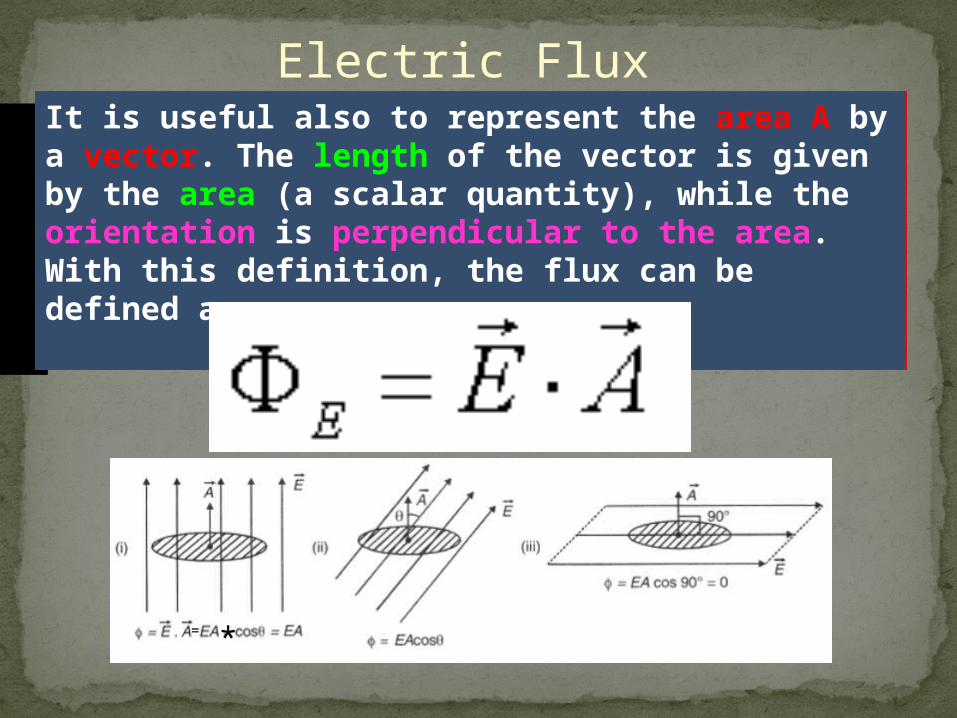
Electric FluxIt is useful also to represent the area A by a vector. The length of the vector is given by the area (a scalar quantity), while the orientation is perpendicular to the area. With this definition, the flux can be defined as:
= *
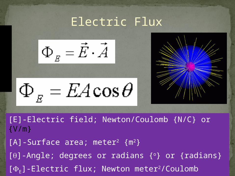
Electric Flux
[E]-Electric field; Newton/Coulomb {N/C} or {V/m}
[A]-Surface area; meter2 {m2}
[]-Angle; degrees or radians {o} or {radians}
[E]-Electric flux; Newton meter2/Coulomb {Nm2/C} or {Vm/C}
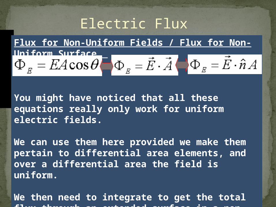
Electric FluxFlux for Non-Uniform Fields / Flux for Non-Uniform Surface
You might have noticed that all these equations really only work for uniform electric fields.
We can use them here provided we make them pertain to differential area elements, and over a differential area the field is uniform.
We then need to integrate to get the total flux through an extended surface in a non-uniform field.
Electric Flux
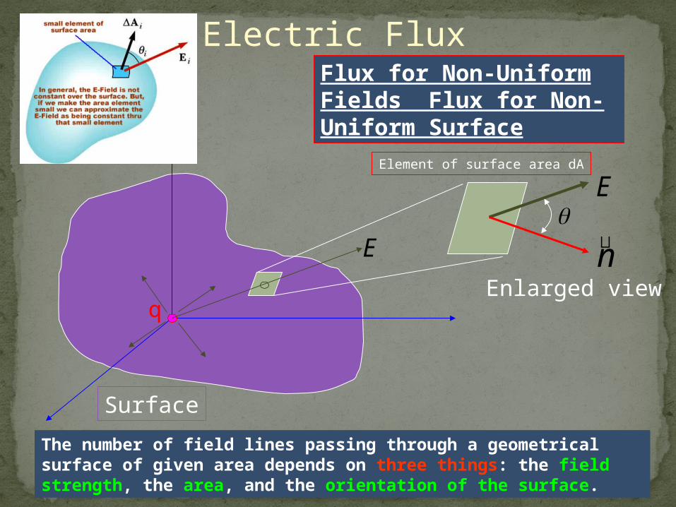
The number of field lines passing through a geometrical surface of given area depends on three things: the field strength, the area, and the orientation of the surface.
Flux for Non-Uniform Fields Flux for Non-Uniform Surface
q
E
Surface
E
n
Element of surface area dA
Enlarged view
Electric Flux
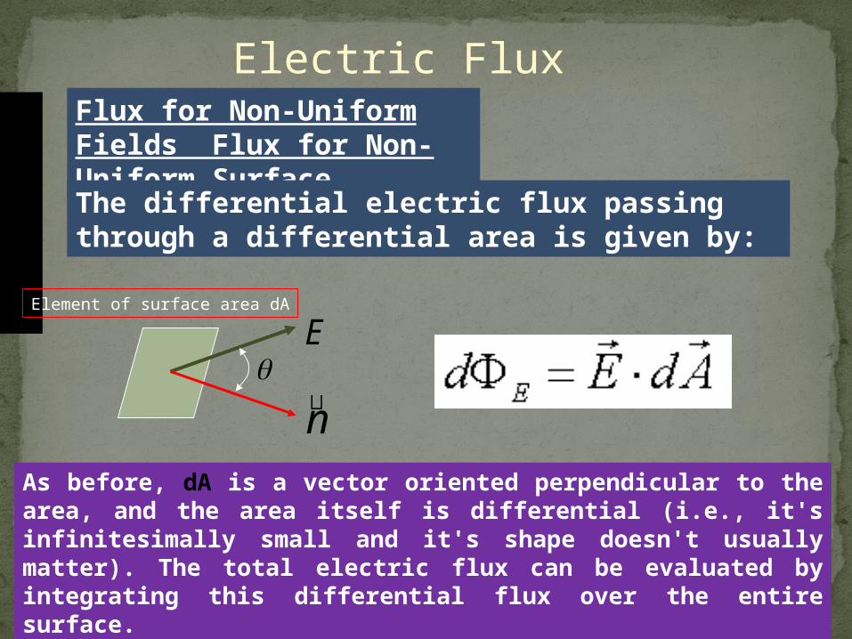
As before, dA is a vector oriented perpendicular to the area, and the area itself is differential (i.e., it's infinitesimally small and it's shape doesn't usually matter). The total electric flux can be evaluated by integrating this differential flux over the entire surface.
Flux for Non-Uniform Fields Flux for Non-Uniform Surface
E
n
Element of surface area dA
The differential electric flux passing through a differential area is given by:
Electric Flux
q
ESurface
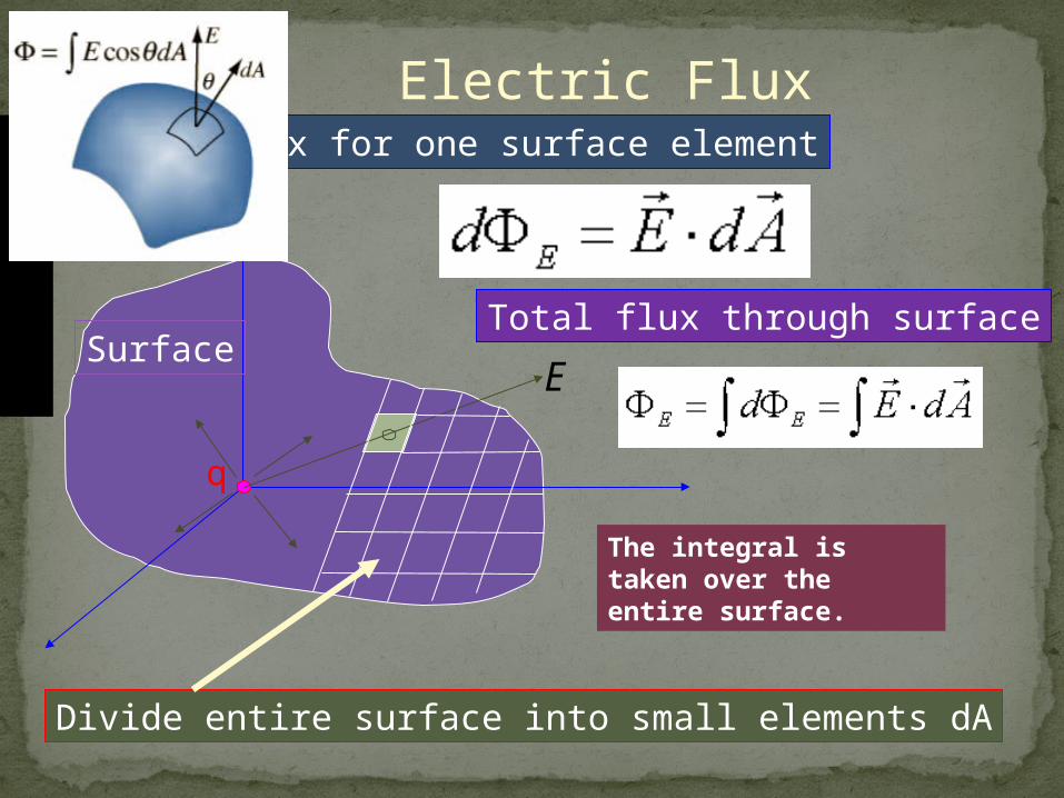
Divide entire surface into small elements dA
Flux for one surface element
The integral is taken over the entire surface.
Total flux through surface
Electric Flux
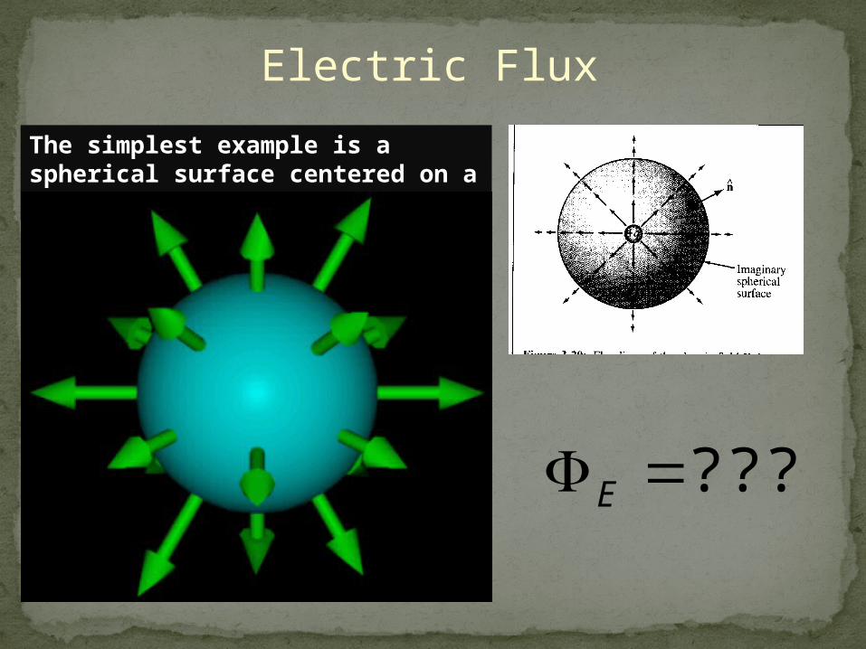
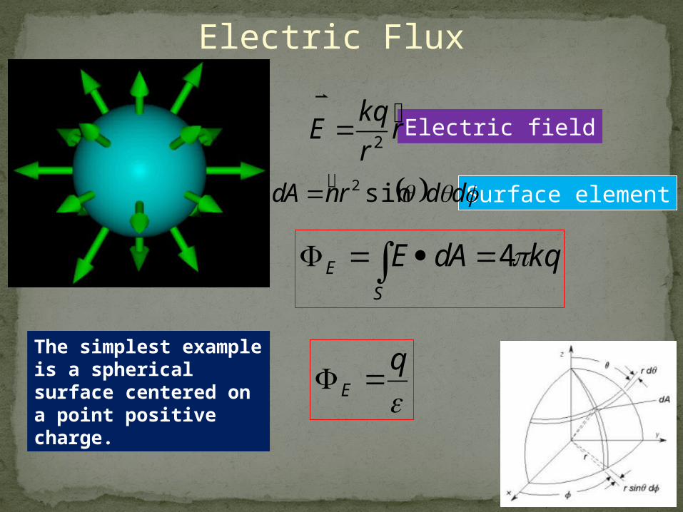
The simplest example is a spherical surface centered on a point positive charge.
????E
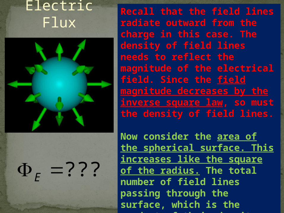
Electric FluxRecall that the field lines radiate outward from the charge in this case. The density of field lines needs to reflect the magnitude of the electrical field. Since the field magnitude decreases by the inverse square law, so must the density of field lines.
Now consider the area of the spherical surface. This increases like the square of the radius. The total number of field lines passing through the surface, which is the product of their density and the area of the surface, must then be independent of the size of the sphere. The number of field lines is directly related to the size of the charge at the center of the sphere.
????E
Electric Flux
The simplest example is a spherical surface centered on a point positive charge.
rr
kqE
2
Electric field
ddrnAd sin2 Surface element
kqAdES
E 4
q
E
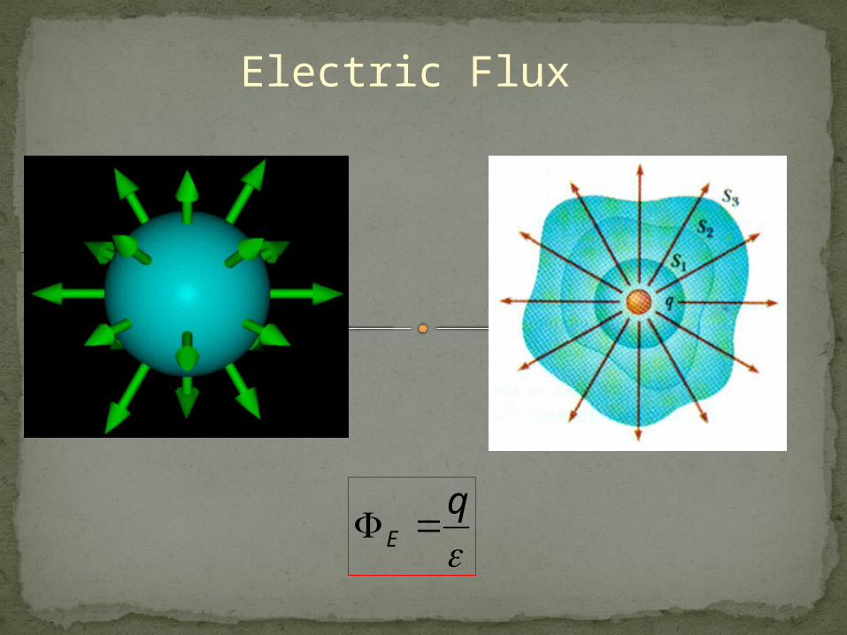
q
E
Electric Flux
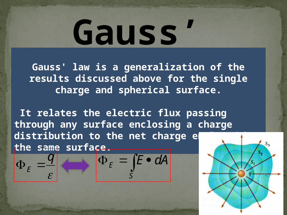
Gauss’ lawGauss' law is a generalization of the results discussed above
for the single charge and spherical surface.
It relates the electric flux passing through any surface enclosing a charge distribution to the net charge enclosed by the same surface.
S
E AdE
q
E
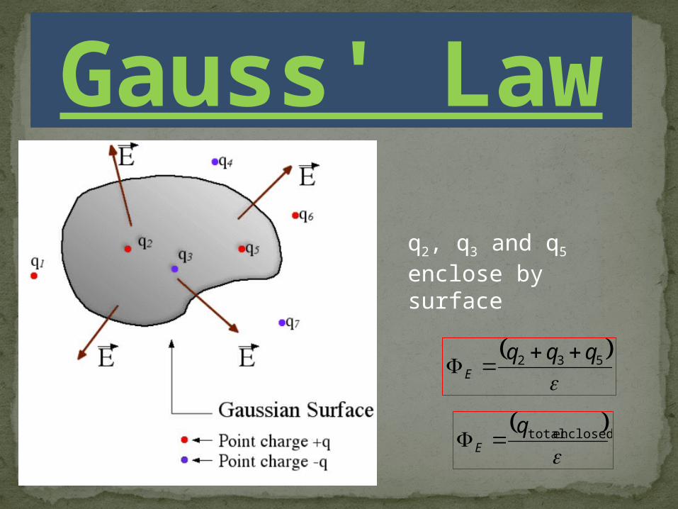
Gauss' Law
q2, q3 and q5 enclose by surface
532 qqqE
enclosed totalq
E
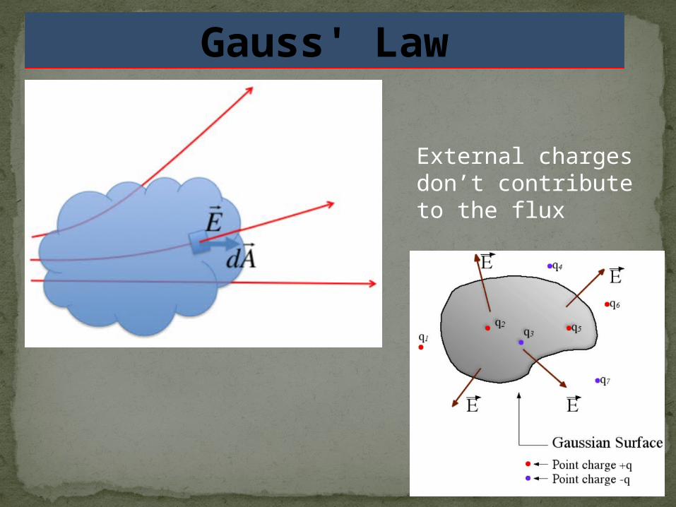
Gauss' Law
External charges don’t contribute to the flux
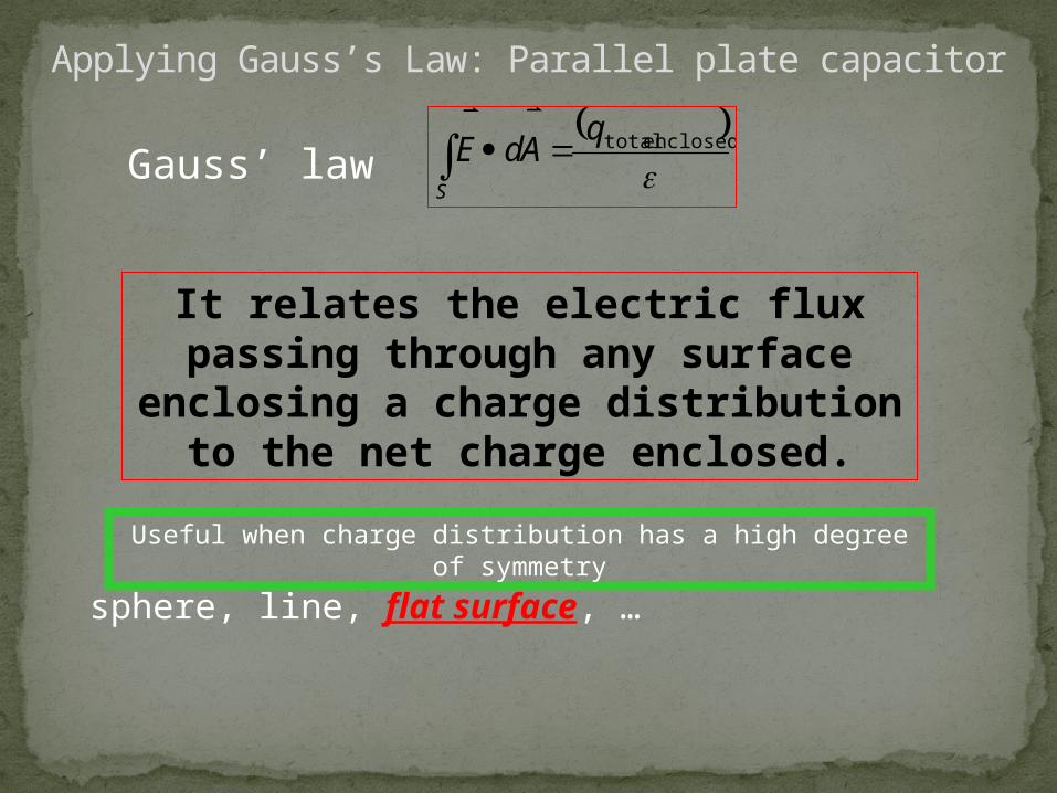
Applying Gauss’s Law: Parallel plate capacitor
It relates the electric flux passing through any surface enclosing a charge distribution
to the net charge enclosed.
Useful when charge distribution has a high degree of symmetry
sphere, line, flat surface, …
enclosed totalq
AdES
Gauss’ law
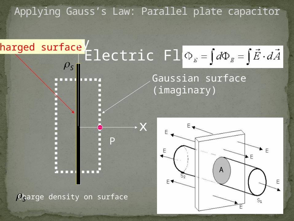
Charged surface
Gaussian surface (imaginary)
P
Electric Flux
x
y
S
S Charge density on surface
Applying Gauss’s Law: Parallel plate capacitor
A

• E Perpendicular to charged surface.
• No flux through sides of Gaussian cylinder.
Applying Gauss’s Law: Parallel plate capacitor
A
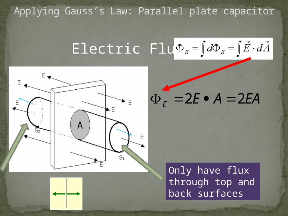
Electric Flux
EAAEE 22
Applying Gauss’s Law: Parallel plate capacitor
Only have flux through top and back surfaces
A
Electric Flux
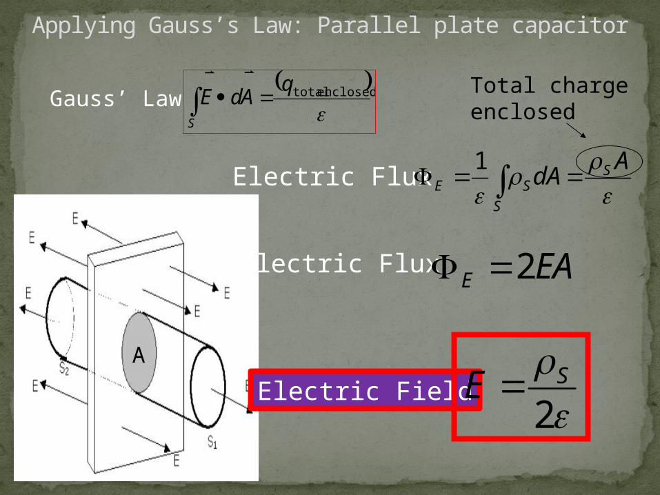
enclosed totalq
AdES
A
dA S
S
SE 1
Total chargeenclosed
Applying Gauss’s Law: Parallel plate capacitor
Gauss’ Law
Electric Flux EAE 2
A
2SE Electric Field
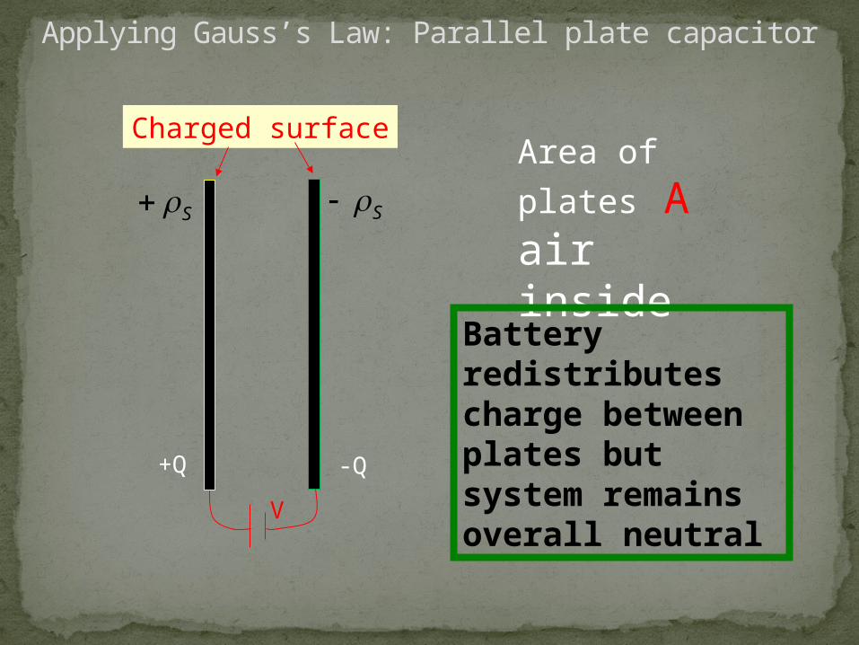
Charged surface
S SArea of plates Aair inside
+Q -Q
V
Battery redistributes charge between plates but system remains overall neutral
Applying Gauss’s Law: Parallel plate capacitor
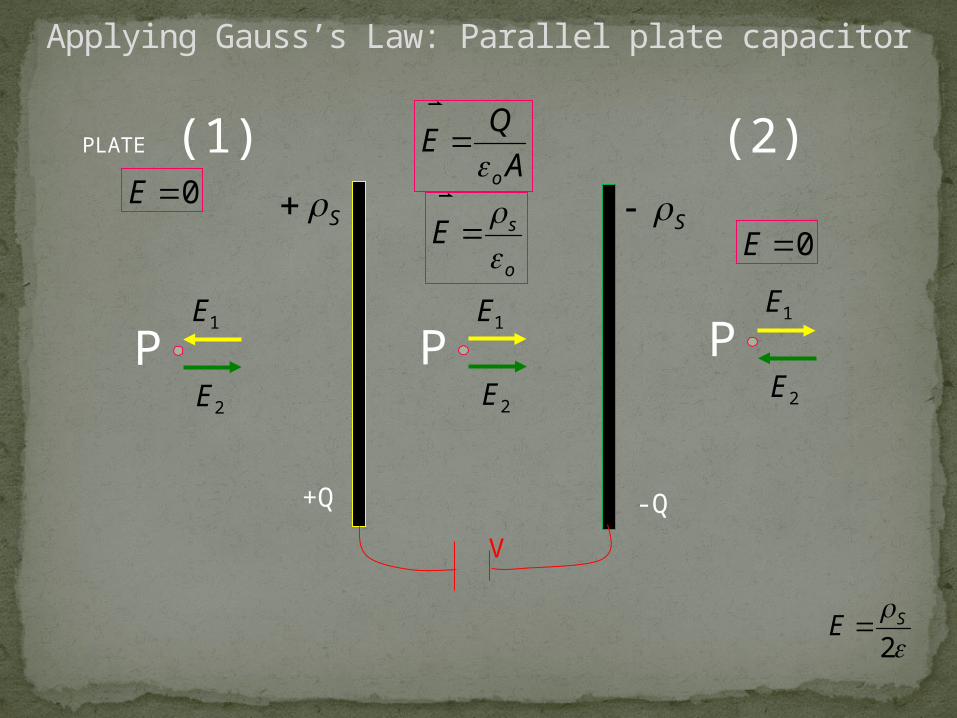
A
QE
o
o
sE
S
+Q
S
-Q
V
P1E
2E
PLATE (1) (2)0E
0E
P1E
2EP
1E
2E
Applying Gauss’s Law: Parallel plate capacitor
2SE
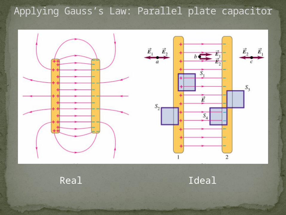
Applying Gauss’s Law: Parallel plate capacitor
Real Ideal
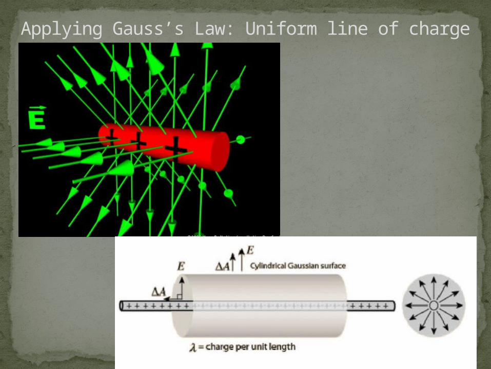
Applying Gauss’s Law: Uniform line of charge
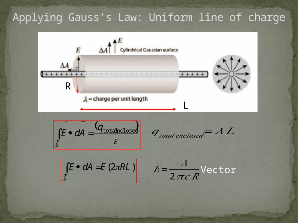
Applying Gauss’s Law: Uniform line of charge
𝐸=𝜆
2𝜋𝜖 𝑅
𝑞𝑡𝑜𝑡𝑎𝑙 𝑒𝑛𝑐𝑙𝑜𝑠𝑒𝑑=𝜆𝐿 enclosed totalq
AdES
)2( RLEAdES
R
L
Vector

ELECTRIC FIELD LINES …..
ELEC 3105 Lecture 2