electra elite ipk features and specifications manual ... elite ipk features and...e-9 elite...
TRANSCRIPT

NOTICE
Note that when converting this document from its original format to a .pdf file, some minor font and format changes may occur causing slight variations. When viewing and printing this document, we cannot guarantee that your specific PC or printer will support all of the fonts or graphics. Therefore, when you view the document fonts may be substituted and your individual printer may not have the capability to print the document correctly.
Features and Specifications Manual
INT-1023 (IPK)
Document Revision 4
(Release 4000/4500)

NEC Unified Solutions, Inc. reserves the right to change the specifications, functions, or features at any time without notice.
NEC Unified Solutions, Inc. has prepared this document for use by its employees and customers. The information contained herein is the property of NEC Unified Solutions, Inc. and shall not be reproduced without prior written approval of NEC Unified Solutions, Inc.
Dterm is a registered trademark of NEC Corporation and Electra Elite is a registered trademark of NEC America, Inc. Windows is a registered trademark of Microsoft Corporation. TeLANophy, ViewMail, ViewCall Plus, ActiveFax, and ViewFax are all registered trademarks of Active Voice Corporation. Q-Master is a trademark of Zeacom Limited.
Copyright 2005
NEC Infrontia, Inc.
6535 N. State Highway 161Irving, TX 75039-2402
Technology Development

GENERAL INFORMATION Congratulations! You have purchased the NEC Electra Elite IPK ElectraElite IPK System.
The Electra Elite IPK system is a feature-rich key system that provides over 200 features including Computer Telephony Integration, Least Cost Routing, Automatic Call Distribution, T1, ISDN-BRI Voice Trunks, ISDN-PRI Voice Trunks, Voice over Internet Protocol, LAN/KTS Cabling Integration and many others.
The Electra Elite IPK system provides the customer needs today, and as business expands the system can be expanded to grow as well.
The Electra Elite IPK system has a set of manuals that provide all the information necessary to install and support the system. This preface describes these manuals.
THIS MANUAL This manual contains detailed instructions to install the Electra Elite IPK KSUs, ETUs, Multiline Terminals, and optional equipment in the following chapters.
Electra Elite IPK General Description Manual
This Manual provides general information about the system, its features, system configuration and standards. This manual provides an overview of the Electra Elite IPK system and can be used to present information to potential customers.
Electra Elite IPK System Hardware Manual
The System Hardware Manual is provided for the system installer. This manual has detailed instructions for installing the Electra Elite IPK KSU, ETUs, Multiline Terminals, and optional equipment.
Electra Elite IPK Programming Manual
This manual provides instructions for programming the Electra Elite IPK system using a Multiline Terminal or PC.
Preface

Electra Elite IPK System Administration Terminals (SAT) Technician’s Guide
This manual provides information and instructions for installation and programming to the technician who must maintain the system at a customer site.
Electra Elite IPK System Administration Terminals (SAT) End-User Manual
This manual provides programming information and operating instructions for the customer personnel who must operate the system at the customer site.
Electra Elite IPK Least Cost Routing Manual
This manual provides instructions to the service technician for programming the customer site for least cost routing.
Electra Elite IPK Job Specifications Manual
This manual helps the technician install and maintain the Electra Elite IPK system. This manual contains the job specification worksheets. When these worksheets are completed, they provide all of the system programming values and configuration information necessary to assist technicians in maintaining the system.
Electra Elite IPK Key-Common Channel Interoffice Signaling (K-CCIS)Manual
This manual provides information installing and programming the Key-Common Channel Interoffice Signaling (K-CCIS) System.
Electra Elite IPK Wireless System Manual
This manual describes the system and provides hardware installation and programming procedures for the Electra Elite IPK Wireless Communication System (WCS).

Features and Specifications Manual i
___________________________________________________________________________________
___________________________________________________________________________________
TABLE OF CONTENTS
Chapter 1 Introduction
Section 1 General Information ............................................................................... 1-1
Section 2 Multiline Terminals Used With The System .......................................... 1-1
Chapter 2 Features
Section 1 General Information ............................................................................... 2-1
Section 2 Operating Procedures .......................................................................... 2-2
Section 3 Features ............................................................................................... 2-3
A-1 Account Code Entry ..................................................................... A-1
A-2 Account Code – Forced/Verified/Unverified ................................. A-5
A-3 Add-On Conference ..................................................................... A-9
A-4 All Call Page .............................................................................. A-13
A-5 Alphanumeric Display ................................................................ A-17
A-6 Analog Line Extender (Dterm ® Analog EXT) .............................. A-21
A-7 Ancillary Device Connection ...................................................... A-23
A-8 Answer Hold ............................................................................... A-25
A-9 Answer Key ................................................................................ A-29
A-10 Assigned Night Answer (ANA) ................................................... A-33
A-11 Attendant Add-On Console ........................................................ A-37
A-12 Attendant Camp-On ................................................................... A-43
A-13 Attendant Positions .................................................................... A-47
A-14 Attendant Station Outgoing Lockout .......................................... A-49
A-15 Attendant Transfer ..................................................................... A-53
A-16 Authorization Code .................................................................... A-57
A-17 Automated Attendant ................................................................. A-61
A-18 Automatic Answer with Delay Message ..................................... A-69

___________________________________________________________________________________
ii Table of Contents
___________________________________________________________________________________
Document Revision 4 Electra Elite IPK
A-19 Automatic Callback .....................................................................A-75
A-20 Automatic Call Distribution ..........................................................A-77
A-21 Automatic Day/Night Mode Switching .........................................A-87
A-22 Automatic Hold ...........................................................................A-89
A-23 Automatic Number Indication (ANI) on T1 ..................................A-91
A-24 Automatic Redial .........................................................................A-99
A-25 Automatic Release ....................................................................A-103
A-26 Automatic Route Selection (ARS) .............................................A-105
A-27 Automatic Trunk-to-Trunk Transfer ...........................................A-109
B-1 Background Music Over External Speakers .................................B-1
B-2 Background Music – Multiline Speaker .........................................B-3
B-3 Barge-In ........................................................................................B-5
B-4 Battery Backup – System Memory ...............................................B-9
B-5 Battery Backup – System Power ................................................B-13
B-6 Busy Lamp Field on Multiline Terminals .....................................B-15
C-1 Call Alert Notification ....................................................................C-1
C-2 Call Appearance (CAP) Keys .......................................................C-5
C-3 Call Arrival (CAR) Keys ................................................................C-9
C-4 Callback Request ........................................................................C-13
C-5 Caller ID Indication (Analog Trunks) ...........................................C-17
C-6 Caller ID Call Return ...................................................................C-25
C-7 Call Forward – All Call ................................................................C-31
C-8 Call Forward – Busy/No Answer .................................................C-37
C-9 Call Forward – Centrex ...............................................................C-41
C-10 Call Forward – Display ................................................................C-47
C-11 Call Forward – Off-Premise ........................................................C-49
C-12 Call Forward – Split ....................................................................C-57
C-13 Call Monitoring ............................................................................C-61
C-14 Call Park – System .....................................................................C-65
C-15 Call Pickup Direct .......................................................................C-71

Electra Elite IPK Document Revision 4
Features and Specifications Manual iii
___________________________________________________________________________________
___________________________________________________________________________________
C-16 Call Pickup – Group ................................................................... C-75
C-17 Cascade CPU ............................................................................ C-79
C-18 Centralized Voice Mail (with E&M Tie Lines) ............................. C-85
C-19 Class of Service ......................................................................... C-93
C-20 Clock/Calendar Display .............................................................. C-99
C-21 Code Restriction ...................................................................... C-103
C-22 CO/PBX, Tie Line Digit Restriction .......................................... C-107
C-23 CO Message Waiting Indication ............................................... C-109
C-24 Computer Telephony Integration (CTI) .................................... C-115
C-25 Consecutive Speed Dial ........................................................... C-117
C-26 Cordless Telephone Connection .............................................. C-119
C-27 Customized Message .............................................................. C-123
D-1 Data Line Security ........................................................................ D-1
D-2 Delay Announcement ................................................................... D-3
D-3 Delayed Ringing ........................................................................... D-7
D-4 Dialed Number Indication Service (DNIS) .................................. D-11
D-5 Dial 0 For Attendant ................................................................... D-15
D-6 Digit Insertion ............................................................................. D-17
D-7 Digital Line Extender (Dterm ® ISDN EXTender Plus) ................ D-19
D-8 Digital Voice Mail ....................................................................... D-21
D-9 Direct Inward Dialing (DID) ........................................................ D-37
D-10 Direct Inward System Access (DISA) ........................................ D-43
D-11 Direct Inward Termination (DIT) ................................................. D-49
D-12 Direct Paging Access ................................................................. D-53
D-13 Direct Station Selection (DSS) ................................................... D-57
D-14 Distinctive Ringing ..................................................................... D-61
D-15 Do Not Disturb (DND) ................................................................ D-65
D-16 Door Lock Release Relays ........................................................ D-69
D-17 Door/Monitor Telephone ............................................................ D-73
D-18 DP to DTMF Switching ............................................................... D-77

___________________________________________________________________________________
iv Table of Contents
___________________________________________________________________________________
Document Revision 4 Electra Elite IPK
D-19 Drop Key .....................................................................................D-79
D-20 Dterm ® Analog Cordless Terminal ..............................................D-83
D-21 Dterm ® Cordless II Terminal .......................................................D-89
D-22 Dterm ® Cordless Lite II Terminal ................................................D-97
D-23 Dterm ® Handset Cordless .........................................................D-101
D-24 Dterm ® IP Gateway System ......................................................D-109
E-1 Elapsed Call Time .........................................................................E-1
E-2 Electra Elite IPK Terminals ...........................................................E-3
E-3 Electra Elite Terminal Migration ....................................................E-9
E-4 Electra Professional Terminal Migration .....................................E-11
E-5 Electronic Volume Control ..........................................................E-13
E-6 E&M Tie Lines (4-Wire) ..............................................................E-17
E-7 Elite ACD Plus ............................................................................E-21
E-8 Elite CallAnalyst ..........................................................................E-33
E-9 Elite CallAnalyst Enterprise Server .............................................E-37
E-10 EliteApps - Interactive Voice Response ......................................E-45
E-11 EliteApps - PC Attendant ............................................................E-51
E-12 Elite Q-Master .............................................................................E-57
E-13 Emergency 911 – Cut Through ...................................................E-71
E-14 Enhanced 911 .............................................................................E-75
E-15 Equal Access Accommodation ...................................................E-79
E-16 External Tone Ringer ..................................................................E-81
E-17 External Zone Paging (Meet-Me) ................................................E-83
F-1 Facsimile CO Branch Connection .................................................F-1
F-2 Feature Access – User Programmable .........................................F-3
F-3 Flexible Line Assignment ............................................................F-11
F-4 Flexible Numbering Plan .............................................................F-15
F-5 Flexible Ringing Assignment ......................................................F-21
F-6 Flexible Timeouts ........................................................................F-23
F-7 Full Duplex Handsfree ................................................................F-29

Electra Elite IPK Document Revision 4
Features and Specifications Manual v
___________________________________________________________________________________
___________________________________________________________________________________
F-8 Full Handsfree Operation ............................................................F-31
G-1 General Purpose Relays .............................................................. G-1
G-2 Ground Start Trunks .................................................................... G-5
G-3 Group Listening ............................................................................ G-7
H-1 Handset Mute ............................................................................... H-1
H-2 Handsfree Answerback ................................................................ H-3
H-3 Handsfree Dialing and Monitoring ................................................ H-7
H-4 Headset Connection (Built-In) ...................................................... H-9
H-5 Hold With Recall (Exclusive and Non-Exclusive) ....................... H-11
H-6 Hot Key Pad ............................................................................... H-15
H-7 Hot Line ...................................................................................... H-17
H-8 Howler Tone Service .................................................................. H-19
I-1 I-Hold Indication ............................................................................. I-1
I-2 Incoming Call Identification ............................................................ I-3
I-3 Incoming Trunk Name or Number Display ..................................... I-5
I-4 Internal Hub ................................................................................... I-7
I-5 Internal Voice/Tone Signaling ...................................................... I-13
I-6 Internal Zone Paging (Meet-Me) .................................................. I-17
I-7 IP CPU & Media Gateway ............................................................ I-21
I-8 IP Station (MEGACO) .................................................................. I-29
I-9 ISDN-BRI Trunk Connections ...................................................... I-33
I-10 ISDN-PRI Trunk Connections ...................................................... I-39
I-11 I-Use Indication ............................................................................ I-49
K-1 Key-Common Channel Interoffice Signaling (K-CCIS) ................ K-1
K-2 Key Function/Multifunction Registration ....................................... K-9
L-1 Large LED Indication ....................................................................L-1
L-2 Last Number Redial ......................................................................L-3
L-3 Least Cost Routing (LCR) .............................................................L-7
L-4 Live Monitoring ............................................................................L-13
L-5 Live Record .................................................................................L-19

___________________________________________________________________________________
vi Table of Contents
___________________________________________________________________________________
Document Revision 4 Electra Elite IPK
L-6 Loop Start Trunks ....................................................................... L-23
M-1 Message Display Board ............................................................... M-1
M-2 Message Waiting ......................................................................... M-3
M-3 Microphone Control ..................................................................... M-7
M-4 Multiline Conference Bridge ....................................................... M-11
M-5 Multilingual LCD Indication ........................................................ M-15
M-6 Multiple Trunk Groups ............................................................... M-17
M-7 Music on Hold ............................................................................ M-19
N-1 NEC Elite PC Assistant .................................................................N-1
N-2 Nesting Dial ..................................................................................N-7
N-3 Night Call Pickup ........................................................................N-13
N-4 Night Chime ................................................................................N-15
N-5 Night Transfer .............................................................................N-17
O-1 Off-Hook Ringing ......................................................................... O-1
O-2 Off-Premise Extension ................................................................. O-3
O-3 One-Touch Feature Access ......................................................... O-5
P-1 PC Programming ..........................................................................P-1
P-2 Pooled Line (Outgoing) .................................................................P-5
P-3 Power Failure Transfer .................................................................P-7
P-4 Preset Dialing ...............................................................................P-9
P-5 Prime Line Assignment ...............................................................P-11
P-6 Privacy on All Calls .....................................................................P-15
P-7 Privacy Release ..........................................................................P-17
P-8 Private Lines ...............................................................................P-21
P-9 Programming from Multiline Terminal .........................................P-23
P-10 Pushbutton Dial – DTMF or DP ..................................................P-25
Q-1 Quick Transfer to Voice Mail ........................................................ Q-1
R-1 Recall Key .....................................................................................R-1
R-2 Recall With Station Identification ..................................................R-5
R-3 Redial Key ....................................................................................R-7

Electra Elite IPK Document Revision 4
Features and Specifications Manual vii
___________________________________________________________________________________
___________________________________________________________________________________
R-4 Remote Programming .................................................................. R-9
R-5 Resident System Program ......................................................... R-11
R-6 Restriction (Outgoing) ................................................................ R-13
R-7 Ring Tone Variation ................................................................... R-15
R-8 Ringing Line Preference ............................................................ R-17
R-9 Route Advance Block ................................................................. R-19
S-1 Save and Repeat ......................................................................... S-1
S-2 Scrolling Directories ..................................................................... S-3
S-3 Secondary Incoming Extension ................................................... S-7
S-4 Seized Trunk Name/Number Display ......................................... S-11
S-5 Simplified Call Distribution ......................................................... S-13
S-6 Single Point of Entry (SPE) ........................................................ S-15
S-7 Single Line Telephone Access ................................................... S-21
S-8 SLT Adapter ............................................................................... S-27
S-9 SLT Timed Alarm ....................................................................... S-31
S-10 Softkeys ..................................................................................... S-35
S-11 Speed Dial – Station .................................................................. S-41
S-12 Speed Dial Stored Characters ................................................... S-47
S-13 Speed Dial – System ................................................................. S-51
S-14 Station Add-On Console ............................................................ S-57
S-15 Station Camp-On ....................................................................... S-63
S-16 Station Hunt ............................................................................... S-65
S-17 Station Message Detail Recording (SMDR) ............................... S-69
S-18 Station Name Assignment – User Programmable .................... S-77
S-19 Station Outgoing Lockout ........................................................... S-83
S-20 Station Relocation ...................................................................... S-87
S-21 Station Transfer ......................................................................... S-91
S-22 Step Call .................................................................................... S-95
S-23 Store and Repeat ....................................................................... S-97
S-24 Stored Hookflash ..................................................................... S-101

___________________________________________________________________________________
viii Table of Contents
___________________________________________________________________________________
Document Revision 4 Electra Elite IPK
S-25 Synchronous Ringing ................................................................S-105
S-26 System Data Up/Down Load ....................................................S-107
T-1 T1 Connection ..............................................................................T-1
T-2 Tandem Switching of 4-Wire E&M Tie Lines ................................T-5
T-3 Tenant Service ..............................................................................T-9
T-4 Three-Minute Reminder ..............................................................T-11
T-5 Tone Override .............................................................................T-13
T-6 Trunk Queuing ............................................................................T-15
T-7 Trunk-to-Trunk Transfer ..............................................................T-19
T-8 Two-Color LEDs .........................................................................T-23
U-1 Unified Messaging ........................................................................U-1
U-2 Unified Messaging – EliteMail CTI-LX Lite ...................................U-7
U-3 Uniform Call Distribution (UCD) ..................................................U-11
U-4 Uniform Numbering Network ......................................................U-17
U-5 Universal Slots ............................................................................U-23
U-6 Unsupervised Conference ..........................................................U-33
U-7 User Programming Ability ...........................................................U-35
V-1 Voice Mail Integration (Analog) .....................................................V-1
V-2 Voice Mail Message Indication on Line Keys ...........................V-5
V-3 Voice Over Internet Protocol (VoIP) Trunk Card .....................V-9
V-4 Voice Over Split ..........................................................................V-15
V-5 Voice Prompt ..............................................................................V-19
W-1 Wireless .......................................................................................W-1
W-2 Wireless – DECT .......................................................................W-13
Chapter 3 Feature Access Codes
Section 1 General Information .............................................................................. 3-1
Features and Specifications Manual 1 - 1
___________________________________________________________________________________
___________________________________________________________________________________
Introduction Chapter 1
SECTION 1 GENERAL INFORMATION
Electra Elite IPK (DTH telephones), Dterm Series i (DTR telephones), Dterm IPK (ITH Telephones), Electra Elite (DTU telephones), and Dterm Series E (DTP telephones) can be used with the Electra Elite IPK system.
SECTION 2 MULTILINE TERMINALS USED WITH THE SYSTEM
Electra Elite IPK Terminals
The Electra Elite IPK Terminals (DTH telephones) either with or without LCD display offer a variety of colors, and line sizes.
Terminals are available in black or white.
The large Liquid Crystal Display (LCD) on the display terminals provides call status data and programming information.
Terminal line sizes include 8-line, 16-line, and 32-line.
IP terminals are available in 8-line and 16-line (both with LCD).
Speakerphone with full handsfree operation and headset jack is standard.
All are compatible with the AD(A)-R, AP(A)-R, AP(R)-R, CT(A)-R Unit, CT(U)-R, or HF-R Unit adapter. The AP(R)-R Unit requires an AC-R Unit to supply AC power.
The ADA-2R is compatible with ITH-2 IP terminals.
The ADA-2R and PS(A)-R are compatible with ITH-3 IP terminals.
An Attendant Add-On DCR-60-1 CONSOLE is available with 60 station and/or outside line assignments and 12 function keys.
1 - 2 Introduction
___________________________________________________________________________________
___________________________________________________________________________________Document Revision 4 Electra Elite IPK
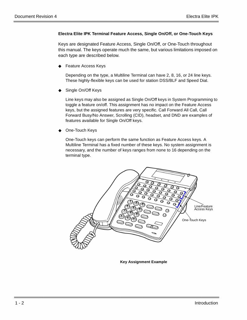
Electra Elite IPK Terminal Feature Access, Single On/Off, or One-Touch Keys
Keys are designated Feature Access, Single On/Off, or One-Touch throughout this manual. The keys operate much the same, but various limitations imposed on each type are described below.
Feature Access Keys
Depending on the type, a Multiline Terminal can have 2, 8, 16, or 24 line keys. These highly-flexible keys can be used for station DSS/BLF and Speed Dial.
Single On/Off Keys
Line keys may also be assigned as Single On/Off keys in System Programming to toggle a feature on/off. This assignment has no impact on the Feature Access keys, but the assigned features are very specific. Call Forward All Call, Call Forward Busy/No Answer, Scrolling (CID), headset, and DND are examples of features available for Single On/Off keys.
One-Touch Keys
One-Touch keys can perform the same function as Feature Access keys. A Multiline Terminal has a fixed number of these keys. No system assignment is necessary, and the number of keys ranges from none to 16 depending on the terminal type.
Key Assignment Example
One-Touch Keys
Line/Feature Access Keys

Electra Elite IPK Document Revision 4
Features and Specifications Manual 1 - 3
___________________________________________________________________________________
___________________________________________________________________________________
Dterm Series i Terminals
The Dterm Series i Terminals (DTR telephones) with or without LCD display offer a variety of colors and line sizes.
Terminals are available in black or white.
The large Liquid Crystal Display (LCD) on display terminals provides call status data and programming information.
Line sizes include 8-line, 16-line, and 32-line. 2-line on the DTR-2DT-1.
Speakerphone with full handsfree operation and headset jack is standard (except on the DTR-2DT-1).
All but the DTR-2DT-1, DTR-1-1, DTR-1HM-1 and Cordless terminals are compatible with the AD(A)-R, AP(A)-R, AP(R)-R , CT(A)-R and HF-R Unit adapters. The AP(R)-R Unit requires an AC(A)-R Unit to supply AC power. For Attendant Positions, an Attendant Add-On DCR-60-1 CONSOLE is available with 60 station and/or outside line assignments and 12 function keys. The DTR-2DT-1 has an internal Analog Port without ringer.
A two-line terminal with two Flexible Line keys (each with 2-color LED), nine function keys, built-in speakerphone, a large LED to indicate incoming calls or messages, and an outgoing only Analog SLT Port [AD(A)-R] is also available.
The Electra Elite IPK Single Line Terminals are offered in two variations (DTR-1-1 and DTR-1HM-1). Both terminals come in black or white. Both have DTMF and Pulse Dialing compatibility, and offer Flash and Redial key functionality. The Electra Elite IPK Single Line Terminals come standard with a Message Waiting Indicator that also functions as an Incoming Call Indication. During a call, the receive audio level can be increased three levels and decreased two levels from the default setting (six volume level settings in all). The terminals offer four ring volume settings (Off, Soft, Medium, and Loud), and three ring patterns (Slow, Medium, and Fast). The DTR Single Line Terminals also have a Data Port that functions similar to that of an AP(R)-R optional adapter, and have a built-in wall mount adapter. The DTR-1HM-1 terminal has eight programmable speed dial buttons (maximum 21 digits each). The DTR-1HM-1 also has Hold and Monitor Function keys.
1 - 4 Introduction
___________________________________________________________________________________
___________________________________________________________________________________Document Revision 4 Electra Elite IPK
Dterm IPK ITH Terminals
The Dterm IPK ITH Terminals come with LCD display and offer a variety of colors and line sizes:
Terminals are available in black or white.
The large Liquid Crystal Display (LCD) on display terminals provides call status data and programming information.
Line sizes include 8-line and 16-line.
Speakerphone with full-duplex handsfree operation and headset jack is standard.
Terminals are compatible with AD(A)-2R and PS(A)-R.
Electra Elite and Dterm Series E Terminals
The Electra Elite Terminals (DTU telephones) and Dterm Series E terminals (DTP telephones) with or without LCD displays are available in a variety of colors and lines sizes.
Terminals are available in black or white.
The large Liquid Crystal Display (LCD) on the display terminals provides call status data and programming information.
Line sizes include 8-line, 16-line, and 32-line.
Speakerphone with full handsfree operation and headset jack is standard.
The Dterm Handset Cordless terminal is a 16-button phone (display only).
An Attendant Add-On DCU-60-1 CONSOLE is available for 60 station and/or outside line assignments and 12 function keys.
An SLT Adapter can be used in place of a digital terminal for connecting Single Line Telephones, or similar devices.

Features and Specifications Manual 2 - 1
___________________________________________________________________________________
___________________________________________________________________________________
Features Chapter 2
SECTION 1 GENERAL INFORMATION
All features available with the Electra Elite IPK system are listed alphabetically by name and described in this document. The following information is provided, when applicable, for each feature:
Feature Description – briefly describes the feature and, when applicable, tells how the feature is used by the end-user.
System Availability – describes Multiline Terminals that can be used with this feature and lists any additional equipment, such as adapters or ETUs, that must be installed for this feature to operate.
Operating Procedures – contains detailed procedures for using each feature.
Quick Access Code Reference – provides a table for those features with associated Access Codes that are used with the operation of the feature. This table has Default, Access Code Name, and Alphabetic Designation columns.
Default – indicates the default values for the Access Codes that are set when a new system is installed). Access Codes, except for System and Fixed codes, can be changed in System Programming.
Access Code Name – indicates the name associated with the Access Code. The code type is shown in parentheses at the end of each code name. Access Code types include the following:
System Codes are usually 1-digit codes that apply to the operation of the system. These codes can be changed using Memory Block 1-1-46 [Access Code (1-Digit) Assignment].
Intercom Codes are 2-digit codes that apply to the associated feature and indicate Access Codes that can be changed using Memory Blocks 1-1-46 [Access Code (1-Digit) Assignment] and 1-1-47 [Access Code (2-Digit) Assignment].

2 - 2 Features
___________________________________________________________________________________
___________________________________________________________________________________Document Revision 4 Electra Elite IPK
Feature Codes are typically 3-digit codes and indicate Access Codes that apply to the associated feature. These codes can be changed using Memory Blocks 1-1-46 [Access Code (1-Digit) Assignment] and 1-1-48 [Access Code (3-Digit) Assignment].
Fixed Codes are set in the system and cannot be changed.
Alphabetic Designation – the alphabetic equivalent that helps you to easily remember the Access Code. These designations are available only for Feature and Intercom codes.
Service Conditions – specifies conditions that apply to the feature operation.
Related Features Lists – lists any associated features.
SECTION 2 OPERATING PROCEDURES
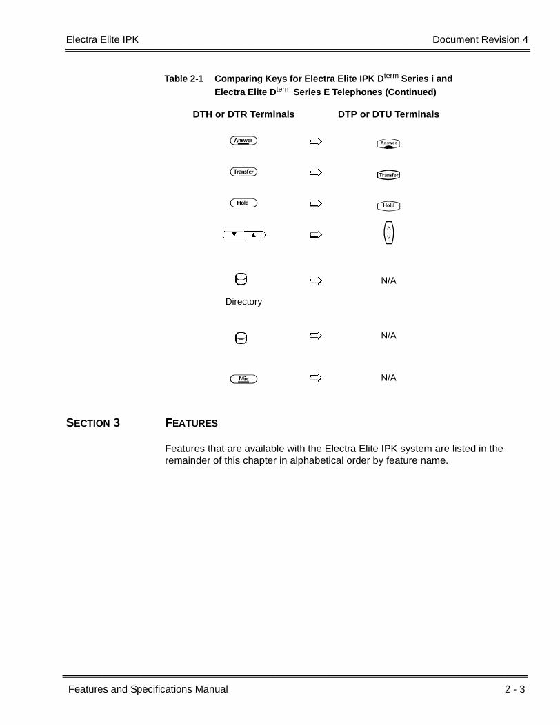
The operating procedures are the same for the Electra Elite IPK, Electra Elite, Dterm Series E, and Dterm Series i Multiline Terminals. The Series i (DTR) terminals have an added MIC key and two buttons: Directory and Message. Minor key differences are listed below. These differences are important when performing the operations listed in this manual.
Table 2-1 Comparing Keys for Electra Elite IPK Dterm Series i and Electra Elite Dterm Series E Telephones
DTH or DTR Terminals DTP or DTU Terminals
A T
B Q
A~K A~K
J J
L L
C S
D R
E P
Electra Elite IPK Document Revision 4
Features and Specifications Manual 2 - 3
___________________________________________________________________________________
___________________________________________________________________________________
SECTION 3 FEATURES
Features that are available with the Electra Elite IPK system are listed in the remainder of this chapter in alphabetical order by feature name.
F O
G N
H U
UV M
Directory
N/A
N/A
I N/A
Table 2-1 Comparing Keys for Electra Elite IPK Dterm Series i and Electra Elite Dterm Series E Telephones (Continued)
DTH or DTR Terminals DTP or DTU Terminals
2 - 4 Features
___________________________________________________________________________________
___________________________________________________________________________________Document Revision 4 Electra Elite IPK
THIS PAGE INTENTIONALLY LEFT BLANK

Features and Specifications Manual A - 1
___________________________________________________________________________________
___________________________________________________________________________________
Account Code Entry A-1
FEATURE DESCRIPTION
Account Code Entry allows assignment of Account Codes with up to 16 digits. Account Codes are incorporated in the call records generated by Station Message Detail Recording (SMDR) and provide a reference for billing.
SYSTEM AVAILABILITY
Terminal Type:
All Stations
Required Components:
MIFM-U( ) ETU
- OR -
SPE(M)-U10 ETU
OPERATING PROCEDURES
From a Multiline Terminal with an outside call in progress:
1. Press A .
2. Dial Access Code FF (fixed Access Code).
3. Enter the Account Code (Up to 16 digits) using the dial pad while talking with the outside party.
4. Press A .
- OR - (R4000 or higher)
Continue talking to outside party; after eight seconds fixed time-out, the Account Code is entered.
- OR - (R4000 or higher)
Hang up after entering Account Code; the call is terminated and the Account Code is entered.

A - 2 Account Code Entry
___________________________________________________________________________________
___________________________________________________________________________________Document Revision 4 Electra Elite IPK
From a Multiline Terminal with an outside call on hold:
1. While receiving internal dial tone, dial Account Code Entry Access Code XX (not assigned at default).
2. Enter the Account Code using the dial pad.
3. Retrieve the held call.
- OR -
While receiving internal dial tone, press the Feature Access or One-Touch key programmed for Account Code Entry.
4. Enter the Account Code using the dial pad.
5. Retrieve the held call.
From a Single Line Telephone with an outside call in progress:
1. Press the hookswitch, and wait for a new internal dial tone; the outside party is put on hold.
2. Dial Account Code Entry Access Code XX (no default assigned).
3. Enter the Account Code using the dial pad.
4. Use a hookflash to return to the held call.
QUICK ACCESS CODE REFERENCE
SERVICE CONDITIONS
General
The Interdigit timer for Account Code entry is fixed at eight seconds.
The Multiline Terminal user can enter an Account Code while talking with the outside party. Tones are not sent to the CO line, and the outside party is not put on hold.
Default Access Code NameAlphabetic
Designation
66 Feature Access Code (Fixed) N/A

Electra Elite IPK Document Revision 4
Features and Specifications Manual A - 3
___________________________________________________________________________________
___________________________________________________________________________________
If multiple Account Codes are entered during one call, the last entry is output from SMDR.
The Account Code can have up to 16 digits.
Use Memory Block 1-5-26 (SMDR Incoming/Outgoing Print Selection) to control generation of an SMDR Report on incoming calls. When an Account Code is entered during an outgoing call, a call report is generated regardless of system assignment.
Account Codes can be programmed to a Feature Access or One-Touch key on any Multiline Terminal.
Restrictions
An Account Code cannot be entered when a station is part of a conference supported by the system.
An Account Code cannot be entered if a hookflash results in a conference when a Single Line Telephone has a call on hold and another call is in progress.
During Account Code Entry, Call Alert Notification is not provided.
An Account Code Entry does not print with SMDR unless the account code is entered after the Call Start time elapses.
When 5-, 6-, or 7-digit station numbers are used, only the last four digits of the extension numbers are printed in the SMDR.
RELATED FEATURES LIST
Feature Number
Feature Name
A-2 Account Code – Forced/Verified/Unverified
S-17 Station Message Detail Recording (SMDR)

A - 4 Account Code Entry
___________________________________________________________________________________
___________________________________________________________________________________Document Revision 4 Electra Elite IPK
GUIDE TO FEATURE PROGRAMMING
Orderand
ShortcutSystem Data Name
Memory Block
Function
1-8-07Attendant
Page-Line Key
1-8-08StationPage-
Line Key
+BTS Class of Service (Station) Feature Selection 2 1-8-08 3-6
+BTT Station to Class of Service Feature Assignment
4-17
+BAAccess Code (1-, 2-, or 3-Digit) Assignment 1-1-46/47/
48041
+BS Card Interface Slot Assignment 7-1
+BS MIF (SMDR) Assignment 7-3-02
+BS MIF (LCR) Assignment 7-3-01
+AS Printer Connected Selection 1-5-13
+AS Printer Line Feed Control Selection 1-5-14
+AS SMDR Incoming/Outgoing Print Selection 1-5-26
+AS SMDR Valid Call Time Assignment 1-5-25
+AS SMDR Print Format 1-5-02
+AS SMDR Telephone Print Selection 4-56
+CSS Com Port Baud Rate Setting Assignment 1-8-35
+BM Start Time Selection 1-1-05
+AC Station to Timer Class of Service 4-71
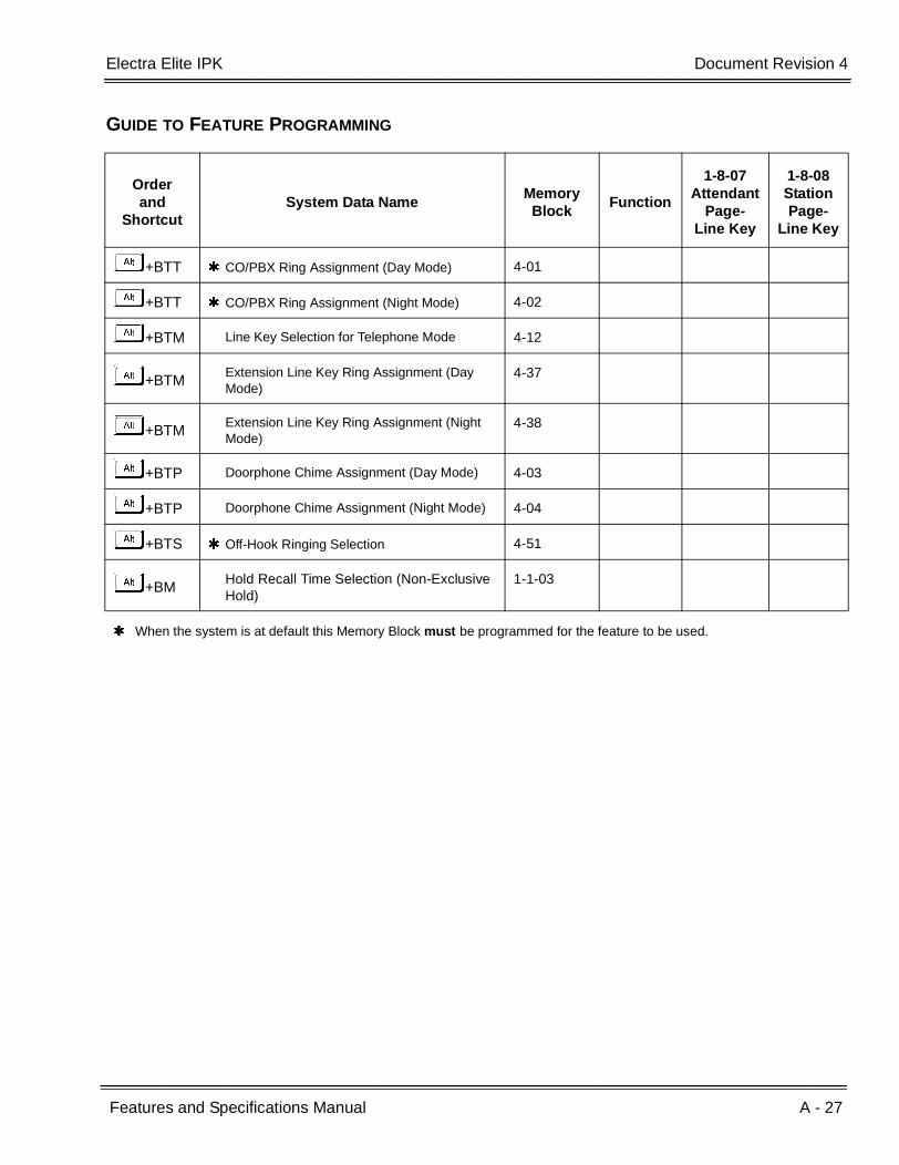
When the system is at default this Memory Block must be programmed for the feature to be used.

Features and Specifications Manual A - 5
___________________________________________________________________________________
___________________________________________________________________________________
Account Code – Forced/Verified/Unverified A-2
FEATURE DESCRIPTION
Account Code – Forced/Verified forces selected station users to dial an Access Code and a verified Account Code before making an outgoing call. The outgoing call is processed only after the dialed Account Code is verified.
Account Code – Forced/Unverified forces selected station users to dial an Access Code and an unverified Account Code before making an outgoing call. The outgoing call is processed only after the unverified Account Code is dialed.
This feature allows a system administrator to control unauthorized outgoing calls. The Forced/Verified/Unverified Account Code is part of the Station Message Detail Recording (SMDR) call record. A Forced/Verified Account Code has a maximum of 13 digits.
SYSTEM AVAILABILITY
Terminal Type:
All Stations
Required Components:
MIFM-U( ) ETU
- OR -
SPE(M)-U10 ETU
OPERATING PROCEDURE
To enter Account Code – Forced/Verified/Unverified from any station:
1. Lift the handset, and wait for internal dial tone.
2. Dial the Forced Account Access Code. A second dial tone is received.
3. Dial the Forced Account Code. Wait for Internal dial tone.
4. Dial the Trunk Access code and the outside number.

A - 6 Account Code – Forced/Verified/Unverified
___________________________________________________________________________________
___________________________________________________________________________________Document Revision 4 Electra Elite IPK
To program Account Code – Forced/Verified from Attendant Position:
1. Lift the handset, and wait for internal dial tone.
2. Dial the Forced Account Access Code (not assigned at default), and wait for a second dial tone.
3. Dial the Forced Account Number (KKA~ EKK).
4. Dial the Forced Account Code (default: 10 digits). Wait for Confirmation tone.
5. Press G to enter the information. The next Account Number is displayed. (Repeat steps 4 ~ 5 until all desired Account Codes are entered.)
6. Press E to stop entering Account Codes.
To use this feature with Scrolling Directories:
1. Press theV(SYS. or STA. softkey) to designate system or station speed dialing.
2. Press theV(UP or DOWN softkey) to view the names/numbers listed in the directory.
- OR -
Press a dial pad key (to select the first letter of the name or number of the desired speed dial buffer) and dialJ.
3. To dial the number press E or lift the handset.
4. Enter the Account Code.
SERVICE CONDITIONS
General:
Only outgoing calls from an intercom require a Forced Account Access Code. Direct access to trunks bypasses this feature.
Reorder tone is provided when an outgoing call is dialed without entering the Forced Account Access Code and a Forced Account Code.
Call Alert Notification is not provided during Account Code Entry verification and programming.
PBR Time values apply when a Single Line Telephone is used to enter a Forced Account Code.
Forced Account Codes can be uploaded, downloaded, or modified using PC based System Programming.

Electra Elite IPK Document Revision 4
Features and Specifications Manual A - 7
___________________________________________________________________________________
___________________________________________________________________________________
Forced Account Code Verified/Unverified and Account Code entries are printed on the SMDR report if both are used.
A is placed in front of the Forced Account Codes on the SMDR reports to distinguish them from other Account Code entries.
A total of 500 Forced/Verified Account Codes can be entered system-wide.
When the Interdigit time (default 10s) expires after the user inputs a Forced Account Code, Busy Tone is generated.
Restrictions:
Existing restrictions and Least Cost Routing (LCR) assignments are applied after Forced Account Codes are entered.
When a 911 call is placed, Account Code Forced/Verified is overridden by the following:
Emergency 911 Cut-Through is enabled.
A CAMA trunk is installed and enabled.
Enhanced 911 calls override the forced account code and are controlled by the Emergency 911 Dialing Route Assignment.
Verified and Unverified Forced Account Codes cannot be used in the same Class of Service.
When 5-, 6-, or 7-digit station numbers are used, only the last four digits of the extension numbers are printed in the SMDR.
RELATED FEATURES LIST
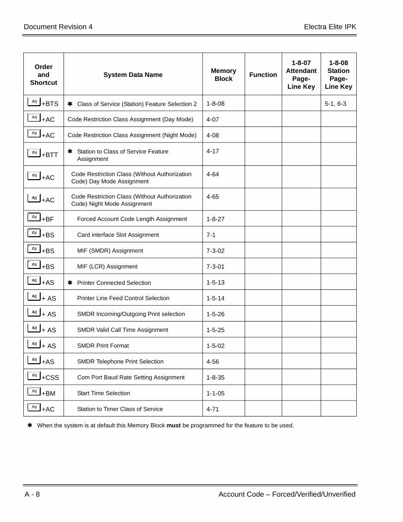
GUIDE TO FEATURE PROGRAMMING
Feature Number
Feature Name
A-1 Account Code Entry
A-16 Authorization Code
S-17 Station Message Detail Recording (SMDR)
Orderand
ShortcutSystem Data Name
Memory Block
Function
1-8-07Attendant
Page-Line Key
1-8-08StationPage-
Line Key
+BA Access Code (1-, 2-, or 3-Digit) Assignment 1-1-46~48 146,147
+BTS Class of Service (Attendant) Feature Selection 1
1-8-07 2-8
A - 8 Account Code – Forced/Verified/Unverified
___________________________________________________________________________________
___________________________________________________________________________________Document Revision 4 Electra Elite IPK
+BTS Class of Service (Station) Feature Selection 2 1-8-08 5-1, 6-3
+AC Code Restriction Class Assignment (Day Mode) 4-07
+AC Code Restriction Class Assignment (Night Mode) 4-08
+BTT Station to Class of Service Feature Assignment
4-17
+ACCode Restriction Class (Without Authorization Code) Day Mode Assignment
4-64
+ACCode Restriction Class (Without Authorization Code) Night Mode Assignment
4-65
+BF Forced Account Code Length Assignment 1-8-27
+BS Card interface Slot Assignment 7-1
+BS MIF (SMDR) Assignment 7-3-02
+BS MIF (LCR) Assignment 7-3-01
+AS Printer Connected Selection 1-5-13
+ AS Printer Line Feed Control Selection 1-5-14
+ AS SMDR Incoming/Outgoing Print selection 1-5-26
+ AS SMDR Valid Call Time Assignment 1-5-25
+ AS SMDR Print Format 1-5-02
+AS SMDR Telephone Print Selection 4-56
+CSS Com Port Baud Rate Setting Assignment 1-8-35
+BM Start Time Selection 1-1-05
+AC Station to Timer Class of Service 4-71
When the system is at default this Memory Block must be programmed for the feature to be used.
Orderand
ShortcutSystem Data Name
Memory Block
Function
1-8-07Attendant
Page-Line Key
1-8-08StationPage-
Line Key

Features and Specifications Manual A - 9
___________________________________________________________________________________
___________________________________________________________________________________
Add-On Conference A-3
FEATURE DESCRIPTION
Add-On Conference allows a conference call with a total of four parties with various combinations of outside lines and stations. This increases efficiency by allowing multiple parties to enter a conversation.
System Software supports up to 16, 4-party conferences with no more than two outside lines per conference.
ENHANCEMENT(S)
With Release R2000 or higher, a Single Line Telephone or PSII can perform a 1 terminal - 2 outside party conference call.
SYSTEM AVAILABILITY
Terminal Type:
All stations
Required Components:
None
OPERATING PROCEDURES
To initiate an Add-On Conference using a Multiline Terminal with a call in progress:
1. Press D .
2. Dial a station number or outside party, and inform the answering party of the conference.
3. Press D again. The D LED is on continuously. Talk with both parties.
4. Repeat steps 1~3 to add an additional party to the conference.

A - 10 Add-On Conference
___________________________________________________________________________________
___________________________________________________________________________________Document Revision 4 Electra Elite IPK
To initiate an Add-On Conference using a Single Line Telephone with a call in progress:
1. Press the hookswitch to place the first call on hold.
2. Dial an internal station and announce conference.
3. Press the hookswitch again. Talk with both parties.
4. Repeat steps 1~3 to add an additional party to the conference.
To initiate a 2 Outside Party Add-On Conference using a Single Line Telephone with an outside call in progress (R2000 or higher):
1. Provide hookflash. The call is placed on Exclusive Hold. Receive internal dial tone.
2. Dial the Trunk Access Code for desired trunk.
3. Dial the desired number and wait for the party to answer.
4. Provide hookflash again. Talk with both parties.
SERVICE CONDITIONS
General:
The elapsed time of the call from the originating terminal is shown on display Multiline Terminals.
When all conference circuits are in use, the red Conference key on each Multiline Terminal is on.
Allowed conference configurations are:
4 terminals - no outside party
3 terminals - 1 outside party
3 terminals - no outside party
2 terminals - 1 outside party
1 terminal - 2 outside parties
Only one member of a conference can place a conference on hold at a time.
When the conference is placed on hold, the Conference LED flashes on all phones in the conference.

Electra Elite IPK Document Revision 4
Features and Specifications Manual A - 11
___________________________________________________________________________________
___________________________________________________________________________________
Recall is not provided at the Multiline Terminal when a conference is on hold.
The CO to CO conference loss is 6 db (3 db per CO). This does not include the loss already occurring on each CO circuit. A telephone for conference connection incurs a 10 db loss.
Restrictions:
A Single Line Telephone cannot be used to originate a 2-party CO conference (R1700 or lower only).
When a Single Line Telephone or PSII is attempting to establish a 2-party outside conference call, the following apply for outside lines without answer supervision:
A hookflash to join the parties before Memory Block 1-3-11(SLT/PSII Talk Start timer) elapses results in dropping the new call and returns the user to the original call.
A hookflash to join the parties after Memory Block 1-3-11(SLT/PSII Talk Start timer) elapses results in a three party (two COs and one Single Line Telephone) conference call.
When a Single Line Telephone or PSII is attempting to establish a 2-party outside conference call, the following apply for outside lines with answer supervision:
A hookflash to join the parties before far end answer detection results in dropping the new call and returns the user to the original call.
A hookflash to join the parties after far end answer detection results in a three party (two COs and one Single Line Telephone) conference call.
A Single Line Telephone connected to the AP(A)-R/AP(R)-R Unit or APA-U/APR-U Unit does not support a 1 terminal - 2 outside parties conference call.
A Multiline Terminal user on hold cannot enter another conference.
When 5-, 6-, or 7-digit station numbers are used, only the last four digits of the extension numbers are displayed during an Add-On Conference call.
A Multiline Terminal cannot generate DTMF tones while engaged in a conference.
A - 12 Add-On Conference
___________________________________________________________________________________
___________________________________________________________________________________Document Revision 4 Electra Elite IPK
RELATED FEATURES LIST
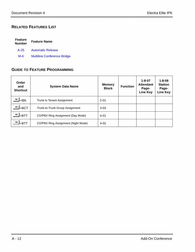
GUIDE TO FEATURE PROGRAMMING
Feature Number
Feature Name
A-25 Automatic Release
M-4 Multiline Conference Bridge
Orderand
ShortcutSystem Data Name
Memory Block
Function
1-8-07Attendant
Page-Line Key
1-8-08StationPage-
Line Key
+BN Trunk to Tenant Assignment 2-01
+BCT Trunk-to-Trunk Group Assignment 3-03
+BTT CO/PBX Ring Assignment (Day Mode) 4-01
+BTT CO/PBX Ring Assignment (Night Mode) 4-02

Features and Specifications Manual A - 13
___________________________________________________________________________________
___________________________________________________________________________________
All Call Page A-4
FEATURE DESCRIPTION
All Call Page allows simultaneous paging (internal and external) of all idle Multiline Terminals in a zone over each built-in speaker and over all external paging speakers. This enables a person within hearing distance of a Multiline Terminal or external speaker to respond to the paging call.
SYSTEM AVAILABILITY
Terminal Type:
All Multiline Terminals
Required Components:
None
OPERATING PROCEDURES
To originate a page on a Multiline Terminal:
1. Lift the handset, and wait for internal dial tone (or press H when the user is engaged on a call).
2. Dial Access Code EI (set as default) for All Call Page.
3. Page.
To answer a page on a Multiline Terminal:
1. Go off-hook.
2. Wait for internal dial tone.

A - 14 All Call Page
___________________________________________________________________________________
___________________________________________________________________________________Document Revision 4 Electra Elite IPK
3. Dial Meet-Me Access Code EJ (set as default); the display changes to show the originator station number.
4. Talk with All Call Page originator.
To originate a page on a Single Line Telephone:
1. Lift the handset, and wait for internal dial tone or press the hookswitch when the user is engaged in a call.
2. Dial All Call Page Access Code EI (default).
3. Page.
To answer a page on a Single Line Telephone:
1. Lift the handset or press the hookswitch when the user is engaged in a call.
2. Wait for dial tone.
3. Dial Meet-Me Access Code EJ (default).
4. Talk with All Call Page originator.
QUICK ACCESS CODE REFERENCE
Default Access Code NameAlphabetic
Designation
59 All Internal/External Zone Paging N/A
5 Internal/External Meet-Me N/A

Electra Elite IPK Document Revision 4
Features and Specifications Manual A - 15
___________________________________________________________________________________
___________________________________________________________________________________
SERVICE CONDITIONS
General:
All Call Page can be originated or answered by Meet-Me Answer from internal dial tone.
All Call Page times out using the External Paging Time Out (default is five minutes).
An outside line can be conferenced with External Page to allow a conversation to be monitored.
The default Access Code for All Call Page is 59. The default Access Code for All Call Page Meet-Me code is 5 (Internal/External Meet-Me).
Use Memory Block 4-31 (Receiving Internal/All Call Page Selection) to allow or deny a station from receiving paging. This includes All Call Page, Internal Zone Paging, and External Zone Paging. Internal Emergency All Call Page is not included.
Restrictions:
A Multiline Terminal user engaged in a handsfree call cannot receive All Call Page or Internal Zone Pages.
Only one All Call Page or Internal Zone Page can be established at a time. Another page can be originated as soon as the first is abandoned or answered by Meet-Me Answer.
Simultaneous zone paging (Internal Zones A, B, and C) can be established at one time; however, All Internal Zone Paging and Internal Emergency All Call Page cannot be performed when any other internal page is in use.
If there are no idle stations available to receive an All Call Page, the All Call Page is denied, and BUSY is displayed at the station attempting to originate the page.
RELATED FEATURES LIST
Feature Number
Feature Name
E-17 External Zone Paging (Meet-Me)
I-6 Internal Zone Paging (Meet-Me)

A - 16 All Call Page
___________________________________________________________________________________
___________________________________________________________________________________Document Revision 4 Electra Elite IPK
GUIDE TO FEATURE PROGRAMMING
Orderand
ShortcutSystem Data Name
Memory Block
Function
1-8-07Attendant
Page-Line Key
1-8-08StationPage-
Line Key
+BAAccess Code (1-, 2-, or 3-Digit) Assignment 1-1-46/47/
48070~079,081
+BTM Internal Zone Paging Selection 4-93
+BTT Receiving Internal/All Call Page Selection 4-31
+BP Internal Paging Alert Tone Selection 1-2-25
+BP Internal Paging Timeout Selection 1-2-00
+BP External Speaker Connection Selection 1-7-02
+BP External Paging Alert Tone Selection 1-7-03
+BP External Speaker Pre-Tone/Chime Selection 1-7-08
+BP External Speaker Chime Start time Selection 1-7-09
+BP External Paging Timeout Selection 1-7-06

Features and Specifications Manual A - 17
___________________________________________________________________________________
___________________________________________________________________________________
Alphanumeric Display A-5
FEATURE DESCRIPTION
Each Electra Elite, Dterm Series E, Electra Elite IPK, or Dterm Series i Display Multiline Terminal has a 24-character by 3-line Liquid Crystal Display (LCD). These displays provide information such as: date/time, elapsed call time on outside calls, digits dialed, internal calling party number, Customized Message, Speed Dial entries or softkeys.
SYSTEM AVAILABILITY
Terminal Type:
All Display Multiline Terminals
Required Components:
LCD DISPLAYS
Refer to Display Indications table below.
Display Location Definition
12:24 AM WED 10 All Stations with LCD
Clock/Calendar
ALL 100 - - > [ ] Set Call Forward – All Call
ALL FWD CANCLD Cancel DND/Call Forward – All Call System-Wide
FWD/DND CANCLD Originator Cancel DND/Call Forward – All Call At Individual Stations
FWD SET [ ] Originator Set Call Forward – All Call From Forward To Extension
FWD RESET [ ] Reset Call Forward – All Call From Forward To Extension
BUSY 100 -- > [ _ ] Set Call Forward – Busy
FWD BUSY CANCLD Cancel Call Forward – Busy
NOANS 100 - > [ ] Set Call Forward – No Answer
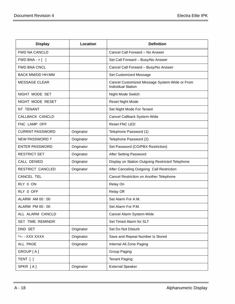
A - 18 Alphanumeric Display
___________________________________________________________________________________
___________________________________________________________________________________Document Revision 4 Electra Elite IPK
FWD NA CANCLD Cancel Call Forward – No Answer
FWD BNA - > [ ] Set Call Forward – Busy/No Answer
FWD BNA CNCL Cancel Call Forward – Busy/No Answer
BACK MM/DD HH:MM Set Customized Message
MESSAGE CLEAR Cancel Customized Message System-Wide or From Individual Station
NIGHT MODE SET Night Mode Switch
NIGHT MODE RESET Reset Night Mode
NT TENANT Set Night Mode For Tenant
CALLBACK CANCLD Cancel Callback System-Wide
FNC LAMP OFF Reset FNC LED
CURRNT PASSWORD Originator Telephone Password (1)
NEW PASSWORD ? Originator Telephone Password (2)
ENTER PASSWORD Originator Set Password (CO/PBX Restriction)
RESTRICT SET Originator After Setting Password
CALL DENIED Originator Display on Station Outgoing Restricted Telephone
RESTRICT CANCLED Originator After Canceling Outgoing Call Restriction
CANCEL TEL Cancel Restriction on Another Telephone
RLY 0 ON Relay On
RLY 0 OFF Relay Off
ALARM AM 00 : 00 Set Alarm For A.M.
ALARM PM 00 : 00 Set Alarm For P.M.
ALL ALARM CANCLD Cancel Alarm System-Wide
SET TIME REMINDR Set Timed Alarm for SLT
DND SET Originator Set Do Not Disturb
*<- - XXX XXXX Originator Save and Repeat Number Is Stored
ALL PAGE Originator Internal All Zone Paging
GROUP [ A ] Group Paging
TENT [ ] Tenant Paging
SPKR [ A ] Originator External Speaker
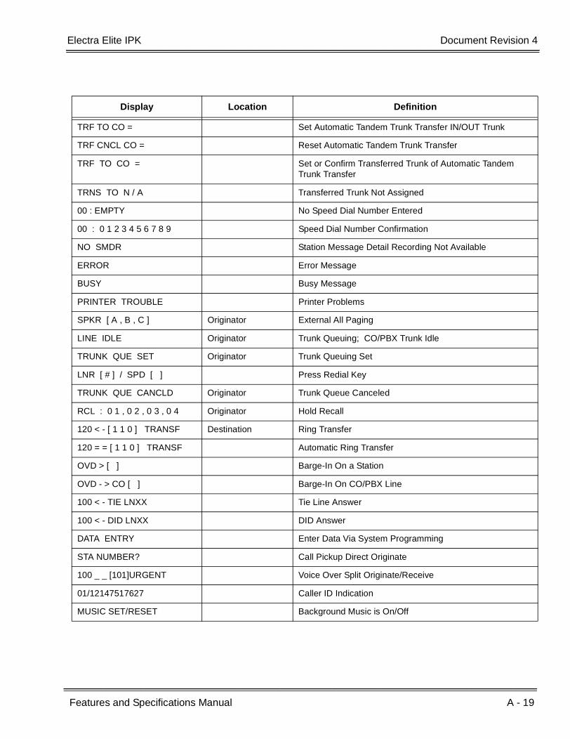
Display Location Definition
Electra Elite IPK Document Revision 4
Features and Specifications Manual A - 19
___________________________________________________________________________________
___________________________________________________________________________________
TRF TO CO = Set Automatic Tandem Trunk Transfer IN/OUT Trunk
TRF CNCL CO = Reset Automatic Tandem Trunk Transfer
TRF TO CO = Set or Confirm Transferred Trunk of Automatic Tandem Trunk Transfer
TRNS TO N / A Transferred Trunk Not Assigned
00 : EMPTY No Speed Dial Number Entered
00 : 0 1 2 3 4 5 6 7 8 9 Speed Dial Number Confirmation
NO SMDR Station Message Detail Recording Not Available
ERROR Error Message
BUSY Busy Message
PRINTER TROUBLE Printer Problems
SPKR [ A , B , C ] Originator External All Paging
LINE IDLE Originator Trunk Queuing; CO/PBX Trunk Idle
TRUNK QUE SET Originator Trunk Queuing Set
LNR [ # ] / SPD [ ] Press Redial Key
TRUNK QUE CANCLD Originator Trunk Queue Canceled
RCL : 0 1 , 0 2 , 0 3 , 0 4 Originator Hold Recall
120 < - [ 1 1 0 ] TRANSF Destination Ring Transfer
120 = = [ 1 1 0 ] TRANSF Automatic Ring Transfer
OVD > [ ] Barge-In On a Station
OVD - > CO [ ] Barge-In On CO/PBX Line
100 < - TIE LNXX Tie Line Answer
100 < - DID LNXX DID Answer
DATA ENTRY Enter Data Via System Programming
STA NUMBER? Call Pickup Direct Originate
100 _ _ [101]URGENT Voice Over Split Originate/Receive
01/12147517627 Caller ID Indication
MUSIC SET/RESET Background Music is On/Off
Display Location Definition

A - 20 Alphanumeric Display
___________________________________________________________________________________
___________________________________________________________________________________Document Revision 4 Electra Elite IPK
SERVICE CONDITIONS
French, Japanese, and Spanish characters are also available.
GUIDE TO FEATURE PROGRAMMING
Orderand
ShortcutSystem Data Name
Memory Block
Function
1-8-07Attendant
Page-Line Key
1-8-08StationPage-
Line Key
+BCT Trunk Name/Number Assignment 3-00
+BTT Station Name Assignment 4-18
+BE Speed Dial Number/Name Display Selection 1-1-33
+BI Customized Message 1~10 Assignment 1-2-09~18
+BTM Multilingual LCD Indication Selection 4-28
When the system is at default this Memory Block must be programmed for the feature to be used.
Features and Specifications Manual A - 21
___________________________________________________________________________________
___________________________________________________________________________________
Analog Line Extender (Dterm ® Analog EXT) A-6
FEATURE DESCRIPTION
The Dterm Analog EXT allows a user with an NEC Multiline Telephone to make or receive calls from a remote location while maintaining a station appearance from the office KTS.
SYSTEM AVAILABILITY
Terminal Type:
DTP-32DE-1 TEL
Required Components:
Electra Elite KTS with one ESI port
Dterm Analog extender (OF) with termination to an ESI port of the KTS and an analog line from the CO
Dterm Analog extender (RE) with termination to an analog line from the CO
DTP-32DE-1 Dterm Series E terminal
OPERATING PROCEDURES
Normal incoming call handling procedures apply.
SERVICE CONDITIONS
General:
Refer to Dterm Analog EXT Owners Manual for more information.
Use Memory Block 4-01 [CO/PBX Ring Assignment (Day Mode)] 0r 4-02 [CO/PBX Ring Assignment (Night Mode)] to assign incoming CO/PBX calls to ring on Multiline Terminals.
Use Memory Block 4-31 (Receiving Internal/All Call Page Selection) to disable (press LK 2) paging for the station.

A - 22 Analog Line Extender (Dterm ® Analog EXT)
___________________________________________________________________________________
___________________________________________________________________________________Document Revision 4 Electra Elite IPK
Restrictions:
The user must use a line that is not connected to the Dterm Analog EXT to make 911 calls. If a call is made from the remote terminal, the telephone number at the KTS location is sent to the emergency center.
Zone and voice paging must be turned off using KTS programming. The remote telephone should be programmed to ring for all incoming calls.
When the remote Multiline Terminal is programmed to answer multiple calls, they should ring at the terminal. Contact your authorized NEC dealer when system changes are required.
Synchronous ringing does not operate on the remote telephone. Incoming trunk calls automatically ring 2 sec. on/2 sec. off.
Analog fax machines and modems cannot operate with a DTP-32DE-1 Multiline Terminal that is connected to an APR-U Unit optional adapter.
Dterm Cordless terminals cannot be used with a DTP-32DE-1 Multiline Terminal or Dterm Analog EXT.
CTA-U Unit and CTU(S)-U Unit cannot be installed to a KTS remote Multiline Terminal to provide TAPI functionality with the KTS.
CTU(C)-U Unit (Coreline) cannot be used with a DTP-32DE-1 Multiline Terminal or Dterm Analog EXT.
Dterm PC and PCII do not function with Dterm Analog EXT.
The HFU-U/HF-R Unit handsfree adapter cannot operate with a DTP-32DE-1 Multiline Terminal or Dterm Analog EXT used in a home environment because of FCC restrictions, but it can operate in an office environment.
When 5-, 6-, or 7-digit station numbers are used, this feature is not available.
Features and Specifications Manual A - 23
___________________________________________________________________________________
___________________________________________________________________________________
Ancillary Device Connection A-7
FEATURE DESCRIPTION
Ancillary Device Connection allows installation of selected peripheral (ancillary) devices to a Multiline Terminal. This feature enhances peripheral device objectives.
An Electra Elite IPK Terminal user can accomplish this by using the AP(R)-R Unit (Analog Port Adapter with Ringer) or AP(A)-A Unit (Analog Port Adapter without Ringer) for analog telephone devices, or installing the AD(A)-R Unit to connect devices such as tape recorders.
The AP(A)-R/AP(R)-R Unit is the interface for installing a Single Line Telephone, Modem, Credit Card Reader, Wireless Headset, NEC Voicepoint/Voicepoint Plus Conferencing unit or other compatible analog device.
SYSTEM AVAILABILITY
Terminal Type:
DTH-8-1, DTH-8D-1, DTH-16D-1, DTH-32D-1, DTH 16LD-1
Required Components:
AD(A)-R, AP(A)-R, AP(R)-R
OPERATING PROCEDURES
Depends on the connected ancillary device.
SERVICE CONDITIONS
General:
The optional device fits underneath the terminal.
Engineering Technical Information Bulletins (ETIs) provide connection instructions for the various ancillary devices. Ancillary devices that are not covered by an ETI may not be compatible with Electra Elite Multiline Terminals. Verify with NEC Unified Solutions, Inc., National Technical Assistance Center (NTAC) before attempting hookup.
A - 24 Ancillary Device Connection
___________________________________________________________________________________
___________________________________________________________________________________Document Revision 4 Electra Elite IPK
Individual device conditions and operating procedures are provided in the applicable ETI Bulletins and ancillary device manufacturer information.
Restrictions:
A Single Line Telephone connected to an APR-U/AP(R)-R Unit or APA-U/AP(A)-R Unit cannot perform Trunk-to-Trunk Transfer and does not support a 1 terminal - 2 outside parties conference call.
A Single Line Telephone connected to an APR-U/AP(R)-R Unit or APA-U/AP(A)-R Unit does not support Message Waiting Indication.
RELATED FEATURES LIST
GUIDE TO FEATURE PROGRAMMING
Feature Number
Feature Name
E-2 Electra Elite IPK Terminals
E-3 Electra Elite Terminal Migration
E-4 Electra Professional Terminal Migration
F-7 Full Duplex Handsfree
F-8 Full Handsfree Operation
S-7 Single Line Telephone Access
Orderand
ShortcutSystem Data Name
Memory Block
Function
1-8-07Attendant
Page-Line Key
1-8-08StationPage-
Line Key
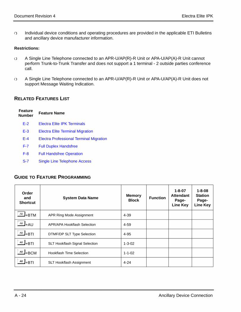
+BTM APR Ring Mode Assignment 4-39
+AU APR/APA Hookflash Selection 4-59
+BTI DTMF/DP SLT Type Selection 4-95
+BTI SLT Hookflash Signal Selection 1-3-02
+BCM Hookflash Time Selection 1-1-02
+BTI SLT Hookflash Assignment 4-24

Features and Specifications Manual A - 25
___________________________________________________________________________________
___________________________________________________________________________________
Answer Hold A-8
FEATURE DESCRIPTION
Answer Hold allows a Multiline Terminal user to press the flashing Answer key to answer an incoming ringing call. When the Multiline Terminal user is already answering a call, the first call is automatically placed on Non-Exclusive Hold when the second call is answered. Answer Hold is particularly useful at Attendant Positions or other central answering positions. Using the Answer key speeds call handling, and Answer Hold prevents accidental call dropping.
SYSTEM AVAILABILITY
Terminal Type:
All Multiline Terminals
Required Components:
None
OPERATING PROCEDURES
To answer calls on a different line key with a call in progress:
1. Receive CO/PBX incoming ring. The F LED flashes.
2. Press F , and answer the new call ( F LED goes off). The original call is put on Hold.
a. When the original call is on a Call Appearance Key, the call is placed on Non-Exclusive Hold on the Call Appearance Key.
b. When the call is on a line key, the call is placed on Non-Exclusive Hold on the line key.
3. Talk with the CO/PBX incoming caller.
4. When additional calls are received, press F to place the current call on Hold and connect to the next call. (Refer to a. and b. above.)
A - 26 Answer Hold
___________________________________________________________________________________
___________________________________________________________________________________Document Revision 4 Electra Elite IPK
SERVICE CONDITIONS
General:
CO/PBX ringing transfer/camp-on calls may be answered.
When multiple incoming calls activate the Answer key LED, the LED continues to flash until all calls are answered.
Use Memory Block 4-51 (Off-Hook Ringing Selection) to assign YS (default) or NO for Off-hook ringing for Answer Hold to work.
Restrictions:
Answer Hold does not function for incoming internal calls.
CO/PBX incoming calls not assigned to ring or assigned to other tenants do not activate Answer Hold.
DID/Tie line and DIT/ANA calls do not activate Answer Hold.
When all Call Appearance keys are in use, the next call cannot be answered.
Electra Elite IPK Document Revision 4
Features and Specifications Manual A - 27
___________________________________________________________________________________
___________________________________________________________________________________
GUIDE TO FEATURE PROGRAMMING
Orderand
ShortcutSystem Data Name
Memory Block
Function
1-8-07Attendant
Page-Line Key
1-8-08StationPage-
Line Key
+BTT CO/PBX Ring Assignment (Day Mode) 4-01
+BTT CO/PBX Ring Assignment (Night Mode) 4-02
+BTM Line Key Selection for Telephone Mode 4-12
+BTMExtension Line Key Ring Assignment (Day Mode)
4-37
+BTMExtension Line Key Ring Assignment (Night Mode)
4-38
+BTP Doorphone Chime Assignment (Day Mode) 4-03
+BTP Doorphone Chime Assignment (Night Mode) 4-04
+BTS Off-Hook Ringing Selection 4-51
+BMHold Recall Time Selection (Non-Exclusive Hold)
1-1-03
When the system is at default this Memory Block must be programmed for the feature to be used.

A - 28 Answer Hold
___________________________________________________________________________________
___________________________________________________________________________________Document Revision 4 Electra Elite IPK
THIS PAGE INTENTIONALLY LEFT BLANK

Features and Specifications Manual A - 29
___________________________________________________________________________________
___________________________________________________________________________________
Answer Key A-9
FEATURE DESCRIPTION
Multiline Terminals have an Answer key with an LED that flashes when the Multiline Terminal user receives an incoming CO/PBX, Tie/DID transfer, or CO/PBX transfer call ringing in the same tenant group. When multiple calls are received, the Answer key is used to pick up calls. The Answer key continues flashing until the last unanswered call is answered. Press the Answer key during a call to hold the current call and allow the next call to be answered.
SYSTEM AVAILABILITY
Terminal Type:
All Multiline Terminals
Required Components:
None
OPERATING PROCEDURES
To answer calls using the Answer key:
1. Receive CO/PBX incoming ring. The F LED flashes.
2. Press F . The F LED goes out.
3. Talk with the CO/PBX incoming calling party.
4. When additional CO incoming calls are received, the F LED flashes again. Press F to place the current call on Non-Exclusive Hold and connect the Multiline Terminal user to the next call.
a. An original call on a Call Appearance Key is placed on Non-Exclusive Hold on the Call Appearance Key.
b. An original call on a line key is placed on Non-Exclusive Hold on the line key.
A - 30 Answer Key
___________________________________________________________________________________
___________________________________________________________________________________Document Revision 4 Electra Elite IPK
SERVICE CONDITIONS
General:
The Answer key LED functions for incoming CO/PBX calls, CO/PBX transfer/camp-on calls, and transfer/camp-on Tie/DID calls.
Incoming CO/PBX ringing calls to other tenants with the CO/PBX line appearance and ring assignment activate the Answer key LED.
Incoming calls answered by the Answer key are handled first in-first out.
Restrictions:
An Internal call, internal transfer/camp-on call, Secondary Incoming Extension, Automated Attendant, or Tie/DID call does not activate the Answer key LED.
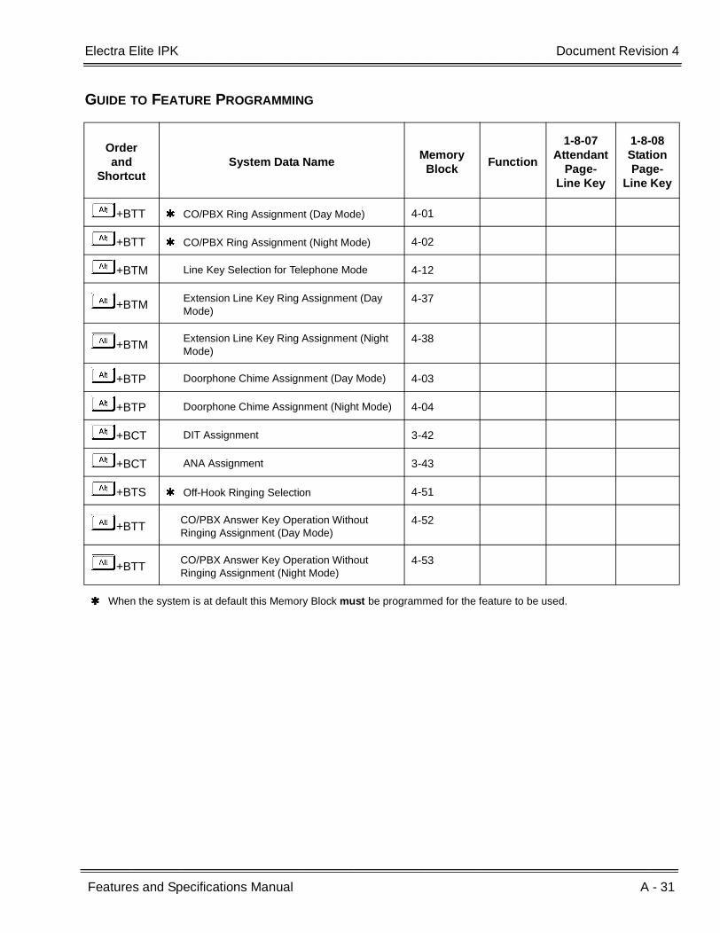
Electra Elite IPK Document Revision 4
Features and Specifications Manual A - 31
___________________________________________________________________________________
___________________________________________________________________________________
GUIDE TO FEATURE PROGRAMMING
Orderand
ShortcutSystem Data Name
Memory Block
Function
1-8-07Attendant
Page-Line Key
1-8-08StationPage-
Line Key
+BTT CO/PBX Ring Assignment (Day Mode) 4-01
+BTT CO/PBX Ring Assignment (Night Mode) 4-02
+BTM Line Key Selection for Telephone Mode 4-12
+BTMExtension Line Key Ring Assignment (Day Mode)
4-37
+BTMExtension Line Key Ring Assignment (Night Mode)
4-38
+BTP Doorphone Chime Assignment (Day Mode) 4-03
+BTP Doorphone Chime Assignment (Night Mode) 4-04
+BCT DIT Assignment 3-42
+BCT ANA Assignment 3-43
+BTS Off-Hook Ringing Selection 4-51
+BTTCO/PBX Answer Key Operation Without Ringing Assignment (Day Mode)
4-52
+BTTCO/PBX Answer Key Operation Without Ringing Assignment (Night Mode)
4-53
When the system is at default this Memory Block must be programmed for the feature to be used.

A - 32 Answer Key
___________________________________________________________________________________
___________________________________________________________________________________Document Revision 4 Electra Elite IPK
THIS PAGE INTENTIONALLY LEFT BLANK
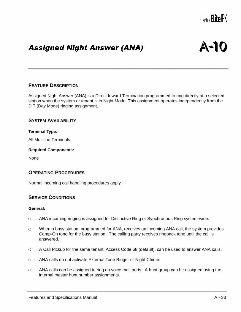
Features and Specifications Manual A - 33
___________________________________________________________________________________
___________________________________________________________________________________
Assigned Night Answer (ANA) A-10
FEATURE DESCRIPTION
Assigned Night Answer (ANA) is a Direct Inward Termination programmed to ring directly at a selected station when the system or tenant is in Night Mode. This assignment operates independently from the DIT (Day Mode) ringing assignment.
SYSTEM AVAILABILITY
Terminal Type:
All Multiline Terminals
Required Components:
None
OPERATING PROCEDURES
Normal incoming call handling procedures apply.
SERVICE CONDITIONS
General:
ANA incoming ringing is assigned for Distinctive Ring or Synchronous Ring system-wide.
When a busy station, programmed for ANA, receives an incoming ANA call, the system provides Camp-On tone for the busy station. The calling party receives ringback tone until the call is answered.
A Call Pickup for the same tenant, Access Code 68 (default), can be used to answer ANA calls.
ANA calls do not activate External Tone Ringer or Night Chime.
ANA calls can be assigned to ring on voice mail ports. A hunt group can be assigned using the internal master hunt number assignments.

A - 34 Assigned Night Answer (ANA)
___________________________________________________________________________________
___________________________________________________________________________________Document Revision 4 Electra Elite IPK
When a station, programmed for ANA, receives an incoming ANA call, internal ring tone is heard at all stations where a secondary incoming extension appears and is assigned to ring.
Incoming ANA calls cannot be answered directly at the CO line key appearance. The CO line key indicates Other Use (red LED).
While an incoming ANA call is being received, an internal call cannot be made.
Multiple CO/PBX lines can be assigned to ring at the same station, hunt group master number, or ACD/UCD Pilot number.
Incoming ANA calls follow the station Call Forward setting.
Restrictions:
When a CO/PBX line is assigned for ANA, the Night Mode CO/PBX ring assignment is disabled.
RELATED FEATURES LIST
GUIDE TO FEATURE PROGRAMMING
Feature Number
Feature Name
D-11 Direct Inward Termination (DIT)
Orderand
ShortcutSystem Data Name
Memory Block
Function
1-8-07Attendant
Page-Line Key
1-8-08StationPage-
Line Key
+BCT DIT Assignment 3-42
+BCT ANA Assignment 3-43
+BCT DIT/ANA Delay Answer Time Selection 3-61
+BCT DIT Tenant Assignment 3-62
+BCT DIT Weekend Mode Selection 3-63
+BCT DIT Night Mode Delay Answer Selection 3-64
+BN Trunk to Tenant Assignment 2-01
+BTT Telephone to Tenant Assignment 4-09

Electra Elite IPK Document Revision 4
Features and Specifications Manual A - 35
___________________________________________________________________________________
___________________________________________________________________________________
+BN Line Key Selection for Tenant Mode 2-06
+BTM Line Key Selection for Telephone Mode 4-12
+BTTCall Forward - Busy Immediately/Delay Selection
4-42
+BM Call Forward - No Answer Time Selection 1-2-22
When the system is at default this Memory Block must be programmed for the feature to be used.
Orderand
ShortcutSystem Data Name
Memory Block
Function
1-8-07Attendant
Page-Line Key
1-8-08StationPage-
Line Key
A - 36 Assigned Night Answer (ANA)
___________________________________________________________________________________
___________________________________________________________________________________Document Revision 4 Electra Elite IPK
THIS PAGE INTENTIONALLY LEFT BLANK
Features and Specifications Manual A - 37
___________________________________________________________________________________
___________________________________________________________________________________
Attendant Add-On Console A-11
FEATURE DESCRIPTION
The Attendant Add-On Console functions with a Multiline Terminal programmed as an Attendant. This console provides access to a maximum of 48 stations and/or outside lines. The Busy Lamp Field status is shown by a red LED for each station or trunk. Trunks can include CO/PBX, ISDN, DID, E&M Tie Lines, and FT1 lines. The Attendant Add-On Console also has 12 function keys that can be used for attendant messaging, paging access, or undefined functions.
SYSTEM AVAILABILITY
Terminal Type:
Any Multiline Terminal programmed as an Attendant Position
Required Components:
DCR-60-1/DCU-60-1 Console
OPERATING PROCEDURES
To transfer a call:
1. Attendant answers an incoming CO/PBX call.
2. Press the DSS/BLF key for the desired station. The calling party is put on Non-Exclusive Hold.
3. When the called party answers the Attendant call, the Attendant announces the call and then presses G on the Attendant Add-On Console.
4. Go on-hook.
- OR -
1. Attendant answers an incoming CO/PBX call.
2. Press the Attendant Add-On Console key for the desired station. The calling party is put on Non-Exclusive Hold.
A - 38 Attendant Add-On Console
___________________________________________________________________________________
___________________________________________________________________________________Document Revision 4 Electra Elite IPK
3. Press G on the Add-On Console.
4. Go on-hook.
To call a station:
1. Lift the handset, and wait for internal dial tone.
2. Press the DSS/BLF key for the desired station. Hear ringback tone or voice announce the station.
3. Called party answers.
To set/cancel Message Waiting or Station Outgoing Lockout (Outgoing Restrict) to station:
1. Press the Message Wait or Station Lockout key.
2. Press the DSS/BLF key for the desired station.
To make an outgoing call using the Attendant Add-On Console from the Attendant Position:
1. Go off-hook with the handset or press a CO line key on the Attendant Add-On Console.
2. Dial the desired number.
To answer an incoming call at the Attendant Add-On Console from the Attendant Position:
Press the incoming CO line key or flashing F if ringing is assigned.

Electra Elite IPK Document Revision 4
Features and Specifications Manual A - 39
___________________________________________________________________________________
___________________________________________________________________________________
SERVICE CONDITIONS
General:
The 48 DSS keys and 12 function keys on Attendant Add-On Consoles are flexible and can be changed.
Both DSS/BLF for stations and CO lines can appear on the same DCU-60-1/DCR-60-1 Console.
When the Attendant transfers a call, the transferred outside line remains on Non-Exclusive Hold until the call is answered.
Each installed Attendant Add-On Console is included in the maximum number of stations.
The keys are assigned at default as follows:
Busy Lamp Field indications show when a Multiline Terminal, outside line, or zone paging is in use.
Busy Lamp Field status indications at the Attendant Add-On Console are:
01~48 ICM Call 00~147(Depending On System Configuration)
49 Night Mode
50~53 Direct Paging Access Internal Zone and All Zone Page
54 Vacant
55 Message
56~59 External All Zone Paging External Zone and All Zone Page
60 Transfer
LED Indications: Busy Lamp Field Status:
Off Station Idle
Red Busy
Fast-flashing Red Do Not Disturb (DND)
Slow-flashing Red VM Message Waiting Indication

A - 40 Attendant Add-On Console
___________________________________________________________________________________
___________________________________________________________________________________Document Revision 4 Electra Elite IPK
Message Waiting/Station Outgoing Lockout status indications at the Attendant Add-On Console are:
Using an Attendant Add-On Console, the Attendant can set a message to a Single Line Telephone equipped with a Message Waiting LED and connected to an SLI(8)-U( ) ETU.
When the Message Waiting indication is set, the Large LED flashes green on Multiline Terminals and continues to flash until the message is answered or canceled by an Attendant.
Attendant Add-On Consoles can be assigned to any Multiline Terminal programmed as an Attendant Position.
When the entire system is switched into Night Mode, the Night Transfer (NT) key LED on the Attendant Add-On Console lights red.
An Attendant Add-On Console cannot have a Message Wait key and a Station Lockout key assigned at the same time.
Multiple CO calls ringing at an Attendant Station or Attendant Add-On Console are answered in first in-first out order.
Voice Mail MSG Waiting has priority over any other state of the flashing line key or One-Touch key.
LED Indications: Outside Line Status:
Off Outside Line Idle
Green In Use (by Attendant station)
Red Busy
Winking Call On Hold
Flashing Incoming Call
LED Indications: Station Status:
Off No Message/Lockout Not Set
Green Message Waiting/Lockout Set

Electra Elite IPK Document Revision 4
Features and Specifications Manual A - 41
___________________________________________________________________________________
___________________________________________________________________________________
The following Digital Voice Mail integrated functions can be assigned to keys on the Attendant Add-On Console:
Record Start
Record Pause/Restart
Record Erase
Record Finish
Record Erase/Restart
Urgent Page (Pager) ON/OFF
Record Confirmation
Restrictions:
Only four DCU-60-1/DCR-60-1 Consoles can be installed per system.
Only four Attendant Add-On Consoles can be connected to one station.
When tone signaling is selected in Memory Block 1-6-03 (DSS Call Voice/Tone Signal Selection), the called party cannot answer handsfree unless the DSS station dials 1 to switch to voice.
When 5-, 6-, or 7-digit station numbers are used, the Digital Voice Mail integrated functions (e.g., Record start) are not supported.
Incoming CAR keys are not supported.
RELATED FEATURES LIST
Feature Number
Feature Name
A-13 Attendant Positions
A-14 Attendant Station Outgoing Lockout
B-6 Busy Lamp Field on Multiline Terminals
M-2 Message Waiting

A - 42 Attendant Add-On Console
___________________________________________________________________________________
___________________________________________________________________________________Document Revision 4 Electra Elite IPK
GUIDE TO FEATURE PROGRAMMING
Orderand
ShortcutSystem Data Name
Memory Block
Function
1-8-07Attendant
Page-Line Key
1-8-08StationPage-
Line Key
+BS Telephone Type Assignment 7-2
+BTD Attendant Add-On Console to Telephone Port Assignment
1-6-01
+BTD Attendant Add-On Console Key Selection 1-6-05
+BTD DSS Call Voice/Tone Signal Selection 1-6-03
+BTS Class of Service (Attendant) Feature Selection 1 1-8-07 All
+BTS Class of Service (Station) Feature Selection 2 1-8-08 4-2
+BTT Station To Class Of Service Feature Assignment 4-17
+BTT CO/PBX Ring Assignment (Day Mode) 4-01
+BTT CO/PBX Ring Assignment (Night Mode) 4-02
+BTM Line Key Selection for Telephone Mode 4-12
+BTMExtension Line Key Ring Assignment (Day Mode)
4-37
+BTMExtension Line Key Ring Assignment (Night Mode)
4-38
+BTT Prime Line/Hot Line Assignment 4-23
+BTDAttendant Transfer Selection During Live Record
1-6-08
When the system is at default this Memory Block must be programmed for the feature to be used.
Features and Specifications Manual A - 43
___________________________________________________________________________________
___________________________________________________________________________________
Attendant Camp-On A-12
FEATURE DESCRIPTION
Attendant Camp-On, used at an Attendant Position with an Attendant Add-On Console, allows a call to be transferred to a busy station. Press the Transfer key on the Attendant Add-On Console to send the Camp-On tone to the busy station. When the station receives the camp-on tone, the call rings and can be answered. A camp-on call that is not answered in a programmed time recalls to the Attendant Position.
SYSTEM AVAILABILITY
Terminal Type:
Any display Multiline Terminal programmed as an Attendant Position
Required Components:
DCU-60-1/DCR-60-1 Console
OPERATING PROCEDURES
From an Attendant Position with a CO/PBX Call in progress:
1. Press the DSS/BLF key on the Attendant Add-On Console or the Attendant Position for the desired station.
2. Wait for call waiting tone.
3. Press G on the Attendant Add-On Console or on the Attendant Position. Camp-On is set.
4. Go on hook.
5. After time-out, When the Camp-On is not answered, a recall tone is received at the Attendant Position, and the LED on the assigned CO/PBX line key or Call Appearance Key returns to flashing green.
6. Press the CO/PBX line key with the flashing green LED to return to the call.
A - 44 Attendant Camp-On
___________________________________________________________________________________
___________________________________________________________________________________Document Revision 4 Electra Elite IPK
To answer a Camp-On Call from a Multiline Terminal:
1. The user engaged in a call receives a camp-on tone. The F flashes red, the Large LED flashes green, and CO/PBX line flashes green, when assigned.
2. Press F and talk with the CO/PBX incoming caller. The previous call is put on hold.
To answer a Camp-On Call from a Single Line Telephone:
1. The user engaged in a call receives a camp-on tone.
2. Hang up or put the call on System Call Park.
3. Go off-hook, and talk with the CO/PBX incoming caller.
SERVICE CONDITIONS
General:
Two Camp-On types are provided by the system:
Attendant Camp-On
Station Camp-On
The camp-on tone is heard over the handset or from the speaker when the Multiline Terminal is in handsfree mode.
Any number of outside calls can be camped on to a station. When the station goes idle, the Camp-On calls are answered in order from the lowest numbered lines to the highest numbered lines.
Restrictions:
Camp-On is not allowed to stations that have received Tone Override.
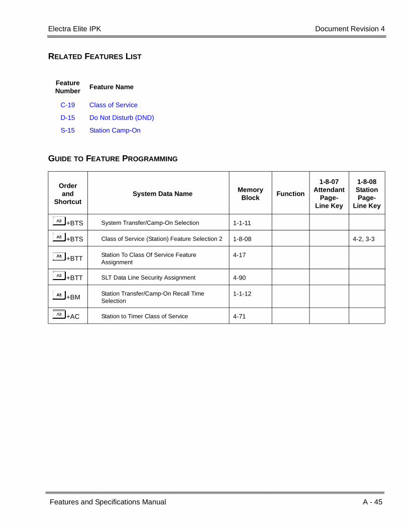
Electra Elite IPK Document Revision 4
Features and Specifications Manual A - 45
___________________________________________________________________________________
___________________________________________________________________________________
RELATED FEATURES LIST
GUIDE TO FEATURE PROGRAMMING
Feature Number
Feature Name
C-19 Class of Service
D-15 Do Not Disturb (DND)
S-15 Station Camp-On
Orderand
ShortcutSystem Data Name
Memory Block
Function
1-8-07Attendant
Page-Line Key
1-8-08StationPage-
Line Key
+BTS System Transfer/Camp-On Selection 1-1-11
+BTS Class of Service (Station) Feature Selection 2 1-8-08 4-2, 3-3
+BTTStation To Class Of Service Feature Assignment
4-17
+BTT SLT Data Line Security Assignment 4-90
+BMStation Transfer/Camp-On Recall Time Selection
1-1-12
+AC Station to Timer Class of Service 4-71
A - 46 Attendant Camp-On
___________________________________________________________________________________
___________________________________________________________________________________Document Revision 4 Electra Elite IPK
THIS PAGE INTENTIONALLY LEFT BLANK
Features and Specifications Manual A - 47
___________________________________________________________________________________
___________________________________________________________________________________
Attendant Positions A-13
FEATURE DESCRIPTION
Any number of stations can be designated an Attendant Position. These stations have access to distinct Attendant-type features. Two Attendant Positions can support two Attendant Add-On Consoles each. Programming for Attendant features such as setting Night Mode and System Speed Dial memory apply.
SYSTEM AVAILABILITY
Terminal Type:
Any Multiline Terminal with display programmed as an Attendant Position
Required Components:
None
OPERATING PROCEDURES
Provided under specific Attendant feature descriptions.
SERVICE CONDITIONS
Restrictions:
A maximum of four Attendant Add-On Consoles can be assigned to one Attendant Position.
A maximum of four Attendant Add-On Consoles can be assigned in the system.
Up to four Attendant positions can have an Attendant Add-on Console.
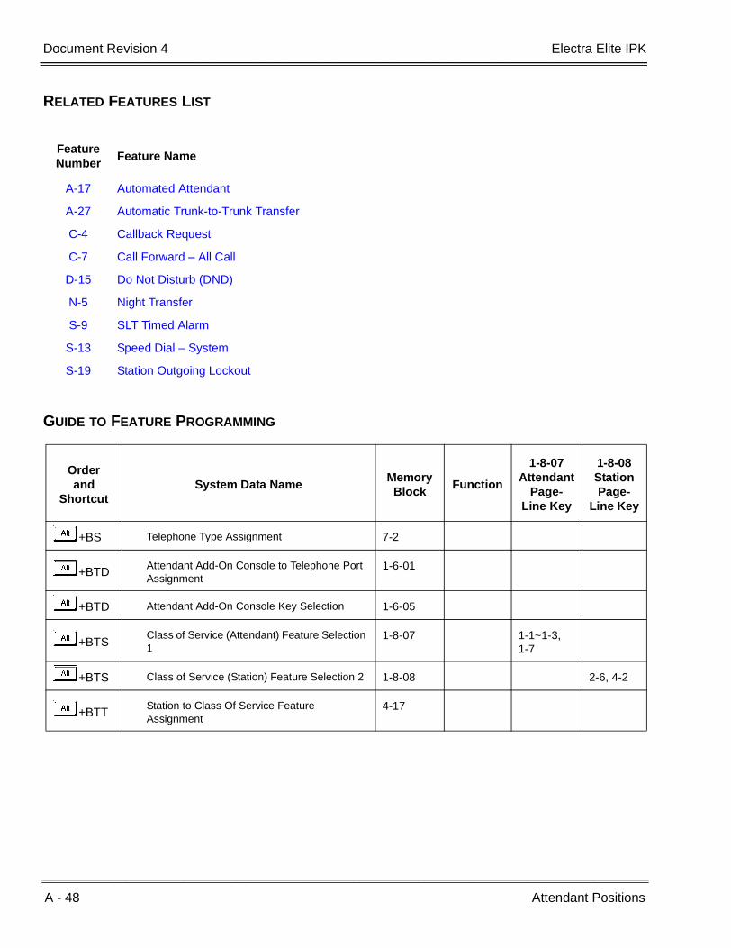
A - 48 Attendant Positions
___________________________________________________________________________________
___________________________________________________________________________________Document Revision 4 Electra Elite IPK
RELATED FEATURES LIST
GUIDE TO FEATURE PROGRAMMING
Feature Number
Feature Name
A-17 Automated Attendant
A-27 Automatic Trunk-to-Trunk Transfer
C-4 Callback Request
C-7 Call Forward – All Call
D-15 Do Not Disturb (DND)
N-5 Night Transfer
S-9 SLT Timed Alarm
S-13 Speed Dial – System
S-19 Station Outgoing Lockout
Orderand
ShortcutSystem Data Name
Memory Block
Function
1-8-07Attendant
Page-Line Key
1-8-08StationPage-
Line Key
+BS Telephone Type Assignment 7-2
+BTDAttendant Add-On Console to Telephone Port Assignment
1-6-01
+BTD Attendant Add-On Console Key Selection 1-6-05
+BTS Class of Service (Attendant) Feature Selection 1
1-8-07 1-1~1-3,1-7
+BTS Class of Service (Station) Feature Selection 2 1-8-08 2-6, 4-2
+BTTStation to Class Of Service Feature Assignment
4-17

Features and Specifications Manual A - 49
___________________________________________________________________________________
___________________________________________________________________________________
Attendant Station Outgoing Lockout A-14
FEATURE DESCRIPTION
Attendant Station Outgoing Lockout allows an Attendant Position with an Attendant Add-On Console to be used to set a predetermined Code Restriction Class Assignment at any station assigned on the Attendant Add-On Console. This allows an Attendant to set/reset a restriction to allow/deny an outgoing call.
SYSTEM AVAILABILITY
Terminal Type:
Any Multiline Terminal programmed as an Attendant Position
Required Components:
DCU-60-1/DCR-60-1 Console
OPERATING PROCEDURES
To set the Attendant Station Outgoing Lockout from the Attendant Position using the Attendant Add-On Console:
1. Press programmed Lockout key on the Attendant Add-On Console.
2. Press the DSS key on the Attendant Add-On Console that is associated with the station where Attendant Station Outgoing Lockout is desired.
3. The green LED next to the DSS key lights to indicate lockout is set.
A - 50 Attendant Station Outgoing Lockout
___________________________________________________________________________________
___________________________________________________________________________________Document Revision 4 Electra Elite IPK
To cancel the Attendant Station Outgoing Lockout from the Attendant Position using the Attendant Add-On Console:
1. Press the key programmed as Lockout key on the Attendant Add-On Console.
2. Press the DSS key on the Attendant Add-On Console that is associated with the station where Attendant Station Outgoing Lockout is to be canceled.
3. The green LED next to the DSS key turns off to indicate the lockout is canceled.
SERVICE CONDITIONS
General:
All Attendant Add-On Consoles can be used to set Attendant Station Outgoing Lockout.
Attendant Station Outgoing Lockout is retained by the memory backup battery.
No indication is provided at a terminal when Attendant Station Outgoing Lockout is set.
To confirm that Attendant Station Outgoing Lockout is set at an Attendant Add-On Console, ensure that the green LED associated with the station is On. Lockout remains set until canceled at the Attendant Add-On Console where it was set.
The station with Attendant Station Outgoing Lockout set cannot be used to manually cancel the lockout.
Restrictions:
An Attendant Add-On Console, with an Attendant Station Outgoing Lockout key assigned on it, cannot be used to set the Message Waiting feature from an Attendant.
When multiple Attendant Add-On Consoles are installed, the Attendant Station Outgoing Lockout is displayed only on the Attendant Add-On Console where the Lockout was set.
RELATED FEATURES LIST
Feature Number
Feature Name
M-2 Message Waiting
S-19 Station Outgoing Lockout
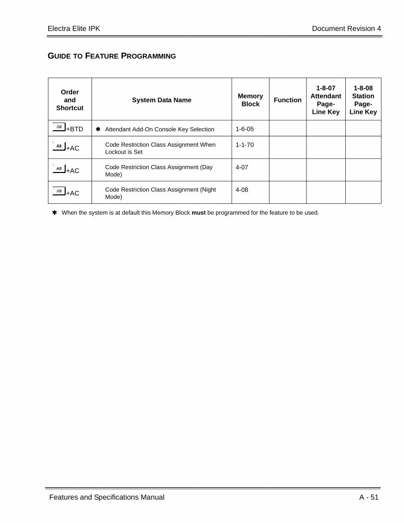
Electra Elite IPK Document Revision 4
Features and Specifications Manual A - 51
___________________________________________________________________________________
___________________________________________________________________________________
GUIDE TO FEATURE PROGRAMMING
Orderand
ShortcutSystem Data Name
Memory Block
Function
1-8-07Attendant
Page-Line Key
1-8-08StationPage-
Line Key
+BTD Attendant Add-On Console Key Selection 1-6-05
+ACCode Restriction Class Assignment When Lockout is Set
1-1-70
+ACCode Restriction Class Assignment (Day Mode)
4-07
+ACCode Restriction Class Assignment (Night Mode)
4-08
When the system is at default this Memory Block must be programmed for the feature to be used.

A - 52 Attendant Station Outgoing Lockout
___________________________________________________________________________________
___________________________________________________________________________________Document Revision 4 Electra Elite IPK
THIS PAGE INTENTIONALLY LEFT BLANK

Features and Specifications Manual A - 53
___________________________________________________________________________________
___________________________________________________________________________________
Attendant Transfer A-15
FEATURE DESCRIPTION
Attendant Transfer permits efficient call transfers in the system using an Attendant Multiline Terminal equipped with one to four Attendant Add-On Console(s). Transferred calls can be voice announced, camped-on (when the station is busy), or directly transferred to ring at stations. After a programmed time, all unanswered transferred calls return to the Attendant with distinct audible and visual indications.
SYSTEM AVAILABILITY
Terminal Type:
Any display Multiline Terminal programmed as an Attendant Position
Required Components:
DCU-60-1/DCR-60-1 Console
OPERATING PROCEDURES
From the Attendant Position with a CO/PBX call in progress:
1. Press the DSS key on the Attendant Add-On Console or the Attendant Position for the desired station.
2. Wait for ringback tone or voice announcement.
3. Press G on the Attendant Add-On Console or on the Attendant Position. The call is transferred.
4. Hang up.
5. After time-out, when the transferred call is not answered, a recall tone is received at the Attendant Position; and the LED on the assigned CO/PBX line key or Call Appearance Key flashes green.
6. Press the CO/PBX line key with the flashing green LED to return to the call.

A - 54 Attendant Transfer
___________________________________________________________________________________
___________________________________________________________________________________Document Revision 4 Electra Elite IPK
SERVICE CONDITIONS
General:
When a Transfer/Camp-On is denied, the call remains on hold at the Attendant Position.
The outside line key LED flashes green on the station receiving the Transfer/Camp-On, when the line appears on that station. The Large LED also flashes green and the LED or the ANS key flashes red.
An Attendant trying to Transfer/Camp-On a call to a station may be denied, when the Multiline Terminal is busy and receiving Tone Override.
Use Memory Block 4-66 (MOH or Ring Back Tone Selection) to assign MOH or Ring Back Tone for the outside party when a trunk call is placed on hold by the Transfer key on a Dterm, or hook flash from a Single Line Telephone, or the Transfer or Hold keys at a PSII station.
RELATED FEATURES LIST
Feature Number
Feature Name
A-11 Attendant Add-On Console
A-12 Attendant Camp-On
A-25 Automatic Release

Electra Elite IPK Document Revision 4
Features and Specifications Manual A - 55
___________________________________________________________________________________
___________________________________________________________________________________
GUIDE TO FEATURE PROGRAMMING
Orderand
ShortcutSystem Data Name
Memory Block
Function
1-8-07Attendant
Page-Line Key
1-8-08StationPage-
Line Key
+BTS System Transfer/Camp-On Selection 1-1-11
+BCS CO Transfer Ring Pattern Selection 1-1-13
+BCS CO Transfer Ring Tone Selection 1-1-14
+AU Class of Service (Station) Feature Selection 2 1-8-08 4-2
+BTD Attendant Add-On Console Key Selection 1-6-05
+BMStation Transfer/Camp-On Recall Time Selection
1-1-12
+AUAutomated Attendant Delay Announcement Hold Tone Selection
1-4-17
+BTT MOH or Ring Back Tone Selection 4-66
+AC Station to Timer Class of Service 4-71
When the system is at default this Memory Block must be programmed for the feature to be used.

A - 56 Attendant Transfer
___________________________________________________________________________________
___________________________________________________________________________________Document Revision 4 Electra Elite IPK
THIS PAGE INTENTIONALLY LEFT BLANKl

Features and Specifications Manual A - 57
___________________________________________________________________________________
___________________________________________________________________________________
Authorization Code A-16
FEATURE DESCRIPTION
Authorization Code permits a station user to dial outside numbers that would otherwise be restricted. When an access code plus Authorization Code is dialed, the station code restriction class temporarily changes to allow calls when permitted by a new code restriction class.
The Authorization Code can be verified or unverified based on class of service and is assigned in the Forced/Verified Account Code table (these share the same table).
The Authorization/Account Code is part of the Station Message Detail Recording (SMDR) call record.
SYSTEM AVAILABILITY
Terminal Type:
All stations
Required Components:
None
OPERATING PROCEDURES
To enter Forced Account Code/Authorization Code from any station:
1. Lift the handset or press E. .
2. Dial Forced Account Code/Authorization Code Access Code (not set at default).
3. Dial the Account Code.
4. Dial the trunk access code and the outside number.

A - 58 Authorization Code
___________________________________________________________________________________
___________________________________________________________________________________Document Revision 4 Electra Elite IPK
To program Forced Account Code/Authorization Code from Attendant position:
1. Lift the handset or press E .
2. Dial Forced Account Code/Authorization Code Programming Access Code (not set at default).
3. Dial the Forced Account Code/Authorization Code Number (001~500).
4. Dial the Account Code (default: 10 digits).
5. Press G to enter the information. The next Account Number is displayed. Repeat steps 4~5 until all desired Account Codes are entered.
6. Press E to stop entering Forced Account Codes/Authorization Codes.
SERVICE CONDITIONS
General
Use Memory Block 1-8-08 (Class of Service (Station) Feature Selection 2), Page 5, LK 1 to activate Forced Account Code/Authorization Code features.
Use Memory Block 1-8-08 (Class of Service (Station) Feature Selection 2), Page 6, LK 3 to activate Unverified for the Forced Account Code/Authorization Code features.
When a call is made without using an authorization code, memory blocks 4-64 and 4-65 are used to assign the code restriction class.
When a call is made using an authorization code, the code restriction class is temporarily changed and Memory Blocks 4-07 and 4-08 are used to assign the code restriction class.
After a call is placed using an authorization code, when the Recall or Drop keys are used, the temporary code restriction class remains with the setting assigned in Memory Blocks 4-07 and 4-08 allowing the user to dial another non-restricted number.
After placing a call using an authorization code, when the station goes idle (On-hook), the code restriction class is reset to its previous setting assigned in Memory Blocks 4-64 and 4-65.
A total of 500 Forced Account Codes/Authorization Codes can be entered system-wide.
Forced Account Codes/Authorization Codes and Account Code entries Codes are printed on the SMDR report, when both are used.
A is placed in front of the Forced Account Codes/Authorization Codes on the SMDR reports to distinguish them from other Account Code entries.
When the Interdigit time (default is 10 seconds) expires during the user input of a Forced Account Codes/Authorization Code, Busy Tone is generated.

Electra Elite IPK Document Revision 4
Features and Specifications Manual A - 59
___________________________________________________________________________________
___________________________________________________________________________________
PBR Time values apply when a Single line Telephone is used to enter a Forced Account Code/Authorization Code.
Forced Account Codes/Authorization Codes can be uploaded, downloaded, or modified using PC-based System Programming.
Restrictions
A Forced Account Code/Authorization Code has a maximum of 13 digits.
The Authorization Code feature is provided only from intercom dial tone. Direct access to trunks is bypassed by pressing CO Line Keys.
Existing restrictions (permitted by the temporary change to code restriction class) and Least Cost Routing (LCR) assignments are applied after Forced Account Codes/Authorization Codes are entered.
When a 911 call is placed, Forced Account Code/Authorization Code is overridden by the following:
Emergency 911 Cut-Through is enabled.
Enhanced 911 (CAMA Trunk) is installed and enabled.
Verified and Unverified Forced Account Code/Authorization Code cannot be used in the same Class of Service.
When 5-, 6-, or 7-digit station numbers are used, only the last four digits of the extension number are printed by SMDR.
RELATED FEATURES LIST
GUIDE TO FEATURE PROGRAMMING
Feature Number
Feature Name
A-2 Account Code – Forced/Verified/Unverified
C-21 Code Restriction
S-17 Station Message Detail Recording (SMDR)
Orderand
ShortcutSystem Data Name
Memory Block
Function
1-8-07Attendant
Page-Line Key
1-8-08StationPage-
Line Key
+BA Access Code (1-, 2-, or 3-Digit) Assignment 1-1-46~48 146, 147
+BTS Class of Service (Attendant) Feature Selection 1
1-8-07 2-8
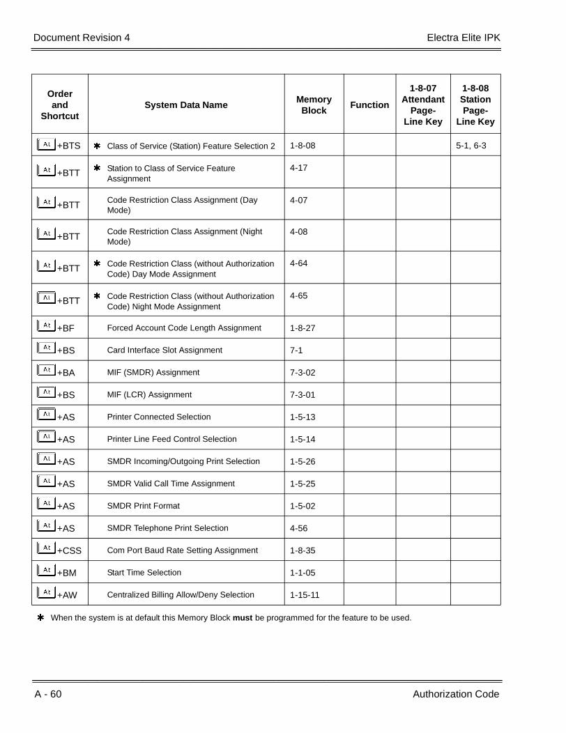
A - 60 Authorization Code
___________________________________________________________________________________
___________________________________________________________________________________Document Revision 4 Electra Elite IPK
+BTS Class of Service (Station) Feature Selection 2 1-8-08 5-1, 6-3
+BTT Station to Class of Service Feature Assignment
4-17
+BTTCode Restriction Class Assignment (Day Mode)
4-07
+BTTCode Restriction Class Assignment (Night Mode)
4-08
+BTT Code Restriction Class (without Authorization Code) Day Mode Assignment
4-64
+BTT Code Restriction Class (without Authorization Code) Night Mode Assignment
4-65
+BF Forced Account Code Length Assignment 1-8-27
+BS Card Interface Slot Assignment 7-1
+BA MIF (SMDR) Assignment 7-3-02
+BS MIF (LCR) Assignment 7-3-01
+AS Printer Connected Selection 1-5-13
+AS Printer Line Feed Control Selection 1-5-14
+AS SMDR Incoming/Outgoing Print Selection 1-5-26
+AS SMDR Valid Call Time Assignment 1-5-25
+AS SMDR Print Format 1-5-02
+AS SMDR Telephone Print Selection 4-56
+CSS Com Port Baud Rate Setting Assignment 1-8-35
+BM Start Time Selection 1-1-05
+AW Centralized Billing Allow/Deny Selection 1-15-11
When the system is at default this Memory Block must be programmed for the feature to be used.
Orderand
ShortcutSystem Data Name
Memory Block
Function
1-8-07Attendant
Page-Line Key
1-8-08StationPage-
Line Key
Features and Specifications Manual A - 61
___________________________________________________________________________________
___________________________________________________________________________________
Automated Attendant A-17
FEATURE DESCRIPTION
The Automated Attendant answers incoming CO/PBX calls and sends a greeting message to calling parties. When the caller enters a station number or a 1- or 2-digit number from the dial pad, as instructed in the greeting message, the Automated Attendant transfers the call to a designated station or Station Hunt group. The Automated Attendant can be set to provide eight automated message levels.
Incoming DID calls can be answered by the Automated Attendant.
SYSTEM AVAILABILITY
Terminal Type:
Not applicable
Required Components:
VRS(4)-U( ) ETU
OPERATING PROCEDURES
To record an Automated Attendant Message:
1. Go off-hook.
2. Dial the VRS Voice Message Record/Verify/Erase Access Code (e.g., EK).
3. Dial operation:
ARecording
BConfirmation
CErasing
A - 62 Automated Attendant
___________________________________________________________________________________
___________________________________________________________________________________Document Revision 4 Electra Elite IPK
4. Dial operation:
AAutomated Attendant
BVoice Prompt Message
CDelay Announcement
5. Enter Automated Attendant Message (A~H).
6. Enter Mode:
A Day Mode
B Night Mode
C Weekend Mode
7. Record Message.
8. Go on-hook.
To set the Automated Attendant Mode from the Attendant Position:
1. Press A .
2. Press HA.
3. Dial the incoming trunk number (KK~FD). KK indicates All CO/PBX lines.
Dialing 00 sets or cancels the Automated Attendant mode for all trunks when the trunks are idle.
A trunk that is busy when 00 is dialed is not set. To set the Automated Attendant to a busy trunk, dial the individual trunk number.
4. Press A .
To cancel the Automated Attendant Mode from the Attendant Position:
1. Press A .
2. Dial HB.
3. Dial the incoming trunk number (KK~FD). KK indicates All CO/PBX lines.
Dialing 00 sets or cancels the Automated Attendant mode for all trunks when the trunks are idle. A trunk that is busy when 00 is dialed is not set. To set the Automated Attendant to a busy trunk, dial the individual trunk number.
4. Press A .

Electra Elite IPK Document Revision 4
Features and Specifications Manual A - 63
___________________________________________________________________________________
___________________________________________________________________________________
To set/cancel the Weekend Mode from the Attendant Position:
1. Press A .
2. Dial HF.
3. Dial tenant number (KK~DG).
All trunks for the dialed tenant are set/canceled for the weekend mode.
4. Press A .
To answer by One Level:
1. Receive an incoming CO/PBX call.
2. The Automated Attendant answers the call and sends a greeting.
3. A DTMF tone is received. Each tone is assigned to a station number or a station hunt group.
4. The call is transferred to a designated station or station hunt group.
5. The called party answers and talks.
To answer by Multiple Levels (up to eight levels are available):
1. Receive an incoming CO/PBX call.
2. The Automated Attendant answers the call and sends a greeting.
3. A 1-digit DTMF tone is received. Each tone is assigned to another message on the VRS ETU.
4. The call is answered by the VRS(4)-U( ) ETU and another message is played.
5. A 1-, 2-, or 3-digit DTMF signal is received.
6. The call is transferred to a designated station of the second level, or another VRS(4)-U( ) ETU message is played.
7. The called party answers and talks.
A - 64 Automated Attendant
___________________________________________________________________________________
___________________________________________________________________________________Document Revision 4 Electra Elite IPK
Timeout - No Answer:
1. An incoming CO/PBX call is received on a line.
2. The Automated Attendant answers the call and sends a greeting.
3. A 1-digit DTMF tone is received.
4. The call is transferred to a designated station or Station Hunt group.
5. When there is no answer, the CO/PBX ringing transfer at the station is changed to an ordinary CO/PBX ringing call on the CO/PBX line, after a programmed time.
6. The calling party on the CO/PBX line is answered.
SERVICE CONDITIONS
General:
A maximum of two VRS(4)-U( ) ETUs can be used for Automated Attendant.
Each channel has 240 recording seconds that can be subdivided into 2, 4, 8, or 16 equal recording times.
A maximum of eight Automated Attendants can be assigned. Multiple Automated Attendants can be assigned to one VRS(4)-U( ) ETU channel.
When the VRS(4)-U( ) ETU or PBR is busy and a CO/PBX call is incoming, the caller hears a ringback tone until a VRS channel and PBR are available.
When Automated Attendant or PBR is busy, after the call is transferred to the second level, a ringback tone is sent to the calling party.
DIT/ANA assigned to the same trunk has higher priority.
Automated Attendant and system Access Codes can be assigned individually.
Automated Attendant is assigned to tenants and follows the tenants Day/Night/Weekend mode switching.
When Automated Attendant answer is assigned for a trunk and a VRS(4)-U( ) ETU is not installed, second dial tone is provided for incoming callers.
Electra Elite IPK Document Revision 4
Features and Specifications Manual A - 65
___________________________________________________________________________________
___________________________________________________________________________________
When an incoming caller is transferred to a busy station, the following options are available to this caller:
Restrictions:
CPUI( )-U( ) ETU circuits are used for this feature. The CPUI( )-U( ) ETU has four built-in PBR circuits that can be programmed for use with the Automated Attendant, DISA feature, or Single Line Telephones. When all four circuits are set for AA/DISA using Memory Block 1-8-01 (SLT or Automated Attendant/DISA to CPU PBR Selection), a PBR ETU must be installed for Single Line Telephone use.
Automatic Trunk-to-Trunk Transfer and Automated Attendant cannot be set for the same trunk at the same time.
Memory Block 1-4-02 (Automated Attendant Transfer Delayed Ringing Time Selection) must time out before incoming DID calls can be answered by the Automated Attendant (cannot be set to No Limit).
Memory Block 1-4-02 (Automated Attendant Transfer Delayed Ringing Time Selection) is not required to time out before incoming DID calls can be answered by the Automated Attendant (can be set to No Limit).
Only trunks assigned in Memory Block 3-05 (Trunk Incoming Answer Mode Selection) for AA are set or canceled for Automated Attendant/DISA Mode when an Attendant position enters 00 during the set or cancel operation.
Use Memory Block 1-4-08 (Automated Attendant PBR Timeout Response Selection) to specify how a call is answered by the Automated Attendant when a DTMF tone is not received. When NORMAL Call is specified (default), the system rings selected stations using Memory Block 4-01[CO/PBX Ring Assignment (Day Mode)] or 4-02 [CO/PBX Ring Assignment (Night Mode)]. When RELEAS is specified, the call is dropped after a fixed time of 30 seconds.
Dial Action
A Step Call is performed
J Second dial tone is provided
L Ringing begins based on the Day/Night ringing assignment

A - 66 Automated Attendant
___________________________________________________________________________________
___________________________________________________________________________________Document Revision 4 Electra Elite IPK
RELATED FEATURES LIST
GUIDE TO FEATURE PROGRAMMING
Feature Number
Feature Name
A-10 Assigned Night Answer (ANA)
D-10 Direct Inward System Access (DISA)
D-11 Direct Inward Termination (DIT)
Orderand
ShortcutSystem Data Name
Memory Block
Function
1-8-07Attendant
Page-Line Key
1-8-08StationPage-
Line Key
+BS Card Interface Slot Assignment 7-1
+BCT Trunk Type Selection 3-91
+BCT Trunk-to-Trunk Group Assignment 3-03
+AR VRS Message Recording Time Selection 1-8-12
+AR VRS Message Function Assignment 1-8-13
+AUAutomated Attendant Extension Number Assignment
1-4-21
+AUAutomated Attendant Direct Extension Ring Assignment
1-4-22
+BA Access Code (1-, 2-, or 3-Digit) Assignment 1-1-46/47/48 501
+AU Automated Attendant Message Day/Night Mode Selection
1-4-11
+BTI SLT or Automated Attendant/DISA to PBR Selection
1-8-01
+BCT Trunk Incoming Answer Mode Selection 3-05
+AU Automated Attendant Function Selection 3-59
+AUAutomated Attendant Message to Trunk Selection
3-38
+BMAutomatic Day/Night Mode by Day of Week Selection
1-1-32

Electra Elite IPK Document Revision 4
Features and Specifications Manual A - 67
___________________________________________________________________________________
___________________________________________________________________________________
+AU Hold Tone Automated Attendant Selection 3-65
+AUAutomated Attendant Message to Tenant Assignment
1-4-12
+BTS Class of Service (Attendant) Feature Selection 1
1-8-07 1-1, 1-2, 1-8, 2-7
+BTSClass of Service (Station) FeatureSelection 2
1-8-08 2-6
+BTTStation to Class of Service Feature Assignment
4-17
+AUAutomated Attendant Message Access Code (1-Digit) Assignment
1-4-14
+AUAutomated Attendant Message Access Code (2-Digit) Assignment
1-4-15
+BA Specified Station Access Code Assignment 1-2-08
+AUAutomated Attendant Answer Delay Time Assignment
1-4-13
+AUAutomated Attendant Message Repeat Selection
1-4-16
+AUAutomated Attendant PBR Start Time Selection
1-4-09
+AUAutomated Attendant First Digit PBR Release Time Selection
1-4-01
+AU Automated Attendant Selection for DID 4-58
+AUAutomated Attendant PBR Timeout Response Selection
1-4-08
+AUPBR Receive Level Assignment for Automated Attendant/DISA
1-8-02
+AUAutomated Attendant Transfer Delayed Ringing Time Selection
1-4-02
+AU Automated Attendant Transfer Ring Pattern 1-1-54
+AUAutomated Attendant No Answer Disconnect Time Selection
1-4-03
Orderand
ShortcutSystem Data Name
Memory Block
Function
1-8-07Attendant
Page-Line Key
1-8-08StationPage-
Line Key

A - 68 Automated Attendant
___________________________________________________________________________________
___________________________________________________________________________________Document Revision 4 Electra Elite IPK
+AUAutomated Attendant Delay Announcement Hold Tone Selection
1-4-17
+ALN DID Digit Length Selection 1-1-20
+ALN DID Digit Conversion Assignment 1-1-21
+ALN DID Digit Conversion Table 1-1-22
+ALNDID Forward Station Number for Busy Station or Undefined Digit
1-1-23
+BTM Line Key Selection for Telephone Mode 4-12
+BTT CO/PBX Ring Assignment (Day Mode) 4-01
+BTT CO/PBX Ring Assignment (Night Mode) 4-02
+BITone Assignment 1-8-15 Tone
Table 01
+ATTandem Transfer SMDR Print Extension Assignment
1-4-04
+BMAutomatic Day/Night Mode Switching Time Assignment
1-1-27
When the system is at default this Memory Block must be programmed for the feature to be used.
Orderand
ShortcutSystem Data Name
Memory Block
Function
1-8-07Attendant
Page-Line Key
1-8-08StationPage-
Line Key

Features and Specifications Manual A - 69
___________________________________________________________________________________
___________________________________________________________________________________
Automatic Answer with Delay Message A-18
FEATURE DESCRIPTION
Automatic Answer with Delay Message answers an incoming CO/PBX call and plays a specified message to the outside caller while still ringing the designated station. Up to two messages can be played to the outside caller. The message(s) played are the same as the Automated Attendant message(s).
SYSTEM AVAILABILITY
Terminal Type:
Not applicable
Required Components:
VRS(4)-U( ) ETU
OPERATING PROCEDURES
To record an Automated Attendant Message:
1. Go off-hook.
2. Dial the VRS Voice Message Record/Verify/Erase Access Code (e.g., EK).
3. Dial operation:
A Recording
B Confirmation
C Erasing
4. Dial operation:
A Automated Attendant
5. Enter Automated Attendant Message (A~H).

A - 70 Automatic Answer with Delay Message
___________________________________________________________________________________
___________________________________________________________________________________Document Revision 4 Electra Elite IPK
6. Enter Mode:
ADay Mode
B Night Mode
7. Record Message.
8. Go on-hook.
To set the Automated Attendant/Delay Message Mode from the Attendant Position:
1. Press A .
2. Dial HA.
3. Dial the incoming trunk number (KK~FD). KK indicates All CO/PBX lines.
Dialing 00 sets or cancels the Automated Attendant mode for all trunks when the trunks are idle. A trunk that is busy when 00 is dialed is not set. To set the Automated Attendant to a busy trunk, dial the individual trunk number.
4. Press A .
To cancel the Automated Attendant/Delay Message Mode from the Attendant Position:
1. Press A .
2. Dial HB.
3. Dial the incoming trunk number (KK~FD). KK indicates All CO/PBX lines.
Dialing 00 sets or cancels the Automated Attendant mode for all trunks when the trunks are idle. A trunk that is busy when 00 is dialed is not set. To set the Automated Attendant to a busy trunk, dial the individual trunk number.
4. Press A .
To answer by One Level:
1. Receive an incoming CO/PBX call.
2. The Automatic Answer with Delay Message answers the call and sends a greeting.
3. The outside party hears ringback tone or MOH (System Programmed).

Electra Elite IPK Document Revision 4
Features and Specifications Manual A - 71
___________________________________________________________________________________
___________________________________________________________________________________
To answer by Two Levels:
1. Receive an incoming CO/PBX call.
2. The Automatic Answer with Delay Message answers the call and sends a greeting.
3. The outside party hears ringback tone or MOH (System Programmed).
4. After the time expires, a second message is played.
5. The outside party hears ringback tone or MOH until the call is answered.
SERVICE CONDITIONS
General:
A maximum of two VRS(4)-U( ) ETUs, four channels per ETU, can be used for Automated Attendant.
Each channel has 240 recording seconds that can be subdivided into 2, 4, 8, or 16 equal recording times.
A maximum of eight Automated Attendants can be assigned.
The Automatic Answer with Delay Message feature uses the Automated Attendant Message to play to the outside caller.
DIT/ANA assigned to the same trunk has higher priority.
Automated Attendant and system Access Codes can be assigned individually.
Automated Attendant is assigned to tenants and follows the tenants Day/Night/Weekend mode switching.
When Automated Attendant answer is assigned for a trunk and a VRS(4)-U( ) ETU is not installed, second dial tone is provided for incoming callers.
Restrictions:
Tie/DID lines are not supported by the Automatic Answer with Delay Message feature.
DTMF digits cannot be dialed by the outside caller while in the Automatic Answer with Delay Message mode.
CPUI( )-U( ) ETU PBR circuits are not used for this feature.
Automatic Answer with Delay Message or Automated Attendant is assigned per trunk.

A - 72 Automatic Answer with Delay Message
___________________________________________________________________________________
___________________________________________________________________________________Document Revision 4 Electra Elite IPK
Automatic Trunk-to-Trunk Transfer and Automated Attendant cannot be set for the same trunk at the same time.
RELATED FEATURES LIST
GUIDE TO FEATURE PROGRAMMING
Feature Number
Feature Name
D-10 Direct Inward System Access (DISA)
Orderand
ShortcutSystem Data Name
Memory Block
Function
1-8-07Attendant
Page-Line Key
1-8-08StationPage-
Line Key
+BS Card Interface Slot Assignment 7-1
+BTI SLT or Automated Attendant/DISA to CPU PBR Selection
1-8-01
+AR VRS Message Recording Time Selection 1-8-12
+AR VRS Message Function Assignment 1-8-13
+AU Automated Attendant Message Day/Night Mode Selection
1-4-11
+AUAutomated Attendant Message to Tenant Assignment
1-4-12
+AUAutomated Attendant Answer Delay Time Assignment
1-4-13
+AUAutomated Attendant Message Repeat Selection
1-4-16
+AUAutomated Attendant Delay Announcement Hold Tone Selection
1-4-17
+AU Automated Attendant Delay Announcement Assignment
1-4-18
+AU Automated Attendant 1st to 2nd Delay Announcement Interval Time
1-4-19
+AU Automated Attendant Delay Announcement Disconnect Time
1-4-20

Electra Elite IPK Document Revision 4
Features and Specifications Manual A - 73
___________________________________________________________________________________
___________________________________________________________________________________
+BCT Trunk Incoming Answer Mode Selection 3-05
+AUAutomated Attendant Message to Trunk Selection
3-38
+AU Automated Attendant Function Selection 3-59
+BA Access Code (1-, 2-, or 3-Digit) Assignment 1-1-46/47/48 501
+BTT CO/PBX Ring Assignment (Day Mode) 4-01
+BTT CO/PBX Ring Assignment (Night Mode) 4-02
+BTSClass of Service (Attendant) Feature Selection 1
1-8-07 1-8
+BTS Class of Service (Station) Feature Selection 2 1-8-08 2-6
When the system is at default this Memory Block must be programmed for the feature to be used.
Orderand
ShortcutSystem Data Name
Memory Block
Function
1-8-07Attendant
Page-Line Key
1-8-08StationPage-
Line Key
A - 74 Automatic Answer with Delay Message
___________________________________________________________________________________
___________________________________________________________________________________Document Revision 4 Electra Elite IPK
THIS PAGE INTENTIONALLY LEFT BLANK
Features and Specifications Manual A - 75
___________________________________________________________________________________
___________________________________________________________________________________
Automatic Callback A-19
FEATURE DESCRIPTION
After receiving a call waiting tone from a busy station, a user can set Automatic Callback when allowed in Class of Service (Station). When both stations are idle, the system signals the Automatic Callback originator first and, after the originator answers, signals the other station.
SYSTEM AVAILABILITY
Terminal Type:
All Multiline Terminals
Required Components:
None
OPERATING PROCEDURES
To use this feature after calling a busy station and receiving a call waiting tone:
1. Dial Access Code K (set as default).
2. Hang up.
3. The originating station rings when both stations become idle.
4. Lift the handset or press E .
5. Receive tone burst or ringback tone; talk when the called station user answers.
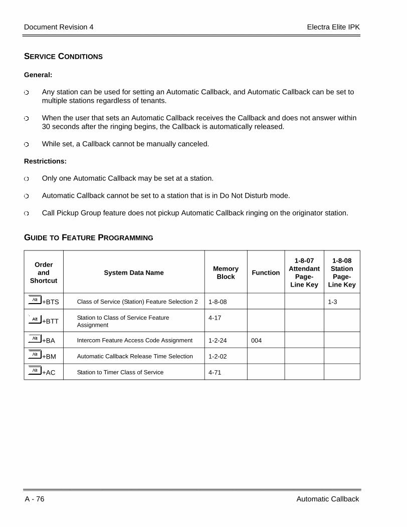
A - 76 Automatic Callback
___________________________________________________________________________________
___________________________________________________________________________________Document Revision 4 Electra Elite IPK
SERVICE CONDITIONS
General:
Any station can be used for setting an Automatic Callback, and Automatic Callback can be set to multiple stations regardless of tenants.
When the user that sets an Automatic Callback receives the Callback and does not answer within 30 seconds after the ringing begins, the Callback is automatically released.
While set, a Callback cannot be manually canceled.
Restrictions:
Only one Automatic Callback may be set at a station.
Automatic Callback cannot be set to a station that is in Do Not Disturb mode.
Call Pickup Group feature does not pickup Automatic Callback ringing on the originator station.
GUIDE TO FEATURE PROGRAMMING
Orderand
ShortcutSystem Data Name
Memory Block
Function
1-8-07Attendant
Page-Line Key
1-8-08StationPage-
Line Key
+BTS Class of Service (Station) Feature Selection 2 1-8-08 1-3
+BTTStation to Class of Service Feature Assignment
4-17
+BA Intercom Feature Access Code Assignment 1-2-24 004
+BM Automatic Callback Release Time Selection 1-2-02
+AC Station to Timer Class of Service 4-71

Features and Specifications Manual A - 77
___________________________________________________________________________________
___________________________________________________________________________________
Automatic Call Distribution A-20
FEATURE DESCRIPTION
Automatic Call Distribution forwards any incoming trunk call (DIT, ANA, DID, or CO Ring Transfer) to a selected ACD Group of Agents. An incoming call is distributed to the ACD Group Agent that has been idle the longest. The ACD feature has four distinct parts: Call Distribution, Agents and Supervisor Function, Status screens and Management Information System (MIS) reports, and Delay Announcement.
SYSTEM AVAILABILITY
Terminal Type:
All Multiline Terminals
Required Components:
MIFA-U( ) with KMA(1.0)U for ACD
- OR -
SPE(M)-U10 ETU
VRS(4)-U( ) ETU for Delay Announcement.
OPERATING PROCEDURES
Refer to the Automatic Call Distribution Manual.

A - 78 Automatic Call Distribution
___________________________________________________________________________________
___________________________________________________________________________________Document Revision 4 Electra Elite IPK
CALL PROCESSING
GENERAL DESCRIPTION
The following features are included:
Abandoned Call Search
Abandoned incoming calls are not connected to Agent Positions. The system can recognize abandoned calls and remove them from the queue on trunks that provide calling party disconnect supervision.
Call Distribution to Agents
Calls are automatically and uniformly distributed among Agents in an ACD Group. Calls are distributed to the longest idle Agent Position. When incoming calls are held, the oldest call is connected to the first available Agent position.
Call Transfer to ACD Group Queue
CO Trunk calls that terminate to either a normal station, ACD Agent, or Supervisor Position may be transferred to an ACD group queue.
Night Service
When the ACD group is placed in Night Mode, the system can route all incoming ACD calls to one of the following: Internal Station, Night Announcement, transfer to the Attendant, or Trunk-to-Trunk Transfer.
Overflow
Overflow Service allows calls held in queue for more than a programmed time to be directed to an assigned station or Station Hunt group, but not to overflow to another group.
Queuing
All incoming calls destined for ACD groups are placed in queue when no Agent in the ACD group is presently available to handle the call. Queue is used to provide service in order of arrival (first in-first out).
Pilot Numbers
Pilot numbers (Access Codes to ACD functions) are programmed in the System Data according to the numbering plan in effect for the system. Pilot numbers do not correspond to any line appearance in the Electra Elite systems. No hardware equipment is required to assign a Pilot number. An ACD Group Pilot number should not be programmed in a Station Hunt group. The Station Hunt feature takes priority over the ACD function.

Electra Elite IPK Document Revision 4
Features and Specifications Manual A - 79
___________________________________________________________________________________
___________________________________________________________________________________
SERVICE CONDITIONS
General:
When the Agent (in the ACD group where a call is terminated) does not answer for a programmed time, the call is transferred to another Agent in the ACD group.
When the Agents (in the ACD group where a call is terminated) are all busy, the call waits in a queue until an Agent is available. The caller receives a Delay Announcement and Music On Hold. Calls are answered first-in, first-out.
When the overflow destination station is busy, calls continue searching the ACD group for an available Agent.
When an incoming call to an ACD group encounters all ACD Agents busy or no answer, the call is queued and the caller receives a recorded announcement (Delay Announcement) after a programmed time.
The ACD group is assigned a Pilot number. Calls directed to the Pilot number are directed to Agents of that ACD group.
The following maximum assignments for programming ACD groups and Agents are:
Up to 32 Agents can be programmed per system.
Up to four ACD Groups can be assigned per system.
Up to 32 Agents can be assigned in one ACD group.
All trunks used for ACD incoming calls must provide a receiving remote disconnect signal to release abandoned calls.
Overflow is performed only once.
When the overflow destination station is set for Call Forward to an ACD Group, overflow does not occur.
A Voice Mail Hunt group can be assigned as the destination station for ACD overflow; however, no DTMF digits are sent to the voice mail system.
Restrictions:
Alert tone is not provided even when all Agents in the ACD group are busy. However, Pooled Line (Outgoing) can indicate the status of trunks in an ACD group as an alternate method.
When 5-, 6-, or 7-digit station numbers are used, this feature is not available.
A - 80 Automatic Call Distribution
___________________________________________________________________________________
___________________________________________________________________________________Document Revision 4 Electra Elite IPK
AGENT AND SUPERVISOR FUNCTION
GENERAL DESCRIPTION
The following features are included:
Assistance
This feature allows an Agent to call a Supervisor in the ACD group for assistance. Activation of this feature during an ACD call, automatically places the active call on hold and places an assistance call to the Supervisor. This feature uses a Feature Access or One-Touch key.
Break Mode
This feature allows the Agent to take a position out of the ACD mode without logging off. Break Mode is used for breaks from work (e.g., lunch or coffee breaks). This feature uses the DND key that is programmed on a Feature Access or One-Touch key.
Logon/Logoff
This feature allows an Agent to logon/logoff the system. Operating statistics are collected for the Agent until they logoff. This feature is activated by the Logon/Logoff key that is programmed on a Feature Access or One-Touch key on the Agent Position.
Non-ACD Call
This feature allows an Agent or Supervisor to receive a call directly from dial trunks (e.g., Tie line, DID, or DIT) or a transferred call to the agent. Transfer ACD calls from another Agent or ACD calls on hold by another Agent are counted as non-ACD calls by MIS when they are picked up by another Agent.
Answer/Release-Headset
This feature uses the Headset On/Off key that is assigned on a line key in System Programming to allow an Agent using a headset to answer or release an ACD call.
Volume Control-Headset
This feature allows an Agent to control the receiving level at a station, independent of the level of the incoming calls.
Control of Night Mode
This feature can be activated and deactivated by the NT key that is programmed on a Feature Access or One-Touch key on the Supervisor terminal to allow the Supervisor to activate Night Mode.
Monitoring (Barge-In)
This feature allows the Supervisor to monitor calls at an Agent Position and is activated by key operation on the Supervisor Terminal. During monitoring, the Conference LED at both terminals is On.

Electra Elite IPK Document Revision 4
Features and Specifications Manual A - 81
___________________________________________________________________________________
___________________________________________________________________________________
SERVICE CONDITIONS
General:
When a call is transferred to an ACD Pilot number using a Call Appearance key, the LED stays On until the call is answered and released by an Agent.
When the Agent is in Break Mode, the Busy Lamp Field (BLF) flashes red.
Any Agent in an ACD group can busy out a station by pressing the Logoff key on the Multiline Terminal. When log off is activated, the station user can receive a call directed to the station number (but not the ACD group number) and originate calls.
During Break Mode, an incoming ACD call cannot be received.
ACD MIS interfaces with the Electra-Stat ACD/MIS or Elite Stat Plus application software.
Any non-ACD call that is transferred or Direct Terminal Interfaced to a station that is logged on as an ACD agent follows any Call Forwarding that is set.
Restrictions:
Agents can log off or enter Break Mode only when their station is idle.
When an Agent logs on with an outside call on hold, the status of the Agent on the MIS terminal shows Available, but the system does not distribute an ACD call to the Agent until the held call is terminated or transferred to another user.
While an ACD Agent is logged on, the ACD calls do not follow any forwarding on the telephones.
ACD Agents do not receive another ACD call when an existing ACD call is on hold or is call parked. When the held or call parked call is terminated, the ACD Agent can receive ACD calls again.
Call Forwarding can be set or canceled only while the agent is logged out of ACD.
When using 5-, 6-, or 7-digit station numbers, this feature is not available.

A - 82 Automatic Call Distribution
___________________________________________________________________________________
___________________________________________________________________________________Document Revision 4 Electra Elite IPK
STATUS SCREENS AND MANAGEMENT INFORMATION SYSTEM (MIS) REPORTS
DESCRIPTION
The Elite Stat Plus Management Information System (MIS) software provides a cost effective means to manage incoming telephone traffic and associated staff activity. The ACD/MIS feature provides real-time statistical reports with readily accessible help screens.
ACD/MIS runs on an external PC that uses an Open Applications Interface (OAI) channel to communicate with the Electra Elite IPK. ACD/MIS operates in conjunction with the Log on, Log off, and Break features of the associated Electra Elite IPK.
Elite Stat Plus has two main system components:
Elite Stat Plus Server
Elite Stat Plus Monitor Client
Elite Stat Plus Server
The Elite Stat Plus Server program sets up communication with the NEC KSU and recording call activity to an external database. The server should be running at all times to properly store call records. The server can run in a foreground or background window, and as an icon. The server application is added to the startup tasks to allow auto-start when the PC is turned on.
The Server PC should be a dedicated system reserved exclusively for Elite Stat Plus programs. Once initiated, the program begins to accept data from the KSU after 15 ~ 20 seconds.
Elite Stat Plus must be running to properly collect all call record activity (i.e. the program must either be active or minimized).
Elite Stat Plus Monitor Client
The Elite Stat Plus Monitor Client program can run on the Server PC or run on a networked PC (client). A password is not required to run the Monitor client; however, only a maximum number of five simultaneous Monitors can be active.
When Elite Stat Plus Monitor is started on the same PC as the server, it registers with the server and begins displaying ACD group data immediately. When the program determines that it is running on a network machine, the operator must enter the network address or network machine name of the Server PC. At that time the monitor is registered with the server and the ACD group data is displayed.
When running in real-time mode, the Monitor displays a screen at start-up to show real-time queue information. From within the real-time screen, select a particular report from the Reports menu to obtain historical call information for viewing or printing.

Electra Elite IPK Document Revision 4
Features and Specifications Manual A - 83
___________________________________________________________________________________
___________________________________________________________________________________
The Monitor user interface provides real-time queue information for all ACD groups:
The current status of all agents
The selected report in graph format
The queue statistics (number of agents logged in, number of calls in queue, and longest wait time of calls in queue)
ACD group call statistics per user-defined period (number of abandoned calls, number of answered calls)
An ACD group call summary for user-defined period (average time talking with agent and average hold time)
For additional information, refer to the Elite Stat Plus ACD/MIS Owner’s Manual.
REAL TIME DISPLAY (RTD)
DESCRIPTION
The Real Time Display (RTD) consists of a server application that is installed on the same PC running the ACD Plus server software, and client software that is installed on Agent PCs. This application provides real time queue and agent status information to the individual desktop as a cost effective alternative to expensive wall displays. In addition to the queue and agent status information, the application also allows text messaging to be sent to individual agents and groups of agents.
Elite Stat Plus Software Suite is required to support RTD feature.
A sample display of the RTD is shown below.
A - 84 Automatic Call Distribution
___________________________________________________________________________________
___________________________________________________________________________________Document Revision 4 Electra Elite IPK
SERVICE CONDITIONS
General:
An optional RTD License Key is available to support additional RTD clients.
Without an RTD License Key, up to three RTD clients are supported.
With an RTD License Key, up to 100 RTD clients are supported.
For each queue, the RTD lists the following statistics:
Number of agents logged into the queue
Number of calls waiting in the queue
Wait time of the call that has been in the queue the longest
By default, the top line on the Real Time Display shows the headers for each statistic column. The bottom row of the Real Time Display shows text messages as they are received from other users.
The following appearances of RTD can be customized:
Turning headers off/on
Resizing
Repositioning
Keeping the RTD image visible
The Real Time Display application is controlled through settings in the ACD Plus Server that allow text messages to be sent between RTD clients. General announcements can be made to groups of users or direct comments can be made to individual agents. All RTD clients can receive text messages.
A text message received by an RTD Client is scrolled across the bottom line of the display. The message continues to scroll until the message duration has expired or the user selects the Clear function. When multiple messages are received, the messages are displayed in sequence, in the order in which they were received.
A threshold can be defined on the ACD Plus Server for each statistic shown on the Real Time Display. The threshold represents critical levels that indicate the efficiency of the call center operations. Threshold levels are shown on the RTD by the color of the individual statistic when the threshold is reached. Green indicates an acceptable level. Yellow indicates a warning level. Red indicates a critical level.
The RTD can also provide additional alerts (a Tone or a Popup) as threshold levels are reached.
Electra Elite IPK Document Revision 4
Features and Specifications Manual A - 85
___________________________________________________________________________________
___________________________________________________________________________________
Restrictions:
The PC requirements for an Elite Stat Plus Software Suite running the RTD feature include:
Software Requirements
Microsoft Windows 98, 2000, Me, or XP
Hardware Requirements
IBM-compatible machine with at least a 500 Mhz CPU
Elite Stat and RTD Server — 256 MB RAM
RTD Client — 128 MB RAM
Minimum 40 MB of available hard disk space
CD-ROM drive
Unused serial port for connecting to the KSU
Mouse
Printer (optional)
RELATED FEATURES LIST
GUIDE TO FEATURE PROGRAMMING
Feature Number
Feature Name
D-2 Delay Announcement
Orderand
ShortcutSystem Data Name
Memory Block
Function
1-8-07Attendan
tPage-
Line Key
1-8-08StationPage-
Line Key
+BS Card Interface Slot Assignment 7-1
+BS MIF (ACD) Assignment 7-3-00
+BA Access Code (1-, 2-, or 3-Digit) Assignment 1-1-46/47/48
031, 032,040
+AA ACD/UCD Group Pilot Number Assignment 1-12-00

A - 86 Automatic Call Distribution
___________________________________________________________________________________
___________________________________________________________________________________Document Revision 4 Electra Elite IPK
+AA ACD/UCD Group Agent Assignment 1-8-25
+BTSClass of Service (Station) Feature Selection 2
1-8-08 1-1, 1-4,1-5
+BTTStation to Class of Service Feature Assignment
4-17
+AAACD/UCD Group Overflow Destination Assignment
1-12-01
+AA ACD/UCD Overflow Time Selection 1-12-02
+BCT DIT Assignment 3-42
+BCT ANA Assignment 3-43
+BTM Line Key Selection for Telephone Mode 4-12
+BTMExtension Line Key Ring Assignment (Day Mode)
4-37
+BTMExtension Line Key Ring Assignment (Night Mode)
4-38
+BTS Barge-In Alert Tone Assignment 1-1-76
+AA ACD Hunt Time 1-8-40
When the system is at default this Memory Block must be programmed for the feature to be used.
Orderand
ShortcutSystem Data Name
Memory Block
Function
1-8-07Attendan
tPage-
Line Key
1-8-08StationPage-
Line Key
Features and Specifications Manual A - 87
___________________________________________________________________________________
___________________________________________________________________________________
Automatic Day/Night Mode Switching A-21
FEATURE DESCRIPTION
Automatic Day/Night Mode switching programs the system to switch automatically in or out of the Night Mode at a programmed time. This eliminates the daily need to manually set/reset the Night Mode. After a programmed time, the system automatically switches back to Day Mode.
SYSTEM AVAILABILITY
Terminal type:
Not applicable
Required Components:
None
OPERATING PROCEDURES
None
SERVICE CONDITIONS
General:
Two separate Day/Night Mode switch times are available. In any 24 hour period, the system changes from night mode to day mode at a specified time, then later the system changes from day mode back to night mode at a specified time.
Station Code Restriction Class Assignment may also change automatically when the system goes into Night Mode.
This feature switches Day/Night Mode for all tenants.

A - 88 Automatic Day/Night Mode Switching
___________________________________________________________________________________
___________________________________________________________________________________Document Revision 4 Electra Elite IPK
GUIDE TO FEATURE PROGRAMMING
Orderand
ShortcutSystem Data Name
Memory Block
Function
1-8-07Attendant
Page-Line Key
1-8-08StationPage-
Line Key
+BM Automatic Day/Night Mode Switching Time Assignment
1-1-27
+BM Automatic Day/Night Mode by Day of Week Selection
1-1-32
+BTSClass of Service (Attendant) Feature Selection 1
1-8-07 1-1,1-2
+BM Automatic Daylight Saving Time Selection 1-8-48
+BTT CO/PBX Ring Assignment (Day Mode) 4-01
+BTT CO/PBX Ring Assignment (Night Mode) 4-02
+BTMExtension Line Key Ring Assignment (Day Mode)
4-37
+BTMExtension Line Key Ring Assignment (Night Mode)
4-38
+ACCode Restriction Class Assignment (Day Mode)
4-07
+ACCode Restriction Class Assignment (Night Mode)
4-08
When the system is at default this Memory Block must be programmed for the feature to be used.
Features and Specifications Manual A - 89
___________________________________________________________________________________
___________________________________________________________________________________
Automatic Hold A-22
FEATURE DESCRIPTION
Automatic Hold works when an Attendant at an Attendant Add-On Console presses a DSS key programmed for station or page access during an outside call or when a Multiline Terminal user, engaged in an outside call, presses a Feature Access key or One-Touch key programmed for Direct Station Selection or Direct Paging Access. This feature reduces the risk of accidentally disconnecting a call and simplifies access to various features by reducing the required operational steps.
SYSTEM AVAILABILITY
Terminal Type:
Not applicable
Required Components:
None
OPERATING PROCEDURES
While on an outside call at a Multiline Terminal:
1. Press the DSS/BLF key for the desired station or paging. The original call is automatically placed on Non-Exclusive Hold.
2. Talk with called party, or page.
3. Press the held line key or Call Appearance key to return to the held call.
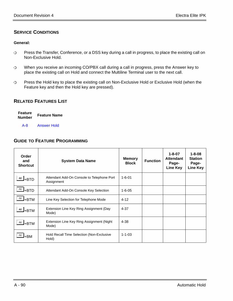
A - 90 Automatic Hold
___________________________________________________________________________________
___________________________________________________________________________________Document Revision 4 Electra Elite IPK
SERVICE CONDITIONS
General:
Press the Transfer, Conference, or a DSS key during a call in progress, to place the existing call on Non-Exclusive Hold.
When you receive an incoming CO/PBX call during a call in progress, press the Answer key to place the existing call on Hold and connect the Multiline Terminal user to the next call.
Press the Hold key to place the existing call on Non-Exclusive Hold or Exclusive Hold (when the Feature key and then the Hold key are pressed).
RELATED FEATURES LIST
GUIDE TO FEATURE PROGRAMMING
Feature Number
Feature Name
A-8 Answer Hold
Orderand
ShortcutSystem Data Name
Memory Block
Function
1-8-07Attendant
Page-Line Key
1-8-08StationPage-
Line Key
+BTD Attendant Add-On Console to Telephone Port Assignment
1-6-01
+BTD Attendant Add-On Console Key Selection 1-6-05
+BTM Line Key Selection for Telephone Mode 4-12
+BTM Extension Line Key Ring Assignment (Day Mode)
4-37
+BTM Extension Line Key Ring Assignment (Night Mode)
4-38
+BM Hold Recall Time Selection (Non-Exclusive Hold)
1-1-03
Features and Specifications Manual A - 91
___________________________________________________________________________________
___________________________________________________________________________________
Automatic Number Indication (ANI) on T1 A-23
FEATURE DESCRIPTION
T1 ANI displays the calling party telephone number on the LCD of the Multiline Terminal for incoming trunk calls. ANI information follows the call to where it is transferred.
When the MIFM-U( ) ETU with KMM(1.0)U is installed, the Caller ID information can be displayed for the last 50 incoming calls by using the Directory key or a Caller ID Scroll key when it is assigned.
Historically, ANI has been a feature of long-distance carriers typically provided on T1 circuits. The Electra Elite IPK system supports ANI on T1-FGD (Feature Group D) trunks. This feature is functionally the same as Caller ID.
ENHANCEMENTS
Release 1700:
With R1700 or higher, the following Memory Blocks are no longer needed for assigning the Caller ID or ANI features and have been removed:
1-1-78 Caller ID Display Assignment for System Mode
3-44 Caller ID Display Assignment for CO/PBX Line
4-49 Caller ID Display for CAR Key Assignment
Prior to this release, 16 stations could display Caller ID or ANI information during an incoming day or night ring assigned call. Using R1700 or higher, all stations can display Caller ID or ANI information during incoming calls.
Release 2000:
With R2000 or higher, incoming calls to SIE keys display Caller ID on a Multiline Terminal.

A - 92 Automatic Number Indication (ANI) on T1
___________________________________________________________________________________
___________________________________________________________________________________Document Revision 4 Electra Elite IPK
Release 3000:
With R3000 or higher, caller ID Scrolling is enhanced as follows:
A Class of Service option, Save Caller ID Missed Calls, has been added. When allowed, all incoming calls with Caller ID are saved in the Caller ID Scroll Log. When denied, only calls answered by the station or incoming calls never answered are saved (Same as allowed by software prior to this enhancement).
During Caller ID Scrolling, answered incoming calls display A. Incoming unanswered (missed) calls display M.
The following firmware versions are required:
With R3000 or higher, Caller ID to Single Line Telephones is supported. A Class of Service option, Send Caller ID Information to Single Line Telephones, has been added.
Version 1.54 is required for the SLIB(4)-U10/SLIE(4)-U10 ETU to support Caller ID for Single Line Telephones.
MIFM-U( ) Firmware V5.00:
MIFM-U( ) firmware V5.00 provides 50 Caller ID scroll buffers. Lower level software provided only 10 Caller ID scroll buffers.
SYSTEM AVAILABILITY
Terminal Type:
All Multiline Terminals with display
Required Components:
DTI-U( ) ETU
MIFM-U10 ETU with KMM(1.0)U installed when ANI/Caller ID Scrolling and/or Call Return are used
- OR -
MIFM-U20 ETU with KMM-U20 Upgrade Chip installed when ANI/Caller ID Scrolling and/or Call Return are used
- OR -
SPE(M)-U10 ETU
ETU Minimum Firmware Version
MIFM-U10 V6.10
MIFM-U20 V6.10
SPE(M)-U10 V6.10

Electra Elite IPK Document Revision 4
Features and Specifications Manual A - 93
___________________________________________________________________________________
___________________________________________________________________________________
OPERATING PROCEDURES
To display a stored ANI:
Press the Scroll key to display the last incoming ANI. Repeatedly press the Scroll key to display up to 50 ANI numbers.
The Scroll key is programmed using Memory Block 4-12 (Line Key Selection for Telephone Mode). Refer to the Electra Elite IPK Programming Manual for instructions.
To return a call to the number displayed on the LCD:
Go off-hook. The system automatically accesses an outside line and dials the ID number displayed on the LCD.
SERVICE CONDITIONS
General:
Caller ID indication and Automatic Number Indication (ANI) are so functionally similar that they can be assumed to have the exact same abilities and limitations.
The following incoming calls display Caller ID on a Multiline Terminal:
Ordinary CO calls
DIT/ANA calls
VRS/AA calls
Ring Transfer calls
CAR calls
SIE Calls (R2000 or higher)
ACD/UCD calls
Calls with delayed ringing
While the Multiline Terminal is ringing, the ANI Indication is displayed on the top row of the LCD.
A maximum of 13 characters can be displayed on the LCD.

A - 94 Automatic Number Indication (ANI) on T1
___________________________________________________________________________________
___________________________________________________________________________________Document Revision 4 Electra Elite IPK
Press the green line key where the CO call resides during a CO call, to verify the ANI information from any display terminal.
When the station is assigned to receive DIT/ANA calls, Caller ID is displayed only on the Multiline Terminal where DIT/ANA is assigned to ring. ANI/Caller ID follows the station Call Forward setting or Station Hunting feature.
When a Multiline Terminal is busy, the ANI/Caller ID is displayed for an incoming call.
When a Multiline Terminal is set for Do Not Disturb, the ANI/Caller ID is displayed for incoming calls.
When a Multiline Terminal receives multiple incoming calls, the first caller identification is displayed. After the first call is answered, the second caller identification is displayed.
The ANI/Caller ID disappears under the following conditions:
When an incoming call is answered.
When an internal or ring transferred call is received.
When a Feature Access, DSS, Redial, or Feature key is pressed.
The caller number is printed on the Station Message Detail Recording printout for incoming calls that are answered at stations that can display ANI/Caller ID data. The name is not printed.
When the scroll key is used, a maximum of 50 ANI/Caller IDs can be stored in System Memory. When 50 ANI/Caller IDs are stored and an additional call is received, the first ANI/Caller ID is erased from System Memory. Press the Scroll key to display the stored ANI/Caller IDs. When you go Off-hook, the displayed ANI/Caller ID is automatically dialed. The LCR feature is required for the Automatic Dial Out option.
Five users can use the Scroll function at the same time. When additional users try to scroll, IN USE is displayed at their Multiline Terminal.
ANI/Caller ID Scrolling times out and the LCD returns to idle when the Scroll key is not pressed within five seconds.
When an outgoing call is made via the Scroll function, the call follows Code Restriction, Digit Restriction, and Least Cost Routing. The LCR feature is required for the scroll function to operate properly.
ANI/Caller ID scrolling and automatic dial out features require installation of the MIFM-U( ) ETU with an attached KMM(1.0) U.
When DID conversion table is used to provide CID to the SLIB(4)-U10 ETU, the Date and Time are provided by the IPK.
When analog lines are used to provide CID to the SLIB(4)-U10 ETU, the Date and Time are provided by the CO provider.

Electra Elite IPK Document Revision 4
Features and Specifications Manual A - 95
___________________________________________________________________________________
___________________________________________________________________________________
Restrictions:
SIE incoming calls do not support Caller ID Indication even when the Multiline Terminal is ringing (R1700 or lower only).
Name is not supported on ANI trunks.
T1-ANI trunks use MF wink start signaling for incoming calls.
T1-ANI trunks use DTMF signaling for outgoing calls.
Only Feature Group D (FGD) protocol is supported.
The DTI-U( ) ETU can be installed in any Interface Slot (S1~S8) of any cabinet (1~3) without requiring vacant adjacent slots.
The available ANI service depends on the DTI-U( ) ETU version as shown in the table below.
When a system speed dial buffer is assigned number and name, the name can be displayed when the ANI number information matches a speed dial number. Memory Block 3-53 (Caller Name Indication Selection) must be assigned to TRK for the name to be displayed.
When CAR keys are assigned on the Multiline Terminal and a DIT/ANA or VRS/Automated Attendant transferred call is received at the CAR, the following assignments are required:
Use Memory Block 1-1-78 (Caller ID Display Assignment for system mode) to assign up to 15 Multiline Terminals to display ANI/Caller ID indication for normal incoming CO/PBX calls or CO/PBX calls ringing a Call Arrival (CAR) key (R1600 or below only).
Use Memory Block 4-49 (Caller ID Display for CAR Key Assignment). to assign one Multiline Terminal per CAR key to display ANI/Caller ID indication for incoming CO/PBX calls ringing on a CAR key (R1600 or below only).
Memory Block 4-37 [Extension Line Key Ring Assignment (Day Mode)] and/or Memory Block 4-38 [Extension Line Key Ring Assignment (Night Mode)].
Caller ID Name to Single Line Telephone is not supported for ISDN (BRT/PRT) Trunks.
Service DTI-U(10) ETU DTI-U(20) ETU DTI-U(30) ETU
ANI-Feature Group D Incoming only signaling
Compatible
ANI-Feature Group D Incoming MF wink start signaling and Outgoing DTMF signaling
Compatible Compatible
Key-Common Channel Interoffice Signaling (K-CCIS)
Compatible

A - 96 Automatic Number Indication (ANI) on T1
___________________________________________________________________________________
___________________________________________________________________________________Document Revision 4 Electra Elite IPK
RELATED FEATURES LIST
GUIDE TO FEATURE PROGRAMMING
Feature Number
Feature Name
C-5 Caller ID Indication (Analog Trunks)
I-9 ISDN-BRI Trunk Connections
I-10 ISDN-PRI Trunk Connections
L-3 Least Cost Routing (LCR)
S-7 Single Line Telephone Access
T-1 T1 Connection
Orderand
ShortcutSystem Data Name
Memory Block
Function
1-8-07Attendant
Page-Line Key
1-8-08StationPage-
Line Key
+BS Card Interface Slot Assignment 7-1
+BS MIF (ANI/Caller ID) Assignment 7-3-04
+AD Signal Format Selection 1-11-00
+AD Clear Channel Selection 1-11-01
+AD Line Length Selection 1-11-02
+AD IP K-CCIS Selection 1-11-03
+AD T1 Channel Selection 1-11-05
+AD Signaling Selection 1-11-06
+AD DTI Trunk Type Assignment 1-11-07
+AD Digits Delete for T1 ANI Assignment 1-11-08
+AD Master Clock Selection 1-8-33
+AI Caller ID Display Assignment for System Mode (R1600 or lower)
1-1-78
+BTS Class of Service (Station) Feature Selection 2
1-8-08 4-3, 4-4,5-7, 6-5, 7-1

Electra Elite IPK Document Revision 4
Features and Specifications Manual A - 97
___________________________________________________________________________________
___________________________________________________________________________________
+BTTStation to Class of Service Feature Assignment
4-17
+AI Caller Name Indication Selection 3-53
+BCT Trunk-to-Trunk Group Assignment 3-03
+AICaller ID Display Assignment for CO/PBX Line (R1600 or lower)
3-44
+AI Caller ID Outgoing CO Selection 4-44
+BTM Line Key Selection for Telephone Mode 4-12
+BTMExtension Line Key Ring Assignment (Day Mode)
4-37
+BTMExtension Line Key Ring Assignment (Night Mode)
4-38
+BTM SIE/CAR Ringing Line Preference Selection 4-41
+AICaller ID Display for CAR Key Assignment(R1600 or lower)
4-49
When the system is at default this Memory Block must be programmed for the feature to be used.
Orderand
ShortcutSystem Data Name
Memory Block
Function
1-8-07Attendant
Page-Line Key
1-8-08StationPage-
Line Key

A - 98 Automatic Number Indication (ANI) on T1
___________________________________________________________________________________
___________________________________________________________________________________Document Revision 4 Electra Elite IPK
THIS PAGE INTENTIONALLY LEFT BLANK
Features and Specifications Manual A - 99
___________________________________________________________________________________
___________________________________________________________________________________
Automatic Redial A-24
FEATURE DESCRIPTION
Automatic Redial simplifies repetitive dialing to a busy or unanswered outgoing call. After a busy tone or no answer is received during a CO/PBX call, the system systematically redials the party number while the station user monitors the call for completion.
SYSTEM AVAILABILITY
Terminal Type:
All Multiline Terminals
Required Components:
None
OPERATING PROCEDURES
To set while receiving a busy tone or no answer on an outside call:
1. When using the handset, press E , and restore the handset.
2. Press A .
3. Press B .
4. The call is repeated automatically (default: 2 times).
5. Lift the handset to respond when the called party answers. When this is not done, the call is disconnected when the next redial cycle starts.

A - 100 Automatic Redial
___________________________________________________________________________________
___________________________________________________________________________________Document Revision 4 Electra Elite IPK
To cancel Automatic Redial:
Lift the handset, then restore handset, or press E .
- OR -
Automatic Redial is canceled automatically when the specified number of redials (default: 2) is completed.
SERVICE CONDITIONS
General:
This feature remains in effect until the party initiating the call lifts and restores the handset or presses Speaker during a redial attempt. An incoming call is answered on that line, or two (default) redial attempts are made.
The system does not detect answer, no answer, or busy condition from the outside network.
When Automatic Redial is in progress (a call is being initiated by the system), an LCD appearance (: Number Dialed) confirms Automatic Redial is activated. For stations with or without an LCD, a flashing Feature LED indication is provided, and the Redial key is on continuously.
The outside line LED on the Multiline Terminal, where Automatic Redial is initiated, is green but on other Multiline Terminals in the system it is red.
When the feature times out, access a CO/PBX line, press the Feature key and then the Redial key, or a Feature Access or One-Touch key programmed to activate this feature.
When an incoming CO/PBX call is received from the CO during the waiting period of the Automatic Redial feature, Automatic Redial is released, and a busy tone is sent to the station.
The handset must be lifted off-hook to disable Automatic Redial after an outside call is answered.
Use Memory Block 1-1-04 (Automatic Redial Time Selection) to program Automatic Redial Time parameters as follows:
ProgrammingRange
Default
Callback Time: 1~50 seconds 030
Wait Time: 1~100 seconds 060
Redial Times: 1~ 15 times 002

Electra Elite IPK Document Revision 4
Features and Specifications Manual A - 101
___________________________________________________________________________________
___________________________________________________________________________________
Restrictions:
The station retains sole use of the outside line during Automatic Redial.
An internal call received during Automatic Redial cannot be answered unless Automatic Redial is released. The calling station receives a call waiting tone.
A station user cannot set a Tone Override to a station with an Automatic Redial set. However, a Callback Request or an Automatic Callback can be set.
This feature is not available for Single Line Telephones.
This feature is not available for Tie/DID lines.
GUIDE TO FEATURE PROGRAMMING
Orderand
ShortcutSystem Data Name
Memory Block
Function
1-8-07Attendant
Page-Line Key
1-8-08StationPage-
Line Key
+BM Automatic Redial Time Selection 1-1-04
+BTS Manual Pause Selection 1-1-09

A - 102 Automatic Redial
___________________________________________________________________________________
___________________________________________________________________________________Document Revision 4 Electra Elite IPK
THIS PAGE INTENTIONALLY LEFT BLANK

Features and Specifications Manual A - 103
___________________________________________________________________________________
___________________________________________________________________________________
Automatic Release A-25
FEATURE DESCRIPTION
Automatic Release drops the line circuit when an outside party abandons the call. For this feature to work with Loop Start Trunks, the CO/PBX providing the outside line must provide a timed disconnect signal. Automatic release is normally provided on Ground Start, DID, ISDN, and Tie Line Trunks.
SYSTEM AVAILABILITY
Terminal Type:
Not applicable
Required Components:
None
OPERATING PROCEDURES
None
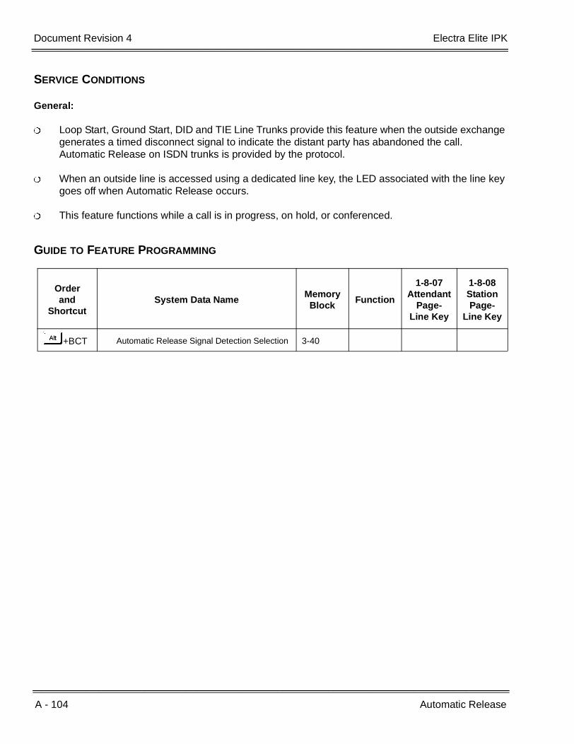
A - 104 Automatic Release
___________________________________________________________________________________
___________________________________________________________________________________Document Revision 4 Electra Elite IPK
SERVICE CONDITIONS
General:
Loop Start, Ground Start, DID and TIE Line Trunks provide this feature when the outside exchange generates a timed disconnect signal to indicate the distant party has abandoned the call. Automatic Release on ISDN trunks is provided by the protocol.
When an outside line is accessed using a dedicated line key, the LED associated with the line key goes off when Automatic Release occurs.
This feature functions while a call is in progress, on hold, or conferenced.
GUIDE TO FEATURE PROGRAMMING
Orderand
ShortcutSystem Data Name
Memory Block
Function
1-8-07Attendant
Page-Line Key
1-8-08StationPage-
Line Key
+BCT Automatic Release Signal Detection Selection 3-40

Features and Specifications Manual A - 105
___________________________________________________________________________________
___________________________________________________________________________________
Automatic Route Selection (ARS) A-26
FEATURE DESCRIPTION
Automatic Route Selection (ARS) allows an outgoing line to be seized using a Trunk Group or Route Advance Block (RAB) for each number dialed by the user. The ARS feature allows more efficient use of the trunks connected to the system.
SYSTEM AVAILABILITY
Terminal Type:
All Multiline Terminals
Required Components:
None
OPERATING PROCEDURES
To use this feature:
1. Lift the handset, and wait for dial tone.
2. Dial ARS access codeI(default) and receive LCR dial tone.
3. Dial the desired number.
A - 106 Automatic Route Selection (ARS)
___________________________________________________________________________________
___________________________________________________________________________________Document Revision 4 Electra Elite IPK
SERVICE CONDITIONS
General:
All Trunk Groups in the system (00 is used to deselect trunk groups) can be accessed using ARS.
Trunk Group Access code 9 (default) activates ARS at stations assigned for LCR Class assignment using Memory Block 4-40 (LCR Class Selection).
ARS is based on actual digits dialed to properly route the call.
ARS can be programmed to consider a maximum of eight dialed digits before making a selection for the number dialed.
When using Code Restriction with ARS, code restriction applies to the digits dialed by the system.
After a 10 second interdigit time expires during dialing using ARS, a busy tone is generated, and the user must redial the number.
When a station user places an outgoing call using ARS, Trunk queuing cannot be set.
When a feature code is assigned to CO Feature Service code for Code Restriction using Memory Block 1-1-82 (CO Feature Code Service for Code Restriction), this code does not have to be programmed in the ARS Dialing Assignment Tables.
When ARS route assignment 00 is set using Memory Block 1-14-03 (ARS Route Table Number Assignment), the dialed number is sent out Trunk Group 01 the way the number was dialed.
Memory Block 1-8-08 (Class of Service (Station) Feature Selection 2), ARS Overflow (Page 6, LK1) allows or restricts access to Trunk Group 01 when first priority Trunk Group (programmed route) is busy.
Use Memory Block 1-1-46~48 [Access Code (1-, 2-, or 3-Digit) Assignment] (Function No. 101) to assign an access code.
Restrictions
Route Advance Blocks or Trunks programmed on a line key, bypass ARS.
Memory Block 1-8-08 (Class of Service (Station) Feature Selection 2), LCR/ARS Bypass only applies when the station is assigned to a LCR/ARS Class (1~4) in Memory Block 4-40 (LCR Class Selection). ARS Bypass does not apply when using access codes to directly access an ARS Table (functions 601~604 - ARS Tables 1~4) in Memory Blocks 1-1-46~48 (Access Code (1-, 2-, 3-Digit Assignment).
ARS is not available when the Electra Elite 48/192 system is in KF registration.
Outgoing calls using Direct Inward System Access (DISA) cannot access ARS.

Electra Elite IPK Document Revision 4
Features and Specifications Manual A - 107
___________________________________________________________________________________
___________________________________________________________________________________
ARS cannot be used to route calls by hour of day or day of week.
Only a single Route Assignment can be specified for each Dialing Assignment entry.
When ARS is set to YES (allow) using Memory Block 1-14-00 (ARS Allow/Deny Selection), the MIFM LCR is disabled even when allowed in system programming.
A maximum of 10 digits can be deleted or added to a Route Assignment.
GUIDE TO FEATURE PROGRAMMING
Orderand
ShortcutSystem Data Name
Memory Block
Function
1-8-07Attendant
Page-Line Key
1-8-08StationPage-
Line Key
+BAAccess Code (1-, 2-, 3-Digit) Assignment 1-1-46/47/
48
+BCT Trunk-to-Trunk Group Assignment 3-03
+BCT Trunk Type Selection 3-91
+BTT LCR Class Selection 4-40
+BTS Class of Service (Station) Feature Selection 2
1-8-08 3-4, 6-1
+BTTStation to Class of Service Feature Assignment
4-17
+BTM Line Key Selection for Telephone Mode 4-12
+AB ARS Allow/Deny Selection 1-14-00
+AB ARS Dialing Assignment 1-14-01
+AB ARS Dial Allow/Deny Selection 1-14-02
+AB ARS Route Table Number Assignment 1-14-03
+AB ARS Trunk Group to Route Number Assignment
1-14-04
+AB ARS Digit Delete Assignment 1-14-05
+AB ARS Digit Add Assignment 1-14-06
When the system is at default this Memory Block must be programmed for the feature to be used.
A - 108 Automatic Route Selection (ARS)
___________________________________________________________________________________
___________________________________________________________________________________Document Revision 4 Electra Elite IPK
THIS PAGE INTENTIONALLY LEFT BLANK
Features and Specifications Manual A - 109
___________________________________________________________________________________
___________________________________________________________________________________
Automatic Trunk-to-Trunk Transfer A-27
FEATURE DESCRIPTION
Automatic Trunk-to-Trunk Transfer allows an incoming CO/PBX call to be automatically dialed out of the system over another outside line to a programmed telephone number. This is especially useful for forwarding calls to an answering service during nonbusiness hours (i.e., nights, weekends, or holidays).
SYSTEM AVAILABILITY
Terminal Type:
Assigned Attendant Position Multiline Terminals with this ability.
Required Components:
None
OPERATING PROCEDURES
To set the Trunk Forward Assignment from the Attendant Position:
1. Press A .
2. DialFC.
3. Dial the incoming trunk number (KA~FD).
4. PressL.
5. Dial outgoing telephone number where the call is to be directed.
6. Press A .

A - 110 Automatic Trunk-to-Trunk Transfer
___________________________________________________________________________________
___________________________________________________________________________________Document Revision 4 Electra Elite IPK
To cancel the Trunk Forward Assignment from the Attendant Position:
1. Press A .
2. DialFC.
3. Dial the incoming trunk number (KA~FD).
4. PressL.
5. Press A .
To set the Automatic Trunk-to-Trunk Transfer Mode from the Attendant Position:
1. Press A .
2. Dial FA.
3. Dial the incoming trunk number (KA~FD).
4. Press A .
Dialing 00 sets the Automated Attendant mode for all trunks when the trunks are idle. When 00 is dialed, a busy trunk is not set. To set the Automated Attendant to a busy trunk, dial the individual trunk number.
To cancel the Automatic Trunk-to-Trunk Transfer Mode from the Attendant Position:
1. Press A .
2. Dial FB.
3. Dial the incoming trunk number (KA~FD).
4. Press A .
Dial 00 to cancel the Automatic Trunk-to-Trunk Mode for all trunks when the trunks are idle. When 00 is dialed, a busy trunk is not canceled. To cancel Automated Trunk-to-Trunk mode to a busy trunk, dial the individual trunk number.
To confirm the Trunk Forward Assignment from the Multiline Terminals with LCD:
1. Press A .
2. Dial FD.

Electra Elite IPK Document Revision 4
Features and Specifications Manual A - 111
___________________________________________________________________________________
___________________________________________________________________________________
3. Dial the incoming trunk number (KA~FD).
4. Press A (outgoing telephone number is displayed in the LCD). When the outgoing telephone number is longer than nine digits, continue to press A to display each remaining digit.
SERVICE CONDITIONS
General:
When this feature is activated, and an incoming call rings in, any ringing assigned station rings and the call can be answered while the outgoing call is being made.
The incoming or outgoing trunk can be a CO/PBX or Tie/DID line.
The Attendant can press the Feature key and the line key to verify the Automatic Trunk-to-Trunk Transfer status when set.
When the outgoing line is in use and an incoming call rings in, the call is treated as a normal incoming call. When the outgoing line becomes free, the Automatic Trunk-to-Trunk Transfer feature is activated.
When this feature is activated, the incoming trunk LEDs assigned on Multiline Terminals wink and the outgoing trunk LEDs are always On.
When this feature is activated, the winking incoming trunks set for Automatic Trunk-to-Trunk Transfer are available for outgoing use.
The outgoing telephone number cannot exceed 24 digits.
After the system dials the outgoing number, the incoming call is transferred, the trunk LED assigned to Line keys is On steady, and the call cannot be answered.
Restrictions:
Outgoing trunks cannot be used when this feature is set.
Automatic Trunk-to-Trunk Transfer and Automated Attendant cannot be set for the same trunk at the same time.
Only trunks assigned in Memory Block 3-05 (Trunk Incoming Answer Mode Selection) for TANDM TRF are set or canceled for Automatic Trunk-to-Trunk Transfer Mode when an Attendant Position enters 00 during set or cancel operation.

A - 112 Automatic Trunk-to-Trunk Transfer
___________________________________________________________________________________
___________________________________________________________________________________Document Revision 4 Electra Elite IPK
GUIDE TO FEATURE PROGRAMMING
Orderand
ShortcutSystem Data Name
Memory Block
Function
1-8-07Attendant
Page-Line Key
1-8-08StationPage-
Line Key
+BCT Trunk Incoming Answer Mode Selection 3-05
+AT Automatic Tandem Trunk Assignment 3-06
+BCT Trunk-to-Trunk Transfer Yes/No Selection 3-04
+BTS Class of Service (Attendant) Feature Selection 1
1-8-07 1-7
+BTTStation to Class of Service Feature Assignment
4-17
+ATAutomatic Tandem Trunk by Night Mode Selection
1-4-05
+ATTandem Transfer Automatic Disconnect Time Selection
1-4-00
+BCT Automatic Release Signal Detection Selection 3-40
When the system is at default this Memory Block must be programmed for the feature to be used.

Features and Specifications Manual B - 1
___________________________________________________________________________________
___________________________________________________________________________________
Background Music Over External
Speakers B-1
FEATURE DESCRIPTION
Background music over external speakers is integrated with the three-zone paging system provided by the ECR-U( ) ETU. The connection does not require an external relay system. When a zone (or all zones) is connected to paging, the paging system BGM is turned off automatically.
SYSTEM AVAILABILITY
Terminal Type:
Not applicable
Required Components:
ECR-U( ) ETU
OPERATING PROCEDURES
None
SERVICE CONDITIONS
General:
No amplifier is provided on the ECR-U( ) ETU.
The impedance of the speakers must be 600 Ω.
The Paging BGM input impedance is 600 Ω.
The control relays can handle up to 24 Vdc @ 500 mA.
The paging output comes from the ECR-U( ) ETU to an amplifier (up to 10W) and then back into the ECR-U( ) ETU. The speakers are connected to the ECR-U( ) ETU (up to three zones). The ECR-U( ) ETU does the rest.

B - 2 Background Music Over External Speakers
___________________________________________________________________________________
___________________________________________________________________________________Document Revision 4 Electra Elite IPK
GUIDE TO FEATURE PROGRAMMING
Orderand
ShortcutSystem Data Name
Memory Block
Function
1-8-07Attendant
Page-Line Key
1-8-08StationPage-
Line Key
+BS Card Interface Slot Assignment 7-1
+BP General Purpose Relay Assignment 1-8-37
+BP External Speaker Connection Selection 1-7-02
+BP External Paging Alert Tone Selection 1-7-03
+BP External Paging Timeout Selection 1-7-06
Features and Specifications Manual B - 3
___________________________________________________________________________________
___________________________________________________________________________________
Background Music – Multiline Speaker B-2
FEATURE DESCRIPTION
Music on hold provides station background music through the station speaker when the station is idle. A loop-start COI port can be used as an alternate background music source when a Valcom V-9941A unit, or equivalent, is provided.
SYSTEM AVAILABILITY
Terminal Type:
All Multiline Terminals
Required Components
None
OPERATING PROCEDURES
To set Background Music (BGM) when the Multiline Terminal is idle:
1. Press BGM On/Off key (or press A BF).
2. Background Music is displayed on the Multiline Terminals for five seconds.
To cancel Background Music:
1. Press BGM On/Off key (or press A BF).
2. The Background Music display is canceled after five seconds.
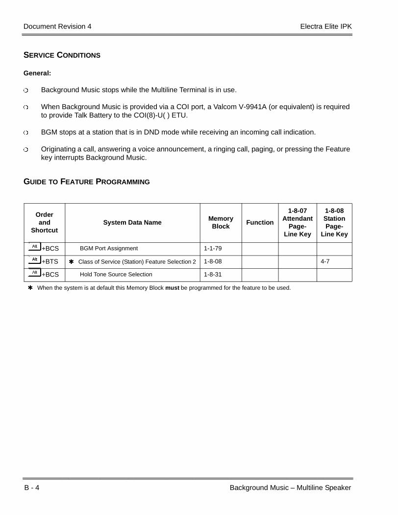
B - 4 Background Music – Multiline Speaker
___________________________________________________________________________________
___________________________________________________________________________________Document Revision 4 Electra Elite IPK
SERVICE CONDITIONS
General:
Background Music stops while the Multiline Terminal is in use.
When Background Music is provided via a COI port, a Valcom V-9941A (or equivalent) is required to provide Talk Battery to the COI(8)-U( ) ETU.
BGM stops at a station that is in DND mode while receiving an incoming call indication.
Originating a call, answering a voice announcement, a ringing call, paging, or pressing the Feature key interrupts Background Music.
GUIDE TO FEATURE PROGRAMMING
Orderand
ShortcutSystem Data Name
Memory Block
Function
1-8-07Attendant
Page-Line Key
1-8-08StationPage-
Line Key
+BCS BGM Port Assignment 1-1-79
+BTS Class of Service (Station) Feature Selection 2 1-8-08 4-7
+BCS Hold Tone Source Selection 1-8-31
When the system is at default this Memory Block must be programmed for the feature to be used.
Features and Specifications Manual B - 5
___________________________________________________________________________________
___________________________________________________________________________________
Barge-In B-3
FEATURE DESCRIPTION
Barge-In allows selected Multiline Terminal users in the system to override another station user conversation with or without an audible alert to that station user. The alert tone is programmable.
ENHANCEMENTS
Release 1700
With Release R1.70 or higher, Memory Block 1-1-76 (Barge-In Alert Tone Assignment) controls the Conf LED at the station barged into as follows:
YS (Allow) The Conf LED is On.
NO (Denied) The Conf LED is Off.
Prior to this release, the Conf LED was always on at the station that was barged into.
SYSTEM AVAILABILITY
Terminal Type:
All Multiline Terminals
Required Components:
None
Monitoring telephone conversations may be illegal under certain circumstances and laws. Consult a legal advisor before implementing the monitor of conversations. Some federal and state laws require a monitoring party to use an alert tone to indicate monitoring and/or obtain consent from all parties to the conversation. Some laws provide strict penalties for illegal monitoring of telephone conversations.

B - 6 Barge-In
___________________________________________________________________________________
___________________________________________________________________________________Document Revision 4 Electra Elite IPK
OPERATING PROCEDURES
To Barge-in using a station number:
1. Lift the handset or press E , and wait for internal dial tone.
2. Press A , then press D .
3. Dial the station number to be overridden.
4. Press A .
5. Interrupt is enabled.
To Barge-in using an outside line number:
1. Lift the handset or press E and wait for internal dial tone.
2. Press A , then press D .
3. Dial J.
4. Dial the CO/PBX number to be overridden.
5. Press A .
6. Interrupt is enabled.
To Barge-in using an outside line key:
1. Lift the handset or press E , and wait for internal dial tone.
2. Press A , then press D .
3. Press the CO/PBX line key to be interrupted.
4. Interrupt is enabled.
SERVICE CONDITIONS
General:
Multiline Terminals can be used to interrupt the privacy of conversations on outside lines.

Electra Elite IPK Document Revision 4
Features and Specifications Manual B - 7
___________________________________________________________________________________
___________________________________________________________________________________
Barge-In overrides a conversation held by a station in Do Not Disturb mode.
When Barge-In is denied, DENIED is displayed in the LCD.
The station interrupting an outside line cannot put the CO/PBX call on hold.
Each Barge-In in progress uses a conference circuit.
When Memory Block 1-1-76 (Barge-In Alert Tone Assignment) is assigned YS (Allow), both the internal and external parties receive the tone.
When a call with Barge-In in progress is placed on hold, the held status is displayed on the Conference LED (Conf LED flashes), and the green CO or CAP key line appearance turns red. To retrieve the held call, press the flashing COnf key. This condition is valid for all software releases.
Restrictions:
Barge-In is not allowed for internal calls.
Barge-In is not allowed until the Elapsed Call Time starts.
Add-On Conference calls cannot be interrupted.
The Barge-In feature is not permitted when all 16 Add-On Conferences are in progress.
The Barge-In feature does not override conversation on a Private Line.
A Single Line Telephone user cannot activate Barge-In; however, the conversation on a Single Line Telephone can be interrupted.
The Barge-In feature cannot be used on outside lines for another tenant unless the lines are assigned to both tenants.
Data Line Security prevents a station from being barged in on, even when Barge-In is allowed in Class of Service.
Barge-In is not allowed on outside lines on Hold.

B - 8 Barge-In
___________________________________________________________________________________
___________________________________________________________________________________Document Revision 4 Electra Elite IPK
RELATED FEATURES LIST
GUIDE TO FEATURE PROGRAMMING
Feature Number
Feature Name
C-19 Class of Service
D-1 Data Line Security
E-1 Elapsed Call Time
P-8 Private Lines
T-3 Tenant Service
Orderand
ShortcutSystem Data Name
Memory Block
Function
1-8-07Attendant
Page-Line Key
1-8-08StationPage-
Line Key
+BTS Class of Service (Station) Feature Selection 2 1-8-08 1-4, 1-5
+BTTStation to Class of Service Feature Assignment
4-17
+BN Trunk to Tenant Assignment 2-01
+BCS Private Line Assignment 1-1-29
+BTT SLT Data Line Security Assignment 4-90
+BTS Barge-In Alert Tone Assignment 1-1-76
+BM Start time Selection 1-1-05
When the system is at default this Memory Block must be programmed for the feature to be used.
Features and Specifications Manual B - 9
___________________________________________________________________________________
___________________________________________________________________________________
Battery Backup – System Memory B-4
FEATURE DESCRIPTION
A battery is provided on the CPUI( )-U( ) ETU for the Electra Elite IPK system to retain System Program Memory when power fails. When fully charged, the battery maintains backup power for approximately 21 days. System Data, Speed Dial Memories, and Clock/Calendar functions are protected by the backup battery. After power is restored, the system returns to normal operation.
SYSTEM AVAILABILITY
Terminal Type:
Not applicable
Required Components:
None
OPERATING PROCEDURES
None

B - 10 Battery Backup – System Memory
___________________________________________________________________________________
___________________________________________________________________________________Document Revision 4 Electra Elite IPK
SERVICE CONDITIONS
General:
The battery connector on the CPUI( )-U( ) ETU should be disconnected during long term storage but must be connected (protection against loss of power) just before installation to provide battery backup for System Memory.
When fully charged, the battery retains System Memory for approximately 21 days.
Battery backup on the CPUI( )-U( ) ETU retains memory for the following functions:
System Program
Night Transfer Status
Call Forwarding
Callback Request
Speed Dial Memories (System/Station)
Clock/Calendar
Do Not Disturb (DND)
Save and Repeat
Store and Repeat
Last Number Redial
Message Waiting
Microphone Status
Station Lock (Set and Password)
Timed Alarm
Customized Message
Voice Mail Message
Feature Access and One-Touch Keys
Volume Set Level
Automatic Attendant Mode
Automatic Trunk-to-Trunk Transfer Mode
General Purpose Relay Setting
Electra Elite IPK Document Revision 4
Features and Specifications Manual B - 11
___________________________________________________________________________________
___________________________________________________________________________________
During normal operation, the batteries are continually recharged using a built-in charging circuit.
Restrictions:
Battery backup on the CPUI( )-U( ) ETU does not protect the following:
Automatic Callback
Off-line Status (for programming system or station assignments)
Automatic Redial
Trunk Queuing
RELATED FEATURES LIST
Feature Number
Feature Name
B-4 Battery Backup – System Power

B - 12 Battery Backup – System Memory
___________________________________________________________________________________
___________________________________________________________________________________Document Revision 4 Electra Elite IPK
THIS PAGE INTENTIONALLY LEFT BLANK
Features and Specifications Manual B - 13
___________________________________________________________________________________
___________________________________________________________________________________
Battery Backup – System Power B-5
FEATURE DESCRIPTION
A built-in battery provides complete system operating power for approximately 30 minutes during commercial power outages. When optional (locally provided) batteries are connected and fully charged, full system operation can be maintained for an extended time. Actual time depends on system configuration, traffic conditions, and the capacity of the batteries.
SYSTEM AVAILABILITY
Terminal Type:
Not applicable
Required Components:
B64-U( ) KSU
OPERATING PROCEDURES
None
SERVICE CONDITIONS
General:
During normal operation, the batteries are continually recharged by a built-in charging circuit.
The B64-U( ) KSU is equipped with batteries for system battery backup.

B - 14 Battery Backup – System Power
___________________________________________________________________________________
___________________________________________________________________________________Document Revision 4 Electra Elite IPK
RELATED FEATURES LIST
Feature Number
Feature Name
B-4 Battery Backup – System Memory

Features and Specifications Manual B - 15
___________________________________________________________________________________
___________________________________________________________________________________
Busy Lamp Field on Multiline Terminals B-6
FEATURE DESCRIPTION
The Busy Lamp Field (BLF) indicates station status using LEDs. The applicable LED is on for Feature Access keys and One-Touch keys that are programmed for Direct Station Selection (DSS). This allows Multiline Terminal users to determine at a glance that a station is in use.
SYSTEM AVAILABILITY
Terminal Type:
DTU/DTP or DTH/DTR-8-1 TEL Up to eight line keys
DTU-8D-1 or DTP/DTH/DTR-8D-2 TEL Up to eight line keys
DTU/DTP-16-1 TEL Up to 16 line keys
DTU-16D-1 or DTP/DTH/DTR-16D-2 TEL Up to 16 line keys
DTU-16HC-1 TEL Up to 16 line keys
DTH-16LD-1 TEL Up to 16 line keys
DTU/DTP-32-1 TEL Up to 16 line keys and 16 One-Touch keys
DTU-32D-1 or DTP/DTH/DTR-32D-2 TEL Up to 16 line keys and 16 One-Touch keys
The 16 LD telephone indicates BLF status by an LED indicator.
Required Components:
None

B - 16 Busy Lamp Field on Multiline Terminals
___________________________________________________________________________________
___________________________________________________________________________________Document Revision 4 Electra Elite IPK
OPERATING PROCEDURES
To program the Feature Access key for DSS/BLF:
1. Press A .
2. Press B .
3. Press the Feature Access key.
4. Dial A.
5. Dial the station number.
6. Dial A (optional step, toggles call between voice and tone).
7. Press A .
To program the One-Touch key for DSS/BLF:
1. Press A .
2. Press B .
3. Press the One-Touch key.
4. Dial A.
5. Dial the station number.
6. Dial A (optional step, toggles call between voice and tone).
7. Press A .

Electra Elite IPK Document Revision 4
Features and Specifications Manual B - 17
___________________________________________________________________________________
___________________________________________________________________________________
SERVICE CONDITIONS
General:
A single color LED (red only) is used to indicate the following station status:
Local power is not required for the BLF function on a Multiline Terminal. The Attendant Add-On Console requires an AC transformer that is provided with the console.
Assignment of One-Touch keys for Direct Station Selection (DSS) with busy lamp indications is programmable by the user from the Multiline Terminal. Any existing station can be assigned.
GUIDE TO FEATURE PROGRAMMING
LED is Flashing: Station is in Do Not Disturb (DND) or Call Forward – All Call, Break Mode.
LED is Winking: Station is Off-Line (to program). Station is accessing Feature functions.
LED On: Station is busy, receiving Voice Announcement, receiving Internal/DIT/ANA/TIE/DID ringing signal, or was put on hold.
LED Off: Station is idle, receiving CO/PB call, receiving CO/PBX transferred call, or receiving recall.
Orderand
ShortcutSystem Data Name
Memory Block
Function
1-8-07Attendant
Page-Line Key
1-8-08StationPage-
Line Key
+BE Speed Dial Buffer Allocation 1-1-35
+BTM Line Key Selection for Telephone Mode 4-12

B - 18 Busy Lamp Field on Multiline Terminals
___________________________________________________________________________________
___________________________________________________________________________________Document Revision 4 Electra Elite IPK
THIS PAGE INTENTIONALLY LEFT BLANK

Features and Specifications Manual C - 1
___________________________________________________________________________________
___________________________________________________________________________________
Call Alert Notification C-1
FEATURE DESCRIPTION
Call Alert Notification allows a station user to receive an alert tone, flashing ICM, Large LED, and LCD identification during an incoming call while the user station is busy. This allows the station user to put the current call on hold to answer a second call to increase call handling abilities.
This feature works with Call Forward – Busy/No Answer so the second incoming call is queued to the station for eight seconds (default) before it is forwarded.
SYSTEM AVAILABILITY
Terminal Type:
All Stations
Required Components:
None
OPERATING PROCEDURES
To answer an incoming DIT, DID, Tie line, or Automated Attendant transferred call on a Multiline Terminal, after receiving a Call Alert Notification while talking with another party:
1. Press H . The first call is put on hold.
2. Incoming caller is automatically connected.
C - 2 Call Alert Notification
___________________________________________________________________________________
___________________________________________________________________________________Document Revision 4 Electra Elite IPK
To answer the incoming call on any station (single-line station in particular), after receiving a Call Alert Notification while talking with another party:
1. Go on-hook on the first call.
2. Go off-hook to answer the incoming call.
SERVICE CONDITIONS
General:
This feature is provided for DID, DIT, Tie line, internal transferred calls, and Automated Attendant transferred calls.
When an Automated Attendant transferred call does not get answered and changes to a normal CO ringing, the Call Alert Notification is no longer provided at the station receiving the transferred call.
When a station that has Call Forward – No Answer assigned receives a second call, it follows the Call Forward – No Answer time before it is forwarded.
When a station is already receiving a Call Alert Notification, an additional internal call to this station provides Busy tone to the caller. When Call Forward – Busy is set, the internal call follows this forward setting.
Incoming Call Alert Notification to Multiline Terminals is as follows:
ICM and Large LED flash.
LCD shows second incoming call.
A Call Alert Notification tone of 0.8 seconds is provided to the called party.
The LCD does not indicate that a second call is ringing in when using Store and Repeat.
During Incoming Call Alert Notification to a Single Line Telephone, a Call Alert Notification tone of 0.8 seconds is provided to the called party.
The calling party hears the following when the called station is already on another call:
Automated Attendant, DIT, DID, and Tie line callers hear ringback tone.
Internal callers hear call waiting, allowing Step Calling to be used.
When a station is the Master Hunt Number for a Station Hunt group, the second call follows the Station Hunt Group assignment. When all agents in this group are busy, Call Alert Notification is given to the called party and the call remains at the master station.

Electra Elite IPK Document Revision 4
Features and Specifications Manual C - 3
___________________________________________________________________________________
___________________________________________________________________________________
Multiple incoming calls, except internal and Automated Attendant transferred calls, continue to ring at a busy station. However, the LCD of this station indicates only the first call waiting to be answered.
ACD agents that are busy on a call do not receive Call Alert Notification when another ACD call is received. Call Alert Notification is provided when a call is transferred to the station and not the pilot.
The following maximum incoming calls can wait at a station:
DIT, DID, and Tie lines:No Limitation.
Internal and Automated Attendant transferred calls:No Limitation.
When a station with Call Forward – Busy assigned receives a second call, this call follows the Call Forward – Busy setting either immediately or after the Call Forward – No Answer time has expired.
When Memory Block 1-8-08 (Class of Service (Station) Feature Selection 2, Page 3 LK8 (Call Alert Notification) is set for deny, incoming Tie Line or DID calls to a busy station are restricted and the calling party receives a busy tone. This assignment is not used to restrict an incoming DIT call to a busy station and does not block the Call Alert tone to the user.
When Memory Block 1-8-08 (Class of Service (Station) Feature Selection 2, Page 3 LK3 (Voice/Tone Override [Receive]) is set for deny, the Call Alert tone is not provided to the speaker of the Multiline Terminal or to the handset.
When Memory Block 4-90 (SLT Data Line Security Assignment) is assigned for a Multiline Terminal, incoming Tie Line, DID, or DIT calls to the busy terminal produce a call Alert tone only through the speaker of the Multiline Terminal. The Call Alert tone cannot be heard form the handset.
Use Memory Block 4-42 (Call Forward – Busy Immediately/Delay Selection) to specify immediate forward (NO) or delay forward (default: YS) for an incoming call when the station is set for Call Forward – Busy.
Restrictions:
When a station that has set DND receives a second call, Call Alert Notification tone is not provided.
A station does not receive Call Alert Notification when Automatic Redial is activated.
Call Alert Notification calls cannot be answered using Call Pickup.
Call Forwarding can be set or canceled only when logged out of ACD.
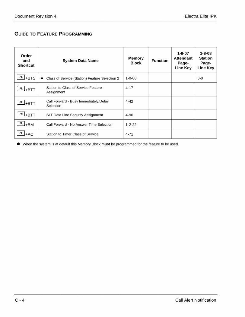
C - 4 Call Alert Notification
___________________________________________________________________________________
___________________________________________________________________________________Document Revision 4 Electra Elite IPK
GUIDE TO FEATURE PROGRAMMING
Orderand
ShortcutSystem Data Name
Memory Block
Function
1-8-07Attendant
Page-Line Key
1-8-08StationPage-
Line Key
+BTS Class of Service (Station) Feature Selection 2 1-8-08 3-8
+BTTStation to Class of Service Feature Assignment
4-17
+BTTCall Forward - Busy Immediately/Delay Selection
4-42
+BTT SLT Data Line Security Assignment 4-90
+BM Call Forward - No Answer Time Selection 1-2-22
+AC Station to Timer Class of Service 4-71
When the system is at default this Memory Block must be programmed for the feature to be used.
Features and Specifications Manual C - 5
___________________________________________________________________________________
___________________________________________________________________________________
Call Appearance (CAP) Keys C-2
FEATURE DESCRIPTION
This feature automatically places an outside call on a Call Appearance key when the system is operated as a hybrid (Multifunction) system. These keys can be assigned on any Multiline Terminal or the same key can appear on multiple terminals. This feature allows efficient call handling when numerous CO calls are received and a limited number of CO line key appearances are available. These keys are often called CO loop keys.
SYSTEM AVAILABILITY
Terminal Type:
All Multiline Terminals
Required Components:
None
OPERATING PROCEDURES
To place a Multiline Terminal outgoing call on hold and retrieve it:
1. Go off-hook using the handset or press E . Wait for internal dial tone.
2. Dial Trunk Access Code (default:I). A Call Appearance key lights.
3. Dial the outside party, and begin conversation.
4. Press H . The Call Appearance key flashes.
5. Press the flashing Call Appearance key to retrieve the call.

C - 6 Call Appearance (CAP) Keys
___________________________________________________________________________________
___________________________________________________________________________________Document Revision 4 Electra Elite IPK
To place a Multiline Terminal incoming call on hold and retrieve it:
1. Receive CO/PBX incoming ring.
2. Go off-hook using the handset, or press E . A Call Appearance key lights. Talk with outside party.
3. Press H . The Call Appearance key flashes.
4. Press the flashing Call Appearance key to retrieve the call.
SERVICE CONDITIONS
A trunk call that is originated or answered at a Multiline Terminal must appear on a line key. The line key can be assigned as the trunk or as a Call Appearance Key. A CAP is dynamic because it is used for any trunk call. An 8-key multiline terminal can have eight CAP keys that allow the telephone to process all 64 trunks, 8 trunks at a time.
A total of 1152 different CAP keys are broken up into 48 CAP blocks with 24 keys per block. In system programming, a Multiline Terminal is associated with a single CAP block. As the Multiline Terminal processes calls, only keys in its assigned CAP block are used.
Several Multiline Terminals can be assigned to the same CAP block with the same set of 24 keys. Incoming trunks to these Multiline Terminals appear on the same CAP key at each station.
CAR keys can also be associated with a CAP block. As a call arrives and is answered from a CAR, it moves to the assigned CAP key on the terminal. Different CAR keys can be associated with different CAP blocks to segregate calls based on the extension the call was sent to. When a CAR is not assigned to a CAP block, the telephone CAP assignment is used by the CAR.
Any held call left on a CAP key for more than the programmed time recalls to the Multiline Terminal where the call was originally put on hold.
When a Multiline Terminal (other than the one that originally initiated or received a call) is used to retrieve a held call, the SMDR records a transfer to the Multiline Terminal where the call was retrieved.
Only outside lines use a CAP key.
Outside lines reside on the CAP key in the order of lowest to highest line key number on the station.
A Multiline Terminal can have multiple CAP keys assigned to it (including those from different CAP blocks).
All Flexible Line keys on a Multiline Terminal can be assigned as CAP keys in System Programming.

Electra Elite IPK Document Revision 4
Features and Specifications Manual C - 7
___________________________________________________________________________________
___________________________________________________________________________________
Multiline Terminals and CAR Keys are assigned to CAP blocks in System Programming.
A conference call involving two outside lines cannot reside on one Call Appearance key.
RELATED FEATURES LIST
GUIDE TO FEATURE PROGRAMMING
Feature Number
Feature Name
C-3 Call Arrival (CAR) Keys
Orderand
ShortcutSystem Data Name
Memory Block
Function
1-8-07Attendant
Page-Line Key
1-8-08StationPage-
Line Key
+BN Line Key Selection 2-05
+BN Line Key Selection for Tenant Mode 2-06
+BTT Station to Call Appearance Block Assignment 4-43
+BTM Line Key Selection for Telephone Mode 4-12
When the system is at default this Memory Block must be programmed for the feature to be used.

C - 8 Call Appearance (CAP) Keys
___________________________________________________________________________________
___________________________________________________________________________________Document Revision 4 Electra Elite IPK
THIS PAGE INTENTIONALLY LEFT BLANK
Features and Specifications Manual C - 9
___________________________________________________________________________________
___________________________________________________________________________________
Call Arrival (CAR) Keys C-3
FEATURE DESCRIPTION
Call Arrival (CAR) keys are available software extensions as part of 120 station numbers on the Expanded Port Package. The Basic Port Package provides 32 station numbers (24 can be shared CAR ports) and 40 dedicated CAR ports. A Call Arrival extension assigned to a line key, can appear and ring on an individual station or multiple stations. When a call is directed to a CAR, any station with the CAR can answer. This ensures that every call to that group is answered promptly. Multiline Terminals may have several CAR extension appearances depending on the application.
SYSTEM AVAILABILITY
Terminal Type:
All Multiline Terminals
Required Components:
None
OPERATING PROCEDURES
To answer an incoming outside call to the Call Arrival key on an outside or internal line call with Off-Hook Ringing assigned:
1. Receive off-hook ringing.
2. Press CAR key. The first call is placed on hold, and the CAR is answered.
3. The incoming call resides on a Call Appearance (CAP) key, or CO Line key when it is assigned on the telephone.

C - 10 Call Arrival (CAR) Keys
___________________________________________________________________________________
___________________________________________________________________________________Document Revision 4 Electra Elite IPK
To answer an incoming outside line call to the Call Arrival key on an internal call with Ringing Line Preference:
1. Go on-hook on an internal call.
2. Go off-hook to answer incoming outside line call to a CAR key.
SERVICE CONDITIONS
General:
Incoming outside line calls can ring on a CAR. When the call is answered, it resides on a CAP (or CO Line key). The CAR becomes idle for another incoming call or continues to flash when another call is waiting to be answered. When a Call Appearance key (or CO Line key) is unavailable, an outside line call to a Call Arrival key cannot be answered.
Incoming internal calls to a Call Arrival key can be answered with a Call Appearance key unassigned. The ICM lamp (when provided) indicates a call, and when the call is put on hold, flashes at the Conference key.
Go off-hook, press the Speaker key when Ringing Line Preference is assigned, press the flashing Call Arrival key, or press the Answer key to answer Calls ringing at a Call Arrival key.
Call Arrival Keys can be set for Call Forward – All Call and Call Forward – Busy/No Answer.
Call Arrival keys can be set for Call Forward – Off - Premise.
Off-Hook Ringing can be provided for calls ringing into CAR keys.
CAR keys can be assigned as a station hunting master number and/or as a member of a Station Hunt group.
A BLF indication is provided on an Attendant Add-On Console during incoming calls.
A CAR key can be called using a DSS key assigned on an Attendant Add-On Console or assigned on a DSS key at a Multiline station.
An internal call to a CAR key is ring only. Voice announce is not available.
Electra Elite IPK Document Revision 4
Features and Specifications Manual C - 11
___________________________________________________________________________________
___________________________________________________________________________________
Restrictions:
The Electra Elite IPK Basic Port system can contain 24 Call Arrival keys which are shared with 32 station ports. Forty additional CAR key extensions are also available.
The Electra Elite IPK Expended Port system can provide 112 Call Arrival keys. This number is shared with 120 station ports. When 112 CAR keys are assigned, the remaining eight numbers can be assigned for hardware extension numbers.
The Electra Elite IPK system can have a maximum of 40 CAR key extensions and 8 stations ports or 32 station ports and 16 CAR ports.
Incoming CAR keys are not supported on an Attendant Add-On Console.
With EliteApps - PC Attendant, incoming calls to a CAR key are supported only by Line Keys assigned for the incoming CAR key. Incoming CAR keys are not supported by DSS/BLF keys or by Extended DSS/BLF keys.
RELATED FEATURES LIST
Read the CAP Key features and specifications because CAR and CAP can be closely related.
Feature Number
Feature Name
C-2 Call Appearance (CAP) Keys

C - 12 Call Arrival (CAR) Keys
___________________________________________________________________________________
___________________________________________________________________________________Document Revision 4 Electra Elite IPK
GUIDE TO FEATURE PROGRAMMING
Orderand
ShortcutSystem Data Name
Memory Block
Function
1-8-07Attendant
Page-Line Key
1-8-08Station
Page-Line Key
+BK Call Arrival Key Block Assignment 1-2-04
+BN Line Key Selection for Tenant Mode 2-06
+BAAccess Code (1- or 2-Digit) Assignment 1-1-46/47/
48001
+BS Station Number Assignment 4-10
+BTM Line Key Selection for Telephone Mode 4-12
+BTM Extension Line Key Ring Assignment (Day Mode)
4-37
+BTM Extension Line Key Ring Assignment (Night Mode)
4-38
+BTD Attendant Add-On Console Key Selection 1-6-05
+BTM SIE/CAR Ringing Line Preference Selection 4-41
+BTTStation to Call Appearance Block Assignment
4-43
When the system is at default this Memory Block must be programmed for the feature to be used.
Features and Specifications Manual C - 13
___________________________________________________________________________________
___________________________________________________________________________________
Callback Request C-4
FEATURE DESCRIPTION
Callback Request can be set at any Multiline Terminal to notify the user that another station wants a call returned. The Multiline Terminal user can receive a maximum of three Callback Requests from other station users. Non-display Multiline Terminal users receive a Feature LED indication when a Callback Request is set. Single Line Telephone users can set but not receive a Callback Request.
SYSTEM AVAILABILITY
Terminal Type:
All Multiline Terminals
Required Components:
None
OPERATING PROCEDURES
To set from a station while placing an internal call and receiving Call Waiting or No Answer:
1. Dial Access CodeL(set as default).
2. Hang up.
To cancel from the originating station:
Dial the destination where the Callback Request is set.
C - 14 Callback Request
___________________________________________________________________________________
___________________________________________________________________________________Document Revision 4 Electra Elite IPK
To cancel from an Attendant Position (system-wide):
1. Press A .
2. DialHH.
3. Press A .
At default, this ability is denied.
To Callback from a Multiline Terminal with LCD:
1. Press Es or lift the handset.
2. Dial the number to be called back, or pressL.
3. Lift the handset to talk when the party answers.
4. Hang up.
To Callback from a Multiline Terminal without LCD:
1. Press E or lift the handset.
2. PressL(set as default).
3. Lift the handset to talk.
4. Hang up.
SERVICE CONDITIONS
General:
Multiline Terminals without display receive an indication of the Callback Request by a Feature LED that flashes 0.25 seconds On, 0.25 seconds Off.
When a Multiline Terminal receives two or more Callback Requests, they are called back in the order they were received. Multiline Terminal users can go off-hook and dial # (as set in default) to call the station user that left a Callback Request.
A maximum of three Callback Requests can be set at one Multiline Terminal.

Electra Elite IPK Document Revision 4
Features and Specifications Manual C - 15
___________________________________________________________________________________
___________________________________________________________________________________
Callback Requests are protected by system memory battery backup.
When a Callback Request is set, the caller receives a set tone.
A caller does not receive a set tone when attempting to leave a Callback Request at a station with three Callback Requests set.
Callback Requests that are set in the system can be canceled (system-wide) only at Attendant Positions.
Individual Callback Requests are canceled when:
Callback recipient places internal call to Callback originator.
Callback originator places internal call to Callback recipient.
Callback recipient enters Feature, 99, Feature.
A Callback Request can be set to a Single Line Telephone (SLT), but there is no indication at the SLT. The SLT user can still go Off-hook and dial # to complete the callback.
Restrictions:
When 5-, 6-, or 7-digit station numbers are used, only two Callback Requests can be set at a Multiline Terminal.
GUIDE TO FEATURE PROGRAMMING
Orderand
ShortcutSystem Data Name
Memory Block
Function
1-8-07Attendant
Page-Line Key
1-8-08StationPage-
Line Key
+BA Intercom Feature Access Code Assignment 1-2-24 005
+BTS Class of Service (Station) Feature Selection 2 1-8-08 2-2
+BTT Station to Class of Service Feature Assignment
4-17

C - 16 Callback Request
___________________________________________________________________________________
___________________________________________________________________________________Document Revision 4 Electra Elite IPK
THIS PAGE INTENTIONALLY LEFT BLANK

Features and Specifications Manual C - 17
___________________________________________________________________________________
___________________________________________________________________________________
Caller ID Indication (Analog Trunks) C-5
FEATURE DESCRIPTION
Analog Caller ID can display the calling party name and telephone number or name on the LCD of the Multiline Terminal for incoming calls. For normal incoming calls (Day or Night Ring Assignment), up to 16 Multiline Display Terminals can display the Caller ID for the incoming analog trunk. For Direct Inward Termination (DIT) calls, the Caller ID information is displayed at the terminating station. After the CO call is answered, the Caller ID information follows when the call is transferred.
When the MIFM-U( ) ETU with KMM(1.0)U is installed, the Caller ID information can be displayed for the last 50 incoming calls by using the Directory key or a Caller ID Scroll key when assigned.
ENHANCEMENT(S)
Release 1700:
With R1700 or higher, the following Memory Blocks are not needed for assigning the Caller ID or ANI features and have been removed:
1-1-78 Caller ID Display Assignment for System Mode
3-44 Caller ID Display Assignment for CO/PBX Line
4-49 Caller ID Display for CAR Key Assignment
Prior to this release, 16 stations could display Caller ID or ANI information during an incoming day or night ring assigned call.
Release 2000:
With R2000 or higher, incoming calls to SIE keys display Caller ID on a Multiline Terminal.
With R2000 or higher all stations can display Caller ID or ANI information during incoming calls.

C - 18 Caller ID Indication (Analog Trunks)
___________________________________________________________________________________
___________________________________________________________________________________Document Revision 4 Electra Elite IPK
Release 3000:
With R3000 or higher, caller ID Scrolling is enhanced as follows:
A Class of Service option, Save Caller ID Missed Calls, has been added. When allowed, all incoming calls with Caller ID are saved in the Caller ID Scroll Log. When denied, only calls answered by the station or incoming calls never answered are saved (Same as allowed by software prior to this enhancement).
During Caller ID Scrolling, answered incoming calls display A. Incoming unanswered (missed) calls display M.
In a squared environment, when Station A, B, and C are ringing and Station A answers the call, Station A shows the Caller ID Scrolling as to reactivate17Answered, and Stations B and C show the same number as missed.
The following firmware versions are required:
With R3000 or higher, Caller ID to Single Line Telephones is supported. A Class of Service option, Send Caller ID Information to Single Line Telephones, was added.
Version 1.54 is required for SLIB(4)-U10/SLIE(4)-U10 ETU to support Caller ID for Single Line Telephones.
MIFM-U( ) Firmware V5.00:
MIFM-U( ) firmware V5.00 provides 50 Caller ID scroll buffers. Lower level software provided only 10 Caller ID scroll buffers.
SYSTEM AVAILABILITY
Terminal Type:
All Multiline Terminals with an LCD
Required Components:
COIB(4)-U( ) ETU (in COID mode), COIB(8)-U( ) ETU (in COID mode)MIFM-U10 ETU with KMM(1.00)U installed for Caller ID Scrolling and Call Return
- OR -
MIFM-U20 ETU with KMM-U20 Upgrade Chip installed for Caller ID Scrolling and Call Return
- OR -
SPE(M)-U10 ETU
ETU Minimum Firmware Version
MIFM-U10 V6.10
MIFM-U20 V6.10
SPE(M)-U10 V6.10

Electra Elite IPK Document Revision 4
Features and Specifications Manual C - 19
___________________________________________________________________________________
___________________________________________________________________________________
OPERATING PROCEDURES
To display a stored Caller ID using the Scroll Key:
Press the Scroll key to display the most recent saved ID. Repeatedly press the Scroll key to display additional Caller ID names/numbers. (A maximum of 50 Caller ID names/numbers can be displayed.)
The Scroll key is programmed using Memory Block 4-12 (Line Key Selection for the Telephone Mode). Refer to the Electra Elite IPK Programming Manual for instructions.
To return a call to the number displayed on the LCD using the Scroll Key:
Press the Scroll Key until the desired number to be called back is displayed. While the number is displayed, go off hook. The system automatically accesses an outside line and dials the displayed number.
SERVICE CONDITIONS
General:
Caller ID Indication (Analog Trunks)
COID( )-U( ) ETUs or COIB( )-U( ) ETUs (in COID mode) can be installed in any Interface Slot (1~8) of any cabinet (1~3).
The DIR key provided with the Electra Elite IPK Terminals performs the same function as the Caller ID Scroll Key.
When the CO line key is flashing red (Incoming CO call), the user can press Feature + LK to display Caller ID even when Caller ID is not normally displayed.
When the telephone company sends the caller name and number, the name or the number (or both) is displayed on the LCD while the Multiline Terminal is ringing. When the telephone company sends the caller number only, it is displayed on the top line of the LCD while the Multiline Terminal is ringing.
With R1600 or lower, a maximum of 15 Multiline Terminals can be assigned to display Caller ID for normal incoming CO calls system-wide. A sixteenth Multiline Terminal can be assigned to display Caller ID for normal incoming CO calls per CO line. These 16 Multiline Terminals constitute a Caller ID group. An answered call can be transferred to any station in the system, and Caller ID is displayed at that station.

C - 20 Caller ID Indication (Analog Trunks)
___________________________________________________________________________________
___________________________________________________________________________________Document Revision 4 Electra Elite IPK
With R3000 or higher, Caller ID to Single Line Telephones is supported only for the incoming outside trunk calls (Loop Start, T1, ANI, or ISDN BRI and PRI).
Press the green line key where the CO call resides during a CO call, to verify the Caller ID. When the telephone company provides both Name and Number (depending on the system assignment) they are displayed for five seconds, followed by the remaining information.
When the station is assigned to receive DIT/ANA calls, Caller ID is displayed only on the Multiline Terminal where DIT/ANA is assigned to ring. The Caller ID Indication follows the station Call Forward setting or Station Hunting feature.
When a Multiline Terminal is busy, the Caller ID is displayed for an incoming call.
When a Multiline Terminal is set for Do Not Disturb, the Caller ID is displayed for incoming calls.
When a Multiline Terminal receives multiple incoming calls, the first Caller ID is displayed. After the first call is answered, the second Caller ID is displayed.
The Caller ID Indication disappears:
When an incoming call is answered.
When an internal or ring transfer call is received.
When Feature Access, DSS, Redial, or Feature key is pressed.
The Caller ID number is printed on the SMDR printout for incoming calls that are answered at stations that can display Caller ID data. The name is not printed.
When a station is engaged in a voice over, whisper page, or broker’s call, the station cannot display Caller ID until the process ends.
When an incoming call is answered before Caller ID is sent, the Caller ID is not displayed.
The following incoming calls display Caller ID on a Multiline terminal:
Ordinary CO Calls
DIT/ANA calls
VRS/AA calls
Ring Transfer calls
CAR calls
SIE calls (R2000 or higher)
ACD/UCD calls
Calls with delayed ringing

Electra Elite IPK Document Revision 4
Features and Specifications Manual C - 21
___________________________________________________________________________________
___________________________________________________________________________________
When a Multiline Terminal displays Caller ID with off hook ringing and receives another incoming CO call, the Caller ID changes to the second caller.
When trunk name indication is assigned, the data in Memory Block 3-00 (Trunk Name/Number Assignment) is displayed on the Multiline Terminal assigned for Caller ID indication even when a terminal receives a caller name and number.
Restrictions:
SIE incoming calls do not support Caller ID Indication even when the Multiline Terminal is ringing (R1700 or lower only).
Five users can access the Scroll function at the same time. IN USE is displayed on the Multiline terminal of another user that tries to access it.
A maximum of 13 characters can be displayed on the LCD for Caller ID Name/Number.
Caller ID Name to Single Line Telephone is NOT supported for ISDN (BRT/PRT) Trunks.
Caller ID scrolling and automatic dial out features require installation of the MIFM-U( ) ETU with KMM(1.0)U installed.
When a call transferred to a station goes unanswered and is transferred again, Caller ID information is not stored in the scrolling bin at that station.
When CAR/SIE keys are assigned on the Multiline Terminal, and a DIT/ANA or VRS/Automated Attendant transferred call is received at the CAR/SIE, the following assignments are required:
Use Memory Block 1-1-78 (Caller ID Display Assignment for System Mode) to assign up to 15 Multiline Terminals to display ANI/Caller ID indication for normal incoming CO/PBX calls or CO/PBX calls ringing a Call Arrival (CAR) key (R1600 or lower only).
Use Memory Block 4-49 (Caller ID Display for CAR Key Assignment) to assign one Multiline Terminal per CAR key to display ANI/Caller ID indication for incoming CO/PBX calls ringing a Call Arrival (CAR) key (R1600 or lower only).
Use Memory Block 4-37 [Extension Line Key Ring Assignment (Day Mode)] or Memory Block 4-38 [Extension Line Key Ring Assignment (Day Mode)] to assign Day or Night Mode.
Internal calls, transferred calls, and K-CCIS calls do not support Caller ID on Single Line Telephones.

C - 22 Caller ID Indication (Analog Trunks)
___________________________________________________________________________________
___________________________________________________________________________________Document Revision 4 Electra Elite IPK
General:
When the Scroll key is used, a maximum of 50 Caller IDs can be stored in System Memory. When 50 Caller IDs are stored and an additional call is answered, the first Caller ID is erased from System Memory. Press the Scroll key to display the stored Caller IDs. When you go Off-hook, the displayed Caller ID is automatically dialed. The LCR or ARS feature is required for the Automatic Dial Out option.
ANI/Caller ID scrolling times out and the LCD returns to idle when the Scroll key is not pressed within five seconds.
When an outgoing call is made using the Scroll function, the call follows Code Restriction, Digit Restriction, and Least Cost Routing (LCR) or Automatic Route Selection (ARS). The LCR or ARS feature is required for the Scroll function to operate properly.
Caller ID data is not stored when the following conditions apply:
COIN Caller ID is sent from a pay phone.
Out of Area Data is sent from a CO that cannot process Caller ID data.
Private Calling party disables Caller ID information for the called party.
Data Error The data stream includes an error.
When Out of Area or Private characters are received, the MIFM-U( ) ETU does not store them in the Scroll Key buffer.
Restrictions:
With R2000/R2500 or lower, for the ANI/Caller ID information to be saved in a station Caller ID Scroll log, one of the following conditions must occur:
The station must answer the ringing call while ANI/Caller ID is displayed.
The station receives a ringing call with ANI/Caller ID display, and no system-wide station, including voice mail, answers the call.
With R3000/R3500 or higher, new enhancements allow calls to be saved when not answered.
When an inbound trunk call is answered either by Voice Mail or a person and transferred to a second station or CAR key, and the call is abandoned during the ringing of the second station, the Caller ID Missed Call indication is NOT presented.

Electra Elite IPK Document Revision 4
Features and Specifications Manual C - 23
___________________________________________________________________________________
___________________________________________________________________________________
RELATED FEATURES LIST
GUIDE TO FEATURE PROGRAMMING
Feature Number
Feature Name
A-23 Automatic Number Indication (ANI) on T1
A-26 Automatic Route Selection (ARS)
C-19 Class of Service
E-2 Electra Elite IPK Terminals
I-9 ISDN-BRI Trunk Connections
I-10 ISDN-PRI Trunk Connections
L-3 Least Cost Routing (LCR)
S-7 Single Line Telephone Access
S-17 Station Message Detail Recording (SMDR)
T-1 T1 Connection
U-5 Universal Slots
Orderand
ShortcutSystem Data Name
Memory Block
Function
1-8-07Attendant
Page-Line Key
1-8-08StationPage-
Line Key
+BS Card Interface Slot Assignment 7-1
+BS MIF (ANI/Caller ID) Assignment 7-3-04
+AICaller ID Display Assignment for System Mode (R1600 or lower)
1-1-78
+BTS Class of Service (Station) Feature Selection 2 1-8-08 4-3, 4-4,
5-7, 6-5, 6-8, 7-1
+BCT DIT Assignment 3-42
+BCT ANA Assignment 3-43
+AI Caller ID Display Assignment for CO/PBX Line (R1600 or lower)
3-44
+AI Caller Name Indication Selection 3-53
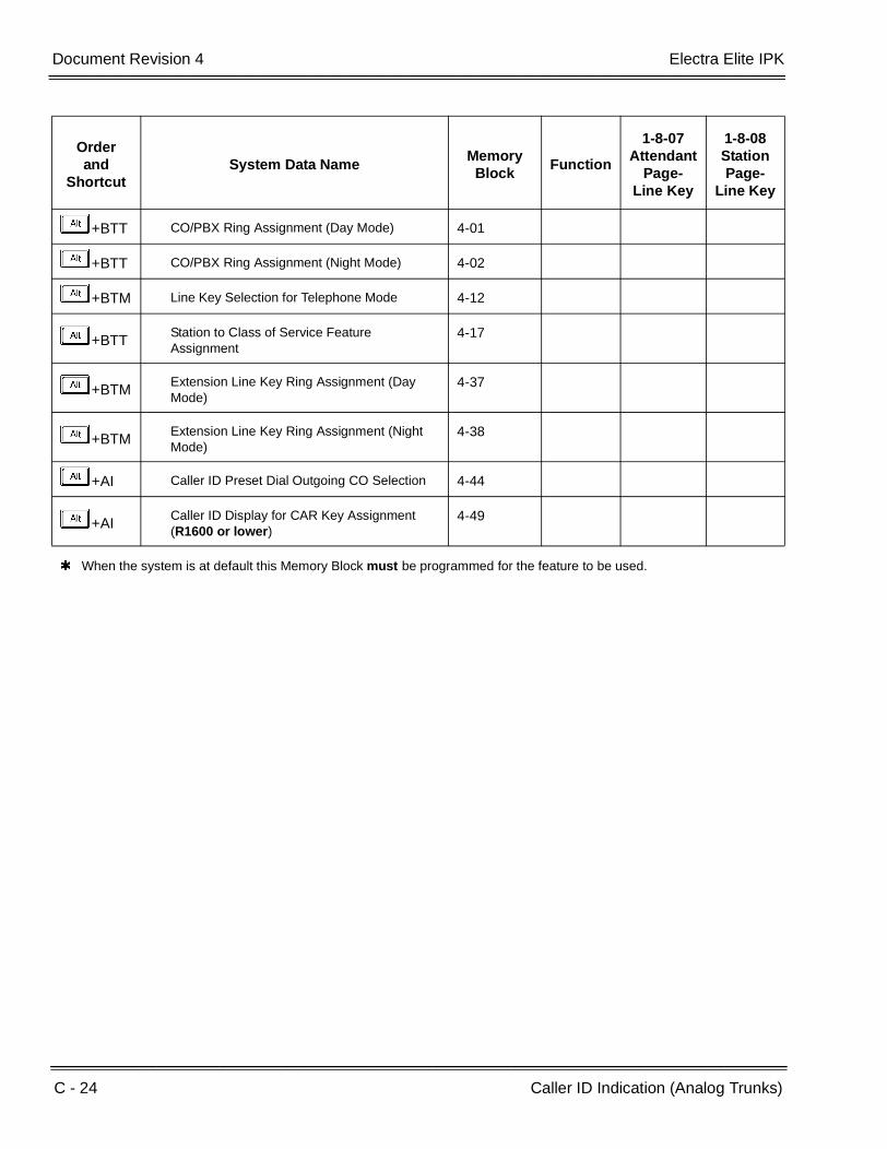
C - 24 Caller ID Indication (Analog Trunks)
___________________________________________________________________________________
___________________________________________________________________________________Document Revision 4 Electra Elite IPK
+BTT CO/PBX Ring Assignment (Day Mode) 4-01
+BTT CO/PBX Ring Assignment (Night Mode) 4-02
+BTM Line Key Selection for Telephone Mode 4-12
+BTTStation to Class of Service Feature Assignment
4-17
+BTMExtension Line Key Ring Assignment (Day Mode)
4-37
+BTMExtension Line Key Ring Assignment (Night Mode)
4-38
+AI Caller ID Preset Dial Outgoing CO Selection 4-44
+AICaller ID Display for CAR Key Assignment (R1600 or lower)
4-49
When the system is at default this Memory Block must be programmed for the feature to be used.
Orderand
ShortcutSystem Data Name
Memory Block
Function
1-8-07Attendant
Page-Line Key
1-8-08StationPage-
Line Key

Features and Specifications Manual C - 25
___________________________________________________________________________________
___________________________________________________________________________________
Caller ID Call Return C-6
FEATURE DESCRIPTION
The Caller ID Call Return feature allows the voice mail system to use Caller ID information captured with the message to call and connect the person that left the message with the voice mail user that is checking messages. After the call is ended by either party, the voice mail user returns to checking messages.
FMS Voice Mail System Software Q revision 05931 database version 6.68 or higher is required.
VMS Voice Mail System Software Q revision 00931 database version 6.68 or higher is required.
SYSTEM AVAILABILITY
Terminal Type:
All Multiline Terminals
Required Components:
VMS(2)/(4)/(8)-U( ) ETU or FMS(2)/(4)/(8)-U( ) ETU
OPERATING PROCEDURES
Caller ID Information Operation on Non-Display Telephone or Display Telephone without Softkeys:
1. Dial the EliteMail extension.
2. After message playback, EliteMail prompts to hear Caller ID number only.
- OR -
Dial K during message to stop playback, save the current message as an old message, and hear Caller ID number only.
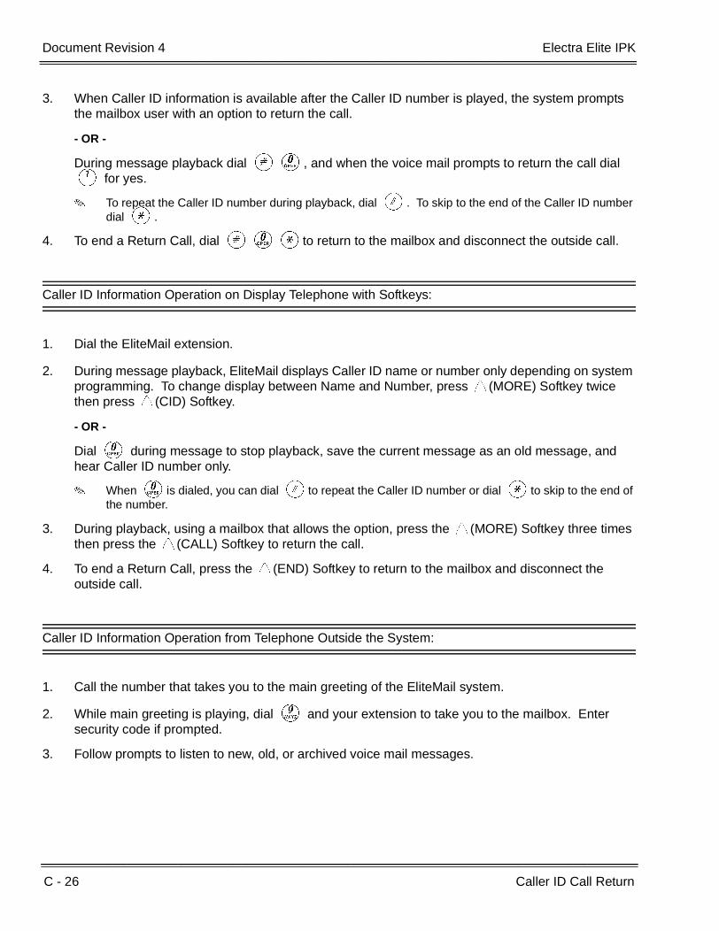
C - 26 Caller ID Call Return
___________________________________________________________________________________
___________________________________________________________________________________Document Revision 4 Electra Elite IPK
3. When Caller ID information is available after the Caller ID number is played, the system prompts the mailbox user with an option to return the call.
- OR -
During message playback dial LK, and when the voice mail prompts to return the call dial A for yes.
To repeat the Caller ID number during playback, dial L. To skip to the end of the Caller ID number dial J.
4. To end a Return Call, dial LKJto return to the mailbox and disconnect the outside call.
Caller ID Information Operation on Display Telephone with Softkeys:
1. Dial the EliteMail extension.
2. During message playback, EliteMail displays Caller ID name or number only depending on system programming. To change display between Name and Number, press V(MORE) Softkey twice then press V(CID) Softkey.
- OR -
Dial K during message to stop playback, save the current message as an old message, and hear Caller ID number only.
When Kis dialed, you can dial Lto repeat the Caller ID number or dial Jto skip to the end of the number.
3. During playback, using a mailbox that allows the option, press the V(MORE) Softkey three times then press the V(CALL) Softkey to return the call.
4. To end a Return Call, press the V(END) Softkey to return to the mailbox and disconnect the outside call.
Caller ID Information Operation from Telephone Outside the System:
1. Call the number that takes you to the main greeting of the EliteMail system.
2. While main greeting is playing, dial I and your extension to take you to the mailbox. Enter security code if prompted.
3. Follow prompts to listen to new, old, or archived voice mail messages.

Electra Elite IPK Document Revision 4
Features and Specifications Manual C - 27
___________________________________________________________________________________
___________________________________________________________________________________
4. When Caller ID information is available, EliteMail prompts to hear Caller ID number only after message playback.
- OR -
Dial K during message to stop playback, save the current message as an old message, and hear Caller ID number only.
5. When Caller ID information is available, the system prompts the mailbox user with an option to return the call after the Caller ID number is played.
- OR -
During message playback dial LK, and when voice mail prompts to return the call dial A for yes.
To repeat the Caller ID number during playback, dial L. To skip to the end of the Caller ID number dial J.
6. To end a Return Call, dial LKJto return to the mailbox and disconnect the outside call.
SERVICE CONDITIONS
General:
A caller using a telephone without Softkeys, calling from outside the system, or from a remote system is prompted to hear Caller ID information and return a call.
Return Call is available for subscriber messages and public messages.
Return Call is accessible to a subscriber during and after message playback.
Return Call is available for new and old messages.
Return Call is accessible to a subscriber using Softkeys in Softkey mode or using DTMF in voice conversation Mode.
One minute before disconnecting the original caller, voice mail plays a warning prompt and immediately before disconnecting plays a prompt to indicate that it is returning to the subscriber mailbox.
When a subscriber listens to a message from a Softkey eqipped telephone, and Caller ID information is unavailable, the voice mail system leaves the second line of the LCD blank. When Caller ID is disabled on the system, voice mail displays the message count.
From the subscriber options Softkey menu, a subscriber can access a Softkey menu that allows selection of name or number to be displayed on the LCD during message playback. The default is name. Voice mail uses this setting to determine the initial display on the LCD during playback.
Voice mail continues to display Caller ID on the LCD while the post-message playback menu is still displayed on a telephone equipped with Softkeys.
C - 28 Caller ID Call Return
___________________________________________________________________________________
___________________________________________________________________________________Document Revision 4 Electra Elite IPK
During Return Call, the voice mail port is in conference with the box owner and messages.
Internal station terminals using Call Return have the Conf key LED On.
Restrictions:
VMS revision Q008XX v 6.68 and FMS revision Q058XX v 6.68 or higher are also required.
When Centralized Voice Mail is used, the remote voice mail user gets only Caller ID number when voice mail answers incoming CO calls and performs an Await-Answer transfer to the remote user. A Call that forwards to voice mail from the remote system does not have Caller ID information.
Live Record is not available when using Return Call.
A Telephone used as an ACD Plus agent or supervisor station should not have mailboxes that support Softkeys. Softkeys can be disabled per mailbox in Access Codes Options on Easymade Application Screen, Page 5 of 6. Place * in front of Hands Free Play (Item N) to disable Softkeys for a particular station.
The Return Call feature is enabled per mailbox in Expanded Access Codes and can be enabled for internal numbers only or for both internal and external numbers.
To use this feature for long distance calls, LCR or ARS must be programmed for the voice mail ports set to dial out. Refer to the Electra Elite IPK Programming Manual for detailed programming instructions.
The enhanced Caller ID is enabled by setting CID=0,0 on the Integration Options line of Easymade Switch Setup Screen, Page 1. When Caller ID is already enabled on a system that is updated, the CID=X,Y setting must be changed to CID=0,0. Only one CID setting is allowed on this line.
The Return Call parameter must be entered on the Integration Options line of Easymade Switch Setup Screen, Page 1 to enable this voice mail feature. Default is RCV=6,10 where 6 is the number of rings voice mail tries when returning a call, and 10 is the number of minutes a retuned call can last.
A trunk access code must be entered on Easymade Switch Setup Screen, Page 1, line 9 so the Return Call feature can access a trunk to return the call. When this is not entered, the mailbox user is not prompted to return the call even when Caller ID information is available.
The Rings to answer field on Easymade Applications Screen, Page 2, line 15 must be set to 2 or greater because Caller ID information is provided from Telco between the first and second ring.
Use Memory Block 1-8-08 [Class of Service (Station) Feature Selection] Page 4, LK3 to allow (LED On) or Deny (default: LED Off) capture of Caller ID information on voice mail ports.
When 5-, 6-, or 7-digit station numbers are used, this feature is not available.

Electra Elite IPK Document Revision 4
Features and Specifications Manual C - 29
___________________________________________________________________________________
___________________________________________________________________________________
RELATED FEATURES LIST
Feature Number
Feature Name
D-8 Digital Voice Mail
L-4 Live Monitoring

C - 30 Caller ID Call Return
___________________________________________________________________________________
___________________________________________________________________________________Document Revision 4 Electra Elite IPK
THIS PAGE INTENTIONALLY LEFT BLANK

Features and Specifications Manual C - 31
___________________________________________________________________________________
___________________________________________________________________________________
Call Forward – All Call C-7
FEATURE DESCRIPTION
Call Forward – All Call forwards all calls directed to one station, to another station, Voice Mail system, or to the Attendant. This permits more efficient call processing by allowing a station to be left unattended and have calls answered at another location. Call Forward – All Call can be set or canceled at the destination station. Attendant Positions can be used to cancel Call Forward – All Call system-wide.
ENHANCEMENT(S)
With R2000 or higher, System Administration Terminal (SAT) software allows Call Forward settings to be assigned and saved as part of the database.
SYSTEM AVAILABILITY
Terminal Type:
All stations
Required Components:
None
OPERATING PROCEDURES
To set Call Forward – All Call at a forwarding station:
1. Press the Call Forward – All Call ON/OFF key.
2. Dial the station number or press E .
- OR -
1. Press A .
2. Dial FK.
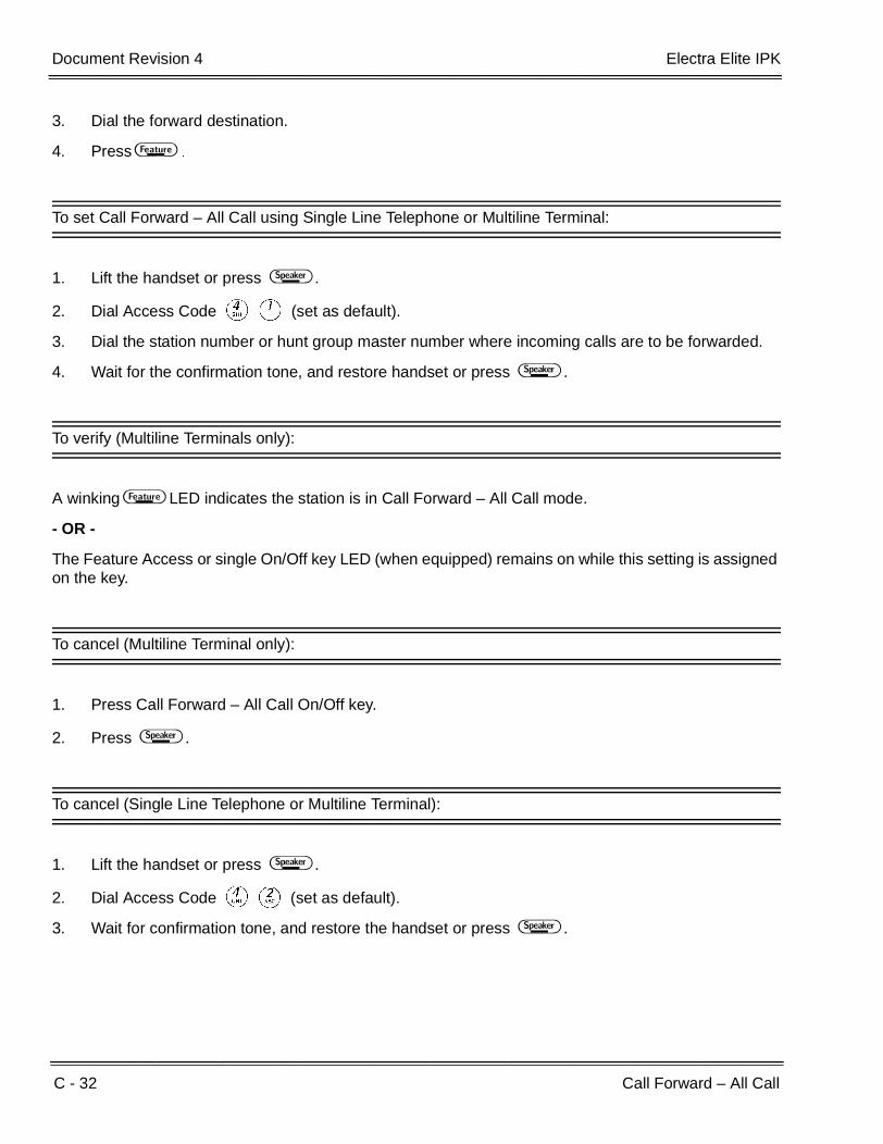
C - 32 Call Forward – All Call
___________________________________________________________________________________
___________________________________________________________________________________Document Revision 4 Electra Elite IPK
3. Dial the forward destination.
4. Press A .
To set Call Forward – All Call using Single Line Telephone or Multiline Terminal:
1. Lift the handset or press E .
2. Dial Access Code DA (set as default).
3. Dial the station number or hunt group master number where incoming calls are to be forwarded.
4. Wait for the confirmation tone, and restore handset or press E .
To verify (Multiline Terminals only):
A winking A LED indicates the station is in Call Forward – All Call mode.
- OR -
The Feature Access or single On/Off key LED (when equipped) remains on while this setting is assigned on the key.
To cancel (Multiline Terminal only):
1. Press Call Forward – All Call On/Off key.
2. Press E .
To cancel (Single Line Telephone or Multiline Terminal):
1. Lift the handset or press E .
2. Dial Access Code DB (set as default).
3. Wait for confirmation tone, and restore the handset or press E .

Electra Elite IPK Document Revision 4
Features and Specifications Manual C - 33
___________________________________________________________________________________
___________________________________________________________________________________
To set at a destination station (Attendant Positions only):
1. Lift the handset or press E .
2. Dial Access Code DG (set as default).
3. Dial the station number to be forwarded and then the destination number.
4. Wait for confirmation tone, and restore the handset or press E .
To cancel at a destination station (Attendant Positions only):
1. Lift the handset or press E .
2. Dial Access Code DH (set as default).
3. Dial the station number where forwarding is to be canceled.
4. Wait for the confirmation tone, and restore the handset or press E .
To cancel Call Forward – All Call, Busy/No Answer, and Do Not Disturb system-wide (Attendant Positions only):
1. Press A .
2. Dial Access Code FH.
3. Press A .
SERVICE CONDITIONS
General:
When a station with Call Forward assigned receives a second call, and Call Forward is set to a busy station, the second incoming call does not follow the forwarding assignment until the forwarding station becomes idle.
A line key defined as Call Forward – All Call set/cancel lights when Call Forward – All Call is set. The Feature key LED flashes when Call Forward – All Call is set.
All internal and transferred calls to the station follow the Call Forward – All Call setting.
Tie/DID and DIT/ANA line calls follow Call Forward – All Call setting.
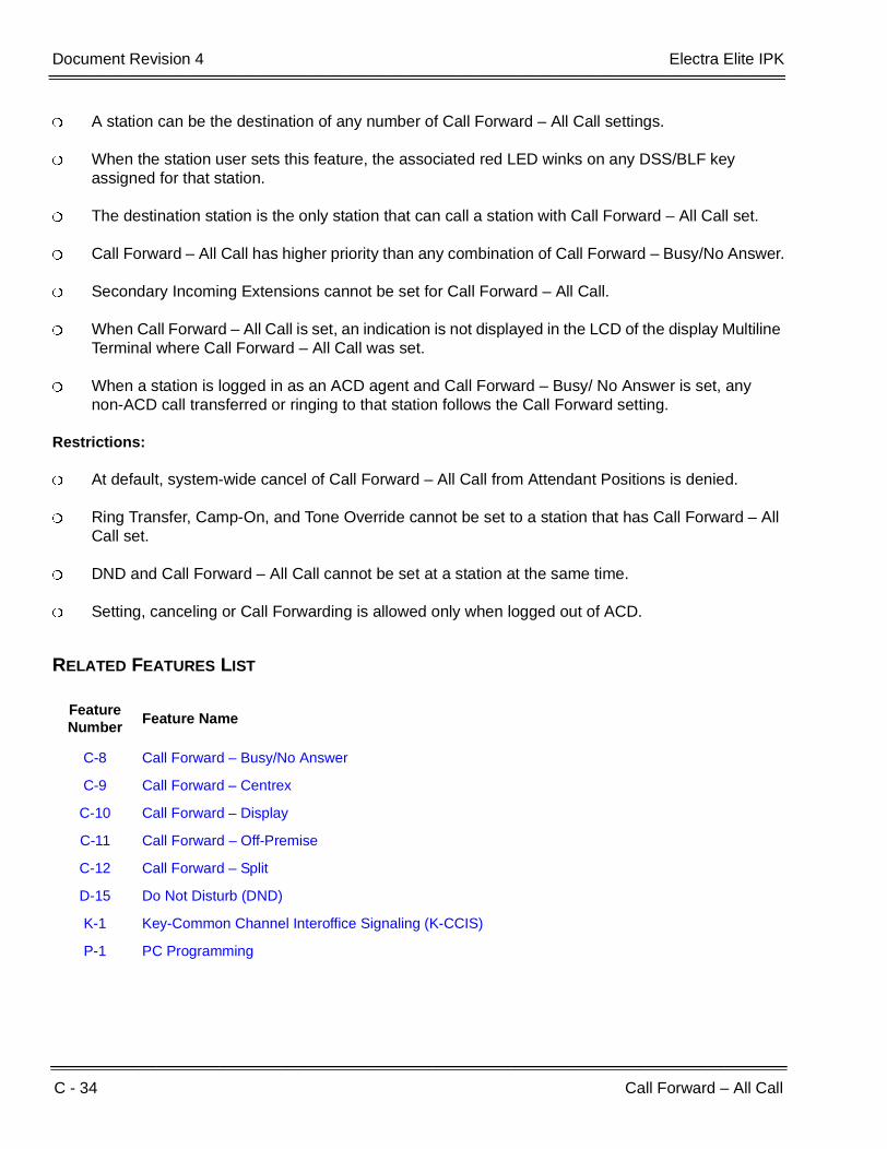
C - 34 Call Forward – All Call
___________________________________________________________________________________
___________________________________________________________________________________Document Revision 4 Electra Elite IPK
A station can be the destination of any number of Call Forward – All Call settings.
When the station user sets this feature, the associated red LED winks on any DSS/BLF key assigned for that station.
The destination station is the only station that can call a station with Call Forward – All Call set.
Call Forward – All Call has higher priority than any combination of Call Forward – Busy/No Answer.
Secondary Incoming Extensions cannot be set for Call Forward – All Call.
When Call Forward – All Call is set, an indication is not displayed in the LCD of the display Multiline Terminal where Call Forward – All Call was set.
When a station is logged in as an ACD agent and Call Forward – Busy/ No Answer is set, any non-ACD call transferred or ringing to that station follows the Call Forward setting.
Restrictions:
At default, system-wide cancel of Call Forward – All Call from Attendant Positions is denied.
Ring Transfer, Camp-On, and Tone Override cannot be set to a station that has Call Forward – All Call set.
DND and Call Forward – All Call cannot be set at a station at the same time.
Setting, canceling or Call Forwarding is allowed only when logged out of ACD.
RELATED FEATURES LIST
Feature Number
Feature Name
C-8 Call Forward – Busy/No Answer
C-9 Call Forward – Centrex
C-10 Call Forward – Display
C-11 Call Forward – Off-Premise
C-12 Call Forward – Split
D-15 Do Not Disturb (DND)
K-1 Key-Common Channel Interoffice Signaling (K-CCIS)
P-1 PC Programming
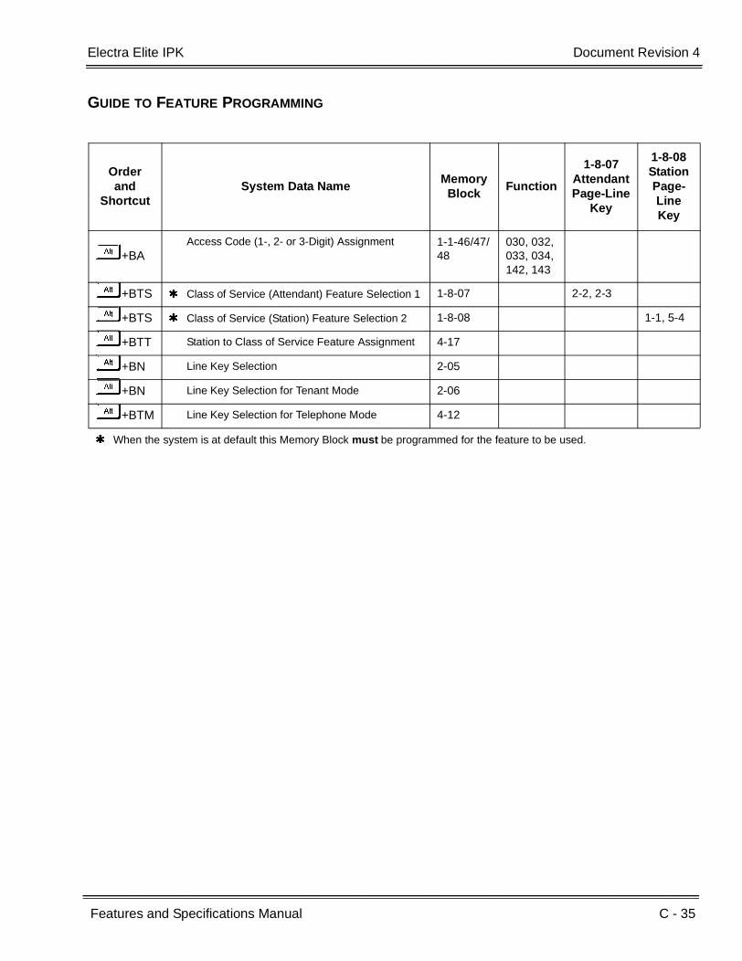
Electra Elite IPK Document Revision 4
Features and Specifications Manual C - 35
___________________________________________________________________________________
___________________________________________________________________________________
GUIDE TO FEATURE PROGRAMMING
Orderand
ShortcutSystem Data Name
Memory Block
Function
1-8-07AttendantPage-Line
Key
1-8-08StationPage-Line Key
+BAAccess Code (1-, 2- or 3-Digit) Assignment 1-1-46/47/
48030, 032,033, 034,142, 143
+BTS Class of Service (Attendant) Feature Selection 1 1-8-07 2-2, 2-3
+BTS Class of Service (Station) Feature Selection 2 1-8-08 1-1, 5-4
+BTT Station to Class of Service Feature Assignment 4-17
+BN Line Key Selection 2-05
+BN Line Key Selection for Tenant Mode 2-06
+BTM Line Key Selection for Telephone Mode 4-12
When the system is at default this Memory Block must be programmed for the feature to be used.

C - 36 Call Forward – All Call
___________________________________________________________________________________
___________________________________________________________________________________Document Revision 4 Electra Elite IPK
THIS PAGE INTENTIONALLY LEFT BLANK

Features and Specifications Manual C - 37
___________________________________________________________________________________
___________________________________________________________________________________
Call Forward – Busy/No Answer C-8
FEATURE DESCRIPTION
Call Forward – Busy/No Answer forwards calls directed to one station, to another station, Voice Mail system, or to the Attendant Position for Busy or Ring No Answer. This permits more efficient call processing by allowing calls to be routed to another station or to the Attendant Position.
ENHANCEMENT(S)
With R2000 or higher, System Administration Terminal (SAT) software allows Call Forward settings to be assigned and saved as part of the database.
SYSTEM AVAILABILITY
Terminal Type:
All Stations
Required Components:
None
OPERATING PROCEDURES
To set Call Forward – Busy/No Answer at a forwarding station:
1. Press Call Forward – Busy/No Answer ON/OFF key.
2. Dial the station number or press E .

C - 38 Call Forward – Busy/No Answer
___________________________________________________________________________________
___________________________________________________________________________________Document Revision 4 Electra Elite IPK
To cancel Call Forward – Busy/No Answer:
1. Press Call Forward – Busy/No Answer On/Off key.
2. Wait for confirmation tone, and restore handset or press E .
To set Call Forward – Busy/No Answer at any telephone:
1. Lift the handset.
2. Dial Access Code DC.
3. Dial the station number forwarding is to be set for.
4. Go on-hook.
To cancel Call Forward – Busy/No Answer at any telephone:
1. Lift the handset.
2. Dial Access Code DD.
3. Go on-hook.
To set at a destination station (Attendant Positions only):
1. Lift the handset or press E .
2. Dial Access Code DE (default).
3. Dial the station number to be forwarded and then the destination number.
4. Wait for confirmation tone, and restore the handset or press E .
To cancel at a destination station (Attendant Positions only):
1. Lift the handset or press E .
2. Dial Access Code DF (default).

Electra Elite IPK Document Revision 4
Features and Specifications Manual C - 39
___________________________________________________________________________________
___________________________________________________________________________________
3. Dial the station number where forwarding is to be canceled.
4. Wait for the confirmation tone, and restore the handset or press E .
To cancel Call Forward – All Call, Busy/No Answer, and Do Not Disturb system-wide at the Attendant Position only:
1. Press A .
2. Dial Access Code FH.
3. Press A .
SERVICE CONDITIONS
General:
When a station with Call Forward assigned receives a second call, and Call Forward is set to a busy station, the second incoming call does not follow the forwarding assignment until the forwarding station goes idle.
All internal and transferred calls to the station follow the Call Forward – Busy/No Answer setting.
Tie/DID and DIT/ANA line calls follow the Call Forward – Busy/No Answer settings.
A station can be the destination of any number of Call Forward – Busy/No Answer settings.
Call Forward – All Call has higher priority than Call Forward – Busy/No Answer.
When Call Forward – Busy/No Answer is set, camped-on calls and DIT/ANA calls forward after the No Answer Time expires.
Call Alert Notification has a significant affect on Call Forward – Busy/No Answer.
When a logged in station is an ACD agent and Call Forward – Busy/No Answer is set, any non-ACD call transferred or ringing to that station follows the Call Forward setting.
Restrictions:
Only one Call Forward – Busy/No Answer forwarding destination can be set from one station at a time.
Call Forward – Busy/No Answer forwards to another station only once (cannot chain call).
Secondary Incoming Extensions cannot be set for Call Forward – Busy/No Answer.

C - 40 Call Forward – Busy/No Answer
___________________________________________________________________________________
___________________________________________________________________________________Document Revision 4 Electra Elite IPK
Call Forwarding can be set or canceled only while logged out of ACD.
RELATED FEATURES LIST
GUIDE TO FEATURE PROGRAMMING
Feature Number
Feature Name
C-7 Call Forward – All Call
C-9 Call Forward – Centrex
C-10 Call Forward – Display
C-11 Call Forward – Off-Premise
C-12 Call Forward – Split
D-15 Do Not Disturb (DND)
K-1 Key-Common Channel Interoffice Signaling (K-CCIS)
P-1 PC Programming
Orderand
ShortcutSystem Data Name
Memory Block
Function
1-8-07Attendant
Page-Line Key
1-8-08StationPage-
Line Key
+BAAccess Code (1-, 2- or 3-Digit) Assignment 1-1-46/47/
48020~025,140, 141
+BM Call Forward - No Answer Time Selection 1-2-22
+BTS Class of Service (Attendant) Feature Selection 1
1-8-07 2-2, 2-3
+BTTStation to Class of Service Feature Assignment
4-17
+BTS Class of Service (Station) Feature Selection 2 1-8-08 2-5, 5-4
+BTM Line Key Selection for Telephone Mode 4-12
+BTT CO/PBX Busy Forward Station Assignment 4-13
+AC Station to Timer Class of Service 4-71
When the system is at default this Memory Block must be programmed for the feature to be used.

Features and Specifications Manual C - 41
___________________________________________________________________________________
___________________________________________________________________________________
Call Forward – Centrex C-9
FEATURE DESCRIPTION
The Call Forward Split for Centrex feature allows a station to forward an incoming Centrex CO call to an outside location using the same Centrex CO line to free the line for additional use.
ENHANCEMENT(S)
With R2000 or higher, System Administration Terminal (SAT) software allows Call Forward settings to be assigned and saved as part of the database.
SYSTEM AVAILABILITY
Terminal Type:
All stations
Required Components:
Centrex/PBX Trunks
OPERATING PROCEDURES
To set Call Forward – Busy/No Answer Split for Centrex:
1. Lift handset or press E .
2. Dial the Call Forward – Busy/No Answer Split Set Access Code (Default not assigned).
3. Press Bfor Centrex.
4. Dial the destination number.
5. Go on-hook or press E .

C - 42 Call Forward – Centrex
___________________________________________________________________________________
___________________________________________________________________________________Document Revision 4 Electra Elite IPK
To cancel Call Forward – Busy/No Answer Split for Centrex:
1. Lift the handset or press E .
2. Dial the Call Forward – Busy/No Answer Split Cancel Access Code (Default not assigned).
3. Press Bfor Centrex.
4. Go on-hook or press E .
To set Call Forward – All Split for Centrex:
1. Lift the handset or press E .
2. Dial the Call Forward – All Split Set Access Code (Default not assigned).
3. Press Bfor Centrex.
4. Dial the destination number.
5. Go on-hook or press E .
To cancel Call Forward – All Split for Centrex:
1. Lift the handset or press E .
2. Dial the Call Forward – All Split Cancel Access Code (Default not assigned).
3. Press Bfor Centrex.
4. Go on-hook or press E .
To set Call Forward – All Split for Centrex from destination for CAR key:
1. Lift the hand8set or press E .
2. Dial the Call Forward – All Split Set Access Code (default not assigned).
3. Press Bfor Centrex.
4. Dial the CAR key extension number.
5. Dial the Destination number.
6. Go on-hook or press E .

Electra Elite IPK Document Revision 4
Features and Specifications Manual C - 43
___________________________________________________________________________________
___________________________________________________________________________________
To cancel Call Forward – All Split for Centrex from destination for CAR key:
1. Lift the handset or press E .
2. Dial the Call Forward – All Split Cancel Access Code (Default not assigned).
3. Press Bfor Centrex.
4. Dial the CAR key extension number.
5. Go on-hook or press E .
SERVICE CONDITIONS
General:
Even when a user is logged on as an ACD agent, an individual call that does not come through the Pilot Number is forwarded.
Call Forward – Centrex supports the following:
Call Forward – All
Call Forward – Busy
Call Forward – No Answer
Call Forward – Busy/No Answer
Call Forward – All for CAR
Call Forward – Busy/No Answer for CAR
Call Forward – Centrex calls transferred from another station are forwarded when the transferred Trunk is assigned as Centrex in Memory Block 3-91 (Trunk Type Selection).
When a Centrex Trunk is DIT to a station with Call Forward – Centrex set with an incorrect registered number, the Centrex trunk recalls to the same number until the caller hangs up.
The following incoming calls follow Call Forward – Centrex when the incoming trunk is a Centrex trunk:
DIT/ANA
Station Transfer
Automated Attendant Transfer
DISA Calls
When Call Forward – Centrex is set and all trunks are changed from PBX/CTX to CO, Call Forward is cleared from memory.

C - 44 Call Forward – Centrex
___________________________________________________________________________________
___________________________________________________________________________________Document Revision 4 Electra Elite IPK
When a station is logged in as an ACD agent and Call Forward – Busy/ No Answer is set, any non-ACD call transferred or ringing to that station follows the Call Forward setting.
Restrictions:
Memory Block 3-91 must have at least one trunk assigned as PBX (or CTX) or CTX (Assume 9). When at least one trunk is not assigned as PBX/CTX, the CTX/PBX=2 option is not displayed.
Call Forward – Centrex is not supported for Call Forward – All Call by the Feature + 60 operation from destination.
Call Forward – Centrex is not supported for Single On/Off toggle key operation.
A maximum of 16 digits can be stored as the destination outside number.
Least Cost Routing cannot route the Call Forward destination number.
When a Multiline Terminal with Call Forward – Centrex set has an unplugged extension, the call is not forwarded.
Call Forwarding can be set or canceled only when an agent is logged out of ACD.
RELATED FEATURES LIST
Feature Number
Feature Name
C-7 Call Forward – All Call
C-8 Call Forward – Busy/No Answer
C-10 Call Forward – Display
C-11 Call Forward – Off-Premise
C-12 Call Forward – Split
D-15 Do Not Disturb (DND)
K-1 Key-Common Channel Interoffice Signaling (K-CCIS)
P-1 PC Programming

Electra Elite IPK Document Revision 4
Features and Specifications Manual C - 45
___________________________________________________________________________________
___________________________________________________________________________________
GUIDE TO FEATURE PROGRAMMING
Orderand
ShortcutSystem Data Name
Memory Block
Function
1-8-07Attendant
Page-Line Key
1-8-08StationPage-
Line Key
+BCT Trunk Type Selection 3-91
+BAAccess Code (1-, 2- or 3-Digit) Assignment 1-1-46/47/
48154~159
+BTS Class of Service (Attendant) Feature Selection 1 1-8-07 2-2, 2-3
+BTS Class of Service (Station) Feature Selection 2 1-8-08 1-1,2-5, 5-4
+BTT Station to Class of Service Feature Assignment 4-17
+BTM Call Forward-Busy Immediately/Delay Selection 4-42
+BM Call Forward- No Answer Time Selection 1-2-22
+AC Station to Timer Class of Service 4-71
When the system is at default this Memory Block must be programmed for the feature to be used.
C - 46 Call Forward – Centrex
___________________________________________________________________________________
___________________________________________________________________________________Document Revision 4 Electra Elite IPK
THIS PAGE INTENTIONALLY LEFT BLANK
Features and Specifications Manual C - 47
___________________________________________________________________________________
___________________________________________________________________________________
Call Forward – Display C-10
FEATURE DESCRIPTION
When a call is forwarded from one Multiline Terminal to another, the forwarding indication and forward station number are shown on the Multiline Terminal display.
ENHANCEMENT(S)
With R2000 or higher, System Administration Terminal (SAT) software allows Call Forward settings to be assigned and saved as part of the database.
SYSTEM AVAILABILITY
Terminal Type:
All Display Multiline Terminals
Required Components:
Multiline Terminals with display. Refer to C-7 Call Forward – All Call and C-8 Call Forward – Busy/No Answer features.
OPERATING PROCEDURES
None
SERVICE CONDITIONS
General:
DIT, ANA, DID, Tie, Automated Attendant transfer, and SCD calls can support Call Forward – Display.
This feature only supports forwarded calls to a primary station number. When the destination is a CAR key, the forwarding display information is not shown.
Internal calls do not show forwarding display.

C - 48 Call Forward – Display
___________________________________________________________________________________
___________________________________________________________________________________Document Revision 4 Electra Elite IPK
RELATED FEATURES LIST
Feature Number
Feature Name
C-7 Call Forward – All Call
C-8 Call Forward – Busy/No Answer
C-9 Call Forward – Centrex
C-11 Call Forward – Off-Premise
C-12 Call Forward – Split
D-15 Do Not Disturb (DND)
K-1 Key-Common Channel Interoffice Signaling (K-CCIS)
P-1 PC Programming
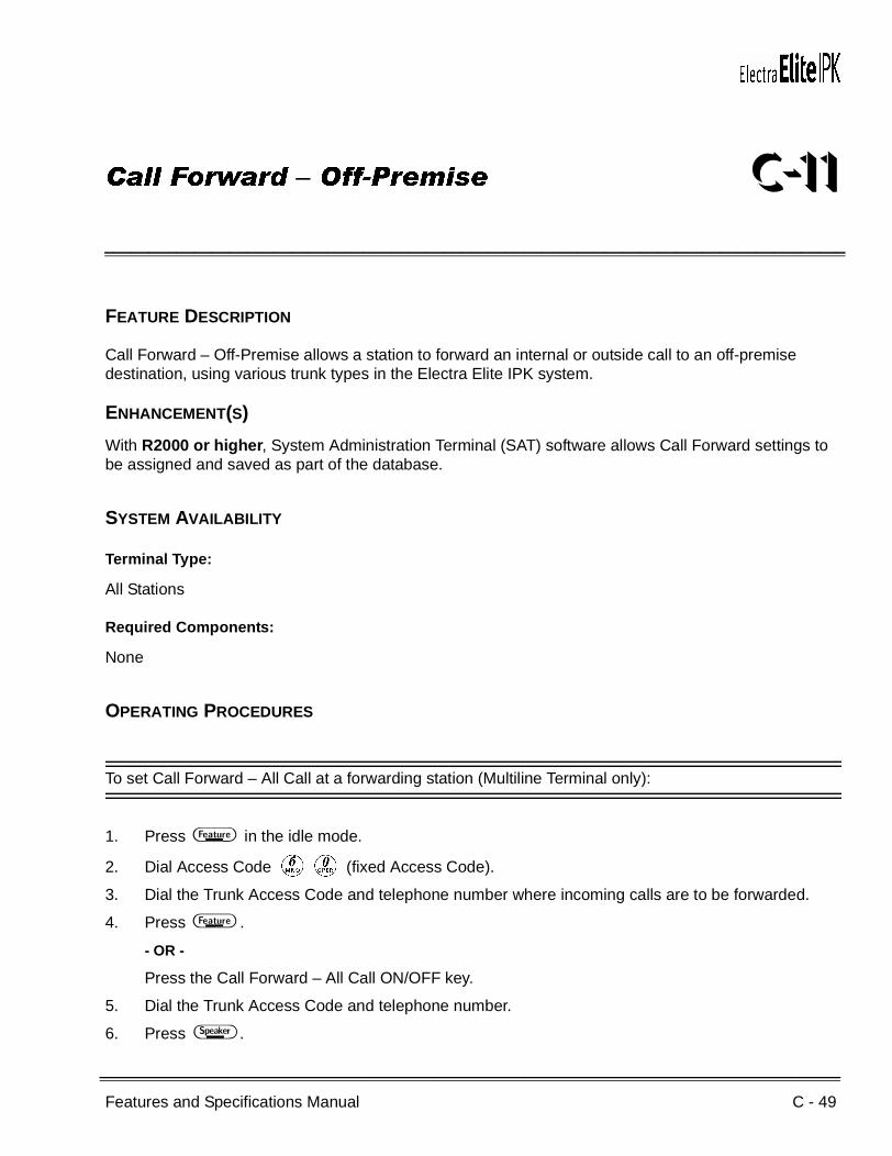
Features and Specifications Manual C - 49
___________________________________________________________________________________
___________________________________________________________________________________
Call Forward – Off-Premise C-11
FEATURE DESCRIPTION
Call Forward – Off-Premise allows a station to forward an internal or outside call to an off-premise destination, using various trunk types in the Electra Elite IPK system.
ENHANCEMENT(S)
With R2000 or higher, System Administration Terminal (SAT) software allows Call Forward settings to be assigned and saved as part of the database.
SYSTEM AVAILABILITY
Terminal Type:
All Stations
Required Components:
None
OPERATING PROCEDURES
To set Call Forward – All Call at a forwarding station (Multiline Terminal only):
1. Press A in the idle mode.
2. Dial Access Code FK (fixed Access Code).
3. Dial the Trunk Access Code and telephone number where incoming calls are to be forwarded.
4. Press A .
- OR -
Press the Call Forward – All Call ON/OFF key.
5. Dial the Trunk Access Code and telephone number.
6. Press E .

C - 50 Call Forward – Off-Premise
___________________________________________________________________________________
___________________________________________________________________________________Document Revision 4 Electra Elite IPK
To set Call Forward – All Call at a Single Line Telephone or a Multiline Terminal:
1. Lift the handset or press E .
2. Dial Access Code DA (default).
3. Dial the Trunk Access Code and telephone number where incoming calls are to be forwarded.
4. Restore the handset or press E .
To verify Call Forward – All Call (Multiline Terminals only):
A winking A LED indicates the station is in Forward – All Call mode.
- OR -
The Feature Access or One-Touch key LED (when equipped) remains on while this setting is assigned on the key.
To cancel Call Forward – All Call (Multiline Terminal only):
Press Call Forward – All Call ON/OFF key or A FI A .
To cancel Call Forward – All Call at a Single Line Telephone or a Multiline Terminal:
1. Lift the handset or press E .
2. Dial Access Code DB (default).
3. Receive confirmation tone, and restore the handset or press E .
To cancel Forward – All Call, Busy/No Answer, and Do Not Disturb system-wide (Attendant Positions only):
1. Press A .
2. Dial Access Code FH (fixed Access Code).
3. Press A .
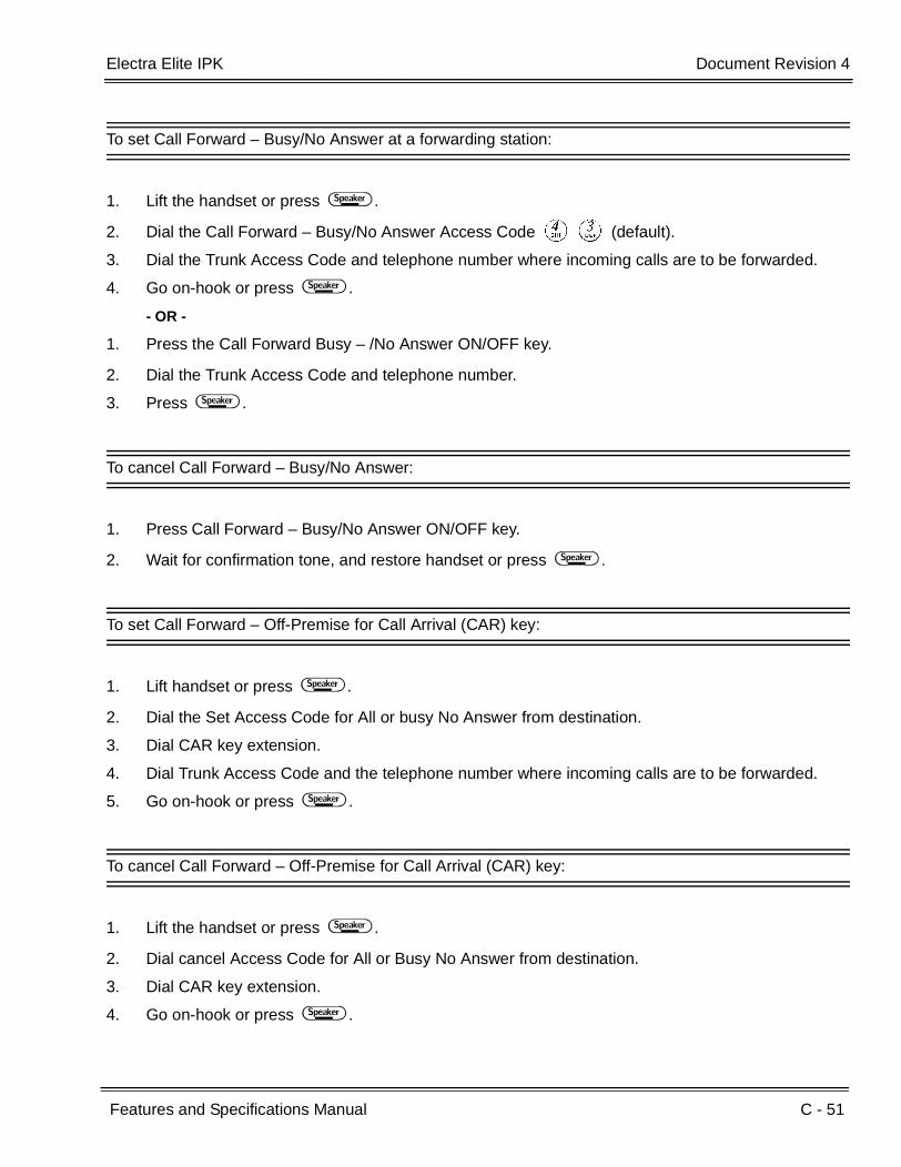
Electra Elite IPK Document Revision 4
Features and Specifications Manual C - 51
___________________________________________________________________________________
___________________________________________________________________________________
To set Call Forward – Busy/No Answer at a forwarding station:
1. Lift the handset or press E .
2. Dial the Call Forward – Busy/No Answer Access Code DC (default).
3. Dial the Trunk Access Code and telephone number where incoming calls are to be forwarded.
4. Go on-hook or press E .
- OR -
1. Press the Call Forward Busy – /No Answer ON/OFF key.
2. Dial the Trunk Access Code and telephone number.
3. Press E .
To cancel Call Forward – Busy/No Answer:
1. Press Call Forward – Busy/No Answer ON/OFF key.
2. Wait for confirmation tone, and restore handset or press E .
To set Call Forward – Off-Premise for Call Arrival (CAR) key:
1. Lift handset or press E .
2. Dial the Set Access Code for All or busy No Answer from destination.
3. Dial CAR key extension.
4. Dial Trunk Access Code and the telephone number where incoming calls are to be forwarded.
5. Go on-hook or press E .
To cancel Call Forward – Off-Premise for Call Arrival (CAR) key:
1. Lift the handset or press E .
2. Dial cancel Access Code for All or Busy No Answer from destination.
3. Dial CAR key extension.
4. Go on-hook or press E .
C - 52 Call Forward – Off-Premise
___________________________________________________________________________________
___________________________________________________________________________________Document Revision 4 Electra Elite IPK
SERVICE CONDITIONS
General:
Features like Code Restriction, or forced account codes that are enabled for the Call Forward – Off-Premise extension apply to any call that follows Call forward – Off-Premise.
The Feature key LED flashes red when Call Forward – Off-Premise (All Calls) is set from a Multiline Terminal.
The ACD/UCD overflow destination station can be set to Call Forward – Off-Premise.
The Access Codes for Call Forward set and cancel can be programmed on Feature Access keys or One-Touch keys. Press the key during the conversation with an internal or outside party to place the call on hold and dial the Access Code.
When a Call Forward ON/OFF key (All Call or Busy/No Answer) is programmed on the line key, set/cancel toggles. The Trunk Access Code and destination outside number must be dialed after pressing this key when setting Call Forward – Off-Premise.
Incoming calls from a voice mail system follow the Call Forward – Off-Premise setting.
The Call Arrival (CAR) key number can be set for Call Forward – Off-Premise.
The Speed Dial number cannot be set as the destination forward number.
When the system is installed in the Key Function (KF) mode, a Specified Line Seizure Access Code must be used when setting Call Forward – Off-Premise.
The following incoming calls can be forwarded:
CO/PBX Transfer Call
Ordinary Incoming Internal Call
Direct Inward Termination (DIT)
Assigned Night Answer (ANA)
Direct Inward Dialing (DID)
Tie Line (TIE)
Automated Attendant (AA)
When the outside party, where the call is forwarded, is busy or does not answer, the call is terminated when the calling party hangs up.
When a station is logged in as an ACD agent and Call Forward – Busy/ No Answer is set, any non-ACD call transferred or ringing to that station follows the Call Forward setting.

Electra Elite IPK Document Revision 4
Features and Specifications Manual C - 53
___________________________________________________________________________________
___________________________________________________________________________________
When the station is set for Call Forward – All Call and an outgoing outside line is unavailable, the calling party hears a busy tone.
When FT1/Tie/DID call is forwarded from an outside line to another outside line, pad control is applied according to the System Data assigned on Memory Block 3-31 (Trunk External Transmit Pad Selection) and Memory Block 3-32 (Trunk External Receive Pad Selection).
After a call is forwarded to an outside line, the call is disconnected when the Tandem Transfer Automatic Disconnect Time expires.
An alert tone is provided to both the calling party and to the destination outside party one minute before the Tandem Transfer Automatic Disconnect Time runs out.
An outgoing call is charged to the internal calling party even when the destination outside party does not answer or is busy when printed using Station Message Detail Recording (SMDR).
The destination number is output through SMDR as the call record for the station setting Call Forward – Off-Premise. When incoming outside calls are received, 999 is printed on the report. When incoming internal calls are received, the station number of the calling party is printed on the report.
Restrictions:
A maximum of 24 digits, including pauses can be stored as the destination outside number. (The Trunk Access Code is not counted as part of the 24-digit number.)
When Call Forward – All Call is set and an outgoing outside line is not available, the Automated Attendant call is not forwarded and a busy tone is sent to the calling party or the Automated Attendant switches to normal Day or Night ringing.
When Call Forward – Busy/No Answer is set, the caller hears ringback tone until a trunk is available. When an outside line is unavailable, DIT/ANA calls are not forwarded, these calls remain at the station setting the Call Forward – Off-Premise until a line is available.
Even when Call Forward – Off-Premise is set, Recall, Trunk Queuing, and Automatic Callback calls directed to the extension line are not forwarded.
The Call Forward destination number cannot be routed by Least Cost Routing.
When a Multiline Terminal in Call Forward – All Call (internal) is unplugged, it follows the all call forwarding.
When a Multiline Terminal in Call Forward – Off-Premise is unplugged, the call is not forwarded off premise.
Call Forwarding can be set or canceled only when logged out of ACD.

C - 54 Call Forward – Off-Premise
___________________________________________________________________________________
___________________________________________________________________________________Document Revision 4 Electra Elite IPK
RELATED FEATURES LIST
Feature Number
Feature Name
C-7 Call Forward – All Call
C-8 Call Forward – Busy/No Answer
C-9 Call Forward – Centrex
C-10 Call Forward – Display
C-12 Call Forward – Split
D-15 Do Not Disturb (DND)
K-1 Key-Common Channel Interoffice Signaling (K-CCIS)
P-1 PC Programming

Electra Elite IPK Document Revision 4
Features and Specifications Manual C - 55
___________________________________________________________________________________
___________________________________________________________________________________
GUIDE TO FEATURE PROGRAMMING
Orderand
ShortcutSystem Data Name
Memory Block
Function
1-8-07Attendant
Page-Line Key
1-8-08StationPage-
Line Key
+BAAccess Code (1-, 2- or 3-Digit) Assignment 1-1-46/47/
48020~ 025033, 034,140~143
+BTS Class of Service (Attendant) Feature Selection 1 1-8-07 2-2, 2-3
+BTS Class of Service (Station) Feature Selection 2 1-8-08 5-4
+BTT Station to Class of Service Feature Assignment 4-17
+BCT Trunk-to-Trunk Transfer Yes/No Selection 3-04
+BCT Polarity Reversal Selection 3-90
+BTM Line Key Selection for Telephone Mode 4-12
+BN Line Key Selection 2-05
+BN Line Key Selection for Tenant Mode 2-06
+AT Tandem Transfer Automatic Disconnect Time Selection
1-4-00
When the system is at default this Memory Block must be programmed for the feature to be used.
C - 56 Call Forward – Off-Premise
___________________________________________________________________________________
___________________________________________________________________________________Document Revision 4 Electra Elite IPK
THIS PAGE INTENTIONALLY LEFT BLANK

Features and Specifications Manual C - 57
___________________________________________________________________________________
___________________________________________________________________________________
Call Forward – Split C-12
FEATURE DESCRIPTION
The Call Forward – Split feature allows a station to forward internal or external calls to different locations, such as Voice Mail, Off Site, Attendant position or another station. Split forwarding is allowed for All Call, Busy, or Ring/No Answer to provide more efficient call processing.
ENHANCEMENT(S)
With R2000 or higher, System Administration Terminal (SAT) software allows Call Forward settings to be assigned and saved as part of the database.
SYSTEM AVAILABILITY
Terminal Type:
All Stations
Required Components:
None
OPERATING PROCEDURES
To set Call Forward – Busy/No Answer Split:
1. Lift handset or press E .
2. Dial the Call Forward – Busy/No Answer Split Set Access Code (default not assigned).
3. Dial Afor Internal or Kfor External.
4. Dial the destination number.
5. Press E .

C - 58 Call Forward – Split
___________________________________________________________________________________
___________________________________________________________________________________Document Revision 4 Electra Elite IPK
To cancel Call Forward – Busy/No Answer Split:
1. Lift handset or press E .
2. Dial the Call Forward – Busy/No Answer Split Cancel Access Code (default not assigned).
3. Dial Afor Internal or Kfor External.
4. Press E .
To set Call Forward – All Split:
1. Lift handset or press E .
2. Dial the Call Forward – All Split Set Access Code (default not assigned).
3. Dial Afor Internal or Kfor External.
4. Dial the Trunk Access Code and the telephone number for the destination number.
5. Press E .
To cancel Call Forward – All Split:
1. Lift handset or press E .
2. Dial the Call Forward – All Split Cancel Access Code (default not assigned).
3. Dial Afor Internal or Kfor External.
4. Press E .
To set Call Forward – All or Busy/No Answer Split from destination CAR key:
1. Lift handset or press E .
2. Dial the Set Access Code for All or Busy/No Answer Split from destination (default not assigned).
3. Dial Afor Internal or Kfor External.
4. Dial CAR key or Station Number to be forwarded.
5. Dial the Trunk Access Code and the telephone number for the destination number.
6. Go on-hook or press E .

Electra Elite IPK Document Revision 4
Features and Specifications Manual C - 59
___________________________________________________________________________________
___________________________________________________________________________________
To cancel Call Forward – All or Busy/No Answer Split from destination CAR key:
1. Lift handset or press E .
2. Dial the Cancel Access Code for All or Busy/No Answer from destination (default not assigned).
3. Dial Afor Internal or Kfor External.
4. Dial CAR key or Station Number to be Forwarded.
5. Go on-hook or press E .
SERVICE CONDITIONS
General:
Even when a user logs on as an ACD agent, an individual call not through the Pilot Number is Call Forwarded.
When a call is transferred to an extension with Call Forward – Split set, the Split feature follows the Internal destination when the Transfer, Hold, or Conf key is pressed.
Call Forward – Split supports the following:
Call Forward – All Call
Call Forward – Busy
Call Forward – No Answer
Call Forward – Busy/No Answer
Call Forward – Busy/No Answer for CAR
Call Forward – Off-Premise can be set for all of the above.
When setting Call Forward, both Internal and External calls have the same forwarding destination when any other forwarding is used.
The Call Forward On/Off toggle key LED is on when both Internal and External calls have the same forwarding destination.
When a station is logged in as an ACD agent and Call Forward – Busy/ No Answer is set, any non-ACD call transferred or ringing to that station follows the Call Forward setting.
Restrictions:
The Split feature is not supported for Call Forward – All Call by the FEATURE + 60 operation from destination.

C - 60 Call Forward – Split
___________________________________________________________________________________
___________________________________________________________________________________Document Revision 4 Electra Elite IPK
The Split feature is not supported for Single On/Off toggle key operation.
Call Forwarding can be set or canceled only when logged out of ACD.
RELATED FEATURES LIST
GUIDE TO FEATURE PROGRAMMING
Feature Number
Feature Name
C-7 Call Forward – All Call
C-8 Call Forward – Busy/No Answer
C-9 Call Forward – Centrex
C-10 Call Forward – Display
C-11 Call Forward – Off-Premise
D-15 Do Not Disturb (DND)
K-1 Key-Common Channel Interoffice Signaling (K-CCIS)
P-1 PC Programming
Orderand
ShortcutSystem Data Name
Memory Block
Function
1-8-07AttendantPage-Line
Key
1-8-08StationPage-
Line Key
+BA Access Code (1-, 2- or 3-Digit) Assignment 1-1-46/47/48
154~159
+BTS Class of Service (Attendant) Feature Selection 1 1-8-07 2-2, 2-3
+BTS Class of Service (Station) Feature Selection 2 1-8-08 1-1, 2-5, 5-4
+BTT Station to Class of Service Feature Assignment 4-17
+BTM Call Forward-Busy Immediately/Delay Selection 4-42
+BM Call Forward- No Answer Time Selection 1-2-22
+BCT Truck-to-Trunk Transfer Yes/No Selection 3-04
+AC Station to Timer Class of Service 4-71
When the system is at default this Memory Block must be programmed for the feature to be used.
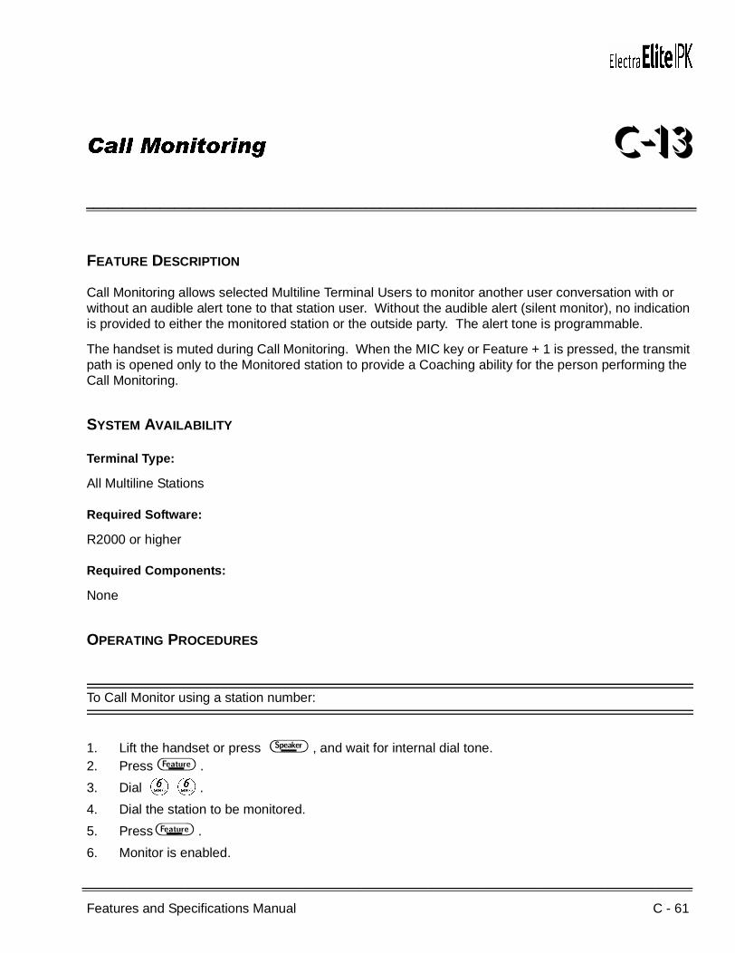
Features and Specifications Manual C - 61
___________________________________________________________________________________
___________________________________________________________________________________
Call Monitoring C-13
FEATURE DESCRIPTION
Call Monitoring allows selected Multiline Terminal Users to monitor another user conversation with or without an audible alert tone to that station user. Without the audible alert (silent monitor), no indication is provided to either the monitored station or the outside party. The alert tone is programmable.
The handset is muted during Call Monitoring. When the MIC key or Feature + 1 is pressed, the transmit path is opened only to the Monitored station to provide a Coaching ability for the person performing the Call Monitoring.
SYSTEM AVAILABILITY
Terminal Type:
All Multiline Stations
Required Software:
R2000 or higher
Required Components:
None
OPERATING PROCEDURES
To Call Monitor using a station number:
1. Lift the handset or press E , and wait for internal dial tone.2. Press A .
3. Dial FF.
4. Dial the station to be monitored.
5. Press A .
6. Monitor is enabled.

C - 62 Call Monitoring
___________________________________________________________________________________
___________________________________________________________________________________Document Revision 4 Electra Elite IPK
To Call Monitor using an outside line number:
1. Lift the handset or press E , and wait for internal dial tone.
2. Press A .
3. Dial FF.
4. Dial J.
5. Dial the CO/PBX number to be monitored.
6. Press A .
7. Monitor is enabled.
To Call Monitor using an outside line key:
1. Lift the handset or press E , and wait for internal dial tone.
2. Press A .
3. Dial FF.
4. Press the CO/PBX line key to be monitored.
5. Monitor is enabled.
SERVICE CONDITIONS
General:
Each Call Monitoring in progress requires an available conference circuit.
The following actions are ignored at the station that initiated Call Monitoring:
Answer Key
Conference Key
Dialing
Hold Key
Recall Key
Redial Key
Transfer Key

Electra Elite IPK Document Revision 4
Features and Specifications Manual C - 63
___________________________________________________________________________________
___________________________________________________________________________________
When Call Monitoring is denied, DENIED is displayed on the LCD.
Call Monitoring is allowed even when the monitored station is in Do Not Disturb mode.
When the station user being monitored places the call on Hold or Exclusive Hold, the monitoring station is disconnected and the trunk is placed on hold.
Restrictions:
Call Monitoring is not allowed for internal calls.
Call Monitoring is not allowed until the Elapsed Call Time starts.
Call Monitoring is not allowed for outside lines on hold.
Add-On Conference calls cannot be monitored.
Busy trunks involved in a Trunk-to-Trunk Transfer cannot be monitored.
Call Monitoring is not permitted when all 16 Add-On Conferences are busy.
Live Record (using Digital Voice Mail) during Call Monitoring is not supported.
Call Monitoring is not allowed for private lines.
Call Monitoring cannot be used on outside lines for another tenant unless the lines are assigned to both tenants.
Data Line Security prevents a station from being monitored, even when Call Monitoring is allowed in Class of Service.
A Single Line Telephone (SLT) or PSII user cannot activate Call Monitoring; however, the conversation on an SLT can be monitored.
RELATED FEATURES LIST
Feature Number
Feature Name
A-20 Automatic Call Distribution
B-3 Barge-In
E-7 Elite ACD Plus

C - 64 Call Monitoring
___________________________________________________________________________________
___________________________________________________________________________________Document Revision 4 Electra Elite IPK
GUIDE TO FEATURE PROGRAMMING
Orderand
ShortcutSystem Data Name
Memory Block
Function
1-8-07Attendant
Page-Line Key
1-8-08StationPage-
Line Key
+BTS Class of Service (Station) Feature Selection 2 1-8-08 P6, LK6,
P6, LK7
+BM Start Time Selection 1-1-05
+BCS Private line Assignment 1-1-29
+BTS Call Monitoring Alert Tone Assignment 1-1-86
+BN Trunk to Tenant Assignment 2-01
+BTTStation to Class of Service Feature Assignment
4-17
+BTT SLT Data Line Security Assignment 4-90
+AC Station to Timer Class of Service 4-71
When the system is at default this Memory Block must be programmed for the feature to be used.
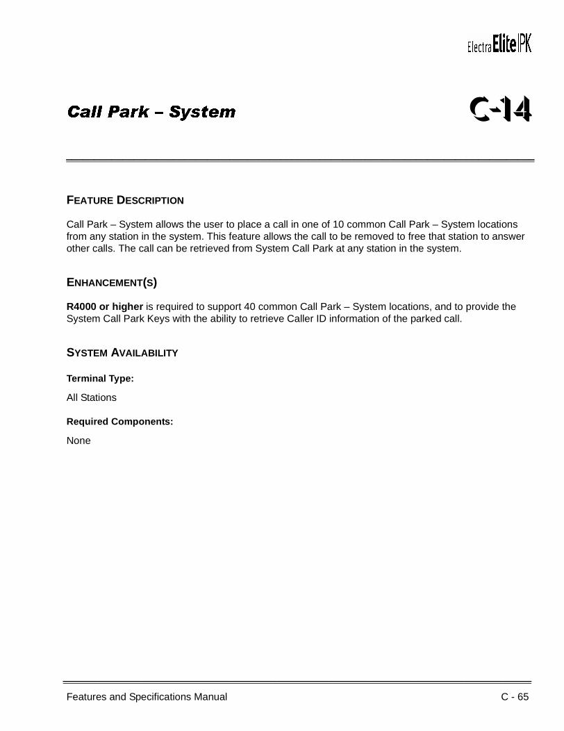
Features and Specifications Manual C - 65
___________________________________________________________________________________
___________________________________________________________________________________
Call Park – System C-14
FEATURE DESCRIPTION
Call Park – System allows the user to place a call in one of 10 common Call Park – System locations from any station in the system. This feature allows the call to be removed to free that station to answer other calls. The call can be retrieved from System Call Park at any station in the system.
ENHANCEMENT(S)
R4000 or higher is required to support 40 common Call Park – System locations, and to provide the System Call Park Keys with the ability to retrieve Caller ID information of the parked call.
SYSTEM AVAILABILITY
Terminal Type:
All Stations
Required Components:
None

C - 66 Call Park – System
___________________________________________________________________________________
___________________________________________________________________________________Document Revision 4 Electra Elite IPK
OPERATING PROCEDURES
To set at a Multiline Terminal:
1. With a call in progress, press G , and wait for internal dial tone (the party is placed on Hold).
2. Dial the Call Park Set Access Code DJ (set as default).
3. Dial the Call Park location number (K~Ior KK~CI), and wait for confirmation tone; the call is parked.
K~Iis used when the system is assigned for 10 Call Park Locations;
KK~CI is used when the system is assigned for 40 Locations.
4. Restore the handset.
To set at a Single Line Telephone:
1. With a call in progress, press the hookswitch, and wait for internal dial tone (the party is placed on Exclusive Hold).
2. Dial the Call Park Set Access CodeDJ (set as default).
3. Dial the Call Park location number (K~I or KK~CI), and wait for confirmation tone; the call is parked.
K~Iis used when the system is assigned for 10 Call Park Locations;
KK~CI is used when the system is assigned for 40 Locations.
4. Restore the handset.
To retrieve a parked call at either a Multiline Terminal or a Single Line Telephone:
1. Go off-hook, and wait for internal dial tone.
2. Dial the Call Park Retrieve Access Code DL (set as default).
3. Dial the Call Park location number (K~I or KK~CI) of the call to be retrieved.
K~Iis used when the system is assigned for 10 Call Park Locations;
KK~CI is used when the system is assigned for 40 Locations.
4. Talk with party.

Electra Elite IPK Document Revision 4
Features and Specifications Manual C - 67
___________________________________________________________________________________
___________________________________________________________________________________
To program a System Call Park Key:
1. Press A .
2. Press B .
3. Press Feature Access or One Touch key.
4. Dial Lto indicate A to the Electra Elite system.
5. Dial the Feature Access Code ( EJ plus System Park Location K~ Ior
KK~CI) depending on system setting data.
6. Press A .
To set at a Multiline Terminal using the System Call Park Key:
1. With a call in progress:Press the programmed System Call Park Line Key.
- OR -
Press G , and wait for internal dial tone.
Press the programmed System Call Park Line Key.
2. Restore the handset.
The System Call Park Key is Red.
To retrieve a parked call at a Multiline Terminal using the System Call Park Key:
1. Go off-hook, and wait for internal dial tone.
2. Press the Red System Call Park Line Key.
3. Talk with party.

C - 68 Call Park – System
___________________________________________________________________________________
___________________________________________________________________________________Document Revision 4 Electra Elite IPK
To view Caller ID information of a parked call at a Multiline Terminal:
1. A System Call Park key is red.
2. Press A .
3. Press the Red System Call Park key.
Caller ID information is displayed for five seconds.
To view Caller ID information of a parked call at an Attendant Station:
1. A System Call Park key is red.
2. Press A .
3. Press the DSS key assigned for System Call Park.
Caller ID information is displayed for five seconds.
SERVICE CONDITIONS
General:
Any call left in Call Park more than the programmed time recalls to the station where the call was originally parked. The Call Park location becomes idle after the recall, and the trunk line key switches to Non-Exclusive Hold.
When attempting to set Call Park to a busy Call Park location, and a busy tone is heard, Step Call can be used to access an idle location to park the call.
When a station other than the station originally used to park the call retrieves the call, the SMDR records a transfer to the station where the call is retrieved.
When a Call Park is in recall mode, the call cannot be picked up using the Call Park retrieval Access Code.
Call Park is set and retrieved from internal dial tone.
Outside calls and internal calls can be parked from any station.
Conference calls cannot be parked.
When user attempts to set Call Park and all Call Park locations are busy, a busy tone is heard and ALL PARK BUSY is displayed on Display Multiline Terminals.
Electra Elite IPK Document Revision 4
Features and Specifications Manual C - 69
___________________________________________________________________________________
___________________________________________________________________________________
When trying to set Call Park, and a busy tone is heard, Step Parking can be used to access an idle location in the same tens group. For example, when 25 is busy, dial 6 to place the call in Location 26.
R4000 or higher allows System Call Park keys to be assigned to the Attendant Add-On Console.
System Call Park Keys provide a visual indication of the Park location when programmed on either Feature Access Keys, One Touch Keys, or the Attendant Add-On Console.
Caller ID information can be recalled when a trunk call with Caller ID information is parked using the System Call Park Keys. Caller ID information is displayed for five seconds.
Station Caller ID information can be recalled when an ICM Call is parked using the System Call Park Keys. Caller ID information is displayed for five seconds.
Station users across K-CCIS can retrieve calls parked in a System Call Park Key location.
The System Call Park Key flashes green when the Call Park Recall time expires.
Restrictions:
A station user cannot retrieve a Parked Call that is recalling across K-CCIS.
A Systems being upgraded from R3500 or lower to R4000 or higher, has a Call Park selection of 10 Call Park Locations (LK 1). With R4000 or higher, the CPU defaults to 10 Call Park Locations (LK 1).
When a user tries to park a current call in an occupied location using the System Call Park Keys, the current call is placed on hold and the parked call is retrieved.

C - 70 Call Park – System
___________________________________________________________________________________
___________________________________________________________________________________Document Revision 4 Electra Elite IPK
GUIDE TO FEATURE PROGRAMMING
Orderand
ShortcutSystem Data Name
Memory Block
Function
1-8-07Attendant
Page-Line Key
1-8-08StationPage-
Line Key
+BAAccess Code (1-, 2- or 3-Digit) Assignment 1-1-46/47/
48047, 048
+BM System Call Park Recall Time Selection 1-2-23
+BTDAttendant Add-On Console Key selection 1-6-05 Page 3,
LK7
+BM
Call Park Selection 1-8-51 LK1(10) (default)
LK2 (40)
+AC
Station to Timer Class of Service
Ports 1 and 2 are in Class 1 by default. All other ports are in Class 2 by default.
4-71
When the system is at default this Memory Block must be programmed for the feature to be used.

Features and Specifications Manual C - 71
___________________________________________________________________________________
___________________________________________________________________________________
Call Pickup Direct C-15
FEATURE DESCRIPTION
Call Pickup Direct allows station users to answer any call directed at another station. This permits efficient handling of calls that are directed to unattended stations.
SYSTEM AVAILABILITY
Terminal Type:
All Stations
Required Components:
None
OPERATING PROCEDURES
To receive an incoming call:
1. Unattended station A receives a call.
2. Press E or lift the handset at station B.
3. Dial Access Code FG (set as default).
4. Dial the number for station A and begin talking.
C - 72 Call Pickup Direct
___________________________________________________________________________________
___________________________________________________________________________________Document Revision 4 Electra Elite IPK
SERVICE CONDITIONS
General:
The Call Pickup Direct feature answers the following calls:
Intercom Ringing
Intercom Voice
CO/PBX Incoming
DIT/ANA
VRS/Automated Attendant Transfer
DID/Tie Incoming
ACD/UCD Incoming
Camp-On Recall
Hold Recall
Off-Hook Ringing
Transfer Recall
Call Forward
Delayed Ringing
CO Ring Forward
Ring Transfer
Step Call
Call Park Recall
The Call Pickup Direct Feature cannot answer the following calls:
CAR extension number
Call Alert
A station that is in DND mode
Calls to Private Lines when Private Line is not assigned at the station doing the call pickup
Trunk Queuing Recall
Automatic Callback Ringing

Electra Elite IPK Document Revision 4
Features and Specifications Manual C - 73
___________________________________________________________________________________
___________________________________________________________________________________
When different calls are received at a station, the following Call Pickup priorities are used by the system:
1. Internal Calls
2. DIT/ANA Calls
DID Calls
E&M Calls
3. VRS/Automated Attendant Transfer Calls
4. Ring Transfer Calls
5. CO/PBX Calls
6. Calls on SIE/CAR keys
7. Recalls (DIT/ANA, DID, E&M calls are the same priority)
When two or more calls of the same type are received at a station, the following Call Pickup priorities are used by the system:
Ordinary Incoming CO/PBX Calls
After the first call is picked up, the lowest numbered CO/PBX Trunk is picked up (i.e., when acall is received on Trunks 01 and 02, Trunk 01 is picked up first).
Calls on SIE/CAR keys
First In/First Out
DIT, DID, VRS/Automated Attendant Transfer Calls
First In/First Out
Ring Transferred CO/PBX Call
After the first call is picked up, the lowest numbered CO/PBX Trunk is picked up (i.e., when acall is received on Trunks 01 and 02, Trunk 01 is picked up first).
Recalls
After the first internal call is picked up, the lowest numbered CO/PBX Trunk is picked up (i.e.,when a call is received on Trunks 01 and 02, Trunk 01 is picked up first).
CAR/SIE incoming calls are answered by dialing the station number where the CAR/SIE call is ringing.
The Call Pickup Direct Access Code can be programmed on a Feature Access key or One-Touch key.
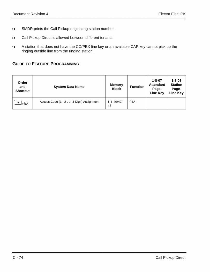
C - 74 Call Pickup Direct
___________________________________________________________________________________
___________________________________________________________________________________Document Revision 4 Electra Elite IPK
SMDR prints the Call Pickup originating station number.
Call Pickup Direct is allowed between different tenants.
A station that does not have the CO/PBX line key or an available CAP key cannot pick up the ringing outside line from the ringing station.
GUIDE TO FEATURE PROGRAMMING
Orderand
ShortcutSystem Data Name
Memory Block
Function
1-8-07Attendant
Page-Line Key
1-8-08StationPage-
Line Key
+BAAccess Code (1-, 2-, or 3-Digit) Assignment 1-1-46/47/
48042
Features and Specifications Manual C - 75
___________________________________________________________________________________
___________________________________________________________________________________
Call Pickup – Group C-16
FEATURE DESCRIPTION
A Station user can answer a call intended for another station either in the same programmed Call Pickup group (Tenant Assignment) or another Tenant Group, depending on the Call Pickup Access Code used. Incoming ringing outside calls to a station can be answered by any station in the same Call Pickup group or by stations in other Tenant groups. The system can be subdivided into 48 separate Tenant groups, each with its own outside line assignments.
SYSTEM AVAILABILITY
Terminal Type
All Stations
Required Components:
None
OPERATING PROCEDURES
To use this feature at a station:
1. Station A is receiving a call.
2. Press E or lift the handset at station B.
3. Dial the Call Pickup Access Code.
Default Access Codes are:
FHIntra-Tenant Call Pickup
FINight Chime Call Pickup
FJCall Pickup CO/PBX in Same Tenant
4. Use the handset to talk to the party calling station A.
C - 76 Call Pickup – Group
___________________________________________________________________________________
___________________________________________________________________________________Document Revision 4 Electra Elite IPK
SERVICE CONDITIONS
General:
Call Pickup Groups are created by assigning Tenant Groups. A maximum of 48 Call Pickup Groups can be assigned.
All Call Pickup Access Codes are valid for both Day Mode and Night Mode except the Night Call Pickup Access Code. The Night Call Pickup Access Code is valid when a tenant is in Night Mode and the Night Chime feature is programmed.
An incoming Tie/DID call is first treated as an internal call. After timeout (default: No Timeout), the incoming call is treated as an incoming CO/PBX outside call.
When incoming calls terminate on two or more stations simultaneously, the internal call with the lowest station number is answered first.
To Call Pickup a Secondary Incoming Extension, a user must dial the applicable Access Code to pick up the original call.
Restrictions:
Voice announced internal calls cannot be picked up in the same Tenant Group.
Data Assignment:
Use Memory Blocks 1-1-46 and 1-1-47 [Access Code (1- or 2-Digit) Assignment] to assign the following other Call Pickups that do not have an Access Code at default:
Call Pickup CO/PBX by Tenant (1-digit)
Call Pickup CO/PBX/Centrex by Tenant (2-digit)
Call Pickup CO/PBX for other Tenants
Internal/CO/PBX Transfer Call Pickup in Same Tenant
Call Pickup CO/PBX in Same Tenant
Call Pickup (Tie only) in Same Tenant
Call Pickup (PBX only) in Same Tenant
Call Pickup (CO only) in Same Tenant
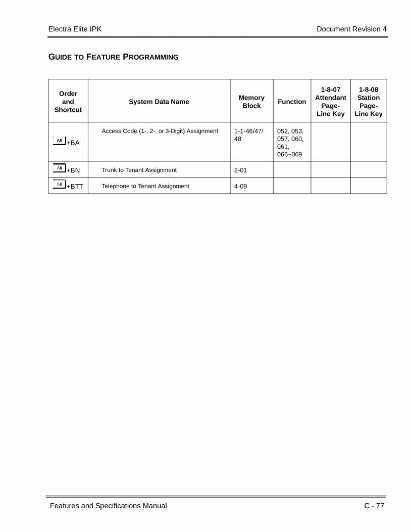
Electra Elite IPK Document Revision 4
Features and Specifications Manual C - 77
___________________________________________________________________________________
___________________________________________________________________________________
GUIDE TO FEATURE PROGRAMMING
Orderand
ShortcutSystem Data Name
Memory Block
Function
1-8-07Attendant
Page-Line Key
1-8-08StationPage-
Line Key
+BA
Access Code (1-, 2-, or 3-Digit) Assignment 1-1-46/47/48
052, 053,057, 060,061, 066~069
+BN Trunk to Tenant Assignment 2-01
+BTT Telephone to Tenant Assignment 4-09

C - 78 Call Pickup – Group
___________________________________________________________________________________
___________________________________________________________________________________Document Revision 4 Electra Elite IPK
THIS PAGE INTENTIONALLY LEFT BLANK

Features and Specifications Manual C - 79
___________________________________________________________________________________
___________________________________________________________________________________
Cascade CPU C-17
FEATURE DESCRIPTION
This feature provides a cost effective means to increase the size of a system by connecting multiple systems using the EXPT(2)-U( ) ETU that allows the functionality of two DTI-U( ) ETUs in one ETU.
SYSTEM AVAILABILITY
Terminal Type:
All Multiline Terminals
Required Software:
R1700 or higher is required.
Required Components:
EXPT(2)-U( ) ETUCCH(4)-U( ) ETUCLKG-U( ) Unit (Phase Lock OscillatorMIFM-U( ) ETU with KMM(1.00)U Unit, MIFM-U20 with KMM-U20 Unit, or SPE(M)-U( ) ETU (for call routing using LCR)
OPERATING PROCEDURES
Normal Call Handling procedures apply.

C - 80 Cascade CPU
___________________________________________________________________________________
___________________________________________________________________________________Document Revision 4 Electra Elite IPK
The following diagram shows the function of the EXPT(2)-U( ) ETU.
For System 1, a DTI ETU is assigned in slot S1 of the phantom KSU 2 for System 1 and connected to a DTI in slot S1 of KSU 1 for system 2. The EXP-U( ) in KSU 2 is connected to the CPU in System 1, KSU 1.
This configuration is replaced by the EXPT ETU assigned as a DTI in slot S1 of KSU 1 for System 2 connected to the CPU in System 1, KSU 1. One EXPT(2)-U( ) ETU replaces the EXP-U( ) ETU, two DTI-U30 ETUs, and one KSU.
Several configuration examples using the EXPT(2)-U( ) are shown in the following diagrams and table.
CPUI
DTI
CCH
System #2KSU #1
EXP
DTI
CPUI
CCH
System #1KSU #1
System #1KSU #2
CPUI
EXPT
CCH
System #2KSU #1
CPUI
CCH
System #1KSU #1

Electra Elite IPK Document Revision 4
Features and Specifications Manual C - 81
___________________________________________________________________________________
___________________________________________________________________________________
Example 1 Two Systems Two KSU’s
C P U I
E X P T
C C H
System #1 Cabinet #1
System #2 Cabinet #1
C P U I
C C H
Example 2 Two Systems Three KSU’s
E X P
C C H
System #1 Cabinet #1
System #1 Cabinet #2
C P U I
C P U I
E X P T
C C H
System #2 Cabinet #1
Example 3 Three Systems Three KSU’s
C P U I
E X P T
C C H
System #1 Cabinet #1
System #2 Cabinet #1
C P U I
C C H
C P U I
E X P T
C C H
System #3 Cabinet #1
Example 4 Two Systems Four KSU’s
E X P
C C H
System #1 Cabinet #1
System #1 Cabinet #2
C P U I
C P U I
E X P T
System #2 Cabinet #1
E X P
C C H
System #2 Cabinet #2
Example 5 Three Systems
Four KSU’s
E X P
C C H
System #1 Cabinet #1
System #1 Cabinet #2
C P U I
C P U I
E X P T
C C H
System #2 Cabinet #1
C P U I
E X P T
C C H
System #3 Cabinet #1
Example 6 Four Systems Four KSU’s
C P U I
E X P T
C C H
System #1 Cabinet #1
System #2 Cabinet #1
C P U I
C C H
C P U I
E X P T
C C H
System #3 Cabinet #1
C P U I
E X P T
C C H
System #4 Cabinet #1

C - 82 Cascade CPU
___________________________________________________________________________________
___________________________________________________________________________________Document Revision 4 Electra Elite IPK
Note 1. The number of available Interface (IF) slots is the number of slots left after the EXPT(2)-U( ) and CCH(4)-U( ) ETUs are installed.
Note 2. The calculation of maximum number of usable Trunks is based on the EXPT(2)-U( ) ETU being assigned as a full T1 (24 Trunks).
Note 3. The calculation of maximum number of usable Stations is restricted by power limitations of the KSU (No single KSU can support more than 80 Multiline Terminals.
Example
Number of KSU's
Number of
CPU's
Number of
EXPT(2)-U( ) ETU's
System Number
Number of Available IF Slots (Note 1)
Maximum Number of
Usable Trunks (Note 2)
Maximum Number of
Usable Stations (Note 3)
1 7 40 80 2 6 40 80
#1
2
2
1
Total(s) 13 80 * 160 * 1 15 40 120 2 6 40 80
#2
3
2
1
Total(s) 21 80 * 200 * 1 7 40 80 2 6 16 80 3 6 40 80
#3
3
3
2
Total(s) 13 96 * 160 * 1 15 40 120 2 15 40 120
#4
4
2
1
Total(s) 30 80 * 240 * 1 15 40 120 2 6 16 80 3 6 40 80
#5
4
3
2
Total(s) 27 96 * 280 * 1 7 40 80 2 6 16 80 3 6 16 80 4 6 40 80
#6
4
4
3
Total(s) 25 112 * 320 *
* The totals for usable Trunks and Stations are achieved by adding the available capacity for each system. However, each system must be viewed as an individual system, and only the features supported using K-CCIS are provided between each system.
Electra Elite IPK Document Revision 4
Features and Specifications Manual C - 83
___________________________________________________________________________________
___________________________________________________________________________________
SERVICE CONDITIONS
General:
A maximum of four KSUs can be used for this feature.
Each system requires one channel of a CCH(4)-U( ) ETU.
Each system requires a CLKG-U( ) Unit.
The EXPT(2)-U( ) ETU is viewed as a DTI-U( ) ETU for each system.
The EXPT(2)-U( ) ETU is physically located in the second system S1 slot and is assigned as a DTI ETU, in system programming, in a phantom second or third KSU of the first system.
The EXPT(2)-U( ) ETU is always assigned in Slot S1 regardless of the system or KSU.
A maximum of 23 voice channels can be provided between each system or fractional channels can be used in increments of four.
The EXPT(2)-U( ) ETU allows pad control the same as the DTI ETU.
Restrictions:
For feature transparency, only the features supported using K-CCIS are provided between each system. A thorough understanding of the limitations of K-CCIS is necessary before this application is deployed.
The EXPT(2)-U( ) ETU must be installed in Slot S1 of the second system.
R1600 or lower system software does not support the EXPT(2)-U( ) ETU.
RELATED FEATURES LIST
GUIDE TO FEATURE PROGRAMMING
Refer to the Key-Common Channel Interoffice Signaling (K-CCIS) Manual for programming details.
Feature Number
Feature Name
K-1 Key-Common Channel Interoffice Signaling (K-CCIS)
T-1 T1 Connection

C - 84 Cascade CPU
___________________________________________________________________________________
___________________________________________________________________________________Document Revision 4 Electra Elite IPK
THIS PAGE INTENTIONALLY LEFT BLANK

Features and Specifications Manual C - 85
___________________________________________________________________________________
___________________________________________________________________________________
Centralized Voice Mail (with E&M Tie Lines) C-18
FEATURE DESCRIPTION
Centralized Voice Mail allows two or more systems that are connected by Analog or Digital T1 Lines to share one Voice Mail (VM) system. This feature allows VM Box access from Intercom (ICM)/CO/Automated Attendant, VM message LED indication, or Call forward – Off-Premise to a VM port. The Electra Elite IPK system communicates Message Waiting (MW) LED, Mailbox and other information using DTMF Signaling between two Electra Elite IPK systems.
SYSTEM AVAILABILITY
Terminal Type:
All Multiline Terminals
Required Components:
CTI/VP(4)/(8)/(12)/(16)-U( ) ETU
VMS(2)/(4)/(8)-U( ) ETU
FMS(2)/(4)/(8)-U( ) ETU
DTI-U( ) ETU
TLI(2)-U( ) ETU
OPERATING PROCEDURES
Refer to the Voice Mail manuals.

C - 86 Centralized Voice Mail (with E&M Tie Lines)
___________________________________________________________________________________
___________________________________________________________________________________Document Revision 4 Electra Elite IPK
SERVICES CONDITIONS
General:
The Voice Mail system controls the Voice Mail Message Indication for systems without Voice Mail using Analog or Digital Tie Lines.
Centralized Voice Mail does not require upgrade of the Digital Voice Mail System.
When using multiple systems in a network, Internal/External Pad Selection may need adjustment to compensate for volume loss.
Using Multiple Call forwarding to transfer calls between systems is not recommended.
Use Memory Block 1-2-04 (Call Arrival Key Block Assignment) to assign the CAR key that is used to deliver message-waiting notification to the systems in the Closed Numbering Network. This is common to all systems that have Centralized Voice Mail.
Use Memory Block 1-8-47 (Call Arrival Key Voice Mail Message Notification Assignment) to assign the CAR Key used to send Voice Mail Message Notification to other systems in the Closed Numbering Network.
Restrictions:
Each system must have a Voice Mail Quick Transfer Master Hunt number assigned, but Voice Mail Call Back Indication is not supported in the system without Voice Mail.
The Closed Numbering Network is required to support Centralized Voice Mail. Refer to U-4 (Uniform Numbering Network) in this Manual for details.
All systems in the Closed Numbering Network using the same Voice Mail must assign the same Access codes for Memory Block 1-1-46~48, Functions 502 and 503, to set or cancel message indication.
Systems without Voice Mail can access DIT/ANA trunks to the Automated Attendant of the Centralized Voice Mail using a CAR key that has Call Forward – Off-Premise to the Voice Mail pilot.
Softkey indication is not supported in remote systems. Refer to Features Supported by Digital Voice Mail: for a detailed list of supported features.
An analog voice mail system cannot be used to support Centralized Voice Mail (with E&M Tie Lines).
When 5-, 6-, or 7-digit station numbers are used, this feature is not available.

Electra Elite IPK Document Revision 4
Features and Specifications Manual C - 87
___________________________________________________________________________________
___________________________________________________________________________________
Features Supported by Digital Voice Mail:
Feature Name Main Remote
Alphabetic Directory Yes Yes
Alternate Greeting Yes Yes
Automated Attendant Yes Yes
Archived Message Yes Yes
Audiotext Yes Yes
Audiotext Message Yes Yes
Auto Dial Yes Yes
Automatic Directory Yes Yes
Await Answer Yes Yes
Broadcast Distribution Yes Yes
Call Forward to Personal Greeting
Yes Yes
Call Screening Yes Yes
Directory Assistance Yes Yes
Directory Group Yes Yes
Directory Menu Yes Yes
Dispatch Distribution Yes Yes
Greetings Yes Yes
Group Yes Yes
Held Message Yes Yes
Interview Box Yes Yes
Introduction Yes Yes
Live Record Yes No
Live Monitoring Yes No
Message Box Integration Yes Yes
Message Delivery Yes No
Message Group Yes Yes
Message Notification Yes Yes
Message Waiting Lamps Yes Yes
Names Yes Yes
Night Mode Yes Yes

C - 88 Centralized Voice Mail (with E&M Tie Lines)
___________________________________________________________________________________
___________________________________________________________________________________Document Revision 4 Electra Elite IPK
Numeric Directory Assistance Yes Yes
Open Group Yes Yes
One-Key Dialing Yes Yes
One-Way Message Yes Yes
Opening Greeting Yes Yes
Outside Callers Yes Yes
Owner Yes Yes
Personal ID Yes Yes
Personal Secretary Yes Yes
Private Group Yes Yes
Prompt Yes Yes
Public Message Yes Yes
Quick Transfer to Voice Mail Yes No
Recorded Name Yes Yes
Release Yes Yes
Screening Options Yes Yes
Softkey Support Yes No
Spelled Name Yes Yes
Subscriber Yes Yes
System Manager Yes Yes
Two-Way Message Yes Yes
Transaction Box Yes Yes
Voice Detect Yes Yes
Voice Field Yes Yes
Voice Name Yes Yes
Voice Response Yes Yes
Wait for Ringback Yes Yes
Automated Attendant can be supported on the Remote System only when a DIT call to a CAR key is assigned Call Forward – Off-Premise to Voice Mail in the main system.
Feature Name Main Remote

Electra Elite IPK Document Revision 4
Features and Specifications Manual C - 89
___________________________________________________________________________________
___________________________________________________________________________________
RELATED FEATURES LIST
GUIDE TO FEATURE PROGRAMMING
Feature Number
Feature Name
C-3 Call Arrival (CAR) Keys
C-7 Call Forward – All Call
C-8 Call Forward – Busy/No Answer
C-11 Call Forward – Off-Premise
C-12 Call Forward – Split
D-8 Digital Voice Mail
Q-1 Quick Transfer to Voice Mail
T-2 Tandem Switching of 4-Wire E&M Tie Lines
T-7 Trunk-to-Trunk Transfer
U-4 Uniform Numbering Network
V-1 Voice Mail Integration (Analog)
Orderand
ShortcutSystem Data Name
Memory Block
Function
1-8-07Attendant
Page-Line Key
1-8-08StationPage-
Line Key
+BS Card Interface Slot Assignment 7-1
+BS Telephone Type Assignment 7-2
+BK Call Arrival Key Block Assignment 1-2-04
+BTI Voice Mail/SLT Selection 4-35
+BS Station Number Assignment 4-10
+AV Call Arrival Key Voice Mail Message Notification Assignment
1-8-47
+BTT Intercom Master Hunt Number Selection 4-14
+BTT Intercom Master Hunt Number Forward Assignment
4-15
+BTT Station Name Assignment 4-18
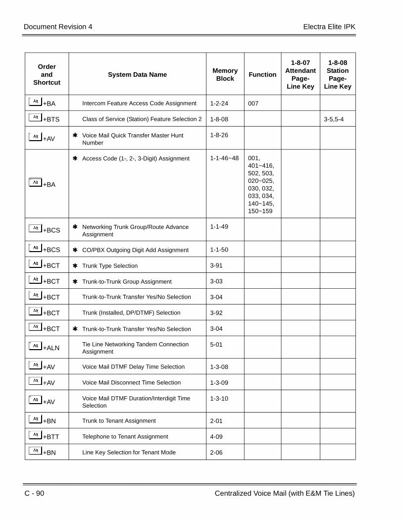
C - 90 Centralized Voice Mail (with E&M Tie Lines)
___________________________________________________________________________________
___________________________________________________________________________________Document Revision 4 Electra Elite IPK
+BA Intercom Feature Access Code Assignment 1-2-24 007
+BTS Class of Service (Station) Feature Selection 2 1-8-08 3-5,5-4
+AV Voice Mail Quick Transfer Master Hunt Number
1-8-26
+BA
Access Code (1-, 2-, 3-Digit) Assignment 1-1-46~48 001, 401~416,502, 503,020~025,030, 032,033, 034,140~145,150~159
+BCS Networking Trunk Group/Route Advance Assignment
1-1-49
+BCS CO/PBX Outgoing Digit Add Assignment 1-1-50
+BCT Trunk Type Selection 3-91
+BCT Trunk-to-Trunk Group Assignment 3-03
+BCT Trunk-to-Trunk Transfer Yes/No Selection 3-04
+BCT Trunk (Installed, DP/DTMF) Selection 3-92
+BCT Trunk-to-Trunk Transfer Yes/No Selection 3-04
+ALNTie Line Networking Tandem Connection Assignment
5-01
+AV Voice Mail DTMF Delay Time Selection 1-3-08
+AV Voice Mail Disconnect Time Selection 1-3-09
+AVVoice Mail DTMF Duration/Interdigit Time Selection
1-3-10
+BN Trunk to Tenant Assignment 2-01
+BTT Telephone to Tenant Assignment 4-09
+BN Line Key Selection for Tenant Mode 2-06
Orderand
ShortcutSystem Data Name
Memory Block
Function
1-8-07Attendant
Page-Line Key
1-8-08StationPage-
Line Key

Electra Elite IPK Document Revision 4
Features and Specifications Manual C - 91
___________________________________________________________________________________
___________________________________________________________________________________
+BTM Line Key Selection for Telephone Mode 4-12
+BCT DIT Assignment 3-42
+BCT ANA Assignment 3-43
+BCT DIT/ANA Delay Answer Time Selection 3-61
+BCT DIT Tenant Assignment 3-62
+BCT DIT Weekend Mode Selection 3-63
+BCT DIT Night Mode Delay Answer Selection 3-64
+BTTCall forward - Busy Immediately/Delay Selection
4-42
+BM Call forward - No Answer Time Selection 1-2-22
+AC Station to Timer Class of Service 4-71
When the system is at default this Memory Block must be programmed for the feature to be used.
Orderand
ShortcutSystem Data Name
Memory Block
Function
1-8-07Attendant
Page-Line Key
1-8-08StationPage-
Line Key

C - 92 Centralized Voice Mail (with E&M Tie Lines)
___________________________________________________________________________________
___________________________________________________________________________________Document Revision 4 Electra Elite IPK
THIS PAGE INTENTIONALLY LEFT BLANK

Features and Specifications Manual C - 93
___________________________________________________________________________________
___________________________________________________________________________________
Class of Service C-19
FEATURE DESCRIPTION
Class of Service assigns and controls access to features. Various Class of Service combinations can be programmed. Stations are then assigned according to the features they can access.
SYSTEM AVAILABILITY
Terminal Type:
All Stations
Required Components:
None
ENHANCEMENT(S)
Release 2000:
With R2000 or higher, The following assignments are added:
Call Monitor (Originate)
Call Monitor (Receive)
Release 3000:
With R3000 or higher, The following assignments are added:
Save Caller ID Missed Calls
Send Caller ID Information to Single Line Telephones
OPERATING PROCEDURES
None

C - 94 Class of Service
___________________________________________________________________________________
___________________________________________________________________________________Document Revision 4 Electra Elite IPK
SERVICE CONDITIONS
General:
Each Class of Service provides 16 different Classes.
The following Attendant features can be allowed/denied in each class for Class of Service assignment (Attendant) Feature Selection 1:
FeaturesDefault Values (Station Ports
01 & 02)
Night Mode Switching (System-Wide) Allow
Night Mode Switching (Tenant) Allow
System Speed Dial Programming Allow
Automatic Trunk-to-Trunk Transfer (Set/Reset) and Programming of Outgoing Numbers
Allow
Automated Attendant Mode/DISA Mode (Set/Reset) Allow
Timed Alarm (Set/Reset) for Single Line Telephones (From Attendant
Allow
Call Forward – All Call (Set/Reset) from Destination StationCall forward CAR extensionsCall forward BNA
Allow
System-Wide Reset of Timed Alarm, Call Forward – All Call, Do Not Disturb, Customized Message, and Callback Request
Deny
Cancel Station Lockout and Default Password for Another station
Allow
DISA Password Cancel Allow
DISA Password Confirmation Allow
Automated Attendant Weekend Mode (Set/Reset) per Tenant
Allow
Forced Account Code Programming Allow
Terminal Exchange Mode Set Allow
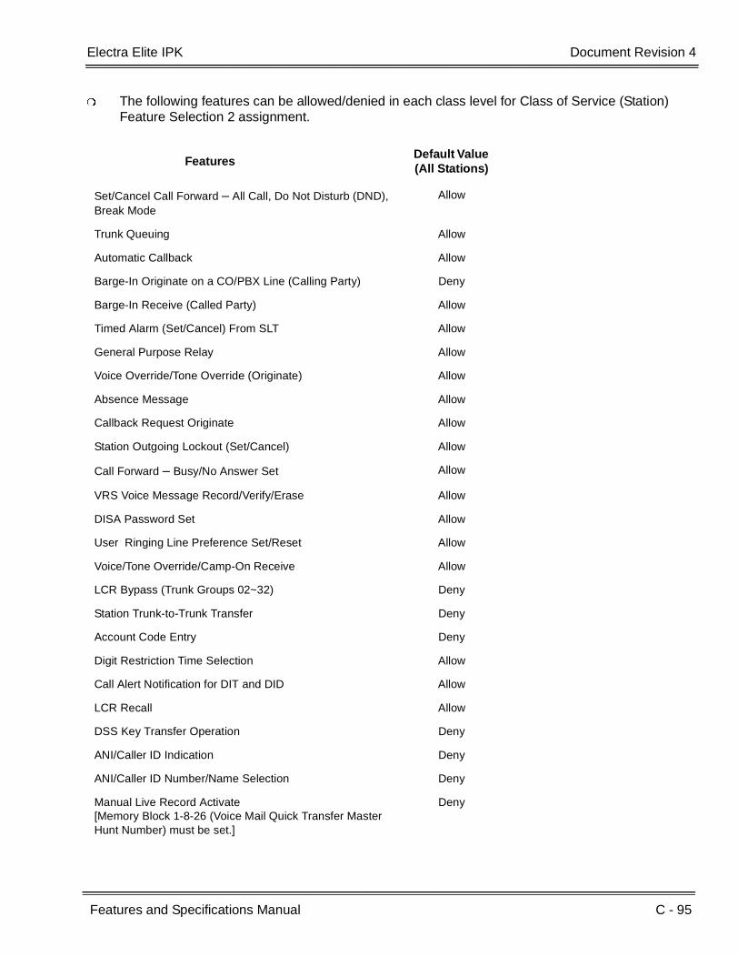
Electra Elite IPK Document Revision 4
Features and Specifications Manual C - 95
___________________________________________________________________________________
___________________________________________________________________________________
The following features can be allowed/denied in each class level for Class of Service (Station) Feature Selection 2 assignment.
FeaturesDefault Value (All Stations)
Set/Cancel Call Forward – All Call, Do Not Disturb (DND), Break Mode
Allow
Trunk Queuing Allow
Automatic Callback Allow
Barge-In Originate on a CO/PBX Line (Calling Party) Deny
Barge-In Receive (Called Party) Allow
Timed Alarm (Set/Cancel) From SLT Allow
General Purpose Relay Allow
Voice Override/Tone Override (Originate) Allow
Absence Message Allow
Callback Request Originate Allow
Station Outgoing Lockout (Set/Cancel) Allow
Call Forward – Busy/No Answer Set Allow
VRS Voice Message Record/Verify/Erase Allow
DISA Password Set Allow
User Ringing Line Preference Set/Reset Allow
Voice/Tone Override/Camp-On Receive Allow
LCR Bypass (Trunk Groups 02~32) Deny
Station Trunk-to-Trunk Transfer Deny
Account Code Entry Deny
Digit Restriction Time Selection Allow
Call Alert Notification for DIT and DID Allow
LCR Recall Allow
DSS Key Transfer Operation Deny
ANI/Caller ID Indication Deny
ANI/Caller ID Number/Name Selection Deny
Manual Live Record Activate[Memory Block 1-8-26 (Voice Mail Quick Transfer Master Hunt Number) must be set.]
Deny
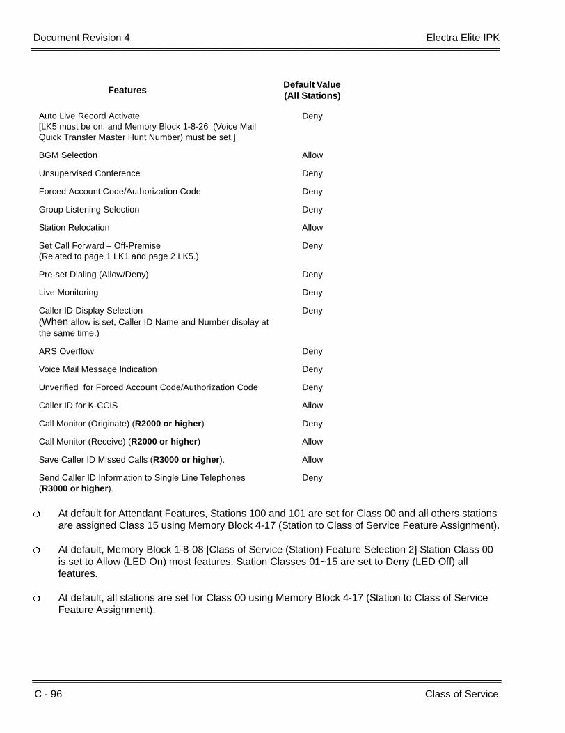
C - 96 Class of Service
___________________________________________________________________________________
___________________________________________________________________________________Document Revision 4 Electra Elite IPK
At default for Attendant Features, Stations 100 and 101 are set for Class 00 and all others stations are assigned Class 15 using Memory Block 4-17 (Station to Class of Service Feature Assignment).
At default, Memory Block 1-8-08 [Class of Service (Station) Feature Selection 2] Station Class 00 is set to Allow (LED On) most features. Station Classes 01~15 are set to Deny (LED Off) all features.
At default, all stations are set for Class 00 using Memory Block 4-17 (Station to Class of Service Feature Assignment).
Auto Live Record Activate [LK5 must be on, and Memory Block 1-8-26 (Voice Mail Quick Transfer Master Hunt Number) must be set.]
Deny
BGM Selection Allow
Unsupervised Conference Deny
Forced Account Code/Authorization Code Deny
Group Listening Selection Deny
Station Relocation Allow
Set Call Forward – Off-Premise(Related to page 1 LK1 and page 2 LK5.)
Deny
Pre-set Dialing (Allow/Deny) Deny
Live Monitoring Deny
Caller ID Display Selection (When allow is set, Caller ID Name and Number display at the same time.)
Deny
ARS Overflow Deny
Voice Mail Message Indication Deny
Unverified for Forced Account Code/Authorization Code Deny
Caller ID for K-CCIS Allow
Call Monitor (Originate) (R2000 or higher) Deny
Call Monitor (Receive) (R2000 or higher) Allow
Save Caller ID Missed Calls (R3000 or higher). Allow
Send Caller ID Information to Single Line Telephones (R3000 or higher).
Deny
FeaturesDefault Value (All Stations)
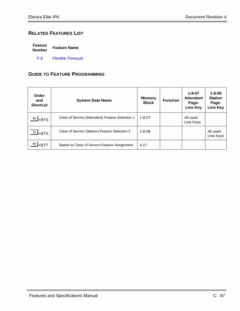
Electra Elite IPK Document Revision 4
Features and Specifications Manual C - 97
___________________________________________________________________________________
___________________________________________________________________________________
RELATED FEATURES LIST
GUIDE TO FEATURE PROGRAMMING
Feature Number
Feature Name
F-6 Flexible Timeouts
Orderand
ShortcutSystem Data Name
Memory Block
Function
1-8-07Attendant
Page-Line Key
1-8-08StationPage-
Line Key
+BTSClass of Service (Attendant) Feature Selection 1 1-8-07 All used
Line Keys
+BTSClass of Service (Station) Feature Selection 2 1-8-08 All used
Line Keys
+BTT Station to Class of Service Feature Assignment 4-17

C - 98 Class of Service
___________________________________________________________________________________
___________________________________________________________________________________Document Revision 4 Electra Elite IPK
THIS PAGE INTENTIONALLY LEFT BLANK
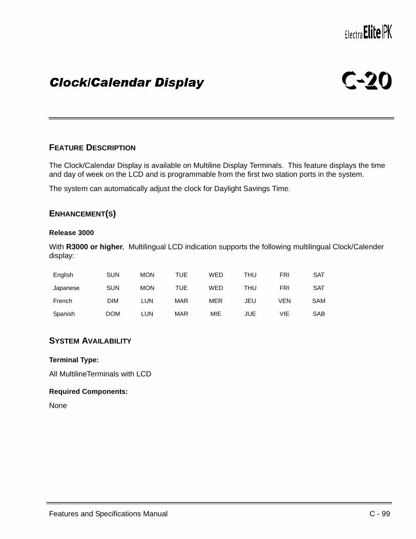
Features and Specifications Manual C - 99
___________________________________________________________________________________
___________________________________________________________________________________
Clock/Calendar Display C-20
FEATURE DESCRIPTION
The Clock/Calendar Display is available on Multiline Display Terminals. This feature displays the time and day of week on the LCD and is programmable from the first two station ports in the system.
The system can automatically adjust the clock for Daylight Savings Time.
ENHANCEMENT(S)
Release 3000
With R3000 or higher, Multilingual LCD indication supports the following multilingual Clock/Calender display:
SYSTEM AVAILABILITY
Terminal Type:
All MultilineTerminals with LCD
Required Components:
None
English SUN MON TUE WED THU FRI SAT
Japanese SUN MON TUE WED THU FRI SAT
French DIM LUN MAR MER JEU VEN SAM
Spanish DOM LUN MAR MIE JUE VIE SAB
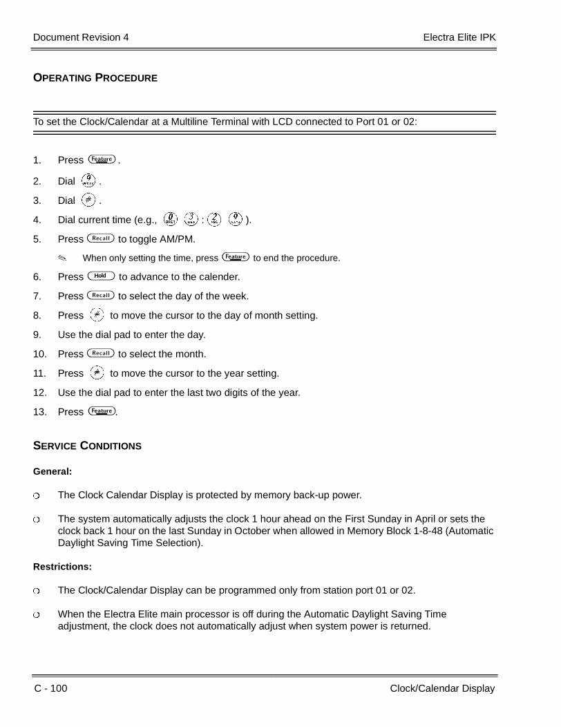
C - 100 Clock/Calendar Display
___________________________________________________________________________________
___________________________________________________________________________________Document Revision 4 Electra Elite IPK
OPERATING PROCEDURE
To set the Clock/Calendar at a Multiline Terminal with LCD connected to Port 01 or 02:
1. Press A .
2. Dial I.
3. Dial L.
4. Dial current time (e.g., KC:BI).
5. Press C to toggle AM/PM.
When only setting the time, press A to end the procedure.
6. Press H to advance to the calender.
7. Press C to select the day of the week.
8. Press L to move the cursor to the day of month setting.
9. Use the dial pad to enter the day.
10. Press C to select the month.
11. Press L to move the cursor to the year setting.
12. Use the dial pad to enter the last two digits of the year.
13. Press A .
SERVICE CONDITIONS
General:
The Clock Calendar Display is protected by memory back-up power.
The system automatically adjusts the clock 1 hour ahead on the First Sunday in April or sets the clock back 1 hour on the last Sunday in October when allowed in Memory Block 1-8-48 (Automatic Daylight Saving Time Selection).
Restrictions:
The Clock/Calendar Display can be programmed only from station port 01 or 02.
When the Electra Elite main processor is off during the Automatic Daylight Saving Time adjustment, the clock does not automatically adjust when system power is returned.

Electra Elite IPK Document Revision 4
Features and Specifications Manual C - 101
___________________________________________________________________________________
___________________________________________________________________________________
RELATED FEATURE LIST
GUIDE TO FEATURE PROGRAMMING
Feature Number
Feature Name
M-5 Multilingual LCD Indication
Orderand
ShortcutSystem Data Name
Memory Block
Function
1-8-07Attendant
Page-Line Key
1-8-08StationPage-
Line Key
+BM Time Display (12h/24h) Selection 1-8-04
+BM Automatic Daylight Saving Time Selection 1-8-48
+BTM Multilingual LCD Indication Selection 4-28

C - 102 Clock/Calendar Display
___________________________________________________________________________________
___________________________________________________________________________________Document Revision 4 Electra Elite IPK
THIS PAGE INTENTIONALLY LEFT BLANK

Features and Specifications Manual C - 103
___________________________________________________________________________________
___________________________________________________________________________________
Code Restriction C-21
FEATURE DESCRIPTION
Code Restriction for outgoing calls is based on the first eight digits dialed. Code Restriction denies outside calls based on number dialed over a trunk group and accommodates equal access to Other Common Carriers (OCCs) and CO Feature Codes. This eliminates unauthorized calls and configures system calling functions to provide cost control.
SYSTEM AVAILABILITY
Terminal Type:
All Stations
Required Components:
None
OPERATING PROCEDURES
When a station user attempts an outside call to a station that is code restricted, the following occurs:
1. The user goes off-hook, waits for internal dial tone, and dials a Trunk Access Code or goes off-hook on an outside line.
2. The user receives an outside dial tone, and dials a restricted telephone number.
3. A reorder tone is generated, and ERROR is displayed on terminals with an LCD.

C - 104 Code Restriction
___________________________________________________________________________________
___________________________________________________________________________________Document Revision 4 Electra Elite IPK
SERVICE CONDITIONS
General:
At default, the 14 programmable station classes are assigned as follows:
Using other common carriers (equal access) can be allowed or denied by the Code Restriction feature.
Code Restriction applies after CO Feature Code is dialed.
When using Code Restriction with LCR, Code Restriction is applied to the digits dialed by the system.
System Programming has 16 classes. Two of the 16 classes have fixed restrictions: Class 00 allows all outside calls and Class 15 restricts all outside calls.
Sixteen 8-Digit Matching tables can be assigned for each of the 14 remaining classes. Each 8-Digit Matching table allows eight digits to be entered.
The Recall key or a Drop key cannot be used to bypass Code Restriction. (A Drop key is provided by programming a Feature Access Code on a Feature Access key or One-Touch key.)
RELATED FEATURES LIST
Class 01: Deny 0 and 1+ calls
Class 02: Deny 0 and 1+ calls, Allow 1-800, 1-888, 1-877 calls
Class 03: Deny 0, 1+, and 976 calls, Allow 1-800, 1-888, 1-877 calls
Class 04: Deny only 1+ calls, Allow 1-800, 1-888, and 1-877 calls
Class 05~14: Allow only 911 calls
All classes deny OCC calls. Classes 01~04 allow local calls.
Feature Number
Feature Name
A-14 Attendant Station Outgoing Lockout
A-16 Authorization Code
C-22 CO/PBX, Tie Line Digit Restriction
S-19 Station Outgoing Lockout
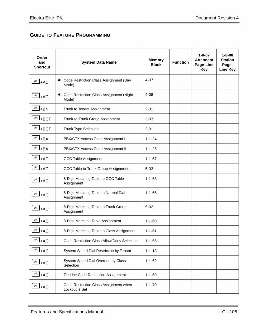
Electra Elite IPK Document Revision 4
Features and Specifications Manual C - 105
___________________________________________________________________________________
___________________________________________________________________________________
GUIDE TO FEATURE PROGRAMMING
Orderand
ShortcutSystem Data Name
Memory Block
Function
1-8-07AttendantPage-Line
Key
1-8-08StationPage-
Line Key
+AC Code Restriction Class Assignment (Day Mode)
4-07
+AC Code Restriction Class Assignment (Night Mode)
4-08
+BN Trunk to Tenant Assignment 2-01
+BCT Trunk-to-Trunk Group Assignment 3-03
+BCT Trunk Type Selection 3-91
+BA PBX/CTX Access Code Assignment I 1-1-24
+BA PBX/CTX Access Code Assignment II 1-1-25
+AC OCC Table Assignment 1-1-67
+AC OCC Table to Trunk Group Assignment 5-03
+AC8-Digit Matching Table to OCC Table Assignment
1-1-68
+AC8-Digit Matching Table to Normal Dial Assignment
1-1-66
+AC8-Digit Matching Table to Trunk Group Assignment
5-02
+AC 8-Digit Matching Table Assignment 1-1-60
+AC 8-Digit Matching Table to Class Assignment 1-1-61
+AC Code Restriction Class Allow/Deny Selection 1-1-65
+AC System Speed Dial Restriction by Tenant 1-1-18
+ACSystem Speed Dial Override by Class Selection
1-1-62
+AC Tie Line Code Restriction Assignment 1-1-69
+ACCode Restriction Class Assignment when Lockout is Set
1-1-70
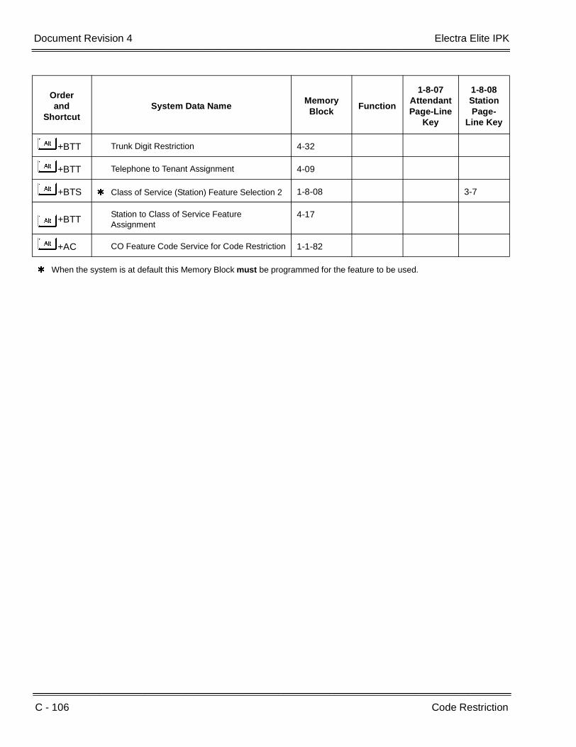
C - 106 Code Restriction
___________________________________________________________________________________
___________________________________________________________________________________Document Revision 4 Electra Elite IPK
+BTT Trunk Digit Restriction 4-32
+BTT Telephone to Tenant Assignment 4-09
+BTS Class of Service (Station) Feature Selection 2 1-8-08 3-7
+BTTStation to Class of Service Feature Assignment
4-17
+AC CO Feature Code Service for Code Restriction 1-1-82
When the system is at default this Memory Block must be programmed for the feature to be used.
Orderand
ShortcutSystem Data Name
Memory Block
Function
1-8-07AttendantPage-Line
Key
1-8-08StationPage-
Line Key

Features and Specifications Manual C - 107
___________________________________________________________________________________
___________________________________________________________________________________
CO/PBX, Tie Line Digit Restriction C-22
FEATURE DESCRIPTION
CO/PBX, Tie Line Digit Restriction eliminates unauthorized calls by restricting the number of digits that can be dialed from a station on an outside line.
SYSTEM AVAILABILITY
Terminal Type:
All stations
Required Components:
None
OPERATING PROCEDURES
None
SERVICE CONDITIONS
General:
Trunk Digit Restriction applies to all CO/PBX lines.
Digits 0~9, , and # are counted as digits dialed; pauses are not counted.
To reset the digit counter, the outside line must be released.
Press the Recall or Drop key to reset the digit counter. (A Drop key is provided by programming a Feature Access Code on a Feature Access key or One-Touch key.)
Press Feature Access or One-Touch key (programmed for hookflash) to reset the digit counter.
When the outside line is put on hold, the digit counter retains the number of digits dialed. When a station user picks up the held line, digit counting continues.
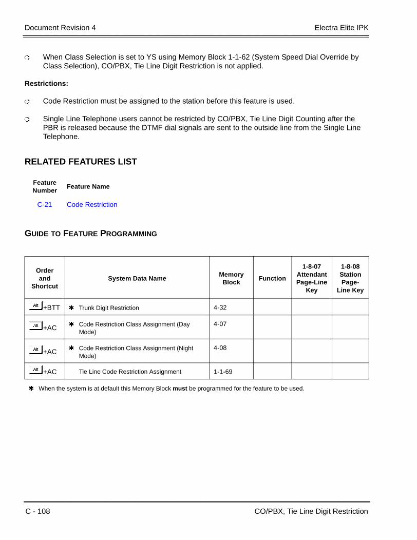
C - 108 CO/PBX, Tie Line Digit Restriction
___________________________________________________________________________________
___________________________________________________________________________________Document Revision 4 Electra Elite IPK
When Class Selection is set to YS using Memory Block 1-1-62 (System Speed Dial Override by Class Selection), CO/PBX, Tie Line Digit Restriction is not applied.
Restrictions:
Code Restriction must be assigned to the station before this feature is used.
Single Line Telephone users cannot be restricted by CO/PBX, Tie Line Digit Counting after the PBR is released because the DTMF dial signals are sent to the outside line from the Single Line Telephone.
RELATED FEATURES LIST
GUIDE TO FEATURE PROGRAMMING
Feature Number
Feature Name
C-21 Code Restriction
Orderand
ShortcutSystem Data Name
Memory Block
Function
1-8-07AttendantPage-Line
Key
1-8-08StationPage-
Line Key
+BTT Trunk Digit Restriction 4-32
+AC Code Restriction Class Assignment (Day Mode)
4-07
+AC Code Restriction Class Assignment (Night Mode)
4-08
+AC Tie Line Code Restriction Assignment 1-1-69
When the system is at default this Memory Block must be programmed for the feature to be used.
Features and Specifications Manual C - 109
___________________________________________________________________________________
___________________________________________________________________________________
CO Message Waiting Indication C-23
FEATURE DESCRIPTION
This feature provides a Message Waiting indication when Voice Mail from the Central Office is used. The CO provides this feature using Visual Message Waiting Indication (VMWI) standards.
VMWI visually indicates to a user that a message is present in their voice mail box. When VMWI is provided, the Electra Elite IPK provides a flashing LED on a line key assigned with the trunk appearance.
The VMWI standard supported by the Electra Elite IPK includes:
Type 1 Caller ID, FSK without power ringing using the MDMF protocol
Type 1 Caller ID, FSK without power ringing using the SDMF protocol
R4000 or higher is required to support SDMF protocol. For additional information related to these protocols refer to the TIA Standard ANSI/TIA-777-A-2003.
SYSTEM AVAILABILITY
Terminal Type:
All Multiline Terminals
Required Software:
R2000 or higher
Required Components:
COIB(4)/(8)-U30 ETU
OPERATING PROCEDURES

C - 110 CO Message Waiting Indication
___________________________________________________________________________________
___________________________________________________________________________________Document Revision 4 Electra Elite IPK
To program the System Speed Dial buffer from an Attendant Position:
1. Press A .
2. Press B .
3. Dial Speed Dial buffer to be programmed (KK~ GI or KKK~ III).
4. Dial the Trunk or Trunk Group Access Code (four-digit maximum).
5. Dial the desired telephone number.
6. Press H , and use the dial pad to enter the name (if desired) using the Character Code Table.
- OR -
7. Press A .
The System Speed Dial buffer must be programmed for the telephone number associated with the CO/PBX line.
To program the CO Message Waiting Indication Callback Speed Dial number from an Attendant Position:
1. Press A .
2. Dial BH.
3. Press CO/PBX line key with VMWI feature.
4. Dial System Speed Dial buffer (KK~ GI or KKK~ III).
5. Press A .
To confirm the CO Message Waiting Indication Callback Speed Dial number from an Attendant Position:
1. Press A .
2. Dial BI.
3. Press CO/PBX Line key.
4. Display indicates XX>[YY] for 10 seconds.
XX is the Trunk Number. YY is the System Speed Dial buffer used.
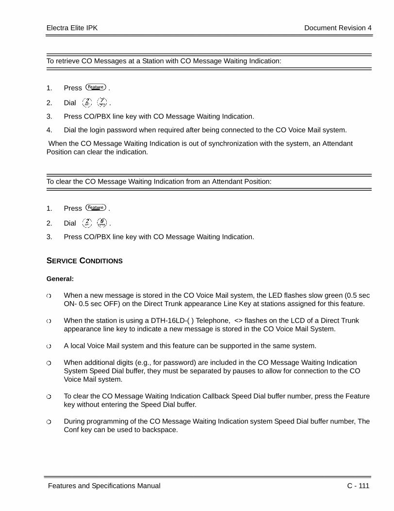
Electra Elite IPK Document Revision 4
Features and Specifications Manual C - 111
___________________________________________________________________________________
___________________________________________________________________________________
To retrieve CO Messages at a Station with CO Message Waiting Indication:
1. Press A .
2. Dial BG.
3. Press CO/PBX line key with CO Message Waiting Indication.
4. Dial the login password when required after being connected to the CO Voice Mail system.
When the CO Message Waiting Indication is out of synchronization with the system, an Attendant Position can clear the indication.
To clear the CO Message Waiting Indication from an Attendant Position:
1. Press A .
2. Dial BK.
3. Press CO/PBX line key with CO Message Waiting Indication.
SERVICE CONDITIONS
General:
When a new message is stored in the CO Voice Mail system, the LED flashes slow green (0.5 sec ON- 0.5 sec OFF) on the Direct Trunk appearance Line Key at stations assigned for this feature.
When the station is using a DTH-16LD-( ) Telephone, <> flashes on the LCD of a Direct Trunk appearance line key to indicate a new message is stored in the CO Voice Mail System.
A local Voice Mail system and this feature can be supported in the same system.
When additional digits (e.g., for password) are included in the CO Message Waiting Indication System Speed Dial buffer, they must be separated by pauses to allow for connection to the CO Voice Mail system.
To clear the CO Message Waiting Indication Callback Speed Dial buffer number, press the Feature key without entering the Speed Dial buffer.
During programming of the CO Message Waiting Indication system Speed Dial buffer number, The Conf key can be used to backspace.
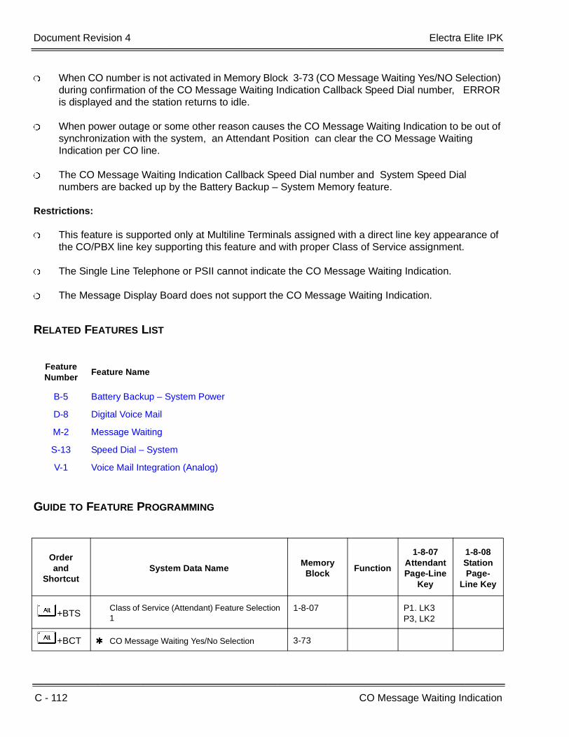
C - 112 CO Message Waiting Indication
___________________________________________________________________________________
___________________________________________________________________________________Document Revision 4 Electra Elite IPK
When CO number is not activated in Memory Block 3-73 (CO Message Waiting Yes/NO Selection) during confirmation of the CO Message Waiting Indication Callback Speed Dial number, ERROR is displayed and the station returns to idle.
When power outage or some other reason causes the CO Message Waiting Indication to be out of synchronization with the system, an Attendant Position can clear the CO Message Waiting Indication per CO line.
The CO Message Waiting Indication Callback Speed Dial number and System Speed Dial numbers are backed up by the Battery Backup – System Memory feature.
Restrictions:
This feature is supported only at Multiline Terminals assigned with a direct line key appearance of the CO/PBX line key supporting this feature and with proper Class of Service assignment.
The Single Line Telephone or PSII cannot indicate the CO Message Waiting Indication.
The Message Display Board does not support the CO Message Waiting Indication.
RELATED FEATURES LIST
GUIDE TO FEATURE PROGRAMMING
Feature Number
Feature Name
B-5 Battery Backup – System Power
D-8 Digital Voice Mail
M-2 Message Waiting
S-13 Speed Dial – System
V-1 Voice Mail Integration (Analog)
Orderand
ShortcutSystem Data Name
Memory Block
Function
1-8-07AttendantPage-Line
Key
1-8-08StationPage-
Line Key
+BTSClass of Service (Attendant) Feature Selection 1
1-8-07 P1. LK3P3, LK2
+BCT CO Message Waiting Yes/No Selection 3-73

Electra Elite IPK Document Revision 4
Features and Specifications Manual C - 113
___________________________________________________________________________________
___________________________________________________________________________________
+BTTStation to Class of Service Feature Assignment
4-17
+BTT CO Message Waiting Indication Assignment 4-69
When the system is at default this Memory Block must be programmed for the feature to be used.
Orderand
ShortcutSystem Data Name
Memory Block
Function
1-8-07AttendantPage-Line
Key
1-8-08StationPage-
Line Key
C - 114 CO Message Waiting Indication
___________________________________________________________________________________
___________________________________________________________________________________Document Revision 4 Electra Elite IPK
THIS PAGE INTENTIONALLY LEFT BLANK

Features and Specifications Manual C - 115
___________________________________________________________________________________
___________________________________________________________________________________
Computer Telephony Integration (CTI) C-24
FEATURE DESCRIPTION
CTI integrates computers and telephones to access sophisticated communication services using telephone lines. The Telephony Application Programming Interface (TAPI) supports speech and data transmissions, allows a variety of attachment devices, and supports complex functions such as conference calls, call waiting, and voice mail. Through TAPI, all elements of telephone usage, including simple dial and voice calls, can be controlled by Windows 95 and higher Windows versions.
CTI is implemented using a Computer Telephony Adapter (CT(A)-R/CTA-U Unit) or CT(U)-R/CTU(S)-U Unit.
The CT(A)-R Unit can be attached to any DTH/DTR terminal except the DTR-2DT-1 TEL. The CTA-U Unit can be attached to any DTU/DTP terminal except the DTP-2DT-1 TEL. Either unit provides a serial RS-232 connector to the PC that allows TAPI applications to control telephony features of the KSU.
The CT(U)-R Unit can be attached to any DTH/DTR terminal except the DTR-2DT-1 TEL. The CTU(S)-U Unit can be attached to any DTU/DTP terminal except the DTP-2DT-1 TEL. Either unit provides a Universal Serial Bus (USB) connection to the PC that allows TAPI applications to control telephony features on the KSU.
SYSTEM AVAILABILITY
Terminal Type:
Any DTH/DTR terminal except the DTR-2DR-1 TEL
Any DTU/DTP terminal except the DTP-2DT-1 TEL
Required Components:
For DTH/DTR terminals:
CT(A)-R Unit
CT(U)-R Unit
For DTU/DTP terminals:
CTA-U Unit
CTU(S)-U Unit
C - 116 Computer Telephony Integration (CTI)
___________________________________________________________________________________
___________________________________________________________________________________Document Revision 4 Electra Elite IPK
OPERATING PROCEDURES
Refer to the CTI product literature.
SERVICE CONDITIONS
General:
The CT(A)-R Unit connects to the bottom of any DTH/DTR Multiline Terminal except DTR-2DT-1 TEL. The CTA-U Unit connects to the bottom of any DTU/DTP Multiline Terminal except DTP-2DT-1 TEL.
The CT(U)-R Unit connects to the bottom of any DTH/DTR Multiline Terminal except DTR-2DT-1 TEL. The CTU(S)-U Unit connects to the bottom of any DTU/DTP Multiline Terminal except DTP-2DT-1 TEL.
Restrictions:
When 5-, 6-, or 7-digit station numbers are used, this feature is not available.

Features and Specifications Manual C - 117
___________________________________________________________________________________
___________________________________________________________________________________
Consecutive Speed Dial C-25
FEATURE DESCRIPTION
Consecutive Speed Dial allows using System Speed Dial, Station Speed Dial, and manual dialing for all stations consecutively. Simplified dialing sequences permit easier access to secondary common carriers, credit card verification, and other applications that require entry of authorization codes or customer numbers.
SYSTEM AVAILABILITY
Terminal Type:
All Multiline Terminals
Required Components:
None
OPERATING PROCEDURES
To use this feature at a Multiline Terminal:
1. Lift the handset or press E . Wait for dial tone.
2. Use any combination of manual dialing, Station Speed Dial, or System Speed Dial.

C - 118 Consecutive Speed Dial
___________________________________________________________________________________
___________________________________________________________________________________Document Revision 4 Electra Elite IPK
SERVICE CONDITIONS
General:
A maximum of 24 digits can be stored in Multiline Terminal Speed Dial buffers. Pause, hookflash, #, and count as digits when stored in speed dial buffer.
When the system is programmed as a Key Function (KF) system, Consecutive Speed Dial cannot be used from internal dial tone but can be used from a direct CO line appearance.
When using Single Line Telephones, only manual dialing sequences can follow a Station or System Speed Dial sequence.

Features and Specifications Manual C - 119
___________________________________________________________________________________
___________________________________________________________________________________
Cordless Telephone Connection C-26
FEATURE DESCRIPTION
Using an AP(R)/AP(A)-R Unit for a DTH/DTR telephone, or an APR/APA-U Unit for a DTU/DTP telephone, a cordless telephone (2500-type) can be connected to a Multiline Terminal. System Programming defines whether or not the cordless telephone rings when calls are directed to the Multiline Terminal associated with it; however, only the AP(R)-R or the APR-U Unit provides ringing.
The SLI(4)/(8)-U( ) ETU and the SLT(1)-U( ) ADP also supports cordless telephones, but this feature refers to Multiline Terminal cordless connection.
SYSTEM AVAILABILITY
Terminal Type:
Any DTH/DTR terminal with an AP(A)-R or AP(R)-R Unit except the DTR-2DT-1 TEL
Any DTU/DTP terminal with an APA-U or APR-U Unit except the DTP-2ST-1 TEL
Required Components:
2500-type cordless Single Line Telephone
OPERATING PROCEDURES
To make a call using a cordless Single Line Telephone:
1. Go off-hook.
2. Dial the station number or dial the Trunk Access Code and telephone number.
C - 120 Cordless Telephone Connection
___________________________________________________________________________________
___________________________________________________________________________________Document Revision 4 Electra Elite IPK
To answer a call using a cordless Single Line Telephone:
When the Multiline Terminal is ringing, the incoming call can be answered by the cordless Single Line Telephone user by going off-hook, when ringing line preference is assigned for the Multiline Terminal.
To transfer a call from a cordless Single Line Telephone to its associated Multiline Terminal:
1. Multiline Terminal user goes off-hook.
2. Single Line Telephone user goes on-hook (at this time, the call is automatically connected to the Multiline Terminal).
To transfer a call from a Multiline Terminal to its associated cordless Single Line Telephone:
1. Single Line Telephone user goes off-hook (at this time, the call is automatically connected to the Single Line Telephone).
2. Multiline Terminal user goes on-hook.
To use Hookflash
Refer to operation for Single Line Telephone Access.
SERVICE CONDITIONS
Restrictions:
A voice announced internal call to the Multiline Terminal does not ring the cordless telephone.
Only one cordless Single Line Telephone can be connected to an APR-U, APA-U, AP(R)-R, or AP(A)-R Unit.
When CO Prime Line is assigned to the associated Multiline Terminal, internal dial tone cannot be transferred to the cordless telephone.
The cordless telephone requires a PBR circuit while dialing. When all PBR circuits are busy, a busy tone is heard when the phone goes off-hook.
Electra Elite IPK Document Revision 4
Features and Specifications Manual C - 121
___________________________________________________________________________________
___________________________________________________________________________________
Depending on your environment, the maximum number of cordless devices used without interference varies.
General:
This feature works with 2500-type cordless Single Line Telephones.
Disconnect signal, DTMF sending (to cordless telephone), Message Wait, transferring calls, placing calls on hold, hookswitch signals, and DP cordless telephones are not supported for cordless telephones.
A maximum of 120 AP(A)-R, AP(R)-R, APA-U, or APR-U Units can be installed in Multiline Terminals on the Electra Elite IPK Expanded Port system. The maximum for the Electra Elite IPK Basic Port system is 32.
The Multiline Terminal user and the associated cordless telephone user cannot talk to each other.
An AP(A)-R, AP(R)-R, APA-U, or APR-U Unit with hookflash enabled follows the same operating procedures as a Single Line Terminal connected to an SLI(8)-U( ) ETU.
The Multiline Terminal LCD displays normal information for Multiline Terminal when a cordless terminal is used.
When the Multiline Terminal user goes off-hook before the cordless Single Line Telephone user, a PBR circuit is not connected for the cordless Single Line Telephone.
The ring pattern for the cordless telephone can be selected by a jumper switch in the AP(R)-R or APR-U Units. The patterns are:
1 second ON/2 seconds OFF
2 seconds ON/4 seconds OFF
The cordless telephone must be installed within 10 feet of the AP(R)-R Unit or APR-U Unit.
RELATED FEATURES LIST
Feature Number
Feature Name
A-7 Ancillary Device Connection
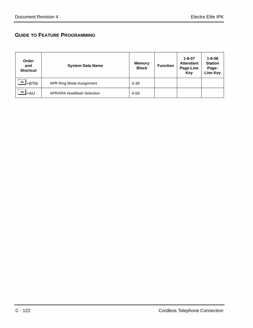
C - 122 Cordless Telephone Connection
___________________________________________________________________________________
___________________________________________________________________________________Document Revision 4 Electra Elite IPK
GUIDE TO FEATURE PROGRAMMING
Orderand
ShortcutSystem Data Name
Memory Block
Function
1-8-07AttendantPage-Line
Key
1-8-08StationPage-
Line Key
+BTM APR Ring Mode Assignment 4-39
+AU APR/APA Hookflash Selection 4-59

Features and Specifications Manual C - 123
___________________________________________________________________________________
___________________________________________________________________________________
Customized Message C-27
FEATURE DESCRIPTION
A station with Do Not Disturb set can select a Customized Message that is displayed at any other Multiline Display Terminal when an internal call is made to that station. The message (10 messages can be programmed) remains displayed on the LCD of the Multiline Terminal where the message was set.
SYSTEM AVAILABILITY
Terminal Type:
All Multiline Terminals equipped with an LCD
Required Components:
None
OPERATING PROCEDURES
To set a message at a Multiline Terminal:
1. Press A .
2. Dial Access Code GK.
3. PressJto select a message. Continue pressingJto scroll through the possible messages.
4. Press L, and enter date and time. (Date and time are optional.)
5. Press A .
6. Set Do Not Disturb ( A FK A ).
C - 124 Customized Message
___________________________________________________________________________________
___________________________________________________________________________________Document Revision 4 Electra Elite IPK
To receive a message at a Multiline Terminal with LCD:
1. Lift the handset, and wait for dial tone.
2. Dial the desired station number that has Customized Message set.
3. A message is received on the LCD from the station that was called.
To cancel a message at a Multiline Terminal:
1. Press A .
2. Dial GI.
3. Press A .
SERVICE CONDITIONS
General:
Six messages are provided in default. All 10 can be programmed.
Default messages are as follows:
DO NOT DISTURB
MEETING
BUSINESS TRIP
NOT IN
WITH GUEST
OUT OF OFFICE
The message remains on the LCD where the message was set.
When this feature is set, the Feature LED flashes.
When calling a station in Do Not Disturb mode, a message displays on the caller terminal. Three seconds later, the return date and time are displayed.
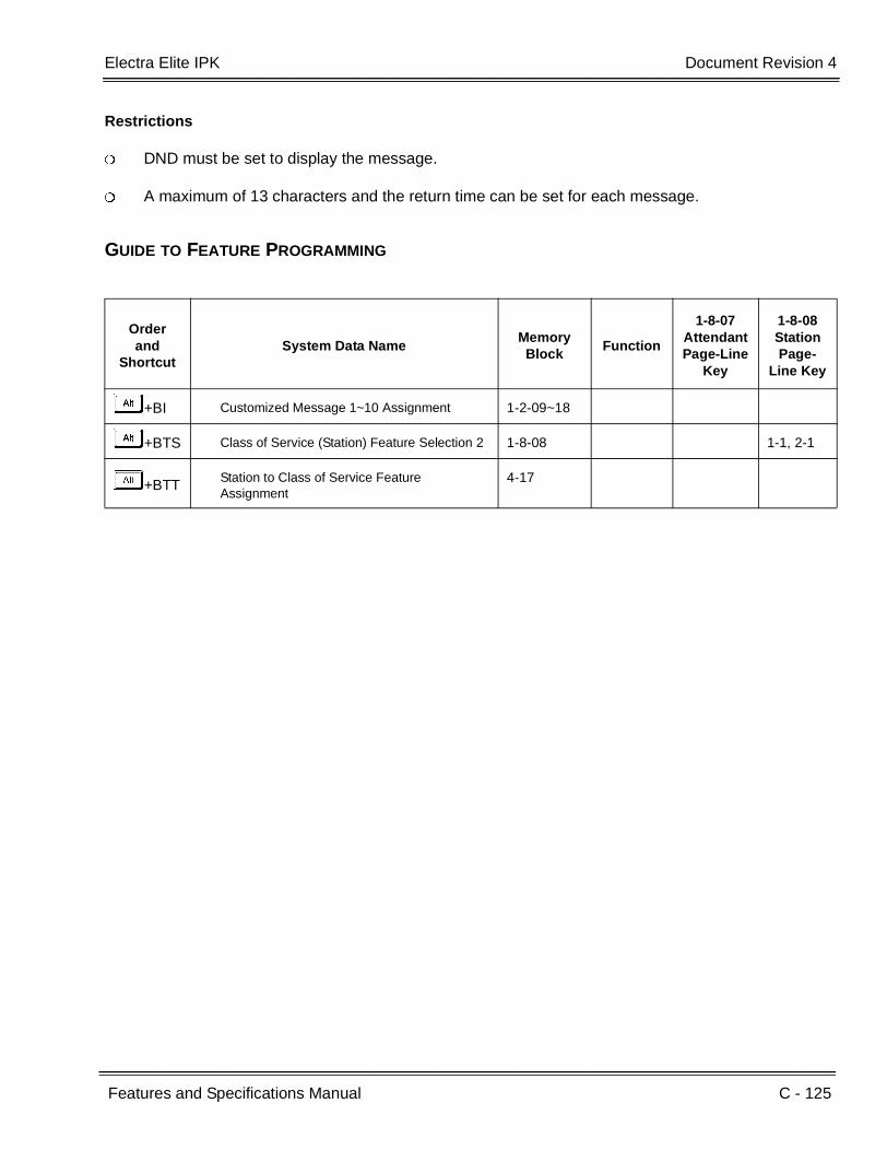
Electra Elite IPK Document Revision 4
Features and Specifications Manual C - 125
___________________________________________________________________________________
___________________________________________________________________________________
Restrictions
DND must be set to display the message.
A maximum of 13 characters and the return time can be set for each message.
GUIDE TO FEATURE PROGRAMMING
Orderand
ShortcutSystem Data Name
Memory Block
Function
1-8-07AttendantPage-Line
Key
1-8-08StationPage-
Line Key
+BI Customized Message 1~10 Assignment 1-2-09~18
+BTS Class of Service (Station) Feature Selection 2 1-8-08 1-1, 2-1
+BTT Station to Class of Service Feature Assignment
4-17

C - 126 Customized Message
___________________________________________________________________________________
___________________________________________________________________________________Document Revision 4 Electra Elite IPK
THIS PAGE INTENTIONALLY LEFT BLANK
Features and Specifications Manual D - 1
___________________________________________________________________________________
___________________________________________________________________________________
Data Line Security D-1
FEATURE DESCRIPTION
Data Line Security protects any station port from receiving audible tones (such as Camp-On or Override) and denies a station from barging in while busy to prevent disruption of data transmission when using a modem or facsimile machine.
SYSTEM AVAILABILITY
Terminal Type:
All Stations
Required Components:
None
OPERATING PROCEDURE
None
SERVICE CONDITIONS
General:
When a Multiline Terminal is assigned for Data Line Security, Tone Override and call alert notification tone are not heard from the handset; however, Tone Override and call alert notification tone are sent and heard from the speaker when the Multiline Terminal is off-hook.
A Single Line Telephone connected to an SLI(8)-U( ) ETU or an SLT(1)-U( ) ADP, with Data Line Security assigned, rings 1 second ON/2 seconds OFF for any ringing or transferred call.
The ringing pattern of a Single Line Telephone, connected to an AP(R)-R Unit or APR-U Unit, does not change when Data Line Security is assigned.
Data Line Security protects a station from Barge-In, even when Barge-In is allowed in Class of Service.
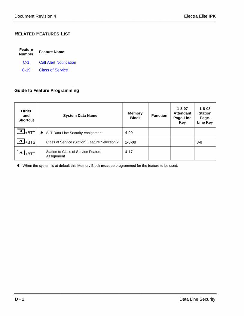
D - 2 Data Line Security
___________________________________________________________________________________
___________________________________________________________________________________Document Revision 4 Electra Elite IPK
RELATED FEATURES LIST
Guide to Feature Programming
Feature Number
Feature Name
C-1 Call Alert Notification
C-19 Class of Service
Orderand
ShortcutSystem Data Name
Memory Block
Function
1-8-07AttendantPage-Line
Key
1-8-08StationPage-
Line Key
+BTT SLT Data Line Security Assignment 4-90
+BTS Class of Service (Station) Feature Selection 2 1-8-08 3-8
+BTTStation to Class of Service Feature Assignment
4-17
When the system is at default this Memory Block must be programmed for the feature to be used.

Features and Specifications Manual D - 3
___________________________________________________________________________________
___________________________________________________________________________________
Delay Announcement D-2
FEATURE DESCRIPTION
Delay Announcement activates when an incoming call to an Automatic Call Distribution (ACD) or Uniform Call Distribution (UCD) group encounters all ACD/UCD stations busy or receives no answer within a programmed time. The call is queued and receives a recorded announcement after a programmed time. First and second Delay Announcements are available. The incoming call can be Direct Inward Termination (DIT/ANA), CO Ring Transfer, Automated Attendant Transfer, or DID/Tie line.
SYSTEM AVAILABILITY
Terminal Type:
Not applicable
Required Components:
VRS(4)-U( ) ETU is required for recorded announcement.
MIFA-U( ) ETU is required for UCD.
In the Electra Elite IPK system, MIFA-U( ) ETU and KMA(1.0)U are required for ACD.
OPERATING PROCEDURES
To record a Delay Announcement:
Refer to A-17 Automated Attendant for these instructions.
To process an incoming call:
1. An incoming call to an ACD/UCD group is received.
2. The First Delay Announcement answers the caller.

D - 4 Delay Announcement
___________________________________________________________________________________
___________________________________________________________________________________Document Revision 4 Electra Elite IPK
3. After the message, the call is connected to Music on Hold.
4. The Second Delay Announcement answers the caller after a programmed time.
5. After the message, the call is connected to Music on Hold again.
6. The Second Delay Announcement answers the caller again after a programmed time.
7. Steps 5 and 6 continue until the caller is answered by an Agent in the ACD/UCD group.
SERVICE CONDITIONS
General:
This feature is not used with Elite ACD Plus.
DIT/ANA, CO Ring transfers, Automated Attendant Transfers, and DID/Tie line calls must be directed to the ACD/UCD Pilot number to receive Delay Announcement.
When all Delay Announcement circuits are busy, the incoming caller continues to hear ringback tone or Music on Hold until a Delay Announcement circuit is available.
Each caller hears every announcement from the beginning.
When an ACD/UCD Agent is available, the caller is immediately connected to the Agent, even with a recorded announcement in progress.
This feature provides eight channels of two Delay Announcements. All four ACD/UCD groups share the two Delay Announcements.
The Delay Announcement feature is programmed per trunk.
Restrictions:
Two VRS(4)-U( ) ETUs can be installed in the Electra Elite IPK system.
Four calls can be connected to a single VRS(4)-U( ) ETU at the same moment.
When 5-, 6-, or 7-digit station numbers are used, this feature is not available.
RELATED FEATURES LIST
Feature Number
Feature Name
A-20 Automatic Call Distribution
U-3 Uniform Call Distribution (UCD)

Electra Elite IPK Document Revision 4
Features and Specifications Manual D - 5
___________________________________________________________________________________
___________________________________________________________________________________
GUIDE TO FEATURE PROGRAMMING
Orderand
ShortcutSystem Data Name
Memory Block
Function
1-8-07AttendantPage-Line
Key
1-8-08StationPage-
Line Key
+BS Card Interface Slot Assignment 7-1
+AR VRS Message Recording Time Selection 1-8-12
+AR VRS Message Function Assignment 1-8-13
+BA Access Code (1-, 2-, 3-Digit) Assignment 1-1-46/47/48
501
+BTS Class of Service (Station) Feature Selection 2 1-8-08 2-6
+BTTStation to Class of Service Feature Assignment
4-17
+AR Delay Announcement Assignment 3-41
+ARFirst Delay Announcement Start Time Selection
1-1-71
+AR First Delay Announcement Repeat Selection 1-1-72
+ARFirst to Second Delay Announcement Interval Time Selection
1-1-73
+ARSecond Delay Announcement Repeat Selection
1-1-74
+ARSecond Delay Announcement Repeat Interval Time Selection
1-1-75
When the system is at default this Memory Block must be programmed for the feature to be used.

D - 6 Delay Announcement
___________________________________________________________________________________
___________________________________________________________________________________Document Revision 4 Electra Elite IPK
THIS PAGE INTENTIONALLY LEFT BLANK

Features and Specifications Manual D - 7
___________________________________________________________________________________
___________________________________________________________________________________
Delayed Ringing D-3
FEATURE DESCRIPTION
Delayed Ringing allows programmed secondary answering positions to ring on incoming calls after a programmed time. This feature applies to CO/PBX lines, Secondary Incoming Extensions, and Call Arrival Keys.
SYSTEM AVAILABILITY
Terminal Type:
All Multiline Terminals
Required Components:
None
OPERATING PROCEDURES
To process an incoming call:
1. Receive delayed incoming ring.
2. Answer the call normally.
D - 8 Delayed Ringing
___________________________________________________________________________________
___________________________________________________________________________________Document Revision 4 Electra Elite IPK
SERVICE CONDITIONS
General:
The following incoming calls support Delayed Ringing:
Normal incoming CO/PBX ringing.
DIT/ANA, internal calls to Secondary Incoming Extension, and Call Arrival Key.
Incoming DID/Tie line call.
DID/Tie line/Automated Attendant call that converts to normal CO ringing call.
Incoming outside line that appears at the Attendant Add-On Console.
Single Line Telephone users can receive CO/PBX Delayed Ringing.
Delayed Ringing is provided to an off-hook terminal that is assigned for Off-Hook Ringing.
Single Line Telephones assigned Delay Ringing follow Station Hunting.
Use Memory Block 2-01 (Trunk to Tenant Assignment) to resolve Tenant Ringing conflicts by Trunk to Tenant Assignment. The lower number assigned tenant is used as the ringing control.
When a CO line is assigned DIT/ANA to a station that also has Delay Ringing assigned, the DIT/ANA does not occur until the Delay Ringing time expires.
RELATED FEATURES LIST
Feature Number
Feature Name
C-19 Class of Service
F-5 Flexible Ringing Assignment

Electra Elite IPK Document Revision 4
Features and Specifications Manual D - 9
___________________________________________________________________________________
___________________________________________________________________________________
GUIDE TO FEATURE PROGRAMMING
Orderand
ShortcutSystem Data Name
Memory Block
Function
1-8-07AttendantPage-Line
Key
1-8-08StationPage-
Line Key
+BN Trunk to Tenant Assignment 2-01
+BTM Line Selection for Telephone Mode 4-12
+BTT CO/PBX Ring Assignment (Day Mode) 4-01
+BTMExtension Line Key Ring Assignment (Day Mode)
4-37
+BTT CO/PBX Ring Assignment (Night Mode) 4-02
+BTMExtension Line Key Ring Assignment (Night Mode)
4-38
+BCM Delayed Ringing Time Assignment (CO) 1-1-77
+BI Delayed Ringing Time Assignment (ICM) 1-2-26
+AUAutomated Attendant Transfer Delayed Ringing Time Selection
1-4-02
+ALM Tie/DID Line Delay Ringing Time Selection 1-1-07
+ALN Tie/DID Line Delay Ring Pattern Selection 1-1-53
+BMCO/PBX Incoming Ringing Alarm Time Selection
1-1-06
When the system is at default this Memory Block must be programmed for the feature to be used.

D - 10 Delayed Ringing
___________________________________________________________________________________
___________________________________________________________________________________Document Revision 4 Electra Elite IPK
THIS PAGE INTENTIONALLY LEFT BLANK
Features and Specifications Manual D - 11
___________________________________________________________________________________
___________________________________________________________________________________
Dialed Number Indication Service (DNIS) D-4
FEATURE DESCRIPTION
DNIS allows a name to be assigned to inbound DID digits. This feature allows more efficient call handling.
ENHANCEMENT(S)
R4000 or higher is required for DNIS Display for transferred calls.
SYSTEM AVAILABILITY
Terminal Type:
All Display Multiline Terminals
Required Components:
DID(4)-U( ) ETU, TLI(2)-U( ) ETU, DTI-U( ) ETU, or PRT(1)-U( ) ETU with firmware 2.00 or higher
OPERATING PROCEDURES
None
SERVICE CONDITIONS
General:
DNIS is always displayed in the center line of the LCD.
DNIS is displayed for an incoming MIF ACD/UCD and SCD calls.
During Call Forward – All Call, Busy, No Answer, or Busy/No Answer, the incoming DID call terminates, and the forwarding extension number is not displayed, but DNIS is displayed on the Center row of the LCD of the forwarding destination.
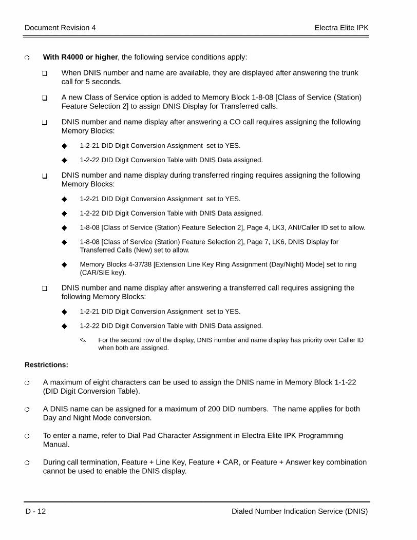
D - 12 Dialed Number Indication Service (DNIS)
___________________________________________________________________________________
___________________________________________________________________________________Document Revision 4 Electra Elite IPK
With R4000 or higher, the following service conditions apply:
When DNIS number and name are available, they are displayed after answering the trunk call for 5 seconds.
A new Class of Service option is added to Memory Block 1-8-08 [Class of Service (Station) Feature Selection 2] to assign DNIS Display for Transferred calls.
DNIS number and name display after answering a CO call requires assigning the following Memory Blocks:
1-2-21 DID Digit Conversion Assignment set to YES.
1-2-22 DID Digit Conversion Table with DNIS Data assigned.
DNIS number and name display during transferred ringing requires assigning the following Memory Blocks:
1-2-21 DID Digit Conversion Assignment set to YES.
1-2-22 DID Digit Conversion Table with DNIS Data assigned.
1-8-08 [Class of Service (Station) Feature Selection 2], Page 4, LK3, ANI/Caller ID set to allow.
1-8-08 [Class of Service (Station) Feature Selection 2], Page 7, LK6, DNIS Display for Transferred Calls (New) set to allow.
Memory Blocks 4-37/38 [Extension Line Key Ring Assignment (Day/Night) Mode] set to ring (CAR/SIE key).
DNIS number and name display after answering a transferred call requires assigning the following Memory Blocks:
1-2-21 DID Digit Conversion Assignment set to YES.
1-2-22 DID Digit Conversion Table with DNIS Data assigned.
For the second row of the display, DNIS number and name display has priority over Caller ID when both are assigned.
Restrictions:
A maximum of eight characters can be used to assign the DNIS name in Memory Block 1-1-22 (DID Digit Conversion Table).
A DNIS name can be assigned for a maximum of 200 DID numbers. The name applies for both Day and Night Mode conversion.
To enter a name, refer to Dial Pad Character Assignment in Electra Elite IPK Programming Manual.
During call termination, Feature + Line Key, Feature + CAR, or Feature + Answer key combination cannot be used to enable the DNIS display.
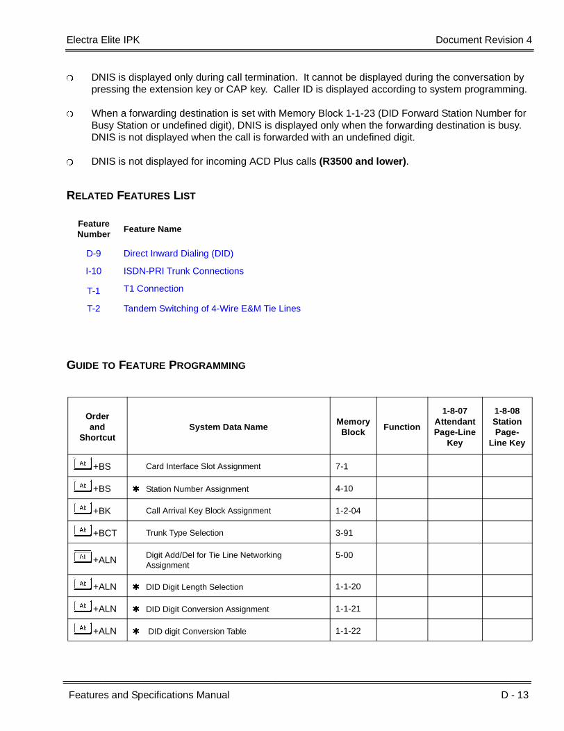
Electra Elite IPK Document Revision 4
Features and Specifications Manual D - 13
___________________________________________________________________________________
___________________________________________________________________________________
DNIS is displayed only during call termination. It cannot be displayed during the conversation by pressing the extension key or CAP key. Caller ID is displayed according to system programming.
When a forwarding destination is set with Memory Block 1-1-23 (DID Forward Station Number for Busy Station or undefined digit), DNIS is displayed only when the forwarding destination is busy. DNIS is not displayed when the call is forwarded with an undefined digit.
DNIS is not displayed for incoming ACD Plus calls (R3500 and lower).
RELATED FEATURES LIST
GUIDE TO FEATURE PROGRAMMING
Feature Number
Feature Name
D-9 Direct Inward Dialing (DID)
I-10 ISDN-PRI Trunk Connections
T-1 T1 Connection
T-2 Tandem Switching of 4-Wire E&M Tie Lines
Orderand
ShortcutSystem Data Name
MemoryBlock
Function
1-8-07AttendantPage-Line
Key
1-8-08StationPage-
Line Key
+BS Card Interface Slot Assignment 7-1
+BS Station Number Assignment 4-10
+BK Call Arrival Key Block Assignment 1-2-04
+BCT Trunk Type Selection 3-91
+ALN Digit Add/Del for Tie Line Networking Assignment
5-00
+ALN DID Digit Length Selection 1-1-20
+ALN DID Digit Conversion Assignment 1-1-21
+ALN DID digit Conversion Table 1-1-22

D - 14 Dialed Number Indication Service (DNIS)
___________________________________________________________________________________
___________________________________________________________________________________Document Revision 4 Electra Elite IPK
+ALNDID Forward Station Number for Busy station or Undefined Digit
1-1-23
+BTS Class of Service (Station) Feature Selection 2 1-8-08 4-3,4-4,5-7,7-6
+Al Caller ID Display Assignment for System Mode 1-1-78
+AI Caller ID Display for CAR Key Assignment 4-49
+BTT Station to Class of Service Feature Assignment 4-17
+BTT Telephone to Tenant Assignment 4-09
+BN Line Key Selection 2-05
+BN Line Key Selection for Tenant Mode 2-06
+BTM Line Key Selection for Telephone Mode 4-12
+BTT CO/PBX Ring Assignment (Day Mode) 4-01
+BTT CO/PBX Ring Assignment (Night Mode) 4-02
+BTMExtension Line Key Ring Assignment (Day Mode)
4-37
+BTMExtension Line Key Ring Assignment (Night Mode)
4-38
When the system is at default this Memory Block must be programmed for the feature to be used.
Orderand
ShortcutSystem Data Name
MemoryBlock
Function
1-8-07AttendantPage-Line
Key
1-8-08StationPage-
Line Key
Features and Specifications Manual D - 15
___________________________________________________________________________________
___________________________________________________________________________________
Dial 0 For Attendant D-5
FEATURE DESCRIPTION
Stations can access a system Attendant Position by dialing 0 (zero).
SYSTEM AVAILABILITY
Terminal Type:
All Stations
Required Components:
None
OPERATING PROCEDURES
Using a Multiline Terminal:
1. Lift the handset or press E , and wait for internal dial tone.
2. DialKto call the Attendant (set at default).
3. Lift the handset to talk with Attendant.
Using a Single Line Telephone:
1. Lift the handset, and wait for internal dial tone.
2. DialKto call the Attendant (set at default).
3. Talk with the Attendant.

D - 16 Dial 0 For Attendant
___________________________________________________________________________________
___________________________________________________________________________________Document Revision 4 Electra Elite IPK
SERVICE CONDITIONS
General:
Any station can be called by dialing 0 (default: All stations call station 100).
The Attendant can also be called by dialing the applicable station number.
When dialing a busy Attendant and receiving call waiting tone, the Step Call feature can be used to advance to an idle station.
Restrictions:
The system can have multiple Attendants. Only one can be called by dialing 0. When that Attendant dials 0, an error tone is received.
RELATED FEATURES LIST
GUIDE TO FEATURE PROGRAMMING
Feature Number
Feature Name
A-11 Attendant Add-On Console
A-13 Attendant Positions
Orderand
ShortcutSystem Data Name
Memory Block
Function
1-8-07AttendantPage-Line
Key
1-8-08StationPage-
Line Key
+BA Access Code (1-Digit) Assignment 1-1-46 176
+BA Specified Station Access Code Assignment 1-2-08

Features and Specifications Manual D - 17
___________________________________________________________________________________
___________________________________________________________________________________
Digit Insertion D-6
FEATURE DESCRIPTION
Digit Insertion provides user friendly operation when the system is installed behind a PBX or Centrex Central Office. When a system user originates an outgoing call, the system automatically inserts the PBX/Centrex Trunk Access Code. This feature saves the user from dialing an additional Access Code.
SYSTEM AVAILABILITY
Terminal Type:
All Stations
Required Components:
None
OPERATING PROCEDURES
To make a call using Digit Insertion:
1. Lift the handset, and wait for internal dial tone.
2. Dial the Trunk Access Code, then dial the desired telephone number.
SERVICE CONDITIONS
General:
The Trunk Access Code of the Electra Elite IPK should be the same number as the Trunk Access Code of the PBX/Centrex.
An outside call by Digit Insertion feature complies with Code Restriction.
Digit Insertion can be assigned per Trunk group.
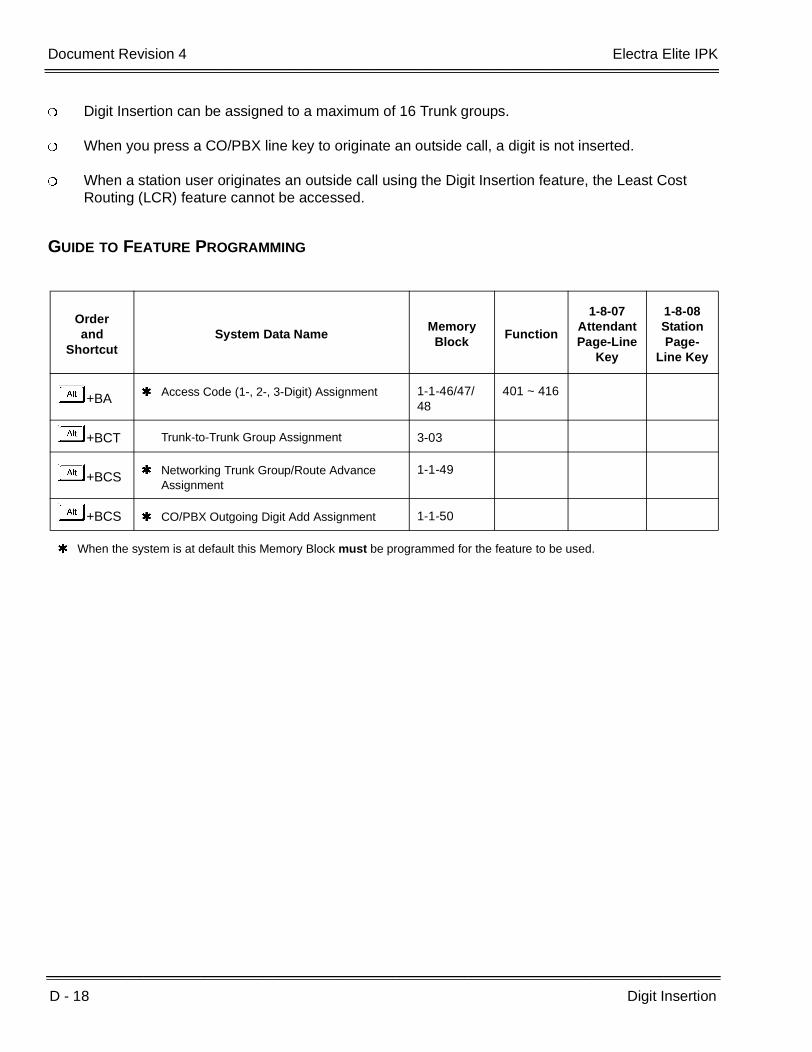
D - 18 Digit Insertion
___________________________________________________________________________________
___________________________________________________________________________________Document Revision 4 Electra Elite IPK
Digit Insertion can be assigned to a maximum of 16 Trunk groups.
When you press a CO/PBX line key to originate an outside call, a digit is not inserted.
When a station user originates an outside call using the Digit Insertion feature, the Least Cost Routing (LCR) feature cannot be accessed.
GUIDE TO FEATURE PROGRAMMING
Orderand
ShortcutSystem Data Name
Memory Block
Function
1-8-07AttendantPage-Line
Key
1-8-08StationPage-
Line Key
+BA Access Code (1-, 2-, 3-Digit) Assignment 1-1-46/47/48
401 ~ 416
+BCT Trunk-to-Trunk Group Assignment 3-03
+BCS Networking Trunk Group/Route Advance Assignment
1-1-49
+BCS CO/PBX Outgoing Digit Add Assignment 1-1-50
When the system is at default this Memory Block must be programmed for the feature to be used.
Features and Specifications Manual D - 19
___________________________________________________________________________________
___________________________________________________________________________________
Digital Line Extender (Dterm ®
ISDN EXTender Plus) D-7
FEATURE DESCRIPTION
Dterm ISDN EXTender Plus allows a user with an NEC Multiline Telephone to make/receive calls from a remote location while maintaining a station appearance from the office KTS and permits data access to the office LAN.
SYSTEM AVAILABILITY
Terminal Type:
DTP-32DE-1 (Dterm Series E)
Required Components:
Electra Elite KTS with 1 ESI port
ISDN BRI at office and remote site
Dterm ISDN EXTender Plus Office Module
Dterm ISDN EXTender Plus Remote Module
OPERATING PROCEDURES
Same as Multiline Terminal.
SERVICE CONDITIONS
General:
Refer to Dterm ISDN EXTender Plus System Administrator’s Guide for more information.
TAPI is not supported.

D - 20 Digital Line Extender (Dterm ® ISDN EXTender Plus)
___________________________________________________________________________________
___________________________________________________________________________________Document Revision 4 Electra Elite IPK
Restrictions:
The user must use a line that is not connected to the Dterm EXT Plus to make 911 calls. When a call is made from the remote terminal, the telephone number at the KTS location is sent to the emergency center.
Zone and voice paging must be turned off using KTS programming. The remote telephone should be programmed to ring for all incoming calls.
When the remote Multiline Terminal is programmed to answer multiple calls, these calls should ring at the terminal. Contact your authorized NEC dealer when system changes are required.
Synchronous ringing does not operate on the remote telephone. Incoming trunk calls automatically ring 2 sec. on/2 sec. off.
Analog fax machines and modems cannot operate with a DTP-32DE-1 Multiline Terminal that is connected to an APR-U Unit optional adapter.
Dterm Cordless terminals cannot be used with a DTP-32DE-1 Multiline Terminal or Dterm ISDN EXTender Plus.
CTA-U Unit and CTU(S)-U Unit cannot be installed to a KTS remote Multiline Terminal to provide TAPI functionality with the KTS.
The HFU-U/HF-R Unit handsfree adapter cannot operate with a DTP-32DE-1 Multiline Terminal or Dterm ISDN EXTender Plus used in a home environment because of FCC restrictions, but it can operate in an office environment.
Use Memory Block 4-01 [CO/PBX Ring Assignment (Day Mode)] or 4-02 [CO/PBX Ring Assignment (night Mode)] to assign incoming CO/PBX calls to ring on Multiline Terminals.
Use Memory Block 4-31 (Receiving Internal/All Call Page Selection) to disable paging for the station (set to NO).
When 5-, 6-, or 7-digit station numbers are used, this feature is not available.

Features and Specifications Manual D - 21
___________________________________________________________________________________
___________________________________________________________________________________
Digital Voice Mail D-8
FEATURE DESCRIPTION
The VMS(4)/(8)-U( ) ETU, FMS(2)/(4)/(8)-U( ) ETU, CMS(2)/(4)-U( ) ETU, VMP(2)/(4)/(8)-U(30/40 ) ETU or CTI/VP(4)/(8)/(12)/(16)-U( ) ETU provides Digital Voice Mail Service, Automated Attendant (AA), Audiotext, Fax Detection, Message Notification, Live Record, and Centrex Transfer. The VMS, FMS, CMS and VMP ETUs are complete voice mail applications (EliteMail) built on a single ETU. This method has advantages that include tighter application integration and built-in battery backup for the complete system. The CTI/VP(12)/(16)-U( ) ETU is built on two ETUs.
Descriptions are provided below.
Voice Mail Service
Voice Mail allows a caller to leave a recorded message in their voice and exact words for another individual.
Automated Attendant
The Automated Attendant answers a call, determines the extension, and transfers the call to that extension.
Audiotext
Audiotext provides around the clock information and allows an organization to present it with natural voice, music, or whatever they want callers to hear.
Fax Detect Routing and Notification
Incoming faxes are detected and automatically delivered to a fax machine. When using the fax machine handset, the fax originator can record a voice message that can be sent to the attendant.
Live Record
Live Record simplifies Message and note taking by permitting all or a portion of the conversation in progress to be recorded.
Centrex Transfer by Digital Voice Mail Port
A Digital Voice Mail Centrex Transfer feature allows the SLT Hookflash dial access code to be accessed by a Digital Voice Mail (DVM) port to send a Hookflash to the outside network.

D - 22 Digital Voice Mail
___________________________________________________________________________________
___________________________________________________________________________________Document Revision 4 Electra Elite IPK
ENHANCEMENTS
VMP( )-U30/U40 ETU Q51531(VMS)
Orderly Shutdown using the Shut Down Switch
The Shut Down Switch provides orderly shutdown of the voicemail Application and turns off theETU when placed in OFF. When no calls are active on voicemail, this procedure takes about 30seconds. The voicemail application waits until all active calls are finished before shutting down.
Subscriber-Based Multilingual
When an additional language license is added, the system manager can select a specific languagefor a specific subscriber at the console. The subscriber hears that language after login iscompleted. The default language is the system default language.
Entity-Based Multilingual
When an additional language license is added, this feature allows an outside caller to select a valid system language to use during the call. This feature allows any caller to hear any installed language regardless of which voicemail port answered the call. A new database entity, the Language Selection Box, is added to allow callers to choose between the installed languages. Each database entity (e.g., personal message box, transaction box, or interview box) can have a language associated with it.
Q50131
The following features are added in EliteMail Q50131 software and are only available in U.S English.
Timestamp Before Message
This option allows a subscriber to hear the message timestamp before the message is played back.
Multiple Entity Addressing
This option allows a subscriber to send or redirect a message to a number of subscribers, groups, or guests simultaneously. This feature is enabled at default and is accessed by dialing 77 when sending messages from a subscriber mailbox.
Password Security – Require Password
This option allows the system Administrator to require passwords. When this setting is enabled, subscribers cannot opt out of setting a password during first-time enrollment or when changing a password.
Password Security – Default Password
This option allows the system Administrator to change the default password for new subscriber mailboxes.

Electra Elite IPK Document Revision 4
Features and Specifications Manual D - 23
___________________________________________________________________________________
___________________________________________________________________________________
Control Access to Notification field
This option adds a subscriber setting called Allow Notification Access. This field controls whether or not a subscriber transfer option, the extension destination for auto attendant transferred calls, and pager notification numbers are accessible by the user in mailbox setup. When access is denied, these changes can be made only by the technician using console programming or from an internal station using softkeys.
SYSTEM AVAILABILITY
Terminal Type:
All stations (available for all features except Live Record).
Multiline Terminals (available for all features).
Required Components:
CMS(2)/(4)-U( ) ETU
FMS(2)/(4)/(8)-U( ) ETU
VMS(2)/(4)/(8)-U( ) ETU
VMP(2)/(4)/(8)-U(30/40) ETU
CTI/VP(4)/(8)/(12)/(16)-U( ) ETU
OPERATING PROCEDURES
To program the Feature Access key for Live Record at a Multiline Terminal:
1. Press A .
2. Press B .
3. Press the Feature Access key.
4. Dial B.
5. Dial the Live Record feature code.
Feature codes are:
KK = Record
KA = Pause
KB = Rerecord
KC = Erase
KD = End
KE = Urgent Page

D - 24 Digital Voice Mail
___________________________________________________________________________________
___________________________________________________________________________________Document Revision 4 Electra Elite IPK
KF = Address
KG = Live Monitor
6. Press A .
To program a One-Touch key for Live Record at a Multiline Terminal:
1. Press A .
2. Press B .
3. Press One-Touch key.
4. Dial B.
5. Dial the Live Record feature code.
Feature codes are:
KK = Record
KA = Pause
KB = Rerecord
KC = Erase
KD = End
KE = Urgent Page
KF = Address
KG = Live Monitor
6. Press A .
To set up personal mailboxes:
1. Lift handset and receive an internal dial tone.
2. Follow the verbal instructions to personalize the mailbox.

Electra Elite IPK Document Revision 4
Features and Specifications Manual D - 25
___________________________________________________________________________________
___________________________________________________________________________________
Digital Voice Mail Messages
To retrieve message at a Multiline Terminal or a Single Line Telephone:
1. Go off-hook; receive internal dial tone.
2. Dial the assigned station number to access Voice Mail.
3. Follow the verbal instructions provided by the Digital Voice Mail system or use the Softkeys on the telephone.
4. Follow the verbal instructions or use the Softkeys to navigate the system.
To program a One-Touch key for easy message access:
1. Press A .
2. Press B .
3. Press One-Touch key.
4. Dial A, followed by Voice Mail extension number.
5. Press A .
Live Record
To record an incoming CO/PBX conversation using Automatic Live Record:
1. Go off-hook to answer an incoming call. Live Record automatically starts. RECORD is displayed in the lower section of the LCD on a Multiline Terminal.
2. To store the recorded conversation in a different mailbox, dial a mailbox number or press a One-Touch key or Feature Access key programmed with the mailbox number. RECORD XXXXXX is displayed in the lower section of the LCD on a Multiline Terminal. (XXXXXX is the station name/number where the conversation is stored.)

D - 26 Digital Voice Mail
___________________________________________________________________________________
___________________________________________________________________________________Document Revision 4 Electra Elite IPK
To record a CO conversation in progress using Manual Live Record:
1. Press the Feature Access key programmed as the Record key. The Record key flashes red when Live Record begins and flashes green when Live Record is addressed. RECORD is displayed in the lower section of the LCD on a Multiline Terminal.
2. To store the recorded conversation, dial a mailbox number or press a One-Touch key or Feature Access key programmed with the mailbox number. RECORD XXXXXX is displayed in the lower section of the LCD on a Multiline Terminal. (XXXXXX is the station name/number where the conversation is stored.)
SERVICE CONDITIONS
Digital Voice Mail
General:
When a call is transferred to a station that is call forwarded to Voice Mail, or the Quick transfer to Voice Mail feature is used, the call must be released (blind transferred) before Voice Mail answers the call. During the transfer, the transferring party hears ring back tone, and the external party hears Music on Hold (MOH) or ringback tone until the transfer is completed. MOH or ring back tone is determined by Memory Block 4-66 (MOH or Ring Back Tone Selection). This condition applies to the following software versions:
An Electra Elite IPK system supports up to 32 DVM ports.
A VMP(X)-U(30/40) ETU, VMS(4)/(8)-U( ) ETU, FMS(2)/(4)/(8)-U( ) ETU, CMS(2)/(4)-U( ) ETU or CTI/VP(4)/(8)/(12)/(16)-U( ) ETU must be installed to provide Digital Voice Mail.
All Multiline Terminals (with or without an LCD) and Single Line Telephones (with a Message Wait Lamp) receive an indication that a Voice Mail message is waiting.
Multiline Terminals equipped with an LCD receive a message in the LCD indicating a message is waiting.
The Large LED and Feature (FNC) LED flashes red to indicate message waiting on all Multiline Terminals.
Single Line Telephones supported by an SLI(8)-U( ) ETU have the Message Wait LED On to indicate a message is waiting.
A Feature Access key or One-Touch key can be assigned for easy message access.
R1700 R2000 R2500 R3000 3500
R1.71 R2.01 R2.50 R3.00 R3.50
R2.02 R2.51 R3.01 R3.51

Electra Elite IPK Document Revision 4
Features and Specifications Manual D - 27
___________________________________________________________________________________
___________________________________________________________________________________
When a call transferred from a Voice Mail port is not answered in three minutes (fixed time), the call recalls to the Voice Mail port.
When a station is programmed for multiple Call Forward (e.g.,100 CFWD - 101 CFWD - VM Hunt Group) and a call is made to station 100, the caller is forwarded to the mailbox for station 100.
Voice Mail Message Waiting can be set/canceled only from a Voice Mail port.
The Digital Voice Mail recognizes the CO/PBX busy tone.
Refer to S-16 Station Hunt for specific information about station hunt groups.
The following major features are provided:
Voice Mail Service
Automated Attendant
Audiotext
Fax Detect, Routing and Notification
Optional Multilingual Prompts
The VMS( )-U30 ETU offers a standard built-in modem. Any port of the VMS( )-U30 ETU can be used to access the built-in modem by dialing an assigned extension number from the main greeting. The built-in modem is V.34 compatible and supports all standard speeds up to 28,800 bps
The VMP( )-U(30/40) ETU offers a standard built-in modem. Any port of the VMP( )-U(30/40) ETU can be used to access the built-in modem by dialing an assigned extension number from the main greeting. The built-in modem is V.34 compatible and supports all standard speeds up to 28,800 bps.
Restrictions:
When calling digital VM, the Pilot number assigned in Memory Block 1-8-26 (Voice Mail Quick Transfer Master Hunt Number) must be used.
Live Monitoring is not supported on CMS(2)/(4)-U( ) or VP(4)/(8)/(12)/(16)-U( ) ETU.
Live Record is not supported on CMS(2)/(4)-U( ) ETU.
Live Monitoring is supported on CTI(4)/(8)/(12)/(16)-U( ) ETU only when using ViewCall Plus.
When 5-, 6-, or 7-digit station numbers are used, this feature is not available.
When Voice Mail Message Waiting status is required to be sent across the K-CCIS link to a remote system, the Closed Number Blocks must be used.

D - 28 Digital Voice Mail
___________________________________________________________________________________
___________________________________________________________________________________Document Revision 4 Electra Elite IPK
Live Record
CAUTION
Using the Live Record feature to eavesdrop or record sound activities at the other end of the telephoneline may be illegal under certain circumstances and laws. Consult a legal advisor before implementingany practice to monitor or record a telephone conversation. Some federal and state laws require a partymonitoring or recording a telephone conversation to use a beep-tone(s), notify all parties to thetelephone conversation, and/or obtain consent of all parties to the telephone conversation. To monitor orrecord sound activities at the other end of the telephone line using the Live Record feature, the sound ofthe alert tone at the beginning of Live Record may or may not be considered sufficient under applicablelaws. Some applicable laws provide for strict penalties for illegal monitoring or recording of telephoneconversations.
General:
Tone Override, Call Alert, Barge-In, Camp-On, and Voice Over Split feature tones are denied during Live Record.
When a Multiline Terminal user completes Live Record without specifying a mailbox where the conversation should be stored and Automatic Recall is not assigned in Digital Voice Mail programming, the conversation is stored in the mailbox assigned to the Multiline Terminal. When a Multiline Terminal user completes Live Record without specifying a mailbox where the conversation should be stored and Automatic Recall is assigned in Digital Voice Mail programming, the conversation is stored in the mailbox assigned to the Multiline Terminal and the system recalls the Multiline Terminal and plays the recorded conversation.
(Auto Callback rings - 4 times, Waiting Time - 3 minute, Redial - 5 times.)
Live Record can be used only from Multiline Terminals.
Individual trunks must be assigned for the Live Record feature to operate.
The system can be programmed to allow/deny an alert tone for Live Record. The 0.5 second alert tone is heard by both the outside party and the Multiline Terminal user when the recording starts or at specified intervals during recording. The interval between alert tones is assigned in the Digital Voice Mail System Programming.
Up to seven feature keys can be programmed for use with Live Record. These feature keys can be assigned to Feature Access keys, One-Touch keys, or DSS keys (on a DSS/BLF console). When the feature keys are assigned to One-Touch keys, no LED indications are provided.
The following feature keys can be programmed:
Record Key
Use this key to manually start Live Record. The associated LED flashes red while recording. Theassociated LED goes off when recording ends or a pause occurs and flashes green when a liverecord message is addressed.

Electra Elite IPK Document Revision 4
Features and Specifications Manual D - 29
___________________________________________________________________________________
___________________________________________________________________________________
Pause Key
Use this key to pause and restart live record. The associated LED flashes green when recordinghas paused.
Erase Key
Use this key to erase the Live Record conversations. After the Erase key is pressed, the Voice Mailport remains off-hook until the call is terminated.
End Key
Use this key to end the Live Record. The conversation continues without being recorded.
Rerecord Key
Use this key to erase a recorded conversation while recording is in progress and start a newrecording.
Urgent Page Key
Use this key to change the Live Record assignment from dial out to pager. (Message Notificationto Pager Assignment cycles ON/OFF when this key is pressed while recording.)
Address Key
Use this key to confirm Live Record, erase Live Record, change the mailbox number where LiveRecord is stored, or add a recorded prelude to a recorded conversation.
During each Live Record, a conference circuit and Voice Mail Port are used.
Live Record is not allowed when all Add-On Conference circuits are busy.
Additional internal parties cannot be added to a live record conversation during conferencing.
Only CO/PBX, Tie, and DID calls can be recorded using Live Record. Internal calls cannot be recorded using Live Record.
The Record key LED is on when all conference circuits or all Digital Voice Mail ports are busy.
Any station user can direct a live record message to another station user.
Any Multiline Terminal can change the Message Notification mode to Pager Notification mode by first directing a live record message to another station and then pressing the Urgent Page key. The station that is put into the Urgent Page mode must have a pager telephone number assigned.
When a Multiline Terminal (with LCD) is in Pager Notification mode, is displayed in the far right corner of the lower LCD.
Live Record is not allowed on conference calls.

D - 30 Digital Voice Mail
___________________________________________________________________________________
___________________________________________________________________________________Document Revision 4 Electra Elite IPK
Centrex Transfer by Digital Voice Mail Port
General:
Centrex Transfer is supported for Release Transfer and Await Answer transfer modes.
All existing Voice Mail systems can support this transfer.
No new Memory Blocks are required.
The access code for SLT Hookflash (default 6#) must be assigned in system programming for this feature to operate.
Restrictions:
The CO used for Centrex transfer must be assigned as PBX in Memory Block 3-91 (Trunk Type Selection).
When 5-, 6-, or 7-digit station numbers are used, this feature is not available.
CoSession
Description
CoSession, a communication software tool available from NEC, is used for EliteMail to perform configuration, maintenance, and backup functions.
CoSession Client 7.0 is supported with the following operating systems:
Windows 9x
Windows NT 4.0
Windows 2000/2000 Pro
Windows XP Home/Professional
Computer
The computer used as the CoSession client must be an x86-based PC desktop or notebook system meeting the minimum requirements for the chosen operating system.
Modem/Serial cable
An AT-command set modem is required for remote connections via modem. A null-modem cable is required for use in a direct-connection.
When using CoSession on Windows NT 4.0, Windows 2000, or Windows XP, COM ports can be initialized for use at up to 57,600 bps. Using those operating systems, COM ports cannot be initialized for use at 115,200 bps.
CoSession file transfer operations perform reliably up to 38,400 bps.

Electra Elite IPK Document Revision 4
Features and Specifications Manual D - 31
___________________________________________________________________________________
___________________________________________________________________________________
Digital Voice Mail Features
Feature
EliteMailCMS
EliteMailFMS
EliteMailVMS
EliteMailVMP
EliteMailVP
EliteMailCTI
Live Record No Yes Yes Yes Yes Yes
Live Monitor No YesQ05631or higher
YesQ00631or higher
Yes No YesNote 5
Caller ID Display No YesQ05631or higher
YesQ00631or higher
Yes No YesNote 1Note 3
Caller ID Call Return
No YesQ05931or higher
YesQ00931or higher
Yes No YesNote 2Note 4
Softkeys No Yes Yes Yes Yes Yes
TeLANophy (View Mail, VMM, View Call Plus, View Fax)
No No No No No Yes
Multiple Languages No No Yes Yes, Note 6 Yes Yes
Hotel/MotelFeatures
No No No No No Yes
Centrex Transfer Yes Yes Yes Yes Yes Yes
Pager Notification Yes Yes Yes Yes Yes Yes
Auto Attendant Yes Yes Yes Yes Yes Yes
Fax Detect andRouting
Yes Yes Yes Yes Yes Yes
Timestamp Before Message
NO YesQ50131 or
higher
YesQ50131 or
higher
Yes NO NO
Multiple Entity Addressing
NO YesQ50131 or
higher
YesQ50131 or
higher
Yes NO NO
Password Security – Require Password
NO YesQ50131or
higher
YesQ50131or
higher
Yes NO NO
Password Security –Default Password
NO YesQ50131 or
higher
YesQ50131or
higher
Yes NO NO
Control Access to Notification Field
NO YesQ50131 or
higher
YesQ50131 or
higher
Yes NO NO
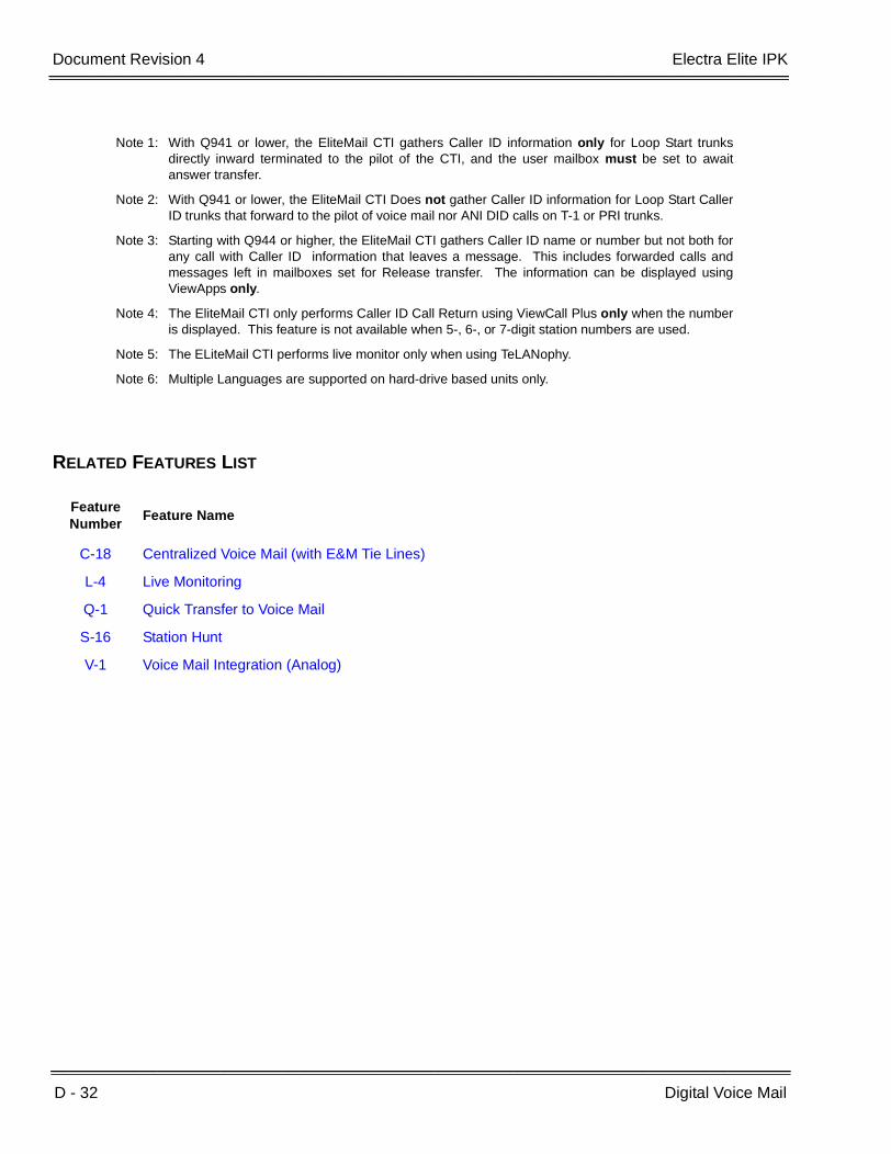
D - 32 Digital Voice Mail
___________________________________________________________________________________
___________________________________________________________________________________Document Revision 4 Electra Elite IPK
RELATED FEATURES LIST
Note 1: With Q941 or lower, the EliteMail CTI gathers Caller ID information only for Loop Start trunksdirectly inward terminated to the pilot of the CTI, and the user mailbox must be set to awaitanswer transfer.
Note 2: With Q941 or lower, the EliteMail CTI Does not gather Caller ID information for Loop Start CallerID trunks that forward to the pilot of voice mail nor ANI DID calls on T-1 or PRI trunks.
Note 3: Starting with Q944 or higher, the EliteMail CTI gathers Caller ID name or number but not both forany call with Caller ID information that leaves a message. This includes forwarded calls andmessages left in mailboxes set for Release transfer. The information can be displayed usingViewApps only.
Note 4: The EliteMail CTI only performs Caller ID Call Return using ViewCall Plus only when the numberis displayed. This feature is not available when 5-, 6-, or 7-digit station numbers are used.
Note 5: The ELiteMail CTI performs live monitor only when using TeLANophy.
Note 6: Multiple Languages are supported on hard-drive based units only.
Feature Number
Feature Name
C-18 Centralized Voice Mail (with E&M Tie Lines)
L-4 Live Monitoring
Q-1 Quick Transfer to Voice Mail
S-16 Station Hunt
V-1 Voice Mail Integration (Analog)

Electra Elite IPK Document Revision 4
Features and Specifications Manual D - 33
___________________________________________________________________________________
___________________________________________________________________________________
GUIDE TO FEATURE PROGRAMMING
Digital Voice Mail (Installation)
Orderand
ShortcutSystem Data Name
Memory Block
Function
1-8-07AttendantPage-Line
Key
1-8-08StationPage-
Line Key
+BS Card Interface Slot Assignment 7-1
+BS Telephone Type Assignment 7-2
+BS Station Number Assignment 4-10
+BTT Intercom Master Hunt Number Selection 4-14
+BTT Intercom Master Hunt Number Forward Selection
4-15
+AV Voice Mail Quick Transfer Master Hunt Number
1-8-26
+BA Intercom Feature Access Code Assignment 1-2-24 007
+BTSClass of Service (Station) Feature Selection 2 1-8-08 1-1, 2-5,
4-5, 4-6
+BTTStation to Class of Service Feature Assignment
4-17
+BA
Access Code (1-, 2-, 3-Digit) Assignment 1-1-46/47/48
020 ~ 025,030, 032,033, 034,140~143,027
+BCM Hookflash Time Selection 1-1-02
+BCT DIT Assignment 3-42
+BCT ANA Assignment 3-43
+AV Live Record Trunk Selection 3-45
+AV Live Record Auto Delete Selection 4-46
+BTM Line Key Selection for Telephone Mode 4-12
+BTD Attendant Add-On Console Key Selection 1-6-05
When the system is at default this Memory Block must be programmed for the feature to be used.
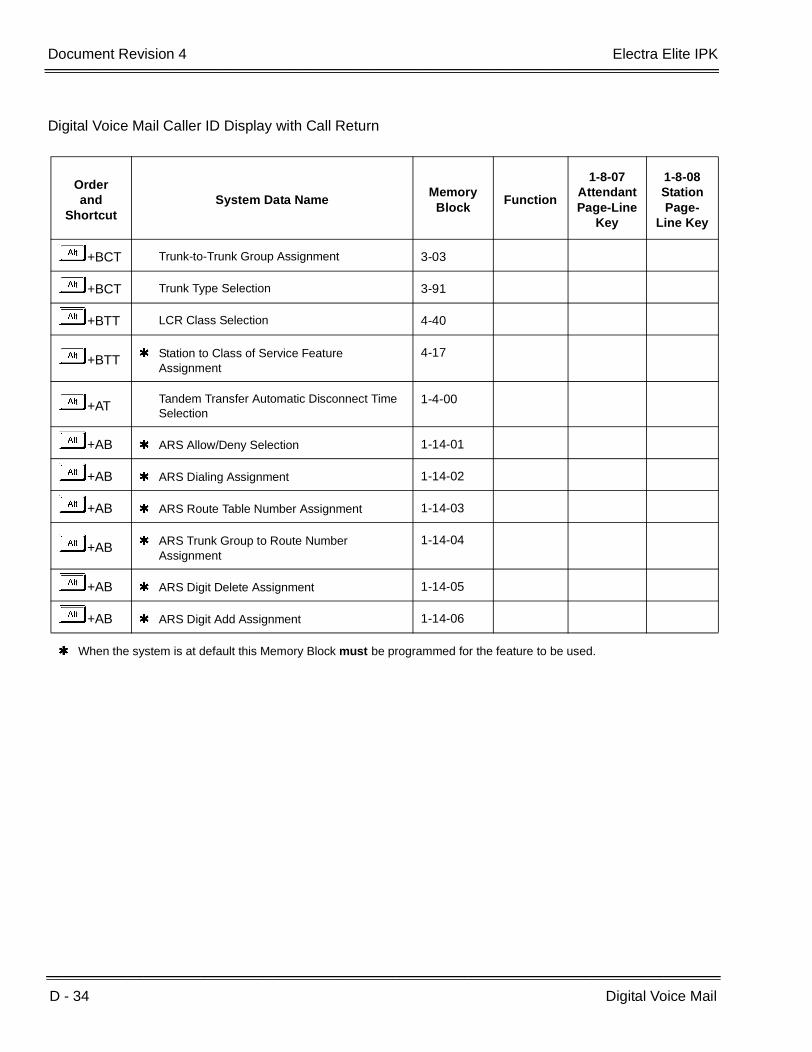
D - 34 Digital Voice Mail
___________________________________________________________________________________
___________________________________________________________________________________Document Revision 4 Electra Elite IPK
Digital Voice Mail Caller ID Display with Call Return
Orderand
ShortcutSystem Data Name
Memory Block
Function
1-8-07AttendantPage-Line
Key
1-8-08StationPage-
Line Key
+BCT Trunk-to-Trunk Group Assignment 3-03
+BCT Trunk Type Selection 3-91
+BTT LCR Class Selection 4-40
+BTT Station to Class of Service Feature Assignment
4-17
+ATTandem Transfer Automatic Disconnect Time Selection
1-4-00
+AB ARS Allow/Deny Selection 1-14-01
+AB ARS Dialing Assignment 1-14-02
+AB ARS Route Table Number Assignment 1-14-03
+AB ARS Trunk Group to Route Number Assignment
1-14-04
+AB ARS Digit Delete Assignment 1-14-05
+AB ARS Digit Add Assignment 1-14-06
When the system is at default this Memory Block must be programmed for the feature to be used.

Features and Specifications Manual D - 35
___________________________________________________________________________________
___________________________________________________________________________________
Direct Inward Dialing (DID) D-9
FEATURE DESCRIPTION
Direct Inward Dialing (DID) lines can be connected to the system. With DID, incoming calls from the CO can reach any station in the system without Attendant intervention.
ENHANCEMENT(S)
With R4000 or higher, the BRT(4)-U( ) ETU using 3.00 or higher firmware can support DID for ISDN-BRI trunks.
SYSTEM AVAILABILITY
Terminal Type:
All Multiline Terminals
Required Components:
DID(4)-U( ) ETU, PRT(1)-U( ) ETU, DTI-U( ) ETU, or PRT(1)-U( ) ETU with firmware 2.00 or higher
BRT(4)-U20 with Firmware 3.00 or higher.
OPERATING PROCEDURES
None
SERVICE CONDITIONS
General:
When the number of DID incoming calls is not over the limit, and DID Forward Station Number for Busy Station or Undefined Digit is active, forwarding is activated.

D - 36 Direct Inward Dialing (DID)
___________________________________________________________________________________
___________________________________________________________________________________Document Revision 4 Electra Elite IPK
A total of 16 DID(4)-U( ) ETUs can be installed in the Expanded Port Package system. A total of four DID(4)-U( ) ETUs can be installed in the Electra Elite IPK Basic Port Package. Each DID(4)-U( ) ETU provides connection circuitry to handle up to four DID lines. The Electra Elite IPK Expanded Port Package is limited to 64 trunks and the Basic Port Package is limited to 16 trunks.
Each port of the DID(4)-U( ) ETU can be set to receive DTMF or DP (10 pps or 20 pps) signaling.
Incoming calls on DID lines follow Call Forward and Station Hunting.
DID calls can be routed to an ACD or UCD Hunt group.
Incoming DID calls can be assigned for voice announcement from the outside party, system-wide.
Outgoing restriction can be assigned, per station, to DID lines to prevent access when the line is assigned on a line key.
DIDs can be routed to specified tenants using Memory Block 1-1-22 (DID Digit Conversion Table).
When a call is terminated to a tenant, termination indication and ringing is performed only on telephones in that tenant. On the telephones in other tenants, the red CO line key LED is on and ringing is not assigned.
Termination to a tenant can also be specified as the destination for the Busy Station or undefined digits.
DID incoming call termination can also be performed to the destination in the DID conversion table (Day or Night) according to the day and night modes for that specified Tenant.
When the number of DID incoming calls is over, a busy signal is sent to the network. User Busy is displayed when an incoming ISDN call is refused. The reason is Cause #17.
The following DID calls are counted against the number of total calls:
A call that is placed on hold, transferred, or conferenced.
A call received by one Tenant and Transferred to another Tenant counts against the first Tenant.
A call that is received and disconnected.
Incoming DID numbers can be routed to any station in the system regardless of the numbering plan. When an incoming DID number is invalid, the call can be sent to a preassigned station or hunt group pilot number.
Use Memory Block 5-00 (Digit Add/Del for Tie Line Networking Assignment) to add and/or delete a maximum of two digits per trunk group, from the incoming DID digits provided by the DID trunk for incoming address signaling. Setting 0 allows DID Full Digit Modification that collects the incoming digits and sends the call to a specified station number.

Electra Elite IPK Document Revision 4
Features and Specifications Manual D - 37
___________________________________________________________________________________
___________________________________________________________________________________
When a DID incoming call is not answered before a time specified in Memory Block 1-1-07 (Tie Line Delay Ringing Time Selection) (default: ∞, no timeout), the call can switch to normal Day or Night ringing assignment.
Use Memory Block 1-1-55 (DID Line Ringing Pattern Selection) to change the ringing pattern (default: A) for an incoming DID call.
Use Memory Block 2-09 (DID Limit to Tenant Assignment) to specify the number of calls allowed to ring at a specified Tenant.
Restrictions:
Memory Block 1-4-02 (Automated Attendant Transfer Delayed Ringing Time Selection) is not required to time out before incoming DID calls can be answered by the Automated Attendant (can be set to No Limit).
A DID call does not activate External Tone Ringer or Night Chime.
When an incoming DID call changes to normal ringing, the call is still counted toward the number of effective calls to the Tenant.
When the number of DID incoming calls is over the limit, and DID Forward Station Number for Busy Station or Undefined Digit is active, forwarding is not activated, and the outside party receives a Burst Tone.
When 5-, 6-, or 7-digit station numbers are used, DID Digit Conversion is not supported.
GUIDE TO FEATURE PROGRAMMING
Orderand
ShortcutSystem Data Name
Memory Block
Function
1-8-07AttendantPage-Line
Key
1-8-08StationPage-
Line Key
+BS Card Interface Slot Assignment 7-1
+BCT Trunk-to-Trunk Group Assignment 3-03
+BCT Trunk Type Selection 3-91
+ALT Tie Line Type Assignment 3-14
+ALN Tie Line First Ring Pattern Selection 1-1-34
+ALN Tie Line Delay Ring Pattern Selection 1-1-53
+ALN DID Line Ringing Pattern Selection 1-1-55
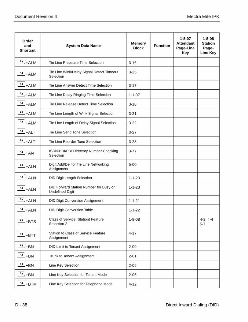
D - 38 Direct Inward Dialing (DID)
___________________________________________________________________________________
___________________________________________________________________________________Document Revision 4 Electra Elite IPK
+ALM Tie Line Prepause Time Selection 3-16
+ALMTie Line Wink/Delay Signal Detect Timeout Selection
3-25
+ALM Tie Line Answer Detect Time Selection 3-17
+ALM Tie Line Delay Ringing Time Selection 1-1-07
+ALM Tie Line Release Detect Time Selection 3-18
+ALM Tie Line Length of Wink Signal Selection 3-21
+ALM Tie Line Length of Delay Signal Selection 3-22
+ALT Tie Line Send Tone Selection 3-27
+ALT Tie Line Reorder Tone Selection 3-28
+ANISDN-BRI/PRI Directory Number Checking Selection
3-77
+ALNDigit Add/Del for Tie Line Networking Assignment
5-00
+ALN DID Digit Length Selection 1-1-20
+ALNDID Forward Station Number for Busy or Undefined Digit
1-1-23
+ALN DID Digit Conversion Assignment 1-1-21
+ALN DID Digit Conversion Table 1-1-22
+BTSClass of Service (Station) Feature Selection 2
1-8-08 4-3, 4-45-7
+BTTStation to Class of Service Feature Assignment
4-17
+BN DID Limit to Tenant Assignment 2-09
+BN Trunk to Tenant Assignment 2-01
+BN Line Key Selection 2-05
+BN Line Key Selection for Tenant Mode 2-06
+BTM Line Key Selection for Telephone Mode 4-12
Orderand
ShortcutSystem Data Name
Memory Block
Function
1-8-07AttendantPage-Line
Key
1-8-08StationPage-
Line Key

Electra Elite IPK Document Revision 4
Features and Specifications Manual D - 39
___________________________________________________________________________________
___________________________________________________________________________________
+BTT Telephone to Tenant Assignment 4-09
+BTT CO/PBX Ring Assignment (Day Mode) 4-01
+BTT CO/PBX Ring Assignment (Night Mode) 4-02
+BTMExtension Line Key Ring Assignment (Day Mode)
4-37
+BTMExtension Line Key Ring Assignment (Night Mode)
4-38
When the system is at default this Memory Block must be programmed for the feature to be used.
Orderand
ShortcutSystem Data Name
Memory Block
Function
1-8-07AttendantPage-Line
Key
1-8-08StationPage-
Line Key

D - 40 Direct Inward Dialing (DID)
___________________________________________________________________________________
___________________________________________________________________________________Document Revision 4 Electra Elite IPK
THIS PAGE INTENTIONALLY LEFT BLANK

Features and Specifications Manual D - 41
___________________________________________________________________________________
___________________________________________________________________________________
Direct Inward System Access (DISA) D-10
FEATURE DESCRIPTION
Direct Inward System Access (DISA) allows an outside caller to access the system from an outside line without Attendant or station assistance. The outside user may originate a call over any system facility such as a Tie line network or CO/PBX trunk after successfully entering a password.
SYSTEM AVAILABILITY
Terminal Type:
Not applicable
Required Components:
VRS(4)-U( ) ETU to hear a message telling the caller which digits to enter for DISA access. A message is not required for DISA to work.
OPERATING PROCEDURES
To place a call using DISA:
1. Dial the desired number to connect to the system.
2. A special tone is heard after ringback tone. When a VRS(4)-U( ) ETU is programmed for DISA, a voice announcement can be provided instead of a special tone.
3. Dial the DISA Access Code.
When accepted, internal dial tone is heard.
When denied, error tone is heard.
4. Dial the DISA ID code (Station Number).
5. Dial the password.
6. Dial a Trunk Access Code and the desired outside number.

D - 42 Direct Inward System Access (DISA)
___________________________________________________________________________________
___________________________________________________________________________________Document Revision 4 Electra Elite IPK
To place an internal call using DISA:
1. Dial the desired number to connect the system.
2. Dial the station number.
To change a DISA password:
1. Go off-hook.
2. Dial the DISA password set Access Code XX (default not assigned, System Programmable).
3. Enter the ID code (station number is default).
4. Enter the DISA password (default: KKKKKKKKKK).
5. Enter the new DISA password (maximum: 10 digits).
6. Go on-hook.
To reset the DISA password at the Attendant Position:
1. Go off-hook.
2. Dial the DISA password reset Access Code XX (default not assigned, System Programmable).
3. Enter the ID code (station number is default). Password is reset.
4. Go on-hook.
To confirm a DISA password at the Attendant Position:
1. Go off-hook.
2. Dial the DISA password confirmation Access Code XX (default not assigned, System Programmable).
3. Enter the ID code. Current password is displayed.
4. Go on-hook.
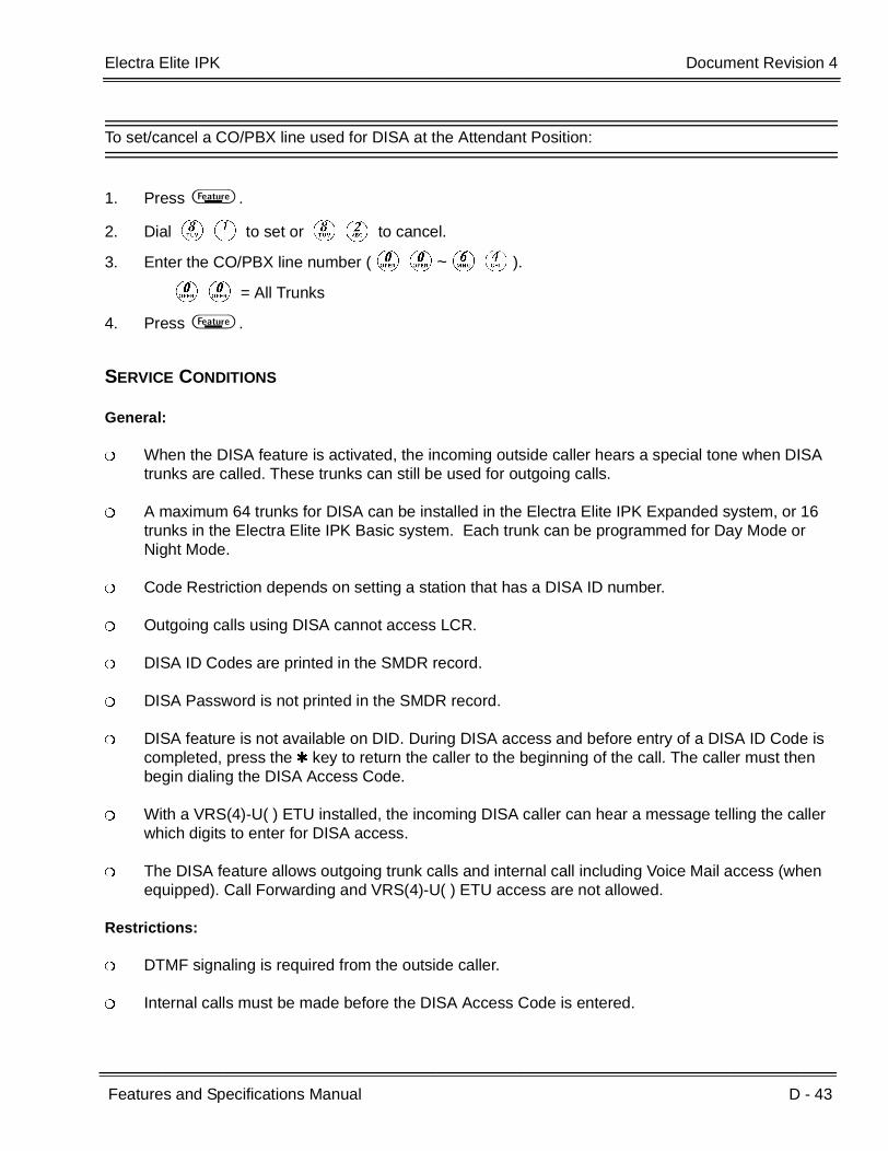
Electra Elite IPK Document Revision 4
Features and Specifications Manual D - 43
___________________________________________________________________________________
___________________________________________________________________________________
To set/cancel a CO/PBX line used for DISA at the Attendant Position:
1. Press A .
2. Dial HA to set or HB to cancel.
3. Enter the CO/PBX line number (KK~FD).
KK = All Trunks
4. Press A .
SERVICE CONDITIONS
General:
When the DISA feature is activated, the incoming outside caller hears a special tone when DISA trunks are called. These trunks can still be used for outgoing calls.
A maximum 64 trunks for DISA can be installed in the Electra Elite IPK Expanded system, or 16 trunks in the Electra Elite IPK Basic system. Each trunk can be programmed for Day Mode or Night Mode.
Code Restriction depends on setting a station that has a DISA ID number.
Outgoing calls using DISA cannot access LCR.
DISA ID Codes are printed in the SMDR record.
DISA Password is not printed in the SMDR record.
DISA feature is not available on DID. During DISA access and before entry of a DISA ID Code is completed, press the key to return the caller to the beginning of the call. The caller must then begin dialing the DISA Access Code.
With a VRS(4)-U( ) ETU installed, the incoming DISA caller can hear a message telling the caller which digits to enter for DISA access.
The DISA feature allows outgoing trunk calls and internal call including Voice Mail access (when equipped). Call Forwarding and VRS(4)-U( ) ETU access are not allowed.
Restrictions:
DTMF signaling is required from the outside caller.
Internal calls must be made before the DISA Access Code is entered.

D - 44 Direct Inward System Access (DISA)
___________________________________________________________________________________
___________________________________________________________________________________Document Revision 4 Electra Elite IPK
Only trunks assigned AA in Memory Block 3-05 (Trunk Incoming Answer Mode Selection) are set or canceled for Automated Attendant/DISA Mode when an Attendant enters 00 during the set or cancel operation.
When 5-, 6-, or 7-digit station numbers are used, the DISA ID Code is only four digits.
GUIDE TO FEATURE PROGRAMMING
Orderand
ShortcutSystem Data Name
Memory Block
Function
1-8-07AttendantPage-Line
Key
1-8-08StationPage-
Line Key
+BAAccess Codes (1-, 2-, 3-Digit) Assignment 1-1-46/47/
48251~ 253,
+AU Automated Attendant Message Day/Night Mode Selection
1-4-11
+BTI SLT or Automated Attendant/DISA to PBR Selection
1-8-01
+BCT Trunk Incoming Answer Mode Selection 3-05
+BTSClass of Service (Attendant) Feature Selection 1
1-8-07 1-8, 2-5,2-6
+BTS Class of Service (Station) Feature Selection 2 1-8-08 2-8
+BTTStation to Class of Service Feature Assignment
4-17
+BD DISA ID Code Assignment 1-9-00
+BD DISA Password Effect/Invalid Selection 1-9-02
+BD DISA ID Number Station Assignment 4-26
+AU Automated Attendant Message Access Code (1-Digit) Assignment
1-4-14
+AUAutomated Attendant Message Access Code (2-Digit) Assignment
1-4-15
+BTS Specified Station Access Code Assignment 1-2-08
+AUAutomated Attendant PBR Start Time Selection
1-4-09
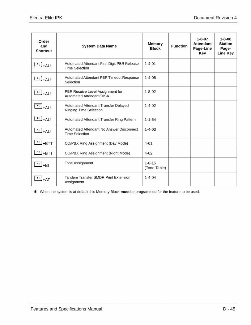
Electra Elite IPK Document Revision 4
Features and Specifications Manual D - 45
___________________________________________________________________________________
___________________________________________________________________________________
+AUAutomated Attendant First Digit PBR Release Time Selection
1-4-01
+AUAutomated Attendant PBR Timeout Response Selection
1-4-08
+AUPBR Receive Level Assignment for Automated Attendant/DISA
1-8-02
+AUAutomated Attendant Transfer Delayed Ringing Time Selection
1-4-02
+AU Automated Attendant Transfer Ring Pattern 1-1-54
+AUAutomated Attendant No Answer Disconnect Time Selection
1-4-03
+BTT CO/PBX Ring Assignment (Day Mode) 4-01
+BTT CO/PBX Ring Assignment (Night Mode) 4-02
+BITone Assignment 1-8-15
(Tone Table)
+ATTandem Transfer SMDR Print Extension Assignment
1-4-04
When the system is at default this Memory Block must be programmed for the feature to be used.
Orderand
ShortcutSystem Data Name
Memory Block
Function
1-8-07AttendantPage-Line
Key
1-8-08StationPage-
Line Key
D - 46 Direct Inward System Access (DISA)
___________________________________________________________________________________
___________________________________________________________________________________Document Revision 4 Electra Elite IPK
THIS PAGE INTENTIONALLY LEFT BLANK

Features and Specifications Manual D - 47
___________________________________________________________________________________
___________________________________________________________________________________
Direct Inward Termination (DIT) D-11
FEATURE DESCRIPTION
Direct Inward Termination (DIT) allows CO/PBX lines to be programmed to bypass the Attendant and ring directly at stations or tenants. A separate Assigned Night Answer (ANA) ringing assignment is available. A System or Tenant group can be set to the Night Mode independently.
System software supports delay ringing to DIT or to DIT trunks to a tenant.
SYSTEM AVAILABILITY
Terminal Type
All Stations
Required Components:
None
OPERATING PROCEDURES
No manual operation is required.
SERVICE CONDITIONS
General:
When an idle station programmed for DIT receives an incoming DIT call, internal ring tone is heard at the station(s) where a Secondary Incoming Extension is assigned to ring.
DIT incoming ringing is assigned for Distinctive Ring or Synchronous Ring system-wide.
When a busy station programmed for DIT receives an incoming DIT call, the system provides Camp-On tone for the busy station. The calling party receives ringback tone until the call is answered.
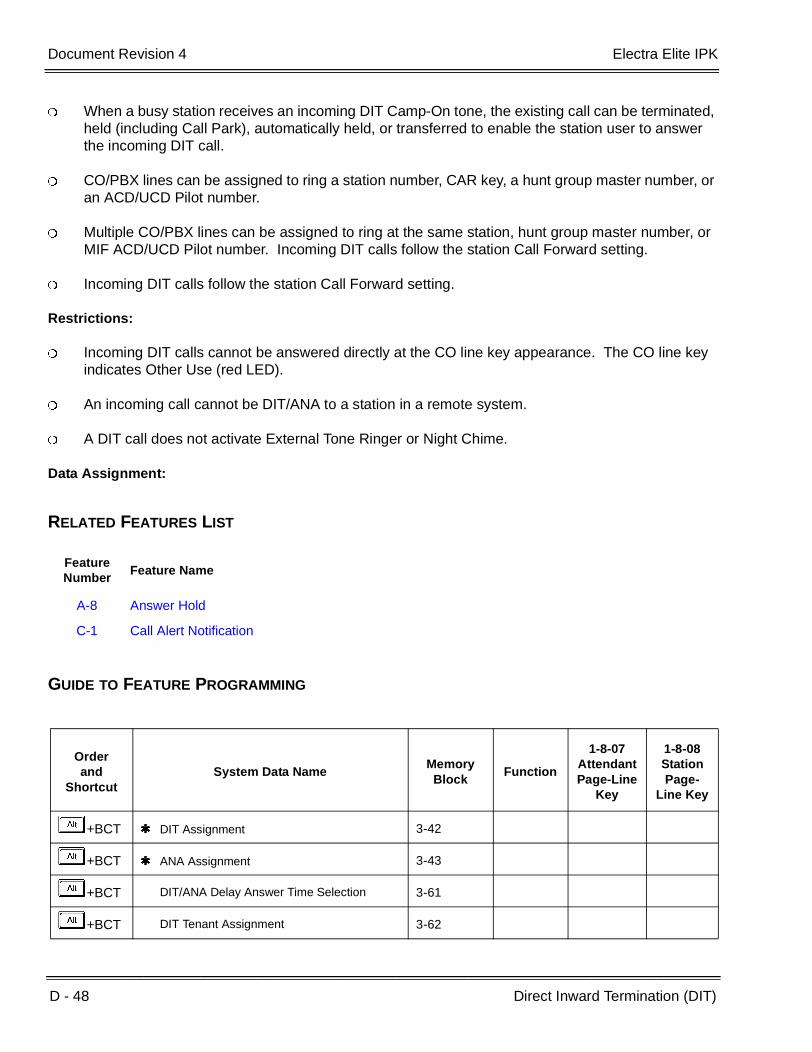
D - 48 Direct Inward Termination (DIT)
___________________________________________________________________________________
___________________________________________________________________________________Document Revision 4 Electra Elite IPK
When a busy station receives an incoming DIT Camp-On tone, the existing call can be terminated, held (including Call Park), automatically held, or transferred to enable the station user to answer the incoming DIT call.
CO/PBX lines can be assigned to ring a station number, CAR key, a hunt group master number, or an ACD/UCD Pilot number.
Multiple CO/PBX lines can be assigned to ring at the same station, hunt group master number, or MIF ACD/UCD Pilot number. Incoming DIT calls follow the station Call Forward setting.
Incoming DIT calls follow the station Call Forward setting.
Restrictions:
Incoming DIT calls cannot be answered directly at the CO line key appearance. The CO line key indicates Other Use (red LED).
An incoming call cannot be DIT/ANA to a station in a remote system.
A DIT call does not activate External Tone Ringer or Night Chime.
Data Assignment:
RELATED FEATURES LIST
GUIDE TO FEATURE PROGRAMMING
Feature Number
Feature Name
A-8 Answer Hold
C-1 Call Alert Notification
Orderand
ShortcutSystem Data Name
Memory Block
Function
1-8-07AttendantPage-Line
Key
1-8-08StationPage-
Line Key
+BCT DIT Assignment 3-42
+BCT ANA Assignment 3-43
+BCT DIT/ANA Delay Answer Time Selection 3-61
+BCT DIT Tenant Assignment 3-62

Electra Elite IPK Document Revision 4
Features and Specifications Manual D - 49
___________________________________________________________________________________
___________________________________________________________________________________
+BCT DIT Weekend Mode Selection 3-63
+BCT DIT Night Mode Delay Answer Selection 3-64
+BN Trunk to Tenant Assignment 2-01
+BN Line Key Selection for Tenant Mode 2-06
+BTT Telephone to Tenant Assignment 4-09
+BTM Line Key Selection for Telephone Mode 4-12
+BTTCall Forward - Busy Immediately/Delay Selection
4-42
+BM Call Forward - No Answer Time Selection 1-2-22
+AC Station to Timer Class of Service 4-71
When the system is at default this Memory Block must be programmed for the feature to be used.
Orderand
ShortcutSystem Data Name
Memory Block
Function
1-8-07AttendantPage-Line
Key
1-8-08StationPage-
Line Key

D - 50 Direct Inward Termination (DIT)
___________________________________________________________________________________
___________________________________________________________________________________Document Revision 4 Electra Elite IPK
THIS PAGE INTENTIONALLY LEFT BLANK

Features and Specifications Manual D - 51
___________________________________________________________________________________
___________________________________________________________________________________
Direct Paging Access D-12
FEATURE DESCRIPTION
The Attendant Add-On Console Direct Station Selection/Busy Lamp Field (DSS/BLF) keys allow direct access to Internal or External Page Zones or All Call Paging. Feature Access and One-Touch keys on the Multiline Terminals can be used for Direct Paging Access.
SYSTEM AVAILABILITY
Terminal Type:
All Multiline Terminals and Attendant Add-On Consoles
Required Components:
ECR-U( ) ETU for External Zone Paging
OPERATING PROCEDURES
To use this feature at a Multiline Terminal with a Feature Access or a One-Touch key programmed for Direct Paging Access or with the Attendant Add-On Console assigned:
1. Go off-hook.
2. Press the Direct Paging Access key.
3. Make the paging announcement.

D - 52 Direct Paging Access
___________________________________________________________________________________
___________________________________________________________________________________Document Revision 4 Electra Elite IPK
SERVICE CONDITIONS
General:
When a Direct Paging Access key for All Internal Zone or Internal Zone Page on the Attendant Add-On Console is pressed, a paging announcement is made over the speakers of all idle Multiline Terminals programmed in a zone.
Paging access through external speakers is available when a system has external speakers. An optional ECR-U( ) ETU is required.
Single Line Telephone users can access Internal and External Paging and Meet-Me by using an Access Code, but cannot receive a paging announcement.
Feature Access and One-Touch keys on Multiline Terminals can be assigned for paging allowed in System Programming, including the features listed previously and All Internal Call Paging, Internal/External Paging, and specific Tenant Internal Paging.
All Attendant Add-On Consoles have eight Direct Paging Access keys. Default Memory Block 1-6-05 (Attendant Add-On Console Key selection) DSS key assignments are shown below:
Default Memory Block 1-1-46 [Access Code (1-Digit) Assignment] Dial Numbers are shown below:
Restrictions:
All Internal/External Page Access cannot be programmed to a key on the Attendant Add-On Console.
Internal Zones A, B, and C are not active until zone assignments are made.
DSSKey No.
DSSKey No.
1. Internal Zone A 50 5. External Zone A 56
2. Internal Zone B 51 6. External Zone B 57
3. Internal Zone C 52 7. External Zone C 58
4. All Internal Zone 53 8. All External Zone 59
Dial No. Dial No.
1. All Internal Zone 51 5. All External Zone 55
2. Internal Zone A 52 6. External Zone A 56
3. Internal Zone B 53 7. External Zone B 57
4. Internal Zone C 54 8. External Zone C 58

Electra Elite IPK Document Revision 4
Features and Specifications Manual D - 53
___________________________________________________________________________________
___________________________________________________________________________________
RELATED FEATURES LIST
GUIDE TO FEATURE PROGRAMMING
Feature Number
Feature Name
A-8 Answer Hold
E-17 External Zone Paging (Meet-Me)
I-6 Internal Zone Paging (Meet-Me)
Orderand
ShortcutSystem Data Name
Memory Block
Function
1-8-07AttendantPage-Line
Key
1-8-08StationPage-
Line Key
+BAAccess Code (1-, 2-, or 3-Digit) Assignment 1-1-46/47/
48070 ~079,081
+BTM Line Key Selection for Telephone Mode 4-12
+BTD Attendant Add-On Console Key Selection 1-6-05

D - 54 Direct Paging Access
___________________________________________________________________________________
___________________________________________________________________________________Document Revision 4 Electra Elite IPK
THIS PAGE INTENTIONALLY LEFT BLANK

Features and Specifications Manual D - 55
___________________________________________________________________________________
___________________________________________________________________________________
Direct Station Selection (DSS) D-13
FEATURE DESCRIPTION
Direct Station Selection (DSS) allows all Multiline Terminal users to press one key to make station calls.
SYSTEM AVAILABILITY
Terminal Type:
All Multiline Terminals and Attendant Add-On Consoles
Required Components:
None
OPERATING PROCEDURES
Using a Multiline Terminal with a Feature Access or a One-Touch key programmed for DSS:
1. Press the programmed Feature Access key. Hear ringback tone or make voice announcement.
2. When the called party answers, talk with called party.
Using a Multiline Terminal with the Attendant Add-On assigned:
1. Lift the headset, and wait for internal dial tone.
2. Press the DSS/BLF key on the Attendant Add-On Console. Hear ringback tone or make voice announcement.
3. When called party answers, talk with party.
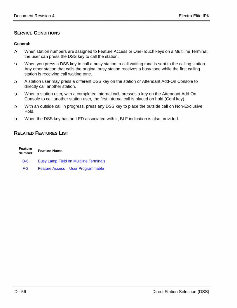
D - 56 Direct Station Selection (DSS)
___________________________________________________________________________________
___________________________________________________________________________________Document Revision 4 Electra Elite IPK
SERVICE CONDITIONS
General:
When station numbers are assigned to Feature Access or One-Touch keys on a Multiline Terminal, the user can press the DSS key to call the station.
When you press a DSS key to call a busy station, a call waiting tone is sent to the calling station. Any other station that calls the original busy station receives a busy tone while the first calling station is receiving call waiting tone.
A station user may press a different DSS key on the station or Attendant Add-On Console to directly call another station.
When a station user, with a completed internal call, presses a key on the Attendant Add-On Console to call another station user, the first internal call is placed on hold (Conf key).
With an outside call in progress, press any DSS key to place the outside call on Non-Exclusive Hold.
When the DSS key has an LED associated with it, BLF indication is also provided.
RELATED FEATURES LIST
Feature Number
Feature Name
B-6 Busy Lamp Field on Multiline Terminals
F-2 Feature Access – User Programmable
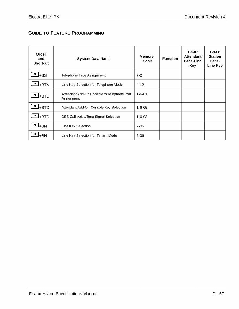
Electra Elite IPK Document Revision 4
Features and Specifications Manual D - 57
___________________________________________________________________________________
___________________________________________________________________________________
GUIDE TO FEATURE PROGRAMMING
Orderand
ShortcutSystem Data Name
Memory Block
Function
1-8-07AttendantPage-Line
Key
1-8-08StationPage-
Line Key
+BS Telephone Type Assignment 7-2
+BTM Line Key Selection for Telephone Mode 4-12
+BTDAttendant Add-On Console to Telephone Port Assignment
1-6-01
+BTD Attendant Add-On Console Key Selection 1-6-05
+BTD DSS Call Voice/Tone Signal Selection 1-6-03
+BN Line Key Selection 2-05
+BN Line Key Selection for Tenant Mode 2-06

D - 58 Direct Station Selection (DSS)
___________________________________________________________________________________
___________________________________________________________________________________Document Revision 4 Electra Elite IPK
THIS PAGE INTENTIONALLY LEFT BLANK

Features and Specifications Manual D - 59
___________________________________________________________________________________
___________________________________________________________________________________
Distinctive Ringing D-14
FEATURE DESCRIPTION
The Distinctive Ringing feature distinguishes between internal and incoming outside calls and provides distinct ring audible signals and patterns.
System Software allows Distinctive Ring Patterns to be assigned per outside CO line or per telephone.
SYSTEM AVAILABILITY
Terminal Type:
All Multiline Terminals
Required Components:
None
OPERATING PROCEDURES
None

D - 60 Distinctive Ringing
___________________________________________________________________________________
___________________________________________________________________________________Document Revision 4 Electra Elite IPK
SERVICE CONDITIONS
General:
Incoming outside and internal calls use flexible ringing tones and patterns.
Distinctive ringing patterns are as follows:
Internal ring tone has a pattern of 1 sec. On/2 sec. Off (default).
Incoming CO/PBX outside calls are assigned synchronous ring. The ringing pattern connected from the exchange to the CO/PBX/Centrex lines is repeated at all stations assigned to ring, except for Single Line Telephones connected to AP(R)-R Unit or APR-U Unit.
When synchronous ringing is disabled, an incoming CO call can be assigned to ring at one pattern and an incoming PBX/Centrex call can ring at a different pattern.
Incoming TIE/DID outside calls provide a distinctive ring pattern of 2 seconds ON/4 seconds OFF (system default).
Incoming TIE/DID is 0.25 sec. ON/0.25 sec. OFF (default).
AA transfer call is 0.5 sec. ON/0.5 sec. OFF (system default).
DIT/ANA calls to stations also provide Distinctive Ringing (Synchronous ring pattern).
Refer to the Electra Elite IPK Programming Manual for detailed in information about ringing patterns and ring tones.
Restrictions:
The transfer tone and pattern are used for the transferred calls regardless of the tone and pattern initially used by the trunk.
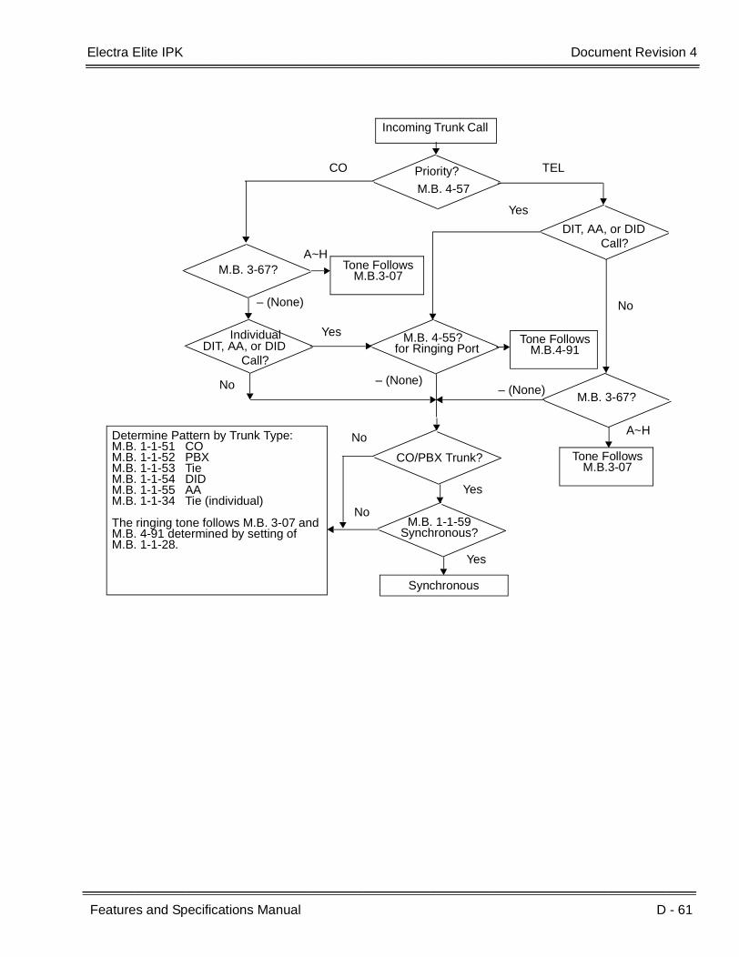
Electra Elite IPK Document Revision 4
Features and Specifications Manual D - 61
___________________________________________________________________________________
___________________________________________________________________________________
Incoming Trunk Call
Priority?
M.B. 4-57
Call?DIT, AA, or DID
M.B. 4-55?
M.B. 3-67?
CO TEL
Yes
No
Call?DIT, AA, or DID
– (None)
M.B. 3-67?
A~H
Yes
No
A~H
– (None)
Tone FollowsM.B.3-07
– (None)
Tone FollowsM.B.3-07
Tone FollowsM.B.4-91
Individualfor Ringing Port
CO/PBX Trunk?
M.B. 1-1-59Synchronous?
Synchronous
No
No
Yes
Yes
Determine Pattern by Trunk Type:M.B. 1-1-51 COM.B. 1-1-52 PBXM.B. 1-1-53 TieM.B. 1-1-54 DIDM.B. 1-1-55 AAM.B. 1-1-34 Tie (individual)
The ringing tone follows M.B. 3-07 and M.B. 4-91 determined by setting of M.B. 1-1-28.

D - 62 Distinctive Ringing
___________________________________________________________________________________
___________________________________________________________________________________Document Revision 4 Electra Elite IPK
GUIDE TO FEATURE PROGRAMMING
Orderand
ShortcutSystem Data Name
Memory Block
Function
1-8-07AttendantPage-Line
Key
1-8-08StationPage-
Line Key
+BTT CO Line Ringing Pattern Priority Selection 4-57
+BTT CO Line Ringing Pattern Selection for Telephone Mode
4-55
+BCT CO Line Ringing Pattern Selection for CO/PBX Line Mode
3-67
+BCS Synchronous Ringing Selection 1-1-59
+BTS Distinctive Ringing by Telephone or CO Selection
1-1-28
+BCT CO/PBX Ringing Variation Selection 3-07
+BTM Telephone Ringing Variation Selection 4-91
+BCS CO Line Ringing Pattern Selection 1-1-51
+BCS PBX Line Ringing Pattern Selection 1-1-52
+ALN Tie Line Delay Ring Pattern Selection 1-1-53
+BMCO/PBX Incoming Ringing Alarm Time Selection
1-1-06
+ALM Tie Line Delay Ringing Time Selection 1-1-07
+BCS CO Transfer Ring Pattern Selection 1-1-13
+BCS CO Transfer Ring Tone Selection 1-1-14
+BI Intercom Ring Tone Selection 1-2-20
When the system is at default this Memory Block must be programmed for the feature to be used.
Features and Specifications Manual D - 63
___________________________________________________________________________________
___________________________________________________________________________________
Do Not Disturb (DND) D-15
FEATURE DESCRIPTION
Do Not Disturb (DND) temporarily eliminates all audible signals for incoming calls to isolate the station from others in the system.
ENHANCEMENTS
With 2000 or higher, System Administration Terminal (SAT) software allows Do Not Disturb (DND) settings to be assigned and saved as part of the site database.
SYSTEM AVAILABILITY
Terminal Type:
All Stations
Required Components:
None
OPERATING PROCEDURES
To set Do Not Disturb using a Multiline Terminal:
1. Press A in idle mode.
2. Dial Access CodeFK.
3. Press A .
- OR -
Press the DND On/Off key.

D - 64 Do Not Disturb (DND)
___________________________________________________________________________________
___________________________________________________________________________________Document Revision 4 Electra Elite IPK
To set Do Not Disturb at any station:
1. Lift the handset or press E .
2. Dial DND set:DK(default).
3. Go on-hook or pressP.
To cancel Do Not Disturb using a Multiline Terminal:
1. Press A in idle mode.
2. Dial Access Code FI.
3. Press A .
- OR -
Press the DND ON/OFF key.
To cancel Do Not Disturb at any station:
1. Lift the handset or press E .
2. Dial DND cancel;DB(default).
3. Go on-hook or press E .
To cancel Call Forward - All Call and Do No Disturb System-Wide at Attendant Positions only:
1. Press A .
2. Dial Access CodeFH.
3. Press A .

Electra Elite IPK Document Revision 4
Features and Specifications Manual D - 65
___________________________________________________________________________________
___________________________________________________________________________________
SERVICE CONDITIONS
General:
The Do Not Disturb set and cancel Access Codes can be programmed on separate Feature Access or One-Touch keys. The DND set key LED (if equipped) does not light when DND is set.
When a station has a Do Not Disturb single ON/OFF key assigned, the LED lights when DND is set.
When a station user sets this feature, the associated red LED winks on any DSS/BLF key assigned for that station.
Transferred/Hold Recalls, Trunk Queues, Automatic Callback, and Barge-In override the DND setting.
Setting DND eliminates most audible signals that are sent through the speaker, including Voice Announcement. However, a call to this station can still be answered.
An incoming doorphone call overrides the DND mode allowing the doorphone chime to be heard.
Callback Request may be set to a Multiline Terminal in DND mode.
When DND is set, a Customized Message is displayed in the LCD (when equipped) of the Multiline Terminal. The user can select any of the 10 messages assigned in System Programming.
Internal calls to a station in DND result in a Call Waiting Tone. The LCD on the calling party Multiline Terminal displays a Customized Message indicating the called party is unavailable.
Restrictions:
Automatic Callback cannot be set to a station in DND mode.
When DND and Call Forward – All Call are set at the same time at a station, Call Forward – All Call takes priority.
Ring Transfer, Camp-On, and Tone Override cannot be set to a station that has DND set.

D - 66 Do Not Disturb (DND)
___________________________________________________________________________________
___________________________________________________________________________________Document Revision 4 Electra Elite IPK
RELATED FEATURES LIST
GUIDE TO FEATURE PROGRAMMING
Feature Number
Feature Name
C-7 Call Forward – All Call
C-27 Customized Message
P-1 PC Programming
Orderand
ShortcutSystem Data Name
Memory Block
Function
1-8-07AttendantPage-Line
Key
1-8-08StationPage-
Line Key
+BTS Class of Service (Attendant) Feature Selection 1 1-8-07 2-3
+BTS Class of Service (Station) Feature Selection 2 1-8-08 1-1
+BTT Station to Class of Service Feature Assignment 4-17

Features and Specifications Manual D - 67
___________________________________________________________________________________
___________________________________________________________________________________
Door Lock Release Relays D-16
FEATURE DESCRIPTION
The DPH(4)-U( ) ETU provides four doorphones and four Door Lock Release Relays. While a station user is talking to a Doorphone, an Access Code can be dialed to operate the relay associated with that Doorphone.
The time the door lock release is active depends on the digit code dialed.
SYSTEM AVAILABILITY
Terminal Type:
All Multiline Terminals
Required Components:
DPH(4)-U( ) ETU
DP-D-1A Doorphone
OPERATING PROCEDURES
While a Multiline Terminal is connected to a Doorphone:
1. Dial a single digit code B~I to control the door-to-lock release make time.
Make means shorted or closed.
2. Dial a single digit code A or Jto make the relay break again. This step is optional as the relay breaks after some time anyway (controlled in step 1).

D - 68 Door Lock Release Relays
___________________________________________________________________________________
___________________________________________________________________________________Document Revision 4 Electra Elite IPK
SERVICE CONDITIONS
General:
Relay make times are flexible.
The relay is controlled by the last entry. For example, 5 was dialed (8 seconds) then 9 is dialed. The relay should remain active for 15 more seconds.
Restrictions:
Door Lock Release Relays cannot be controlled by Single Line Telephones, PSII, or Wireless Telephones.
RELATED FEATURES LIST
Dial Time
2 2 seconds
3 4 seconds
4 6 seconds
5 8 seconds
6 10 seconds
7 12 seconds
8 14 seconds
9 15 seconds
1 Break (Open)
Break (Open)
Feature Number
Feature Name
D-17 Door/Monitor Telephone

Electra Elite IPK Document Revision 4
Features and Specifications Manual D - 69
___________________________________________________________________________________
___________________________________________________________________________________
GUIDE TO FEATURE PROGRAMMING
Orderand
ShortcutSystem Data Name
Memory Block
Function
1-8-07AttendantPage-Line
Key
1-8-08StationPage-
Line Key
+BN Card Interface Slot Assignment 7-1
+BTP Doorphone Assignment 1-7-00
+BTP Doorphone Display Time Selection 1-7-01
+BTP Doorphone Ring Pattern Selection 1-7-04
+BTP Doorphone Ringing Frequency Selection 1-7-05
+BTPDoorphone Chime Assignment (Day Mode)
4-03
+BCPDoorphone Chime Assignment (Night Mode)
4-04

D - 70 Door Lock Release Relays
___________________________________________________________________________________
___________________________________________________________________________________Document Revision 4 Electra Elite IPK
THIS PAGE INTENTIONALLY LEFT BLANK
Features and Specifications Manual D - 71
___________________________________________________________________________________
___________________________________________________________________________________
Door/Monitor Telephone D-17
FEATURE DESCRIPTION
The Electra Elite IPK system supports up to four Door/Monitor telephones. A doorphone can be called by a station user or a station (or number of stations) can be signaled when a doorphone call button is pressed. When a station answers the doorphone ringing, a 2-way speech path is established.
In addition to the doorphone ringing assignment, both the tone and cadence of doorphone ringing can be defined. This allows the station user to distinguish a doorphone call from any other call.
The Door/Monitor Telephone works closely with the Door Lock Release feature, and the DPH(4)-U( ) ETU that supports both features.
SYSTEM AVAILABILITY
Terminal Type:
All Multiline Terminals
Required Components:
DPH(4)-U( ) ETU
Up to four DP-D-1A Doorphones
OPERATING PROCEDURES
To call a Doorphone at a Multiline Terminal:
1. Lift the handset or press E .
2. Dial the desired Doorphone Access Code (default is not defined).
3. Door Lock Release can be controlled while you talk with the doorphone user.
D - 72 Door/Monitor Telephone
___________________________________________________________________________________
___________________________________________________________________________________Document Revision 4 Electra Elite IPK
To answer a Doorphone at a Multiline Terminal:
While the Multiline Terminal requiring doorphone is ringing, lift the handset or press E .
To answer a Doorphone that is ringing at another Multiline Terminal:
1. When the Doorphone Ringing is ringing at another station, dial the DP1, DP2, DP3, or DP4 Access Code for the specific doorphone that is ringing.
2. The Door Lock Release Relay can be controlled while you talk with the doorphone user.
SERVICE CONDITIONS
General:
Doorphones 1 and 3 share a speech path and doorphones 2 and 4 share a speech path. When a doorphone is busy, the speech path is busy. Ringing indication works, but the other doorphone cannot be answered until the speech path is idle.
Restrictions:
Doorphone Ringing cannot be assigned to Single Line Telephones, including those supported by analog port adapters.
Doorphone Ringing cannot be assigned to PSII or Wireless Telephones.
An incoming doorphone call overrides Do Not Disturb (DND) mode to allow the doorphone chime to be heard.
RELATED FEATURES LIST
Feature Number
Feature Name
D-16 Door Lock Release Relays

Electra Elite IPK Document Revision 4
Features and Specifications Manual D - 73
___________________________________________________________________________________
___________________________________________________________________________________
GUIDE TO FEATURE PROGRAMMING
Orderand
ShortcutSystem Data Name
Memory Block
Function
1-8-07AttendantPage-Line
Key
1-8-08StationPage-
Line Key
+BS Card Interface Slot Assignment 7-1
+BTP Doorphone Assignment 1-7-00
+BTP Doorphone Chime Assignment (Day Mode) 4-03
+BTP Doorphone Chime Assignment (Night Mode) 4-04
+BTP Doorphone Ring Pattern Selection 1-7-04
+BTP Doorphone Ringing Frequency Selection 1-7-05
+BTP Doorphone Display Assignment 1-7-01
When the system is at default this Memory Block must be programmed for the feature to be used.

D - 74 Door/Monitor Telephone
___________________________________________________________________________________
___________________________________________________________________________________Document Revision 4 Electra Elite IPK
THIS PAGE INTENTIONALLY LEFT BLANK
Features and Specifications Manual D - 75
___________________________________________________________________________________
___________________________________________________________________________________
DP to DTMF Switching D-18
FEATURE DESCRIPTION
DP to DTMF Switching is required for systems connected to Dial Pulse (DP) Tie lines that communicate with computers that require DTMF signaling.
SYSTEM AVAILABILITY
Terminal Type:
All Multiline Terminals
Required Components:
TLI(2)-U( ) ETU or DTI-U( ) ETU assigned to support Tie lines.
OPERATING PROCEDURES
To switch an outside call in progress on the Dial Pulse line:
1. Dial J and L.
2. Dial desired number.
SERVICE CONDITIONS
General:
After a DP line is switched to DTMF using an Access Code, the connection can be switched back to DP only by going on-hook.
DP/DTMF switching operations can be programmed as part of the Speed Dial program.
This feature is not required for DTMF Single Line Telephones. These telephones send their own DTMF signals over the voice path to the outside equipment.
D - 76 DP to DTMF Switching
___________________________________________________________________________________
___________________________________________________________________________________Document Revision 4 Electra Elite IPK
Code Restriction, Outgoing Restriction, and LCR are not bypassed when this feature is used.
Restrictions:
This operation can be performed only on Tie lines.
Dial Pulse Single Line Telephones cannot send DTMF signals, and cannot be used with this feature.
RELATED FEATURES LIST
GUIDE TO FEATURE PROGRAMMING
Feature Number
Feature Name
E-6 E&M Tie Lines (4-Wire)
Orderand
ShortcutSystem Data Name
Memory Block
Function
1-8-07AttendantPage-Line
Key
1-8-08StationPage-
Line Key
+BS Card Interface Slot Assignment 7-1
+BCT Trunk (Installed, DP/DTMF) Selection 3-92

Features and Specifications Manual D - 77
___________________________________________________________________________________
___________________________________________________________________________________
Drop Key D-19
FEATURE DESCRIPTION
The Drop Key abandons a call while retaining the PBX/Centrex line to originate another call. The Drop Key is provided by programming a Feature Access or One-Touch key. This feature allows the Recall key to be used to provide a hookflash to the PBX or Central office.
SYSTEM AVAILABILITY
Terminal Type:
All Multiline Terminals
Required Components:
None
OPERATING PROCEDURES
To program a Feature Access key as a Drop key:
1. Press A .
2. Press B .
3. Press the Feature Access key.
4. DialL.
5. DialE.
6. Press A .

D - 78 Drop Key
___________________________________________________________________________________
___________________________________________________________________________________Document Revision 4 Electra Elite IPK
To program a One-Touch key as a Drop key:
1. Press A .
2. Press B .
3. Press the One-Touch key.
4. DialL.
5. DialE.
6. Press A .
To use the Drop key from a Multiline Terminal with a CO/PBX call in progress:
1. Press the Feature Access or One-Touch key programmed as a Drop key.
2. Receive new CO/PBX dial tone.
3. Dial the desired number.
SERVICE CONDITIONS
General:
When on a CO/PBX call, you can press the Feature key and dial 5 to use the Drop key feature.
Restrictions:
The Drop key provides a timed disconnect signal on CO/PBX lines. The time of a disconnect signal is fixed at 1.5 seconds and cannot be changed by System Programming.
The Drop key cannot be used for internal, DID, or Tie line calls.

Electra Elite IPK Document Revision 4
Features and Specifications Manual D - 79
___________________________________________________________________________________
___________________________________________________________________________________
RELATED FEATURES LIST
GUIDE TO FEATURE PROGRAMMING
Feature Number
Feature Name
R-1 Recall Key
Orderand
ShortcutSystem Data Name
Memory Block
Function
1-8-07AttendantPage-Line
Key
1-8-08StationPage-
Line Key
+BN Line Key Selection 2-05
+BN Line Key Selection for Tenant Mode 2-06
+BTM Line Key Selection for Telephone Mode 4-12

D - 80 Drop Key
___________________________________________________________________________________
___________________________________________________________________________________Document Revision 4 Electra Elite IPK
THIS PAGE INTENTIONALLY LEFT BLANK

Features and Specifications Manual D - 81
___________________________________________________________________________________
___________________________________________________________________________________
Dterm ® Analog Cordless Terminal D-20
FEATURE DESCRIPTION
The NEC Dterm Analog Cordless terminal may be used with the Electra Elite IPK KTS. The DTR-1R-1 TEL terminal uses 2.4 GHz Digital Spread Spectrum (DSS) Technology and is connected to an analog port using SLI(4)/(8)-U( ) or OPX(2)-U( ) ETU, SLT(1)-U( ) ADP, or an APR-U Unit connected to a multiline terminal. This terminal does not have an LCD display.
The 2.4 GHz frequency range provides secure conversation with the clarity of digital sound and reduced interference. The operating range is 50 to 250 feet.
Depending on your environment, the maximum number of cordless devices used without interference varies.
Features include:
2.4 GHz Digital Spread Spectrum
30 Channel Autoscan
10-Number Memory DiaLing
Desk Or Wall-Mount Option
Tone/Pulse dialing
Handset Volume Control
32-Digit Redial
Page/Find
AutoTalk
AutoStandby AutoTalk and AutoStandby are trademarks of Uniden America Corp.
6-Hour Talk Time
7 Day Standby Time
Hearing Aid Compatible

D - 82 Dterm ® Analog Cordless Terminal
___________________________________________________________________________________
___________________________________________________________________________________Document Revision 4 Electra Elite IPK
SYSTEM AVAILABILITY
Terminal Type:
DTR-1R-1 TEL
OPERATING PROCEDURES
To connect Base Unit:
1. Connect the telephone line between the TEL LINE connector on the Base and a telephone outlet.
2. Connect AC Adapter between DC IN 9V connector on the Base and 120 VAC wall outlet.
3. Place the Base on a desktop/tabletop.
4. Place the handset on the Base.
5. Place the antenna vertical.
To answer a call:
When the telephone rings, remove the handset from the Base to access AutoTalk.
- OR -
When the handset is off the Base, press any key.
To place a call:
1. Remove the handset from the Base, and press talk.
2. The talk/battery low LED flashes green and is then on continuously.
3. Listen for dial tone.
4. Dial the number.

Electra Elite IPK Document Revision 4
Features and Specifications Manual D - 83
___________________________________________________________________________________
___________________________________________________________________________________
To hang up:
Return the handset to the base to access AutoStandby.
- OR -
When the handset is off the Base, press talk.
To redial:
1. Pick up the handset, and press talk.
2. Listen for dial tone.
3. Press redial to dial the last number called.
To store a pulse-dialed number in memory:
1. Remove the handset from the Base, and press memory. The talk/battery low LED flashes.
2. Enter the telephone number (up to 20 digits) to be stored.
3. Press memory, and enter the memory location (0~9) to be used for storage.
4. Listen for a long beep, and the talk/battery low LED goes off to indicate the number is stored.
When any key other than 0~9 is selected, the handset beeps rapidly to indicate that a number was not stored.
5. Log the number entered.
To enter a pause in memory dialing:
1. After entering the number to be stored in memory, press pause to enter a pause in the number sequence.
When pause is to be entered it counts as a digit, and the number can have only 19 digits.
2. Complete steps 3~5 of the memory store procedure.
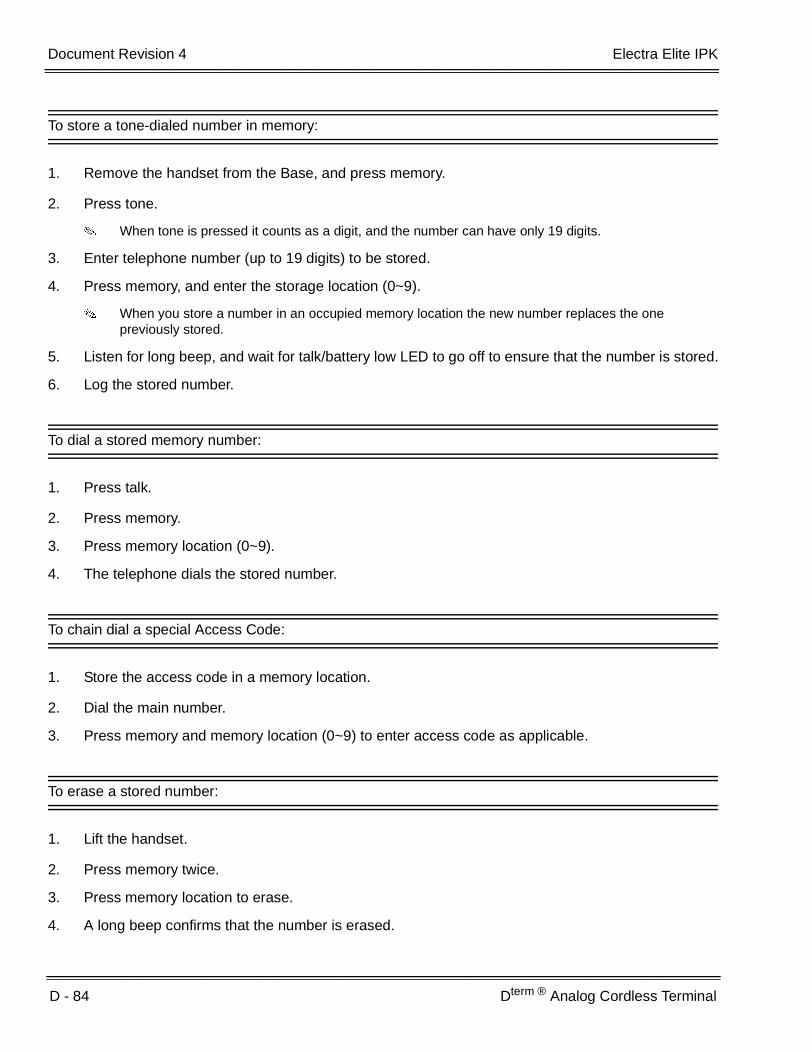
D - 84 Dterm ® Analog Cordless Terminal
___________________________________________________________________________________
___________________________________________________________________________________Document Revision 4 Electra Elite IPK
To store a tone-dialed number in memory:
1. Remove the handset from the Base, and press memory.
2. Press tone.
When tone is pressed it counts as a digit, and the number can have only 19 digits.
3. Enter telephone number (up to 19 digits) to be stored.
4. Press memory, and enter the storage location (0~9).
When you store a number in an occupied memory location the new number replaces the one previously stored.
5. Listen for long beep, and wait for talk/battery low LED to go off to ensure that the number is stored.
6. Log the stored number.
To dial a stored memory number:
1. Press talk.
2. Press memory.
3. Press memory location (0~9).
4. The telephone dials the stored number.
To chain dial a special Access Code:
1. Store the access code in a memory location.
2. Dial the main number.
3. Press memory and memory location (0~9) to enter access code as applicable.
To erase a stored number:
1. Lift the handset.
2. Press memory twice.
3. Press memory location to erase.
4. A long beep confirms that the number is erased.

Electra Elite IPK Document Revision 4
Features and Specifications Manual D - 85
___________________________________________________________________________________
___________________________________________________________________________________
Mute operation:
1. During a call, press mute to turn off the microphone.
2. To cancel mute, press mute or talk.
To select a different channel:
1. When interference interrupts a call, press channel.
2. The talk/battery low LED flashes to indicate that the telephone is switching to another channel.
Factory set channels (30) are provided for switching.
This feature operates only when the telephone is in use.
To access Call Waiting:
1. When you receive a call during conversation, press flash to access the new call.
2. Press flash to return to the previous call.
To use page/find feature to locate the handset:
1. Press page/find on the Base.
2. The handset beeps for five seconds.
3. Press and hold page/find for more than two seconds to get a continuous beep from the handset for one minute.
4. Hold page/find down for more than one minute, and the handset beeps until page/find is released.
5. Press talk to end the page.
6. Press talk again to make a call.
This feature does not work when the telephone is in use.

D - 86 Dterm ® Analog Cordless Terminal
___________________________________________________________________________________
___________________________________________________________________________________Document Revision 4 Electra Elite IPK
THIS PAGE INTENTIONALLY LEFT BLANK

Features and Specifications Manual D - 87
___________________________________________________________________________________
___________________________________________________________________________________
Dterm ® Cordless II Terminal D-21
FEATURE DESCRIPTION
The NEC Dterm Cordless II Terminal may be used with the Electra Elite IPK KTS. The DTR-4R-1 TEL uses 900 MHz Digital Spread Spectrum (DSS) Technology and must be connected in tandem to a Multiline Terminal.
Press the applicable key on the Base Unit to Switch between Cordless operation and Multiline Terminal operation.
SYSTEM AVAILABILITY
Terminal Type:
DTR-4R-1 TEL
FeatureDterm Cordless II
(DTR-4R-1)
Digital Technology 900 MHz Spread Spectrum
LCD 2 x 16
Silent Alarm Yes
Dedicated KeysTALK, TRANSFER, HOLD, CONF, CHAN, REDIAL, MUTE, R/VOL
Programmable Line Keys 4
Operational Range 50~350 feet
Message Waiting Indication Icon
Headset Connection Yes
Channels 10
Determined by environmental conditions.

D - 88 Dterm ® Cordless II Terminal
___________________________________________________________________________________
___________________________________________________________________________________Document Revision 4 Electra Elite IPK
OPERATING PROCEDURES
To program the Dterm Cordless II:
1. Press and hold down and #, then press TALK. The F1 LED flashes red.
2. Press R/VOL repeatedly to scroll through the line key (LK) and feature options for function key F1.
3. Press MUTE to select the displayed line key or feature.
4. When a Line Key is assigned, press MUTE once to enter the Off-Hook Ringing ON or OFF Mode. Press R/VOL to toggle between /TALK for ON or /NO TALK for OFF.
5. Press MUTE to advance to the next function key (F2 ~ F4).
6. After programming F4, press MUTE to advance to Global Off-Hook Ringing Assignment.
7. Press R/VOL to turn Global Off-Hook Ringing ON/OFF (LCD indicates ON or OFF).
8. Press TALK to exit.
Function keys F1 ~ F4 can be programmed as Line Keys 1~16, Redial (LNR/SPD), Answer (ANS), Feature (FNC), or Recall. When assigned, these keys operate the same as on an NEC Multiline Terminal.
When initially installed, function keys F1~F4 default to Line Keys 1~4 respectively and Off-Hook Ringing defaults to ON.
Global Off-Hook Ringing must be ON (default) for any Function key to work with Off-Hook Ringing.
To place an internal call:
1. Press TALK. icon is displayed.
2. Dial Station Number.
- OR -
Press (F1~F4) programmed for Direct Station Selection (DSS).
3. Announce call after tone burst or wait for call to be answered.
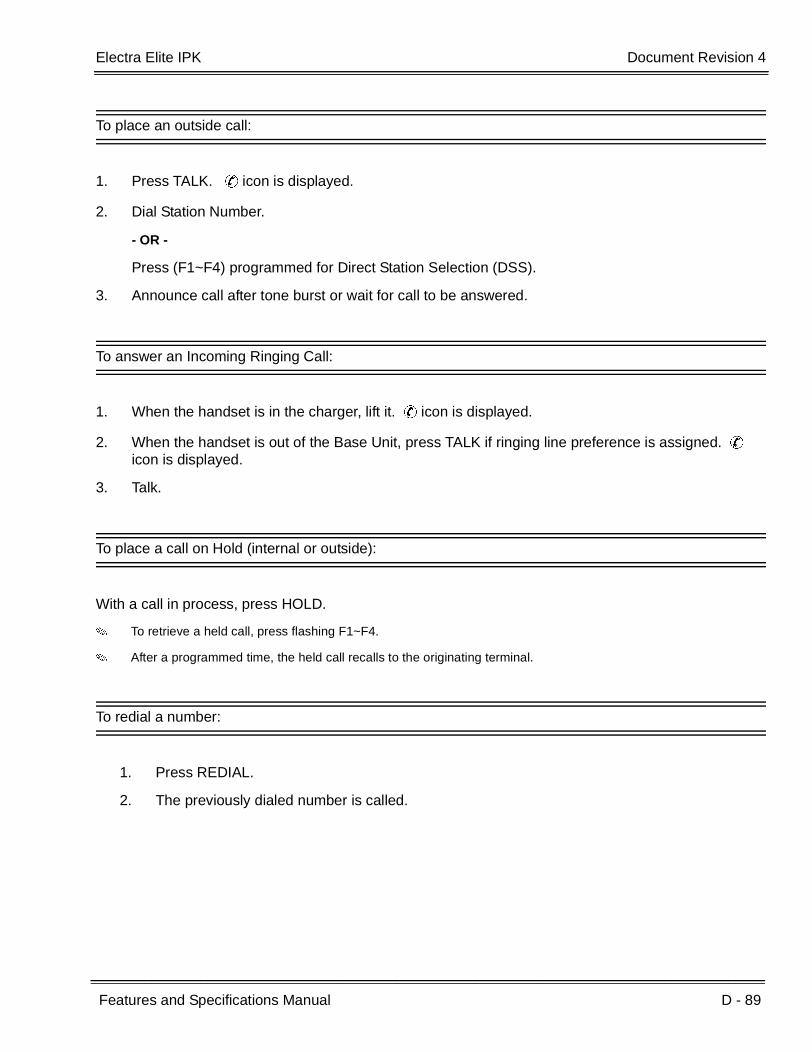
Electra Elite IPK Document Revision 4
Features and Specifications Manual D - 89
___________________________________________________________________________________
___________________________________________________________________________________
To place an outside call:
1. Press TALK. icon is displayed.
2. Dial Station Number.
- OR -
Press (F1~F4) programmed for Direct Station Selection (DSS).
3. Announce call after tone burst or wait for call to be answered.
To answer an Incoming Ringing Call:
1. When the handset is in the charger, lift it. icon is displayed.
2. When the handset is out of the Base Unit, press TALK if ringing line preference is assigned.
icon is displayed.
3. Talk.
To place a call on Hold (internal or outside):
With a call in process, press HOLD.
To retrieve a held call, press flashing F1~F4.
After a programmed time, the held call recalls to the originating terminal.
To redial a number:
1. Press REDIAL.
2. The previously dialed number is called.
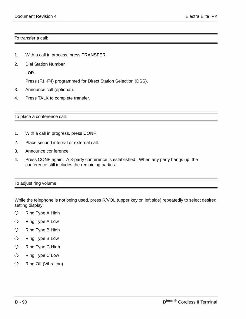
D - 90 Dterm ® Cordless II Terminal
___________________________________________________________________________________
___________________________________________________________________________________Document Revision 4 Electra Elite IPK
To transfer a call:
1. With a call in process, press TRANSFER.
2. Dial Station Number.
- OR -
Press (F1~F4) programmed for Direct Station Selection (DSS).
3. Announce call (optional).
4. Press TALK to complete transfer.
To place a conference call:
1. With a call in progress, press CONF.
2. Place second internal or external call.
3. Announce conference.
4. Press CONF again. A 3-party conference is established. When any party hangs up, the conference still includes the remaining parties.
To adjust ring volume:
While the telephone is not being used, press R/VOL (upper key on left side) repeatedly to select desired setting display:
Ring Type A High
Ring Type A Low
Ring Type B High
Ring Type B Low
Ring Type C High
Ring Type C Low
Ring Off (Vibration)
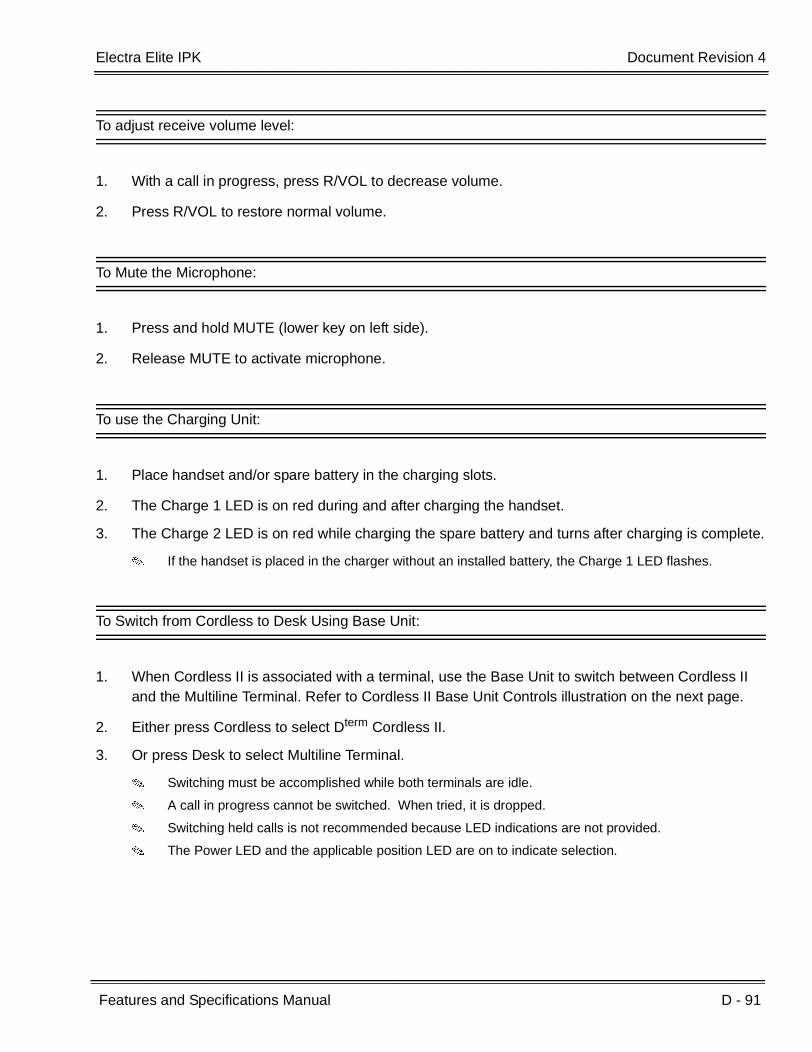
Electra Elite IPK Document Revision 4
Features and Specifications Manual D - 91
___________________________________________________________________________________
___________________________________________________________________________________
To adjust receive volume level:
1. With a call in progress, press R/VOL to decrease volume.
2. Press R/VOL to restore normal volume.
To Mute the Microphone:
1. Press and hold MUTE (lower key on left side).
2. Release MUTE to activate microphone.
To use the Charging Unit:
1. Place handset and/or spare battery in the charging slots.
2. The Charge 1 LED is on red during and after charging the handset.
3. The Charge 2 LED is on red while charging the spare battery and turns after charging is complete.
If the handset is placed in the charger without an installed battery, the Charge 1 LED flashes.
To Switch from Cordless to Desk Using Base Unit:
1. When Cordless II is associated with a terminal, use the Base Unit to switch between Cordless II and the Multiline Terminal. Refer to Cordless II Base Unit Controls illustration on the next page.
2. Either press Cordless to select Dterm Cordless II.
3. Or press Desk to select Multiline Terminal.
Switching must be accomplished while both terminals are idle.
A call in progress cannot be switched. When tried, it is dropped.
Switching held calls is not recommended because LED indications are not provided.
The Power LED and the applicable position LED are on to indicate selection.

D - 92 Dterm ® Cordless II Terminal
___________________________________________________________________________________
___________________________________________________________________________________Document Revision 4 Electra Elite IPK
To switch from Desk to Cordless using Redial Key:
1. Verify that the Base Unit is in Desk mode.
2. Remove battery.
3. Press and hold J and L on the handset.
4. Install the battery while holding these keys.
5. After the handset beeps one time, release the keys.
6. The handset is in Setup mode.
7. Press HOLD to display the current mode (Digital/Redial).
8. Press F2 and then HOLD.
9. The handset displays Digital (F8), and changes the REDIAL key program to Desk/Cordless Softkey Switching mode.
10. Press TALK to restore standby mode.
11. Press REDIAL to test this feature.
12. The Base Unit automatically changes from Desk to Cordless.
This is a one time operation, but one of the F1~F4 keys can be programmed for the redial function.
13. To restore the normal redial function, enter setup mode, and press F3 and HOLD to display Digital (Redial).
14. Press TALK to restore standby mode.
Cordless II Base Unit Controls
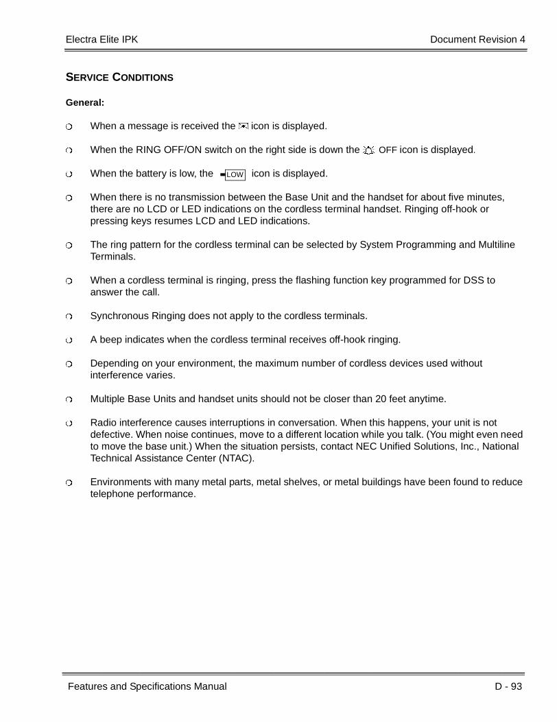
Electra Elite IPK Document Revision 4
Features and Specifications Manual D - 93
___________________________________________________________________________________
___________________________________________________________________________________
SERVICE CONDITIONS
General:
When a message is received the icon is displayed.
When the RING OFF/ON switch on the right side is down the OFF icon is displayed.
When the battery is low, the icon is displayed.
When there is no transmission between the Base Unit and the handset for about five minutes, there are no LCD or LED indications on the cordless terminal handset. Ringing off-hook or pressing keys resumes LCD and LED indications.
The ring pattern for the cordless terminal can be selected by System Programming and Multiline Terminals.
When a cordless terminal is ringing, press the flashing function key programmed for DSS to answer the call.
Synchronous Ringing does not apply to the cordless terminals.
A beep indicates when the cordless terminal receives off-hook ringing.
Depending on your environment, the maximum number of cordless devices used without interference varies.
Multiple Base Units and handset units should not be closer than 20 feet anytime.
Radio interference causes interruptions in conversation. When this happens, your unit is not defective. When noise continues, move to a different location while you talk. (You might even need to move the base unit.) When the situation persists, contact NEC Unified Solutions, Inc., National Technical Assistance Center (NTAC).
Environments with many metal parts, metal shelves, or metal buildings have been found to reduce telephone performance.
LOW

D - 94 Dterm ® Cordless II Terminal
___________________________________________________________________________________
___________________________________________________________________________________Document Revision 4 Electra Elite IPK
THIS PAGE INTENTIONALLY LEFT BLANK

Features and Specifications Manual D - 95
___________________________________________________________________________________
___________________________________________________________________________________
Dterm ® Cordless Lite II Terminal D-22
FEATURE DESCRIPTION
The NEC Dterm Cordless II Terminal may be used with the Electra Elite IPK KTS. The DTH-4R-( ) TEL uses 900 MHz FM with ADPCM (digital) Technology and is connected in tandem to a Multiline Terminal.
Press the applicable key on the Base Unit to Switch between Cordless operation and Multiline Terminal operation.
SYSTEM AVAILABILITY
Terminal Type:
DTH-4R-( ) TEL
FeatureDterm Cordless Lite II
(DTH-4R-1)
Digital Technology 900 MHz FM with ADPCM (digital)
LCD 2-line, 16-digit LCD Display
Silent Alarm Yes
Dedicated KeysTALK, TRANSFER, HOLD, CONF, CHAN, REDIAL, MUTE, R/VOL
Programmable Line Keys 4
Operational Range 50~150 feet
Message Waiting Indication Yes (Icon)
Headset Connection Yes
Channels 30
Determined by environmental conditions. These are cordless RF devices and, therefore, some interference may take place when operating in the same environment as other wireless devices which operate within the same frequency spectrum.

D - 96 Dterm ® Cordless Lite II Terminal
___________________________________________________________________________________
___________________________________________________________________________________Document Revision 4 Electra Elite IPK
REQUIRED COMPONENTS:
ESI(8)-U( ) ETU
- OR -
ESIB(8)-U( ) ETU
- OR -
ESIE(8)-U( ) Unit
OPERATING PROCEDURES
To set up and program the Dterm Cordless Lite II (DTH-4R-1):
1. Press and hold down and #, then press TALK. The F1 LED flashes red and F1=LK01 is displayed on the LCD.
2. Press Ring/Vol repeatedly to scroll through the line key (LK) and feature options for function key F1.
3. Press On/Off MUTE to select the displayed line key or feature.
4. When a Line key is assigned, press MUTE once to enter the Off-Hook Ringing ON or OFF Mode. Press Ring/Vol to toggle between TALK for On or NO TALK for Off.
TALK is selected when the F1~F4 function keys are programmed for CO or Call Appearance Keys. NO TALK is selected when F1~F4 function keys are programmed for functions not requiring an off-hook state (e.g., Log On/Off or DND.)
5. Press On/Off MUTE to advance to the next function key (F2 ~ F4).
6. After programming F4, press On/Off MUTE to advance to Global Off-Hook Ringing Assignment.
7. Press Ring/Vol to turn Global Off-Hook Ringing On or Off (LCD indicates ON or OFF as appropriate).
8. Press TALK to exit.
Function keys F1 ~ F4 can be programmed as Line Keys 1~16, Redial (LNR/SPD), Answer (ANS), Feature (FNC), or Recall. When assigned, these keys operate the same as on an NEC Multiline Terminal.
When initially installed, function keys F1~F4 default to Line keys 1~4 respectively and Off-Hook Ringing defaults to ON.
Global Off-Hook Ringing must be ON (default) for any function key to operate with off-hook ringing.

Electra Elite IPK Document Revision 4
Features and Specifications Manual D - 97
___________________________________________________________________________________
___________________________________________________________________________________
Switching Between the Desktop Multiline Telephone and the Dterm Cordless Lite Telephone Using the Base Unit:
When the Dterm Cordless Lite II is associated with a Multiline Telephone the following is applicable:
Switching between the cordless mode and desk mode must be done while both telephones are idle.
A call in progress can not be switched between the Dterm Cordless Lite II and the associated Multiline Telephone.
Switching held calls between the Dterm Cordless Lite II Telephone and the associated Multiline Telephone is not recommended because line key LED indications are not provided.
Switching from Multiline Telephone and Dterm Cordless Lite Telephone:
1. Press the Cordless button on the base unit.
- OR -
Press REDIAL key from the Dterm Cordless Lite II handset.
This applies only if the REDIAL key is programmed to perform desk to cordless switching.
To switch from Dterm Cordless Lite II Telephone to Multiline Telephone:
1. Press the DESK button on the base unit.
For additional Operating Procedures, refer to the Dterm Cordless Lite II (DTH-4R-1) Owner’s Guide.
SERVICE CONDITIONS
General:
When the Dterm Cordless Lite II can be used in conjunction with the Electra Elite, Electra Elite IPK, and Dterm Series E and Series i Digital Multiline Telephones.
Battery Capacity is 700 mAh, 3.6V with a Talk Mode of six hours (typical) and a Standby Mode of five days (typical).
The battery can be hot swapped while on a call. The battery must be replaced with another charged battery pack within 20 seconds, otherwise the connection is lost.

D - 98 Dterm ® Cordless Lite II Terminal
___________________________________________________________________________________
___________________________________________________________________________________Document Revision 4 Electra Elite IPK
The handset has visual and audible indicators to warn of a low battery condition.
When a message is received, the message icon is displayed.
Synchronous Ringing does not apply to the cordless terminals.
A beep indicates when the cordless terminal receives off-hook ringing.
Restrictions:
A spare battery is available as an Optional Available Part. A second battery is not shipped with the product.
The battery can be charged only when it is installed in the handset and the handset is in the charger. A stand-alone battery charger is not available.
Environments with many metal parts, metal shelves, or metal buildings have been found to reduce telephone performance.
When multiple cordless telephones are used in your office, they must operate on different channels and be at least 20 feet apart (including the base unit and the telephones).
RELATED FEATURE LIST
GUIDE TO FEATURE PROGRAMMING
Feature Number
Feature Name
C-26 Cordless Telephone Connection
D-20 Dterm ® Analog Cordless Terminal
Orderand
ShortcutSystem Data Name
Memory Block
Function
1-8-07Attendant
Page-Line Key
1-8-08StationPage-
Line Key
+BS Telephone Type Assignment 7-2
+BTM Line Key Selection for Telephone Mode 4-12

Features and Specifications Manual D - 99
___________________________________________________________________________________
___________________________________________________________________________________
Dterm ® Handset Cordless D-23
FEATURE DESCRIPTION
The Dterm Handset Cordless Terminal is a stand-alone telephone with a direct connection to one digital port on the ESI(8)-U( ) ETU.
The Dterm Handset Cordless Terminal has the following features:
40 separate Channels for Base unit communication
3-Channel semi-auto scan (MCA)
900 MHz Analog FM spectrum with Voice Scramble
MW Lamp for incoming call and voice mail message notification
30-100 foot operating range between Handset and Base unit without obstructions or other environmental factors
Auto Talk Feature
Any Key Answer
LED Low Battery Warning
Talk (Talk), Transfer (Trf), Mute (Mute), Channel (Ch), Volume (Vol), and Ringer On/Off keys
4-hour Talk Time
40-hour Standby Time
SYSTEM AVAILABILITY
Terminal Type:
DTP-16HC-1 TEL
AC(A)-U Power Adapter

D - 100 Dterm ® Handset Cordless
___________________________________________________________________________________
___________________________________________________________________________________Document Revision 4 Electra Elite IPK
OPERATING PROCEDURES
All Operating Procedures assume these features are assigned to the DTP-16HC-1 terminal:
Prime Line Pickup to the Primary Extension
Ringing Line Preference
To change the Auto Talk mode:
1. Hold down Trf key while changing the Ringer On/Off switch from Off to On.
2. When mode changes a confirmation tone is generated:Auto Talk Off: 3 BeepsAuto Talk On: 2 Beeps
Answering calls:
1. When the Handset is on the Base Unit, only the Base Unit rings and the Large LED flashes as usual.
2. When in Standby mode, the handset and Base Unit both ring and the message waiting LED flashes rapidly in conjunction with the Base Unit Talk/Batt.low LED.
When Ringer On/Off switch is in Off mode, the Handset does not ring, but the message waiting LED flashes.
With Auto Talk off:
1. When the Handset is on the Base Unit, lift it and press any key.
2. The Talk/Batt.low LED flashes then lights continuously to indicate established communication path between the Handset and the Base Unit.
3. Talk to the caller. The Message waiting LED is Off.
4. When finished, press the Talk key or place Handset back in the Base Unit to disconnect the call.

Electra Elite IPK Document Revision 4
Features and Specifications Manual D - 101
___________________________________________________________________________________
___________________________________________________________________________________
With Auto Talk On:
1. When the Handset is on the Base Unit, lift it.
2. The Talk/Batt.low LED flashes then lights continuously to indicate established communication path between the Handset and the Base station.
3. Talk to the caller. The Message waiting LED is Off.
4. When finished, press the Talk key or place Handset back in the Base Unit to disconnect the call.
In Auto Standby, the Talk key does not have to be pressed to disconnect. Place the Handset in the Base Unit to disconnect the call.
5. After call is disconnected the Message Waiting LED becomes active again when messages are waiting.
Setting handset ringer On/Off Volume in Standby Mode:
1. Press Vol key to adjust volume normal or high.
2. While Vol is pressed, the ringer starts to ring based on the current setting.
Ringer Volume can be adjusted with Ringer On/Off key in Off.
To Adjust Receiver Volume with a call in progress:
Press the Vol key repeatedly to adjust from Medium High Low Normal in this order.
When call is disconnected, default volume returns to Normal.
To Mute Handset to disable the microphone:
1. Press Mute key.
2. The Talk/Batt.low Led Blinks 500 msec On, 500msec Off during Mute.
3. Press Mute again to reactivate the microphone.
Voice is not transmitted during Mute.
D - 102 Dterm ® Handset Cordless
___________________________________________________________________________________
___________________________________________________________________________________Document Revision 4 Electra Elite IPK
To make a call with Auto Talk Off:
1. Lift the Handset from the Base Unit.
2. Press Talk key.
3. The Talk/Batt.low LED flashes then lights continuously to indicate an established communication path between the Handset and the Base Unit and dial tone is generated.
4. Dial the number.
5. Talk to the party.
6. When finished, press the Talk key or place Handset back in the Base Unit to disconnect the call.
To make a call with Auto Talk On:
1. Lift the Handset from the Base Unit.
2. The Talk/Batt.low LED flashes then lights continuously to indicate established communication path between the Handset and the Base Unit and dial tone is generated.
3. Dial the number.
4. Talk to the party.
5. When finished, press the Talk key or place Handset back in the Base Unit to disconnect the call.
To Hold a call in progress at the Base Unit:
1. Press Hold and return the Handset to the Base Unit.
2. To return to the held party press the flashing green line key and press Talk or pick up the Handset.
After a programmed time, the held call recalls to the originating terminal.

Electra Elite IPK Document Revision 4
Features and Specifications Manual D - 103
___________________________________________________________________________________
___________________________________________________________________________________
To Hold a call in progress at the handset:
1. Press Trf.
2. An Internal Dial tone is generated.
3. To return to the held party press the flashing green line key.
After a programmed time the held call recalls to the originating terminal.
To establish a conference call at the Base Unit:
1. With a call in progress, press Conf on the Base Unit.
2. Dial another station number.
3. Announce Conference (Optional).
4. Press Conf on the Base Unit to establish the conference.
To Install the battery:
1. Slide the battery compartment cover on the lower Handset back down to remove it.
2. Remove the IMPORTANT charging NOTE from the battery compartment.
3. Align the guides on the bottom of the battery plug and insert it in the connector.
4. Put the battery in the compartment with the description visible.
5. Replace and push up the cover to snap it in place.
Ensure that the wires are inside the cover.
To install the belt clip:
1. Position clip to the back side of the Handset unit with the clip spring pointed up.
2. Align the four prongs of the clip to the four slots on the sides of the Handset.
3. Gently press belt clip to snap the prongs into place.

D - 104 Dterm ® Handset Cordless
___________________________________________________________________________________
___________________________________________________________________________________Document Revision 4 Electra Elite IPK
SERVICE CONDITIONS
General:
The Handset Cordless terminal provides 40 different channels for communication with the Base Unit.
When communication is stopped for about 30 seconds during handset conversation, the Handset Cordless terminal automatically searches for a clear channel. An error tone rings the handset when it is not on the Base Unit.
When reception becomes garbled or static occurs during conversation, channels can be changed manually. Press the Ch key to activate the 3-channel automatic scan (MCA). When channel change fails, an error tone is generated and the channel does not change. While the channel is changing, the Talk/Batt.low LED flashes (On 100 msec., Off 100 msec.).
When a communication path is established between the Handset Cordless terminal and the Base Unit, the Talk/Batt.low LED is on and dial tone is generated.
When a communication path cannot be established in 5 sec., an error tone is generated and the Handset returns to standby.
A pencil eraser or contact cleaner should be used monthly to clean the battery contacts on the Handset and Base Unit to maintain stable charge.
When the battery is low during standby, the Talk/Batt.low LED blinks (On 50 msec., Off 50 msec.).
When the battery is low during a call, an alarm tone is generated, and the Talk/Batt.low LED blinks (On 50 msec., Off 50 msec.). The Handset must be returned to the Base Unit.
The battery is charged by the line voltage.
Restrictions:
Only one Handset Cordless terminal can be connected per ESI port.
A provided RF line cord should be used for best performance.
The Handset Cordless is a stand-alone terminal.
Base units of the Handset Cordless terminals should be installed at least 17 feet apart for optimum performance. The distance range between the Base Unit and the handset is 30~100 feet without obstructions, depending on the environment.
Distance of DTP-16HC-1 from the switch is 60 Meters (197 Feet). Condition is less than 10 ohms loop resistance. Maximum distance when ACA-U Unit is connected, is 330 meters (1,083 Feet). Condition is less than 57 ohms loop resistance.
The Handset does not ring when the battery is low.
Electra Elite IPK Document Revision 4
Features and Specifications Manual D - 105
___________________________________________________________________________________
___________________________________________________________________________________
The standard charged nickel-cadmium battery may last four hours for conversation and 40 hours for standby. Initially the battery must be charged without interruption for 17.5 hours. The charge LED (below the Base Unit contacts) is red during charging and remains on after charging is completed.
After continuous charging, the Handset battery may fail to charge or discharge quickly. In either case, operate the Handset until the low battery alarm sounds, auto shutoff occurs, and the battery is fully discharged. Charge the battery without interruption for 17.5 hours. When the battery no longer charges, replace it.
The ACA-U Unit is the only adapter that can be used for the Handset Cordless Terminal.
Using the ACA-U Unit minimizes normal display blanking when the cordless handset is returned to the Base Unit.
The Dterm Handset Cordless is not wall mountable.
Depending on your environment, the maximum number of cordless devices used without interference varies.
Multiple base and handset units should not be closer than 20 feet anytime.
Radio interference causes interruptions in conversation. When this happens, your unit is not defective. When noise continues, move to a different location while you talk. (You might even need to move the Base Unit.) When the situation persists, contact NEC Unified Solutions, Inc., National Technical Assistance Center (NTAC).
Data Assignment:
The Ring Pattern for the Handset can be selected in System Programming.

D - 106 Dterm ® Handset Cordless
___________________________________________________________________________________
___________________________________________________________________________________Document Revision 4 Electra Elite IPK
THIS PAGE INTENTIONALLY LEFT BLANK

Features and Specifications Manual D - 107
___________________________________________________________________________________
___________________________________________________________________________________
Dterm ® IP Gateway System D-24
FEATURE DESCRIPTION
The Dterm IP Gateway system converts traditional voice traffic and its accompanying signaling for call setup and networking to IP for transport across a managed IP network. The system allows users at branch offices or telecommuters to take advantage of the rich feature set of the company central site Key Telephone System as though they were connected locally without loss of functionality. Traditional voice traffic (plus call setup and networking signaling) travel from the KTS to the Gateway where they are converted to IP packets that are shipped to a 10 Mb (Gateway) or 10/100 (Gateway II) Ethernet LAN port. They are then picked up by the enterprise router and sent to the Corporate WAN.
At the branch office, the local router receives the WAN signals and feeds them to the local 10/100 LAN. From there they reach the Dterm IP Branch unit that converts the IP packets back to standard (TDM) voice signals for distribution to attached Dterm Series E/Electra Elite telephones. The Dterm IP Branch supports up to 12 voice circuits. When the remote site is a telecommuter at home or only a few users, the remote IP/TDM conversion is performed by a Dterm IP Adapter that fits easily on the bottom of a standard Dterm Series E telephone.
This system:
supports circuit-/packet-based Networks
allows mix and match IP-capable EXTender clients up to eight or 12 users
connects to the digital-line side of the Electra Elite KTS
allows virtual configuration, management, and troubleshooting of EXTender clients from a central location
allows synchronous transmission
supports an asynchronous Terminal Adapter (TA)
allows encrypted user name and password on each port
supports call suspend mode on ISDN line with Asynchronous TA
supports IP Precedence and DiffServ QoS mechanisms
allows choice of network topologies and variable compression rates

D - 108 Dterm ® IP Gateway System
___________________________________________________________________________________
___________________________________________________________________________________Document Revision 4 Electra Elite IPK
SOFTWARE SUPPORT
TCP/IP protocol supports IP traffic and management.
RVPoIP uses UDP/IP protocol for voice transmission.
Serial RVP uses HDLC encapsulation for voice transmission.
Management and utilities include Telnet, inband RVP, RS-232 console interface (Gateway and Branch), SNMP, and HTML.
Software upgradable, using FTP, between the Gateway and the branch, RS-232 serial port to PC, or inband connection.
SYSTEM AVAILABILITY
Terminal Type:
DTU/DTP/DTR Multiline Terminals
DTP-32DE-1 for home environment
REQUIRED COMPONENTS
Components include the following:
Electra Elite IPK KTS with 1 ESI port for each Branch port and IP Adapter
Gateway unit
Branch unit and/or IP Adapters with total ports not exceeding the number of ports supported by the Gateway unit
Power Cord
RS-530 cable
2 RJ-21 50 pin cables to connect Gateway to DTS and Branch to punch block – connectors required include a female connector to attach to Dterm IP, and a male connector to attach to the KTS.
Punch blocks that can crossconnect the Dterm IP Gateway to the KTS and Dterm telephones to the branch locations
Installation hardware for Gateway and Branch units
System Administrator’s Guide
Quick Installation Guide
Application Guide
PC for configuration

Electra Elite IPK Document Revision 4
Features and Specifications Manual D - 109
___________________________________________________________________________________
___________________________________________________________________________________
T1, Fractional T1, ISDN, Frame Relay or ATM circuit that can connect the Branch unit to the Gateway location
A networking terminating device that can interface with the Gateway and Branch/Adapter units and support synchronous serial protocol using RS-232, V.35, or RS-530 interface, or 10BaseT Ethernet for an IP connection
NETWORK REQUIREMENTS
The Gateway must be installed on an existing LAN or WAN network.
Each unit requires a network device that supports a synchronous serial interface or an Ethernet connection to a TCP/IP network.
The network must be operational and active to complete installation of the Gateway.
The network device must support one of the following:
Synchronous serial signaling on its data port using an RS-232, V.35, or RS-530 interface
10BaseT Ethernet connection
OPERATING PROCEDURES
Same as Multiline Terminal
SERVICE CONDITIONS
General:
Refer to Dterm IP Gateway System Administrator’s Guide or Dterm IP Gateway II System Administrator’s Guide for more information.
TAPI is not supported.
Restrictions:
When you dial 911 on your Dterm telephone, the 911 facility reached is the one that serves the Gateway facility. To reach the correct 911 service for your area, use a telephone connected locally. The Dterm IP Branch unit provides an analog port for local dialing.
Synchronous ringing does not work on the remote telephone. Incoming trunk calls automatically ring 2 seconds on/2 seconds off.
Analog Fax machines and modems cannot operate with a Dterm Multiline Terminal that is connected to an APR-U Unit or AP(A)-R Unit optional adapter.
The CT(A)-R Unit, CTA-U Unit, or CTU(S)-U Unit cannot be installed to a KTS remote Multiline Terminal to provide TAPI functionality with the KTS.

D - 110 Dterm ® IP Gateway System
___________________________________________________________________________________
___________________________________________________________________________________Document Revision 4 Electra Elite IPK
The DTP-32DE-1 Multiline Terminal is the only one certified for use in a home environment. None of the other Dterm Series E or Electra Elite Multiline Terminals are certified for home use because of FCC restrictions, but they are approved for use in an office environment.
The HFU-U/HF-R Unit handsfree adapter cannot operate with a KTS remote Multiline Terminal for home use because of FCC restrictions, but it is approved for use in an office environment.
An applicable network terminating device must be installed and functioning at both the corporate facility and the branch office.
The data connection between the corporate facility and the branch office must be configured properly and operational.
Network termination equipment must support an RS-232, V.35 or RS-530 synchronous interface or support IP devices over Ethernet.
The system operates from 100-240 VAC, 50-60 Hz. Power must not be applied to the Gateway unit until specified in the installation procedures.
The Gateway power supply and cables should be installed away from high power/high RF noise devices such as computers, fans, fluorescent ballast, or power supplies.
Good wiring practices are required. Do not run wires across devices such as fluorescent lights, computers, or air conditioners to avoid introducing noise in the modems.
The distance between the PBX/KTS and the Gateway unit must not exceed 500 feet.
When 5-, 6-, or 7-digit station numbers are used, this feature is not available.

Features and Specifications Manual E - 1
___________________________________________________________________________________
___________________________________________________________________________________
Elapsed Call Time E-1
FEATURE DESCRIPTION
The Elapsed Call Time displays how long the station has been connected to an outside line on Multiline Terminals with an LCD.
SYSTEM AVAILABILITY
Terminal Type:
All Multiline Terminals with an LCD
Required Components:
Not applicable
OPERATING PROCEDURES
None
SERVICE CONDITIONS
General:
The elapsed call time is shown on the LCD when a Multiline Terminal user is talking on an outside line.
The maximum Elapsed Call Time is 99 minutes and 59 seconds. When the time reaches this maximum, the display resets to 00 minutes and 00 seconds.
When a call is placed on hold (Exclusive or Non-Exclusive) or Transfer Recall, the Elapsed Call Time continues.
When a transferred call is answered, the Elapsed Call Time is reset to 00:00.
For outgoing CO/PBX calls, the starting time is set at 20 seconds (default) after the last digit is dialed. For incoming outside calls, the starting time is immediate. However, there is a 5-second delay after the call is answered.

E - 2 Elapsed Call Time
___________________________________________________________________________________
___________________________________________________________________________________Document Revision 4 Electra Elite IPK
The starting time for outgoing Tie line calls is when the called party answers the call.
The Elapsed Call Time display clears during dialing and returns five seconds after the last digit is dialed.
The Elapsed Call Time for each outside line operates independently. When several outside calls have been made from a station, the LCD displays the elapsed time when talking on each individual call.
During a 2-line conference call, the LCD displays the elapsed time of the last individual line call.
The Elapsed Call Time display clears when a Tone Override is received.
During a conference call that includes one outside party and two internal parties, the Elapsed Call Time shows on the display of the two internal parties.
GUIDE TO FEATURE PROGRAMMING
Orderand
ShortcutSystem Data Name
Memory Block
Function
1-8-07AttendantPage-Line
Key
1-8-08StationPage-
Line Key
+BMStart Time Selection This memory block applies only to
Copper Trunks.
1-1-05
+ACStation to Timer Class of Service Ports 1 and 2 are in Class 1 by default.
All other ports are in Class 2 by default.
4-71
Features and Specifications Manual E - 3
___________________________________________________________________________________
___________________________________________________________________________________
Electra Elite IPK Terminals E-2
FEATURE DESCRIPTION
The Electra Elite IPK Terminals provide ergonomic form and user-friendly functions. With advanced digital circuitry, the IPK Terminals consists of distinct models to meet diverse user telephone terminal needs.
ENHANCEMENT(S)
Release 3000:
With R3000 or higher, the LCD Name Assignment of Feature Access keys on DTH-16LD-1 telephones can be user programmed.
SYSTEM AVAILABILITY
Terminal Type:
DTH-16LD-1 TELDTH-32D-1 TELDTH-16D-1 TELDTH-8D-1 TELDTH-8-1 TELDCR-60-1 CONSOLE
(IP) ITH-16D-2 TEL ITH-8D-2 TEL
Required Components:
ESI(8)-U( ) ETUESIB(8)-U( ) ETUESIE(8)-U( ) UNIT
(IP) IPD(4/8)-U( ) ETU (for IP Terminals)
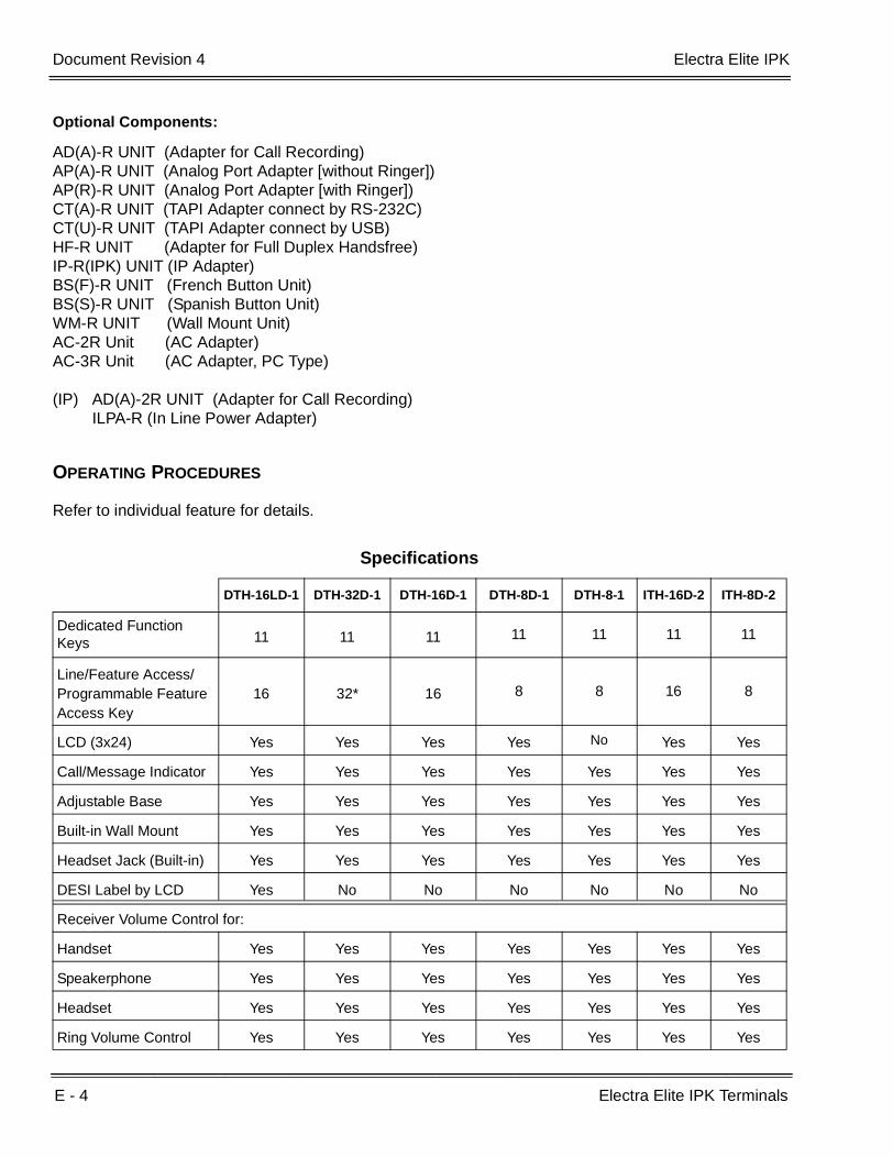
E - 4 Electra Elite IPK Terminals
___________________________________________________________________________________
___________________________________________________________________________________Document Revision 4 Electra Elite IPK
Optional Components:
AD(A)-R UNIT (Adapter for Call Recording)AP(A)-R UNIT (Analog Port Adapter [without Ringer])AP(R)-R UNIT (Analog Port Adapter [with Ringer])CT(A)-R UNIT (TAPI Adapter connect by RS-232C)CT(U)-R UNIT (TAPI Adapter connect by USB)HF-R UNIT (Adapter for Full Duplex Handsfree) IP-R(IPK) UNIT (IP Adapter)BS(F)-R UNIT (French Button Unit)BS(S)-R UNIT (Spanish Button Unit)WM-R UNIT (Wall Mount Unit)AC-2R Unit (AC Adapter)AC-3R Unit (AC Adapter, PC Type)
(IP) AD(A)-2R UNIT (Adapter for Call Recording)ILPA-R (In Line Power Adapter)
OPERATING PROCEDURES
Refer to individual feature for details.
Specifications
DTH-16LD-1 DTH-32D-1 DTH-16D-1 DTH-8D-1 DTH-8-1 ITH-16D-2 ITH-8D-2
Dedicated Function Keys 11 11 11 11 11 11 11
Line/Feature Access/Programmable Feature Access Key
16 32* 16 8 8 16 8
LCD (3x24) Yes Yes Yes Yes No Yes Yes
Call/Message Indicator Yes Yes Yes Yes Yes Yes Yes
Adjustable Base Yes Yes Yes Yes Yes Yes Yes
Built-in Wall Mount Yes Yes Yes Yes Yes Yes Yes
Headset Jack (Built-in) Yes Yes Yes Yes Yes Yes Yes
DESI Label by LCD Yes No No No No No No
Receiver Volume Control for:
Handset Yes Yes Yes Yes Yes Yes Yes
Speakerphone Yes Yes Yes Yes Yes Yes Yes
Headset Yes Yes Yes Yes Yes Yes Yes
Ring Volume Control Yes Yes Yes Yes Yes Yes Yes
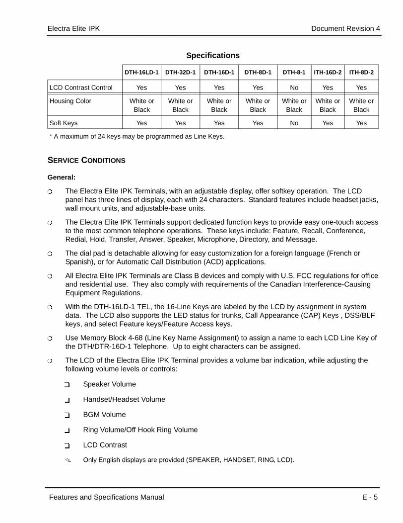
Electra Elite IPK Document Revision 4
Features and Specifications Manual E - 5
___________________________________________________________________________________
___________________________________________________________________________________
SERVICE CONDITIONS
General:
The Electra Elite IPK Terminals, with an adjustable display, offer softkey operation. The LCD panel has three lines of display, each with 24 characters. Standard features include headset jacks, wall mount units, and adjustable-base units.
The Electra Elite IPK Terminals support dedicated function keys to provide easy one-touch access to the most common telephone operations. These keys include: Feature, Recall, Conference, Redial, Hold, Transfer, Answer, Speaker, Microphone, Directory, and Message.
The dial pad is detachable allowing for easy customization for a foreign language (French or Spanish), or for Automatic Call Distribution (ACD) applications.
All Electra Elite IPK Terminals are Class B devices and comply with U.S. FCC regulations for office and residential use. They also comply with requirements of the Canadian Interference-Causing Equipment Regulations.
With the DTH-16LD-1 TEL, the 16-Line Keys are labeled by the LCD by assignment in system data. The LCD also supports the LED status for trunks, Call Appearance (CAP) Keys , DSS/BLF keys, and select Feature keys/Feature Access keys.
Use Memory Block 4-68 (Line Key Name Assignment) to assign a name to each LCD Line Key of the DTH/DTR-16D-1 Telephone. Up to eight characters can be assigned.
The LCD of the Electra Elite IPK Terminal provides a volume bar indication, while adjusting the following volume levels or controls:
Speaker Volume
Handset/Headset Volume
BGM Volume
Ring Volume/Off Hook Ring Volume
LCD Contrast
Only English displays are provided (SPEAKER, HANDSET, RING, LCD).
LCD Contrast Control Yes Yes Yes Yes No Yes Yes
Housing Color White or Black
White or Black
White or Black
White or Black
White or Black
White or Black
White or Black
Soft Keys Yes Yes Yes Yes No Yes Yes
* A maximum of 24 keys may be programmed as Line Keys.
Specifications
DTH-16LD-1 DTH-32D-1 DTH-16D-1 DTH-8D-1 DTH-8-1 ITH-16D-2 ITH-8D-2

E - 6 Electra Elite IPK Terminals
___________________________________________________________________________________
___________________________________________________________________________________Document Revision 4 Electra Elite IPK
The MIC Key controls the built-in microphone during speakerphone mode and controls the handset mute feature during handset/headset operation.
The DIR Key performs the same function as the Caller ID Scroll Key.
The MSG Key acts as a VM access key to call the VM pilot number.
The distance from the KSU for IPK Multiline Terminals (DTH type) can be extended when local AC power is provided. When the IPK Terminal is powered by a local AC-R Unit (AC Adapter), a built-in Long Line Adapter allows these telephones to be connected up to a distance of 2000 feet by Twisted 1-Pair Cable at 24 AWG.
Restrictions:
For compatibility of Adapter Units and Terminals, refer to the following table:
Terminal
Adapter Unit DTH-16LD-1 DTH-32D-1 DTH-16D-1 DTH-8D-1 DTH-8-1 ITH-16D-2 ITH-8D-2
AD(A)-R X X X X X – –
AP(A)-R X X X X X – –
AP(R)-R X X X X X – –
CT(A)-R X X X X X – –
CT(U)-R X X X X X – –
HF-R X X X X X – –
IP-R(IPK) X X X X – – –
Button Units
BS(F)-R( ) UNIT X X X X X X X
BS(S)-R( ) UNIT X X X X X X X
Other
WM-R UNIT X X X X X X X
AC-R UNIT X X X X X X X
IP Telephone Adapters
AD(A)-2R UNIT – – – – – X X
ILPA-R – – – – – X X
X = Comparable
– = Not comparable
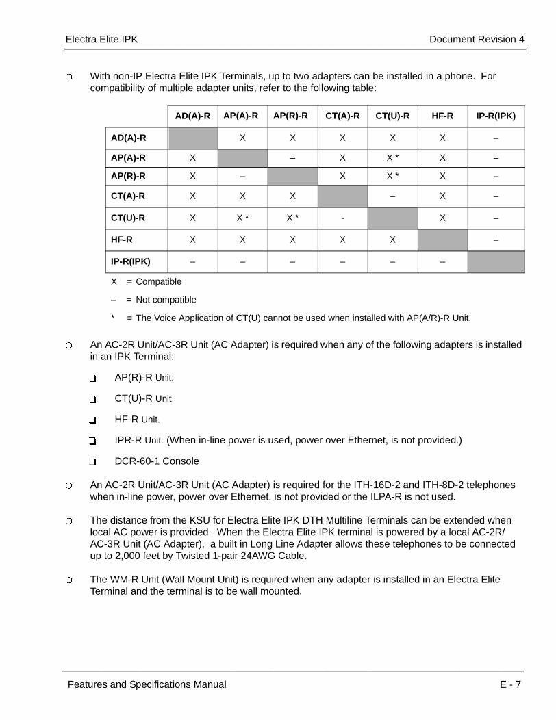
Electra Elite IPK Document Revision 4
Features and Specifications Manual E - 7
___________________________________________________________________________________
___________________________________________________________________________________
With non-IP Electra Elite IPK Terminals, up to two adapters can be installed in a phone. For compatibility of multiple adapter units, refer to the following table:
An AC-2R Unit/AC-3R Unit (AC Adapter) is required when any of the following adapters is installed in an IPK Terminal:
AP(R)-R Unit.
CT(U)-R Unit.
HF-R Unit.
IPR-R Unit. (When in-line power is used, power over Ethernet, is not provided.)
DCR-60-1 Console
An AC-2R Unit/AC-3R Unit (AC Adapter) is required for the ITH-16D-2 and ITH-8D-2 telephones when in-line power, power over Ethernet, is not provided or the ILPA-R is not used.
The distance from the KSU for Electra Elite IPK DTH Multiline Terminals can be extended when local AC power is provided. When the Electra Elite IPK terminal is powered by a local AC-2R/AC-3R Unit (AC Adapter), a built in Long Line Adapter allows these telephones to be connected up to 2,000 feet by Twisted 1-pair 24AWG Cable.
The WM-R Unit (Wall Mount Unit) is required when any adapter is installed in an Electra Elite Terminal and the terminal is to be wall mounted.
AD(A)-R AP(A)-R AP(R)-R CT(A)-R CT(U)-R HF-R IP-R(IPK)
AD(A)-R X X X X X –
AP(A)-R X – X X * X –
AP(R)-R X – X X * X –
CT(A)-R X X X – X –
CT(U)-R X X * X * - X –
HF-R X X X X X –
IP-R(IPK) – – – – – –
X = Compatible
– = Not compatible
* = The Voice Application of CT(U) cannot be used when installed with AP(A/R)-R Unit.
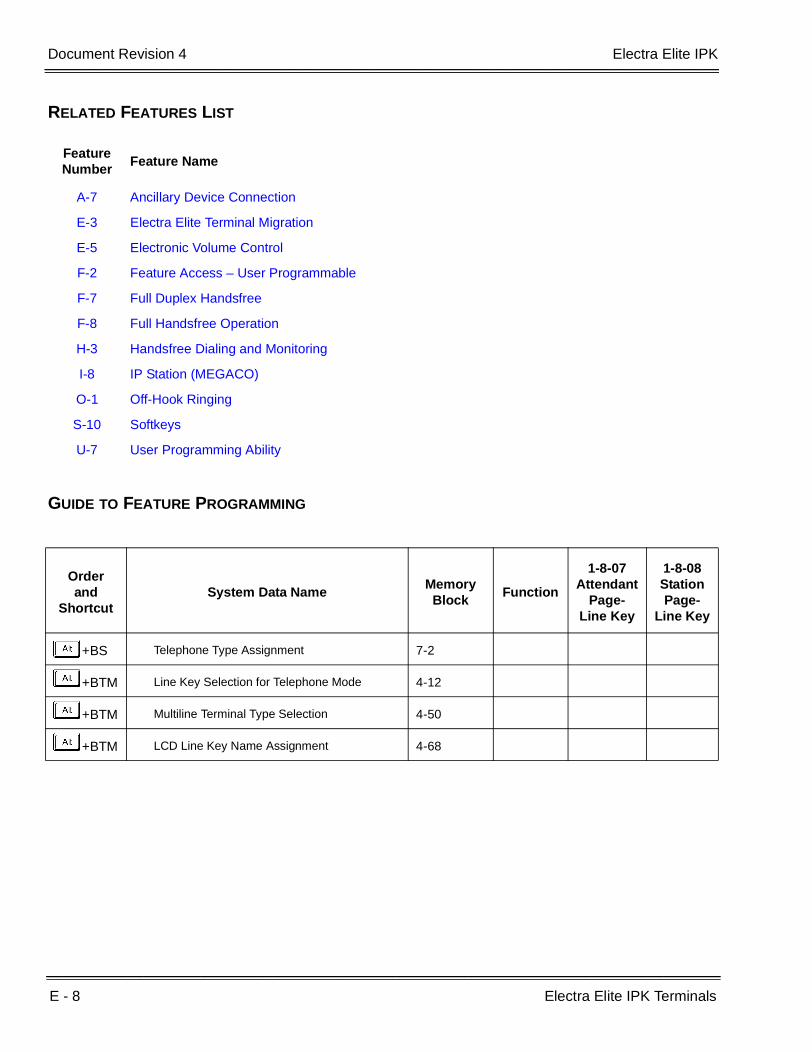
E - 8 Electra Elite IPK Terminals
___________________________________________________________________________________
___________________________________________________________________________________Document Revision 4 Electra Elite IPK
RELATED FEATURES LIST
GUIDE TO FEATURE PROGRAMMING
Feature Number
Feature Name
A-7 Ancillary Device Connection
E-3 Electra Elite Terminal Migration
E-5 Electronic Volume Control
F-2 Feature Access – User Programmable
F-7 Full Duplex Handsfree
F-8 Full Handsfree Operation
H-3 Handsfree Dialing and Monitoring
I-8 IP Station (MEGACO)
O-1 Off-Hook Ringing
S-10 Softkeys
U-7 User Programming Ability
Orderand
ShortcutSystem Data Name
Memory Block
Function
1-8-07Attendant
Page-Line Key
1-8-08StationPage-
Line Key
+BS Telephone Type Assignment 7-2
+BTM Line Key Selection for Telephone Mode 4-12
+BTM Multiline Terminal Type Selection 4-50
+BTM LCD Line Key Name Assignment 4-68

Features and Specifications Manual E - 9
___________________________________________________________________________________
___________________________________________________________________________________
Electra Elite Terminal Migration E-3
FEATURE DESCRIPTION
Electra Elite Terminal Migration allows an Electra Elite customer to protect their investment in terminals when purchasing Electra Elite IPK systems. Electra Elite Multiline Terminals can be easily used with the Electra Elite IPK systems. With very few exceptions, all terminal features and abilities that are possible on Electra Elite 48/192 are also possible with the Electra Elite IPK system.
SYSTEM AVAILABILITY
Terminal Type:
Electra Elite Multiline Terminals
Required Components:
ESI(8)-U( ) ETU
ESIB(8)-U( ) ETU
ESIE(8)-U( ) ETU
OPERATING PROCEDURES
Refer to individual feature for details.

E - 10 Electra Elite Terminal Migration
___________________________________________________________________________________
___________________________________________________________________________________Document Revision 4 Electra Elite IPK
SERVICE CONDITIONS
Restrictions
Dedicated Function Keys for Microphone, Directory, and Message are not provided with Electra Elite Multiline Terminals.
The Full Duplex handsfree feature is supported only by the Electra Elite Terminals with an HFU-U Unit installed.
Electra Professional Multiline Terminals are not supported with the Electra Elite IPK system.
RELATED FEATURES LIST
GUIDE TO FEATURE PROGRAMMING
Feature Number
Feature Name
A-7 Ancillary Device Connection
E-2 Electra Elite IPK Terminals
E-5 Electronic Volume Control
F-7 Full Duplex Handsfree
F-8 Full Handsfree Operation
H-3 Handsfree Dialing and Monitoring
O-1 Off-Hook Ringing
S-10 Softkeys
Orderand
ShortcutSystem Data Name
Memory Block
Function
1-8-07Attendant
Page-Line Key
1-8-08StationPage-
Line Key
+BS Telephone Type Assignment 7-2
+BTM Line Key Selection for Telephone Mode 4-12
+BTM Multiline Terminal Type Selection 4-50

Features and Specifications Manual E - 11
___________________________________________________________________________________
___________________________________________________________________________________
Electra Professional Terminal Migration E-4
FEATURE DESCRIPTION
Electra Professional Terminal Migration allows an Electra Elite IPK customer to protect their investment in terminals when purchasing Electra Elite IPK systems. Electra Professional Multiline Terminals can be easily used with the Electra Elite IPK systems. With very few exceptions, all terminal features and abilities that are possible on Electra Professional Level II/IIA/120 are also possible with the Electra Elite IPK system.
SYSTEM AVAILABILITY
Terminal Type:
Electra Professional Multiline Terminals
Required Software:
System software R1600 or higher is required to support Electra Professional terminals.
Required Components
None
OPERATING PROCEDURES
Not Applicable
E - 12 Electra Professional Terminal Migration
___________________________________________________________________________________
___________________________________________________________________________________Document Revision 4 Electra Elite IPK
SERVICE CONDITIONS
General:
The Electra ELite Q key is the P key on the Electra Professional terminal.
The Electra Elite T key is the N key on the Electra Professional terminal.
Restrictions:
The Off-Hook Voice Announcement feature supported by the ETW-24DS-1/2 is not provided by the Electra Elite IPK.

Features and Specifications Manual E - 13
___________________________________________________________________________________
___________________________________________________________________________________
Electronic Volume Control E-5
FEATURE DESCRIPTION
Electronic Volume Control is provided on all Multiline Terminals to allow easy changes to the LCD contrast on Multiline Display Terminals, Off-Hook Ringing volume, Station Ringing volume, and Handset/Station Speaker volume.
SYSTEM AVAILABILITY
Terminal Type:
All Multiline Terminals
Required Components:
None
OPERATING PROCEDURES
To change the LCD contrast for Multiline Display Terminals:
1. Press E to go off-hook.
2. Dial default Access Code FK.
3. Dial B from the dial pad.
4. Press UV to adjust LCD contrast (^ to increase or v to decrease).
5. Go on-hook.
- OR -
While the station is idle, press UV to adjust LCD contrast (^ to increase or v to decrease).

E - 14 Electronic Volume Control
___________________________________________________________________________________
___________________________________________________________________________________Document Revision 4 Electra Elite IPK
To change the off-hook ringing volume:
1. Go off-hook with the handset.
2. Dial default Access CodeFK.
3. Dial A from the dial pad.
4. Press UV to control off-hook ringing volume (^ to increase or v to decrease).
5. Go on-hook.
To change the station ringing volume:
Press E to go off-hook.
6. Dial default Access CodeFK.
7. Dial A from the dial pad.
8. Press UV while the station is ringing to control ringing volume (^ to increase or v to decrease).
9. Go on-hook.
To set the handset receiver volume:
1. Go off-hook with the handset.
2. Press UV to control handset receiver volume (^ to increase or v to decrease).
To set the speaker volume:
1. Press E to go off-hook.
2. Press UV to control speaker volume (^ to increase or v to decrease).
3. Go on-hook.
- OR -
While using the speakerphone, press UV to adjust the volume (^ to increase or v to decrease).

Electra Elite IPK Document Revision 4
Features and Specifications Manual E - 15
___________________________________________________________________________________
___________________________________________________________________________________
SERVICE CONDITIONS
General:
Multiline Terminal users can further increase station volume by pressing Feature + 2 during internal calls.
LCD contrast, off-hook ringing volume, station ringing volume, and speaker volume adjustments are saved in system memory.
The LCD of the Electra Elite IPK Terminals provide a volume bar indication while adjusting the following volumes or controls:
Speaker Volume
Handset/Headset Volume
BGM Volume
Ring Volume/Off Hook Ring Volume
LCD Contrast
RELATED FEATURE LIST
Feature Number
Feature Name
E-2 Electra Elite IPK Terminals
E-3 Electra Elite Terminal Migration
F-8 Full Handsfree Operation
H-3 Handsfree Dialing and Monitoring
O-1 Off-Hook Ringing

E - 16 Electronic Volume Control
___________________________________________________________________________________
___________________________________________________________________________________Document Revision 4 Electra Elite IPK
GUIDE TO FEATURE PROGRAMMING
Orderand
ShortcutSystem Data Name
Memory Block
Function
1-8-07Attendant
Page-Line Key
1-8-08StationPage-
Line Key
+BTT Access Code (1-, 2-, or 3-Digit) Assignment 1-1-46/47/
48049
+BTT Receiving Volume Selection 4-92
When the system is at default this Memory Block must be programmed for the feature to be used.

Features and Specifications Manual E - 17
___________________________________________________________________________________
___________________________________________________________________________________
E&M Tie Lines (4-Wire) E-6
FEATURE DESCRIPTION
E&M Tie Lines (4-Wire) can be connected to the system to provide communication between remote systems and facilities. The system can receive and/or transmit DTMF or DP signals on E&M Tie Lines.
SYSTEM AVAILABILITY
Terminal Type:
All Multiline Terminals
Required Components:
TLI(2)-U( ) ETU
OPERATING PROCEDURES
To originate a call:
1. Dial the Trunk Group Access Code assigned for E&M Tie Lines.
2. Dial the station to be called, or when using Uniform Numbering Network, dial the distant system number and the station to be called, or dial the Trunk Access Code and number to be called.
- OR -
1. Press the line key with direct E&M Tie Line appearance, and wait for a dial tone.
2. Dial the station to be called when using Uniform Numbering Network, dial the distant system number and the station to be called, or dial the Trunk Access Code and number to be called.

E - 18 E&M Tie Lines (4-Wire)
___________________________________________________________________________________
___________________________________________________________________________________Document Revision 4 Electra Elite IPK
SERVICE CONDITIONS
General:
Each TLI(2)-U( ) ETU supports two 4-wire E&M Tie Lines.
When a call from/to the remote end is made to a busy station in the Electra Elite IPK systems, the caller cannot set Callback Request, Step Call, or Camp-On.
The incoming ringing pattern for Tie line calls can be changed in System Programming, or voice announcement can be selected system-wide (default: 2 seconds ON/4 seconds OFF).
Immediate start, wink start, delay start, or second dial tone (default) loop supervision can be selected per trunk using System Programming.
When voice announcement for incoming Tie calls is selected, the outside party cannot switch the call to a ringing call.
The Recall key and Drop key are ignored when Tie lines are used.
Restrictions:
Use Memory Block 1-1-69 (Tie Line Code Restriction Assignment) to assign YS (outgoing Tie Line dialed digits are code Restricted) or NO (no restriction). Default is YS. With code restriction assigned, an access code must be entered in front of the dialed number in the 8-digit matching tables to dial out of a distant system.
RELATED FEATURES LIST
Feature Number
Feature Name
F-4 Flexible Numbering Plan
T-2 Tandem Switching of 4-Wire E&M Tie Lines
T-7 Trunk-to-Trunk Transfer
U-4 Uniform Numbering Network
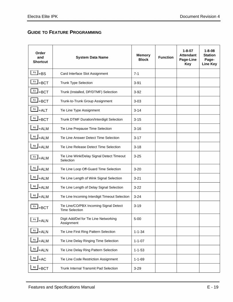
Electra Elite IPK Document Revision 4
Features and Specifications Manual E - 19
___________________________________________________________________________________
___________________________________________________________________________________
GUIDE TO FEATURE PROGRAMMING
Orderand
ShortcutSystem Data Name
Memory Block
Function
1-8-07AttendantPage-Line
Key
1-8-08StationPage-
Line Key
+BS Card Interface Slot Assignment 7-1
+BCT Trunk Type Selection 3-91
+BCT Trunk (Installed, DP/DTMF) Selection 3-92
+BCT Trunk-to-Trunk Group Assignment 3-03
+ALT Tie Line Type Assignment 3-14
+BCT Trunk DTMF Duration/Interdigit Selection 3-15
+ALM Tie Line Prepause Time Selection 3-16
+ALM Tie Line Answer Detect Time Selection 3-17
+ALM Tie Line Release Detect Time Selection 3-18
+ALMTie Line Wink/Delay Signal Detect Timeout Selection
3-25
+ALM Tie Line Loop Off-Guard Time Selection 3-20
+ALM Tie Line Length of Wink Signal Selection 3-21
+ALM Tie Line Length of Delay Signal Selection 3-22
+ALM Tie Line Incoming Interdigit Timeout Selection 3-24
+BCTTie Line/CO/PBX Incoming Signal Detect Time Selection
3-19
+ALNDigit Add/Del for Tie Line Networking Assignment
5-00
+ALN Tie Line First Ring Pattern Selection 1-1-34
+ALM Tie Line Delay Ringing Time Selection 1-1-07
+ALN Tie Line Delay Ring Pattern Selection 1-1-53
+AC Tie Line Code Restriction Assignment 1-1-69
+BCT Trunk Internal Transmit Pad Selection 3-29
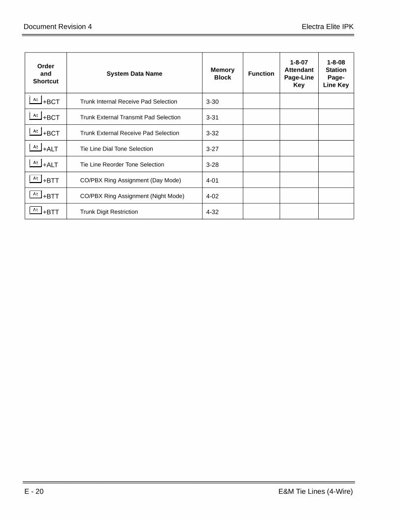
E - 20 E&M Tie Lines (4-Wire)
___________________________________________________________________________________
___________________________________________________________________________________Document Revision 4 Electra Elite IPK
+BCT Trunk Internal Receive Pad Selection 3-30
+BCT Trunk External Transmit Pad Selection 3-31
+BCT Trunk External Receive Pad Selection 3-32
+ALT Tie Line Dial Tone Selection 3-27
+ALT Tie Line Reorder Tone Selection 3-28
+BTT CO/PBX Ring Assignment (Day Mode) 4-01
+BTT CO/PBX Ring Assignment (Night Mode) 4-02
+BTT Trunk Digit Restriction 4-32
Orderand
ShortcutSystem Data Name
Memory Block
Function
1-8-07AttendantPage-Line
Key
1-8-08StationPage-
Line Key
Features and Specifications Manual E - 21
___________________________________________________________________________________
___________________________________________________________________________________
Elite ACD Plus E-7
FEATURE DESCRIPTION
Elite ACD Plus is an Automatic Call Distribution ETU that supports up to 40 agents and 12 supervisors logged on at the same time. This feature allows any incoming DIT, ANA, DID, or CO Ring Transfer call to terminate at a prearranged ACD Group of agents. The incoming call is either distributed to the agent that has been idle the longest or in accordance with a programmed preference level. Operation includes Automatic Attendant (AA), ACD only, or both AA and ACD.
The Administration Program uses a Local Area Network (LAN) that allows one administrator and up to five remote PCs, depending on site license, to monitor ACD statistics and generate reports.
An agent or supervisor can be an active member in up to four ACD Groups and can be logged on and receive calls from all four groups.
ENHANCEMENT(S)
With R4000 or higher, Elite ACD Plus 2.20 or higher is required to support the following enhanced features:
Displaying the DNIS number and name to an agent display during the ringing of an ACD call.
Recalling the display of the DNIS number and name while talking on the ACD call.
SYSTEM AVAILABILITY
Terminal Type:
Electra Elite IPK or Dterm Series i Multiline Terminals with softkeys
- OR -
Electra Elite or Dterm Series E Multiline Terminals with softkeys
Required Components:
ACD(8)-U( ) ETU
MIFM-U( ) or SPE(M)-U( ) ETU (for PC Programming during setup)

E - 22 Elite ACD Plus
___________________________________________________________________________________
___________________________________________________________________________________Document Revision 4 Electra Elite IPK
OPERATING PROCEDURES
Refer to the Elite ACD Plus Manual.
System Conditions:
The Flash ACD hardware connects to the Electra Elite through ports recognized by the KSU as Digital Voice Mail ports. Eight ACD ports are supported.
Voice Prompts and firmware are stored in Flash Memory on the Elite ACD(8)-U( ) ETU.
When a K-CCIS trunk is on hold, the Specified Line Seizure access codes can be used to retrieve the call from its held state.
The Elite ACD Plus can support and distribute incoming calls from a remote K-CCIS office. However, incoming calls into ACD Plus that result in a link reconnect are not supported. These calls must first be answered by a local station, then can be transferred into ACD Plus as long as it is not an internal (intercom) call.
CALL PROCESSING
DESCRIPTION
Abandoned Call Search
Abandoned incoming calls are not connected to agent positions. The system removes them from the queue on trunks that provide calling party disconnect supervision.
Call Distribution to Agents
Two methods can be used:
Longest IdleCalls are automatically and uniformly distributed to the agent in an ACD Group that has been idlethe longest. When incoming calls are holding, the oldest call is connected to the first availableagent.
PreferredCalls are automatically distributed among idle agents according to an assigned priority level of 1(first) to 9 (last) When agents have the same priority, the system connects the call to the longestidle agent in that priority.
When an agent or supervisor priority level is changed, the agent or supervisor must log out and then log-in for the new priority level to take effect.
Call Transfer to ACD Group Queue
CO Trunk calls that terminate to a normal station, ACD agent, or supervisor can be transferred to an ACD Group Queue.

Electra Elite IPK Document Revision 4
Features and Specifications Manual E - 23
___________________________________________________________________________________
___________________________________________________________________________________
Night Service
The administration program assigns ACD Groups to follow or ignore night mode. When an ACD Group is in night mode, the system can route incoming ACD calls to an Internal Station/Attendant or Night Announcement, or perform a Centrex Transfer.
Overflow
When all agents are busy, and calls have been held in queue for more than a specified time, overflow allows calls to be directed to an assigned station, Station Hunt Group, another ACD Plus queue, or Off-site using Centrex Transfer.
Queuing
All incoming calls for ACD Groups are placed in queue when no agent is available. A queue provides first in-first out sequence for call processing.
Pilot Numbers
A system programmed pilot number is the entry point for callers to an ACD Group. A pilot number corresponds to a Call Arrival key appearance in the Electra Elite IPK system. Each queue has an individual CAR key. Do not program an ACD Group Pilot Number in a station hunt group because Station Hunt has priority over ACD.
SERVICE CONDITIONS
General:
PC Programming (SAT) is required to assign One-Touch keys on the ports of the ACD(8)-U( ) ETU during installation and/or add or remove phones to be used by Agents.
When Memory Block 4-10 (Station Number Assignment) is used to assign any station port in the system, any ACD Plus agent logged on is logged off. The ACD Plus agents must manually log back on.
ACD Plus resets when System Refresh is performed, and all ACD Agents are logged off.
Calls are answered first in-first out.
Calls are distributed to the longest-idle agent or according to the priority level assigned to an agent.
Elite ACD Plus can be programmed per Queue to follow or ignore night mode.
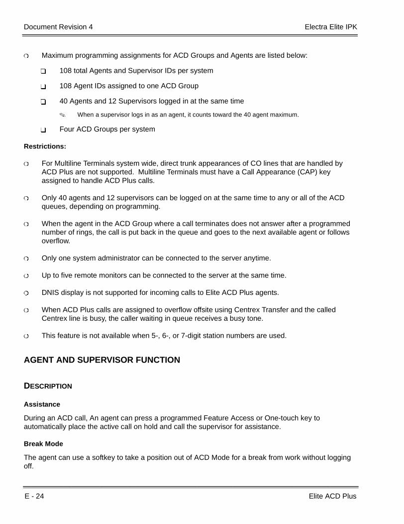
E - 24 Elite ACD Plus
___________________________________________________________________________________
___________________________________________________________________________________Document Revision 4 Electra Elite IPK
Maximum programming assignments for ACD Groups and Agents are listed below:
108 total Agents and Supervisor IDs per system
108 Agent IDs assigned to one ACD Group
40 Agents and 12 Supervisors logged in at the same time
When a supervisor logs in as an agent, it counts toward the 40 agent maximum.
Four ACD Groups per system
Restrictions:
For Multiline Terminals system wide, direct trunk appearances of CO lines that are handled by ACD Plus are not supported. Multiline Terminals must have a Call Appearance (CAP) key assigned to handle ACD Plus calls.
Only 40 agents and 12 supervisors can be logged on at the same time to any or all of the ACD queues, depending on programming.
When the agent in the ACD Group where a call terminates does not answer after a programmed number of rings, the call is put back in the queue and goes to the next available agent or follows overflow.
Only one system administrator can be connected to the server anytime.
Up to five remote monitors can be connected to the server at the same time.
DNIS display is not supported for incoming calls to Elite ACD Plus agents.
When ACD Plus calls are assigned to overflow offsite using Centrex Transfer and the called Centrex line is busy, the caller waiting in queue receives a busy tone.
This feature is not available when 5-, 6-, or 7-digit station numbers are used.
AGENT AND SUPERVISOR FUNCTION
DESCRIPTION
Assistance
During an ACD call, An agent can press a programmed Feature Access or One-touch key to automatically place the active call on hold and call the supervisor for assistance.
Break Mode
The agent can use a softkey to take a position out of ACD Mode for a break from work without logging off.
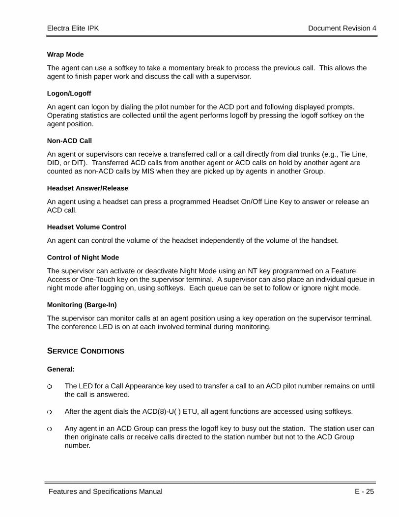
Electra Elite IPK Document Revision 4
Features and Specifications Manual E - 25
___________________________________________________________________________________
___________________________________________________________________________________
Wrap Mode
The agent can use a softkey to take a momentary break to process the previous call. This allows the agent to finish paper work and discuss the call with a supervisor.
Logon/Logoff
An agent can logon by dialing the pilot number for the ACD port and following displayed prompts. Operating statistics are collected until the agent performs logoff by pressing the logoff softkey on the agent position.
Non-ACD Call
An agent or supervisors can receive a transferred call or a call directly from dial trunks (e.g., Tie Line, DID, or DIT). Transferred ACD calls from another agent or ACD calls on hold by another agent are counted as non-ACD calls by MIS when they are picked up by agents in another Group.
Headset Answer/Release
An agent using a headset can press a programmed Headset On/Off Line Key to answer or release an ACD call.
Headset Volume Control
An agent can control the volume of the headset independently of the volume of the handset.
Control of Night Mode
The supervisor can activate or deactivate Night Mode using an NT key programmed on a Feature Access or One-Touch key on the supervisor terminal. A supervisor can also place an individual queue in night mode after logging on, using softkeys. Each queue can be set to follow or ignore night mode.
Monitoring (Barge-In)
The supervisor can monitor calls at an agent position using a key operation on the supervisor terminal. The conference LED is on at each involved terminal during monitoring.
SERVICE CONDITIONS
General:
The LED for a Call Appearance key used to transfer a call to an ACD pilot number remains on until the call is answered.
After the agent dials the ACD(8)-U( ) ETU, all agent functions are accessed using softkeys.
Any agent in an ACD Group can press the logoff key to busy out the station. The station user can then originate calls or receive calls directed to the station number but not to the ACD Group number.

E - 26 Elite ACD Plus
___________________________________________________________________________________
___________________________________________________________________________________Document Revision 4 Electra Elite IPK
A default alert tone is provided for Barge-In Monitoring. The tone can be disabled in system programming.
Restrictions:
An agent can logoff or enter Break or Wrap mode only when the station is idle. The agent can request these conditions by pressing the applicable softkey during an ACD call. The last entered request is carried out when the telephone returns to idle.
An agent cannot receive another ACD call while an existing ACD call is on hold. After the held call is terminated, the agent can then receive ACD calls.
Agents and supervisors must have a DTU/DTP or DTH/DTR terminal with softkeys.
When an ACD Plus agent sets Call Forwarding, incoming calls, including ACD Plus calls, follow the Call Forward setting. To prevent ACD Plus calls from forwarding, Memory Block 1-2-22 (Call Forward – No Answer Time Selection) should be set at least five seconds longer than the Time Agent Rings Without Answer timer. When an agent sets Call Forward – All Call, the agent is viewed as busy and does not receive ACD Plus calls.
Incoming ACD calls cannot be received during Break or Wrap Mode.
AUTOMATED ATTENDANT FUNCTION
SERVICE CONDITIONS
General:
For Centrex lines, the AA can transfer a call to any valid Centrex number using Centrex service. After the call is transferred at the Central Office, it does not use any Electra Elite IPK trunk lines.
Additional hardware is not required to support Automated Attendant.
The answering time after the incoming CO/PBX call rings can be programmed per trunk when using Automated Attendant.
Restrictions:
Supervisors can record AA and ACD queue messages again using the telephone. The maximum message lasts 90 seconds.
Automated Attendant (AA) allows a caller to direct dial a valid extension defined by the Administration application or one-key dialing only while a message is playing, when direct dial is enabled.

Electra Elite IPK Document Revision 4
Features and Specifications Manual E - 27
___________________________________________________________________________________
___________________________________________________________________________________
When caller does not select an Automated Attendant transfer option after the AA message finishes playing, the caller is automatically transferred to the default transfer number. When a default transfer number is not assigned, the AA message replays.
Elite ACD Plus can be programmed to answer lines with AA while sending others directly to the ACD queue.
The DIT assignment bypasses the Automatic Attendant function for any trunk.
ANNOUNCEMENTS FUNCTION
DESCRIPTION
By default, all announcements except the AA and On-Hold message are recorded. Using the Administration program, most messages can be allowed or denied per group. Both AA messages and the Numbers in Queue messages are shared by all groups. The supervisor can logon by telephone to ACD and change any message when granted access rights for the group. Recordings can also be changed using the Administration program by uploading a voice file in the correct format from the PC.
All prompts must be recorded or converted to 8KHz OKI ADPCM format.
The numbers prompt must be in BICOM Indexed Play File Format with silence compression in addition to the requirement listed above.
Automated Attendant Messages
A standard greeting that is not recorded at default and an error message that plays when an invalid selection is dialed are included. Both messages are shared by all groups.
ACD Greeting Message
A caller hears the message that is recorded per group when agents are not available to answer a call. The Administration program can set this message to play first even when available agents are idle.
Numbers in Queue Messages
These messages are shared by all groups, can be recorded by the Supervisor using a telephone, and contain the numbers played for queue depth. During recording by telephone, the number to speak is shown in the display. When a voice file from a PC is used, the message must be in indexed play format or the queue depth feature does not work.
ACD On-Hold Message
This message (recorded and enabled per group) plays after the ACD Greeting and Refresh 1 and Refresh 2 messages. By default this message is not recorded.
ACD Refresh Message 1
This message (recorded and enabled per group) plays at programmed intervals for callers that remain in queue. It plays after the ACD Greeting and before ACD Refresh Message 2.

E - 28 Elite ACD Plus
___________________________________________________________________________________
___________________________________________________________________________________Document Revision 4 Electra Elite IPK
ACD Refresh Message 2
This message (recorded and enabled per group) plays at programmed intervals for callers that remain in queue. It plays after ACD Refresh Message 1, and/or On-Hold messages.
Night Message
This message (recorded and enabled per group) is played when a group is in night mode and the message is enabled for that queue.
ACD Queue Status Header
This message (recorded and enabled per group) is used with the queue depth feature to indicate the place in the queue. By default it states: “you are caller number” followed by the prompt that plays the correct place for the caller. This message plays after the ACD Greeting, ACD Refresh 1 and ACD Refresh 2 messages.
ACD Queue Status Trailer
A message (in queue) that is recorded and enabled per group is played after the Queue status header and Numbers Message.
SERVICE CONDITIONS
General:
When all agents in the ACD group where a call is terminated are busy, the call waits in queue until an agent is available. The caller receives announcements, queue depth indication or Music on Hold.
Each caller hears every announcement from the beginning.
When an agent becomes available, the caller is immediately connected even when an announcement is in progress.
Restrictions:
The maximum time for any message is 90 seconds.
DIT/ANA, CO Ring transfers, AA transfers, or DID/Tie Line calls must be directed to an ACD pilot number to receive announcements.
When all ACD ports are busy, the incoming caller continues to hear ringback tone or Music on Hold until an ACD port is available.
Only seven calls can be connected to the ACD(8)-U( ) ETU and receive announcements at the same time. Port 1 is reserved for agents to logon during heavy traffic. A maximum of 64 trunks can be supported.

Electra Elite IPK Document Revision 4
Features and Specifications Manual E - 29
___________________________________________________________________________________
___________________________________________________________________________________
REAL TIME DISPLAY (RTD)
DESCRIPTION
The Real Time Display (RTD) consists of a server application that is installed on the same PC running the ACD Plus server software, and client software that is installed on agent PCs. This application provides real time queue and agent information to the individual desktop as a cost effective alternative to expensive wall displays that display queue status information. In addition to the queue and agent status information, the application also allows text messaging to be sent to individual agents and groups of agents.
Elite ACD Plus Software Suite V 2.0.2 or higher is required to support the RTD feature.
A sample display of the RTD is shown below.
SERVICE CONDITIONS
General:
An optional RTD License Key is available to support additional RTD clients:
Without an RTD License Key, up to three RTD clients are supported.
With an RTD License Key, up to 100 RTD clients are supported.
For each queue, the RTD lists the following statistics:
Number of agents logged into the queue
Number of calls waiting in the queue
Wait time of the call that has been in the queue the longest
By default, the top line on the Real Time Display shows the headers for each statistic column. The bottom row of the Real Time Display shows text messages as they are received from other users.

E - 30 Elite ACD Plus
___________________________________________________________________________________
___________________________________________________________________________________Document Revision 4 Electra Elite IPK
The following appearances of the RTD can be customized:
Turning headers off/on
Resizing
Repositioning
Keeping the RTD image visible
The Real Time Display application allows text messages to be sent between RTD clients. This ability can be used to send general announcements to groups of users or direct comments to individual agents. All RTD clients can receive text messages; however, the ability to send text messages is controlled through settings in the ACD Plus server.
When an RTD client receives a text message, the message is scrolled across the bottom line of the display. The message continues to scroll until the message duration has expired or the user selects the Clear function. When multiple messages are received, they are displayed sequentially in the order in which they were received.
A threshold can be defined on the ACD Plus server for each statistic shown on the Real Time Display. The threshold represents a critical level that indicates the efficiency of call center operations. Threshold levels are shown on the RTD by changing the color of the individual statistic when the threshold is reached. A green level indicates that field is within an acceptable range. A yellow level is a warning level for that field. A critical threshold is indicated by a red level.
The RTD can also provide additional alerts (a Tone or a Popup) as threshold levels are reached.
Restrictions:
The PC requirements for Elite ACD Plus Software Suite V 2.0.2 or higher running the RTD feature are as follows:
Software Requirements
Microsoft Windows 98, 2000, Me, or XP
Hardware Requirements
IBM-compatible machine with at least a 500Mhz CPU
ACD Plus and RTD Server -- 256MB RAM
RTD Client -- 128MB RAM
Minimum 40 MB of available hard disk space
CD-ROM drive
Unused Serial port or LAN to connect to the ACD Plus ETU
Unused Parallel/USB port to connect to the Client key
Mouse
Printer (optional)

Electra Elite IPK Document Revision 4
Features and Specifications Manual E - 31
___________________________________________________________________________________
___________________________________________________________________________________
Related Feature List
GUIDE TO FEATURE PROGRAMMING
Feature Number
Feature Name
S-10 Softkeys
Orderand
ShortcutSystem Data Name
Memory Block
Function
1-8-07AttendantPage-Line
Key
1-8-08StationPage-
Line Key
+BS Card Interface Slot Assignment 7-1
+BS Telephone Type Assignment 7-2
+BK Call Arrival Key Block Assignment 1-2-04
+BA Access Code (1-, 2-, 3-Digit) Assignment 1-1-46~48 042, 064
+BM Call Forward - No Answer Time Selection 1-2-22
+BTS Class of Service (Station) Feature Selection 2 1-8-08 3-8
+BCT DIT Assignment 3-42
+BCT ANA Assignment 3-43
+BTT CO/PBX Ring Assignment (Day Mode) 4-01
+BTT CO/PBX Ring Assignment (Night Mode) 4-02
+BS Station Number Assignment 4-10
+BTM Line Key Selection for Telephone Mode 4-12
+BTT Intercom Master Hunt Number Selection 4-14
+BTT Intercom Master Hunt Number Forward
Assignment4-15
+BTT Station to Class of Service Feature
Assignment4-17
+BTMExtension Line Key Ring Assignment (Day Mode)
4-37
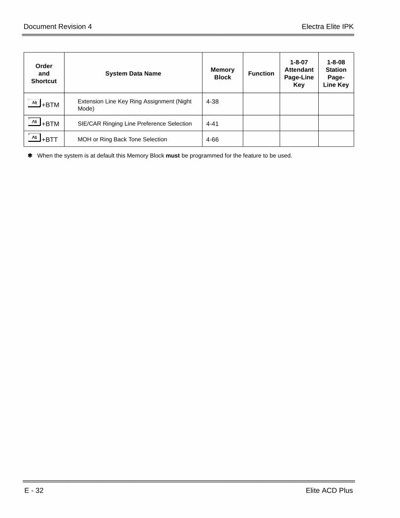
E - 32 Elite ACD Plus
___________________________________________________________________________________
___________________________________________________________________________________Document Revision 4 Electra Elite IPK
+BTMExtension Line Key Ring Assignment (Night Mode)
4-38
+BTM SIE/CAR Ringing Line Preference Selection 4-41
+BTT MOH or Ring Back Tone Selection 4-66
When the system is at default this Memory Block must be programmed for the feature to be used.
Orderand
ShortcutSystem Data Name
Memory Block
Function
1-8-07AttendantPage-Line
Key
1-8-08StationPage-
Line Key

Features and Specifications Manual E - 33
___________________________________________________________________________________
___________________________________________________________________________________
Elite CallAnalyst E-8
FEATURE DESCRIPTION
Elite CallAnalyst is an easy to use, graphically oriented software package that allows you to monitor and analyze telephone calls, understand telephone usage, and cut costs. Incoming and outgoing calls are tracked accurately along with the date and time of the call. When the incoming telephone call must be tracked with name and/or telephone numbers, Elite CallAnalyst requires Caller ID service from the local telephone company.
Elite CallAnalyst increases productivity, facilitates billing, and helps detect toll fraud and telephone abuse. It also has powerful tabular (text) and graphic report generating ability. Reports include extension/line summaries, date, time, and department summaries, longest/most expensive calls, and most frequently called numbers. These reports can be used to analyze your telephone as a critical business communication tool, improve its business effectiveness, and reduce your telephone costs. A report can be generated showing calling patterns by volume or duration on a color-coded United States map. This can help a Customer Support, Sales Order, or Telemarketing business become more focused, more productive, and more cost effective.
Highlights of Elite CallAnalyst and Elite CallAnalyst Lite:
Network based
Fraud monitoring
Automatic report and data archival scheduling
Real-time inbound/outbound call monitoring
Call costing and user configurable rate plans
Time billing
Variety of customer configurable report categories:
Date/Time and area code
Filter reports based on date, time, extension, line, duration, account code, forced account code, name, and number
Customized reports
E - 34 Elite CallAnalyst
___________________________________________________________________________________
___________________________________________________________________________________Document Revision 4 Electra Elite IPK
SYSTEM AVAILABILITY
Terminal Type:
All Terminals
Incoming CO/PBX Call
Outgoing CO/PBX Call
Conference CO/PBX Call
Transferred CO/PBX Call
Required Components:
MIFM-U( ) ETU
SPE(M)-U( ) ETU
Minimum PC Requirements:
PC with Pentium Processor
64 Mb Ram
VGA monitor 800 X 600 res. (SVGA 1024 X 768 recommended)
Windows 95/98 Me, NT-SP 3 or later, 2000
80 Mb free hard drive space
CD-ROM drive (When using CD for installation)
Available serial port and RS-232 cable
Printer for reports
The Elite CallAnalyst software should be installed on a separate PC, but other applications may be installed. Performance depends on the need for memory and processing for the other applications.
OPERATING PROCEDURES
None

Electra Elite IPK Document Revision 4
Features and Specifications Manual E - 35
___________________________________________________________________________________
___________________________________________________________________________________
SERVICE CONDITIONS
General:
The following software items are installed on the PC:
Call Data Manager (CDM) to collect call records from the system.
Elite CallAnalyst and Elite CallAnalyst Lite (version depends on license purchased) to allow reports and other analyst features.
Scheduler (default installed) to allow reports and database archival depending on the Elite CallAnalyst version.
Elite CallAnalyst Manual (default installed, PDF format).
The following optional modules of Elite CallAnalyst Software require license upgrade:
Network Client
Network clients must then call NEC for additional licensing. The license is issued on theCallAnalyst Server installation. All license information is maintained on the server PC.Because the license is unique to the PC where the server is installed, you must follow thehelp files in the license screen to move the license to another location.
Fraud alert
This protects against telephone abuse. (No additional license is required.)
Refer to the Elite CallAnalyst Manual installed with the software for more detailed information.
When the printer or other I/O device fails to operate, approximately 100 call records are saved in the MIFM-U10 ETU or approximately 200 call records are saved in the MIFM-U20 or SPE(M)-U( ) ETU. When the buffer is full, the earliest call record is lost when the next call record is stored.
Call record data provides Start Time, Trunk Number, Trunk Group, Call Type, Station Number, Duration, Number Dialed, LCR, Calling Station number, and Transferred Station Number.
A maximum of 24 digits is allowed for output of a telephone number.
When the printer is assigned, but a printer is not connected to the system, PRINTER TROUBLE is displayed on the LCD and an audible alert tone is provided at the first two Multiline Terminals (Stations 100 and 101) connected to the system.
When the MIFM-U( ) ETU or SPE(M)-U( ) ETU is not installed or disabled an alarm indication is not provided.
Restrictions:
Call records are not provided for internal calls.

E - 36 Elite CallAnalyst
___________________________________________________________________________________
___________________________________________________________________________________Document Revision 4 Electra Elite IPK
Caller ID name is not printed on SMDR.
DNIS digits are not printed with SMDR Records.
When 5-, 6-, or 7-digit station numbers are used, only the last four digits of the extension number are printed (provided) by SMDR.
GUIDE TO FEATURE PROGRAMMING
Orderand
ShortcutSystem Data Name
Memory Block
Function
1-8-07Attendant
Page-Line Key
1-8-08StationPage-
Line Key
+AS SMDR Print Format 1-5-02
+AS Printer Connect Selection 1-5-13
+AS Printer Line Feed Control Selection 1-5-14
+AS SMDR Valid Call Time Assignment 1-5-25
+AS SMDR Telephone Print Selection 1-5-26
+AS SMDR Telephone Print Selection 4-56
+BS Card Interface Slot Assignment 7-1
+BS MIF (LCR) Assignment 7-3-01
+BS MIF (SMDR ) Assignment 7-3-02

Features and Specifications Manual E - 37
___________________________________________________________________________________
___________________________________________________________________________________
Elite CallAnalyst Enterprise Server E-9
FEATURE DESCRIPTION
The Elite CallAnalyst Enterprise Server is a Call Accounting and Telemanagement solution suitable for installations with large call volumes or multiple locations/switches requiring consolidation of call data (SMDR/CDR) and centralized reporting. It is an easy to use, graphically oriented software solution that allows the user to monitor and analyze telephone calls, understand telephone usage, and cut costs. Each server accurately tracks both incoming and outgoing calls along with the date and time. When tracking incoming calls using telephone numbers, Caller ID services are required from the local telephone company.
The Elite CallAnalyst Enterprise Server increases productivity, facilitates billing, and helps to identify toll fraud and telephone abuse. It also has powerful tabular text and graphic report generating abilities. Reports include extension/line summaries, date/time and department summaries, longest and most expensive calls, most frequently called numbers, and other commonly used summaries. These reports help the user to analyze the telephone as a critical business communication tool to improve business effectiveness. For example, a report can be generated showing call patterns by volume or duration on a color-coded map of the U.S. that can be used to help Customer Support, Sales Order, or Telemarketing business become more focused, more productive, and cost effective.
The following Elite CallAnalyst Enterprise Server features are provided:
Centralized data administration from multiple call data sources
Consolidation of call data from remote locations/switches
Collection of call data over a TCP/IP Network
Customized reports
Automatic scheduling of reports and data archival
Fraud monitoring
Call costing and rate tables
Real-time inbound/outbound call monitoring
Data analysis from multiple locations
For detailed information, refer to the Elite CallAnalyst Enterprise Server manual provided with the software.

E - 38 Elite CallAnalyst Enterprise Server
___________________________________________________________________________________
___________________________________________________________________________________Document Revision 4 Electra Elite IPK
SYSTEM AVAILABILITY
Software:
Elite CallAnalyst Enterprise Server
CallAnalyst Network Client (optional)
CallAlert! (optional)
Microsoft SQL Server 2000
- OR -
Microsoft Database Engine (MSDE)
Required Components:
MIFM-U( ) ETU
- OR -
SPE(M)-U( ) ETU
OPERATING PROCEDURES
None
SERVICE CONDITIONS
General:
The Elite CallAnalyst Enterprise Server installation CD includes:
Elite CallAnalyst Enterprise Server (CES)
Elite CallAnalyst Enterprise Server
Elite CallAnalyst Enterprise Server - Network Client
Elite CallAnalyst Enterprise Server - CallAlert
MSR Thin Client
Microsoft Database Engine (MSDE) installer
Internet Explorer 6.0 (IE)
Adobe Acrobat reader 5.0

Electra Elite IPK Document Revision 4
Features and Specifications Manual E - 39
___________________________________________________________________________________
___________________________________________________________________________________
Related items of the Elite CallAnalyst Enterprise Server are described in the table below:
Different installation configurations available for the Elite CallAnalyst Enterprise Server and the requirements for each are described in the table below:
Product Description
Elite CallAnalyst Enterprise Server (CES)
Includes:
Server Software with MSDE installer
(1) Site License for SMDR
Support for 120 Stations
Support for 64 Trunks
Requires Activation Code
Additional Site License
Required for each additional remote site connected to Server site. A license file that allows the total number of sites to be monitored is also required.
Additional Network Client License (Activation Code)
Required for each additional Network Client that accesses the CES Server for reports.An Activation Code is required.The Site Key/License issued on the server allows the required number of Network Clients to have concurrent access to the server for reporting.
Multi-Site Reporter Thin Client
Required to be installed on a PC at remote locations to collect serial data locally and forward it to the central CES hub over TCP/IP Network.
Type of Installation PC Requirements Notes
Single Site, Single PC
Single PC with the following installed:
MSDE or SQL Server 2000(Database server)
CES
CallAlert! Installed (optional)
CallAlert! should be installed only if telephone abuse/fraud or call patterns need to be detected to generate an alarm.

E - 40 Elite CallAnalyst Enterprise Server
___________________________________________________________________________________
___________________________________________________________________________________Document Revision 4 Electra Elite IPK
Single Site, Multiple Network Clients accessing Server for reports
Server PC with the following installed:
MSDE or SQL Server 2000(Database server)
CES
CallAlert! Installed (optional)
Client PC(s) with the following installed:
CallAnalyst Client
CallAlert! Installed (optional)
When MSDE is used for the Database, only five Network Clients are allowed.
Multi-Site monitoring with Single PC Installation
Main Site with Single PC and the following installed:
MSDE or SQL Server 2000(Database server)
CES
CallAlert! Installed (optional)
Remote Sites with SPE or PC running Thin Client connected to the Main Site over a TCP/IP Network
MSR Thin Client installed on a local PC converts SMDR serial data to Ethernet data packets.
Multi-Site Installation with Multiple Network Clients accessing Server for reports
Server PC with the following installed:
MSDE or SQL Server 2000(Database server)
CES
CallAlert! Installed (optional)
Client PC(s) with the following installed:
CallAnalyst Client
CallAlert! Installed (optional)
Remote Sites with SPE or PC running Thin Client
When MSDE is used for the Database, only five Network Clients are allowed.
MSR Thin Client installed on a local PC converts SMDR serial data to Ethernet data packets.
Type of Installation PC Requirements Notes

Electra Elite IPK Document Revision 4
Features and Specifications Manual E - 41
___________________________________________________________________________________
___________________________________________________________________________________
PC/Server with the following installed: • SQL 2000 or MSDE • CES • Call Alert Installed (optional).
Serial Cable
Example of Single PC/Server Installation with Direct Serial to PC Com Port (RS-232)
Serial Cable
LAN / WAN
PC/Server with the following installed: • SQL 2000 or MSDE • CES • Call Alert Installed
PC with the following installed: • CallAnalyst Client • Call Alert Installed Note: If MSDE is used for the Database only 5 Network Clients are allowed.
Example of Single Site/Single Network Client Installation with Direct Serial to PC Com Port (RS-232)

E - 42 Elite CallAnalyst Enterprise Server
___________________________________________________________________________________
___________________________________________________________________________________Document Revision 4 Electra Elite IPK
LAN / WAN
Serial Cable
Server with MSDE or SQL 2000
Site 1 Site 2
CallAnalyst Clients
Example of Multi Site Installation with Multiple PC/Server Installation with a Direct Serial to PC Com Port (RS-232) and a Direct Ethernet to PC connection.
Ethernet from SPE
Elite LAN PCProgramming Device
PC withThin Client
Serial Cable
LAN
LAN / WAN
Serial Serial
Server with MSDE or SQL 2000
Site 1 Site 2
PC with Thin Client
Elite LAN PC Programming Device
CallAnalyst Clients
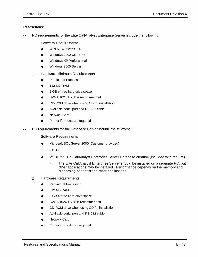
Electra Elite IPK Document Revision 4
Features and Specifications Manual E - 43
___________________________________________________________________________________
___________________________________________________________________________________
Restrictions:
PC requirements for the Elite CallAnalyst Enterprise Server include the following:
Software Requirements
WIN NT 4.0 with SP 6
Windows 2000 with SP 3
Windows XP Professional
Windows 2000 Server
Hardware Minimum Requirements
Pentium III Processor
512 MB RAM
2 GB of free hard drive space
SVGA 1024 X 768 is recommended
CD-ROM drive when using CD for installation
Available serial port and RS-232 cable
Network Card
Printer if reports are required
PC requirements for the Database Server include the following:
Software Requirements
Microsoft SQL Server 2000 (Customer provided)
- OR -
MSDE for Elite CallAnalyst Enterprise Server Database creation (included with feature)
The Elite CallAnalyst Enterprise Server should be installed on a separate PC, but other applications may be installed. Performance depends on the memory and processing needs for the other applications.
Hardware Requirements
Pentium III Processor
512 MB RAM
2 GB of free hard drive space
SVGA 1024 X 768 is recommended
CD-ROM drive when using CD for installation
Available serial port and RS-232 cable.
Network Card
Printer if reports are required

E - 44 Elite CallAnalyst Enterprise Server
___________________________________________________________________________________
___________________________________________________________________________________Document Revision 4 Electra Elite IPK
PC requirements for CallAnalyst Clients and/or CallAlert! include the following:
Software Requirements
WIN NT 4.0 with SP 6
Windows 2000 with SP 3
Windows XP Professional
Internet Explore 5.0 or higher
Hardware Requirements
Pentium III Processor
256 MB RAM
1 GB of free hard drive space
Network Card
Requirements for Database Server Types includes:
Microsoft SQL Server 2000 (Customer provided)
Pentium III Processor
MSDE restrictions include:
Maximum recommended size: 1 GB
Maximum Network Clients: 5

Features and Specifications Manual E - 45
___________________________________________________________________________________
___________________________________________________________________________________
EliteApps - Interactive Voice Response E-10
FEATURE DESCRIPTION
Interactive Voice Response (IVR) is a software application that accepts a combination of voice telephone input, database information, and telephone keypad selection to provide audio (usually voice) information to callers and databases, place calls, transfer calls, and send e-mail messages. IVRs also allow callers to provide voice and data information to be stored in databases used by other user applications. Common IVR applications include:
Bank and stock account balances and transfers
Surveys and polls
Call center hold and forwarding
Order entry tracking
Simple order entry transactions
Selective information lookup (movie schedules, etc.)
The IVR application uses pre-recorded voice, optional text-to-speech, call flow logic, access to relevant data, and records voice input for later handling. Using computer telephony integration (CTI), the IVR can hand off a call to someone that can view data related to the caller at a display.
The programmable IVR uses open database connectivity (ODBC) connections to databases to allow complete customizing of call flows and information anytime. The IVR can generate e-mail messages and can be remotely monitored and configured using a LAN or WAN in a totally secure environment.
Basically, the IVR receives calls, collects information, and forwards the call.
A customer can use NEC Professional Services to customize the IVR to meet a unique user application.
The following major functions are provided:
Call control
Answer an inbound call.
Place an outbound call.
Collect DTMF digits from a caller.

E - 46 EliteApps - Interactive Voice Response
___________________________________________________________________________________
___________________________________________________________________________________Document Revision 4 Electra Elite IPK
Play one or more audio files to a caller.
Play text to a caller as digits, number, date, time, or money.
Record from a caller into a file.
Select a menu item.
Access caller ID information.
Set all call control parameters.
Supervise normal and Blind transfers.
Announce a call prior to connection to another port.
Multilingual support
Database Access (ODBC)
Open a Data Source Name (DSN).
Close an opened DSN.
Execute a direct SQL statement to query, insert, update, and delete records.
Get data fields from a selected record.
Get the next selected record.
Use database information to control program logic or present data to callers.
Program Control
Script driven for total control
if, else, else if, end if logic control with up to 20 levels of nesting
goto for branching to a label
exec to start a whole new program
run and return to execute a function (with nesting) and continue
User embedding of comments and tracing information
User generation of events

Electra Elite IPK Document Revision 4
Features and Specifications Manual E - 47
___________________________________________________________________________________
___________________________________________________________________________________
Logging
Unlimited number of user definable logs.
User specified information in logs.
Date and time stamping of all log entries.
Caching
Audio files are automatically cached in Zeus cache.
Memory is available for caching that can be configured.
No user actions are required.
Modified audio files are automatically updated in cache.
Timers
Pause for configured number of milliseconds.
Mark the current date and time.
Get the number of seconds from a marked time now.
Assign a new script to be executed after user specified number of seconds.
Suspend a timer.
Cancel a timer.
Variables
Variables are user definable.
Variables can be integer or string type.
Set a variable to the result of an expression.
Set a variable to a string.
Set a variable to another variable.
Set a variable to the results of a function( ).
Use variables anywhere in script syntax.
Strings
String extraction: Left, Mid, Right
String replacement

E - 48 EliteApps - Interactive Voice Response
___________________________________________________________________________________
___________________________________________________________________________________Document Revision 4 Electra Elite IPK
System information: current day of month, day of week, year, month, hour, minute, date
Temporary unique name generation
File Control
Rename files
Remove files
Copy files
Test the existence of a file or directory.
SYSTEM AVAILABILITY
Terminal Type:
All Stations
Required Components:
IVR(8)-U( ) ETU
OPERATING PROCEDURES
Operating Procedures depend on the application.
SERVICE CONDITIONS
General:
The IVR(8)-U( ) ETU is assigned as VMS 8 in Memory Block 7-1 (Card Interface Slot Assignment), and Digital VM is assigned in Memory Block 7-2 (Telephone Type Assignment).
RELATED FEATURE LIST
Feature Number
Feature Name
D-8 Digital Voice Mail
E-7 Elite ACD Plus

Electra Elite IPK Document Revision 4
Features and Specifications Manual E - 49
___________________________________________________________________________________
___________________________________________________________________________________
GUIDE TO FEATURE PROGRAMMING
Orderand
ShortcutSystem Data Name
Memory Block
Function
1-8-07Attendant
Page-Line Key
1-8-08StationPage-
Line Key
+BTS Card Interface Slot Assignment 7-1 4-3, 4-4
+BS Telephone Type Assignment 7-2
+BS Station Number Assignment 4-10
+BTT Intercom Master Hunt Number Selection 4-14
+BTTIntercom Master Hunt Number Forward Assignment
4-15
When the system is at default this Memory Block must be programmed for the feature to be used.

E - 50 EliteApps - Interactive Voice Response
___________________________________________________________________________________
___________________________________________________________________________________Document Revision 4 Electra Elite IPK
THIS PAGE INTENTIONALLY LEFT BLANK
Features and Specifications Manual E - 51
___________________________________________________________________________________
___________________________________________________________________________________
EliteApps - PC Attendant E-11
FEATURE DESCRIPTION
The EliteApps - PC Attendant provides easy access to the most common functions required by an operator or receptionist. Using this application, the attendant can easily manage call handling tasks without having to switch attention between the telephone and the PC. Additional features, such as a company directory, recording ability, and PC-to-PC messaging, provide additional value to the NEC attendant position. The EliteApps - PC Attendant has three main components:
1. EliteApps - PC Attendant Application Software
This application runs on a PC and provides the PC based GUI (Graphical User Interface) and features.
2. CTU Adapter
The adapter is installed on the Multiline Terminal and interfaces the Electra Elite IPK KSU with the USB (Universal Serial Bus) port on the PC.
3. Headset (optional)
A headset can be plugged into the Multiline Terminal and used when making or receiving calls with the EliteApps - PC Attendant.
The EliteApps - PC Attendant runs on the PC and communicates with the Electra Elite IPK through a normal digital station port using the CTU Adapter that is attached to the telephone. When a call comes into this station, the PC Attendant displays it on the PC and provides several features that allow the user to handle the call quickly. EliteApps - PC Attendant can be minimized to run in the background and pop to the front when call activity occurs. Calls can then be handled using either the keyboard or the mouse. The attendant speaks to the caller through the telephone handset, headset, or speakerphone.
The following major features are described below:
Company Directory
Entire company directory or selected records can be printed.
Call Log
The Call log can be archived to a separate file and accessed by other applications such as Microsoft Excel.

E - 52 EliteApps - PC Attendant
___________________________________________________________________________________
___________________________________________________________________________________Document Revision 4 Electra Elite IPK
Direct Station Select/Busy Lamp Field
The PC Attendant can display up to 120 BLF keys, when used with a compatible Voicemail or ACD Plus ETU.
Recording
The PC Attendant can be configured to automatically record all calls handled by the attendant.
Quick Message
Quick Message allows the attendant to send a message to another employee PC. The message automatically pops up on the recipient screen and allows a response to be sent back to the attendant. This is Ideal for message notification when an employee is on the phone.
SYSTEM AVAILABILITY
Terminal Type:
When Extended DSS/BLFs ARE NOT required:
Any DTH/DTR Terminal with a CT(U)-R Unit installed
- OR -
Any DTU/DTP Terminal with a CTU(S)-U Unit installed
When Extended DSS/BLFs ARE required:
DTH/DTR-8-1 Terminal with a CT(U)-R Unit installed
- OR -
DTU/DTP-8-1 Terminal with a CTU(S)-U Unit installed
Required Components:
CT(U)-R Unit for DTH/DTR type Multiline Terminal
AC-R Unit for CT(U)-R Unit
- OR -
CTU(S)-U Unit for DTU/DTP type Multiline Terminal
ACA-U UNIT for CTU(S)-U Unit
CMS/FMS/VMS( )-U20/30 ETU or higher
- OR -
ACD(8)-U( ) ETU when 96 Extended DSS/BLFs are required.

Electra Elite IPK Document Revision 4
Features and Specifications Manual E - 53
___________________________________________________________________________________
___________________________________________________________________________________
System Administration Terminal (SAT) software and MIFM-U( ) or SPE(M)-U( ) ETU (for PC Programming during setup)
PC requirements for EliteApps - PC Attendant
Software Requirements
Windows 98 SE, Windows 2000, Windows ME, or Windows XP
Hardware Requirements
Intel Pentium III, Celeron or higher compatible processor with a minimum speed of 500MHz
256MB RAM (minimum)
A minimum of 15 MB of free hard disk space for installation. Additional hard disk space is required for calls to be recorded.
CD-ROM drive
Mouse
Unused USB port to connect to the Client key
Optional PC speakers and microphone
Printer is required when using the printing features of the PC Attendant.
MAPI compliant e-mail application is required when using the e-mail features of PC Attendant.
OPERATING PROCEDURES
This depends on the application.
SERVICE CONDITIONS
General:
Multiple user profiles can be defined on a single PC. This allows different individuals to use the attendant workstation and maintain their own configuration settings.
A list of the parked call locations provides the attendant with a reminder of the last call that application parked at each location. The attendant can click on the Parked Call list to retrieve a call from a parked call location.
The PC Attendant can monitor the same BLFs that are defined for ACD Plus, as long as they are within the first 96 One Touch keys on the ETU. The application for the PC Attendant sends the state information for the first 96 keys to the PC. Within the PC Attendant configuration, you specify which of these 96 keys are to be interpreted as console BLF keys. So you do not have to define two BLF keys to have the PC Attendant monitor an agent telephone.

E - 54 EliteApps - PC Attendant
___________________________________________________________________________________
___________________________________________________________________________________Document Revision 4 Electra Elite IPK
The Clock used on display is from the PC, not from the Electra Elite IPK system.
Restrictions:
All incoming calls to the EliteApps - PC Attendant must ring into Call Arrival (CAR) Keys. All other incoming calls are not supported [i.e., Day/Night Ring assignment calls and direct inward terminating calls (DIT/DID/E&M Tie Line/K-CCIS/Intercom/Dial 0 For Attendant and transferred calls)] (EliteApps – PC Attendant Version 1.00 only.
A maximum of 8 Call Appearance (CAP) Keys are supported with this application and need to be programmed on Line Keys 1~8.
For the first 24 DSS/BLF indications to work, you must program the Feature Access and One Touch keys on the attendant phone and the EliteApps PC Attendant application must be set to find those keys in Tools/Preferences/BLF/DSS. The telephony configuration must be set in Tools/Telephony Configuration/Button to match KSU programming.
When Extended DSS/BLFs are required, PC Programming (SAT) is required to assign Line Keys 9~16 and One-Touch keys 1~16 for the station using the EliteApps PC Attendant.
Only one station can use the Expanded BLFs (more than 24).
PC Programming (SAT) is required to assign One-Touch keys on the ports of the ACD(8)-U( ) or FMS/VMS(8)-U20/30 ETU during installation and/or to add or remove phones when Expanded BLFs are required.
For the Extended DSS/BLF indications to work you must program the One Touch keys on the lowest port of the EliteMail CMS/FMS/VMS(8)-U20/30, or ACD(8)-U( ) and the EliteApps PC Attendant application must be set to find those keys in Tools/Preferences/BLF/DSS.
Each port of the CMS/FMS/VMS( )-U20/30 ETU or ACD(8)-U( ) provides 20 extended DSS/ BLFs up to the maximum shown in the table below.
EliteMail FMS/VMS(8)-U10 does not support the Extended DSS/BLFs.
When using the ACD(8)-U( ) ETU for the 96 Expanded BLFs, any phone that you want the PC Attendant to monitor must be defined within the first 96 ports on the ETU. ACD agents that you do not want monitored by the PC Attendant, can be defined anywhere within the first seven ports. When they are within the first 96 buttons, the PC Attendant configuration could be setup to ignore their state.
The Extended DSS/BLF indications cannot show DND/Forward conditions, only busy/idle.
ETU Available Extended DSS/BLFs
CMS/FMS/VMS(2)-U20/30 40
CMS/FMS/VMS(4)-U20/30 80
CMS/FMS/VMS(8)-U20/30 or ACD(8)-U( ) 96

Electra Elite IPK Document Revision 4
Features and Specifications Manual E - 55
___________________________________________________________________________________
___________________________________________________________________________________
Message waiting on line key is not supported for DSS/BLF indications on EliteApps – PC Attendant.
For night mode indication to work, a Feature Access key must be programmed in Memory Block 4-12 (Line Key Selection for Telephone Mode) on the EliteApps PC Attendant telephone, and the EliteApps PC Attendant application must be set to find that button in Tools/Preferences/BLF/DSS.
For Auto Head Set to work, a Feature Access key must be programmed in Memory Block 4-12 (Line Key Selection for Telephone Mode) on the PC Attendant telephone, and the EliteApps – PC Attendant application must be set to find that key in Tools/Telephony Configuration/Operation Mode.
When installing the TAPI driver on the EliteApps PC Attendant Console PC always select telephone type 32/32D no matter what type of telephone is actually used.
Incoming calls to a CAR key are supported only by Line Keys assigned for the incoming CAR key. Incoming CAR keys are not supported by DSS/BLF keys or by Extended DSS/BLF keys.
When 5-, 6-, or 7-digit station numbers are used, this feature is not available (R2500 or higher).
RELATED FEATURE LIST
GUIDE TO FEATURE PROGRAMMING
Feature Number
Feature Name
A-12 Attendant Camp-On
A-13 Attendant Positions
A-15 Attendant Transfer
D-5 Dial 0 For Attendant
Orderand
ShortcutSystem Data Name
Memory Block
Function
1-8-07Attendant
Page-Line Key
1-8-08StationPage-
Line Key
+ALN DID Digit Conversion Table 1-2-22
+BTT CO/PBX Ring Assignment (Day Mode) 4-01
+BTT CO/PBX Ring Assignment (Night Mode) 4-02
+BM Line Key Selection for Telephone Mode 4-12
E - 56 EliteApps - PC Attendant
___________________________________________________________________________________
___________________________________________________________________________________Document Revision 4 Electra Elite IPK
THIS PAGE INTENTIONALLY LEFT BLANK

Features and Specifications Manual E - 57
___________________________________________________________________________________
___________________________________________________________________________________
Elite Q-Master E-12
FEATURE DESCRIPTION
Elite Q-Master is a modular multimedia Contact Center solution providing skills-based routing (SBR) and blending customer contacts using Telephone, Email, Web Callback, and Web Chat. Elite Q-Master provides much more than a conventional Automatic Call Distribution system. Starter Packs incorporate the physical EliteMail CTI ETU to provide the basic hardware platform: A Windows 2000 PC with voice ports that resides inside the Electra Elite IPK telephone system and comes with the core Administration and Reports modules installed.
Elite Q-Master is licensed according to the modules required by the customer, and the number of concurrent users. For specific information regarding each module, refer to the separate product manuals. These manuals are common for all NEC platforms, and the feature restrictions described in the document may limit availability of some features for installations on the Electra Elite IPK telephone system.
Elite Q-Master supports up to 60 concurrent Agents and Supervisors (9999 agents can be defined, but only 60 can be active at the same time). Telephone calls (incoming DIT, ANA, DID, CO, or ring Transfer) terminate to a programmed queue (up to 32 queues are supported). Each queue is programmed as a Call Arrival (CAR) Key so the number of queues depends on the total number of configured devices in the Electra Elite IPK system. A maximum of 120 extensions and CAR keys are supported, and the user must remember to count voicemail ports and Q-announce ports. Any agent can take calls from any queue, based on customer Caller ID, agent skills, or routing choices made using the Q-Master graphical user interface (GUI) administration tool. Q-Master delivers the incoming call either to the agent that has been idle the longest or in accordance with a programmed preference level. Consideration can be made for concurrent activity by the agent on other medias (for example, queue Telephone calls can be blocked when the agent is currently engaged in a Web Chat with another customer). Please refer to the Q-Control product manual for additional information.
The Q-Master Announce Module
This module helps the customer improve customer service levels and reduce abandonment rates to improve the effectiveness of the customer contact center. Up to 99 queue progress announcements can be defined for each queue to provide Estimated Time To Answer (ETA) and position in queue (PIQ) that update dynamically to keep the customer informed of the progress while waiting in queue. The customer can control the Announce module using the GUI Administration tool on their PC desktop. Queue specific delay messages can be pre-recorded and real-time customer announcements can be made.
E - 58 Elite Q-Master
___________________________________________________________________________________
___________________________________________________________________________________Document Revision 4 Electra Elite IPK
An example follows:
If you are calling about a problem with your email, please be aware that we are currently working to resolve a problem with the email server; we expect to have this resolved by midday. If you require assistance for another matter please hold for the first available team member.
For additional information, please refer to the Q-Announce product manual.
The Q-Callback Module
This module enhances the Q-Announce Module to give a customer waiting in queue the option of leaving a callback request. This helps to both reduce abandonment and balance call center workloads during peak periods. Q-Callback takes the telephone number and a message and allows the caller to drop out of queue. The callback request becomes a virtual call, and when an agent becomes available, the call is returned to the customer. When the customer is unavailable when the agent calls back, the request is scheduled again and the original caller message, complete with callback attempt history, is presented to another agent at a later date and time. Callbacks and Callback attempts are tracked and extensively incorporated in the Q-Reports. Q-Callback is commonly used to allow customers to leave messages during CSR team meetings and after call center normal business hours. Customer requests are queued and agents can address requests as soon as they log in. For additional information please refer to the Q-Callback product manual.
The Desktop Application
This application interfaces the agent with the multimedia contact center and provides a real-time indication of contact center activity. Details include the number of calls in queue (including individual Caller ID and wait time) and the number and status of agents available to answer calls from each queue. Q-Desktop also provides after call resolution or wrap-up. For additional information, please refer to the Q-Desktop product manual.
The Q-Email Module
This module integrates the telephone system with the email server for a blended call center where configured skill profiles determine which agent should receive the call. The administration can specify the time to recover and present the unanswered emails to another available agent, restrict the number of concurrent emails each agent can handle, and determine whether or not an agent is allowed to receive an email while on a queue telephone call. NEC professional services are frequently required to support the initial deployment of this module. For additional information, please refer to the Q-Email Whitepaper and product manual.
The Q-Web Module
This module provides web users an Internet form that generates the request for either an agent callback or a web chat. Q-Web Callback presents the agent with a text message to initiate a telephone call back to the web user. Q-Web Chat is a direct text-based interaction between the agent and the external web user. Both modules allow customer contacts from an Internet Web site to be blended with other customer contact activities, such as Telephone Calls and Queue Emails. NEC professional services are frequently required to support the initial deployment of this module. For additional information, please refer to the Q-Web Callback and Q-Web Chat Whitepapers and product manuals.

Electra Elite IPK Document Revision 4
Features and Specifications Manual E - 59
___________________________________________________________________________________
___________________________________________________________________________________
The Q-IVR Module
This optional module allows customer self-help solutions to be implemented. IVR voice prompts are administered using the standard Q-Master Administration GUI tool, and call flows are implemented as customer-specific professional services using Java Script or Visual Basic coding. Customer information (for example, account numbers) can be passed to an agent where personal assistance is required. Queue statistics can be reported using the Q-Reports application, and detailed call flow reporting can be incorporated in the call flow scripting when required. Please contact the NEC sales support team for assistance with quotations for this module, and for more information refer to the Q-IVR Whitepaper and product manual.
The Q-Outdial Application
This application allows significant improvement to agent productivity by blending outbound customer calls with incoming customer contact activity, reducing agent reluctance between calls, and managing customer call campaigns. Call lists can be imported from a formatted .CSV/text file or scheduled to be dynamically pulled from a live database based on a schedule. Campaigns can be Prevue Dial (agents can review information and then click to dial) or Power Dial (agent telephone is presented with a call and the telephone number is automatically dialed without delay). NEC professional services are frequently required to support the initial deployment of this module. For additional information, please refer to the Q-Outdial Whitepaper and product manual.
One unique aspect of the Elite Q-Master solution is support for migration directly to the NEC IPS or IPX telephone system when customer requirements change, and they need more than the 60-agent limit of the Electra Elite IPK system (Maximum of 64 trunks are supported). Customers that upgrade can retain all their end-user environmental tools, including the Q-Desktop GUI application and in some cases the physical telephone set.
SYSTEM AVAILABILITY
Supported Electra Elite/ Electra Elite IPK Firmware versions:
Electra Elite IPK R2000 or higher
Terminal Type:
Electra Elite IPK or Dterm Series i Multiline Terminals
- OR -
Electra Elite or Dterm Series E Multiline Terminals
Required Components:
CTI-U10 ETU loaded with the Elite Q-Master application
Local PC for each agent (for Log On/log Off)
A server PC when the full version of the Elite Q-Master is used
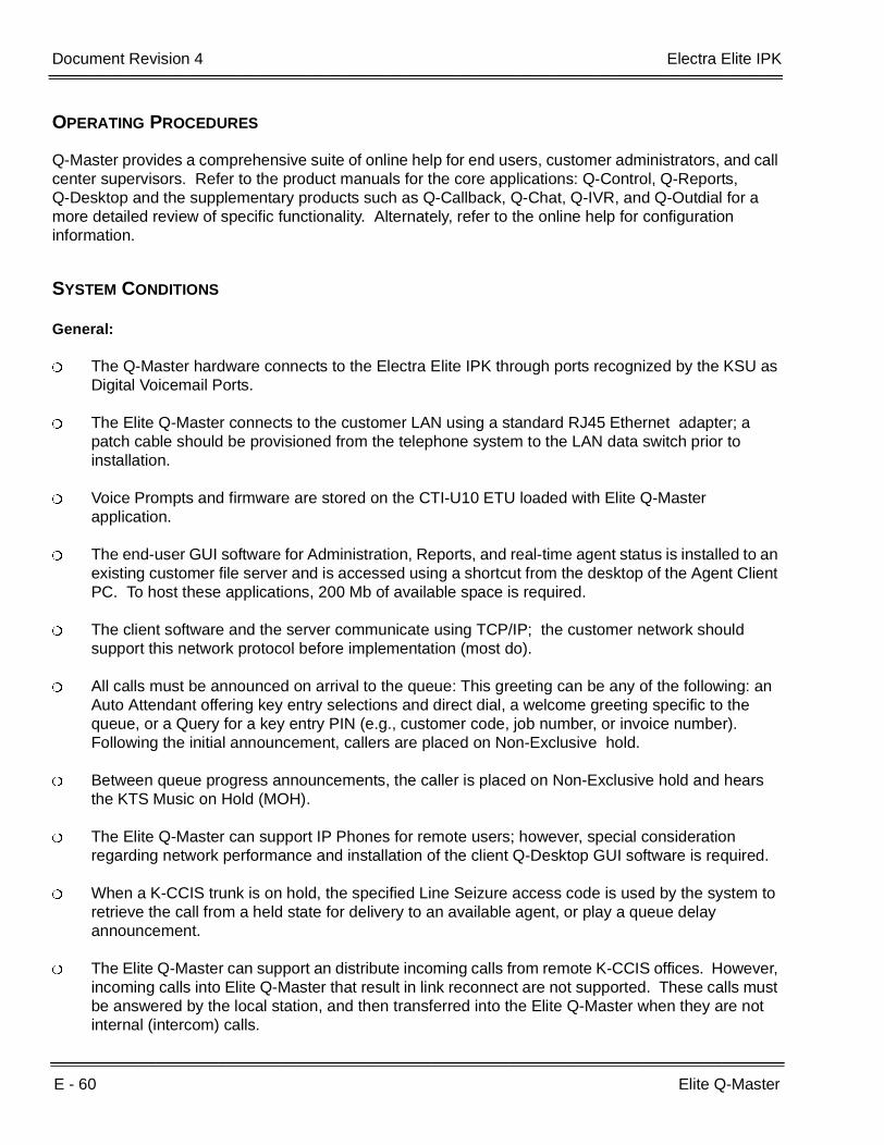
E - 60 Elite Q-Master
___________________________________________________________________________________
___________________________________________________________________________________Document Revision 4 Electra Elite IPK
OPERATING PROCEDURES
Q-Master provides a comprehensive suite of online help for end users, customer administrators, and call center supervisors. Refer to the product manuals for the core applications: Q-Control, Q-Reports, Q-Desktop and the supplementary products such as Q-Callback, Q-Chat, Q-IVR, and Q-Outdial for a more detailed review of specific functionality. Alternately, refer to the online help for configuration information.
SYSTEM CONDITIONS
General:
The Q-Master hardware connects to the Electra Elite IPK through ports recognized by the KSU as Digital Voicemail Ports.
The Elite Q-Master connects to the customer LAN using a standard RJ45 Ethernet adapter; a patch cable should be provisioned from the telephone system to the LAN data switch prior to installation.
Voice Prompts and firmware are stored on the CTI-U10 ETU loaded with Elite Q-Master application.
The end-user GUI software for Administration, Reports, and real-time agent status is installed to an existing customer file server and is accessed using a shortcut from the desktop of the Agent Client PC. To host these applications, 200 Mb of available space is required.
The client software and the server communicate using TCP/IP; the customer network should support this network protocol before implementation (most do).
All calls must be announced on arrival to the queue: This greeting can be any of the following: an Auto Attendant offering key entry selections and direct dial, a welcome greeting specific to the queue, or a Query for a key entry PIN (e.g., customer code, job number, or invoice number). Following the initial announcement, callers are placed on Non-Exclusive hold.
Between queue progress announcements, the caller is placed on Non-Exclusive hold and hears the KTS Music on Hold (MOH).
The Elite Q-Master can support IP Phones for remote users; however, special consideration regarding network performance and installation of the client Q-Desktop GUI software is required.
When a K-CCIS trunk is on hold, the specified Line Seizure access code is used by the system to retrieve the call from a held state for delivery to an available agent, or play a queue delay announcement.
The Elite Q-Master can support an distribute incoming calls from remote K-CCIS offices. However, incoming calls into Elite Q-Master that result in link reconnect are not supported. These calls must be answered by the local station, and then transferred into the Elite Q-Master when they are not internal (intercom) calls.

Electra Elite IPK Document Revision 4
Features and Specifications Manual E - 61
___________________________________________________________________________________
___________________________________________________________________________________
As part of the software installation process, the software must be registered through the internet. This process can be accomplished from the server or from any PC on the customer LAN that has access to both the server and the Internet. The server should be configured for Internet access. The server leaves the factory configured for DHCP and therefore automatically gets this access for most customer installations.
The Elite Q-Master operates as a “Black box” to minimize vulnerability to viruses and simplify the installation. The CTI-U10 ETU loaded with the Elite Q-Master application is not intended to be joined to the customer network domain.
Restrictions:
The Elite Q-Master is factory configured to use the machine name, necqmaster; this name should not be changed. When compliance to a customer computer naming convention is required or where customer has multiple Q-Master installations as part of a wide area network (WAN), please ask the NTAC for assistance before making this change.
ETW Telephones are not supported when Q-Master is used.
Internal (intercom) calls to an Elite Q-Master queue are not supported.
DNIS display is not supported for incoming calls to the Elite Q-Master.
When 5-, 6-, or 7-digit station numbers are used, this feature is not available.
CALL PROCESSING
DESCRIPTION
Abandoned Call Search
Abandoned incoming calls are not connected to agent positions. The system removes them from the queue on trunks that provide calling party disconnect supervision. Q-Reports can be run to provide details of queue abandonment including time of arrival, wait time and (subject to trunk type and telco services provided) Caller Line Identification (CLI/ANI).
Call Transfer to ACD Queue
Trunk calls that terminate to a normal station, ACD agent, or supervisor can be transferred to an ACD queue. Calls must be blind transferred to the queue (the transferring party cannot wait with the caller on line and announce the caller). In some cases, transferred calls may create an extra call record; to ensure accuracy of reporting, the transfer timer or minimum abandon timer must be configured in the Administrator.
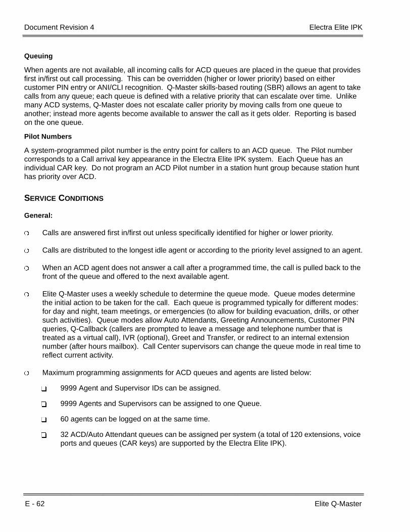
E - 62 Elite Q-Master
___________________________________________________________________________________
___________________________________________________________________________________Document Revision 4 Electra Elite IPK
Queuing
When agents are not available, all incoming calls for ACD queues are placed in the queue that provides first in/first out call processing. This can be overridden (higher or lower priority) based on either customer PIN entry or ANI/CLI recognition. Q-Master skills-based routing (SBR) allows an agent to take calls from any queue; each queue is defined with a relative priority that can escalate over time. Unlike many ACD systems, Q-Master does not escalate caller priority by moving calls from one queue to another; instead more agents become available to answer the call as it gets older. Reporting is based on the one queue.
Pilot Numbers
A system-programmed pilot number is the entry point for callers to an ACD queue. The Pilot number corresponds to a Call arrival key appearance in the Electra Elite IPK system. Each Queue has an individual CAR key. Do not program an ACD Pilot number in a station hunt group because station hunt has priority over ACD.
SERVICE CONDITIONS
General:
Calls are answered first in/first out unless specifically identified for higher or lower priority.
Calls are distributed to the longest idle agent or according to the priority level assigned to an agent.
When an ACD agent does not answer a call after a programmed time, the call is pulled back to the front of the queue and offered to the next available agent.
Elite Q-Master uses a weekly schedule to determine the queue mode. Queue modes determine the initial action to be taken for the call. Each queue is programmed typically for different modes: for day and night, team meetings, or emergencies (to allow for building evacuation, drills, or other such activities). Queue modes allow Auto Attendants, Greeting Announcements, Customer PIN queries, Q-Callback (callers are prompted to leave a message and telephone number that is treated as a virtual call), IVR (optional), Greet and Transfer, or redirect to an internal extension number (after hours mailbox). Call Center supervisors can change the queue mode in real time to reflect current activity.
Maximum programming assignments for ACD queues and agents are listed below:
9999 Agent and Supervisor IDs can be assigned.
9999 Agents and Supervisors can be assigned to one Queue.
60 agents can be logged on at the same time.
32 ACD/Auto Attendant queues can be assigned per system (a total of 120 extensions, voice ports and queues (CAR keys) are supported by the Electra Elite IPK).
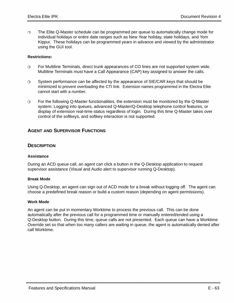
Electra Elite IPK Document Revision 4
Features and Specifications Manual E - 63
___________________________________________________________________________________
___________________________________________________________________________________
The Elite Q-Master schedule can be programmed per queue to automatically change mode for individual holidays or entire date ranges such as New Year holiday, state holidays, and Yom Kippur. These holidays can be programmed years in advance and viewed by the administrator using the GUI tool.
Restrictions:
For Multiline Terminals, direct trunk appearances of CO lines are not supported system wide. Multiline Terminals must have a Call Appearance (CAP) key assigned to answer the calls.
System performance can be affected by the appearance of SIE/CAR keys that should be minimized to prevent overloading the CTI link. Extension names programmed in the Electra Elite cannot start with a number.
For the following Q-Master functionalities, the extension must be monitored by the Q-Master system: Logging into queues, advanced Q-Master/Q-Desktop telephone control features, or display of extension real-time status regardless of login. During this time Q-Master takes over control of the softkeys, and softkey interaction is not supported.
AGENT AND SUPERVISOR FUNCTIONS
DESCRIPTION
Assistance
During an ACD queue call, an agent can click a button in the Q-Desktop application to request supervisor assistance (Visual and Audio alert to supervisor running Q-Desktop).
Break Mode
Using Q-Desktop, an agent can sign out of ACD mode for a break without logging off. The agent can choose a predefined break reason or build a custom reason (depending on agent permissions).
Work Mode
An agent can be put in momentary Worktime to process the previous call. This can be done automatically after the previous call for a programmed time or manually entered/ended using a Q-Desktop button. During this time, queue calls are not presented. Each queue can have a Worktime Override set so that when too many callers are waiting in queue, the agent is automatically denied after call Worktime.

E - 64 Elite Q-Master
___________________________________________________________________________________
___________________________________________________________________________________Document Revision 4 Electra Elite IPK
Logon/Logoff
An agent can log on or off using the Q-Desktop application. Operating statistics are collected until the agent logs off. Agent hot seating is supported because Q-Master tracks agent skill profile and statistics against the agent logon ID instead of the station number. When hot seating is not required, the agent extension can be set to also log non-queue activity when logged on and report inbound/outbound calls for the agent. This feature requires that the always monitor option be selected against the agent extension.
Non-ACD Call
An agent or supervisor can receive a transferred call or a direct trunk call (e.g., Day/Night Ringing, DIT, DID, or Tie line call). Transferred ACD calls from another agent, or ACD queue calls when the caller is placed on hold and subsequently picked up by another agent are considered non-ACD calls.
Headset Answer/Release
An agent using a headset can press a programmed Headset ON/Off Line Key to answer or release an ACD queue call; Q-Master can be set to activate this key automatically for queue calls delivered to the agent.
Headset Volume Control
An agent can control the volume of the headset independent of the volume of the handset.
Monitoring (Barge-In)
The supervisor can monitor agent calls using a key operation on the supervisor terminal. The conference LED can be on or off depending on programming for each terminal involved during monitoring.
SERVICE CONDITIONS
General:
When a call is transferred to the ACD Pilot number using a call appearance key, the LED for that key remains on until the Elite Q-Master answers the call in typically 1~5 seconds depending on the traffic volume.
Call forward and DND do not affect calls offered from Q-Master. An agent with these functions set is still delivered a queue call.
A default alert tone (that can be disabled in system programming) is provided for barge-in monitoring.
An agent in an ACD queue can log out to prevent receiving ACD calls. The station user can then originate calls or receive calls directed to the station number but cannot receive calls from the ACD queue.

Electra Elite IPK Document Revision 4
Features and Specifications Manual E - 65
___________________________________________________________________________________
___________________________________________________________________________________
An agent can log on/off from the telephone using the Q-Master Analog Login feature. The agent dials the analog login number and is answered and prompted for the Agent login ID.
Restrictions:
Incoming ACD queue calls cannot be received when the agent is on break; a queue depth parameter allows calls to deliver through Worktime when callers have been waiting longer than the prescribed threshold.
When an ACD queue call is being offered to an agent and the agent receives a non-ACD call, the queue call is recalled and offered to the next available agent.
When an agent is logged on to Q-Master, softkeys do not function.
ANNOUNCEMENT FUNCTION
DESCRIPTION
There are no Default announcements, Progress announcements, or Position in Queue announcements for the Elite Q-Master. Each announcement can be recorded either using the Administrator application audio editor with audio recorded from the telephone or PC microphone or by importing it from.WAV or. VOX files. Optimum recording settings for studio recordings are available in the online help. Each announcement can be used by any queue. Each announcement can be edited using the Administrator GUI .WAV editor to delete or paste audio content. All announcements are stored in the Q-Master internal database.
SERVICE CONDITIONS
General:
When all agents in the ACD queue are busy, the caller waits in queue until an agent becomes available. In addition to MOH, the caller can receive Welcome and Please Hold progress announcements that can include Position in Queue and Estimated Time to Answer.
Each caller hears every announcement from the beginning; an optional system-wide setting allows callers hearing delay messages to be interrupted and delivered to an agent when one becomes available during a queue progress announcement.
The first announcement is played for the caller even when an agent is available because Q-Master requires a forced announcement for all callers; this can be an Auto Attendant, Welcome Greeting, Request for PIN (Query), or greet and transfer. After initial greeting, the caller is placed on KTS trunk hold and hears the system MOH.
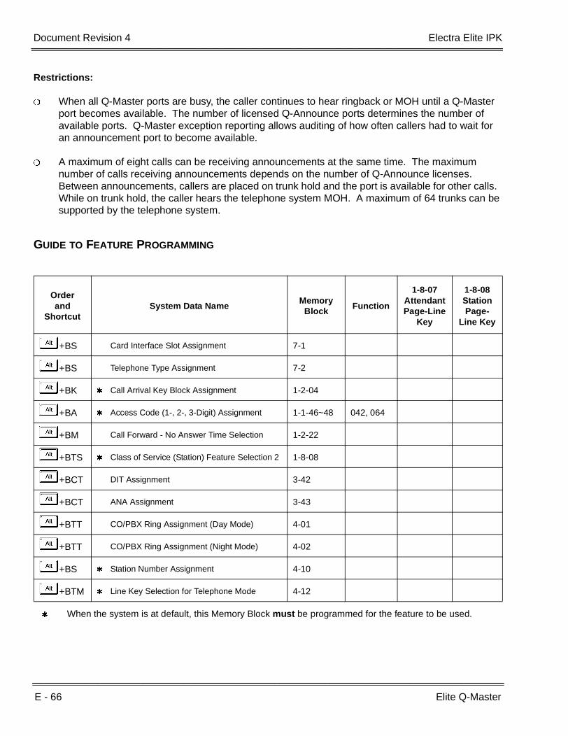
E - 66 Elite Q-Master
___________________________________________________________________________________
___________________________________________________________________________________Document Revision 4 Electra Elite IPK
Restrictions:
When all Q-Master ports are busy, the caller continues to hear ringback or MOH until a Q-Master port becomes available. The number of licensed Q-Announce ports determines the number of available ports. Q-Master exception reporting allows auditing of how often callers had to wait for an announcement port to become available.
A maximum of eight calls can be receiving announcements at the same time. The maximum number of calls receiving announcements depends on the number of Q-Announce licenses. Between announcements, callers are placed on trunk hold and the port is available for other calls. While on trunk hold, the caller hears the telephone system MOH. A maximum of 64 trunks can be supported by the telephone system.
GUIDE TO FEATURE PROGRAMMING
Orderand
ShortcutSystem Data Name
Memory Block
Function
1-8-07AttendantPage-Line
Key
1-8-08StationPage-
Line Key
+BS Card Interface Slot Assignment 7-1
+BS Telephone Type Assignment 7-2
+BK Call Arrival Key Block Assignment 1-2-04
+BA Access Code (1-, 2-, 3-Digit) Assignment 1-1-46~48 042, 064
+BM Call Forward - No Answer Time Selection 1-2-22
+BTS Class of Service (Station) Feature Selection 2 1-8-08
+BCT DIT Assignment 3-42
+BCT ANA Assignment 3-43
+BTT CO/PBX Ring Assignment (Day Mode) 4-01
+BTT CO/PBX Ring Assignment (Night Mode) 4-02
+BS Station Number Assignment 4-10
+BTM Line Key Selection for Telephone Mode 4-12
When the system is at default, this Memory Block must be programmed for the feature to be used.

Electra Elite IPK Document Revision 4
Features and Specifications Manual E - 67
___________________________________________________________________________________
___________________________________________________________________________________
Q-MASTER ELECTRA ELITE/IPK VS. Q-MASTER IPS/IMX
DESCRIPTION
Almost all features of the Q-Master application suite are the same between the NEC systems, and the customer can upgrade from one system to the other with minimal changes. The following table of feature restrictions is provided to highlight functionality between the platforms.
Feature Elite/IPK IPS/IMX Comment
Dialed Number Identification (DNIS) Routing/Reporting
Each DNIS requires a separate queue pilot to enable reporting
Different DNIS/DID/DTI can be directed to the same queue and priority can be adjusted; the call is tagged to identify the dialed destination to the agent and for reporting.
Internal CTI ETU/blade server/multiple servers
Supported for Q-Master Lite, the same ETU is used for announcements and CTI interface for Elite Q-Master installs. An external server is required for installations greater than 15 agents/Desktop, four announce, or when optional modules (e.g., Outdial or IVR) are installed
An internal CTI ETU is not supported; an external server connects using analog extensions (one per announce port) to the PBX OAI TCP/IP interface.
A separate server is recommended for IVR installations, or Enhanced routing because of the nature of customer database interactions required by these modules. The Elite/IPK CTI ETU is an
internal ETU supported by PBX battery backup.
Q-AnnounceSupported on internal Elite/IPK CTI ETU.
External server required with Dialogic/Aculab hardware.
Announce – Initial action for callers.
Q-Announce is required for all installations; every call must be greeted to obtain incoming trunk and caller information. After the initial announcement, callers are placed on PBX hold and hear MOH.
Normal queuing mode is supported to allow a call to be presented to an agent without greeting.
Most customers implement at least a greeting (e.g., Welcome to ACME Co. Your call may be monitored for quality assurance; an associate will be with you shortly).
Telephone Login (without Q-Desktop)
Analog login and Dterm DTMF keys are supported.
Most installation are deployed with Q-Desktop.

E - 68 Elite Q-Master
___________________________________________________________________________________
___________________________________________________________________________________Document Revision 4 Electra Elite IPK
Agents with Analog extensions
Not supported. No CTI visibility of Analog extension activity provided by the CTI link.
Supported – Q-Desktop is recommended.
Announce – IVR maximum capacity
Eight concurrent callers can listen to an announcement or IVR script anytime. Between announcements, callers are placed on hold to allow ports to manage multiple calls.
A maximum of 108 total IVR and Queue Announce ports are supported across up to three servers.
Most customer deployments are between four and 12 ports.Allocation of the functionality is dynamic. Each port can dynamically change from Announce features such as Auto Attendant to IVR as required. The total ports in use any one time for a specific feature depends on the site licenses.
Maximum Concurrent Agents
UP to 60 concurrent agents and supervisors can be logged in anytime. Additional supervisors can run Q- Desktop for call center visibility, but can’t take calls
IPS typically supports up to 150 concurrent agents and supervisors.
The IMX is targeted for call centers for up to 250 concurrent agents.
Concurrent usage licensing is based on active agents logged in to take queue calls or run the Q-Desktop software; These functions are licensed separately.The agent tools, including customer screen pop applications, can normally transition from one PBX platform to another during an upgrade, but product licensing must be applicable to the PBX platform.
Elite Q-Master Lite
Supports up to 15 concurrent agents and Q-Desktop users, plus four ports of Q-Announce and Q-Callback.
Not Available
This is a platform-specific promotion. The customer can upgrade to the standard (complete) Q-Master product license when required.
NEC Q-Master Voice Only
Not Available
Supports up to 100 concurrent agents and a maximum of 10 concurrent Q-Desktop users plus Q-Announce. Does not support Q-Callback.
This is a platform-specific promotion. The customer can upgrade to the standard (complete) Q-Master product license when required.
Q-Fax
Available now and supports multiple separate queues. Same announcement ports are used, but hardware has restrictions for number of concurrent faxes depending on configuration.
Feature Elite/IPK IPS/IMX Comment

Electra Elite IPK Document Revision 4
Features and Specifications Manual E - 69
___________________________________________________________________________________
___________________________________________________________________________________
Redundancy, fallback for PBX CTI link failure
An appearance of the queue CAR key can be programmed on a supervisor telephone with delayed ring. When a CTI link failure occurs, calls can be manually answered and transferred using this key.
The NEC and CTI server handshake; for loss of connectivity, the NEC reverts to FIFO UCD call delivery to a core group of nominated extensions.
When a CTI connectivity fault occurs, calls can be answered manually on all platforms.
Feature Elite/IPK IPS/IMX Comment
E - 70 Elite Q-Master
___________________________________________________________________________________
___________________________________________________________________________________Document Revision 4 Electra Elite IPK
THIS PAGE INTENTIONALLY LEFT BLANK

Features and Specifications Manual E - 71
___________________________________________________________________________________
___________________________________________________________________________________
Emergency 911 – Cut Through E-13
FEATURE DESCRIPTION
When all trunks that belong to the Dial Access Code 9 are busy, and a 911 call is placed, an assigned trunk in the Trunk Group/Route Advance Block is dropped and accessed again by the system to place the 911 call.
SYSTEM AVAILABILITY
Terminal Type:
All Multiline Terminals
Required Components:
None
OPERATING PROCEDURES
To use this feature at any terminal:
1. Lift the handset or press E .
2. Dial I AAor I+ IAA.
3. Talk.
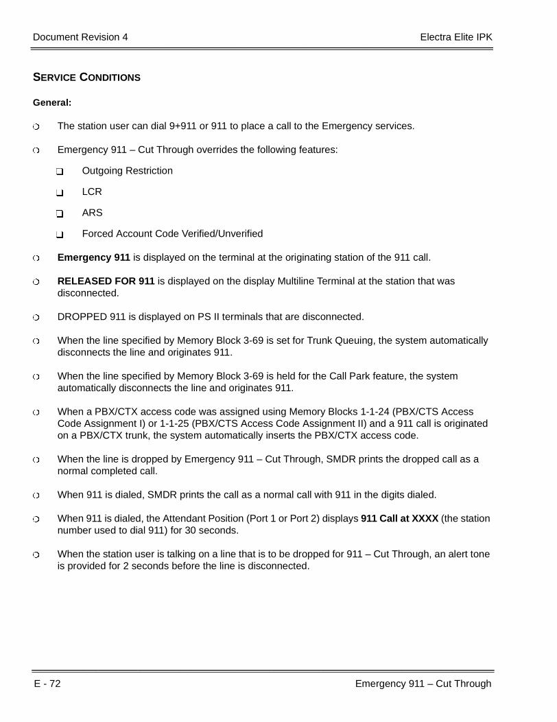
E - 72 Emergency 911 – Cut Through
___________________________________________________________________________________
___________________________________________________________________________________Document Revision 4 Electra Elite IPK
SERVICE CONDITIONS
General:
The station user can dial 9+911 or 911 to place a call to the Emergency services.
Emergency 911 – Cut Through overrides the following features:
Outgoing Restriction
LCR
ARS
Forced Account Code Verified/Unverified
Emergency 911 is displayed on the terminal at the originating station of the 911 call.
RELEASED FOR 911 is displayed on the display Multiline Terminal at the station that was disconnected.
DROPPED 911 is displayed on PS II terminals that are disconnected.
When the line specified by Memory Block 3-69 is set for Trunk Queuing, the system automatically disconnects the line and originates 911.
When the line specified by Memory Block 3-69 is held for the Call Park feature, the system automatically disconnects the line and originates 911.
When a PBX/CTX access code was assigned using Memory Blocks 1-1-24 (PBX/CTS Access Code Assignment I) or 1-1-25 (PBX/CTS Access Code Assignment II) and a 911 call is originated on a PBX/CTX trunk, the system automatically inserts the PBX/CTX access code.
When the line is dropped by Emergency 911 – Cut Through, SMDR prints the dropped call as a normal completed call.
When 911 is dialed, SMDR prints the call as a normal call with 911 in the digits dialed.
When 911 is dialed, the Attendant Position (Port 1 or Port 2) displays 911 Call at XXXX (the station number used to dial 911) for 30 seconds.
When the station user is talking on a line that is to be dropped for 911 – Cut Through, an alert tone is provided for 2 seconds before the line is disconnected.
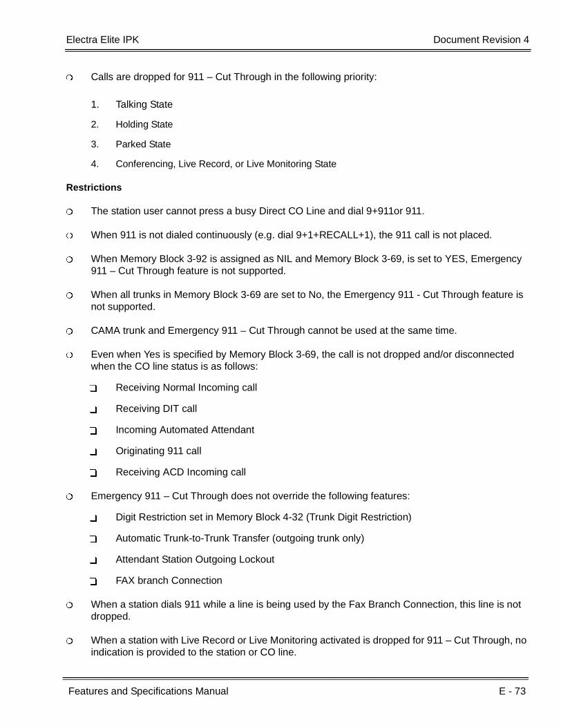
Electra Elite IPK Document Revision 4
Features and Specifications Manual E - 73
___________________________________________________________________________________
___________________________________________________________________________________
Calls are dropped for 911 – Cut Through in the following priority:
1. Talking State
2. Holding State
3. Parked State
4. Conferencing, Live Record, or Live Monitoring State
Restrictions
The station user cannot press a busy Direct CO Line and dial 9+911or 911.
When 911 is not dialed continuously (e.g. dial 9+1+RECALL+1), the 911 call is not placed.
When Memory Block 3-92 is assigned as NIL and Memory Block 3-69, is set to YES, Emergency 911 – Cut Through feature is not supported.
When all trunks in Memory Block 3-69 are set to No, the Emergency 911 - Cut Through feature is not supported.
CAMA trunk and Emergency 911 – Cut Through cannot be used at the same time.
Even when Yes is specified by Memory Block 3-69, the call is not dropped and/or disconnected when the CO line status is as follows:
Receiving Normal Incoming call
Receiving DIT call
Incoming Automated Attendant
Originating 911 call
Receiving ACD Incoming call
Emergency 911 – Cut Through does not override the following features:
Digit Restriction set in Memory Block 4-32 (Trunk Digit Restriction)
Automatic Trunk-to-Trunk Transfer (outgoing trunk only)
Attendant Station Outgoing Lockout
FAX branch Connection
When a station dials 911 while a line is being used by the Fax Branch Connection, this line is not dropped.
When a station with Live Record or Live Monitoring activated is dropped for 911 – Cut Through, no indication is provided to the station or CO line.

E - 74 Emergency 911 – Cut Through
___________________________________________________________________________________
___________________________________________________________________________________Document Revision 4 Electra Elite IPK
Data Assignment
Use Memory Block 1-1-46 [Access Code (1-Digit) Assignment] to Assign Access Code 9 to access the appropriate Trunk Group or Route Advance Block.
Use Memory Block 3-69 (911 Cut Through Trunk Selection) to assign YES to All trunks used for Emergency 911 – Cut Through. Default is all trunks assigned NO.
Use Memory Block 3-91 (Trunk Type Selection) to assign trunk type to all trunks used for Emergency 911 – Cut Through. Default is CO.
Use Memory Block 1-1-24 (PBX/CTX Access Code Assignment 1) and Memory Block 1-1-25 (PBX/CTX Access Code Assistant 2) to assign access codes when CTX/PBX trunks are assigned.
Use Memory Block 3-33 (Disconnect Recognition Time Selection) to assign the time the dropped line remains idle before the line is seized for 911 calls.
GUIDE TO FEATURE PROGRAMMING
Orderand
ShortcutSystem Data Name
Memory Block
Function
1-8-07Attendant
Page-Line Key
1-8-08StationPage-
Line Key
+BA PBX/CTX Access Code Assignment 1 1-1-24
+BA Access Code (1-Digit) Assignment 1-1-46
+BCT Disconnect Recognition Time Selection 3-33
+AE 911 Cut Through Trunk Selection 3-69
+BCT Trunk Type Selection 3-91

Features and Specifications Manual E - 75
___________________________________________________________________________________
___________________________________________________________________________________
Enhanced 911 E-14
FEATURE DESCRIPTION
The Electra Elite IPK system supports Enhanced 911 by defining an available loop start trunk as a CAMA or an ISDN PRI trunk. When a station user dials 911, 9+ 911, or CO line key + 911, the E911 trunk is selected and the Public Safety Answering Point (PSAP) is called. The PSAP is provided callback information generated from the Electra Elite E911 trunk.
The Electra Elite IPK system administrator must maintain and update the callback telephone number database per station.
SYSTEM AVAILABILITY
Terminal Type:
All Multiline Terminals
Required Components:
COI(4)/(8)-U( ), COID(4)/(8)-U( ), COIB(4)/(8)-U( ) or COIB(4)-U20 ETU
PRT(1)-U( ) ETU V2.12 or higher
OPERATING PROCEDURES
To use this feature at any terminal:
1. Lift the handset, and wait for internal dial tone.
2. Dial I AA.
- OR -
Dial I + I AA.
- OR -
Select a CO line key, and dial I AA.

E - 76 Enhanced 911
___________________________________________________________________________________
___________________________________________________________________________________Document Revision 4 Electra Elite IPK
SERVICE CONDITIONS
Restrictions:
The E911 trunk cannot be seized if user dials 911:
after seizing Hot Line.
after answering an incoming call.
after accessing the system using DISA.
during Trunk-to-Trunk Transfer.
The system attendant is not notified when an E911 call is made from the system.
General:
The Caller ID can now be used instead of the CESID. The E911 operator database uses either the CESID or Caller ID to provide a callback number and location for emergency response.
A system that provides service to a different address using OPX circuits must provide a specific CESID for that station. The CESID is provided by the TELCO when the OPX circuit is provided. The KTS administrator must file a callback number along with this CESID to the E911 system that then places this information in the E911 system database.
When the E911 trunk is busy, the system allows the call to be routed over another trunk. This is software selectable. No Alternate Routing is the default (with a warning not to change it to Allow) because of the concern that under catastrophic conditions a single location could overload the emergency system with multiple 911 calls.
When a call is originated using Enhanced 911, the CAMA or ISDN PRI trunk is seized even when a CESID code is not registered.
The E911 trunk should not be assigned to a line key, trunk group, route advance block, Specified Tenant on CO/PBX/Centrex Line Seizure (1- or 2-digit), or Outgoing (CO only) Access in Same Tenant.
Enhanced 911 is available only when a CAMA or ISDN PRI trunk is connected and assigned to the system.
The Facility Interface Code (FIC) for a dedicated CAMA or ISDN PRI trunk is 02RV-O. This code is provided when service is ordered to indicate the trunk type.
The following features cannot restrict the station ability to dial 911:
Account Code – Forced/Verified/Unverified
Station Outgoing Lockout
LCR
Caller ID Blocking

Electra Elite IPK Document Revision 4
Features and Specifications Manual E - 77
___________________________________________________________________________________
___________________________________________________________________________________
GUIDE TO FEATURE PROGRAMMING
Enhanced 911 (CAMA Trunk)
Orderand
ShortcutSystem Data Name
Memory Block
Function
1-8-07AttendantPage-Line
Key
1-8-08StationPage-
Line Key
+BS Card Interface Slot Assignment 7-1
+AE 911-Cut Through Trunk Selection 3-69
+AE Enhanced 911 Trunk Assignment 1-8-43
+AE Enhanced 911 Alternate Route Assignment 1-8-44
+AEEnhanced 911 Alternate Route Assignment (Maintenance Busy)
1-8-45
+AE Enhanced 911 Dialing Digit Assignment 1-8-46
+AEEnhanced 911 CESID to Station Table Assignment
4-54
+BCT Trunk-to-Trunk Group Assignment 3-03
Enhanced 911 (ISDN PRI)
Orderand
ShortcutSystem Data Name
Memory Block
Function
1-8-07AttendantPage-Line
Key
1-8-08StationPage-
Line Key
+AE 911-Cut Through Trunk Selection 3-69
+AE Enhanced 911 Trunk Assignment 1-8-43
+AE Enhanced 911 Alternate Route Assignment 1-8-44
+AEEnhanced 911 Alternate Route Assignment (Maintenance Busy)
1-8-45
+AE Enhanced 911 Dialing Digit Assignment 1-8-46
+AEEnhanced 911 CESID to Station Table Assignment
4-54
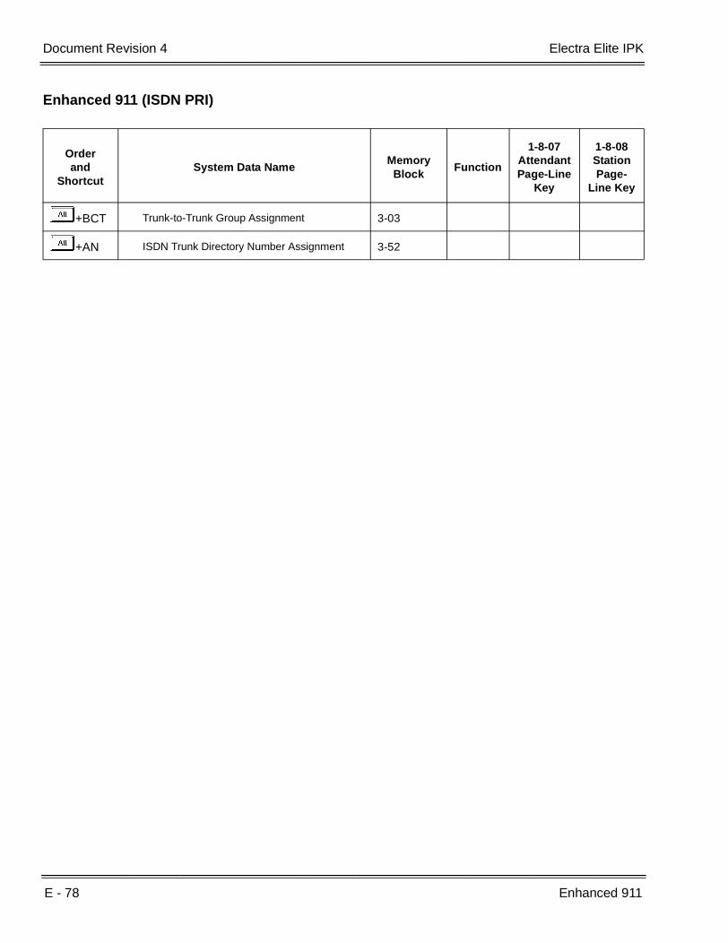
E - 78 Enhanced 911
___________________________________________________________________________________
___________________________________________________________________________________Document Revision 4 Electra Elite IPK
+BCT Trunk-to-Trunk Group Assignment 3-03
+AN ISDN Trunk Directory Number Assignment 3-52
Enhanced 911 (ISDN PRI)
Orderand
ShortcutSystem Data Name
Memory Block
Function
1-8-07AttendantPage-Line
Key
1-8-08StationPage-
Line Key
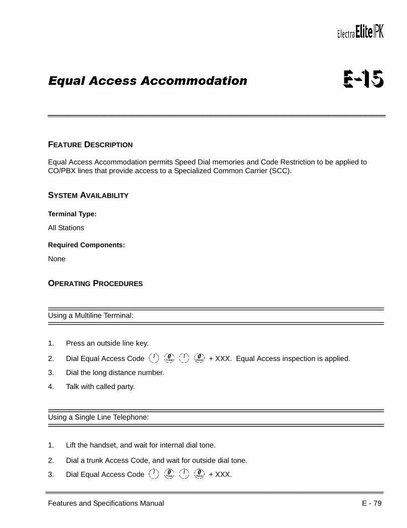
Features and Specifications Manual E - 79
___________________________________________________________________________________
___________________________________________________________________________________
Equal Access Accommodation E-15
FEATURE DESCRIPTION
Equal Access Accommodation permits Speed Dial memories and Code Restriction to be applied to CO/PBX lines that provide access to a Specialized Common Carrier (SCC).
SYSTEM AVAILABILITY
Terminal Type:
All Stations
Required Components:
None
OPERATING PROCEDURES
Using a Multiline Terminal:
1. Press an outside line key.
2. Dial Equal Access Code AKAK + XXX. Equal Access inspection is applied.
3. Dial the long distance number.
4. Talk with called party.
Using a Single Line Telephone:
1. Lift the handset, and wait for internal dial tone.
2. Dial a trunk Access Code, and wait for outside dial tone.
3. Dial Equal Access Code AKAK + XXX.

E - 80 Equal Access Accommodation
___________________________________________________________________________________
___________________________________________________________________________________Document Revision 4 Electra Elite IPK
4. Dial the applicable long distance number. Code Restriction inspection is applied.
5. Talk with called party.
SERVICE CONDITIONS
General:
Code Restriction applies after an Other Common Carrier (OCC) code is dialed.
RELATED FEATURES LIST
GUIDE TO FEATURE PROGRAMMING
Feature Number
Feature Name
C-21 Code Restriction
C-22 CO/PBX, Tie Line Digit Restriction
Orderand
ShortcutSystem Data Name
Memory Block
Function
1-8-07AttendantPage-Line
Key
1-8-08StationPage-
Line Key
+AC OCC Table Assignment 1-1-67
+AC OCC Table to Trunk Group Assignment 5-03
+AC 8-Digit Matching Table to OCC Table Assignment
1-1-68
+AC Code Restriction Class Assignment (Day Mode)
4-07
+AC Code Restriction Class Assignment (Night Mode)
4-08
+AC 8-Digit Matching Table to Class Assignment 1-1-61
When the system is at default this Memory Block must be programmed for the feature to be used.
Features and Specifications Manual E - 81
___________________________________________________________________________________
___________________________________________________________________________________
External Tone Ringer E-16
FEATURE DESCRIPTION
The External Tone Ringer provides a common audible tone with relay contacts for control when incoming CO/PBX calls are received in Day or Night Mode. The relay contact closures may be used for external bells or chimes. When an Attendant is not available, station users may respond to the external ring and answer incoming calls. This feature provides wide area coverage or loud ringing for noisy locations where incoming CO/PBX calls are answered.
SYSTEM AVAILABILITY
Terminal Type:
Not applicable
Required Components:
ECR-U( ) ETU for common audible and control relays
OPERATING PROCEDURES
None
SERVICE CONDITIONS
General:
An ECR-U( ) ETU is required for common audible and control relays (10 relays are provided).
The external ringing equipment must be locally provided.
Incoming calls to an External Tone Ringer can be answered by Call Pickup (Intratenant/Intertenant).

E - 82 External Tone Ringer
___________________________________________________________________________________
___________________________________________________________________________________Document Revision 4 Electra Elite IPK
Restrictions:
A maximum of four relays are programmable for External Tone Ringer control.
Tie lines, DIT/ANA calls, and DID trunks do not activate the External Tone Ringer control relays.
The External Tone Ringer does not operate on a trunk that is not assigned to a Tenant group.
GUIDE TO FEATURE PROGRAMMING
Orderand
ShortcutSystem Data Name
Memory Block
Function
1-8-07AttendantPage-Line
Key
1-8-08StationPage-
Line Key
+BS Card Interface Slot Assignment 7-1
+BP General Purpose Relay Assignment 1-8-37
+BN ECR Relay to Tenant Assignment 2-08
+BP External Ring Relay Cycle Selection 1-7-07
When the system is at default this Memory Block must be programmed for the feature to be used.
Features and Specifications Manual E - 83
___________________________________________________________________________________
___________________________________________________________________________________
External Zone Paging (Meet-Me) E-17
FEATURE DESCRIPTION
External Zone Paging (Meet-Me) allows up to three zones of External Zone Paging plus All Zone External Paging. The user can locate personnel quickly using external paging. An external speaker can be installed in a noisy area where a telephone would not be appropriate. All Zone External Paging enables emergency announcements to be made to all areas quickly. The Meet-Me function allows the paged party to respond quickly to the paged call.
With the Electra Elite IPK system, a single external paging zone output is built into and provided with the basic B64-U( ) KSU.
SYSTEM AVAILABILITY
Terminal Type:
All Stations
Required Components:
ECR-U( ) ETU for Zone Paging
1- or 2-way amplifier and speakers
OPERATING PROCEDURES
To originate using a Multiline Terminal:
1. Lift the handset.
2. Dial the Access CodeEE~EI (as set in default) for the required zone, or press the programmed Feature Access or One-Touch key.

E - 84 External Zone Paging (Meet-Me)
___________________________________________________________________________________
___________________________________________________________________________________Document Revision 4 Electra Elite IPK
To answer using a Multiline Terminal:
1. Lift the handset.
2. Dial the Meet-Me Access Code (EJ, when the page is an Internal/External Page, or EL, when the page is an External Page, as set in default), or press the programmed Feature Access or One-Touch key.
To originate using a Single Line Telephones:
1. Lift the handset.
2. Dial the desired Access Code EE~EI(as set in default) for the required zone.
To answer using a Single Line Telephones:
1. Lift the handset.
2. Dial the Meet-Me Access Code (EJ, when the page is an Internal/External Page, or EL, when the page is only an External Page, as set in default).
SERVICE CONDITIONS
General:
Default Access Codes are:
After a page is established and the Meet-Me code is dialed, the paging circuit is released and another party may page.
All External Zones 55
External Zone A 56
External Zone B 57
External Zone C 58
All Internal/External Zones 59 Default Access Codes can be changed during installation.
External Meet-Me 5#
Internal Meet-Me 5

Electra Elite IPK Document Revision 4
Features and Specifications Manual E - 85
___________________________________________________________________________________
___________________________________________________________________________________
A Multiline Terminal user can conference an outside line with an External Zone Page to allow a conversation to be monitored by people within speaker range.
Talk Back Paging is supported.
Restrictions:
When an External Zone Page is in progress (either Zone A, B, C, or All Zone), no other station can activate External Zone Paging until all zones become idle again.
The built-in single external paging zone output with the Electra Elite IPK, B64-U( ) KSU, can provide a pre-alert tone if assigned. The Chime control (4-Tone Chime) is not supported.
Only three external paging zones and All Zone external Paging are possible.
RELATED FEATURES LIST
GUIDE TO FEATURE PROGRAMMING
Feature Number
Feature Name
B-1 Background Music Over External Speakers
Orderand
ShortcutSystem Data Name
Memory Block
Function
1-8-07AttendantPage-Line
Key
1-8-08StationPage-
Line Key
+BS Card Interface Slot Assignment 7-1
+BAAccess Code (1-, 2-, or 3-Digit) Assignment 1-1-46/47/
48074 ~079,081
+BTD Attendant Add-On Console Key Assignment 1-6-05
+BP External Speaker Connection Selection 1-7-02
+BP External Paging Alert Tone Selection 1-7-03
+BP External Paging Timeout Selection 1-7-06
+BP External Speaker Pre-Tone/Chime Selection 1-7-08
+BP External Speaker Chime Start Time Selection 1-7-09
+BTM Line Key Selection for Telephone Mode 4-12
+AC Station to Timer Class of Service 4-71

E - 86 External Zone Paging (Meet-Me)
___________________________________________________________________________________
___________________________________________________________________________________Document Revision 4 Electra Elite IPK
THIS PAGE INTENTIONALLY LEFT BLANK

Features and Specifications Manual F - 1
___________________________________________________________________________________
___________________________________________________________________________________
Facsimile CO Branch Connection F-1
FEATURE DESCRIPTION
The Electra Elite IPK system provides branch connection of locally provided facsimile machines to CO/PBX lines. Additional dedicated CO/PBX lines are not required for a facsimile to operate. The facsimile shares the last CO/PBX line on the COI(4)-U( ) ETU, or COIB(4)-U( ) ETU through the Main Distribution Frame (MDF) where the CO line is connected from TELCO.
SYSTEM AVAILABILITY
Terminal Type:
Not Applicable
Required Components:
COI(4)-U( ) ETU or COIB(4)-U( ) ETU
OPERATING PROCEDURES
None
SERVICE CONDITIONS
General:
The Electra Elite IPK systems require a COI(4)-U( ) ETU or COIB(4)-U( ) ETU to connect a facsimile in branch to a direct CO/PBX line.
Connection of the facsimile machine does not require extra system ports.
The Electra Elite IPK systems cannot distinguish between an incoming facsimile call and a CO/PBX call. Ringing assignments should be turned off for fax lines.

F - 2 Facsimile CO Branch Connection
___________________________________________________________________________________
___________________________________________________________________________________Document Revision 4 Electra Elite IPK
A facsimile call terminating at the CO/PBX line where the Fax Branch Unit is connected in branch is automatically answered by the Fax machine. Delayed Ringing Line assignment to stations for the Fax Branch Line are recommended.
When the facsimile is in use, the loop detection information turns on the associated CO/PBX line key LED on a Multiline Terminal.
When the facsimile is not in use, the Fax Branch CO/PBX line can be used as an outside line.
Code restriction does not apply to outgoing calls from the Fax machine.
Restrictions:
For this feature to work properly using the COIB(4)-U10 ETU, switch SW400 must be set to Loop Start (LP).
RELATED FEATURES LIST
GUIDE TO FEATURE PROGRAMMING
Feature Number
Feature Name
L-6 Loop Start Trunks
U-5 Universal Slots
Orderand
ShortcutSystem Data Name
Memory Block
Function
1-8-07AttendantPage-Line
Key
1-8-08StationPage-
Line Key
+BN Line Key Selection 2-05
+BN Line Key Selection for Tenant Mode 2-06
+BTT CO/PBX Ring Assignment (Day Mode) 4-01
+BTT CO/PBX Ring Assignment (Night Mode) 4-02
+BTM Line Key Selection for Telephone Mode 4-12
+BS Card Interface Slot Assignment 7-1
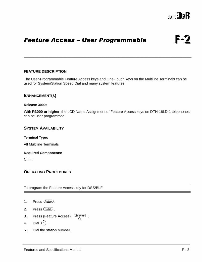
Features and Specifications Manual F - 3
___________________________________________________________________________________
___________________________________________________________________________________
Feature Access – User Programmable F-2
FEATURE DESCRIPTION
The User-Programmable Feature Access keys and One-Touch keys on the Multiline Terminals can be used for System/Station Speed Dial and many system features.
ENHANCEMENT(S)
Release 3000:
With R3000 or higher, the LCD Name Assignment of Feature Access keys on DTH-16LD-1 telephones can be user programmed.
SYSTEM AVAILABILITY
Terminal Type:
All Multiline Terminals
Required Components:
None
OPERATING PROCEDURES
To program the Feature Access key for DSS/BLF:
1. Press A .
2. Press B .
3. Press (Feature Access)W. 4. Dial A.
5. Dial the station number.

F - 4 Feature Access – User Programmable
___________________________________________________________________________________
___________________________________________________________________________________Document Revision 4 Electra Elite IPK
6. Dial A (optional step, refer to Note).
Dial Ato switch the call from Voice to Tone or Tone to Voice.
7. Press A .
To program the Feature Access key for Station Speed Dial:
1. Press A .
2. Press B .
3. Press (Feature Access)W.
4. Dial K.
5. Dial the Trunk or Trunk Group Access Code (maximum 4 digits).
6. Dial the telephone number to be dialed.
7. Press A .
To program the Feature Access key for a dial code feature:
1. Press A .
2. Press B .
3. Press (Feature Access)W.
4. Dial A.
5. Dial the station number.
6. Press A .
To program a Feature Access key for a Feature key + code feature:
1. Press A .
2. Press B .
3. Press (Feature Access)W.
4. DialL. The L indicates A to the Electra Elite system.
5. Dial the Feature Access Code.
6. Press A .
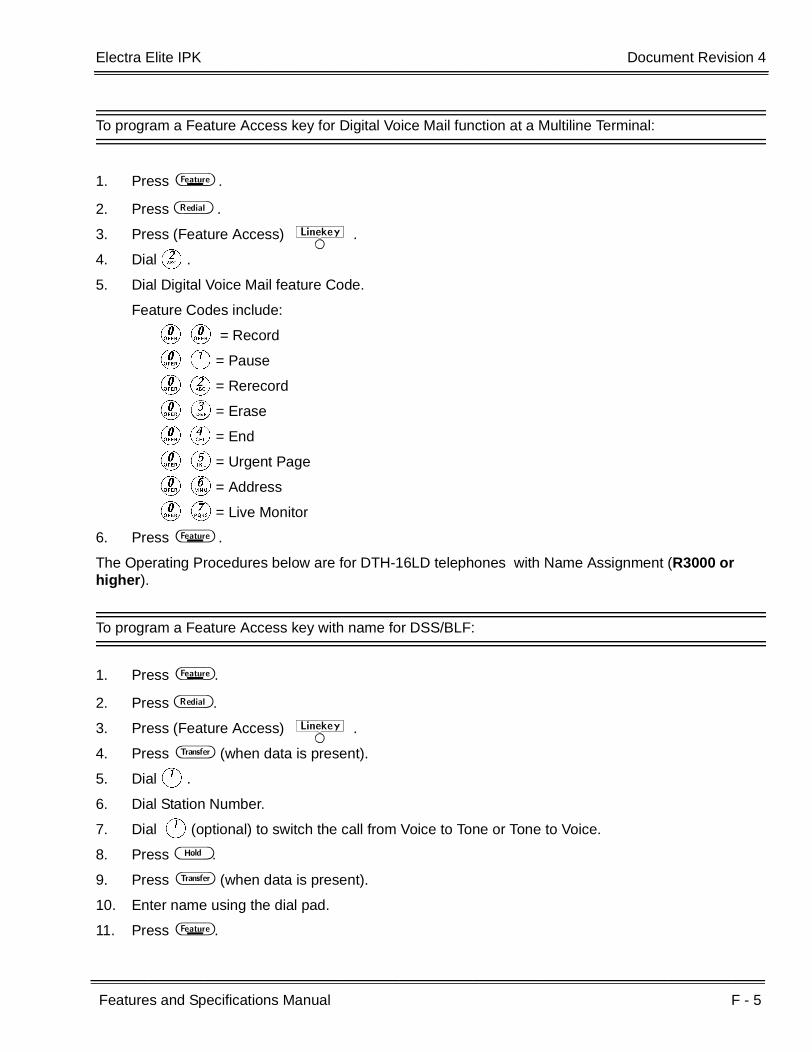
Electra Elite IPK Document Revision 4
Features and Specifications Manual F - 5
___________________________________________________________________________________
___________________________________________________________________________________
To program a Feature Access key for Digital Voice Mail function at a Multiline Terminal:
1. Press A .
2. Press B .
3. Press (Feature Access)W.
4. DialB.
5. Dial Digital Voice Mail feature Code.
Feature Codes include:
KK = Record
KA= Pause
KB= Rerecord
KC= Erase
KD= End
KE= Urgent Page
KF= Address
KG= Live Monitor
6. Press A .
The Operating Procedures below are for DTH-16LD telephones with Name Assignment (R3000 or higher).
To program a Feature Access key with name for DSS/BLF:
1. Press A .
2. Press B .
3. Press (Feature Access)W.
4. Press G (when data is present).
5. DialA.
6. Dial Station Number.
7. Dial A(optional) to switch the call from Voice to Tone or Tone to Voice.
8. Press H .
9. Press G (when data is present).
10. Enter name using the dial pad.
11. Press A .

F - 6 Feature Access – User Programmable
___________________________________________________________________________________
___________________________________________________________________________________Document Revision 4 Electra Elite IPK
To program a Feature Access key with name for Station Speed Dial:
1. Press A .
2. Press B .
3. Press (Feature Access) W.
4. Press G (when data is present).
5. DialK.
6. Dial Trunk or Trunk Group Access Code (maximum of four digits).
7. Dial telephone number to be dialed.
8. Press H .
9. Press G (when data is present).
10. Enter name using the dial pad.
11. Press A .
To program a Feature Access key with name for a dial code feature:
1. Press A .
2. Press B .
3. Press (Feature Access) W.
4. Press G (when data is present).
5. DialA.
6. Dial the station number.
7. Press H .
8. Press G (when data is present).
9. Enter name using the dial pad.
10. Press A .
To program a Feature Access key with name for a Feature Key +code feature:
1. Press A .
2. Press B .
3. Press (Feature Access) W.
4. Press G (when data is present).

Electra Elite IPK Document Revision 4
Features and Specifications Manual F - 7
___________________________________________________________________________________
___________________________________________________________________________________
5. DialL (indicates Feature to the Electra Elite IPK system).
6. Dial Feature Access Code.
7. Press H .
8. Press G (when data is present).
9. Enter name using the dial pad.
10. Press A .
To program a Feature Access key with name Digital Voice Mail function:
1. Press A .
2. Press B .
3. Press (Feature Access) W.
4. Press G (when data is present).
5. DialB.
6. Dial Digital Voice Mail feature Code.
Feature Codes include:
KK = Record
KA= Pause
KB= Rerecord
KC= Erase
KD= End
KE= Urgent Page
KF= Address
KG= Live Monitor
7. Press H .
8. Press G (when data is present).
9. Enter name using the dial pad.
10. Press A .
SERVICE CONDITIONS
General:
Line keys, not used for CO/PBX line access, may be assigned as Feature Access keys in System Programming. The user can then program the Feature Access keys for Speed Dial, DSS/BLF, and selected features (e.g., Call Pickup, Paging, DND set, or DND cancel).

F - 8 Feature Access – User Programmable
___________________________________________________________________________________
___________________________________________________________________________________Document Revision 4 Electra Elite IPK
Each Feature Access key can store up to 16 digits.
When programming Feature Access or One-Touch keys, press the Answer key, then press: Recall, Feature, Conf, Redial, Speaker, Answer, Transfer, or Hold to enter and store the applicable feature keys.
Feature Access keys and One-Touch keys are similar in purpose and ability. Unused Line keys can be assigned as Feature Access keys. One-Touch key availability is controlled by the type of Multiline Terminal.
General: (for LCD Name Assignment of Feature Access keys on DTH-16LD-1 telephones by userprogramming)
UP to eight characters can be assigned for DTH-16LD-1 Telephones with Name assignment with Name assignment.
The feature key code for DTH-16LD-1 Telephones with Name assignment can be changed without changing or erasing the name assigned to the Feature Access key, and the feature key Name can be changed/edited without changing or erasing the feature key code assigned to the Feature Access key.
When user is programming Feature Access keys on DTH-16LD-1 Telephones, The Transfer key is used to delete data that is present.
When user is programming Feature Access keys on DTH-16LD-1 Telephones, The Conf key is used to backspace/delete existing data one character at a time.
When a user programs or modifies a Name for a Feature Access key, changes are displayed in Memory Block 4-68 (LCD Line Key – Name Assignment).
Restrictions: (for LCD Name Assignment of Feature Access keys on DTH-16LD-1 telephones by userprogramming)
Only line keys assigned as Feature Access keys allow user to program Name for DTH-16LD-1 Telephones with Name assignment.

Electra Elite IPK Document Revision 4
Features and Specifications Manual F - 9
___________________________________________________________________________________
___________________________________________________________________________________
RELATED FEATURES LIST
GUIDE TO FEATURE PROGRAMMING
Feature Number
Feature Name
D-13 Direct Station Selection (DSS)
F-3 Flexible Line Assignment
N-2 Nesting Dial
O-3 One-Touch Feature Access
S-11 Speed Dial – Station
S-13 Speed Dial – System
U-7 User Programming Ability
Orderand
ShortcutSystem Data Name
Memory Block
Function
1-8-07AttendantPage-Line
Key
1-8-08StationPage-
Line Key
+BN Line Key Selection 2-05
+BN Line Key Selection for Tenant Mode 2-06
+BTM Line Key Selection for Telephone Mode 4-12

F - 10 Feature Access – User Programmable
___________________________________________________________________________________
___________________________________________________________________________________Document Revision 4 Electra Elite IPK
THIS PAGE INTENTIONALLY LEFT BLANK

Features and Specifications Manual F - 11
___________________________________________________________________________________
___________________________________________________________________________________
Flexible Line Assignment F-3
FEATURE DESCRIPTION
Each Multiline Terminal has complete flexibility of line key assignments to meet individual needs. Functions can be programmed on Flexible Line Keys, including DSS numbers and a variety of Feature Access Codes to simplify the use of these functions. Outside line appearances and Secondary Incoming Extensions can also be assigned to Flexible Line keys.
SYSTEM AVAILABILITY
Terminal Type:
All Multiline Terminals
Required Components:
None
OPERATING PROCEDURES
None
SERVICE CONDITIONS
General:
Each Flexible Line key can be assigned one of the following options:
NON (not assigned)
CO Outside Lines (01~64)
Trunk Groups (01~32)
Route Advance Blocks (01~32)
Call Appearance keys (for Groups 00~47, Locations 01~24)
Feature Access keys (01~16)
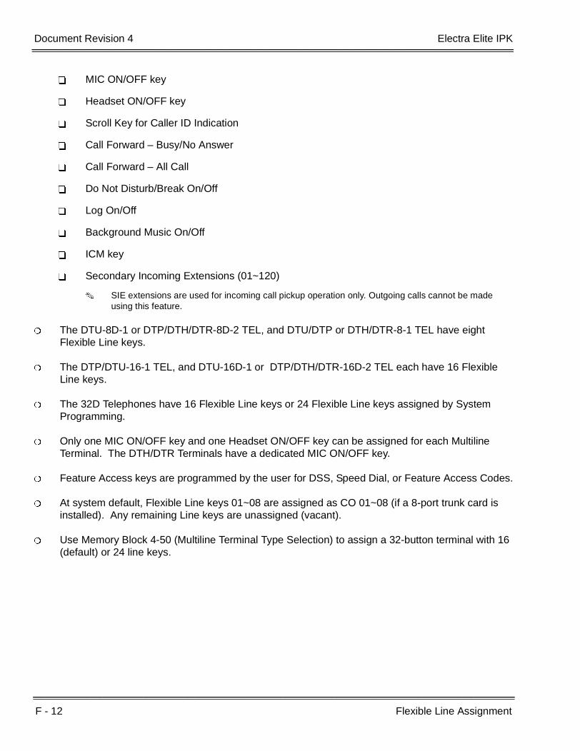
F - 12 Flexible Line Assignment
___________________________________________________________________________________
___________________________________________________________________________________Document Revision 4 Electra Elite IPK
MIC ON/OFF key
Headset ON/OFF key
Scroll Key for Caller ID Indication
Call Forward – Busy/No Answer
Call Forward – All Call
Do Not Disturb/Break On/Off
Log On/Off
Background Music On/Off
ICM key
Secondary Incoming Extensions (01~120)
SIE extensions are used for incoming call pickup operation only. Outgoing calls cannot be made using this feature.
The DTU-8D-1 or DTP/DTH/DTR-8D-2 TEL, and DTU/DTP or DTH/DTR-8-1 TEL have eight Flexible Line keys.
The DTP/DTU-16-1 TEL, and DTU-16D-1 or DTP/DTH/DTR-16D-2 TEL each have 16 Flexible Line keys.
The 32D Telephones have 16 Flexible Line keys or 24 Flexible Line keys assigned by System Programming.
Only one MIC ON/OFF key and one Headset ON/OFF key can be assigned for each Multiline Terminal. The DTH/DTR Terminals have a dedicated MIC ON/OFF key.
Feature Access keys are programmed by the user for DSS, Speed Dial, or Feature Access Codes.
At system default, Flexible Line keys 01~08 are assigned as CO 01~08 (if a 8-port trunk card is installed). Any remaining Line keys are unassigned (vacant).
Use Memory Block 4-50 (Multiline Terminal Type Selection) to assign a 32-button terminal with 16 (default) or 24 line keys.
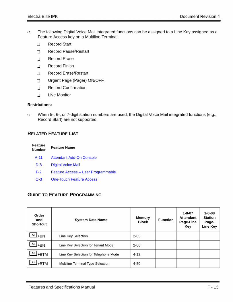
Electra Elite IPK Document Revision 4
Features and Specifications Manual F - 13
___________________________________________________________________________________
___________________________________________________________________________________
The following Digital Voice Mail integrated functions can be assigned to a Line Key assigned as a Feature Access key on a Multiline Terminal:
Record Start
Record Pause/Restart
Record Erase
Record Finish
Record Erase/Restart
Urgent Page (Pager) ON/OFF
Record Confirmation
Live Monitor
Restrictions:
When 5-, 6-, or 7-digit station numbers are used, the Digital Voice Mail integrated functions (e.g., Record Start) are not supported.
RELATED FEATURE LIST
GUIDE TO FEATURE PROGRAMMING
Feature Number
Feature Name
A-11 Attendant Add-On Console
D-8 Digital Voice Mail
F-2 Feature Access – User Programmable
O-3 One-Touch Feature Access
Orderand
ShortcutSystem Data Name
Memory Block
Function
1-8-07AttendantPage-Line
Key
1-8-08StationPage-
Line Key
+BN Line Key Selection 2-05
+BN Line Key Selection for Tenant Mode 2-06
+BTM Line Key Selection for Telephone Mode 4-12
+BTM Multiline Terminal Type Selection 4-50

F - 14 Flexible Line Assignment
___________________________________________________________________________________
___________________________________________________________________________________Document Revision 4 Electra Elite IPK
THIS PAGE INTENTIONALLY LEFT BLANK
Features and Specifications Manual F - 15
___________________________________________________________________________________
___________________________________________________________________________________
Flexible Numbering Plan F-4
FEATURE DESCRIPTION
A Flexible Numbering Plan is automatically assigned by the Resident System Program when the system power is first turned on. The Station Numbering Plan may be changed using System Programming to fit customer needs. A station can be assigned a 2-, 3-, or 4-digit station number. An Automated Attendant Numbering Plan is also available with the Flexible Numbering Plan.
ENHANCEMENT(S)
With Release R2500, the Electra Elite IPK can support 2~7-digit station numbers that can be assigned by the 10s group for 4-digit station numbers, by the 100s group for 5-digit station numbers, by the 1,000s group for 6-digit station numbers, or by the 10,000s group for 7-digit station numbers.
SYSTEM AVAILABILITY
Terminal Type:
All Stations
Required Components:
None
OPERATING PROCEDURES
None
SERVICE CONDITIONS
General:
The default station numbers are 100~399 (depending on system configuration).
Refer to the Electra Elite IPK Programming Manual for the Numbering Plan Access Code defaults.
Automated Attendant/DISA Numbering Plan, and Uniform Numbering plan can be assigned.

F - 16 Flexible Numbering Plan
___________________________________________________________________________________
___________________________________________________________________________________Document Revision 4 Electra Elite IPK
Restrictions:
When Voice Mail Message waiting is required to be sent across the K-CCIS link to a remote station, the Closed Number Blocks must be used.
Extension numbers cannot start with 0 or 9.
Only one Station Numbering Plan can be used at a time.
Station Numbering Plan can be 2, 3, or 4 digits (R2000 or lower).
With R2000 or lower, station numbers are assigned by the 100s group for 4-digit station numbers.
When 5-, 6-, or 7-digit station numbers are used, the following example shows how the assignment is made for Station Number Port 01 with a 7-digit station number of 7650000:
Memory Block 1-2-03 (2~7-digit Station Number Selection) set to 7 digits
Memory Block 1-2-34 (Expanded Station Number Assignment) set to 765
Memory Block 1-1-46 [Access Code (1-digit) Assignment], No ACs, set to 001
Memory Block 1-1-47 [Access Code (2-digit) Assignment], AC 76, set to 301
Memory Block 1-1-48 [Access Code (3-digit) Assignment], Table 1, Dial No. 5, set to 001
Memory Block 4-10 (Station Number Assignment) Port 01 set to 0000
The following features are not supported or have limitations when 5-, 6-, or 7-digit station numbers are used.
Feature Comment
Account Code Entry Only the last four digits of the extension are printed when 5-, 6-, or 7-digit station numbers are used.
Account Code – Forced/Verified/ Unverified
Only the last four digits of the extension are printed when 5-, 6-, or 7-digit station numbers are used.
Add-On Conference Only the last four digits of the extension are printed when 5-, 6-, or 7-digit station numbers are used.
Station Number Port 01 = 765 0000
Assigned in Memory Block 4-10.
Assigned in Memory Block 1-2-34
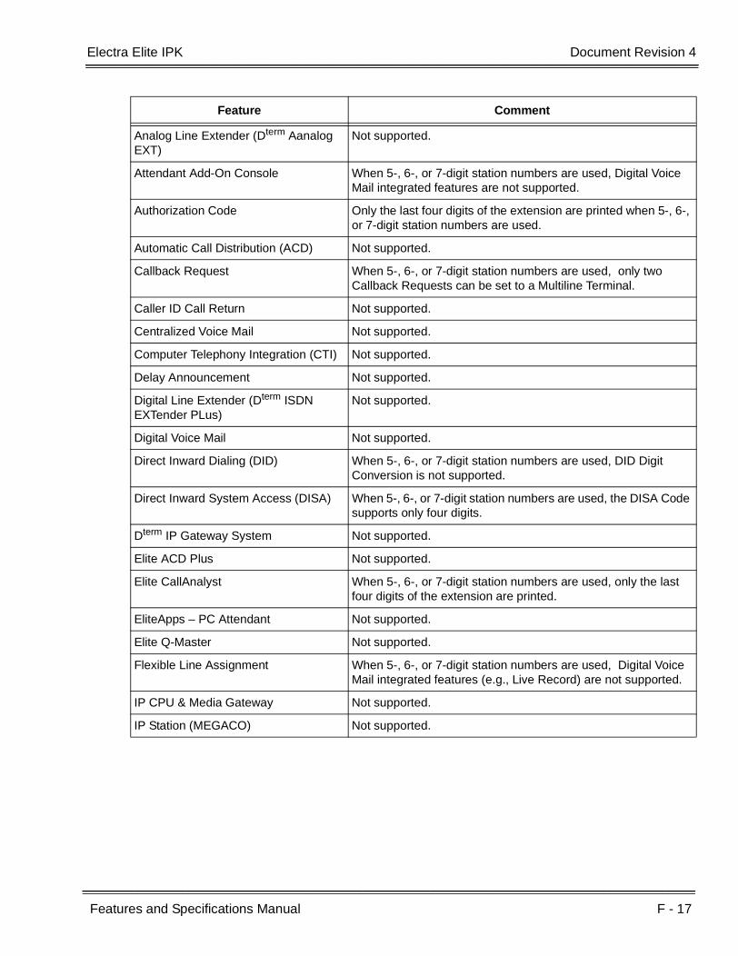
Electra Elite IPK Document Revision 4
Features and Specifications Manual F - 17
___________________________________________________________________________________
___________________________________________________________________________________
Analog Line Extender (Dterm Aanalog EXT)
Not supported.
Attendant Add-On Console When 5-, 6-, or 7-digit station numbers are used, Digital Voice Mail integrated features are not supported.
Authorization Code Only the last four digits of the extension are printed when 5-, 6-, or 7-digit station numbers are used.
Automatic Call Distribution (ACD) Not supported.
Callback Request When 5-, 6-, or 7-digit station numbers are used, only two Callback Requests can be set to a Multiline Terminal.
Caller ID Call Return Not supported.
Centralized Voice Mail Not supported.
Computer Telephony Integration (CTI) Not supported.
Delay Announcement Not supported.
Digital Line Extender (Dterm ISDN EXTender PLus)
Not supported.
Digital Voice Mail Not supported.
Direct Inward Dialing (DID) When 5-, 6-, or 7-digit station numbers are used, DID Digit Conversion is not supported.
Direct Inward System Access (DISA) When 5-, 6-, or 7-digit station numbers are used, the DISA Code supports only four digits.
Dterm IP Gateway System Not supported.
Elite ACD Plus Not supported.
Elite CallAnalyst When 5-, 6-, or 7-digit station numbers are used, only the last four digits of the extension are printed.
EliteApps – PC Attendant Not supported.
Elite Q-Master Not supported.
Flexible Line Assignment When 5-, 6-, or 7-digit station numbers are used, Digital Voice Mail integrated features (e.g., Live Record) are not supported.
IP CPU & Media Gateway Not supported.
IP Station (MEGACO) Not supported.
Feature Comment
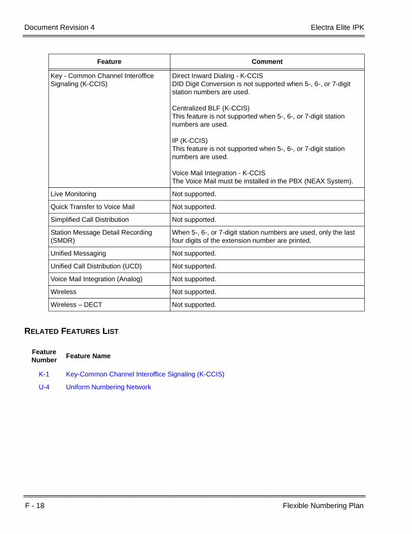
F - 18 Flexible Numbering Plan
___________________________________________________________________________________
___________________________________________________________________________________Document Revision 4 Electra Elite IPK
RELATED FEATURES LIST
Key - Common Channel Interoffice Signaling (K-CCIS)
Direct Inward Dialing - K-CCIS DID Digit Conversion is not supported when 5-, 6-, or 7-digit station numbers are used.
Centralized BLF (K-CCIS) This feature is not supported when 5-, 6-, or 7-digit station numbers are used.
IP (K-CCIS) This feature is not supported when 5-, 6-, or 7-digit station numbers are used.
Voice Mail Integration - K-CCISThe Voice Mail must be installed in the PBX (NEAX System).
Live Monitoring Not supported.
Quick Transfer to Voice Mail Not supported.
Simplified Call Distribution Not supported.
Station Message Detail Recording (SMDR)
When 5-, 6-, or 7-digit station numbers are used, only the last four digits of the extension number are printed.
Unified Messaging Not supported.
Unified Call Distribution (UCD) Not supported.
Voice Mail Integration (Analog) Not supported.
Wireless Not supported.
Wireless – DECT Not supported.
Feature Number
Feature Name
K-1 Key-Common Channel Interoffice Signaling (K-CCIS)
U-4 Uniform Numbering Network
Feature Comment
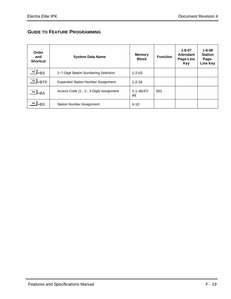
Electra Elite IPK Document Revision 4
Features and Specifications Manual F - 19
___________________________________________________________________________________
___________________________________________________________________________________
GUIDE TO FEATURE PROGRAMMING
Orderand
ShortcutSystem Data Name
Memory Block
Function
1-8-07AttendantPage-Line
Key
1-8-08StationPage-
Line Key
+BS 2~7-Digit Station Numbering Selection 1-2-03
+BTS Expanded Station Number Assignment 1-2-34
+BAAccess Code (1-, 2-, 3-Digit) Assignment 1-1-46/47/
48001
+BS Station Number Assignment 4-10

F - 20 Flexible Numbering Plan
___________________________________________________________________________________
___________________________________________________________________________________Document Revision 4 Electra Elite IPK
THIS PAGE INTENTIONALLY LEFT BLANK

Features and Specifications Manual F - 21
___________________________________________________________________________________
___________________________________________________________________________________
Flexible Ringing Assignment F-5
FEATURE DESCRIPTION
Flexible Ringing Assignments for incoming outside calls and Secondary Incoming Extension appearances can be programmed to ring at specified Multiline Terminals. Separate day and night ring assignments are available, and Delayed Ringing is an option for Multiline Terminals.
SYSTEM AVAILABILITY
Terminal Type:
All Stations
Required Components:
None
OPERATING PROCEDURES
None
SERVICE CONDITIONS
General:
Single Line Telephones can be assigned to ring for any line.
Single Line Telephones support Delayed Ringing.
Default values assign Attendants 1 and 2 (stations 100 and 101) to have CO/PBX lines 01~08 ringing.

F - 22 Flexible Ringing Assignment
___________________________________________________________________________________
___________________________________________________________________________________Document Revision 4 Electra Elite IPK
GUIDE TO FEATURE PROGRAMMING
Orderand
ShortcutSystem Data Name
Memory Block
Function
1-8-07AttendantPage-Line
Key
1-8-08StationPage-
Line Key
+BTM Line Key Selection for Telephone Mode 4-12
+BTT CO/PBX Ring Assignment (Day Mode) 4-01
+BTT CO/PBX Ring Assignment (Night Mode) 4-02
+BTTCO/PBX Answer Key Operation Without Ringing Assignment (Day Mode)
4-52
+BTTCO/PBX Answer Key Operation Without Ringing Assignment (Night Mode)
4-53
+BTMExtension Line Key Ring Assignment (Day Mode)
4-37
+BTMExtension Line Key Ring Assignment (Night Mode)
4-38
+BTP Doorphone Chime Assignment (Day Mode) 4-03
+BTP Doorphone Chime Assignment (Night Mode) 4-04
+BTSDistinctive Ring by Telephone or CO Selection
1-1-28
+BCT CO/PBX Ringing Variation Selection 3-07
+BTM Telephone Ringing Variation Selection 4-91
+BI Intercom Ring Pattern Selection 1-2-19
+BI Intercom Ring Tone Selection 1-2-20
+BTM Off-Hook Ringing Selection 4-51

Features and Specifications Manual F - 23
___________________________________________________________________________________
___________________________________________________________________________________
Flexible Timeouts F-6
FEATURE DESCRIPTION
The Flexible Timeouts feature provides a variety of over 40 timeouts in the Resident System Program to allow the system to operate without initial programming. The system timeouts can be changed to meet customer needs according to the system application requirements.
ENHANCEMENT(S)
Release 3000:
With R3000 or higher, the following timers are modified to allow assignment at 1-second intervals, and a Flexible Timeout Class of Service is added. Refer to the table below:
MemoryBlock
TitleTimeout
ClassDefault Minimum Maximum Comment
1-1-03Hold Recall Time Selection (Non-Exclusive Hold)
Yes 060s 001s 255s000s
(Infinity)
1-1-05 Start Time Selection Yes 02s 01s 99s00s
(Infinity)
1-1-06CO/PBX Incoming Ringing Alarm Time Selection
N/A000s
(Infinity)001s 255s
000s(Infinity)
1-1-07Tie Line Delay Ringing Time Selection
Yes000s
(Infinity)001s 255s
000s(Infinity)
1-1-12Transfer/Camp-On Recall Time Selection
Yes 060s 001s 999s000s
(Infinity)
1-1-37Trunk Queuing Timeout Selection
Yes 10s 01s 99s00s
(Infinity)
1-1-63Hold Recall Time Selection (Exclusive)
Yes 060s 001s 999s000s
(Infinity)
1-1-81 ISDN Dial Interval Selection N/A 04s 01s 99s
1-2-00Internal Paging Timeout Selection
Yes 090s 001s 255s000s
(Infinity)

F - 24 Flexible Timeouts
___________________________________________________________________________________
___________________________________________________________________________________Document Revision 4 Electra Elite IPK
SYSTEM AVAILABILITY
Terminal Type:
All Stations
Required Components:
None
OPERATING PROCEDURES
None
1-2-02Automatic Callback Release Time Selection
Yes 30m 01m 99m00s
(Infinity)
1-2-22Call forward – No Answer Time Selection
Yes 12s 01s 99s
1-2-23System Call Park Recall Time Selection
Yes 060s 001s 999s
1-3-03First Digit PBR Release Time Selection
N/A 10s 01s 99s
1-4-01Automated Attendant First Digit PBR Release Time Selection
N/A 20s 01s 99s
1-4-02Automated Attendant Transfer Delayed Ringing Time Selection
Yes00s
(Infinity)01s 99s
00s(Infinity)
1-4-03Automated Attendant No Answer Disconnect Time Selection
N/A 120s 001s 255s
1-7-01Doorphone Display Time Selection
N/A 10s 01s 99s
1-7-06External Paging Timeout Selection
Yes 300s 000s 999s000s
(Infinity)
This Memory Block is assigned in 1-minute intervals.
MemoryBlock
TitleTimeout
ClassDefault Minimum Maximum Comment
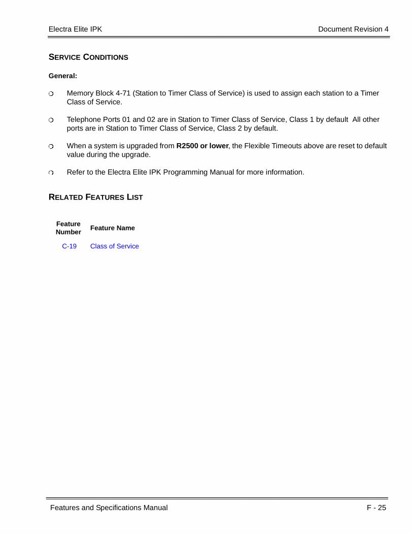
Electra Elite IPK Document Revision 4
Features and Specifications Manual F - 25
___________________________________________________________________________________
___________________________________________________________________________________
SERVICE CONDITIONS
General:
Memory Block 4-71 (Station to Timer Class of Service) is used to assign each station to a Timer Class of Service.
Telephone Ports 01 and 02 are in Station to Timer Class of Service, Class 1 by default All other ports are in Station to Timer Class of Service, Class 2 by default.
When a system is upgraded from R2500 or lower, the Flexible Timeouts above are reset to default value during the upgrade.
Refer to the Electra Elite IPK Programming Manual for more information.
RELATED FEATURES LIST
Feature Number
Feature Name
C-19 Class of Service

F - 26 Flexible Timeouts
___________________________________________________________________________________
___________________________________________________________________________________Document Revision 4 Electra Elite IPK
GUIDE TO FEATURE PROGRAMMING
Orderand
ShortcutSystem Data Name
Memory Block
Function
1-8-07Attendant
Page-Line Key
1-8-08StationPage-
Line Key
+AUAutomated Attendant Answer Delay Time Assignment
1-4-13
+AUAutomated Attendant First Digit PBR Release Time Selection
1-4-01
+AUAutomated Attendant No Answer Disconnect Time Selection
1-4-03
+AUAutomated Attendant Transfer Delayed Ringing Time Selection
1-4-02
+BCM CO/PBX Prepause Time Selection 1-1-57
+BCM DP Interdigit Time Selection 1-1-01
+BCM Hookflash Time Selection 1-1-02
+BCM Pause Time Selection 1-1-00
+BCTAutomatic Release Signal Detection Time Selection
3-40
+BCT Disconnect Recognition Time Selection 3-33
+BCT Trunk DTMF Duration/Interdigit Selection 3-15
+BCTTie Line CO/PBX Incoming Signal Detect Time Selection
3-19
+ARFirst Delay Announcement Start Time Selection
1-1-71
+ARFirst to Second Delay Announcement Interval Time Selection
1-1-73
+ARSecond Delay Announcement Repeat Interval Time Selection
1-1-75
+BP External Paging Timeout Selection 1-7-06
+BM Automatic Callback Release Time Selection 1-2-02
+BM Call Forward – No Answer Time Selection 1-2-22
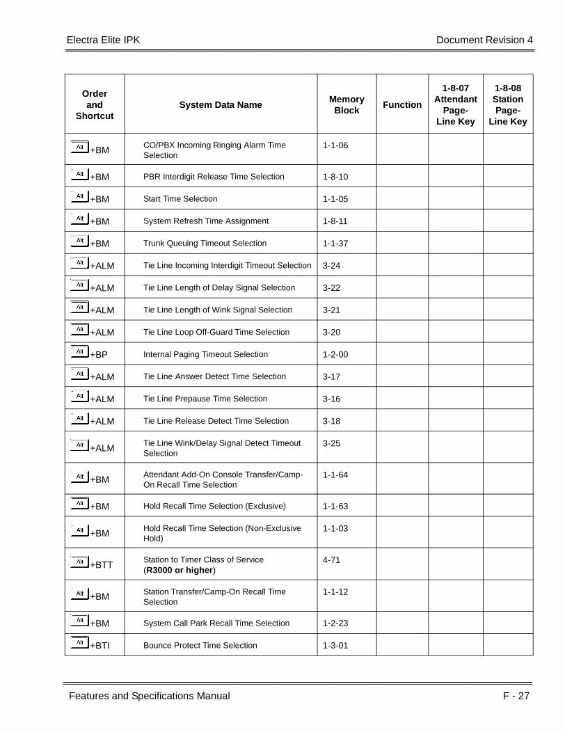
Electra Elite IPK Document Revision 4
Features and Specifications Manual F - 27
___________________________________________________________________________________
___________________________________________________________________________________
+BMCO/PBX Incoming Ringing Alarm Time Selection
1-1-06
+BM PBR Interdigit Release Time Selection 1-8-10
+BM Start Time Selection 1-1-05
+BM System Refresh Time Assignment 1-8-11
+BM Trunk Queuing Timeout Selection 1-1-37
+ALM Tie Line Incoming Interdigit Timeout Selection 3-24
+ALM Tie Line Length of Delay Signal Selection 3-22
+ALM Tie Line Length of Wink Signal Selection 3-21
+ALM Tie Line Loop Off-Guard Time Selection 3-20
+BP Internal Paging Timeout Selection 1-2-00
+ALM Tie Line Answer Detect Time Selection 3-17
+ALM Tie Line Prepause Time Selection 3-16
+ALM Tie Line Release Detect Time Selection 3-18
+ALMTie Line Wink/Delay Signal Detect Timeout Selection
3-25
+BMAttendant Add-On Console Transfer/Camp-On Recall Time Selection
1-1-64
+BM Hold Recall Time Selection (Exclusive) 1-1-63
+BMHold Recall Time Selection (Non-Exclusive Hold)
1-1-03
+BTTStation to Timer Class of Service(R3000 or higher)
4-71
+BM Station Transfer/Camp-On Recall Time Selection
1-1-12
+BM System Call Park Recall Time Selection 1-2-23
+BTI Bounce Protect Time Selection 1-3-01
Orderand
ShortcutSystem Data Name
Memory Block
Function
1-8-07Attendant
Page-Line Key
1-8-08StationPage-
Line Key

F - 28 Flexible Timeouts
___________________________________________________________________________________
___________________________________________________________________________________Document Revision 4 Electra Elite IPK
+BTI First Digit PBR Release Time Selection 1-3-03
+BTI Hookflash End Time Selection 1-3-06
+BTI Hookflash Start Time Selection 1-3-05
+AS SMDR Valid Call Time Assignment 1-5-25
+ALM Tie Line Delay Ringing Time Selection 1-1-07
+ATTandem Transfer Automatic Disconnect Time Selection
1-4-00
+AV Voice Mail Disconnect Time Selection 1-3-09
+AV Voice Mail DTMF Delay Time Selection 1-3-08
+AVVoice Mail DTMF Duration/Interdigit Time Selection
1-3-10
Orderand
ShortcutSystem Data Name
Memory Block
Function
1-8-07Attendant
Page-Line Key
1-8-08StationPage-
Line Key

Features and Specifications Manual F - 29
___________________________________________________________________________________
___________________________________________________________________________________
Full Duplex Handsfree F-7
FEATURE DESCRIPTION
The HF-R Unit is an add-on device to the Electra Elite IPK Multiline Terminals that provides a full duplex speakerphone for small conference rooms. An external microphone is also provided that has a locking push-to-mute control button to turn the microphone off.
SYSTEM AVAILABILITY
Terminal Type:
All Electra Elite IPK Multiline Terminals with an HF-R Unit installed
Required Software:
R1500 or higher
Required Components:
HF-R Unit
AC-R Unit (AC Adapter)
OPERATING PROCEDURES
To use the HF-R using an Electra Elite IPK Multiline Terminal:
1. Press E , and make an internal or external call.
2. When muting is desired, press the Mute key on the external microphone. To cancel muting, press the Mute button again.

F - 30 Full Duplex Handsfree
___________________________________________________________________________________
___________________________________________________________________________________Document Revision 4 Electra Elite IPK
SERVICE CONDITIONS
General:
This full-duplex unit does not work as well as a conference-room-type speakerphone. The echo cancellation works best in a smaller area (such as an office) with average acoustics. Large environment areas with hard surfaces that tend to bounce sound have an adverse affect on the speakerphone.
A full Duplex Handsfree Unit (HFU-U Unit) is also available for Electra Elite Multiline Terminals (DTU/DTP-( )-1 Telephones).
RELATED FEATURE LIST
GUIDE TO FEATURE PROGRAMMING
Feature Number
Feature Name
A-7 Ancillary Device Connection
E-2 Electra Elite IPK Terminals
E-3 Electra Elite Terminal Migration
Orderand
ShortcutSystem Data Name
Memory Block
Function
1-8-07AttendantPage-Line
Key
1-8-08StationPage-
Line Key
+BTM HFU Selection 4-29
When the system is at default this Memory Block must be programmed for the feature to be used.

Features and Specifications Manual F - 31
___________________________________________________________________________________
___________________________________________________________________________________
Full Handsfree Operation F-8
FEATURE DESCRIPTION
Built-in half-duplex handsfree operation is included with all Multiline Terminals for internal and external calls. The MIC ON/OFF key or Feature Access Code allows the microphone to be muted.
SYSTEM AVAILABILITY
Terminal Type:
All Multiline Terminals
Required Components:
None
OPERATING PROCEDURES
To turn the built-in Microphone ON/OFF:
1. Press A .
2. Dial A.
- OR -
Press the Flexible Line key assigned as a MIC ON/OFF key or One-Touch key programmed as a Microphone Control key or fixed MIC ON/OFF key on DTH/DTR Terminals.

F - 32 Full Handsfree Operation
___________________________________________________________________________________
___________________________________________________________________________________Document Revision 4 Electra Elite IPK
Using this feature with Multiline Terminal:
Originating:
1. Press E .
2. Dial the desired internal or outside number.
3. Talk with the party when the call is answered.
- OR -
1. Press the desired Feature Access or One-Touch key programmed for Speed Dial.
2. Talk with the party when the call is answered.
Answering:
1. Press the line key receiving an incoming call or press F .
2. Talk with the calling party.
SERVICE CONDITIONS
General:
One Override can be received during handsfree conversation.
The microphone must be ON to answer calls handsfree.
A Flexible Line key can be assigned as a MIC ON/OFF key, or a One-Touch key can be programmed as a Microphone Control key.
While engaged on an outside line conversation using built-in Handsfree Operation, the conversation may be interrupted (half-duplex) if both parties speak simultaneously.
During a conversation, the MIC ON/OFF key can be used to mute the microphone.
Monitoring volume can be adjusted using the volume control on the Multiline Terminal.
When a Multiline Terminal user lifts the handset, monitoring is automatically released, and the Speaker LED goes off.
The built-in Speakerphone is a half-duplex speaker phone. Noisy or poor acoustical environments have a large impact on the speaker phone switching from transmit to receive calls and vice versa.

Electra Elite IPK Document Revision 4
Features and Specifications Manual F - 33
___________________________________________________________________________________
___________________________________________________________________________________
RELATED FEATURES LIST
GUIDE TO FEATURE PROGRAMMING
Feature Number
Feature Name
A-7 Ancillary Device Connection
E-2 Electra Elite IPK Terminals
E-3 Electra Elite Terminal Migration
F-7 Full Duplex Handsfree
Orderand
ShortcutSystem Data Name
Memory Block
Function
1-8-07AttendantPage-Line
Key
1-8-08StationPage-
Line Key
+BTM HFU Selection 4-29
When the system is at default this Memory Block must be programmed for the feature to be used.

F - 34 Full Handsfree Operation
___________________________________________________________________________________
___________________________________________________________________________________Document Revision 4 Electra Elite IPK
THIS PAGE INTENTIONALLY LEFT BLANK

Features and Specifications Manual G - 1
___________________________________________________________________________________
___________________________________________________________________________________
General Purpose Relays G-1
FEATURE DESCRIPTION
Two relays are provided on the ECR-U( ) ETU to use as an application dictates. These relays are either off or on, and do not change state until a station user manually makes the change.
SYSTEM AVAILABILITY
Terminal Type:
All Multiline Terminals
Attendant Add-on Console
Required Components:
ECR-U( ) ETU
OPERATING PROCEDURES
To control the General Purpose Relay at the Attendant Add-On Console:
1. Press the key assigned GPR0 or GPR1.
2. The GPR LED is on (red) to indicate the relay is closed (on), or Off to indicate the relay is open (off).
To turn a General Purpose Relay on:
1. Press A and dialK.
2. Dial the relay numberK orA(for GPR0 or GPR1).
3. DialLand press A .

G - 2 General Purpose Relays
___________________________________________________________________________________
___________________________________________________________________________________Document Revision 4 Electra Elite IPK
To turn a General Purpose Relay off:
1. Press A and dialK.
2. Dial the relay numberK orA(for GPR0 or GPR1).
3. DialJand press A .
To toggle the relay from on to off (or off to on):
1. Press A and dialK.
2. Dial the relay numberK orA(for GPR0 or GPR1).
3. Press A .
SERVICE CONDITIONS
General:
The General Purpose relays are rated for 24 Vdc at 500 mA.
The red LED indication is provided to indicate on or off when the GPR Access Codes are assigned to a Feature Access key.
The LED indication is provided to all Feature Access keys and Attendant Add-on Consoles that are assigned to GP Relay 0 or GP Relay 1 functions.
Use Memory Block 2-08 (ECR Relay to Tenant Assignment) to specify Tenant Assignment for External Tone Ring/Night Chime function. Default is not assigned.
Use Memory Block 7-1 (Card Interface Slot Assignment) to specify the ECR-U( ) ETU.
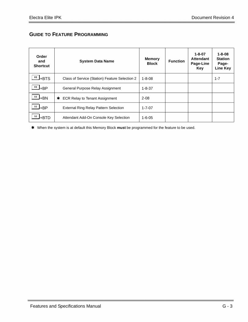
Electra Elite IPK Document Revision 4
Features and Specifications Manual G - 3
___________________________________________________________________________________
___________________________________________________________________________________
GUIDE TO FEATURE PROGRAMMING
Orderand
ShortcutSystem Data Name
Memory Block
Function
1-8-07AttendantPage-Line
Key
1-8-08StationPage-
Line Key
+BTS Class of Service (Station) Feature Selection 2 1-8-08 1-7
+BP General Purpose Relay Assignment 1-8-37
+BN ECR Relay to Tenant Assignment 2-08
+BP External Ring Relay Pattern Selection 1-7-07
+BTD Attendant Add-On Console Key Selection 1-6-05
When the system is at default this Memory Block must be programmed for the feature to be used.

G - 4 General Purpose Relays
___________________________________________________________________________________
___________________________________________________________________________________Document Revision 4 Electra Elite IPK
THIS PAGE INTENTIONALLY LEFT BLANK
Features and Specifications Manual G - 5
___________________________________________________________________________________
___________________________________________________________________________________
Ground Start Trunks G-2
FEATURE DESCRIPTION
Ground Start Trunks can be connected to the system. Assignment of trunks as Ground Start is per trunk (by switch settings) at the associated COI(8)-U( ) or COIB(4)-U10 ETU. Ground and Loop Start Trunks can be mixed in the system per trunk. Ground Start Trunks are provided with line supervision to reduce call collisions.
SYSTEM AVAILABILITY
Terminal Type:
Not applicable
Required Components:
COI(8)-U( ) or COIB(4)-U10 ETU to interface Ground Start Trunks to the system
OPERATING PROCEDURES
None
SERVICE CONDITIONS
General:
Each COI(8)-U( ) ETU has eight switches (one for each port) that can be used to select either Loop or Ground Start per trunk.
Each COIB(4)-U10 ETU has four switches (one for each port) that can be used to select either Loop or Ground Start per trunk.
When the serving CO sends a disconnect signal, after the outside party abandons a call, the trunk is automatically released.

G - 6 Ground Start Trunks
___________________________________________________________________________________
___________________________________________________________________________________Document Revision 4 Electra Elite IPK
Sixty-four trunks (Ground Start, Loop Start, E&M Tie Lines and DID Trunks) can be installed in the Electra Elite IPK system.
Each Multiline Terminal can have a Drop key assigned (when allowed in System Programming) to be used for abandoning a call and seizing the same CO line on either a Flexible Line or One-Touch key.
The Recall key can be used for a flexible timed hookflash when Least Cost Routing is installed.
Restrictions:
The following analog trunk interface cards do not support Ground Start Trunks COI(4)-U( ), COIB(4)-U20, and COIB(8)-U( ).
Ground Start Trunks do not support Caller ID.
GUIDE TO FEATURE PROGRAMMING
Orderand
ShortcutSystem Data Name
Memory Block
Function
1-8-07AttendantPage-Line
Key
1-8-08StationPage-
Line Key
+BS Card Interface Slot Assignment 7-1
Features and Specifications Manual G - 7
___________________________________________________________________________________
___________________________________________________________________________________
Group Listening G-3
FEATURE DESCRIPTION
Group Listening allows the user to press the Speaker key so others in the room can listen to a conversation over the built-in speaker of a Multiline Terminal. While Group Listening is active, the Multiline Terminal user can continue to talk on the handset or headset.
SYSTEM AVAILABILITY
Terminal Type:
All Multiline Terminals
Required Components:
None
OPERATING PROCEDURES
To activate/deactivate Group Listening:
1. While using the handset/headset, press E to activate Group Listening.
2. Press E or go on-hook to end Group Listening.
To mute the handset during Group Listening using Electra Elite Multiline Terminals (DTP/DTU-( )-( ) TEL):
When MIC LED is on, press A and Ato turn off the LED to mute the handset.

G - 8 Group Listening
___________________________________________________________________________________
___________________________________________________________________________________Document Revision 4 Electra Elite IPK
SERVICE CONDITIONS
General:
Group Listening applies to the following conditions:
During an internal call
During an outside call
During a conference call
During a Voice Over call
During a Whisper Page call
A feedback loop is possible when Group Listening is not canceled before the handset is placed in the cradle. The outside caller hears a feedback squeal. When switching to Handsfree Monitor Mode or Speakerphone Mode, mute the handset before placing it in the cradle.
When the user goes on-hook during Group Listening, the call is automatically placed in Handsfree Monitor/Speakerphone Mode and Group Listening is canceled.
Off-hook ringing is provided with this feature.
Camp-on tone and Tone Override are heard over the handset, headset, or speakerphone.
During Group Listening, speaker volume can be adjusted using the Multiline Terminal volume control. The handset volume cannot be adjusted.
During Group Listening, the user cannot use the built-in microphone for handsfree use. The MIC key is pressed to control handset mute and the MIC LED flashes red during handset mute mode.
GUIDE TO FEATURE PROGRAMMING
Orderand
ShortcutSystem Data Name
Memory Block
Function
1-8-07AttendantPage-Line
Key
1-8-08StationPage-
Line Key
+BTS Class of Service (Station) Feature Selection 2 1-8-08 5-2
+BTT Station to Class of Service Feature Assignment
4-17
When the system is at default this Memory Block must be programmed for the feature to be used.

Features and Specifications Manual H - 1
___________________________________________________________________________________
___________________________________________________________________________________
Handset Mute H-1
FEATURE DESCRIPTION
Handset Mute is provided to most terminals connected to the Electra Elite IPK system. While talking on the Multiline Terminal handset, a station user can dial a feature code or press the MIC button to mute the transmit speech path. The station user can still hear the outside (or intercom) voice.
SYSTEM AVAILABILITY
Terminal Type:
All Multiline Terminals
Required Components:
None
OPERATING PROCEDURES
While talking on a Terminal Handset:
Press I (DTH/DTR terminals only).
- OR -
Press A and dialA.
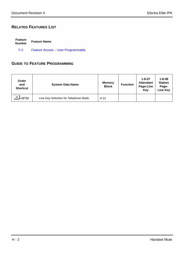
H - 2 Handset Mute
___________________________________________________________________________________
___________________________________________________________________________________Document Revision 4 Electra Elite IPK
RELATED FEATURES LIST
GUIDE TO FEATURE PROGRAMMING
Feature Number
Feature Name
F-2 Feature Access – User Programmable
Orderand
ShortcutSystem Data Name
Memory Block
Function
1-8-07AttendantPage-Line
Key
1-8-08StationPage-
Line Key
+BTM Line Key Selection for Telephone Mode 4-12
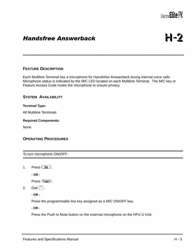
Features and Specifications Manual H - 3
___________________________________________________________________________________
___________________________________________________________________________________
Handsfree Answerback H-2
FEATURE DESCRIPTION
Each Multiline Terminal has a microphone for Handsfree Answerback during internal voice calls. Microphone status is indicated by the MIC LED located on each Multiline Terminal. The MIC key or Feature Access Code mutes the microphone to ensure privacy.
SYSTEM AVAILABILITY
Terminal Type:
All Multiline Terminals
Required Components:
None
OPERATING PROCEDURES
To turn microphone ON/OFF:
1. Press I .
- OR -
Press A .
2. DialA.
- OR -
Press the programmable line key assigned as a MIC ON/OFF key.
- OR -
Press the Push to Mute button on the external microphone on the HFU-U Unit.
H - 4 Handsfree Answerback
___________________________________________________________________________________
___________________________________________________________________________________Document Revision 4 Electra Elite IPK
To use this feature when receiving an internal voice call:
1. Ensure MIC LED is on.
2. Talk with calling party.
SERVICE CONDITIONS
General:
Multiline Terminal MIC LED must be on.
The calling station controls the voice announcement or ringing signal.
Multiline Terminal users can receive voice calls from Single Line Telephone users.
Group Call Pickup and Call Forwarding do not operate for voice announcement calls.
Restrictions:
When a station is signaled by a tone signal, the station user cannot respond with Handsfree Answerback, unless the calling party changes to voice call.
This feature works only for incoming internal voice calls.
RELATED FEATURES LIST
Feature Number
Feature Name
I-5 Internal Voice/Tone Signaling

Electra Elite IPK Document Revision 4
Features and Specifications Manual H - 5
___________________________________________________________________________________
___________________________________________________________________________________
GUIDE TO FEATURE PROGRAMMING
Orderand
ShortcutSystem Data Name
Memory Block
Function
1-8-07AttendantPage-Line
Key
1-8-08StationPage-
Line Key
+BI Intercom Call Voice/Tone Signal Selection 1-2-01
+BTD DSS Call Voice/Tone Signal Selection 1-6-03
+BA Intercom Feature access Code Assignment 1-2-24 001
+BN Line Key Selection 2-05
+BN Line Key Selection for Tenant Mode 2-06
+BTM Line Key Selection for Telephone Mode 4-12
H - 6 Handsfree Answerback
___________________________________________________________________________________
___________________________________________________________________________________Document Revision 4 Electra Elite IPK
THIS PAGE INTENTIONALLY LEFT BLANK
Features and Specifications Manual H - 7
___________________________________________________________________________________
___________________________________________________________________________________
Handsfree Dialing and Monitoring H-3
FEATURE DESCRIPTION
Handsfree Dialing and Monitoring enables all Multiline Terminal users to dial and monitor calls without using the handset. This feature frees the user to perform other tasks while waiting for a call to be answered or while on hold.
SYSTEM AVAILABILITY
Terminal Type:
All Multiline Terminals
Required Components:
None
OPERATING PROCEDURES
To use handsfree dialing:
1. Press E .
2. Use any dialing method allowed by the system.
3. When the party answers, talk using the handset or built-in Handsfree Unit if enabled.
4. When there is no answer or busy tone is received, press E to disconnect the line.
To use monitoring with a call in progress:
1. Press E .
2. Restore the handset.

H - 8 Handsfree Dialing and Monitoring
___________________________________________________________________________________
___________________________________________________________________________________Document Revision 4 Electra Elite IPK
SERVICE CONDITIONS
General:
A Multiline Terminal is considered off-hook by the system when this feature is used.
This feature may be used for internal and outside calls.
Monitoring volume may be adjusted using the volume control on the Multiline Terminal.
When a Multiline Terminal user lifts the handset, the monitoring condition is automatically released, and the Speaker LED goes off.
The Multiline Terminal must remain in monitor mode when Automatic Redial is being used.
Restrictions:
This feature is available only on Multiline Terminals.
RELATED FEATURES LIST
Feature Number
Feature Name
A-24 Automatic Redial
Features and Specifications Manual H - 9
___________________________________________________________________________________
___________________________________________________________________________________
Headset Connection (Built-In) H-4
FEATURE DESCRIPTION
A headset can be connected directly to an Electra Elite IPK Multiline Terminal. This eliminates the need for an external headset switch. A headset ON/OFF key can be assigned to the terminal to allow easy operation of the headset.
SYSTEM AVAILABILITY
Terminal Type:
All Multiline Terminals
Required Components:
Headset
OPERATING PROCEDURES
To make a call:
1. Press the headset ON/OFF key.
2. Dial the desired number and talk.
To end a call:
1. At the end of a conversation, press the headset ON/OFF key.
2. Call is disconnected.
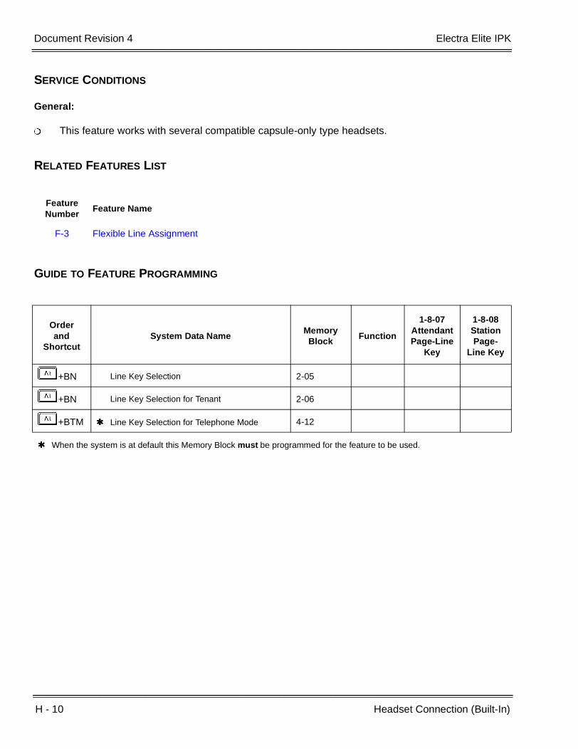
H - 10 Headset Connection (Built-In)
___________________________________________________________________________________
___________________________________________________________________________________Document Revision 4 Electra Elite IPK
SERVICE CONDITIONS
General:
This feature works with several compatible capsule-only type headsets.
RELATED FEATURES LIST
GUIDE TO FEATURE PROGRAMMING
Feature Number
Feature Name
F-3 Flexible Line Assignment
Orderand
ShortcutSystem Data Name
Memory Block
Function
1-8-07AttendantPage-Line
Key
1-8-08StationPage-
Line Key
+BN Line Key Selection 2-05
+BN Line Key Selection for Tenant 2-06
+BTM Line Key Selection for Telephone Mode 4-12
When the system is at default this Memory Block must be programmed for the feature to be used.
Features and Specifications Manual H - 11
___________________________________________________________________________________
___________________________________________________________________________________
Hold With Recall (Exclusive
and Non-Exclusive) H-5
FEATURE DESCRIPTION
A station user can place a call on Hold to free the station for other calls. A Multiline Terminal user can use Exclusive Hold (call picked up only where it was put on hold) or Non-Exclusive Hold (call picked up at any station that has access to that line). A Single Line Telephone user can place calls on Exclusive Hold. A call on hold for longer than a programmed interval generates a recall at the originating station. When the recalled Multiline Terminal is idle, an audible signal and an LCD indication (when equipped) are provided to indicate that the line is recalling.
SYSTEM AVAILABILITY
Terminal Type:
All Multiline Terminals (Both Exclusive and Non-Exclusive Hold)
All Single Line Telephones (Exclusive Hold)
Required Components:
None
OPERATING PROCEDURES
Using a Multiline Terminal with an outside call in progress (Non-Exclusive Hold):
1. Press H .
2. To retrieve a Non-Exclusive Hold call, press the flashing line key or Call Appearance Key.
Using a Multiline Terminal with an outside call in progress (Exclusive Hold):
1. Press A and then H .
2. To retrieve an Exclusive Hold call, press the flashing line key or Call Appearance Key.

H - 12 Hold With Recall (Exclusive and Non-Exclusive)
___________________________________________________________________________________
___________________________________________________________________________________Document Revision 4 Electra Elite IPK
Using a Single Line Telephone with a call in progress:
1. Momentarily press the hookswitch; the call is placed on Exclusive Hold. When the handset is returned to the cradle, the call recalls immediately.
2. To retrieve a held call, momentarily press the hookswitch; the held call is connected.
- OR -
To retrieve a held call, return the handset to the cradle.
3. When recall begins, lift the handset and the call is connected.
SERVICE CONDITIONS
Multiline Terminal
Non-Exclusive Hold
After Non-Exclusive Hold is set, the user can originate or answer other calls.
Any station with the same outside line or programmed Call Appearance key can pick up the held call.
A CO/PBX call on Non-Exclusive Hold can be picked up by dialing an Access Code (Specified Line Seizure) when assigned in System Programming.
Use Memory Block 1-1-03 [Hold Recall Time Selection (Non-Exclusive Hold)] to specify the time (default: 25 seconds) that the call is held or parked before it recalls to the station where the call was placed on Hold.
The station where the Hold originated receives an I-Hold indication (flashing green LED). The LED associated with the held line key flashes red on all other Multiline Terminals.
Exclusive Hold
After Exclusive Hold is set, the user can originate or answer other calls.
When assigned, a call is held on a CO line key appearance. When not assigned, the call is exclusively held on a Call Appearance key.
Only at the station where the Exclusive Hold was set can a user retrieve the held call, until the call recalls.
Use Memory Block 1-1-63 [Hold Recall Time Selection (Exclusive)] to specify the time (default: 1 minute) that the call is held or parked before it recalls to the station where the call was placed on Hold.
Electra Elite IPK Document Revision 4
Features and Specifications Manual H - 13
___________________________________________________________________________________
___________________________________________________________________________________
The LED of other Multiline Terminals for the held line have a red LED on until the call recalls.
Exclusive Hold and Non-Exclusive Hold Recall time intervals can be adjusted independently of one another.
Hold Recall
Use Memory Block 4-30 (Hold Transfer Recall Display Selection), to enable (default: YS) or disable (NO) the Hold Recall indication on the LCD.
When a held line recalls, Multiline Terminals equipped with an LCD receive the following information: the upper LCD line shows the recalling outside line number, the lower LCD line shows the station number the call was held at and the station number where the call was transferred (used for recalling Ring Transfer or Camp-On calls).
Non-Exclusive Hold, Ring Transfer, Hold Recall, Call Park System, and Attendant Ring Transfer/Camp-On have separate Recall Timers.
For Multiline Terminals, internally held calls do not recall.
A Recall Tone is provided when the handset is on-hook. Off-hook ringing is not provided if the handset is off-hook.
Single Line Telephone
When the user goes on-hook during Exclusive Hold, recall immediately follows.
When a line is holding on a Multiline Terminal, the red LED is on until the Exclusive Hold Recall Time expires.
The System Call Park feature can be used to put calls on hold.
Restrictions:
Only the first 13 digits of a 16-character name are displayed while a Hold Recall is recalling to a Display Terminal (R4000 or higher).
RELATED FEATURES LIST
Feature Number
Feature Name
I-1 I-Hold Indication
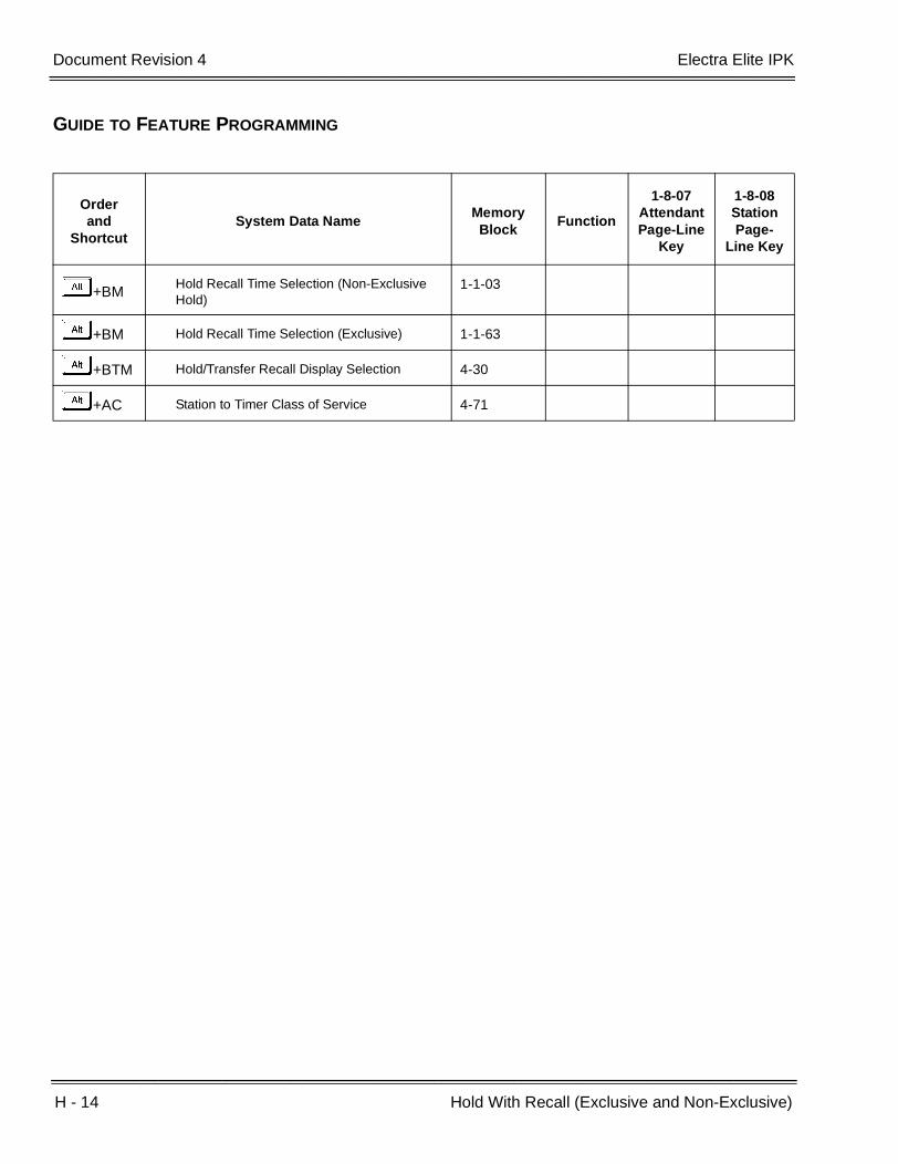
H - 14 Hold With Recall (Exclusive and Non-Exclusive)
___________________________________________________________________________________
___________________________________________________________________________________Document Revision 4 Electra Elite IPK
GUIDE TO FEATURE PROGRAMMING
Orderand
ShortcutSystem Data Name
Memory Block
Function
1-8-07AttendantPage-Line
Key
1-8-08StationPage-
Line Key
+BMHold Recall Time Selection (Non-Exclusive Hold)
1-1-03
+BM Hold Recall Time Selection (Exclusive) 1-1-63
+BTM Hold/Transfer Recall Display Selection 4-30
+AC Station to Timer Class of Service 4-71

Features and Specifications Manual H - 15
___________________________________________________________________________________
___________________________________________________________________________________
Hot Key Pad H-6
FEATURE DESCRIPTION
This feature allows Multiline Terminals to make an outgoing or internal call by pressing digits on the Dial Pad of the Multiline Terminal without pressing the Speaker key or Trunk Key before going off-hook.
R4000 or higher is required to support this feature.
SYSTEM AVAILABILITY
Terminal Type:
All Multiline Terminals
Required Components:
None
OPERATING PROCEDURES
From Multiline Terminal:
1. Dial the desired digits on the dial pad.
2. Converse when dialed party answers.
SERVICE CONDITIONS
General:
Hot Key Pad has priority over Preset Dialing when both features are allowed in the same class of service.
LCR and ARS can be used with Hot Key Pad when placing outside calls.

H - 16 Hot Key Pad
___________________________________________________________________________________
___________________________________________________________________________________Document Revision 4 Electra Elite IPK
This feature uses the system assigned access codes to determine if the call is internal or outside.
RELATED FEATURES LIST
GUIDE TO FEATURE PROGRAMMING
Feature Number
Feature Name
C-19 Class of Service
P-4 Preset Dialing
P-5 Prime Line Assignment
Orderand
ShortcutSystem Data Name
Memory Block
Function
1-8-07AttendantPage-Line
Key
1-8-08StationPage-
Line Key
+BTS Class of Service (Station) Feature Selection 2 1-8-08 7,4

Features and Specifications Manual H - 17
___________________________________________________________________________________
___________________________________________________________________________________
Hot Line H-7
FEATURE DESCRIPTION
Hot Line enables a station user to go off-hook to automatically dial an outside number or another station. This feature is provided for Multiline Terminals and Single Line Telephones.
SYSTEM AVAILABILITY
Terminal Type:
All Stations
Required Components:
None
OPERATING PROCEDURES
To execute at any station programmed for Hot Line:
1. Lift the handset to go off-hook, or press E .
2. The station or outside number is called.
SERVICE CONDITIONS
General:
Only hardware abilities limit the number of Hot Lines that can be supported in the system.
Up to 10 digits can be stored for dialing, including Trunk Access Codes.
Multiline Terminal users assigned Hot Line can press the Feature key and Access Code 6 or press Feature + Speaker to receive internal dial tone.

H - 18 Hot Line
___________________________________________________________________________________
___________________________________________________________________________________Document Revision 4 Electra Elite IPK
With Hot Line assigned, internal dial tone can be received by pressing the Hold, Conference, or Transfer key while on call.
RELATED FEATURES LIST
GUIDE TO FEATURE PROGRAMMING
Feature Number
Feature Name
F-2 Feature Access – User Programmable
Orderand
ShortcutSystem Data Name
Memory Block
Function
1-8-07AttendantPage-Line
Key
1-8-08StationPage-
Line Key
+BA
Access Code (1-, 2-, or 3-Digit) Assignment 1-1-46/47/48
001101~ 132,176~199,201~232,401~416
+BTT Prime Line/Hot Line Assignment 4-23
When the system is at default this Memory Block must be programmed for the feature to be used.
Features and Specifications Manual H - 19
___________________________________________________________________________________
___________________________________________________________________________________
Howler Tone Service H-8
FEATURE DESCRIPTION
Howler Tone Service provides a Howler Tone when a station remains off-hook after a call is completed or when a station is off-hook and digits are not dialed in a programmed time.
SYSTEM AVAILABILITY
Terminal Type:
All Stations
Required Components:
None
OPERATING PROCEDURES
None
SERVICE CONDITIONS
General:
Howler tone is generated 30 seconds after a call is disconnected and the telephone is left off-hook or the telephone is left off-hook without dialing.
The Howler tone is continuously modulating at 2400 Hz and 16 Hz, by system default. This cycle can be programmed.

H - 20 Howler Tone Service
___________________________________________________________________________________
___________________________________________________________________________________Document Revision 4 Electra Elite IPK
GUIDE TO FEATURE PROGRAMMING
Orderand
ShortcutSystem Data Name
Memory Block
Function
1-8-07AttendantPage-Line
Key
1-8-08StationPage-
Line Key
+BI Tone Assignment 1-8-15

Features and Specifications Manual I - 1
___________________________________________________________________________________
___________________________________________________________________________________
I-Hold Indication I-1
Feature DESCRIPTION
I-Hold Indication provides a flashing green LED line key indication for external calls held at a Multiline Terminal. Calls held at other stations provide a flashing red LED line key indication. This feature allows easy identification of calls the user placed on hold.
SYSTEM AVAILABILITY
Terminal Type:
All Multiline Terminals
Required Components:
None
OPERATING PROCEDURES
To place a call on Hold:
Press H (the call is placed on Non-Exclusive Hold).
- OR -
Press A , and then H (the call is placed on Exclusive Hold).

I - 2 I-Hold Indication
___________________________________________________________________________________
___________________________________________________________________________________Document Revision 4 Electra Elite IPK
SERVICE CONDITIONS
The I-Hold and other hold-flash rates are the same, 0.25 seconds ON/0.25 seconds OFF.
When a call is placed on Exclusive Hold, all other Multiline Terminals with that line appearance receive a busy indication (steady red LED).
Internal calls can be put on Exclusive Hold only.
Answer Hold, Transfer Hold, and Conference Hold use the I-Hold indication.
RELATED FEATURES LIST
GUIDE TO FEATURE PROGRAMMING
Feature Number
Feature Name
H-5 Hold With Recall (Exclusive and Non-Exclusive)
Orderand
ShortcutSystem Data Name
Memory Block
Function
1-8-07AttendantPage-Line
Key
1-8-08StationPage-
Line Key
+BMHold Recall Time Selection (Non-Exclusive Hold)
1-1-03
+BM Hold Recall Time Selection (Exclusive) 1-1-63
+BMStation Transfer/Camp-On Recall Time Selection
1-1-12
+AC Station to Timer Class of Service 4-71
Features and Specifications Manual I - 3
___________________________________________________________________________________
___________________________________________________________________________________
Incoming Call Identification I-2
FEATURE DESCRIPTION
Incoming Call Identification (provided for Internal Ring Transfer, Call Forward, and CO Transfer Ring) displays caller name or station number on Multiline Terminals with an LCD. Internal calls are identified by caller name and station number. A ringing Tie line/DID call generates a display on the LCD of the line number. When Caller ID is provided, the CO incoming caller directory number or name is displayed. System software allows both name and number to be displayed by Caller ID.
SYSTEM AVAILABILITY
Terminal Type:
All Multiline Terminals with LCD
Required Components:
None
OPERATING PROCEDURES
For an incoming internal call:
1. The ICM LED flashes.
2. The caller station number and name (when assigned) are displayed on the LCD.
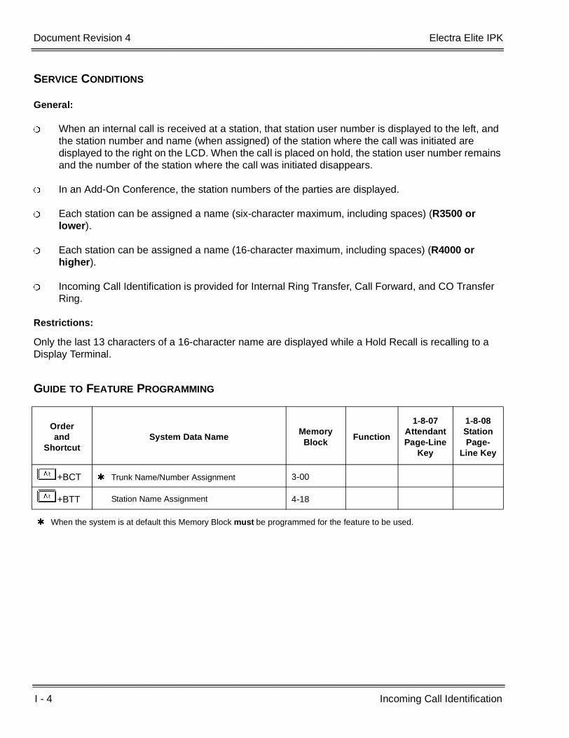
I - 4 Incoming Call Identification
___________________________________________________________________________________
___________________________________________________________________________________Document Revision 4 Electra Elite IPK
SERVICE CONDITIONS
General:
When an internal call is received at a station, that station user number is displayed to the left, and the station number and name (when assigned) of the station where the call was initiated are displayed to the right on the LCD. When the call is placed on hold, the station user number remains and the number of the station where the call was initiated disappears.
In an Add-On Conference, the station numbers of the parties are displayed.
Each station can be assigned a name (six-character maximum, including spaces) (R3500 or lower).
Each station can be assigned a name (16-character maximum, including spaces) (R4000 or higher).
Incoming Call Identification is provided for Internal Ring Transfer, Call Forward, and CO Transfer Ring.
Restrictions:
Only the last 13 characters of a 16-character name are displayed while a Hold Recall is recalling to a Display Terminal.
GUIDE TO FEATURE PROGRAMMING
Orderand
ShortcutSystem Data Name
Memory Block
Function
1-8-07AttendantPage-Line
Key
1-8-08StationPage-
Line Key
+BCT Trunk Name/Number Assignment 3-00
+BTT Station Name Assignment 4-18
When the system is at default this Memory Block must be programmed for the feature to be used.

Features and Specifications Manual I - 5
___________________________________________________________________________________
___________________________________________________________________________________
Incoming Trunk Name or Number Display I-3
FEATURE DESCRIPTION
Incoming Trunk Name or Number Display allows names or numbers to be assigned to each trunk of the system. These names or numbers appear on the Multiline Terminal LCD when receiving an incoming call.
SYSTEM AVAILABILITY
Terminal Type:
Any Multiline Terminal with LCD
Any TAPI Terminal
Required Components:
None
OPERATING PROCEDURES
None
SERVICE CONDITIONS
General:
Each CO/PBX trunk can have a name (13 character-maximum, including spaces) or number assigned.
This display function is valid for general incoming CO/PBX calls.
A maximum of 13 digits or characters can be displayed.
When a Caller ID CO call is terminated to a trunk assigned trunk name/number, the trunk name/number is displayed. In this case, the Caller ID data is not stored.
When an ACD/SCD/UCD call is received, the trunk name/number is displayed when assigned.
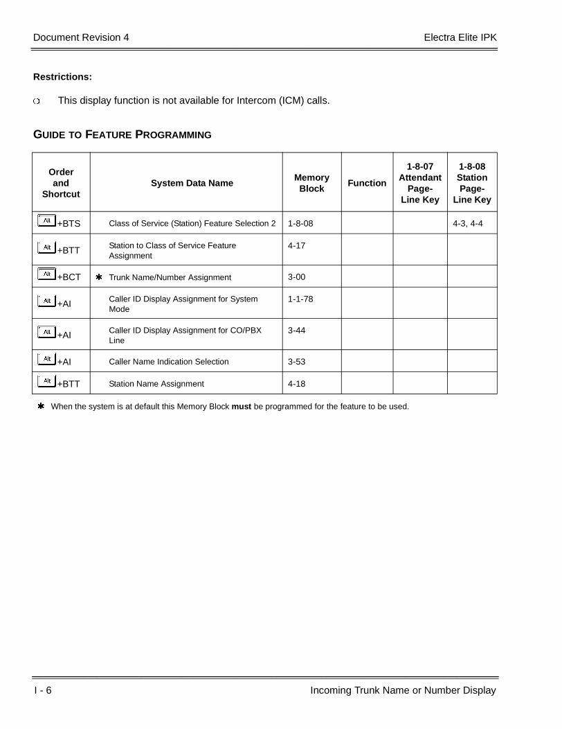
I - 6 Incoming Trunk Name or Number Display
___________________________________________________________________________________
___________________________________________________________________________________Document Revision 4 Electra Elite IPK
Restrictions:
This display function is not available for Intercom (ICM) calls.
GUIDE TO FEATURE PROGRAMMING
Orderand
ShortcutSystem Data Name
Memory Block
Function
1-8-07Attendant
Page-Line Key
1-8-08StationPage-
Line Key
+BTS Class of Service (Station) Feature Selection 2 1-8-08 4-3, 4-4
+BTT Station to Class of Service Feature Assignment
4-17
+BCT Trunk Name/Number Assignment 3-00
+AI Caller ID Display Assignment for System Mode
1-1-78
+AI Caller ID Display Assignment for CO/PBX Line
3-44
+AI Caller Name Indication Selection 3-53
+BTT Station Name Assignment 4-18
When the system is at default this Memory Block must be programmed for the feature to be used.

Features and Specifications Manual I - 7
___________________________________________________________________________________
___________________________________________________________________________________
Internal Hub I-4
FEATURE DESCRIPTION
In data communications, a hub is a place of convergence where data arrives from one or more directions and is forwarded out in one or more other directions. A hub may include a data switch (a product called a switch could usually be considered a hub as well). The hub is where data comes together using individual Ethernet ports, and the switch determines how and to which port the data is forwarded. When multiple ETUs requiring Ethernet data connections are installed in an Electra Elite IPK KSU, the HUB ETU can provide a neat and simple installation.
System Software R1500 or higher is required.
The HUB(8)-U( ) ETU is an in-skin, fast Ethernet switching HUB unit that provides the following services:
Auto Negotiation for Port Configurations
This feature can allow/deny Auto Negotiation for port speed and duplex mode for each port. When this function is allowed, the HUB(8)-U( ) ETU negotiates with linked equipment to determine the speed (10Mbps or 100Mbps) and operating duplex mode (Full or Half).
Port Speed Selection
Data switching speed can be manually set to 10Mbps or 100Mbps for each port. This feature is allowed only when Auto Negotiation is denied.
Duplex Mode Selection
Duplex mode can be manually set to Half Duplex or Full Duplex for each port. This feature is allowed only when Auto Negotiation function is denied.
MDI/MDIX Mode Selection
MDI/MDIX mode can be set to MDI, MDIX or Auto detection. When this mode is set to Auto detection, the HUB(8)-U( ) ETU can automatically determine whether or not it needs to cross over between pairs so that an external cross over cable is not required. If Auto Negotiation for port configuration is not allowed, this Auto MDIX mode must not be used. Only fixed MDI or MDIX mode can be used.
I - 8 Internal Hub
___________________________________________________________________________________
___________________________________________________________________________________Document Revision 4 Electra Elite IPK
Port Mirroring
The HUB-U( ) ETU is an 8-port switching HUB. One port can be set as a source port and one port can be set as a target port for port mirroring to monitor data traffic. The data on the Source port can then be monitored on the mirror port (target port). When VLAN tagging is configured, the source and target ports must be in the same VLAN(s).
VLAN Tagging
A Virtual LAN (VLAN) subdivides a local area network by logical, rather than physical or geographical, means.
For example, voice traffic can be put on one VLAN, and data traffic can be put on another VLAN. Ports on the same switching hub assigned to different VLANs are logically separated, and a router is required to pass traffic from one VLAN to another. A router would be put on a port configured to allow traffic from multiple VLANs. Using the Quality of Service (QoS) related memory blocks, the VLAN carrying voice traffic could be assigned a higher priority than VLANs carrying data traffic.
The HUB(8)-U( ) ETU supports the IEEE 802.1q standard for VLAN tagging for up to 16 VLAN Groups.
Flow Control
The HUB(8)-U( ) ETU supports two methods of flow control that are configured per port. For congestion on a full-duplex port, the ETU supports IEEE 802.3x flow control that allows a device to momentarily stop the flow of traffic from a transmitting device, by sending a pause frame.
For congestion on a half-duplex port, back pressure flow control is supported. Back pressure generates collision-detection signals in the CSMA/CD MAC-layer (media access control) protocol of Ethernet when a port is overloaded. These collision-detection signals from the congested port trick the sending port into believing a collision is imminent, and cause it to back off. This, in turn, forces a throttling back of the LAN segments experiencing congestion. When the sending ports try to transmit after the standard Ethernet delay time, the congested port may again send collision-detection signals or accept the incoming frames if ready.
QoS
The HUB-U( ) ETU has two priority assignment methods. One is Port-based Priority (frame received) and the other is IEEE 802.1q/p Tag-based Priority. Unknown Unicast Frames have a fixed low priority.
The Port based Priority feature can assign the priority for all frames except the Unknown Unicast Frames:
When set to High, the switching priority of a received frame on the port is always assigned as High.
When set to Low, the priority of a received frame is always assigned as Low.
When Not Assigned (set to No), this feature is disabled.
The Tag based Priority is allowed only when the HUB(8)-U( ) ETU is set as Tag VLAN mode, and Port-based Priority Assignment is denied.

Electra Elite IPK Document Revision 4
Features and Specifications Manual I - 9
___________________________________________________________________________________
___________________________________________________________________________________
Priority Assignment For Received Frame
Memory Block 1-16-07 (High Priority RX Tag Threshold) selects which priority field value is assigned as High. When a received frame contains a tag (per IEEE 802.1q definition), the HUB(8)-U( ) ETU can assign the priority (0~7) as High for the frame based on this assignment.
Frames with the highest priority are processed from the receive queue prior to any other priority frames.
Transmit Tag Priority Assignment
When the HUB-U( ) ETU transmits a frame in VLAN mode, the priority field value can be assigned for each untagged frame that is transmitted by the following assignments.
Memory block 1-16-08 (High Priority TX Tag Assignment) assigns the priority field value for frames that are High priority.
Memory block 1-16-09 (Low Priority TX Tag assignment) assigns the priority field value for frames that are Low priority.
This feature can be assigned for each port. Frames tagged the highest priority are sent from the transmit queue prior to any other priority frames.
Tag Mode Switching
The HUB(8)-U( ) ETU provides Tag-based VLAN implementation. Each arriving frame to theswitching hub is tagged by the sender as belonging to a VLAN. When VLAN Memory Blocks(4, 5, 13, 14, 15) are programmed with the Tagging information, the Hub(8)-U( ) providessupport for Tag-based VLAN. Behavior of the HUB(8)-U( ) ETU for frames belonging to aVLAN is described below.
When the Destination is a Unicast address and the entry was found in the Address table, theHUB(8)-U( ) ETU acts as follows:
When the Port Number is the same as the Port number on which the frame was received, the frame is discarded. (It is first received and checked for errors to update RMON counters).
When the Port Number is different, the frame is forwarded to the applicable local port. The tag is stripped or added according to the T field in the Address table entry. The tag is overwritten when the received frame is Priority tagged (i.e. Vid=0 in the tag) when forwarding on a tagged port.
When the Destination is a Unicast address and it is Unknown, the HUB(8)-U( ) ETU uses the Vid of the frame (either from frame tag or default of input port) to index to the VLAN table and forwards the frame to all ports (except source port) that are members of this VLAN. The tag is stripped or added according to the System data. The tag is overwritten when the received frame is Priority tagged (i.e. Vid=0 in the tag) when forwarding on a tagged port.
When the Destination is a Multicast address and the address entry is found, the HUB(8)-U( ) ETU uses the Vid to index into the VLAN table to retrieve the local ports that this frame should be forwarded to. Again, the tag may be removed added or changed by setting of the system data.
I - 10 Internal Hub
___________________________________________________________________________________
___________________________________________________________________________________Document Revision 4 Electra Elite IPK
SYSTEM AVAILABILITY
Terminal Type:
Not applicable
Required Components:
HUB(8)-U( ) ETU
OPERATING PROCEDURES
None
SERVICE CONDITIONS
General:
When Auto Negotiation is denied and port speed is set to 100Mbps, the yellow LED located on RJ45 connector is On. When port speed is set to 10Mbps, this LED is off.
Restrictions:
Only one HUB(8)-U( ) ETU can be assigned and installed per cabinet.
RELATED FEATURES LIST
Feature Number
Feature Name
C-24 Computer Telephony Integration (CTI)
V-3 Voice Over Internet Protocol (VoIP) Trunk Card

Electra Elite IPK Document Revision 4
Features and Specifications Manual I - 11
___________________________________________________________________________________
___________________________________________________________________________________
GUIDE TO FEATURE PROGRAMMING
Orderand
ShortcutSystem Data Name
Memory Block
Function
1-8-07Attendant
Page-Line Key
1-8-08StationPage-
Line Key
+BS Card Interface Slot Assignment 7-1
+AB Auto Negotiation Yes/No Selection 1-16-00
+AB Port Speed Selection - 10/100 Base-T 1-16-01
+AB Port Duplex Mode Selection 1-16-02
+AB MDI/MDIX Mode Selection 1-16-03
+AB VLAN Mode Selection 1-16-04
+AB Default VLAN ID Tag Insertion Assignment 1-16-05
+AB Port Based Priority Selection 1-16-06
+AB High Priority RX Tag Threshold 1-16-07
+AB High Priority TX Tag Assignment 1-16-08
+AB Low Priority TX Tag Assignment 1-16-09
+AB Port Mirroring Selection 1-16-10
+AB Mirroring Source Port Assignment 1-16-11
+AB Mirroring Target Port Assignment 1-16-12
+AB VLAN Group to VLAN ID Assignment 1-16-13
+AB Port VLAN Group Membership 1-16-14
+AB VLAN Tag Insertion Selection 1-16-15
+AB Flow Control for Full Duplex Selection 1-16-16
+AB Back Pressure for Half Duplex Selection 1-16-17

I - 12 Internal Hub
___________________________________________________________________________________
___________________________________________________________________________________Document Revision 4 Electra Elite IPK
THIS PAGE INTENTIONALLY LEFT BLANK

Features and Specifications Manual I - 13
___________________________________________________________________________________
___________________________________________________________________________________
Internal Voice/Tone Signaling I-5
FEATURE DESCRIPTION
Internal Voice/Tone Signaling allows a Multiline Terminal user to be signaled on incoming internal calls by voice announcement or by ringing, depending on System Programming. The caller can dial an additional digit to switch a voice announcement call to a ringing call, or switch a ringing call to voice announcement. This feature allows Voice/Tone switching from the calling side only.
SYSTEM AVAILABILITY
Terminal Type:
All Stations
Required Components:
None
OPERATING PROCEDURES
When programmed for Voice/Tone:
1. Lift the handset, and wait for internal dial tone.
2. Dial the station number.
3. Receive voice page alert tone.
4. Voice announce the call.
5. Called party can reply handsfree.
- OR -
Dial A(set as default). (Called party lifts the handset to respond to ringing.)

I - 14 Internal Voice/Tone Signaling
___________________________________________________________________________________
___________________________________________________________________________________Document Revision 4 Electra Elite IPK
When programmed for Tone/Voice:
1. Lift the handset, and wait for internal dial tone.
2. Dial the station number. (Called party station rings.)
3. Talk with party after the call is answered.
- OR -
Dial A (set as default).
4. Voice announce the call.
5. Called party can reply handsfree.
SERVICE CONDITIONS
General:
Voice or Tone can be selected as often as needed by dialing 1 (default) during a call.
When the station is receiving a handsfree call, the MIC must be activated for reply.
A Single Line Telephone user can switch from voice to tone or from tone to voice by dialing 1 (default) during an internal call to a Multiline Terminal.
When a voice announcement is received at a Multiline Terminal, other audible signals cannot be received.
When the Intercom (ICM) key is pressed during a normal incoming CO/PBX call, intercom dial tone is provided to allow an internal call.
The incoming call is answered when the Intercom (ICM) key is pressed.
Restrictions:
Single Line Telephone users can voice announce to Multiline Terminal users but cannot receive voice announcements.

Electra Elite IPK Document Revision 4
Features and Specifications Manual I - 15
___________________________________________________________________________________
___________________________________________________________________________________
GUIDE TO FEATURE PROGRAMMING
Orderand
ShortcutSystem Data Name
Memory Block
Function
1-8-07AttendantPage-Line
Key
1-8-08StationPage-
Line Key
+BI Intercom Call Voice/Tone Signal Selection 1-2-01
+BTD DSS Call Voice/Tone Signal Selection 1-6-03
+BA Intercom Feature Access Code Assignment 1-2-24 001

I - 16 Internal Voice/Tone Signaling
___________________________________________________________________________________
___________________________________________________________________________________Document Revision 4 Electra Elite IPK
THIS PAGE INTENTIONALLY LEFT BLANK

Features and Specifications Manual I - 17
___________________________________________________________________________________
___________________________________________________________________________________
Internal Zone Paging (Meet-Me) I-6
FEATURE DESCRIPTION
Internal Zone Paging (Meet Me) allows for up to three internal paging zones. The zones, consisting of Multiline Terminals, can be paged individually or all zones can be paged at once. Any station user can answer the page and speak privately to the originator of the page with the Meet-Me feature.
SYSTEM AVAILABILITY
Terminal type:
All Stations
Required Components:
None
OPERATING PROCEDURES
To originate a page:
1. Press E or lift the handset.
2. Dial the Access Code. Default values are as follows:
EA All Internal Zones
EB Internal Zone A
EC Internal Zone B
ED Internal Zone C
EI All Internal/External Zones
EJ Internal/External Meet-Me
I - 18 Internal Zone Paging (Meet-Me)
___________________________________________________________________________________
___________________________________________________________________________________Document Revision 4 Electra Elite IPK
3. Use the handset to page.
- OR -
Press a Feature Access key or One-Touch key programmed for one of the above Access Codes.
4. Use handset to page.
To answer a page (Meet-Me):
1. Press E or lift the handset.
2. Dial Access Code EJ (default).
3. Use the handset to talk with party.
SERVICE CONDITIONS
General:
Simultaneous internal zone paging (A, B, and C) can be established.
A station can be assigned to one Internal Page Zone or No Zone.
Terminals assigned to No Zone receive All Internal Zone Pages unless restricted by Memory Block 4-31 (Receiving Internal/All Call Page Selection).
Internal Emergency All Call or Internal Paging by Tenant Group overrides No Page Receive.
Any station user can answer an All Internal Zone Page, Internal Emergency All Call Page, or All Internal/External Zone Page.
All Internal/External Zone Paging uses External Paging Timeout Selection (MB 1-7-06).
Restrictions:
Terminal users cannot receive internal pages during a call.
All Internal Zone Paging or Internal Emergency All Call Paging cannot be performed if any other internal page is in use.
Only stations in the Internal Zone being paged can answer.
Single Line Telephone users can originate but not receive a page and Meet-Me answer.

Electra Elite IPK Document Revision 4
Features and Specifications Manual I - 19
___________________________________________________________________________________
___________________________________________________________________________________
GUIDE TO FEATURE PROGRAMMING
Orderand
ShortcutSystem Data Name
Memory Block
Function
1-8-07AttendantPage-Line
Key
1-8-08StationPage-
Line Key
+BAAccess Code (1-, 2-, or 3-Digit) Assignment 1-1-46/47/
48070 ~ 074,081
+BTM Internal Zone Paging Selection 4-93
+BTT Receiving Internal/All Call Page Selection 4-31
+BP Internal Paging Alert Tone Selection 1-2-25
+BP Internal Paging Timeout Selection 1-2-00
+AC Station to Timer Class of Service 4-71
+BP External Paging Timeout Selection 1-7-06
When the system is at default this Memory Block must be programmed for the feature to be used.

I - 20 Internal Zone Paging (Meet-Me)
___________________________________________________________________________________
___________________________________________________________________________________Document Revision 4 Electra Elite IPK
THIS PAGE INTENTIONALLY LEFT BLANK
Features and Specifications Manual I - 21
___________________________________________________________________________________
___________________________________________________________________________________
IP CPU & Media Gateway I-7
FEATURE DESCRIPTION
The IPCA( )-U( ) ETU is an IP communication system that integrates voice terminals with peer-to-peer connections over a Data Communication IP Network (Intranet). When the MG(8)-U( ) ETU (Media Gateway) is installed, the IPCA( )-U( ) ETU can communicate with the CPUI( )-U ( ) ETU (Electra Elite IPK Legacy system) to accommodate both IP Multiline Terminals (Dterm IPK terminals) or IPK Video Soft Phones and Electra Elite IPK Legacy terminals. The IP Multiline Terminals and/or IP soft telephones are controlled by the IPCA( )-U( ) ETU. The Legacy terminals are controlled by the CPUI( )-U. The MG(8)-U( ) ETU provides the actual speech path between the two CPUs.
The IPCA( )-U( ) ETU (Version 2.0) also provides 12 IP Tie lines to communicate with another IPK with an IPCA( )-U( ) ETU. With the MG(8)-U( ) ETU, both IP and legacy terminals can use these IP trunks.
For detailed information concerning the IP CPU & Media Gateway, refer to the IPC System Manual.
ENHANCEMENT(S)
Release 3500:
With R3500 or higher, enhancements include the following:
12 Session Initiation Protocol (SIP) Trunks are supported.
SIP Trunks can access from Legacy side (e.g., Legacy Dterm, Tie Line, or others).
Transfer, Call Forward, and Add-On Conference are supported for SIP Trunks.
The SIP server is not required for an SIP connection between IPC systems.
Legacy Trunks can access through an SIP Trunk for a remote IPC system.
WebDial Video is supported by the SIP Trunk.
Message Waiting Indication for Centralized Voice Mail is supported.
Link Reconnect is applied to SIP Trunks between IPC systems.

I - 22 IP CPU & Media Gateway
___________________________________________________________________________________
___________________________________________________________________________________Document Revision 4 Electra Elite IPK
SYSTEM AVAILABILITY
Terminal type:
ITH-16D-2 Multiline Terminal
ITH-8D-2 Multiline Terminal
Any IPK Multiline Terminal with IP-R(IPK) Unit installed
IPK Video Soft Phone
Required Software:
R2500 or higher software is required for the CPUI( )-U ( ) ETU.
V1.11 or higher Software is required for ITH(8)/(16)D-2 Multiline Terminals.
Required Components:
IPCA( )-U( ) ETUMG(8)-U( ) ETU
SERVICE CONDITIONS
General:
Up to 30 IP Multiline Terminals and/or IPK Video Soft Phones can be connected to the IPCA( )-U( ) ETU.
The IPCA( )-U( ) ETU has its own feature set. However, some features can be assigned to use resources from the CPUI( )-U ( ) ETU (Legacy system).
When the CPUI( )-U ( )/CPUB( )-U ( ) ETU is assigned to control features for the IPC IP telephones, the maximum station port capacity for the Legacy system is reduced by the number of IPC IP telephones in groups of four.
When all 12 SIP Trunks are in use, a caller attempting to access an SIP Trunk hears a busy signal.
Incoming SIP Trunk calls follow the Station External Ring Pattern and Tone Selection.
Account Code Entry can be used when accessing SIP Trunks; however, digits dialed as an outgoing call using an SIP Trunk must match the SIP IP Address Matching Table Assignment.
Only the IPCA( )-U( ) ETU supports individual SIP incoming calls.
When the call is placed on hold during an SIP Trunk call, the Music on Hold (MOH) of the opposite system is heard.
Additional DTMF digits can be dialed during an SIP Trunk call.

Electra Elite IPK Document Revision 4
Features and Specifications Manual I - 23
___________________________________________________________________________________
___________________________________________________________________________________
When properly configured, the CPUI( )-U ( )/CPUB( )-U ( ) ETU can provide features for IPC IP telephones as shown in the table below.
The IPCA( )-U( ) ETU can support up to six simultaneous tandem calls across the IP trunks.
The following functions are supported on an SIP Trunk:
One-Touch Key
Speed Dial
Redial
SMDR (On IPC side)
Code Restriction (on IPC side)
The Account Code Entry feature can be used with SIP Trunks, but Ringback Tone (RBT) must be heard before the Account Code is entered.
Feature
Allow set in M.B. 1-2-33 (IP Telephone Block Assignment)
Deny set in M.B. 1-2-33Extension No. Assigned in M.B. 4-67
Extension No. Not Assigned in M.B. 4-67
Centralized Billing - K-CCIS
Extension number provided from M.B. 4-67 (IP Station Number Assignment).
Billing Information provided from M.B. 1-4-04 (Tandem Transfer SMDR Print Extension Assignment).
Billing information not provided.
Code Restriction CPUI Code Restriction using M.B. 4-07/4-08 [Code Restriction Class Assignment (Day/Night) Mode].
Simple Code Restriction ability provided by the IPCA( )-U( ) ETU.
Simple Code Restriction ability provided by the IPCA( )-U( ) ETU.
Enhanced 911 CPUI Enhanced 911 applies. Not provided Not provided
ISDN-PRI Trunk Connections - Calling Party Number (CPN) Presentation from station
CPUI Calling Party Number (CPN) Presentation from Station applies.
Not provided Not provided
Least Cost Routing (LCR)
CPUI LCR from M.B. 5-04 (LCR Class to Trunk Group Selection) applies.
Not provided CPUI LCR from M.B. 5-04 (LCR Class to Trunk Group Selection) applies.
Station Message Detail Recording (SMDR)
Extension number provided from M.B. 4-67 (IP Station Number Assignment).
Billing Information provided from M.B. 1-4-04 (Tandem Transfer SMDR Print Extension Assignment).
Not provided

I - 24 IP CPU & Media Gateway
___________________________________________________________________________________
___________________________________________________________________________________Document Revision 4 Electra Elite IPK
Restrictions:
Only one MG(8)-U( ) ETU can be installed to provide eight speech paths between the CPU ETUs.
The MG(8)-U( ) ETU reduces the maximum Trunk port capacity by eight.
This feature is not available when 5-, 6-, or 7-digit station numbers are used.
E911 is not supported on SIP Trunks.
The Recall key is not supported during an SIP Trunk call.
SIP Trunks support G729a RTP Packet Size 40ms only.
Hookflash and Pause programmed into Speed Dial are ignored by SIP Trunks.
Outgoing Restriction does not work when an SIP trunk accesses a Legacy trunk.
The IP trunks have a fixed codec setting and support only G.729, 40 milliseconds. G.711 is not supported.
The IP trunks have a fixed Type of Service (ToS) field setting. Voice and signaling packets have ToS fields marked with a decimal value of 192. The network Quality of Service (QoS) settings of your network should be configured accordingly.
IPK VIDEO SOFT PHONES
DESCRIPTION
The IPK Video Soft Phone displays a task bar in the upper or lower part of the PC screen and the IPK Video Soft Phone icon in the windows task bar. When an incoming call is present at the key telephone, the telephone number is displayed in the task bar incoming call notification view or, when the telephone number is registered with an associated name, the name is displayed. To make a call, the user can enter the number using the computer keyboard and run the call from an IPK Video Soft Phone. The IPK Video Soft Phone has a database, where number and name and other information can be registered, that permits user to import or export a database in CSV format and to link to a mailer program to send an e-mail to a telephone number registered user.
The following IPK Video Soft Phone Features are provided:
Make a Telephone Call:
A call can be made through the IPK Video Soft Phone task bar by entering the number on the PC keyboard.
Electra Elite IPK Document Revision 4
Features and Specifications Manual I - 25
___________________________________________________________________________________
___________________________________________________________________________________
Copy and Call:
Using the PC mouse, a telephone call can be made by pasting the telephone number in the task bar. This telephone number can be retrieved from an e-mail, internet page or any document that uses the clipboard function.
Phone Book:
IPK Video Soft Phones register data such as name, company name, telephone number, e-mail, or other similar data in Personal or Shared phonebooks. The Personal phonebook is intended for an individual PC. The Shared phonebook can be shared between several PCs.
Link to Mail Software:
An IPK Video Soft Phone user can use an e-mail software program to send an e-mail message to an address that was previously registered with a telephone number by clicking an e-mail button.
Restrictions:
The PC Requirements for IPK Video Soft Telephones include the following:
Software Requirements
Microsoft Windows 2000 Professional
Microsoft Windows 2000 Server
Microsoft Windows XP professional or home edition
Hardware Minimum Requirements
Pentium III or Celeron Processor with a speed of at least 1 GHz (with Video)
Pentium III or Celeron Processor with a speed of at least 600 MHz (without Video)
512 MB RAM
40 MB free hard drive space
SVGA 10243 X 768 is recommended
CD-ROM drive (when using CD for installation)
Network ETU
RELATED FEATURE LIST
Feature Number
Feature Name
C-21 Code Restriction

I - 26 IP CPU & Media Gateway
___________________________________________________________________________________
___________________________________________________________________________________Document Revision 4 Electra Elite IPK
E-14 Enhanced 911
I-8 IP Station (MEGACO)
I-10 ISDN-PRI Trunk Connections
K-1 Key-Common Channel Interoffice Signaling (K-CCIS)
L-3 Least Cost Routing (LCR)
S-17 Station Message Detail Recording (SMDR)
V-3 Voice Over Internet Protocol (VoIP) Trunk Card
Feature Number
Feature Name
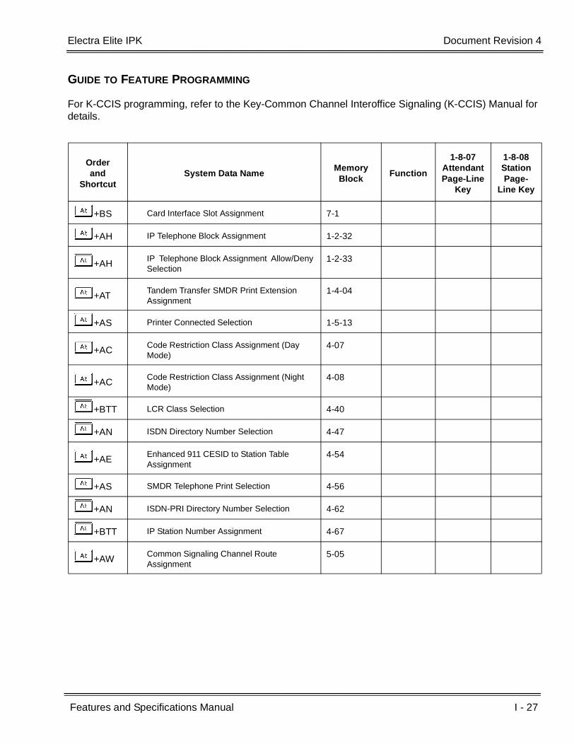
Electra Elite IPK Document Revision 4
Features and Specifications Manual I - 27
___________________________________________________________________________________
___________________________________________________________________________________
GUIDE TO FEATURE PROGRAMMING
For K-CCIS programming, refer to the Key-Common Channel Interoffice Signaling (K-CCIS) Manual for details.
Orderand
ShortcutSystem Data Name
Memory Block
Function
1-8-07AttendantPage-Line
Key
1-8-08StationPage-
Line Key
+BS Card Interface Slot Assignment 7-1
+AH IP Telephone Block Assignment 1-2-32
+AHIP Telephone Block Assignment Allow/Deny Selection
1-2-33
+ATTandem Transfer SMDR Print Extension Assignment
1-4-04
+AS Printer Connected Selection 1-5-13
+ACCode Restriction Class Assignment (Day Mode)
4-07
+ACCode Restriction Class Assignment (Night Mode)
4-08
+BTT LCR Class Selection 4-40
+AN ISDN Directory Number Selection 4-47
+AEEnhanced 911 CESID to Station Table Assignment
4-54
+AS SMDR Telephone Print Selection 4-56
+AN ISDN-PRI Directory Number Selection 4-62
+BTT IP Station Number Assignment 4-67
+AWCommon Signaling Channel Route Assignment
5-05

I - 28 IP CPU & Media Gateway
___________________________________________________________________________________
___________________________________________________________________________________Document Revision 4 Electra Elite IPK
THIS PAGE INTENTIONALLY LEFT BLANK

Features and Specifications Manual I - 29
___________________________________________________________________________________
___________________________________________________________________________________
IP Station (MEGACO) I-8
FEATURE DESCRIPTION
The IAD(8)-U( ) ETU with IP Station (MEGACO) application loaded is an optional interface package for the Electra Elite IPK system that converts digital station ports into MEGACO IP station ports. An onboard 10/100 base T connector provides a WAN/LAN connection. Voice and signaling data from/to the IP stations are converted into IP Frames and transmitted through the Data Communication IP Network Intranet or Internet. The IAD(8)-U( ) ETU supports station to station direct RTP connections (peer-to-peer) for calls between IP telephones. Each IAD(8)-U( ) ETU supports up to eight IP telephones.
The IAD ETU contains a regular TCP/RTP/IP stack that can handle real time media, supports industry standard MEGACO (H.248) communication on the WAN side, and interfaces with the Electra Elite IPK as a regular Electronic Station Interface board [ESI(8)-U( ) ETU].
From the network administration perspective, the IAD ETU is an end point on the IP network.
This interface can provide:
MEGACO (H.248) signaling Protocol
DTMF generation
RTP port number designation
TOS field QOS support
Tone generation
General Tone detection
G.711 and G.729a voice compression
10/100 BASE-T LAN interface
Echo Canceller
Remote configuration and maintenance

I - 30 IP Station (MEGACO)
___________________________________________________________________________________
___________________________________________________________________________________Document Revision 4 Electra Elite IPK
SYSTEM AVAILABILITY
Terminal type:
ITH-16D-2 Multiline Terminal
- OR -
ITH-8D-2 Multiline Terminal
- OR -
Any IPK Multiline Terminal with IP-R(IPK) Unit installed.
- OR -
IPK Soft Phone
Required Software:
R1500~R1700 or R2500
Required Components:
IAD(8)-U( ) ETU with IP Station (MEGACO) application loaded
AC-R UNIT (AC Adapter) (When in-line power is used, power over Ethernet, is not provided.)
OPERATING PROCEDURES
Normal Multiline Terminal call handling procedures apply.
SERVICE CONDITIONS
General:
For this feature, the IAD(8)-U( ) ETU is installed and assigned as an ESI (8)-U( ) ETU. Each IAD(8)-U( ) ETU supports up to eight IP Phones and reduces the maximum capacity of stations in the system by eight.
A maximum of 14 IAD(8)-U( ) ETUs can be installed supporting the maximum of 112 stations (refer to KSU Power-Based ETU Quantity Limitations in Universal Slots of the Features and Specifications manual).
The IAD (8)-U( ) supports only those vocoders that are approved to provide toll-quality speech path. The following voice compression methods are supported for the IP Station (MEGACO) application:
G.711 u Law - Highest Bandwidth
G.729 - Mid-Range Bandwidth

Electra Elite IPK Document Revision 4
Features and Specifications Manual I - 31
___________________________________________________________________________________
___________________________________________________________________________________
Each voice call requires at least the specifications listed in the following table.
This includes all the overheads of VoIP communication, including signaling).
The IAD(8)-U( ) ETU contains a regular TCP/RTP/IP stack that can handle real time media. The IAD ETU is an end-point on the IP network from the network administration perspective.
The IAD(8)-U( ) ETU uses MEGACO (H.248) Protocol to provide telephony services between remote stations through the IP Network. This is an IETF/ITU standards-based protocol. Currently, this protocol does not allow for communications across networks where Network Address Translation (NAT) is performed.
Speech-connection audio quality depends greatly on the available bandwidth between the stations in the data network. Because Internet is an uncontrolled data network compared to an Intranet, using this application in Intranet WAN environment with known (or controlled and assured) Quality of Service (QoS) is highly recommended.
When any network where the IAD(8)-U( ) ETU or any of its IP terminals is connected uses NAT for connecting the voice calls (including firewall), consulting your network provider/administrator to specifically request service for VoIP or real-time media support on your networks is recommended.
A static IP Address is required for each IAD(8)-U( ) ETU in the network.
The IAD(8)-U( ) ETU supports station to station direct RTP connections (peer-to-peer) for calls between IP Phones that provide the following benefits:
Improved voice quality for calls between two IP Phones
Improved bandwidth performance for voice between IP Phones
The operating mode can be configured per IAD(8)-U( ) ETU on each port.
Pad and echo canceler controls are built-in and are programmable in the IAD(8)-U( ) ETU.
The LAN/WAN connection is provided by a 10/100 Base T Ethernet.
CodecTransmit Data Rate
ReceiveData Rate
Time Between Packets
Packetization Delay
Default Jitter Buffer Delay
Theoretical Maximum
MOS
G711u Law 90 Kbps 90 Kbps 20 ms* 1.5 ms 2 datagrams(40 ms)
4.4
G729 34 Kbps 34 Kbps 20 ms* 15.0 ms 2 datagrams(40 ms)
4.07
In voice communication, particularly Internet telephony, the mean opinion score (MOS) provides a numerical measure of the quality of human speech at the circuit destination. The scheme uses subjective tests (opinionated scores) that are mathematically averaged to obtain a quantitative indicator of the system performance. The maximum MOS is 5.0.
* When an IP Soft Phone is connected, set Time Between Packets to 100ms.

I - 32 IP Station (MEGACO)
___________________________________________________________________________________
___________________________________________________________________________________Document Revision 4 Electra Elite IPK
RESTRICTIONS:
The Synchronous Ringing feature is not supported for IP Terminals. The ITH-16D-2 and ITH-8D-2 Multiline Terminals have user programmable ringing options.
Group listening is not supported by (MEGACO) IP stations.
Station Relocation is not supported by (MEGACO) IP stations or IPK Soft Phones.
Not all data networks are suitable to support Voice over Internet Protocol (VoIP). A good VoIP network solution requires low-latency, low jitter, and low packet loss. Accordingly, the network must be evaluated for these factors to determine whether or not it can provide toll-quality speech paths.
When 5-, 6-, or 7-digit station numbers are used, this feature is not available.
Night Mode is indicated as N on an IPK Soft Phone.
RELATED FEATURE LIST
GUIDE TO FEATURE PROGRAMMING
Feature Number
Feature Name
E-2 Electra Elite IPK Terminals
K-1 Key-Common Channel Interoffice Signaling (K-CCIS)
V-3 Voice Over Internet Protocol (VoIP) Trunk Card
Orderand
ShortcutSystem Data Name
Memory Block
Function
1-8-07AttendantPage-Line
Key
1-8-08StationPage-
Line Key
+BS Card Interface Slot Assignment 7-1
+BS Telephone Type Assignment 7-2
+BTT CO/PBX Ring Assignment (Day Mode) 4-01
+BTT CO/PBX Ring Assignment (Night Mode) 4-02
+BTM Line Key Selection for Telephone Mode 4-12

Features and Specifications Manual I - 33
___________________________________________________________________________________
___________________________________________________________________________________
ISDN-BRI Trunk Connections I-9
FEATURE DESCRIPTION
Integrated Service Digital Network - Basic Rate Interface (ISDN-BRI) is a Public Switched Telephone Network (PSTN) service that provides two B channels and a D channel (2B + D) for voice call trunking. The B channels provide two CO/PBX connections. Caller ID is usually a standard feature on ISDN-BRI provided trunks. Caller ID indication displays the calling party telephone number on the LCD of the Multiline Terminal for CO incoming calls. This interface provides voice communication path only.
ENHANCEMENTS
With System Software R1.03 or higher and BRI firmware 1.31 or higher, Caller ID Name is supported on ISDN-BRI trunks when the Telco provides this ability.
For R4000 or higher, BRT(4)-U20 with Firmware 3.00 or higher is required to support DID for ISDN-BRI trunks.
This feature allows BRI and DID callers with non-matching SPID Numbers to determine whether or not the system checks the called party number with the SETUP message and the SPID setup. Depending on Memory Block 3-77 (ISDN-BRI/PRI Directory Number Checking Selection) DID calls can be received on BRI trunks and directed according to Memory Block 1-1-22 (DID Translation Table).
Special Conditions Related to Ordering Did Service For ISDN-BRI
Telcos may refer to this in different ways. The reference Verizon uses to order such service is Additional Directory Numbers with no new terminating equipment (only a dialable number). When you want Additional Directory Numbers to hunt when a B-Channel is busy, the service may be called Busy Diversion.
SYSTEM AVAILABILITY
Terminal Type:
Not applicable
Required Components:
To provide ISDN trunk connection:
BRT(4)-U( ) ETU
I - 34 ISDN-BRI Trunk Connections
___________________________________________________________________________________
___________________________________________________________________________________Document Revision 4 Electra Elite IPK
CLKG-U( ) Unit
NT-1 for each BRI (locally provided)
OPERATING PROCEDURES
Normal call handling procedures apply.
SERVICE CONDITIONS
General:
BRT(4)-U( ) ETUs can be installed in any Interface Slot (1~8) of any Cabinet (1~3).
With an Electra Elite IPK - Basic port package, a maximum of two BRT(4)-U( ) ETUs can be installed to support 16 ISDN trunks (B channels).
With an Electra Elite IPK - Expanded port package, a maximum of eight BRT(4)-U( ) ETUs can be installed to support 64 ISDN trunks (B channels).
ISDN Trunk DTMF Duration/Interdigit Selection is effective after Answer Supervision is received from the CO.
When an ISDN line Layer 1 or Layer 2 down condition occurs, the CO line key red LED is on, and the following message is displayed on the second line of the LCD of the Multiline Terminals connected to Port 01:
Layer 1 Down: COxx Layer1 DOWN
Layer 2 Down: COxx Layer2 DOWN
xx represents the CO Trunk number (01-64).
Layer 1 down display has a higher priority than Layer 2 down. This error display disappears automatically when Layer 1/Layer 2 error is recovered. The T1 line error display has a higher priority than ISDN line Layer 1/Layer 2 down.
When ISDN-BRI trunks are used for DID, the last four digits of the 10 digit Directory Number can be used for routing the number with digit conversion.
Restrictions:
The Electra Elite IPK ISDN-BRI provides voice communication only.
The system does not support multipoint access.
The Electra Elite IPK supports the NI-1 (National ISDN-1) protocol. The AT&T and Nortel proprietary protocols are not supported.
The BRT(4)-U( ) ETU supports the S/T-type interface but not the U interface.
Electra Elite IPK Document Revision 4
Features and Specifications Manual I - 35
___________________________________________________________________________________
___________________________________________________________________________________
Caller ID Name to Single Line Telephone is NOT supported for ISDN (BRT/PRT) Trunks.
ISDN-BRI DID Service
When two BRI Directory Numbers have assigned Service Profile Identifiers (SPIDs) and Terminal Endpoint Identifiers (TEIs), Additional Directory Numbers must be pointed to the existing TEIs and be able to hunt between the existing B-Channels. An example of a BRI circuit with DID service is shown below:
214-262-0121 first Directory Number
214-262- 0122 second Directory Number
21426201210101 first SPID
21426201220101 second SPID
Additional Directory Numbers (dialable numbers terminating to existing TEIs) for the ISDN-BRI circuit can include:
214-262-0013
214-262-0014
214-262-0015
214-262-0016
214-262-0017
214-262-0018
Some Tariffs limit the number of Additional Directory Numbers that can be assigned to an ISDN-BRI circuit. A programming example is provided below:
Memory Block 3-91(Trunk Type Selection) assigns DID for the ISDN-BRI trunks.
Memory Block 3-03 (Trunk-to-Trunk Group Assignment) assigns a trunk group for the ISDN-BRI trunks.
Memory Block 3-50 (ISDN line SPID Assignment) assigns SPID numbers for the ISDN-BRI trunks.
Memory Block 3-52 (ISDN Trunk Directory Number Assignment) assigns Directory Numbers for the ISDN-BRI trunks.
Memory Block 3-77 (ISDN-BRI/PRI Directory Number Checking Assignment) is set to NO to allow the Directory Number received in the Setup Message to be passed to the CPU and analyzed by the digit conversion table.
Memory Block 1-1-20 (DID Digit Length Selection) assigns the number of digits that must be analyzed based on the last four digits of the 10-digit number received.
Memory Block 1-1-21(DID Digit Conversion Assignment) allows Digit Conversion.
Memory Block 1-1-22(DID Digit Conversion Table) enters the digits to be analyzed and assigns them to the applicable station number for each Directory Number.

I - 36 ISDN-BRI Trunk Connections
___________________________________________________________________________________
___________________________________________________________________________________Document Revision 4 Electra Elite IPK
RELATED FEATURE LIST
GUIDE TO FEATURE PROGRAMMING
(CO Line Services)
Feature Number
Feature Name
A-23 Automatic Number Indication (ANI) on T1
C-5 Caller ID Indication (Analog Trunks)
D-9 Direct Inward Dialing (DID)
I-10 ISDN-PRI Trunk Connections
M-6 Multiple Trunk Groups
U-5 Universal Slots
Orderand
ShortcutSystem Data Name
Memory Block
Function
1-8-07AttendantPage-Line
Key
1-8-08StationPage-
Line Key
+BS Card Interface Slot Assignment 7-1
+AD Master Clock Selection 1-8-33
+AN ISDN DTMF Duration/Interdigit Selection 1-1-80
+AN ISDN Dial Interval Time Selection 1-1-81
+BCT Trunk Internal Transmit Pad Selection 3-29
+BCT Trunk Internal Receive Pad Selection 3-30
+BCT Trunk External Transmit Pad Selection 3-31
+BCT Trunk External Receive Pad Selection 3-32
+AN ISDN Line SPID Assignment 3-50
+AN ISDN Trunk Directory Number Assignment 3-52
+ANISDN-PRI/BRI Directory Number Checking Selection
3-77
+BTM Line Key Selection for Telephone Mode 4-12
+BTT CO/PBX Ring Assignment (Day Mode) 4-01

Electra Elite IPK Document Revision 4
Features and Specifications Manual I - 37
___________________________________________________________________________________
___________________________________________________________________________________
(Calling Party Number [CPN] Service)
+BTT CO/PBX Ring Assignment (Night Mode) 4-02
+BTMExtension Line Key Ring Assignment (Day Mode)
4-37
+BTMExtension Line Key Ring Assignment (Night Mode)
4-38
When the system is at default this Memory Block must be programmed for the feature to be used.
Orderand
ShortcutSystem Data Name
Memory Block
Function
1-8-07AttendantPage-Line
Key
1-8-08StationPage-
Line Key
+BS Card Interface Slot Assignment 7-1
+BS MIF (Caller ID) Assignment 7-3-04
+ AICaller ID Display Assignment for System Mode (R1600 or lower)
1-1-78
+BTS Class of Service (Station) Feature Selection 2 1-8-08 4-3, 4-4,
5-7, 6-5
+BCT DIT Assignment 3-42
+BCT ANA Assignment 3-43
+ AICaller ID Display Assignment for CO/PBX Line (R1600 or lower)
3-44
+ AI Caller Name Indication Selection 3-53
+AN ISDN-PRI/BRI Directory Number Checking
Selection3-77
+BTT CO/PBX Ring Assignment (Day Mode) 4-01
+BTT CO/PBX Ring Assignment (Night Mode) 4-02
+BTM Line Key Selection for Telephone Mode 4-12
Orderand
ShortcutSystem Data Name
Memory Block
Function
1-8-07AttendantPage-Line
Key
1-8-08StationPage-
Line Key
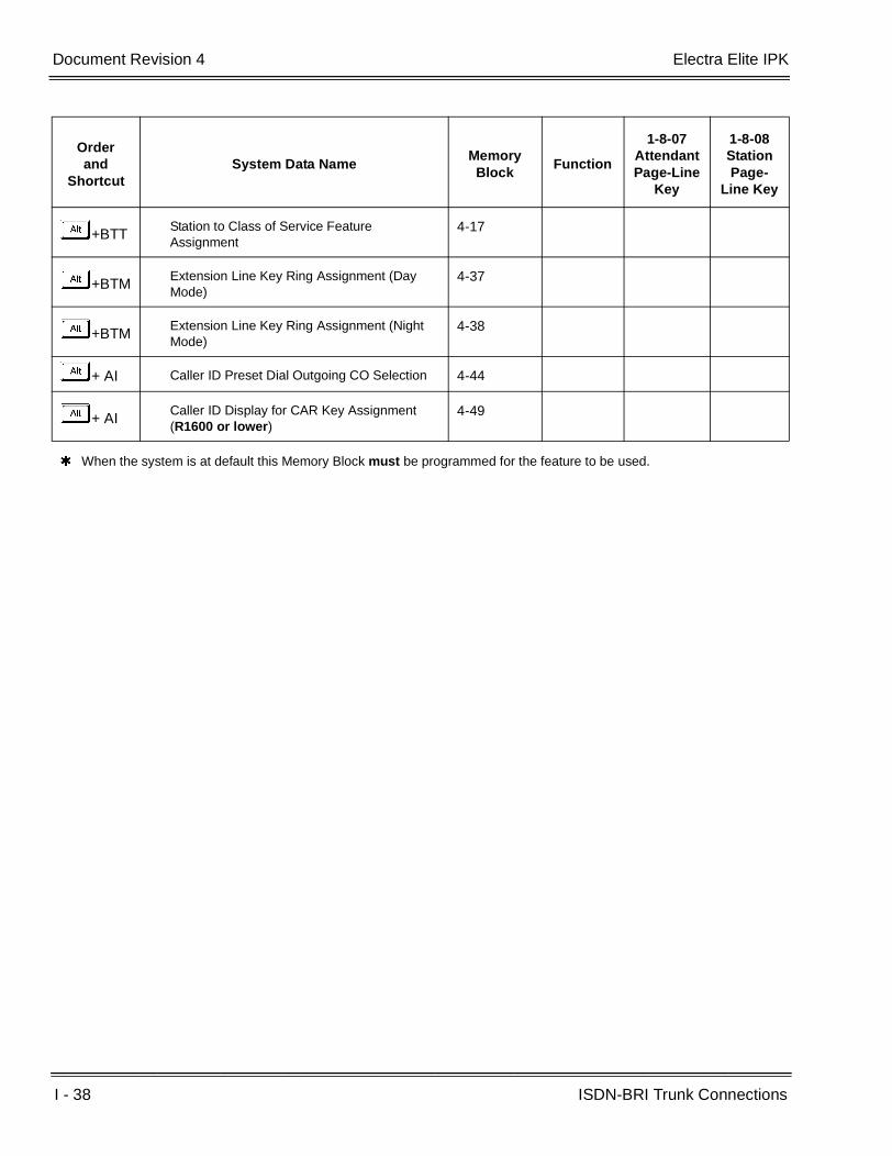
I - 38 ISDN-BRI Trunk Connections
___________________________________________________________________________________
___________________________________________________________________________________Document Revision 4 Electra Elite IPK
+BTTStation to Class of Service Feature Assignment
4-17
+BTMExtension Line Key Ring Assignment (Day Mode)
4-37
+BTMExtension Line Key Ring Assignment (Night Mode)
4-38
+ AI Caller ID Preset Dial Outgoing CO Selection 4-44
+ AICaller ID Display for CAR Key Assignment (R1600 or lower)
4-49
When the system is at default this Memory Block must be programmed for the feature to be used.
Orderand
ShortcutSystem Data Name
Memory Block
Function
1-8-07AttendantPage-Line
Key
1-8-08StationPage-
Line Key

Features and Specifications Manual I - 39
___________________________________________________________________________________
___________________________________________________________________________________
ISDN-PRI Trunk Connections I-10
FEATURE DESCRIPTION
ISDN-PRI (Integrated Service Digital Network - Primary Rate Interface) is a Public Switched Telephone Network (PSTN) service that provides 23 B channels (16 B channels for the Electra Elite IPK - Basic port package) and a single D channel (23B+1D) for trunking. The Electra Elite IPK supports CO Line or DID Line type connections. The following services are available with an ISDN-PRI circuit.
CO Line Service
When configured for CO Line Service, the trunks emulate Loop Start or Ground Start trunks for both outgoing and incoming calls.
DID Line Service
When configured for DID Line Service, the trunks emulate Loop Start or Ground Start trunks for outgoing calls and DID trunks for incoming calls.
Call By Call Service
Call By call Service allows multiple services to share a PRI line. When a call is originated or terminated, an Information Element (IE) called the Network Specified Facility (NSF) is added to the SETUP message to identify the service associated with the call.
Calling Party Number (CPN) Service
Calling Party Number (CPN) Service can display the calling party telephone number and/or name on the LCD of the Multiline Terminal for incoming calls. This emulates Caller ID Indication of Analog Trunks.
Calling Party Number (CPN) Presentation from Station
Calling Party Number (CPN) Presentation from Station allows each unique station 10-digit number (representing the DID number of the originating station) to be sent out over the PRI circuit.
Enhanced 911 Service with ISDN PRI
Enhanced 911 Service is supported by defining an available ISDN PRI trunk as a E911 trunk. When a station user dials 911, 9+ 911, or CO line key + 911, the E911 trunk is selected and the Public Safety Answering Point (PSAP) is called. The PSAP is provided callback information generated from the Electra Elite IPK system.
I - 40 ISDN-PRI Trunk Connections
___________________________________________________________________________________
___________________________________________________________________________________Document Revision 4 Electra Elite IPK
SERVICE CONDITIONS
General:
PRT(1)-U( ) ETUs can be installed in any Interface Slot (1~8) of any cabinet (1~3) without requiring adjacent slots to be vacant.
When an ISDN line layer 1 or layer 2 down condition occurs, the CO line key LED in On (Red), and the following error message is displayed on the first line of the LCD of Multiline Terminals connected to port 1:
Layer 1 Down: COxx Layer 1 DOWN
Layer 2 Down: COxx Layer 2 DOWN
xx is the CO Trunk Number (01~64).
Layer 1 has a higher priority than Layer 2.
This display disappears automatically when the error is recovered.
A PRT Firmware Upgrade Kit can be used to upgrade the firmware loaded in PRT(1)-U( ) ETUs.
Restrictions:
PRT(1)-U( ) ETUs can be assigned in Memory Block 7-1 (Card Interface Slot Assignment) with the following configurations:
PRT4 (4 ports, 4 B channels)
PRT8 (8 ports, 8 B channels)
PRT12 (12 ports, 12 B channels)
PRT16 (16 ports, 16 B channels)
PRT20 (20 ports, 20 B channels)
PRT24 (24 ports, 23 B channels)
With an Electra Elite IPK - Basic port package, a maximum of 16 ISDN trunks (B channels) can be assigned.
With an Electra Elite IPK - Expanded port package, up to 62 ISDN trunks (B channels) can be assigned when three PRT ETUs are installed. The first two ETUs provide 23 B channels, and the third ETU provides 16 B channels (23+23+16 = 62).
With an Electra Elite IPK - Basic port package, a maximum of four PRT(1)-U( ) ETUs can be installed. When four PRT ETUs are installed, up to four trunks each can be assigned.
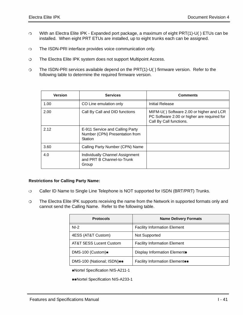
Electra Elite IPK Document Revision 4
Features and Specifications Manual I - 41
___________________________________________________________________________________
___________________________________________________________________________________
With an Electra Elite IPK - Expanded port package, a maximum of eight PRT(1)-U( ) ETUs can be installed. When eight PRT ETUs are installed, up to eight trunks each can be assigned.
The ISDN-PRI interface provides voice communication only.
The Electra Elite IPK system does not support Multipoint Access.
The ISDN-PRI services available depend on the PRT(1)-U( ) firmware version. Refer to the following table to determine the required firmware version.
Restrictions for Calling Party Name:
Caller ID Name to Single Line Telephone is NOT supported for ISDN (BRT/PRT) Trunks.
The Electra Elite IPK supports receiving the name from the Network in supported formats only and cannot send the Calling Name. Refer to the following table.
Version Services Comments
1.00 CO Line emulation only Initial Release
2.00 Call By Call and DID functions MIFM-U( ) Software 2.00 or higher and LCR PC Software 2.00 or higher are required for Call By Call functions.
2.12 E-911 Service and Calling Party Number (CPN) Presentation from Station
3.60 Calling Party Number (CPN) Name
4.0 Individually Channel Assignment and PRT B Channel-to-Trunk Group
Protocols Name Delivery Formats
NI-2 Facility Information Element
4ESS (AT&T Custom) Not Supported
AT&T 5ESS Lucent Custom Facility Information Element
DMS-100 (Custom) Display Information Element
DMS-100 (National; ISDN) Facility Information Element
Nortel Specification NIS-A211-1
Nortel Specification NIS-A233-1
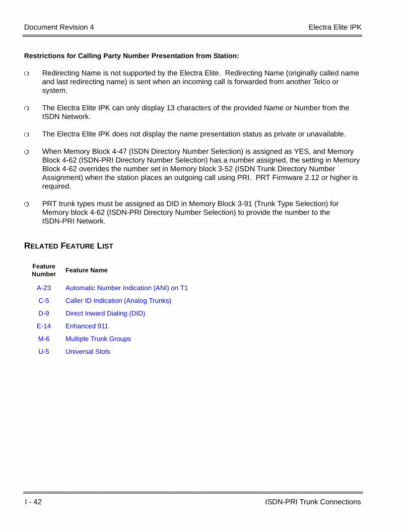
I - 42 ISDN-PRI Trunk Connections
___________________________________________________________________________________
___________________________________________________________________________________Document Revision 4 Electra Elite IPK
Restrictions for Calling Party Number Presentation from Station:
Redirecting Name is not supported by the Electra Elite. Redirecting Name (originally called name and last redirecting name) is sent when an incoming call is forwarded from another Telco or system.
The Electra Elite IPK can only display 13 characters of the provided Name or Number from the ISDN Network.
The Electra Elite IPK does not display the name presentation status as private or unavailable.
When Memory Block 4-47 (ISDN Directory Number Selection) is assigned as YES, and Memory Block 4-62 (ISDN-PRI Directory Number Selection) has a number assigned, the setting in Memory Block 4-62 overrides the number set in Memory block 3-52 (ISDN Trunk Directory Number Assignment) when the station places an outgoing call using PRI. PRT Firmware 2.12 or higher is required.
PRT trunk types must be assigned as DID in Memory Block 3-91 (Trunk Type Selection) for Memory block 4-62 (ISDN-PRI Directory Number Selection) to provide the number to the ISDN-PRI Network.
RELATED FEATURE LIST
Feature Number
Feature Name
A-23 Automatic Number Indication (ANI) on T1
C-5 Caller ID Indication (Analog Trunks)
D-9 Direct Inward Dialing (DID)
E-14 Enhanced 911
M-6 Multiple Trunk Groups
U-5 Universal Slots

Electra Elite IPK Document Revision 4
Features and Specifications Manual I - 43
___________________________________________________________________________________
___________________________________________________________________________________
GUIDE TO FEATURE PROGRAMMING
ISDN – PRI Installation
Orderand
ShortcutSystem Data Name
Memory Block
Function
1-8-07AttendantPage-Line
Key
1-8-08StationPage-
Line Key
+BS Card Interface Slot Assignment 7-1
+AD Master Clock Selection 1-8-33
+AN ISDN DTMF Duration/Interdigit Selection 1-1-80
+AN PRT Channel Assignment 1-13-00
+AN PRT Signal Format Selection 1-13-01
+AN Clear Channel Selection 1-13-02
+AN Call by Call Service Selection 1-13-03
+AN PRT B Channel Outgoing Priority Selection 1-13-04
+AN PRT B Channel-to-Trunk Group Assignment 1-13-05
+BCT Trunk-to-Trunk Group Assignment 3-03
+BCT Trunk Internal Transmit Pad Selection 3-29
+BCT Trunk Internal Receive Pad Selection 3-30
+BCT Trunk External Transmit Pad Selection 3-31
+BCT Trunk External Receive Pad Selection 3-32
+BCT Trunk Type Selection 3-91

I - 44 ISDN-PRI Trunk Connections
___________________________________________________________________________________
___________________________________________________________________________________Document Revision 4 Electra Elite IPK
CO Line Services
Orderand
ShortcutSystem Data Name
Memory Block
Function
1-8-07AttendantPage-Line
Key
1-8-08StationPage-
Line Key
+BCT Trunk Type Selection 3-91
+AN ISDN Trunk Directory Number Assignment 3-52
+ANISDN Trunk Directory Number Checking Selection
3-77
+BTT CO/PBX Ring Assignment (Day Mode) 4-01
+BTT CO/PBX Ring Assignment (Night Mode) 4-02
+BTM Line Key Selection for Telephone Mode 4-12
When the system is at default this Memory Block must be programmed for the feature to be used.
DID Line Service
Orderand
ShortcutSystem Data Name
Memory Block
Function
1-8-07AttendantPage-Line
Key
1-8-08StationPage-
Line Key
+BCT Trunk Type Selection 3-91
+ALNDigit Add/Delete for Tie Line Networking Assignment
5-00
+ALN DID Digit Length Selection 1-1-20
+ALN DID Digit Conversion Assignment 1-1-21
+ALN DID Digit Conversion Table 1-1-22
+ALNDID Forward Station Number for Busy Station or Undefined Digit
1-1-23
When the system is at default this Memory Block must be programmed for the feature to be used.
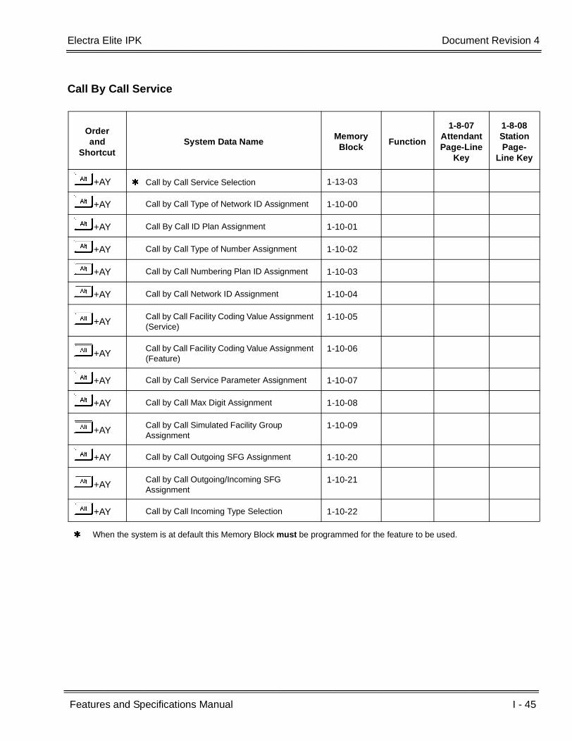
Electra Elite IPK Document Revision 4
Features and Specifications Manual I - 45
___________________________________________________________________________________
___________________________________________________________________________________
Call By Call Service
Orderand
ShortcutSystem Data Name
Memory Block
Function
1-8-07AttendantPage-Line
Key
1-8-08StationPage-
Line Key
+AY Call by Call Service Selection 1-13-03
+AY Call by Call Type of Network ID Assignment 1-10-00
+AY Call By Call ID Plan Assignment 1-10-01
+AY Call by Call Type of Number Assignment 1-10-02
+AY Call by Call Numbering Plan ID Assignment 1-10-03
+AY Call by Call Network ID Assignment 1-10-04
+AYCall by Call Facility Coding Value Assignment (Service)
1-10-05
+AYCall by Call Facility Coding Value Assignment (Feature)
1-10-06
+AY Call by Call Service Parameter Assignment 1-10-07
+AY Call by Call Max Digit Assignment 1-10-08
+AYCall by Call Simulated Facility Group Assignment
1-10-09
+AY Call by Call Outgoing SFG Assignment 1-10-20
+AYCall by Call Outgoing/Incoming SFG Assignment
1-10-21
+AY Call by Call Incoming Type Selection 1-10-22
When the system is at default this Memory Block must be programmed for the feature to be used.

I - 46 ISDN-PRI Trunk Connections
___________________________________________________________________________________
___________________________________________________________________________________Document Revision 4 Electra Elite IPK
Calling Party Number (CPN) Service
Orderand
ShortcutSystem Data Name
Memory Block
Function
1-8-07AttendantPage-Line
Key
1-8-08StationPage-
Line Key
+BS MIF (Caller ID) Assignment 7-3-04
+AICaller ID Display Assignment for System Mode (R1600 or lower)
1-1-78
+BTSClass of Service (Station) Feature Selection 2 1-8-08 4-3, 4-4,
5-7, 6-5
+AICaller ID Display Assignment for CO/PBX Line (R1600 or lower)
3-44
+BTTStation to Class of Service Feature Assignment
4-17
+AI Caller ID Preset Dial Outgoing CO Selection 4-44
+AICaller ID Display for CAR Key Assignment (R1600 or lower)
4-49
Calling Party Number (CPN) Presentation from Station
Orderand
ShortcutSystem Data Name
Memory Block
Function
1-8-07AttendantPage-Line
Key
1-8-08StationPage-
Line Key
+BCT Trunk Type Selection 3-91
+AN ISDN Directory Number Selection 4-47
+AN ISDN-PRI Directory Number Selection 4-62
When the system is at default this Memory Block must be programmed for the feature to be used.

Electra Elite IPK Document Revision 4
Features and Specifications Manual I - 47
___________________________________________________________________________________
___________________________________________________________________________________
Enhanced 911 Service with ISDN-PRI
Orderand
ShortcutSystem Data Name
Memory Block
Function
1-8-07AttendantPage-Line
Key
1-8-08StationPage-
Line Key
+AE Enhanced 911 Trunk Assignment 1-8-43
+AE Enhanced 911 Alternate Route Assignment 1-8-44
+AEEnhanced 911 Alternate Route Assignment (Maintenance Busy)
1-8-45
+AE Enhanced 911 Dialing Digit Assignment 1-8-46
+BCT Trunk-to-Trunk Group Assignment 3-03
+AN ISDN Trunk Directory Number Assignment 3-52
+AE Enhanced 911 CESID to Station Table
Assignment4-54
When the system is at default this Memory Block must be programmed for the feature to be used.

I - 48 ISDN-PRI Trunk Connections
___________________________________________________________________________________
___________________________________________________________________________________Document Revision 4 Electra Elite IPK
THIS PAGE INTENTIONALLY LEFT BLANK

Features and Specifications Manual I - 49
___________________________________________________________________________________
___________________________________________________________________________________
I-Use Indication I-11
FEATURE DESCRIPTION
I-Use Indication provides a green LED line key indication for the line being used on Multiline Terminals. Other busy line keys are indicated with red LEDs. This quickly identifies the line being used by the station user.
SYSTEM AVAILABILITY
Terminal Type:
All Multiline Terminals
Required Components:
None
OPERATING PROCEDURES
None
SERVICE CONDITIONS
General:
The indication is a green LED when a CO/PBX line is in use or a winking green LED when the line is on hold.
All other Multiline Terminals with that line appearance show a red LED.
When a Multiline Terminal does not have a CO/PBX line appearance on a Flexible Line key, the I-Use is indicated on a Call Appearance key LED.
When a Multiline Terminal has the CO/PBX line appearance on a Flexible Line key, the I-Use indication is indicated on the CO/PBX line key.

I - 50 I-Use Indication
___________________________________________________________________________________
___________________________________________________________________________________Document Revision 4 Electra Elite IPK
THIS PAGE INTENTIONALLY LEFT BLANK
Features and Specifications Manual K - 1
___________________________________________________________________________________
___________________________________________________________________________________
Key-Common Channel Interoffice
Signaling (K-CCIS) K-1
FEATURE DESCRIPTION
Key-Common Channel Interoffice Signaling (K-CCIS) allows multiple systems to be connected together to provide additional feature compatibility, above what normal Tie Lines provide. The system is configured with the 24-channel Digital Trunk Interface (DTI), a Common Channel Handler (CCH) for receiving or transmitting common signaling data from/to a distant office, and a CLKG-U( ) Unit for network synchronization. The system can provide a variety of interoffice service features such as Calling Name display, Centralized Voice Mail Integration, or Link Reconnect.
MIFM-U( ) Software and LCR PC software are required to program the expanded Route Advance Block Assignments in LCR.
The following features are provided:
Call Forwarding – All Calls - K-CCIS
Call Forwarding – Busy/No Answer - K-CCIS
Call Transfer – All Calls - K-CCIS
Calling Name Display - K-CCIS
Calling Number Display - K-CCIS
Call Park Retrieve - K-CCIS (R3000 or higher)
Calling Party Number (CPN) Presentation from Station – K-CCIS (R4000 or higher)
Centralized Billing - K-CCIS
Centralized BLF - (K-CCIS) (R1500 or higher) R3000 or higher is required for Centralized BLF (K-CCIS) on an Attendant Add-On Console.
Centralized Day/Night Mode Change - K-CCIS
Centralized E911 (K-CCIS) (R2000 or higher)
Dial Access to Attendant - K-CCIS
Direct Inward Dialing - K-CCIS
Dual hold - K-CCIS

K - 2 Key-Common Channel Interoffice Signaling (K-CCIS)
___________________________________________________________________________________
___________________________________________________________________________________Document Revision 4 Electra Elite IPK
Elapsed Time Display - K-CCIS
Flexible Numbering of Stations - K-CCIS
Hands-Free Answerback - K-CCIS
Hot Line - K-CCIS
IP (K-CCIS) (R1500~R1700 only)
IP (K-CCIS) to NEAX (Point-to-Multipoint) (R2500 or R3500)
Link Reconnect - K-CCIS
Multiple Call Forwarding – All Calls - K-CCIS
Multiple Call Forwarding – Busy/No Answer - K-CCIS
Paging Access - K-CCIS R3000 or higher is required for Paging Access - K-CCIS Internal/All Call Paging across K-CCIS.
Quick Transfer to Voice Mail - K-CCIS (R3000 or higher)
Station-to-Station Calling - K-CCIS
Uniform Numbering Plan - K-CCIS
Voice Call - K-CCIS
Voice Mail Integration - K-CCIS
SYSTEM AVAILABILITY
Terminal Type:
All Stations
Required Components:
DTI-U30 ETU or higher
CCH(4)-U( ) ETU with applicable firmware
CLKG-U( ) Unit (Phase Lock Oscillator)

Electra Elite IPK Document Revision 4
Features and Specifications Manual K - 3
___________________________________________________________________________________
___________________________________________________________________________________
MIFM-U10 ETU with KMM( )U installed for Call Routing using LCR When expanded Route Advanced Block assignments for Least Cost Routing (LCR) are required, MIFM-U( )
firmware V4.00 or higher and LCR PC software 3.00 or higher are required.
- OR -
MIFM-U20 ETU with KMM-U20 Upgrade Chip installed When Call Routing using LCR is required
- OR -
SPE(M)-U10 ETU
When Centralized Billing - K-CCIS is required, MIFM-U( ) firmware V5.00 or higher is required.
The following tables show the KSU system software compatibility with CCH(4)-U( ) firmware and K-CCIS feature compatibility.
KSU Software/CCH Firmware Compatibility
KSU Software CCH V1.XX CCH V2.XX CCH V3.XX CCH V4.XX
IPK R1000 R1.0X – X X X
IPK R1500 R1.5X – – X X
IPK R1600 R1.6X – – X X
IPK R1700 R1.7X – – X X
IPK R2000 R2.0X – – – X
IPK R2500 R2.5X – – – X
IPK R3000 R3.0x – – – X
IPK R3500 R3.5x – – – X
IPK R4000 R4.0x – – – X
IPK R4500 R4.5x – – – X
X = Compatible– = Not compatible
K-CCIS Feature Compatibility
K-CCIS Feature
Minimum CPU
Software Required
CCH V2.XX
CCH V3.XX
CCH V4.XX
NEAX Compatible
Call Forwarding– All Calls - K-CCIS R1000 X X X Yes
Call Forwarding – Busy/No Answer - K-CCIS R1000 X X X Yes
Call Park Retrieve - K-CCIS R3000 – – X No
Call Transfer – All Calls - K-CCIS R1000 X X X Yes

K - 4 Key-Common Channel Interoffice Signaling (K-CCIS)
___________________________________________________________________________________
___________________________________________________________________________________Document Revision 4 Electra Elite IPK
Calling Name Display - K-CCIS R1000 X X X Yes
Calling Number Display - K-CCIS R1000 X X X Yes
Calling Party Number (CPN) Presentation from Station – K-CCIS
R4000 – – X Yes
Centralized Billing - K-CCIS R1000 X X X Conditions
Centralized BLF-IPK to IPK (K-CCIS)
For Attendant Add-On Console support
R1500 – X X No
R3000 – – X No
Centralized Day/Night Mode Change - K-CCIS R1000 X X X Conditions
Centralized E911(K-CCIS) R2000 – – X Yes
Dial Access to Attendant - K-CCIS R1000 X X X Yes
Direct Inward Dialing - K-CCIS R1000 X X X Yes
Dual Hold - K-CCIS R1000 X X X Yes
Elapsed Time Display - K-CCIS R1000 X X X Yes
Flexible Numbering of Stations - K-CCIS R1000 X X X Yes
Handsfree Answerback - K-CCIS R1000 X X X Yes
Hot Line - K-CCIS R1000 X X X Yes
IP (K-CCIS) *R1500~R1700
(only)– X X No
IP (K-CCIS) to NEAX (Point-to-Multipoint) * R2500 or R3500 (only)
– – X Yes
Link Reconnect - K-CCIS R1000 X X X Yes
Multiple Call Forwarding – All Calls - K-CCIS R1000 X X X Yes
Multiple Call Forwarding – Busy/No Answer- K-CCIS
R1000 X X X Yes
Paging Access - K-CCIS
For Internal/ All Call Paging across K-CCIS support
R1000 X X X
NoR3000 – – X
Quick Transfer to Voice Mail - K-CCIS R3000 – – X No
Station-to-Station Calling - K-CCIS R1000 X X X
Uniform Number Plan - K-CCIS R1000 X X X
Voice Calls - K-CCIS R1000 X X X
K-CCIS Feature Compatibility
K-CCIS Feature
Minimum CPU
Software Required
CCH V2.XX
CCH V3.XX
CCH V4.XX
NEAX Compatible
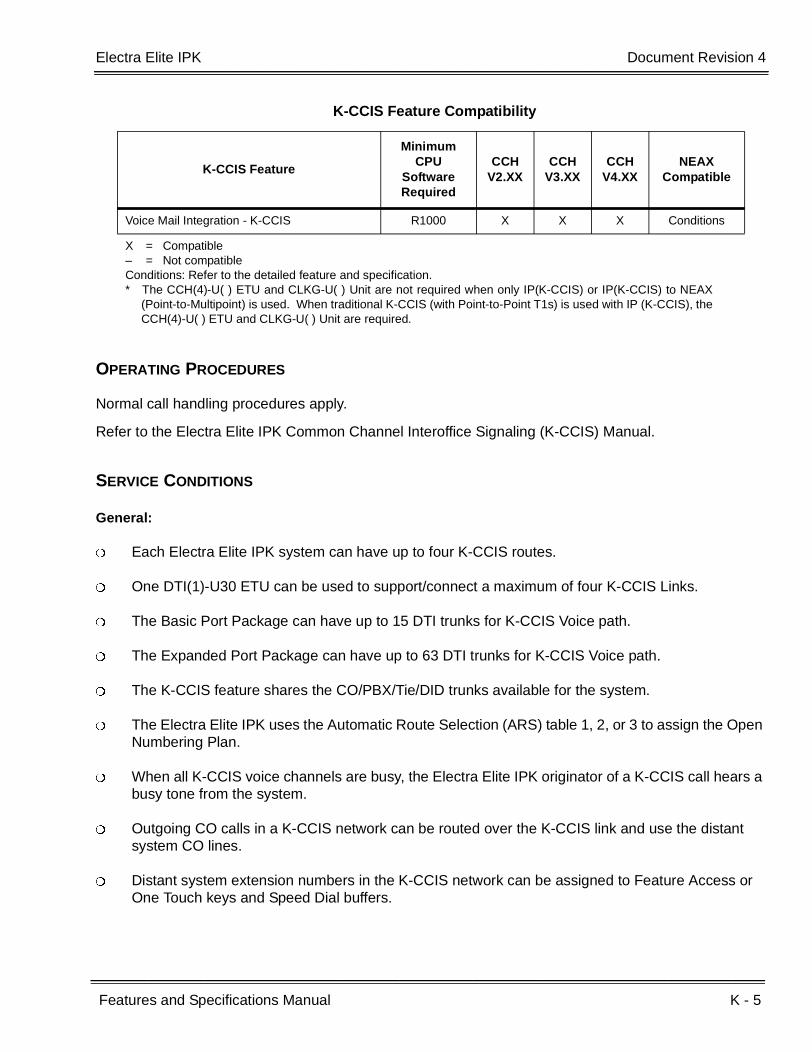
Electra Elite IPK Document Revision 4
Features and Specifications Manual K - 5
___________________________________________________________________________________
___________________________________________________________________________________
OPERATING PROCEDURES
Normal call handling procedures apply.
Refer to the Electra Elite IPK Common Channel Interoffice Signaling (K-CCIS) Manual.
SERVICE CONDITIONS
General:
Each Electra Elite IPK system can have up to four K-CCIS routes.
One DTI(1)-U30 ETU can be used to support/connect a maximum of four K-CCIS Links.
The Basic Port Package can have up to 15 DTI trunks for K-CCIS Voice path.
The Expanded Port Package can have up to 63 DTI trunks for K-CCIS Voice path.
The K-CCIS feature shares the CO/PBX/Tie/DID trunks available for the system.
The Electra Elite IPK uses the Automatic Route Selection (ARS) table 1, 2, or 3 to assign the Open Numbering Plan.
When all K-CCIS voice channels are busy, the Electra Elite IPK originator of a K-CCIS call hears a busy tone from the system.
Outgoing CO calls in a K-CCIS network can be routed over the K-CCIS link and use the distant system CO lines.
Distant system extension numbers in the K-CCIS network can be assigned to Feature Access or One Touch keys and Speed Dial buffers.
Voice Mail Integration - K-CCIS R1000 X X X Conditions
X = Compatible– = Not compatibleConditions: Refer to the detailed feature and specification.* The CCH(4)-U( ) ETU and CLKG-U( ) Unit are not required when only IP(K-CCIS) or IP(K-CCIS) to NEAX
(Point-to-Multipoint) is used. When traditional K-CCIS (with Point-to-Point T1s) is used with IP (K-CCIS), theCCH(4)-U( ) ETU and CLKG-U( ) Unit are required.
K-CCIS Feature Compatibility
K-CCIS Feature
Minimum CPU
Software Required
CCH V2.XX
CCH V3.XX
CCH V4.XX
NEAX Compatible

K - 6 Key-Common Channel Interoffice Signaling (K-CCIS)
___________________________________________________________________________________
___________________________________________________________________________________Document Revision 4 Electra Elite IPK
When a K-CCIS trunk is on hold, the Specified Line Seizure access codes can be used to retrieve the call from its held state.
Caller ID Name data received from a Telco Central Office is not passed across the K-CCIS network.
The Elite ACD Plus can support and distribute incoming calls from a remote K-CCIS office. However, incoming calls to ACD Plus that result in a link reconnect are not supported. These calls must first be answered by a local station, then can be transferred to ACD Plus as long as it is not an internal (Intercom) call.
Restrictions:
When using Calling Party Number (CPN) Presentation from Station – K-CCIS (R4000 or higher) the remote system must assign 9 to access the K-CCIS network.
The Electra Elite IPK can support only 2-, 3-, or 4-digit station numbers (R2000 or lower).
The Electra Elite IPK can support 2~7-digit station numbers (R2500).
With R2000 or lower, Station Numbers are assigned by the 100s group for 4-digit station numbers only.
With R2500, Station Numbers are assigned by the 10s group for 4-digit station numbers, 100s group for 5-digit station numbers, 1000s group for 6-digit station numbers, 10000s group for 7-digit station numbers.
When Voice Mail Message Waiting status must be sent across the K-CCIS to a remote system, the Closed Number Blocks must be used.
For a Closed Numbering Plan network using Closed Numbering Blocks, a maximum of 16 Numbering Blocks are available allowing a maximum of 17 connected systems per K-CCIS network.
When a Closed Numbering Plan Network is used, a user can call another station by dialing the distant extension number, but extensions in the network cannot have the same prefix.
When assigning a Closed Numbering Plan and DID conversion across K-CCIS is required, the Closed Number Blocks must be used.
When assigning a Closed Numbering Plan and DID conversion across K-CCIS is not required, the Automatic Route Selection (ARS) table 4 can be used.
For an Open Numbering Plan network, the ARS feature, table 1, 2 or 3 must be used to place station-to-station calls over K-CCIS.
For an Open Numbering Plan network, a user can dial another station by dialing the office location number plus an extension number and the extension number can have the same prefix, but the office location cannot be the same.
Electra Elite IPK Document Revision 4
Features and Specifications Manual K - 7
___________________________________________________________________________________
___________________________________________________________________________________
When an Electra Elite IPK system is a tandem system (in the middle) between systems with higher K-CCIS feature support (including NEAX PBXs), only the K-CCIS features supported by the tandem system (Electra Elite IPK) are passed through and supported.
An Electra Elite IPK K-CCIS network should never have more than five hops (tandem connections) because of the message delay through each tandem system.
A Star topology network supports only five systems because of the CCH channels in the Main/Hub system.
A Tree topology network is supported. The maximum number of systems depends on the Numbering Plan used and the maximum number of hops (tandem connections).
Mesh topology is not supported by the Electra Elite only network.
K-CCIS requires assigning a point code for each office. Point codes differentiate between an originating office and a destination office in the K-CCIS Network. Assigning point codes requires the following considerations:
The point code must be unique in the network.
When a system has two or more CCH channels, the same originating point code must be assigned to all channels in the system.
The Electra Elite IPK can have a maximum of 255 codes assigned to distant systems.
Using an Electra Elite IPK-to-Electra Elite IPK network, centralized voice is not supported when an Open Numbering Plan is used.
Each Electra Elite IPK system in a K-CCIS network must have at least one local trunk for Emergency 911 calls (R1700 or lower).
With R2000 or higher, Centralized E911 - K-CCIS is supported, but when it is not used, each Electra Elite IPK system in a K-CCIS network must have at least one local trunk for Emergency 911 calls.
Using a NEAX-to-Electra Elite IPK network, the PBX must supply centralized voice mail.
Multiline terminals must have an available Call Appearance (CAP) key to originate or answer a K-CCIS trunk call.
Direct access of K-CCIS voice or data channels using Line keys or Specified Line Seizure access codes is prohibited.
A Single Line Telephone or PSII user cannot transfer a trunk or K-CCIS call to another user on a remote system across K-CCIS (R1700 or lower).
With R2000 or higher, A Single Line Telephone or PSII user can perform a trunk-to-Trunk transfer, including the transfer of a trunk or K-CCIS call to another user on a remote system across K-CCIS.
Recall key or Drop key does not function on K-CCIS calls. When either key is pressed, operation is ignored, and the call continues.
Trunk queuing is prohibited on a K-CCIS trunk route.
K - 8 Key-Common Channel Interoffice Signaling (K-CCIS)
___________________________________________________________________________________
___________________________________________________________________________________Document Revision 4 Electra Elite IPK
The ability to route an incoming DID call directly across a K-CCIS link (Direct Inward Dialing-K-CCIS) is supported only when a Closed Numbering Plan using Closed Numbering Blocks is used.
This feature is not supported by the TLI(2)-U( ) Analog Line interface.
Only one CCH(4)-U( ) ETU can be assigned per system.
Extension numbers cannot start with 0 or 9.
Internal Calls, transferred calls, and K-CCIS calls do not provide Caller ID to Single Line Telephones.
RELATED FEATURE LIST
Refer to the Electra Elite IPK Key-Common Channel Interoffice Signaling (K-CCIS) Manual for more details.
Feature Number
Feature Name
T-1 T1 Connection
U-5 Universal Slots

Features and Specifications Manual K - 9
___________________________________________________________________________________
___________________________________________________________________________________
Key Function/Multifunction Registration K-2
FEATURE DESCRIPTION
The system can be registered as either a Key Function (KF) or a Multifunction (MF) telephone system. This feature is set by a switch on the CPUI( )-U( ) ETU for the Electra Elite IPK system during installation.
SYSTEM AVAILABILITY
Terminal Type:
Not applicable
Required Components:
CPUI( )-U( ) ETU
OPERATING PROCEDURES
None
SERVICE CONDITIONS
General:
When the system is set as KF, CO/PBX lines must appear on Multiline Terminals. Outside calls cannot be made by dialing a Trunk Access Code from internal dial tone except when specified trunk seizure is used.
When a system is set as KF, the following CO/PBX calls are prohibited:
Route Advance key
Trunk Group key
Hot Line/Prime Line with Automatic Trunk Selection
Trunk Group Access Call, Route Advance Access Call
K - 10 Key Function/Multifunction Registration
___________________________________________________________________________________
___________________________________________________________________________________Document Revision 4 Electra Elite IPK
Least Cost Routing (LCR)
Speed Dial with Automatic Trunk Selection
Last Number Redial with Automatic Trunk Selection
When the system is set as multifunction, CO/PBX lines can be accessed from internal dial tone by dialing a Trunk Access Code.
KF or MF selection is set by a hardware switch on the CPUI( )-U( ) ETU in the B64-U( ) KSU. To change the KF/MF selection after First Initialization of the system, First Initialization must be performed again.
In KF mode, Single Line Telephones can be used for internal calls and can access an outside line using the specified trunk seizure Access Code or Prime Line Pickup assignment.

Features and Specifications Manual L - 1
___________________________________________________________________________________
___________________________________________________________________________________
Large LED Indication L-1
FEATURE DESCRIPTION
All Multiline Terminals have a Large LED to indicate incoming calls or messages sent from the Attendant or a Voice Mail system.
SYSTEM AVAILABILITY
Terminal Type:
All Multiline Terminals
Required Components:
None
OPERATING PROCEDURES
None
SERVICE CONDITIONS
Visual Indications for the Large LED include the following:
Incoming CO/PBX Call Flashing Green 0.125 sec. ON0.125 sec. OFF
Incoming Internal Call Flashing Red 0.125 sec. ON0.125 sec. OFF
Message from AttendantAdd-On Console
Flashing Green 0.5 sec. ON0.5 sec. OFF
Message from Voice Mail Flashing Red 0.5 sec. ON0.5 sec. OFF
CO Ring Transfer Calls Flashing Green 0.125 sec. ON0.125 sec. OFF

L - 2 Large LED Indication
___________________________________________________________________________________
___________________________________________________________________________________Document Revision 4 Electra Elite IPK
Calls are in the following priority order:
1. Internal
2. CO Ring Transfer
3. CO/PBX
4. Message from Attendant Add-On Console
5. Message from Voice Mail

Features and Specifications Manual L - 3
___________________________________________________________________________________
___________________________________________________________________________________
Last Number Redial L-2
FEATURE DESCRIPTION
Last Number Redial allows the user to press the Redial key and to redial the last outside number dialed. This is useful when a busy or no answer is received when trying to place a CO/PBX call.
ENHANCEMENT(S)
R4000 or higher is required to support the last 10 numbers that were dialed.
SYSTEM AVAILABILITY
Terminal Type:
All Stations
Required Components:
None
OPERATING PROCEDURES
Using a Multiline Terminal:
Key Function:
1. Press an idle CO/PBX/Tie line key.
2. Press B .
3. Dial J.
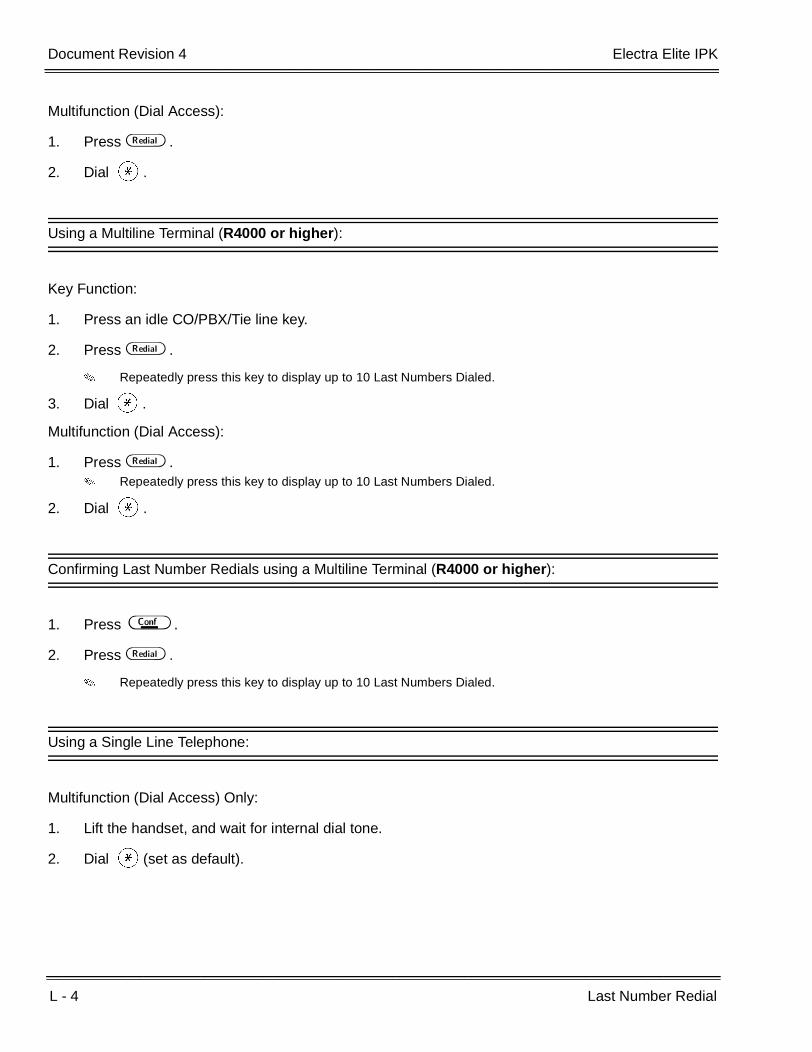
L - 4 Last Number Redial
___________________________________________________________________________________
___________________________________________________________________________________Document Revision 4 Electra Elite IPK
Multifunction (Dial Access):
1. Press B .
2. Dial J.
Using a Multiline Terminal (R4000 or higher):
Key Function:
1. Press an idle CO/PBX/Tie line key.
2. Press B .
Repeatedly press this key to display up to 10 Last Numbers Dialed.
3. Dial J.
Multifunction (Dial Access):
1. Press B . Repeatedly press this key to display up to 10 Last Numbers Dialed.
2. Dial J.
Confirming Last Number Redials using a Multiline Terminal (R4000 or higher):
1. Press D .
2. Press B .
Repeatedly press this key to display up to 10 Last Numbers Dialed.
Using a Single Line Telephone:
Multifunction (Dial Access) Only:
1. Lift the handset, and wait for internal dial tone.
2. Dial J(set as default).
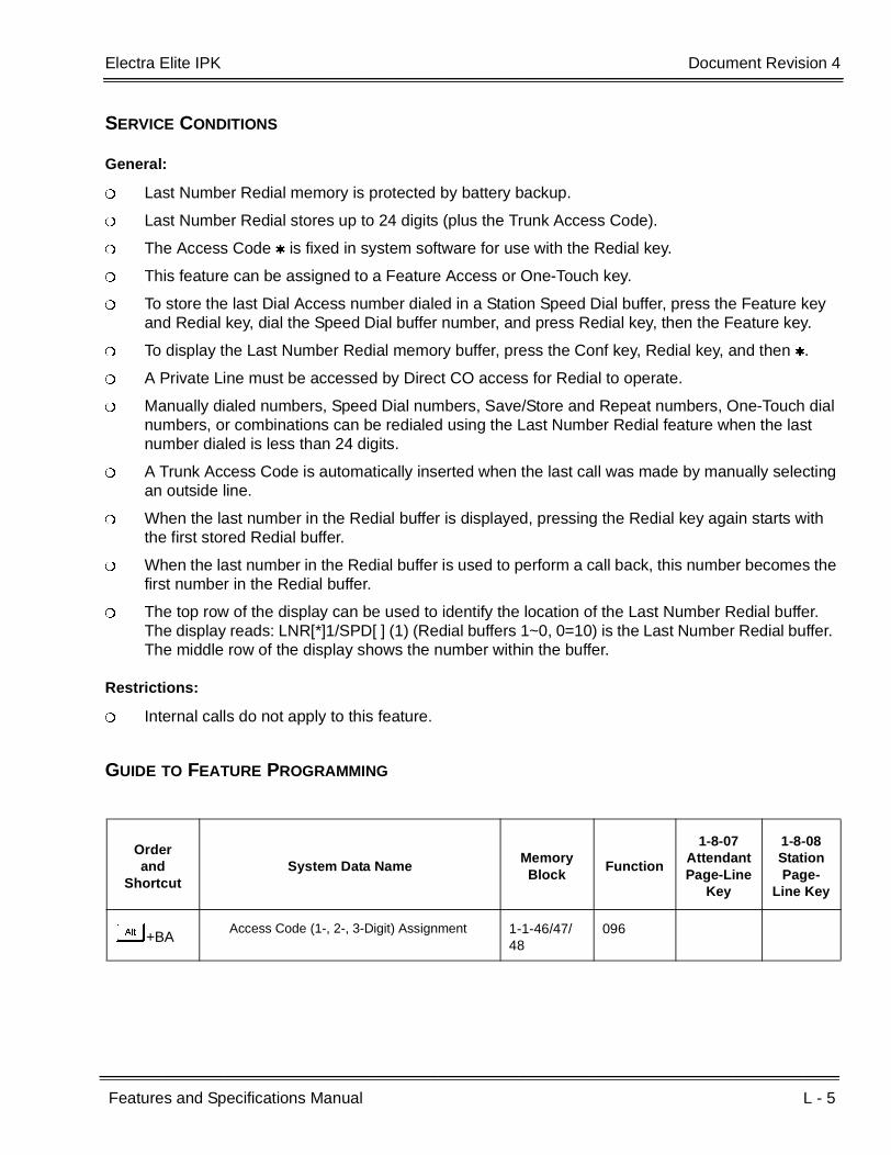
Electra Elite IPK Document Revision 4
Features and Specifications Manual L - 5
___________________________________________________________________________________
___________________________________________________________________________________
SERVICE CONDITIONS
General:
Last Number Redial memory is protected by battery backup.
Last Number Redial stores up to 24 digits (plus the Trunk Access Code).
The Access Code is fixed in system software for use with the Redial key.
This feature can be assigned to a Feature Access or One-Touch key.
To store the last Dial Access number dialed in a Station Speed Dial buffer, press the Feature key and Redial key, dial the Speed Dial buffer number, and press Redial key, then the Feature key.
To display the Last Number Redial memory buffer, press the Conf key, Redial key, and then .
A Private Line must be accessed by Direct CO access for Redial to operate.
Manually dialed numbers, Speed Dial numbers, Save/Store and Repeat numbers, One-Touch dial numbers, or combinations can be redialed using the Last Number Redial feature when the last number dialed is less than 24 digits.
A Trunk Access Code is automatically inserted when the last call was made by manually selecting an outside line.
When the last number in the Redial buffer is displayed, pressing the Redial key again starts with the first stored Redial buffer.
When the last number in the Redial buffer is used to perform a call back, this number becomes the first number in the Redial buffer.
The top row of the display can be used to identify the location of the Last Number Redial buffer. The display reads: LNR[*]1/SPD[ ] (1) (Redial buffers 1~0, 0=10) is the Last Number Redial buffer. The middle row of the display shows the number within the buffer.
Restrictions:
Internal calls do not apply to this feature.
GUIDE TO FEATURE PROGRAMMING
Orderand
ShortcutSystem Data Name
Memory Block
Function
1-8-07AttendantPage-Line
Key
1-8-08StationPage-
Line Key
+BAAccess Code (1-, 2-, 3-Digit) Assignment 1-1-46/47/
48096

L - 6 Last Number Redial
___________________________________________________________________________________
___________________________________________________________________________________Document Revision 4 Electra Elite IPK
THIS PAGE INTENTIONALLY LEFT BLANK
Features and Specifications Manual L - 7
___________________________________________________________________________________
___________________________________________________________________________________
Least Cost Routing (LCR) L-3
FEATURE DESCRIPTION
Least Cost Routing allows outside calls to use the least expensive available route. The MIFM-U( ) ETU and KMM(1.0)U provide cost effective call routing based on the time of day, day of week, weekend or holiday based on the Central Office number dialed. Call costs are minimized by automatically selecting the least expensive available connection for outgoing calls.
ENHANCEMENT(S)
Release 3000:
With R3000 or higher, Least Cost Routing (LCR) can be used with the new MIFM-U20 ETU with the KMM-U20 or the SPE(M)-U( ) ETU.
SYSTEM AVAILABILITY
Terminal Type:
All Stations
Required Components:
MIFM-U10 ETU with KMM(1.0)U
- OR -
MIFM-U20 ETU with KMM-U20
- OR -
SPE(M)-U( ) ETU

L - 8 Least Cost Routing (LCR)
___________________________________________________________________________________
___________________________________________________________________________________Document Revision 4 Electra Elite IPK
The following table compares the MIFM-U10, MIFM-U20 and SPE(M)-U( ) ETUs:
Feature MIFM-U10 ETU MIFM-U20 ETU SPE(M)-U( ) ETU
LCR Serial Programming Yes Yes Yes
LCR Modem Programming Yes Yes Yes
LCR Ethernet Programming No Yes Yes
Serial SMDR Yes Yes Yes
Ethernet SMDR NoYes
(simultaneous on serial also)Yes
(simultaneous on serial also)
SMDR Record Storage when Printer is not connected
Approximately 100 call records
Maximum of 2000 records in
non-volatile Memory
Maximum of 2000 records in
non-volatile Memory
Caller ID Storage 50 per Station50 per Station in
non-volatile Memory50 per Station in
non-volatile Memory
VM CoSession using KSU serial port (no open box)
No No Yes
VM CoSession using modem not on VM ETU
No No Yes
VM CoSession using Ethernet
No No Yes
BRT/PRT/CCH Remote Debugging
No No Yes

Electra Elite IPK Document Revision 4
Features and Specifications Manual L - 9
___________________________________________________________________________________
___________________________________________________________________________________
Some LCR functions depend on the LCR PC software and the MIFM-U( ) ETU firmware version. Use the following table to determine the required versions.
OPERATING PROCEDURES
To use this feature:
1. Lift the handset, and wait for internal dial tone.
2. Dial the CodeIand receive LCR dial tone.
3. Dial the desired number.
Function LCR PC SoftwareMIFM-U10 ETU
Firmware
Initial Release V1.00 V1.00
To route Operator/International and OCC calls through LCR
To assign Route Advanced Blocks in a Route Table for use with ISDN-PRI Call-by-Call
V2.00 V2.00
To Print SMDR data per station - Memory Block 4-56 (SMDR Telephone Print Selection)
Not Affected V3.00
To assign Expanded Route Advance Block assignments (from 16 to 32)
To add extra code digits to Operator/International and OCC calls routed through LCR
To analyze the incoming digits from a trunk group to be routed through LCR
V3.00 V4.00
Supports Centralized Billing - K-CCIS Supports 50 Caller ID scroll buffers (not LCR
related)
Not Affected V5.00
Tab Based LCR PD Programming Software Supports IP Connection - LAN/WAN
Communication method
V4.00 Not Affected
Supports SPE(M)-U( ) ETU Supports MIFM-U20 ETU with KMM-U20
V4.03 Not Affected
Latest software and firmware Version V5.00 V6.10
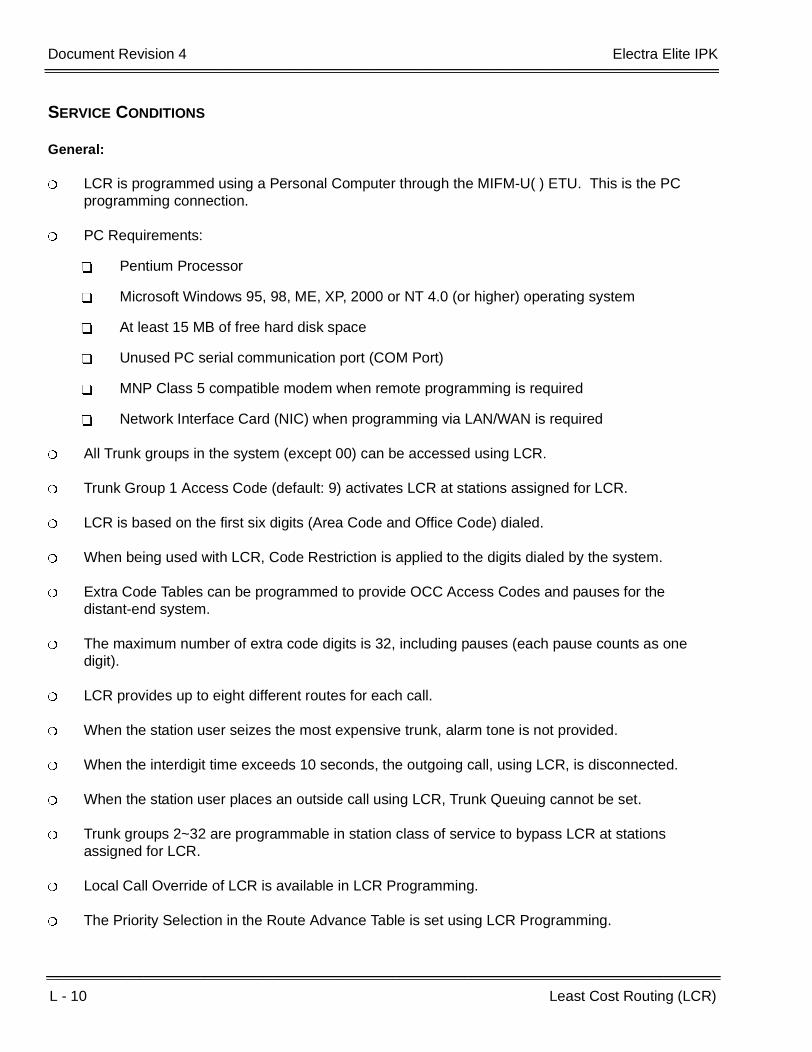
L - 10 Least Cost Routing (LCR)
___________________________________________________________________________________
___________________________________________________________________________________Document Revision 4 Electra Elite IPK
SERVICE CONDITIONS
General:
LCR is programmed using a Personal Computer through the MIFM-U( ) ETU. This is the PC programming connection.
PC Requirements:
Pentium Processor
Microsoft Windows 95, 98, ME, XP, 2000 or NT 4.0 (or higher) operating system
At least 15 MB of free hard disk space
Unused PC serial communication port (COM Port)
MNP Class 5 compatible modem when remote programming is required
Network Interface Card (NIC) when programming via LAN/WAN is required
All Trunk groups in the system (except 00) can be accessed using LCR.
Trunk Group 1 Access Code (default: 9) activates LCR at stations assigned for LCR.
LCR is based on the first six digits (Area Code and Office Code) dialed.
When being used with LCR, Code Restriction is applied to the digits dialed by the system.
Extra Code Tables can be programmed to provide OCC Access Codes and pauses for the distant-end system.
The maximum number of extra code digits is 32, including pauses (each pause counts as one digit).
LCR provides up to eight different routes for each call.
When the station user seizes the most expensive trunk, alarm tone is not provided.
When the interdigit time exceeds 10 seconds, the outgoing call, using LCR, is disconnected.
When the station user places an outside call using LCR, Trunk Queuing cannot be set.
Trunk groups 2~32 are programmable in station class of service to bypass LCR at stations assigned for LCR.
Local Call Override of LCR is available in LCR Programming.
The Priority Selection in the Route Advance Table is set using LCR Programming.

Electra Elite IPK Document Revision 4
Features and Specifications Manual L - 11
___________________________________________________________________________________
___________________________________________________________________________________
The SPE(M)-U( ) ETU is programmed as an MIFM-U( ) ETU.
Restrictions:
Trunk directly assigned on Line Keys bypass LCR.
Route Advance Blocks assigned on a line key bypass LCR.
Memory Block 1-8-08 (Class of Service (Station) Feature Selection 2), LCR/ARS Bypass applies only when the station is assigned to a LCR/ARS Class (1~4) in Memory Block 4-40 (LCR Class Selection).
When the Electra Elite IPK system has KF registration, this feature is not available.
Outgoing calls using DISA cannot access LCR.
When the Elite LAN PC programming device is used, the system can be programmed via the LAN or WAN. Version V4.00 LCR PC software is required.
When the JP5, DFLTS jumper is installed on the MIFM-U20 ETU or Switch SW4-2 on the SPE(M)-U( ) ETU is On, all SMDR, LCR, and Caller ID records are cleared, and the IP address, User Name, Password, and other possible like items are all set to the factory default values.

L - 12 Least Cost Routing (LCR)
___________________________________________________________________________________
___________________________________________________________________________________Document Revision 4 Electra Elite IPK
GUIDE TO FEATURE PROGRAMMING
Orderand
ShortcutSystem Data Name
Memory Block
Function
1-8-07AttendantPage-Line
Key
1-8-08StationPage-
Line Key
+BS Card Interface Slot Assignment 7-1
+BS MIF (LCR) Assignment 7-3-01
+BA Access Code (1-, 2-, or 3-Digit) Assignment 1-1-46/47/48
101
+BTS Class of Service (Station) Feature Selection 2 1-8-08 3-4
+BTT LCR Class Selection 4-40
+BTTStation to Class of Service Feature Assignment
4-17
+BCT Trunk Type Selection 3-91
+BCT Trunk-to-Trunk Group Assignment 3-03
+BITone Assignment 1-8-15 Tone
Table 10
When the system is at default this Memory Block must be programmed for the feature to be used.

Features and Specifications Manual L - 13
___________________________________________________________________________________
___________________________________________________________________________________
Live Monitoring L-4
FEATURE DESCRIPTION
An Electra Elite IPK Multiline Terminal user can listen to voice mail messages as the message is being recorded by the EliteMail VMS/FMS. Live Monitoring is password protected and can be used in automatic or manual mode. When Live Monitoring is in use, the audio is played from the Multiline Terminal Speaker. The terminal user can pick up the handset and speak to the caller anytime during the recording.
EliteMail VMS version Q00631 or higher or an EliteMail FMS version QOS531 or higher are required.
EliteMail ETI supports Live Monitoring ONLY using View Call Plus. It does not support Live Monitoring via telephone.
SYSTEM AVAILABILITY
Terminal Type:
All Multiline Terminals
Required Components:
VMS(2)/(4)/(8)-U( ) ETU
FMS(2)/(4)/(8)-U( ) ETU
CTI(4)/(8)/(12)/(16)-U( ) ETU

L - 14 Live Monitoring
___________________________________________________________________________________
___________________________________________________________________________________Document Revision 4 Electra Elite IPK
OPERATING PROCEDURES
EliteMail FMS/VMS
To enable Live Monitoring:
1. Press the feature access key assigned as Live Monitoring.
2. Dial the password (same as Station Outgoing Lockout password); default isKKKKKKKKKK.
3. Live Monitoring key flashes green while this feature is being set.
To cancel the Live Monitoring Feature when not in use:
Press the Live Monitoring Feature Access key.
To start Manual Live Monitoring while the caller is leaving a voice mail message:
1. Press the Start softkey while the CO caller is leaving a message.
2. Press the Cancel softkey to stop Live Monitoring.
- OR -
Pick up handset to retrieve the call from voice mail.
To start Live Monitoring without display or softkeys using Automatic mode:
The caller is heard through the speaker when the caller receives the beep tone to start recording the message.
To stop Live Monitoring while the caller is leaving a voice mail message in Automatic mode:
Press the Cancel softkey.

Electra Elite IPK Document Revision 4
Features and Specifications Manual L - 15
___________________________________________________________________________________
___________________________________________________________________________________
To stop Live Monitoring without display or softkeys using Automatic mode:
Press the Live Monitoring feature access key.
To retrieve a call during the Live Monitoring Feature:
Pick up the handset.
- OR -
Press E .
EliteMail CTI
Live Monitoring on EliteMail CTI is only supported using View Call Plus. In addition the caller must be routed to the Auto Attendant of the CTI first.
To start manual Live Monitoring while the caller is leaving a message:
1. In View Call Plus application press the Monitor button while the CO caller is leaving a message.
2. Press the Take Call button in View Call Plus to stop Live Monitoring and connect with the caller.
- OR -
Wait until the caller has finished leaving a message.
SERVICE CONDITIONS
General:
Visual indications for Live Monitoring line key LED include the following:
Red flash Setting up Live Monitoring Mode
Red In Live Monitoring Mode (Station is available to receive Live Monitoring)
When the Live Monitoring key is assigned on a One-Touch or Feature Access key, the key toggles Live Monitoring On/Off.
When multiple calls are recording to the same mailbox, user can Live Monitor the first call only.
When you press Feature, Conf, Redial, Speaker, Answer (flashing key), or Line/DSS key (with assigned function), Live Monitoring is canceled, and the key you press is activated.

L - 16 Live Monitoring
___________________________________________________________________________________
___________________________________________________________________________________Document Revision 4 Electra Elite IPK
A Feature Access key must be available to assign to Live Monitoring. Feature code for Live Monitoring is 07.
The EliteMail VMS/FMS must have Live Monitoring set per mailbox for one of the following:
Manual Mode
Automatic Mode
Not Available (Default)
Restrictions:
Live Monitoring is not available for internal calls but is available for the following outside calls:
Calls forwarded to Voice Mail
Calls transferred to Voice Mail
DIT/DID calls to Voice Mail
Manual Mode is available only on terminals with softkeys.
Live Monitoring is not available for the following conditions:
During an internal call to a station
When a station places a conference call on hold
For Voice Mail messages sent to multiple mailboxes
For Voice Mail messages sent to mailboxes that do not correspond to the actual station number.
When DND, Call Forward – All Call, or Station Outgoing Lockout is set during Live Monitoring Mode, Live Monitoring is canceled. When required, a station user must set up Live Monitoring mode after setting Call Forward – All Call.
Live Monitoring call cannot be picked up by Call Pickup feature.
The EliteMail VP does not support live monitoring.
The EliteMail CTI only supports Live Monitor TeLANophy application via view call plus, not via Softkeys, Feature Access or One-Touch keys.
The Live Monitor feature on the EliteMail CTI requires that all incoming calls be answered by the Automated Attendant on the CTI. It also requires the individual mailbox to be set for await answer transfers.
This feature is not available when 5-, 6-, or 7-digit station numbers are used.

Electra Elite IPK Document Revision 4
Features and Specifications Manual L - 17
___________________________________________________________________________________
___________________________________________________________________________________
GUIDE TO FEATURE PROGRAMMING
Orderand
ShortcutSystem Data Name
Memory Block
Function
1-8-07AttendantPage-Line
Key
1-8-08StationPage-
Line Key
+BS Card Interface Slot Assignment 7-1
+BTM Line Key Selection for Telephone Mode 4-12
+BTS Class of Service (Station) Feature Selection 2 1-8-08 5-6
When the system is at default this Memory Block must be programmed for the feature to be used.

L - 18 Live Monitoring
___________________________________________________________________________________
___________________________________________________________________________________Document Revision 4 Electra Elite IPK
THIS PAGE INTENTIONALLY LEFT BLANK

Features and Specifications Manual L - 19
___________________________________________________________________________________
___________________________________________________________________________________
Live Record L-5
FEATURE DESCRIPTION
Live Record simplifies Message and note taking by permitting a portion of the conversation in progress to be recorded automatically or manually.
SYSTEM AVAILABILITY
Terminal Type:
All Multiline Terminals
Required Components:
VMS(2)/(4)/(8)-U( ) ETU
FMS(2)/(4)/(8)-U( ) ETU
CTI(4)/(8)/(12)/(16)-U( ) ETU
OPERATING PROCEDURES
To record an incoming CO/PBX conversation using Automatic Live Record:
1. Go off hook to answer an incoming call. Live Record automatically starts.
2. RECORD is displayed in the lower section of the LCD on the Multiline Terminal.
3. To store the recorded conversation in a different mailbox, dial a mailbox number or press a One-Touch key or Feature Access key programmed with the mailbox number.
4. RECORD XXXXXX is displayed in the lower section of the LCD on the Multiline Terminal (XXXXXX is the station name/number where the conversation is stored).
L - 20 Live Record
___________________________________________________________________________________
___________________________________________________________________________________Document Revision 4 Electra Elite IPK
To record an incoming CO/PBX conversation using Manual Live Record:
1. Press the Feature Access key programmed as the record key. The Record key flashes red when Live Record begins and flashes green when Live Record is addressed.
2. RECORD is displayed in the lower section of the LCD on the Multiline Terminal.
3. To store the recorded conversation in a different mailbox, dial a mailbox number or press a One-Touch key or Feature Access key programmed with the mailbox number.
4. RECORD XXXXXX is displayed in the lower section of the LCD on the Multiline Terminal (XXXXXX is the station name/number where the conversation is stored.
CAUTION
Using the Live Record feature to eavesdrop or record sound activities at the other end of the telephoneline may be illegal under certain circumstances and laws. Consult a legal advisor before implementingany practice to monitor or record a telephone conversation. Some federal and state laws require a partymonitoring or recording a telephone conversation to use a beep-tone(s), notify all parties to thetelephone conversation, and/or obtain consent of all parties to the telephone conversation. To monitor orrecord sound activities at the other end of the telephone line using the Live Record feature, the sound ofthe alert tone at the beginning of Live Record may or may not be considered sufficient under applicablelaws. Some applicable laws provide for strict penalties for illegal monitoring or recording of telephoneconversations.
General:
Tone Override, Call Alert, Barge-In, Camp-On, and Voice Over Split feature tones are denied during Live Record.
When a Multiline Terminal user completes Live Record without specifying a mailbox where the conversation should be stored and Automatic Recall is not assigned in Digital Voice Mail programming, the conversation is stored in the mailbox assigned to the Multiline Terminal. When a Multiline Terminal user completes Live Record without specifying a mailbox where the conversation should be stored and Automatic Recall is assigned in Digital Voice Mail programming, the conversation is stored in the mailbox assigned to the Multiline Terminal and the system recalls the Multiline Terminal and plays the recorded conversation.
(Auto Callback rings - 4 times, Waiting Time - 3 minute, Redial - 5 times.)
Live Record can be used only from Multiline Terminals.
Individual trunks must be assigned for the Live Record feature to operate.
Electra Elite IPK Document Revision 4
Features and Specifications Manual L - 21
___________________________________________________________________________________
___________________________________________________________________________________
The system can be programmed to allow/deny an alert tone for Live Record. The 0.5 second alert tone is heard by both the outside party and the Multiline Terminal user when the recording starts or at specified intervals during recording. The interval between alert tones is assigned in the Digital Voice Mail System Programming.
Up to seven feature keys can be programmed for use with Live Record. These feature keys can be assigned to Feature Access keys, One-Touch keys, or DSS keys (on a DSS/BLF console). When the feature keys are assigned to One-Touch keys, no LED indications are provided.
The following feature keys can be programmed:
Record Key
Use this key to manually start Live Record. The associated LED flashes red while recording. Theassociated LED goes off when recording ends or a pause occurs and flashes green when a liverecord message is addressed.
Pause Key
Use this key to pause and restart live record. The associated LED flashes green when recordinghas paused.
Erase Key
Use this key to erase the Live Record conversations. After the Erase key is pressed, the Voice Mailport remains off-hook until the call is terminated.
End Key
Use this key to end the Live Record. The conversation continues without being recorded.
Rerecord Key
Use this key to erase a recorded conversation while recording is in progress and start a newrecording.
Urgent Page Key
Use this key to change the Live Record assignment from dial out to pager. (Message Notificationto Pager Assignment cycles ON/OFF when this key is pressed while recording.)
Address Key
Use this key to confirm Live Record, erase Live Record, change the mailbox number where LiveRecord is stored, or add a recorded prelude to a recorded conversation.
During each Live Record, a conference circuit and Voice Mail Port are used.
Live Record is not allowed when all Add-On Conference circuits are busy.
Additional internal parties cannot be added to a live record conversation during conferencing.
Only CO/PBX, Tie, and DID calls can be recorded using Live Record. Internal calls cannot be recorded using Live Record.
L - 22 Live Record
___________________________________________________________________________________
___________________________________________________________________________________Document Revision 4 Electra Elite IPK
The Record key LED is on when all conference circuits or all Digital Voice Mail ports are busy.
Any station user can direct a live record message to another station user.
Any Multiline Terminal can change the Message Notification mode to Pager Notification mode by first directing a live record message to another station and then pressing the Urgent Page key. The station that is put into the Urgent Page mode must have a pager telephone number assigned.
When a Multiline Terminal (with LCD) is in Pager Notification mode, is displayed in the far right corner of the lower LCD.
Live Record is not allowed on conference calls.
Refer to Feature D-8 (Digital Voice Mail) for more information.
Features and Specifications Manual L - 23
___________________________________________________________________________________
___________________________________________________________________________________
Loop Start Trunks L-6
FEATURE DESCRIPTION
Loop Start Trunks can be connected to the Electra Elite IPK system. Loop Start is assigned per trunk at the associated ETU. Ground Start and Loop Start Trunks can be mixed in the system per trunk. The COI(4)-U( ), COIB(4)-U20, and COIB(8)-U( ) ETU are Loop Start only.
SYSTEM AVAILABILITY
Terminal Type:
Not applicable
Required Components:
COI(8)-U( ), COI(4)-U( ), COIB(4)-U( ), or COIB(8)-U( ) ETU
OPERATING PROCEDURES
None

L - 24 Loop Start Trunks
___________________________________________________________________________________
___________________________________________________________________________________Document Revision 4 Electra Elite IPK
SERVICE CONDITIONS
General:
Each COI(8)-U( ) ETU has eight switches (one for each port) that can be used to select either Loop or Ground Start per trunk.
Each COIB(4)-U10 ETU has four switches (one for each port) that can be used to select either Loop or Ground Start per trunk.
Each COI(4)-U( ), COIB(4)-U20, or COIB(8)-U( ) ETU supports loop start only.
When the serving CO sends a disconnect signal after the outside party abandons a call, the trunk is automatically released.
Sixty-four trunks (Ground Start, Loop Start, ISDN, E&M Tie Lines, and DID Trunks) can be installed in an Expanded Port Package, or 16 trunks, in a Basic Port Package.
GUIDE TO FEATURE PROGRAMMING
Orderand
ShortcutSystem Data Name
Memory Block
Function
1-8-07AttendantPage-Line
Key
1-8-08StationPage-
Line Key
+BS Card Interface Slot Assignment 7-1

Features and Specifications Manual M - 1
___________________________________________________________________________________
___________________________________________________________________________________
Message Display Board M-1
FEATURE DESCRIPTION
The Message display Board indicates voice mail messages left for those without telephones. Message Display Boards include a basic board and expansion boards. Each basic and expansion board provides up to eight messages.
SYSTEM AVAILABILITY
Terminal Type:
Not Applicable
Required Components:
DBM(B)-U( ) Box
DBM(E)-U( ) Box
OPERATING PROCEDURES
None
SERVICE CONDITIONS
General:
The DBM(B)-U( ) Box is the Basic Message Display Board that is connected to an ESI port and provides eight large LEDs to indicate up to eight voice mail messages. The provided AC adapter is required to provide power for this board.
Only the DBM(B)-U( ) requires an ESI port and AC adapter.
A maximum of 384 LEDs can be assigned to the Message Display Boards, but only 200 mail boxes can be indicated.
When a voice mail message is left for someone, the corresponding large lamp on the board is on.
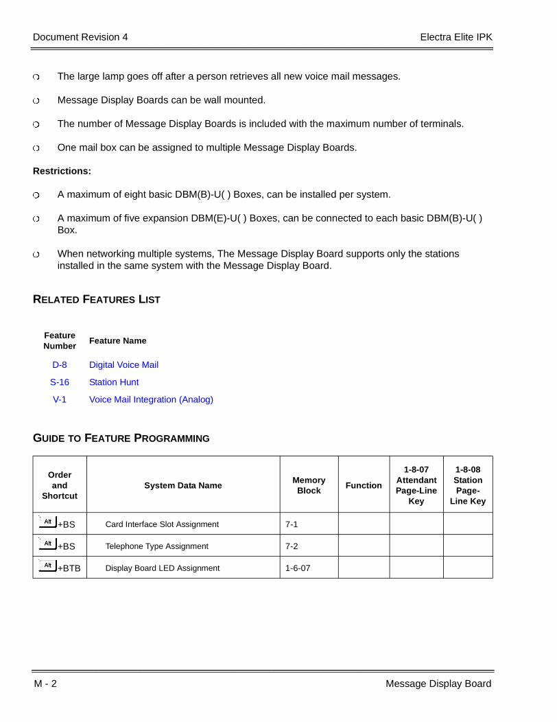
M - 2 Message Display Board
___________________________________________________________________________________
___________________________________________________________________________________Document Revision 4 Electra Elite IPK
The large lamp goes off after a person retrieves all new voice mail messages.
Message Display Boards can be wall mounted.
The number of Message Display Boards is included with the maximum number of terminals.
One mail box can be assigned to multiple Message Display Boards.
Restrictions:
A maximum of eight basic DBM(B)-U( ) Boxes, can be installed per system.
A maximum of five expansion DBM(E)-U( ) Boxes, can be connected to each basic DBM(B)-U( ) Box.
When networking multiple systems, The Message Display Board supports only the stations installed in the same system with the Message Display Board.
RELATED FEATURES LIST
GUIDE TO FEATURE PROGRAMMING
Feature Number
Feature Name
D-8 Digital Voice Mail
S-16 Station Hunt
V-1 Voice Mail Integration (Analog)
Orderand
ShortcutSystem Data Name
Memory Block
Function
1-8-07AttendantPage-Line
Key
1-8-08StationPage-
Line Key
+BS Card Interface Slot Assignment 7-1
+BS Telephone Type Assignment 7-2
+BTB Display Board LED Assignment 1-6-07
Features and Specifications Manual M - 3
___________________________________________________________________________________
___________________________________________________________________________________
Message Waiting M-2
FEATURE DESCRIPTION
Message Waiting is set from the Attendant Add-On Console or from a Voice Mail Unit to allow the large LED to provide a distinctive message indication to the station. The station user is alerted to contact the Attendant or Voice Mail Unit for the message.
SYSTEM AVAILABILITY
Terminal Type:
All Multiline Terminals that are assigned on the Attendant Add-On Console, except Single Line Telephones supported by an SLT Adapter.
Required Components:
DCU/DCR-60-1 Console for Attendant Message Waiting
ACA-U/AC-R Unit (AC Adapter)
Voice Mail Unit for Voice Mail Message Waiting
OPERATING PROCEDURES
To set a Message at the Attendant Position using the Attendant Add-On Console:
1. Press the Message key on the Attendant Add-On Console.
2. Press the DSS key on the Attendant Add-On Console that is associated with the station where Message Waiting indication is to be set.

M - 4 Message Waiting
___________________________________________________________________________________
___________________________________________________________________________________Document Revision 4 Electra Elite IPK
To cancel a Message at the Attendant Position using the Attendant Add-On Console:
1. Press the Message key on the Attendant Add-On Console.
2. Press the DSS key on the Attendant Add-On Console that is associated with the station where Message Waiting is to be canceled.
To respond to Message Waiting indication:
Dial K or the associated Attendant station with the Attendant Add-On Console used to set the message.
- OR -
Call the Voice Mail System, and retrieve the messages.
SERVICE CONDITIONS
General:
A Message Waiting indication is provided on the large LED on the recipient Multiline Terminal. Message Waiting indications from the Attendant Add-On Console flash green; indications from a Voice Mail Unit flash red.
To confirm a Message Waiting indication at an Attendant Add-On Console, ensure that the green LED associated with the station is on. A Message Waiting indication remains on until the message is canceled at the Attendant Add-On Console where it was set.
When two or more (maximum of four per system) Attendant Add-On Consoles are installed, the message is displayed only on the Attendant Add-On Console where the setting was made.
All Attendant Add-On Consoles can be used to set a Message Waiting to the same station.
Single Line Telephones supported by an SLI(8)-U( ) ETU with a Message Waiting LED receive a flashing Message Waiting indication when set.
A Voice Mail system can be used to set and cancel the messages to stations.
Message Waiting from an Attendant Add-On Console has higher priority than Message Waiting from a Voice Mail Unit.
An Attendant Add-On Console with a Message Waiting key assigned on it cannot be used to set the Attendant Station Outgoing Lockout feature.
Message Waiting status is retained in memory by the memory backup battery.
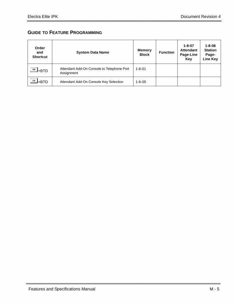
Electra Elite IPK Document Revision 4
Features and Specifications Manual M - 5
___________________________________________________________________________________
___________________________________________________________________________________
GUIDE TO FEATURE PROGRAMMING
Orderand
ShortcutSystem Data Name
Memory Block
Function
1-8-07AttendantPage-Line
Key
1-8-08StationPage-
Line Key
+BTDAttendant Add-On Console to Telephone Port Assignment
1-6-01
+BTD Attendant Add-On Console Key Selection 1-6-05

M - 6 Message Waiting
___________________________________________________________________________________
___________________________________________________________________________________Document Revision 4 Electra Elite IPK
THIS PAGE INTENTIONALLY LEFT BLANK
Features and Specifications Manual M - 7
___________________________________________________________________________________
___________________________________________________________________________________
Microphone Control M-3
FEATURE DESCRIPTION
Microphone Control allows ON/OFF status indication on all Multiline Terminals. A Flexible Line key or One-Touch key programmed for Microphone Control or an Access Code is used to mute the microphone for privacy during incoming voice announcement calls and during calls using the built-in speakerphone.
SYSTEM AVAILABILITY
Terminal Type:
All Multiline Terminals
Required Components:
None
OPERATING PROCEDURES
When the MIC ON/OFF feature is assigned on Feature Access key or a One-Touch key on a Flexible Line key:
1. When the MIC LED is off, press the MIC key to turn the MIC LED on and to activate the microphone.
2. When the MIC LED is on, press the MIC key to turn the MIC LED off and to deactivate the microphone.

M - 8 Microphone Control
___________________________________________________________________________________
___________________________________________________________________________________Document Revision 4 Electra Elite IPK
When the terminal does not have a dedicated MIC key and when the MIC ON/OFF feature is not assigned on a Feature Access key or a One-Touch key:
When the MIC LED is off:
1. Press A .
2. Dial Access Code A.
3. The MIC LED comes on.
When the MIC LED is on:
1. Press A .
2. Dial Access Code A.
3. The MIC LED goes off.
SERVICE CONDITIONS
General:
DTH/DTR Multiline Terminals have a built-in MIC key.
The MIC key controls the built-in microphone during speakerphone mode and controls the handset mute feature during handset/headset operation.
The microphone is activated when the MIC LED is on, and an internal voice signal call is made to a Multiline Terminal.
When full handsfree is denied in System Programming, Handsfree Dialing/Monitoring does not activate the microphone.
The microphone status is indicated by the LED labeled MIC (not the Flexible Line key, when assigned). When the MIC LED is on, the microphone is on.
RELATED FEATURES LIST
Feature Number
Feature Name
F-8 Full Handsfree Operation
H-1 Handset Mute
H-2 Handsfree Answerback

Electra Elite IPK Document Revision 4
Features and Specifications Manual M - 9
___________________________________________________________________________________
___________________________________________________________________________________
GUIDE TO FEATURE PROGRAMMING
Orderand
ShortcutSystem Data Name
Memory Block
Function
1-8-07AttendantPage-Line
Key
1-8-08StationPage-
Line Key
+BTM Line Key Selection for Telephone Mode 4-12

M - 10 Microphone Control
___________________________________________________________________________________
___________________________________________________________________________________Document Revision 4 Electra Elite IPK
THIS PAGE INTENTIONALLY LEFT BLANK
Features and Specifications Manual M - 11
___________________________________________________________________________________
___________________________________________________________________________________
Multiline Conference Bridge M-4
FEATURE DESCRIPTION
Multiline Conference Bridge allows any intercom or outside caller to call the CNF(8)-U( ) ETU to place a multiparty conference call. Each CNF(8)-U( ) ETU supports one 8-party conference or two 4-party conferences regulated by a switch setting. Two CNF(8)-U( ) ETUs may be installed. DSP based amplification provides a higher quality conference call.
SYSTEM AVAILABILITY
Terminal Type:
All Stations
Required Components:
CNF(8)-U( ) ETU
SETUP PROCEDURES
To set the Supervisor Password:
1. Call the Conference Bridge extension number, and wait for the voice prompt.
2. Dial the default Supervisor Password (KKKK), then dial L.
3. Follow the voice prompt, and enter the setting verification mode (L). Then enter system set mode.
4. Follow the voice prompt to change Supervisor Password (4~8 digits).
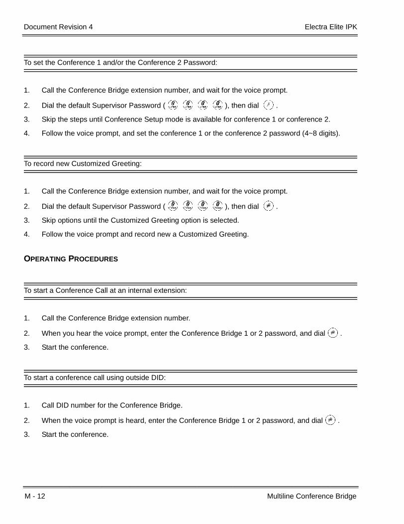
M - 12 Multiline Conference Bridge
___________________________________________________________________________________
___________________________________________________________________________________Document Revision 4 Electra Elite IPK
To set the Conference 1 and/or the Conference 2 Password:
1. Call the Conference Bridge extension number, and wait for the voice prompt.
2. Dial the default Supervisor Password (KKKK), then dial L.
3. Skip the steps until Conference Setup mode is available for conference 1 or conference 2.
4. Follow the voice prompt, and set the conference 1 or the conference 2 password (4~8 digits).
To record new Customized Greeting:
1. Call the Conference Bridge extension number, and wait for the voice prompt.
2. Dial the default Supervisor Password (KKKK), then dial L.
3. Skip options until the Customized Greeting option is selected.
4. Follow the voice prompt and record new a Customized Greeting.
OPERATING PROCEDURES
To start a Conference Call at an internal extension:
1. Call the Conference Bridge extension number.
2. When you hear the voice prompt, enter the Conference Bridge 1 or 2 password, and dialL.
3. Start the conference.
To start a conference call using outside DID:
1. Call DID number for the Conference Bridge.
2. When the voice prompt is heard, enter the Conference Bridge 1 or 2 password, and dialL.
3. Start the conference.

Electra Elite IPK Document Revision 4
Features and Specifications Manual M - 13
___________________________________________________________________________________
___________________________________________________________________________________
To start a conference call using outside DIT:
1. Call a trunk that is set as DIT to Conference Bridge.
2. When the voice prompt is heard, enter the Conference Bridge 1 or 2 password, and dialL.
3. Start the conference.
To start a conference call on an incoming CO call using an Automated Attendant:
1. Call a trunk that is set as an Automated Attendant.
2. Select the option for an extension connected to the Conference Bridge.
3. When the voice prompt is heard, enter the Conference Bridge 1 or 2 password, and dialL.
4. Start the conference.
To start a conference call from an incoming CO call using an Attendant:
1. Call the Attendant, and ask to be transferred to an extension connected to the Conference Bridge.
2. When the voice prompt is heard, enter the Conference Bridge 1 or 2 password, and dialL.
3. Start the conference.
SERVICE CONDITIONS
General:
The CNF(8)-U( ) ETU can be used with any version of software on the Electra Elite IPK system.
When CNF is set for two, four-party conferences, ports 1~4 can be set to the same Master Hunt Group, and ports 5~8 can be set to a different Master Hunt Group using Memory Blocks 4-14 (Intercom Master Hunt Number Selection) and 4-15 (Intercom Master Hunt Number Forward Assignment). This allows two different Pilot Numbers for each conference.
- OR -
If only one Pilot number is needed, put all eight ports in one hunt group using Memory Block 4-15(Intercom Master Hunt Number Forward Assignment). When the password is entered, theconference selected is the conference you enter.

M - 14 Multiline Conference Bridge
___________________________________________________________________________________
___________________________________________________________________________________Document Revision 4 Electra Elite IPK
Restrictions:
The supervisor must perform the Setting Procedures before the conference Bridge can be used.
Up to 16 analog Voice Mail ports are available. The CNF(8)-U( ) ETU reduces this number by eight.
Each CNF(8)-U( ) ETU reduces the number of stations, wireless stations, and CAR keys by eight.
GUIDE TO FEATURE PROGRAMMING
Orderand
ShortcutSystem Data Name
Memory Block
Function
1-8-07AttendantPage-Line
Key
1-8-08StationPage-
Line Key
+BS Card Interface Slot Assignment 7-1
+BTI Voice Mail/SLT Selection 4-35
+BS Station Number Assignment 4-10
+BTT Intercom Master Hunt Number Selection 4-14
+BTT Intercom Master Hunt Number Forward Assignment
4-15
+BTT Station Name Assignment 4-18
+BCT DIT Assignment 3-42
+BCT ANA Assignment 3-43
When the system is at default this Memory Block must be programmed for the feature to be used.

Features and Specifications Manual M - 15
___________________________________________________________________________________
___________________________________________________________________________________
Multilingual LCD Indication M-5
FEATURE DESCRIPTION
Multilingual LCD Indication provides the option for English, French, Japanese, or Spanish characters on Multiline Terminals with an LCD. Language selection is made per station using System Programming.
ENHANCEMENT(S)
Release 3000
With R3000 or higher, Multilingual LCD indication supports the following multilingual Clock/Calender display:
SYSTEM AVAILABILITY
Terminal Type:
Multiline Terminals with LCD
Required Components:
None
OPERATING PROCEDURES
None
SERVICE CONDITIONS
General:
Multilingual Indication per station only applies for fixed LCD messages.
Programmable messages (station name or Customized Messages) are programmed per message.
English SUN MON TUE WED THU FRI SAT
Japanese SUN MON TUE WED THU FRI SAT
French DIM LUN MAR MER JEU VEN SAM
Spanish DOM LUN MAR MIE JUE VIE SAB

M - 16 Multilingual LCD Indication
___________________________________________________________________________________
___________________________________________________________________________________Document Revision 4 Electra Elite IPK
Restrictions:
Language changes for softkeys do not take affect on the DTH/DTR or DTU/DTP terminal until the power to the terminal is shut off and then restored.
The LCD of the Electra Elite IPK Terminal provides a volume bar indication, while adjusting the following volume levels or controls:
Speaker Volume
Handset/Headset Volume
BGM Volume
Ring Volume/Off Hook Ring Volume
LCD Contrast
Only English displays are provided (SPEAKER, HANDSET, RING, LCD).
RELATED FEATURE LIST
GUIDE TO FEATURE PROGRAMMING
Feature Number
Feature Name
C-20 Clock/Calendar Display
C-27 Customized Message
I-3 Incoming Trunk Name or Number Display
S-4 Seized Trunk Name/Number Display
Orderand
ShortcutSystem Data Name
Memory Block
Function
1-8-07AttendantPage-Line
Key
1-8-08StationPage-
Line Key
+BTM Multilingual LCD Indication Selection 4-28
+BTT Station Name Assignment 4-18
+BI Customized Message 1~10 Assignment 1-2-09 ~ 18
When the system is at default this Memory Block must be programmed for the feature to be used.

Features and Specifications Manual M - 17
___________________________________________________________________________________
___________________________________________________________________________________
Multiple Trunk Groups M-6
FEATURE DESCRIPTION
A maximum of 32 Trunk groups may be assigned. Each group can have a separate Trunk Group Access Code. Assigning Trunk groups provides access to different outside trunks. With Tenant Service, different tenants can be programmed to access only their Trunk group.
SYSTEM AVAILABILITY
Terminal Type:
Not Applicable
Required Components:
None
OPERATING PROCEDURES
To use this feature at any station:
1. Lift the handset, and wait for internal dial tone.
2. Dial the Trunk Group Access Code.
3. Wait for outside dial tone.
4. Dial the desired telephone number.
SERVICE CONDITIONS
General:
Dial Access is provided only on Multifunction registered systems.

M - 18 Multiple Trunk Groups
___________________________________________________________________________________
___________________________________________________________________________________Document Revision 4 Electra Elite IPK
At default, CO/PBX lines 01~ 08 are assigned in Trunk Group 1, all Tie lines are assigned in Trunk group 2, and no additional CO/PBX lines or DID lines are assigned to a Trunk group.
The system provides for 32 Trunk groups.
Trunks can be assigned to any or all Tenant groups.
Various features such as Code Restriction (outgoing), LCR, and Route Advance Block are based on Trunk groups.
Trunk groups can be assigned to a Flexible Line key as a Pooled Line (outgoing).
Default Trunk Access Codes include the following:
Dial 9 Trunk Group 1
Dial 8 Trunk Group 2
Dial 70 Trunk Group 3
Dial 71 Trunk Group 4
Dial 72 Trunk Group 5
Dial 73 Trunk Group 6
Dial 74 Trunk Group 7
Dial 75 Trunk Group 8
Restrictions:
A trunk can be assigned to only one Trunk group.
GUIDE TO FEATURE PROGRAMMING
Orderand
ShortcutSystem Data Name
Memory Block
Function
1-8-07AttendantPage-Line
Key
1-8-08StationPage-
Line Key
+BCT Trunk-to-Trunk Group Assignment 3-03
+BAAccess Code (1-, 2-, or 3-Digit) Assignment 1-1-46/47/
48101 ~ 132
Features and Specifications Manual M - 19
___________________________________________________________________________________
___________________________________________________________________________________
Music on Hold M-7
FEATURE DESCRIPTION
A locally provided external music source or an internal music source can be used to supply music to parties on hold, to assure them that they are still connected to the system.
System Software allows CO ports to provide multiple music sources to different COs in the system.
SYSTEM AVAILABILITY
Terminal Type:
Not applicable
Required Components:
External source connected to the RCA jack on the basic B64-U( ) KSU.
OPERATING PROCEDURES
None
SERVICE CONDITIONS
General:
Music On Hold (MOH) is provided for all outside and internal calls on hold.
Music On Hold can be disabled when required.
Use Memory Block 4-66 (MOH or Ring Back Tone Selection) to assign MOH or Ring Back Tone for the outside party when a trunk call is placed on hold by the Transfer key on a Dterm, or hook flash from a Single Line Telephone, or the Transfer or Hold keys at a PSII station.
Music On Hold is provided using the built-in tone melodies or an external source connected to the RCA jack on the basic B64-U( ) KSU.

M - 20 Music on Hold
___________________________________________________________________________________
___________________________________________________________________________________Document Revision 4 Electra Elite IPK
Internal Source:
Program one of two melodies (American Folk Song melody, or Christmas Song melody) as aninternal source. A volume control for the built-in MOH source can also be programmed.
External Source:
Music source (radio, tape player, or CD) must be provided locally.
Source output levels should be less than 0.6 RMS signal level with 600 Ω impedance.
Optional interface ETUs are not required for this feature.
A CO line that is assigned as a CO external music on hold source cannot be seized, even when the CO trunk is assigned on a line key of a Multiline terminal.
A CO line that is assigned to a CO external music of hold source is skipped without being seized, even when that CO is assigned to a trunk group.
When Memory Block 3-11 (CO External Source Selection) contradicts Memory Block 3-12 (Trunk-to-MOH Trunk Assignment) MOH works according to the Memory Block 1-8-31 (Hold Tone Source Assignment) setting.
Use Memory Block 3-11 (CO External Source Selection) to specify whether the MOH source is from the CO (default) or an EXT SOURCE. Unused circuits on a COI/COID ETU can be assigned as MOH inputs.
Use Memory Block 3-12, (Trunk-to-MOH Trunk Assignment) to assign the external music source to each trunk.
Example:
Trunks 09 and 10 are assigned as external sources. Trunk 09 is programmed as the externalsource for Trunks 01~05 when a call is placed on hold. Trunk 10 is programmed as the externalsource for Trunks 06~08 when a call is placed on hold.
The Internal Music on Hold source for CPUI( )-U20 and CPUI( )-U10 ETUs Lot 3XXX or higher provides the following options in Memory Block 1-8-09 (Music on Hold Pattern Selection):
LK1 (Option A): Hold Tone (default)
LK2 (Option B) American Folk Song Medley

Electra Elite IPK Document Revision 4
Features and Specifications Manual M - 21
___________________________________________________________________________________
___________________________________________________________________________________
RELATED FEATURE LIST
GUIDE TO FEATURE PROGRAMMING
Feature Number
Feature Name
A-8 Answer Hold
A-15 Attendant Transfer
A-22 Automatic Hold
H-5 Hold With Recall (Exclusive and Non-Exclusive)
S-21 Station Transfer
Orderand
ShortcutSystem Data Name
Memory Block
Function
1-8-07AttendantPage-Line
Key
1-8-08StationPage-
Line Key
+AUAutomated Attendant Delay Announcement Hold Tone section
1-4-17
+BCS Music on Hold Pattern Selection 1-8-09
+BCS Hold Tone Source Assignment 1-8-31
+BCS Hold Internal Tone Volume Selection 1-8-32
+BCT CO External Source Selection 3-11
+BCT CO External Hold Memory Selection 3-12
+BTT MOH or Ring Back Tone Selection 4-66

M - 22 Music on Hold
___________________________________________________________________________________
___________________________________________________________________________________Document Revision 4 Electra Elite IPK
THIS PAGE INTENTIONALLY LEFT BLANK

Features and Specifications Manual N - 1
___________________________________________________________________________________
___________________________________________________________________________________
NEC Elite PC Assistant N-1
FEATURE DESCRIPTION
The NEC Elite PC Assistant provides a desktop application to allow basic telephone functionality through a software interface. This feature uses the CT(U)-R/CT(A)-R Adapter as the TAPI device for the application to control the user telephone. Using this application, the user can easily manage call handling tasks without switching attention between the telephone and the PC. Advanced features such as recording ability, E-mail integration, and personal greeting available with the Professional version provide additional assistance to meet the industry need for this product. The NEC Elite PC Assistant has three main components:
NEC Elite PC Assistance software
This application runs on a PC and provides the PC-based GUI (Graphical User Interface) andfeatures.
CT(U)-R/CT(A)-R Adapter
This adapter is installed on the Multiline Terminal and interfaces the Electra Elite IPK with the USB(Universal Serial Bus) port or an available Serial port on the PC.
Headset (Optional)
A headset can be plugged into the Multiline Terminal and used when making or receiving calls withthe NEC Elite PC Assistant.
The NEC Elite PC Assistant runs on a PC and communicates with the Electra Elite IPK through a normal digital station port using the CT(U)-R/CT(A)-R Adapter attached to the telephone. When a call comes into this station it is displayed on the PC and provides several features that allow the user to handle the call quickly. The NEC Elite PC Assistant can be minimized to run in the background and pop to the front when call activity occurs. Calls can be handled with the keyboard or the mouse. The user speaks to a caller through the handset, headset, or speakerphone of the Multiline Terminal the application is running on.
The following sections define the basic operation and look and feel of the NEC Elite PC Assistant.
Personal Directory
Because the NEC Elite PC Assistant can integrate with Outlook, each separate user can establish a personal directory.

N - 2 NEC Elite PC Assistant
___________________________________________________________________________________
___________________________________________________________________________________Document Revision 4 Electra Elite IPK
Call Log
The Call Log is similar to that of the PC Console applications. An inbound or outbound indicator is in the left most column followed by a telephone number dialed or received. When there is a name in the CLID information on an inbound call, it is included in that same column. On outbound calls, when a directory entry is selected, that name is displayed.
Busy Line Key Indicators
The busy line indicators are located below the number in each field and appear when the telephone is taken off hook to originate or answer a call. A green indicator means the line is active. When the call is placed on hold, the indicator turns yellow. When an inbound call is ringing, the indicator is red. When the call is terminated, there is no line status indicator.
UP to eight line key indicators can be displayed at the same time. When the mouse is placed on top of a line indicator, the display for that line is shown. This could help when multiple calls are on hold and the user needs to confirm which line is linked to a specific caller.
Supported KTS Features
The following KTS features have corresponding icons that can be placed on the Control Bar. At a minimum, features visible by default are indicated.
Automatic Redial
Background Music
Barge-In
Call Pickup Direct
Call Pickup Group
Conference (default)
DND
Forward (default)
Night Call Pickup
Page (default)
Park (default)
Transfer (default)
UnPark (default)
Voice Over Split

Electra Elite IPK Document Revision 4
Features and Specifications Manual N - 3
___________________________________________________________________________________
___________________________________________________________________________________
In addition to these feature keys, a Dial/Hang UP icon (telephone) controls the hook state and a Hold key that are always on the Control Bar. When too many keys are selected for display on the Control Bar, the UI expands and a second row of icons is displayed under the top row.
Certain KTS features like Transfer, Conference, or Park, require additional information and control. When one of these features is initiated by pressing the icon while a call is active, a separate control box with the necessary commands or keys to join the callers or complete the call park operation is displayed.
Recording
A Record key (Professional Version) is a default key on the application. When this Record key is pressed, the icon transitions to a Stop Record key. Recording continues until the call has ended or the Stop Record key is pressed. When a call is recorded, a tape icon is displayed in the call log next to the call record. When a Hold key is pressed during a recorded conversation, the white (empty) space is not recorded.
Outlook Integration
The NEC Elite PC Assistant (Professional Version) can integrate with Microsoft Outlook. When this option is enabled, and an inbound call is received with an associated number that matches an entry in the Outlook database, the Outlook window for that user is automatically displayed.
An option is also provided in preferences to allow a contact window to popup when a call is received from outside the KTS. This allows a user to ignore Outlook popup on internal calls.
SYSTEM AVAILABILITY
Supported Electra Elite/IPK Firmware:
Electra Elite IPK: R1000 or higher
Terminal Type:
Electra Elite IPK Multiline Terminals
Required Components:
Standard Package
CT(U)-R or CT(A)-R Unit for DTH/DTR Multiline Terminals
AC-2/3 Unit for the CT(U)-R or CT(A)-R Unit
Professional Package
CT(U)-R Unit for DTH/DTR Multiline Terminals
AC-2/3 Unit for the CT(U)-R Unit
N - 4 NEC Elite PC Assistant
___________________________________________________________________________________
___________________________________________________________________________________Document Revision 4 Electra Elite IPK
PC Requirements for NEC Elite PC Assistant
Software Requirements
Windows 98 SE, Windows 2000, Windows ME, or Windows XP Professional
Hardware Requirements
Pentium class machine with 500MHz minimum speed
256 MB RAM (minimum)
10 MB available disk space (38 MB additional when .NET framework is not already installed)
CD-ROM Drive
Mouse
Available USB/Serial Port
MAPI compliant e-mail application (required for e-mail features of the NEC Elite PC Assistant)
Optional PC speakers and microphone
Printer (required for NEC Elite PC Assistant printing features)
OPERATING PROCEDURES
Refer to the online help for configuration information.
SERVICE CONDITIONS
General:
The NEC Elite PC Assistant application resides on each individual PC; therefore, each PC must be configured separately.
When line keys on the Multiline Terminal do not match those of NEC Elite PC Assistant, the line keys can be changed in the NEC Elite PC Assistant by looking in File/Telephony/Telephony Configuration/Button Config.
A check of the button mapping on the Multiline Terminal can be performed by looking in File/Telephony/Check Button Mapping. Anytime Memory Block 4-12 (Line Key Selection for Telephone Mode) has been changed for the NEC Elite PC Assistant Multiline Terminal, this check must be performed.

Electra Elite IPK Document Revision 4
Features and Specifications Manual N - 5
___________________________________________________________________________________
___________________________________________________________________________________
Advanced features (recording ability, e-mail integration, and personal greeting) are available only in the Professional Package.
For Call Park to work, Memory Block 1-8-51 (Call Park Selection) should be set to LK1 to support 10 park locations (R4000 or higher)
Restrictions:
Only eight line key indicators can be displayed at one time with the NEC Elite PC Assistant application.
The NEC Elite PC Assistant and ACD using the MIFA-U( ) ETU are not supported simultaneously from the same Multiline Terminal.
When installing the TAPI driver on the NEC Elite PC Assistant, always select 32/32D telephones no matter what model is actually used.
For Auto Headset Seize to work, a Feature Access Key must be programmed in Memory Block 4-12 (Line Key Selection for Telephone Mode) on the NEC Elite PC Assistant telephone, and the application must be set to find that key in File/Telephony/Telephony Configuration/Operation Mode.
The CT(U)-R Unit is required when using the voice functions associated with the Professional Package. The CT(A)-R Unit does not support voice functions.
In a CCIS network, multiple extension lengths are not supported by this application.
When 5, 6, or 7-digit station numbers are used, this feature is not available.
Currently, the DTH-16LD terminal is not supported when using the Elite PC Assistant to program Speed Dial or DSS/BLF keys.

N - 6 NEC Elite PC Assistant
___________________________________________________________________________________
___________________________________________________________________________________Document Revision 4 Electra Elite IPK
GUIDE TO FEATURE PROGRAMMING
Orderand
ShortcutSystem Data Name
Memory Block
Function
1-8-07AttendantPage-Line
Key
1-8-08StationPage-
Line Key
+BS Card Interface Slot Assignment 7-1
+BS Telephone Type Assignment 7-2
+BA Access Code (1-, 2-, 3-Digit) Assignment 1-1-46 ~48
+BTS Class of Service (Station) Feature Selection 2 1-8-08 7-3
+BCT DIT Assignment 3-42
+BCT ANA Assignment 3-43
+BTT CO/PBX Ring Assignment (Day Mode) 4-01
+BTT CO/PBX Ring Assignment (Night Mode) 4-02
+BS Station Number Assignment 4-10
+BTM Line Key selection for Telephone Mode 4-12
When the system is at default this Memory Block must be programmed for the feature to be used.
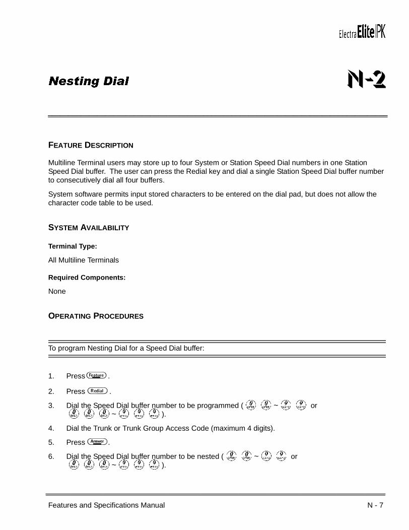
Features and Specifications Manual N - 7
___________________________________________________________________________________
___________________________________________________________________________________
Nesting Dial N-2
FEATURE DESCRIPTION
Multiline Terminal users may store up to four System or Station Speed Dial numbers in one Station Speed Dial buffer. The user can press the Redial key and dial a single Station Speed Dial buffer number to consecutively dial all four buffers.
System software permits input stored characters to be entered on the dial pad, but does not allow the character code table to be used.
SYSTEM AVAILABILITY
Terminal Type:
All Multiline Terminals
Required Components:
None
OPERATING PROCEDURES
To program Nesting Dial for a Speed Dial buffer:
1. Press A .
2. Press B .
3. Dial the Speed Dial buffer number to be programmed (KK~II or KKK~III).
4. Dial the Trunk or Trunk Group Access Code (maximum 4 digits).
5. Press F .
6. Dial the Speed Dial buffer number to be nested (KK~II or KKK~III).

N - 8 Nesting Dial
___________________________________________________________________________________
___________________________________________________________________________________Document Revision 4 Electra Elite IPK
7. Repeat steps 5 and 6 up to three times if required.
8. Press H , and enter name using the Character Code Table.
- OR -
9. Use the dial pad to enter the name.
Refer to Speed Dial Stored Characters.
10. Press A .
To program Nesting Dial for the Feature Access key:
1. Press A .
2. Press B .
3. Press the Feature Access key.
4. Dial (Function) codeK.
5. Dial the Trunk or Trunk Group Access Code (maximum four digits).
6. Press F .
7. Dial the Speed Dial buffer number to be nested (KK~II).
8. Repeat steps 6 and 7 up to three times when required.
9. Press H , and enter name using the Character Code Table.
- OR -
10. Use the dial pad to enter the name.
Refer to S-12 Speed Dial Stored Characters on page S-47.
11. Press A .
To program Nesting Dial for a One-Touch key:
1. Press A .
2. Press B .
3. Press the One-Touch key.
4. Dial (Function) code K.
5. Dial the Trunk or Trunk Group Access Code (maximum four digits).

Electra Elite IPK Document Revision 4
Features and Specifications Manual N - 9
___________________________________________________________________________________
___________________________________________________________________________________
6. Press F .
7. Dial the Speed Dial buffer number to be nested (KK~II).
8. Repeat steps 6 and 7 up to three times when required.
9. Press A .
Using a Multiline Terminal:
Key Function:
1. Press the desired CO/PBX line key.
2. Press B .
3. Dial the Speed Dial buffer number (KK~II) with nested buffer(s).
4. Use Handsfree Answerback or lift the handset, and talk with the called party.
- OR -
Press the desired CO/PBX line key.
5. Press the desired Feature Access key or One-Touch key.
6. Use Handsfree Answerback or lift the handset, and talk with the called party.
Multifunction (Dial Access):
1. Press B .
2. Dial the Speed Dial buffer number (KK~II) with nested buffer(s).
3. Use Handsfree Answerback or lift the handset, and talk with the called party.
- OR -
Press the desired Feature Access key or One-Touch key.
4. Use Handsfree Answerback or lift the handset, and talk with the called party.

N - 10 Nesting Dial
___________________________________________________________________________________
___________________________________________________________________________________Document Revision 4 Electra Elite IPK
Using a Single Line Telephone:
Multifunction (Dial Access) Only:
1. Lift the handset, and wait for dial tone.
2. Dial Speed Dial Access Code GG (default).
3. Dial the Speed Dial buffer number (KK~HI) with nested buffer(s).
4. Talk with called party.
SERVICE CONDITIONS
General:
Each nested buffer reduces the number of digits allowed in a Speed Dial buffer by three.
System and Station Speed Dial buffers can be nested in a Station Speed Dial buffer.
Station Speed Dial buffers cannot be nested in a System Speed Dial buffer.
Up to four System Speed Dial buffers can be nested in one System or Station Speed Dial buffer.
A Speed Dial buffer with nested number(s) cannot be nested in another Speed Dial buffer.
Nesting Dial is allowed under Feature Access keys and One-Touch keys.
Single Line Telephone users cannot program Nesting Dial in Station Speed Dial buffers.
Restrictions:
A maximum of 24 digits can be programmed in a Speed Dial buffer.
A maximum of 22 digits can be programmed in a Feature Access key.
A maximum of 16 digits can be programmed in a One-Touch key.

Electra Elite IPK Document Revision 4
Features and Specifications Manual N - 11
___________________________________________________________________________________
___________________________________________________________________________________
RELATED FEATURES LIST
Feature Number
Feature Name
F-2 Feature Access – User Programmable
S-11 Speed Dial – Station
S-12 Speed Dial Stored Characters
S-13 Speed Dial – System

N - 12 Nesting Dial
___________________________________________________________________________________
___________________________________________________________________________________Document Revision 4 Electra Elite IPK
THIS PAGE INTENTIONALLY LEFT BLANK

Features and Specifications Manual N - 13
___________________________________________________________________________________
___________________________________________________________________________________
Night Call Pickup N-3
FEATURE DESCRIPTION
Night Call Pickup functions when the system is in Night Mode and an incoming call rings. When the Night Chime is ringing, a station user can dial the Night Call Pickup Access Code or press a Feature Access key programmed for Night Call Pickup to answer incoming calls.
SYSTEM AVAILABILITY
Terminal Type:
All Stations
Required Components:
ECR-U( ) ETU for common audible tone and control relay
External common audible tone equipment
OPERATING PROCEDURES
For a Night Mode incoming outside call (Night Chime Ringing):
1. Lift the handset, and wait for internal dial tone.
2. Dial the Night Call Pickup Access Code FI (default).
- OR -
Press the Feature Access key programmed for Night Call Pickup.
3. Connection to incoming call is completed.
Default Access Codes can be changed in System Programming during installation.
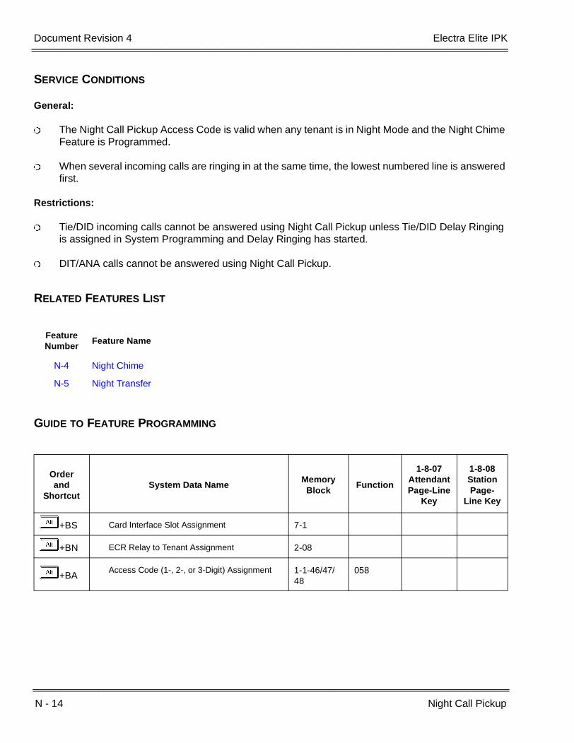
N - 14 Night Call Pickup
___________________________________________________________________________________
___________________________________________________________________________________Document Revision 4 Electra Elite IPK
SERVICE CONDITIONS
General:
The Night Call Pickup Access Code is valid when any tenant is in Night Mode and the Night Chime Feature is Programmed.
When several incoming calls are ringing in at the same time, the lowest numbered line is answered first.
Restrictions:
Tie/DID incoming calls cannot be answered using Night Call Pickup unless Tie/DID Delay Ringing is assigned in System Programming and Delay Ringing has started.
DIT/ANA calls cannot be answered using Night Call Pickup.
RELATED FEATURES LIST
GUIDE TO FEATURE PROGRAMMING
Feature Number
Feature Name
N-4 Night Chime
N-5 Night Transfer
Orderand
ShortcutSystem Data Name
Memory Block
Function
1-8-07AttendantPage-Line
Key
1-8-08StationPage-
Line Key
+BS Card Interface Slot Assignment 7-1
+BN ECR Relay to Tenant Assignment 2-08
+BAAccess Code (1-, 2-, or 3-Digit) Assignment 1-1-46/47/
48058
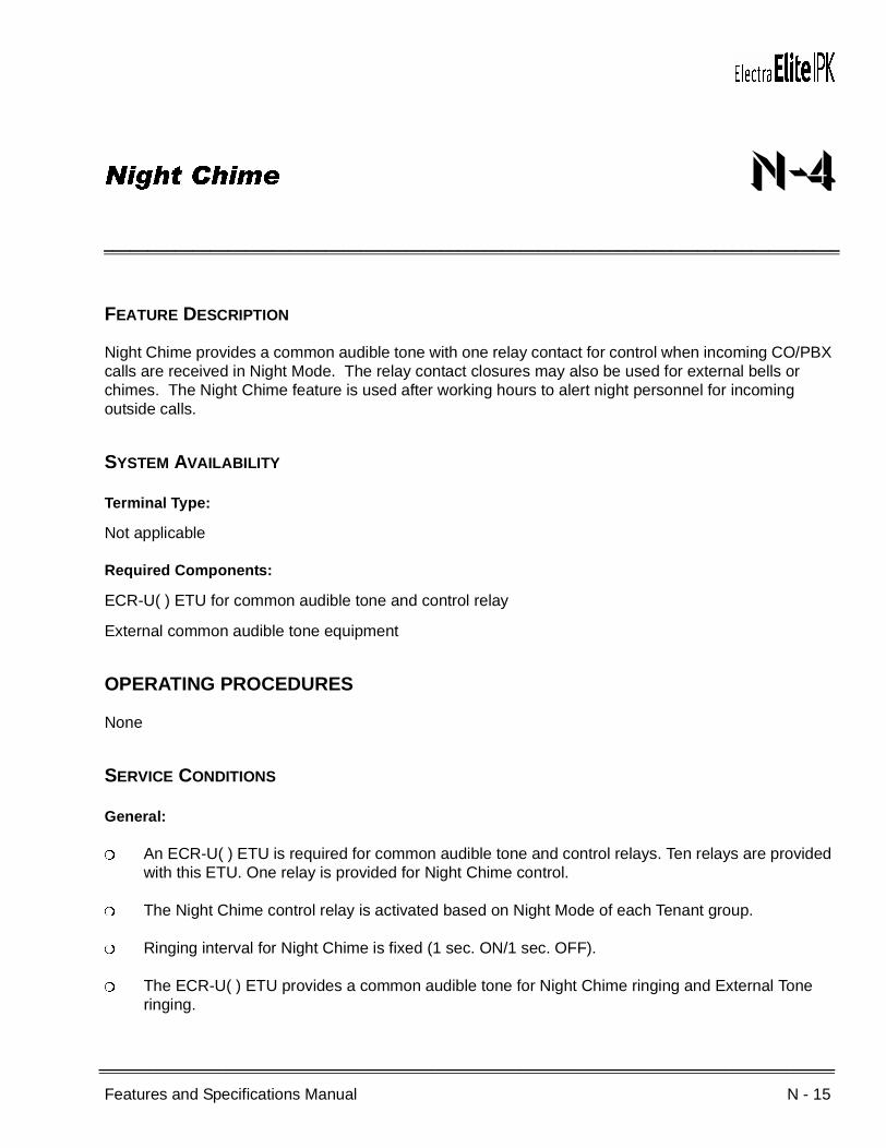
Features and Specifications Manual N - 15
___________________________________________________________________________________
___________________________________________________________________________________
Night Chime N-4
FEATURE DESCRIPTION
Night Chime provides a common audible tone with one relay contact for control when incoming CO/PBX calls are received in Night Mode. The relay contact closures may also be used for external bells or chimes. The Night Chime feature is used after working hours to alert night personnel for incoming outside calls.
SYSTEM AVAILABILITY
Terminal Type:
Not applicable
Required Components:
ECR-U( ) ETU for common audible tone and control relay
External common audible tone equipment
OPERATING PROCEDURES
None
SERVICE CONDITIONS
General:
An ECR-U( ) ETU is required for common audible tone and control relays. Ten relays are provided with this ETU. One relay is provided for Night Chime control.
The Night Chime control relay is activated based on Night Mode of each Tenant group.
Ringing interval for Night Chime is fixed (1 sec. ON/1 sec. OFF).
The ECR-U( ) ETU provides a common audible tone for Night Chime ringing and External Tone ringing.

N - 16 Night Chime
___________________________________________________________________________________
___________________________________________________________________________________Document Revision 4 Electra Elite IPK
The Night Chime equipment must be provided locally.
From a station in the same Tenant group, the Call Pickup Tenant Access Code can be used.
When a trunk is not assigned to a Tenant group, the Night Chime feature does not work.
Restrictions:
Tie/DID lines, DIT/ANA calls, and Automated Attendant do not activate the Night Chime relay.
RELATED FEATURES LIST
GUIDE TO FEATURE PROGRAMMING
Feature Number
Feature Name
N-3 Night Call Pickup
N-5 Night Transfer
Orderand
ShortcutSystem Data Name
Memory Block
Function
1-8-07AttendantPage-Line
Key
1-8-08StationPage-
Line Key
+BS Card Interface Slot Assignment 7-1
+BP External Ring Relay Cycle Selection 1-7-07
+BN ECR Relay to Tenant Assignment 2-08
When the system is at default this Memory Block must be programmed for the feature to be used.
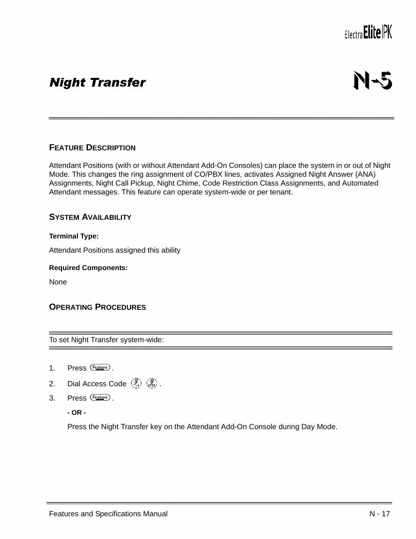
Features and Specifications Manual N - 17
___________________________________________________________________________________
___________________________________________________________________________________
Night Transfer N-5
FEATURE DESCRIPTION
Attendant Positions (with or without Attendant Add-On Consoles) can place the system in or out of Night Mode. This changes the ring assignment of CO/PBX lines, activates Assigned Night Answer (ANA) Assignments, Night Call Pickup, Night Chime, Code Restriction Class Assignments, and Automated Attendant messages. This feature can operate system-wide or per tenant.
SYSTEM AVAILABILITY
Terminal Type:
Attendant Positions assigned this ability
Required Components:
None
OPERATING PROCEDURES
To set Night Transfer system-wide:
1. Press A .
2. Dial Access Code HK.
3. Press A .
- OR -
Press the Night Transfer key on the Attendant Add-On Console during Day Mode.

N - 18 Night Transfer
___________________________________________________________________________________
___________________________________________________________________________________Document Revision 4 Electra Elite IPK
To cancel Night Transfer system-wide:
1. Press A .
2. Dial Access CodeHK.
3. Press A .
- OR -
Press the Night Transfer (NT) key on the Attendant Add-On Console during Night Mode.
To set per tenant:
1. Press A .
2. Dial Access Code HE.
3. Dial the Tenant number (KK~DG).
4. Press A .
To cancel per tenant:
1. Press A .
2. Dial Access CodeHE.
3. Dial the tenant number (KK~DG).
4. Press A .
To set weekend per tenant:
1. Press A .
2. Dial Access Code HK.
3. Dial the Tenant number (KK~DG).
4. Press A .

Electra Elite IPK Document Revision 4
Features and Specifications Manual N - 19
___________________________________________________________________________________
___________________________________________________________________________________
To cancel weekend per tenant:
1. Press A .
2. Dial Access CodeHK.
3. Dial the tenant number (KK~DG).
4. Press A .
SERVICE CONDITIONS
General:
The following features are affected when switching to the Night Mode:
Flexible Ringing Assignment
ANA Assignment
Code Restriction Class Assignment
Automated Attendant
Night Chime
Night Call Pickup
Feature Access keys or One-Touch keys can be assigned to set/cancel Night Transfer (system-wide or per tenant).
RELATED FEATURES LIST
Feature Number
Feature Name
C-19 Class of Service
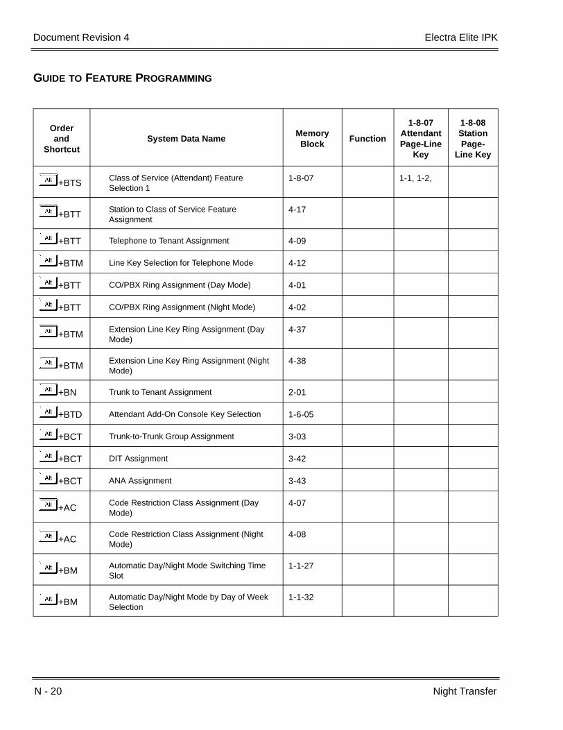
N - 20 Night Transfer
___________________________________________________________________________________
___________________________________________________________________________________Document Revision 4 Electra Elite IPK
GUIDE TO FEATURE PROGRAMMING
Orderand
ShortcutSystem Data Name
Memory Block
Function
1-8-07AttendantPage-Line
Key
1-8-08StationPage-
Line Key
+BTSClass of Service (Attendant) Feature Selection 1
1-8-07 1-1, 1-2,
+BTTStation to Class of Service Feature Assignment
4-17
+BTT Telephone to Tenant Assignment 4-09
+BTM Line Key Selection for Telephone Mode 4-12
+BTT CO/PBX Ring Assignment (Day Mode) 4-01
+BTT CO/PBX Ring Assignment (Night Mode) 4-02
+BTMExtension Line Key Ring Assignment (Day Mode)
4-37
+BTMExtension Line Key Ring Assignment (Night Mode)
4-38
+BN Trunk to Tenant Assignment 2-01
+BTD Attendant Add-On Console Key Selection 1-6-05
+BCT Trunk-to-Trunk Group Assignment 3-03
+BCT DIT Assignment 3-42
+BCT ANA Assignment 3-43
+ACCode Restriction Class Assignment (Day Mode)
4-07
+ACCode Restriction Class Assignment (Night Mode)
4-08
+BMAutomatic Day/Night Mode Switching Time Slot
1-1-27
+BMAutomatic Day/Night Mode by Day of Week Selection
1-1-32
Features and Specifications Manual O - 1
___________________________________________________________________________________
___________________________________________________________________________________
Off-Hook Ringing O-1
FEATURE DESCRIPTION
Off-Hook Ringing alerts a Multiline Terminal user that an incoming outside call is ringing to that station during another call. Off-Hook Ringing is provided through the built-in speaker of the Multiline Terminal at a lower volume than On-Hook Ringing.
SYSTEM AVAILABILITY
Terminal Type:
All Multiline Terminals
Required Components:
None
OPERATING PROCEDURES
To set off-hook ringing volume:
1. Go off-hook with the handset.
2. Dial the Access Code (default: FK).
3. Dial A from the dial pad.
4. Press press UV ( = decrease) or ( = increase) to decrease/increase off-hook ringing volume.
5. Go on-hook.
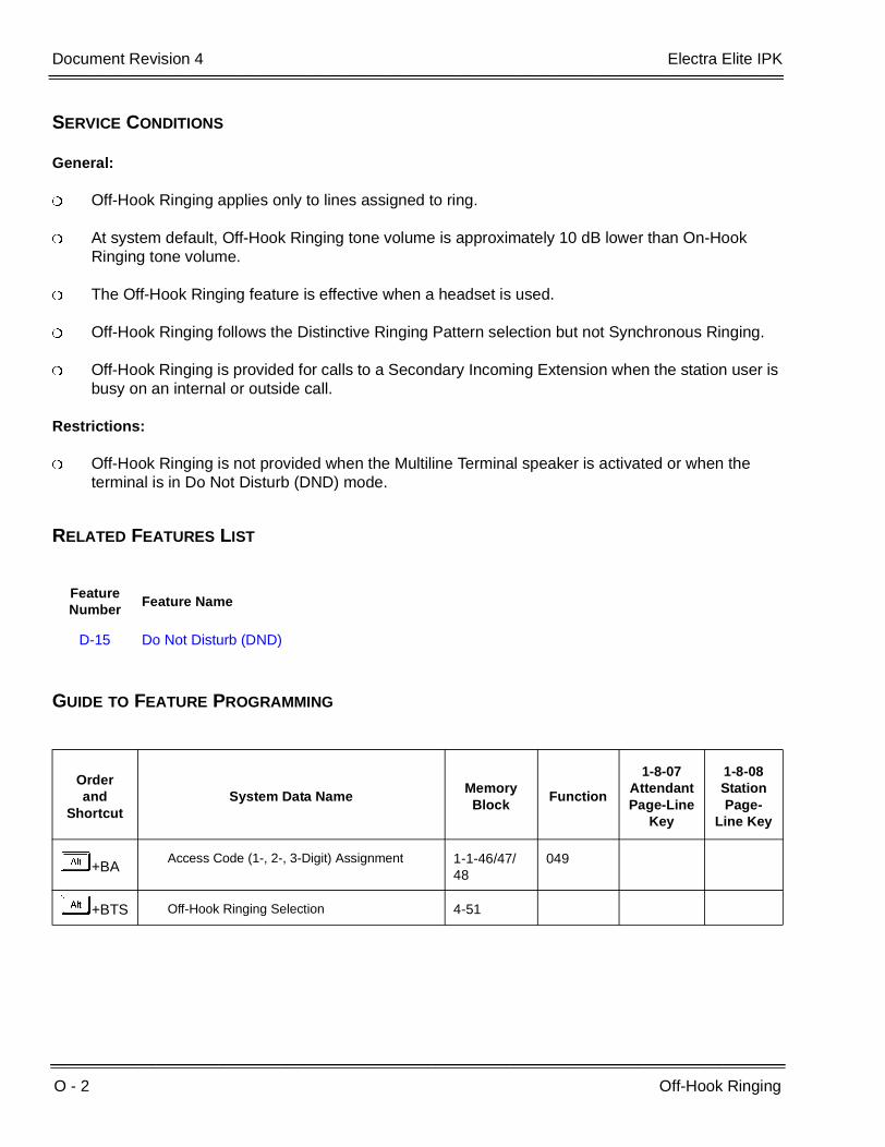
O - 2 Off-Hook Ringing
___________________________________________________________________________________
___________________________________________________________________________________Document Revision 4 Electra Elite IPK
SERVICE CONDITIONS
General:
Off-Hook Ringing applies only to lines assigned to ring.
At system default, Off-Hook Ringing tone volume is approximately 10 dB lower than On-Hook Ringing tone volume.
The Off-Hook Ringing feature is effective when a headset is used.
Off-Hook Ringing follows the Distinctive Ringing Pattern selection but not Synchronous Ringing.
Off-Hook Ringing is provided for calls to a Secondary Incoming Extension when the station user is busy on an internal or outside call.
Restrictions:
Off-Hook Ringing is not provided when the Multiline Terminal speaker is activated or when the terminal is in Do Not Disturb (DND) mode.
RELATED FEATURES LIST
GUIDE TO FEATURE PROGRAMMING
Feature Number
Feature Name
D-15 Do Not Disturb (DND)
Orderand
ShortcutSystem Data Name
Memory Block
Function
1-8-07AttendantPage-Line
Key
1-8-08StationPage-
Line Key
+BAAccess Code (1-, 2-, 3-Digit) Assignment 1-1-46/47/
48049
+BTS Off-Hook Ringing Selection 4-51

Features and Specifications Manual O - 3
___________________________________________________________________________________
___________________________________________________________________________________
Off-Premise Extension O-2
FEATURE DESCRIPTION
Off-Premise Extension allows a Single Line Telephone, located remotely from the main installation site, to access the system features with the same abilities as an on-premise Single Line Telephone.
SYSTEM AVAILABILITY
Terminal Type:
Single Line Telephones
Required components:
OPX(2)-U( ) ETU to support this feature
OPERATING PROCEDURES
Normal call handling procedures apply.
SERVICE CONDITIONS
General:
Each OPX(2)-U( ) ETU provides two circuits.
The maximum loop resistance between an OPX(2)-U( ) ETU and an Off-Premise Extension Single Line Telephone is 1600 ohms (including Single Line Telephone set resistance).
The OPX(2)-U( ) ETU has a built-in ringer (RSG). This ETU supports Synchronous Ringing and detects Dial Pulse/DTMF tones.
Restrictions:
The OPX(2)-U( ) ETU does not support an interface to a Voice Mail unit.

O - 4 Off-Premise Extension
___________________________________________________________________________________
___________________________________________________________________________________Document Revision 4 Electra Elite IPK
GUIDE TO FEATURE PROGRAMMING
Orderand
ShortcutSystem Data Name
Memory Block
Function
1-8-07AttendantPage-Line
Key
1-8-08StationPage-
Line Key
+BS Card Interface Slot Assignment 7-1

Features and Specifications Manual O - 5
___________________________________________________________________________________
___________________________________________________________________________________
One-Touch Feature Access O-3
FEATURE DESCRIPTION
One-Touch Feature Access is provided with Multiline Terminals to allow a Multiline Terminal user to press a single, flexible Feature Access key or One-Touch key to access many system features or System/Station Speed Dial without going off-hook first.
SYSTEM AVAILABILITY
Terminal Type:
All Multiline Terminals
Required Components:
None
OPERATING PROCEDURES
Refer to Related Features for the Operating Procedures.
SERVICE CONDITIONS
General:
You can press a single key to call a station, access a Speed Dial buffer, or activate a feature.
When the MIC key is programmed on a One-Touch Feature Access Key, set/cancel is operated by toggle.
Trunk access can be programmed on a Feature Access or One-Touch key.
When programming Feature Access or One-Touch keys, the Conference (CNF) key can be used to backspace and erase an entry.
Each One-Touch key can store up to 16 digits.
Nesting Dial is allowed under One-Touch keys.
O - 6 One-Touch Feature Access
___________________________________________________________________________________
___________________________________________________________________________________Document Revision 4 Electra Elite IPK
When programming Feature Access or One-Touch keys, press the Answer key, then press: Recall, Feature, Conf, Redial, Speaker, Answer, Transfer, or Hold to enter and store the applicable feature keys.
Restrictions:
Feature Access keys and One-Touch keys are similar in purpose and ability. Up to 16 feature access keys are available depending on system programming and available Line keys. One-Touch key availability is controlled by the type of Multiline Terminal.
RELATED FEATURES LIST
Feature Number
Feature Name
F-2 Feature Access – User Programmable
N-2 Nesting Dial
S-12 Speed Dial Stored Characters
S-11 Speed Dial – Station
Features and Specifications Manual P - 1
___________________________________________________________________________________
___________________________________________________________________________________
PC Programming P-1
FEATURE DESCRIPTION
The MIFM-U( ) ETU and System Administration Terminal (SAT) software allow the system to be programmed from a personal computer (PC). System Data is transferred to/from a diskette for backup of system data. SAT PC programming software also allows the user to print station designation strips to shorten installation time. End users can use end-user SAT PC programming software to program several features for their Multiline Terminals such as: Line Key Assignment, Telephone Names, Zone Paging Groups, or various programmed times.
ENHANCEMENT(S)
Release 2000:
With R2000 or higher, System Administration Terminal (SAT) software allows user programmable settings (e.g., DND, Call Forward) to be assigned and saved as part of the site database.
The following can be assigned and saved:
Call Forward/DND(Station)
DND Set
Call Forward – All Call Set
Call Forward – No Answer Set
Call Forward – Busy Set
Call Forward – Busy/No Answer Set
Call Forward – No Answer Split Set
Call Forward – Busy Split Set
Call Forward – Busy/No Answer Split Set
Call Forward – All Split Set

P - 2 PC Programming
___________________________________________________________________________________
___________________________________________________________________________________Document Revision 4 Electra Elite IPK
Miscellaneous (System Wide)
Day/Night Mode (System and Tenant)
Miscellaneous (Station Base)
Station Lockout Password
Save Dial
Station Lockout
Attendant Station Outgoing Lockout
Answer Preset
Background Music
MIC Settings
Callback Messages (Read Only)
Timed Alarm SLT
Customized Message Display
Miscellaneous (Trunk Base)
Automated Attendant/DISA Mode
Automatic Trunk-to-Trunk Transfer Mode
Automatic Trunk-to-Trunk Transfer Outgoing Trunk
Release 3000:
With R3000 or higher, PC Programming (SAT) can be used with the New MIFM-U20 ETU and the SPE(M)-U( ) ETU. When using a remote connection through the modem, the MOD-U10 Unit must be installed on the MIFM-U20. When programming using Ethernet, the ETH-U10 Unit and the POW-U10 Unit must be installed on the MIFM-U20 ETU. Modem and Ethernet ports are included with the SPE(M)-U( ) ETU.
SYSTEM AVAILABILITY
Terminal Type:
Not applicable

Electra Elite IPK Document Revision 4
Features and Specifications Manual P - 3
___________________________________________________________________________________
___________________________________________________________________________________
Required Components:
Pentium PC with Windows 95 or higher to run SAT PC programming
MIFM-U10 ETU with KMM( )U PAL chip installed and Modem Kit Unit
- OR -
MIFM-U20 ETU with MOD-U10 Unit, ETH-U10 Unit, and POW-U10 Unit installed
- OR -
SPE(M)-U( ) ETU
A comparison between the MIFM-U10 ETU, the MIFM-U20 ETU and the SPE(M)-U( ) ETU is provided by the following table.
OPERATING PROCEDURES
Refer to the Electra Elite IPK Programming Manual and the Electra Elite IPK and Electra Elite System Administration Terminals Technician’s Guide for programming instructions.
SERVICE CONDITIONS
General:
The MIFM-U( ) ETU provides the RS-232C connector for connection of a PC or a modem.
PC Requirements:
Pentium Processor
Microsoft Windows 95, 98, ME, XP, 2000 or NT 4.0 (or higher) operating system
At least 15 MB of free hard disk space
Feature MIFM-U10 ETU MIFM-U20 ETU SPE(M)-U( ) ETU
Hardware ComponentsMIFM-U10 ETUKMM( )U PAL chipModem Kit Unit
MIFM-U20 with KMM-U20 upgrade chip and the MOD-U10, POW-U10, and ETH-U10 Units.
SPE(M)-U( ) ETU with Soft Modem Activation Key
SAT Serial Programming Yes Yes Yes
SAT Modem Programming Yes (Optional) Yes (Optional) Yes (Standard)
Maximum Modem Speed 38.4K 38.4K 38.4K
SAT Ethernet (Intra/Internet) Programming
Yes (Optional) with Elite LAN PC Programming
Device)
Yes (Optional) for MIFM-U20 using ETH-U10 and
POW-U10 Units)Yes

P - 4 PC Programming
___________________________________________________________________________________
___________________________________________________________________________________Document Revision 4 Electra Elite IPK
Unused PC serial communication port (COM Port)
MNP Class 5 compatible modem when remote programming is required
Network Interface Card (NIC) when programming via LAN/WAN is required
When the Elite LAN PC programming device is used, the system can be programmed via the LAN or WAN. Version V4.00 LCR PC software is required.
The SPE(M)-U( ) ETU is programmed as an MIFM-U( ) ETU.
RELATED FEATURES LIST
Refer to the Electra Elite IPK and Electra Elite System Administration Terminals (SAT) Technician’s Guide for more details.
GUIDE TO FEATURE PROGRAMMING
Feature Number
Feature Name
R-4 Remote Programming
Orderand
ShortcutSystem Data Name
Memory Block
Function
1-8-07AttendantPage-Line
Key
1-8-08StationPage-
Line Key
+BS Card Interface Slot Assignment 7-1
+BS MIF (SMDR) Assignment 7-3-02
+BS MIF (LCR) Assignment 7-3-01
+CSS COM Port Parity/Stop Bit Setting Assignment 1-8-36
+CSS COM Port Baud Rate Setting Assignment 1-8-35
+CSSModem Port for Remote Programming Assignment
1-8-38
+CSN Site Name Assignment 1-8-18
+CSP PC Programming Password Assignment 1-8-17

Features and Specifications Manual P - 5
___________________________________________________________________________________
___________________________________________________________________________________
Pooled Line (Outgoing) P-2
FEATURE DESCRIPTION
Pooled Line (Outgoing) allows Multiline Terminal users to seize an outside line on one Pooled line key. One Pooled line key can accommodate a Trunk group or Route Advance Block.
SYSTEM AVAILABILITY
Terminal Type:
All Multiline Terminals
Required Components:
None
OPERATING PROCEDURES
To originate an outside call:
1. Press the Pooled line key, and wait for outside line dial tone.
2. Dial the desired telephone number.
SERVICE CONDITIONS
General:
A maximum of 48 pooled groups are allowed per system. Each pooled group corresponds to a Trunk Group number (1~32) or a Route Advance Block number (1~32).
Pooled Line LED indicates the status of the pooled group as follows:
On: All trunks in the pooled group are in use.
Off: Some or all trunks in the pooled group are idle.

P - 6 Pooled Line (Outgoing)
___________________________________________________________________________________
___________________________________________________________________________________Document Revision 4 Electra Elite IPK
When an idle Pooled line key is pressed, an idle trunk belonging to that pooled group is automatically selected. When the Electra Elite IPK is designated as KF registration, this feature is not available.
A user on a Pooled Line can access Call Park - System, Call Transfer, and Conference.
Trunk Queuing can be set when the Pooled line key is busy (red LED).
When a trunk is selected from Pooled line key, it appears on a CO line key or on a Call Appearance (CAP) key on the Multiline Terminal.
Restrictions:
A Pooled Line (Outgoing) cannot receive incoming calls.
GUIDE TO FEATURE PROGRAMMING
Orderand
ShortcutSystem Data Name
Memory Block
Function
1-8-07AttendantPage-Line
Key
1-8-08StationPage-
Line Key
+BCT Trunk-to-Trunk Group Assignment 3-03
+BTM Line Key Selection for Telephone Mode 4-12
+BN Line Key Selection 2-05
+BN Line Key Selection for Tenant Mode 2-06
When the system is at default this Memory Block must be programmed for the feature to be used.
Features and Specifications Manual P - 7
___________________________________________________________________________________
___________________________________________________________________________________
Power Failure Transfer P-3
FEATURE DESCRIPTION
Power Failure Transfer ensures that a customer has access to the Central Office network during a power outage. The CO/PBX tip and ring are automatically transferred to the tip and ring of a preselected Single Line Telephone. The Single Line Telephone can function in the system during normal operation or be used during a power failure. Each B64-U( ) KSU provides three circuits for this feature. When power returns, any ongoing conversation is disconnected.
SYSTEM AVAILABILITY
Terminal Type:
Single Line Telephones
Required Components:
SLI(4)/(8)-U( ) ETU
OPERATING PROCEDURES
A CO/PBX line is automatically switched to a locally provided Single Line Telephone when total system power is lost, and system battery backup expires.
SERVICE CONDITIONS
General:
The Single Line Telephones that are installed must provide dialing signals accepted by the outside exchange (Dial Pulse or Dual-Tone Multifrequency).
Only Single Line Telephones crossconnected at the MDF can be used for this feature.
Single Line Telephones and outside lines connected during power failure are fixed one-to-one.
Single Line Telephones must be equipped with a ground button for use with Ground-Start Trunks.

P - 8 Power Failure Transfer
___________________________________________________________________________________
___________________________________________________________________________________Document Revision 4 Electra Elite IPK
System features cannot be activated from Single Line Telephones when Power Failure Transfer is in operation.
When power is restored to the system, Power Failure Transfer is canceled. Calls in progress on Power Failure Transfer lines are disconnected.
GUIDE TO FEATURE PROGRAMMING
Orderand
ShortcutSystem Data Name
Memory Block
Function
1-8-07AttendantPage-Line
Key
1-8-08StationPage-
Line Key
+BS Card Interface Slot Assignment 7-1
Features and Specifications Manual P - 9
___________________________________________________________________________________
___________________________________________________________________________________
Preset Dialing P-4
FEATURE DESCRIPTION
Preset Dialing enables a Multiline Terminal user to originate an outgoing call by predialing digits on the keypad. After dialing the number, the user can go off-hook, press the Speaker key, or press a line key to make the call.
SYSTEM AVAILABILITY
Terminal Type:
All Multiline Terminals
Required Components:
None
OPERATING PROCEDURES
Using a Multiline Terminal:
1. Dial the telephone number using the keypad.
2. Go off-hook, or press E , or press a COW.
SERVICE CONDITIONS
General:
Confirmation tone is not heard while dialing.
When a digit is not dialed within 10 seconds, this feature is automatically canceled.
Pauses cannot be entered while dialing.

P - 10 Preset Dialing
___________________________________________________________________________________
___________________________________________________________________________________Document Revision 4 Electra Elite IPK
A maximum of 24 digits can be displayed.
A call originating using this feature is canceled when the Redial key, Hold key, Transfer key, or Recall key is pressed.
The LCR feature is in effect when using Preset Dialing unless directly accessing a CO line.
GUIDE TO FEATURE PROGRAMMING
Orderand
ShortcutSystem Data Name
Memory Block
Function
1-8-07AttendantPage-Line
Key
1-8-08StationPage-
Line Key
+BTS Class of Service (Station) Feature Selection 2 1-8-08 5-5
+AI Caller ID Preset Dial Outgoing CO Selection 4-44
When the system is at default this Memory Block must be programmed for the feature to be used.
Features and Specifications Manual P - 11
___________________________________________________________________________________
___________________________________________________________________________________
Prime Line Assignment P-5
Feature DESCRIPTION
Prime Line Assignment allows a station user to go off-hook and originate an outside call from the trunk assigned as the Prime Line without pressing the line key. This feature allows assignment of a trunk, Trunk group, or Route Advance Block.
SYSTEM AVAILABILITY
Terminal Type:
All Stations
Required Components:
None
OPERATING PROCEDURES
To originate a call:
1. Lift the handset or press E . Prime Line (outside line) is seized.
2. Dial the call.
To access an internal dial tone for Feature Access or an internal call at a Multiline Terminal:
1. Lift the handset or press E . Prime Line (outside line) is seized.
2. Press A .
3. Dial Access CodeFJ.
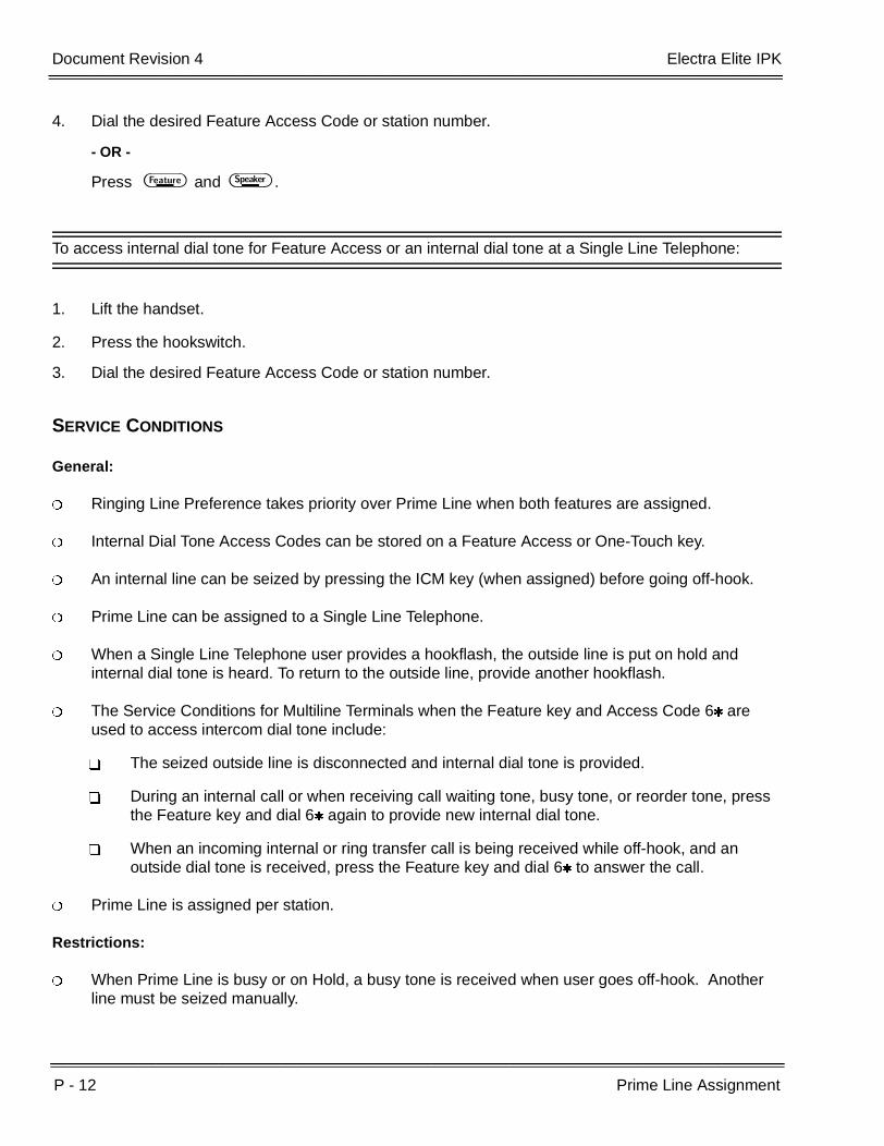
P - 12 Prime Line Assignment
___________________________________________________________________________________
___________________________________________________________________________________Document Revision 4 Electra Elite IPK
4. Dial the desired Feature Access Code or station number.
- OR -
Press A and E .
To access internal dial tone for Feature Access or an internal dial tone at a Single Line Telephone:
1. Lift the handset.
2. Press the hookswitch.
3. Dial the desired Feature Access Code or station number.
SERVICE CONDITIONS
General:
Ringing Line Preference takes priority over Prime Line when both features are assigned.
Internal Dial Tone Access Codes can be stored on a Feature Access or One-Touch key.
An internal line can be seized by pressing the ICM key (when assigned) before going off-hook.
Prime Line can be assigned to a Single Line Telephone.
When a Single Line Telephone user provides a hookflash, the outside line is put on hold and internal dial tone is heard. To return to the outside line, provide another hookflash.
The Service Conditions for Multiline Terminals when the Feature key and Access Code 6 are used to access intercom dial tone include:
The seized outside line is disconnected and internal dial tone is provided.
During an internal call or when receiving call waiting tone, busy tone, or reorder tone, press the Feature key and dial 6 again to provide new internal dial tone.
When an incoming internal or ring transfer call is being received while off-hook, and an outside dial tone is received, press the Feature key and dial 6 to answer the call.
Prime Line is assigned per station.
Restrictions:
When Prime Line is busy or on Hold, a busy tone is received when user goes off-hook. Another line must be seized manually.
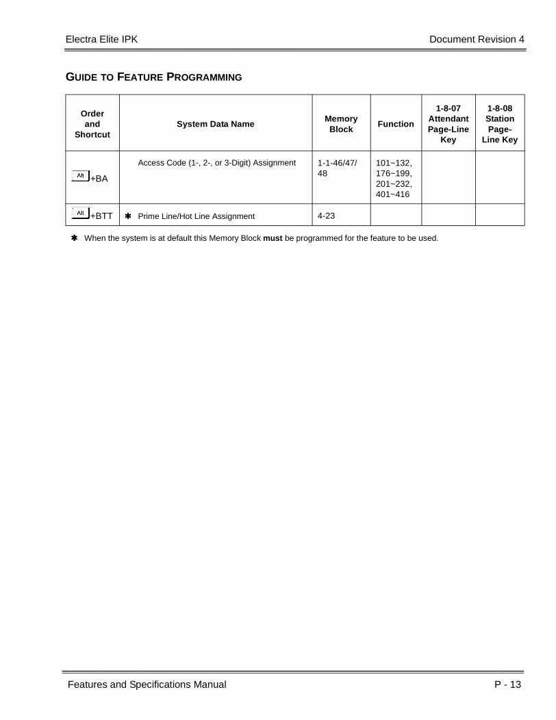
Electra Elite IPK Document Revision 4
Features and Specifications Manual P - 13
___________________________________________________________________________________
___________________________________________________________________________________
GUIDE TO FEATURE PROGRAMMING
Orderand
ShortcutSystem Data Name
Memory Block
Function
1-8-07AttendantPage-Line
Key
1-8-08StationPage-
Line Key
+BA
Access Code (1-, 2-, or 3-Digit) Assignment 1-1-46/47/48
101~132,176~199,201~232,401~416
+BTT Prime Line/Hot Line Assignment 4-23
When the system is at default this Memory Block must be programmed for the feature to be used.

P - 14 Prime Line Assignment
___________________________________________________________________________________
___________________________________________________________________________________Document Revision 4 Electra Elite IPK
THIS PAGE INTENTIONALLY LEFT BLANK
Features and Specifications Manual P - 15
___________________________________________________________________________________
___________________________________________________________________________________
Privacy on All Calls P-6
FEATURE DESCRIPTION
The system provides complete Privacy on All Calls. A station user cannot enter another conversation unless allowed using Barge-In, Add-On Conference, or Privacy Release.
SYSTEM AVAILABILITY
Terminal Type:
All Stations
Required Components:
None
OPERATING PROCEDURES
None
SERVICE CONDITIONS
General:
Only the person talking may allow a third or fourth party to enter the conversation using Add-On Conference or Privacy Release, unless the Barge-In feature is allowed at designated stations.
All stations have privacy at default.
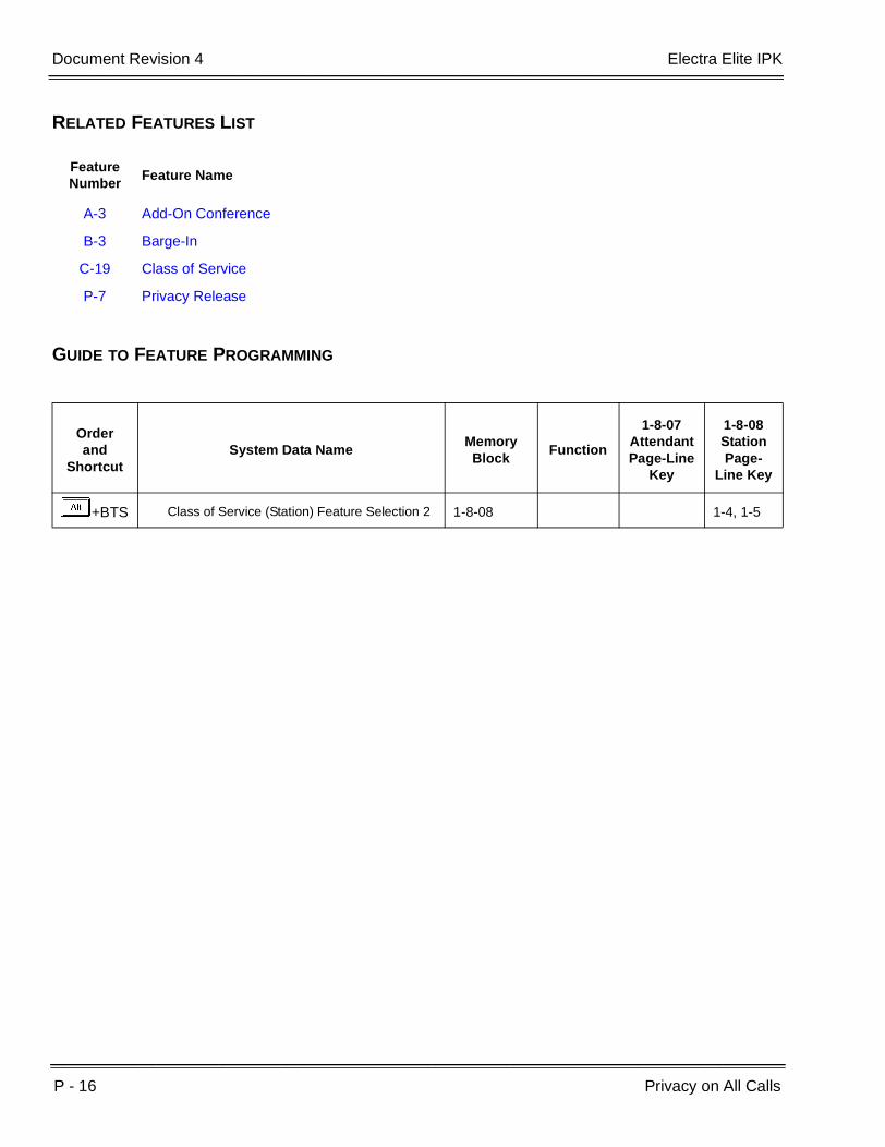
P - 16 Privacy on All Calls
___________________________________________________________________________________
___________________________________________________________________________________Document Revision 4 Electra Elite IPK
RELATED FEATURES LIST
GUIDE TO FEATURE PROGRAMMING
Feature Number
Feature Name
A-3 Add-On Conference
B-3 Barge-In
C-19 Class of Service
P-7 Privacy Release
Orderand
ShortcutSystem Data Name
Memory Block
Function
1-8-07AttendantPage-Line
Key
1-8-08StationPage-
Line Key
+BTS Class of Service (Station) Feature Selection 2 1-8-08 1-4, 1-5
Features and Specifications Manual P - 17
___________________________________________________________________________________
___________________________________________________________________________________
Privacy Release P-7
FEATURE DESCRIPTION
Privacy Release allows the multiline terminal user to release the privacy on an outside line by pressing a privacy release key programmed on the station. Another user can then press the same CO/PBX or CAP key to join the conversation in progress.
SYSTEM AVAILABILITY
Terminal Type:
All Multiline Terminals
Required Components:
None
OPERATING PROCEDURES
To program a Feature Access Key for Privacy Release from a Multiline Terminal:
1. Press A .
2. Press B .
3. Press the Feature Access Key.
4. Dial B.
5. Dial AK.
6. Press A .
P - 18 Privacy Release
___________________________________________________________________________________
___________________________________________________________________________________Document Revision 4 Electra Elite IPK
To program a One-Touch Key for Privacy Release from a Multiline Terminal:
1. Press A .
2. Press B .
3. Press the One-Touch Key.
4. Dial B.
5. Dial AK.
6. Press A .
To activate Privacy Release from a Multiline Terminal with a CO/PBX call in progress:
Press the Privacy Release key.
To enter a Conversation using the Privacy Release from a Multiline Terminal:
1. Lift the handset or press E .
2. Press the CO/PBX Line key or CAP key that released privacy.
SERVICE CONDITIONS
General:
Privacy Release can be activated or deactivated while a CO/PBX call is in progress.
The red Conf LED flashes during Privacy Release. After Privacy Release is canceled or all allowed parties have joined, the LED is off.
The Conf key LED indication for Privacy Release is the same as the indication for a conference call.
When Privacy Release is activated, the Conf key LED winks on all Multiline Terminals assigned to the same Tenant as the CO line with Privacy Release, even when the CO line is assigned to multiple Tenants.
When D is pressed from the same station that activated Privacy Release, the Privacy Release feature is canceled.
Electra Elite IPK Document Revision 4
Features and Specifications Manual P - 19
___________________________________________________________________________________
___________________________________________________________________________________
Holding an internal call has priority over Privacy Release.
When a CO assigned as a private line is Privacy Released, the Conf key at the shared private line flashes.
Restrictions:
Privacy Release is only available on an Outside line.
Only two stations can be added per CO/PBX call after Privacy Release. After two parties have joined the conversation, the Conf key LED at all stations that did not enter is turned off. A third station that tries to enter receives a busy signal.
When the originating caller abandons the call, the user cannot enter the call again.
Privacy Release cannot be activated again until both added stations release the CO/PBX line.
A maximum of 16 Privacy Release calls are available.
Voice Over is prohibited to a station that has activated Privacy Release.
When a station is receiving Voice Over, activating Privacy Release is ignored and Voice Over continues.
Privacy Release and Live Record are not allowed at the same time.
Privacy Release cannot be used on Single Line Telephones.
Specified CO/PBX seizure cannot be used to activate Privacy Release.
Privacy Release is not allowed when a conference is in progress.
To join a CO/PBX call using Privacy Release the originating CO/PBX key or CAP key must be assigned to that station.
RELATED FEATURES LIST
Feature Number
Feature Name
A-3 Add-On Conference
B-3 Barge-In
C-19 Class of Service

P - 20 Privacy Release
___________________________________________________________________________________
___________________________________________________________________________________Document Revision 4 Electra Elite IPK
GUIDE TO FEATURE PROGRAMMING
Orderand
ShortcutSystem Data Name
Memory Block
Function
1-8-07AttendantPage-Line
Key
1-8-08StationPage-
Line Key
+BN Trunk to Tenant Assignment 2-01
+BN Line Key Selection 2-05
+BTT Telephone to Tenant Assignment 4-09
+BN Line Key Selection for Tenant Mode 2-06
+BTM Line Key Selection for Telephone Mode 4-12
One-Touch and Feature Access keys are programmable through SAT but not using system programming.

Features and Specifications Manual P - 21
___________________________________________________________________________________
___________________________________________________________________________________
Private Lines P-8
FEATURE DESCRIPTION
Two outside lines can be programmed as private lines. Only a Multiline Terminal that is programmed for the Private Lines feature can access these private lines. The Private Line LED status is not displayed on any other Multiline Terminal.
SYSTEM AVAILABILITY
Terminal Type
All Stations
Required Components:
None
OPERATING PROCEDURES
None
SERVICE CONDITIONS
General:
The following combinations are possible:
Two stations with individual Private Lines
Two stations sharing one Private Line
One station with two Private Lines
Barge-In on a Private Line is possible only when the same Private Line is shared by two terminals.
Private Lines cannot be included in a conference and/or transferred except when two stations share a Private Line.

P - 22 Private Lines
___________________________________________________________________________________
___________________________________________________________________________________Document Revision 4 Electra Elite IPK
Private Lines cannot be accessed by a Trunk Access Code.
Tie lines can be assigned as Private Lines.
Private Lines cannot follow Call Forward assignments unless the destination telephones use the same Private Lines.
Use Memory Block 1-1-46 [Access Code (1-Digit) Assignment] or 1-1-47 [Access Code (2-Digit) Assignment] Function Number 050 or 051 to assign access code for CO/PBX/Centrex Line Seizure. Private Lines can be assigned to Single Line Telephones, and the user can access the line by dialing the specified access code.
Restrictions:
Last Number Redial does not access a Private Line.
RELATED FEATURES LIST
GUIDE TO FEATURE PROGRAMMING
Feature Number
Feature Name
A-3 Add-On Conference
B-3 Barge-In
Orderand
ShortcutSystem Data Name
Memory Block
Function
1-8-07AttendantPage-Line
Key
1-8-08StationPage-
Line Key
+BAAccess Code (1-, 2-, 3-Digit) Assignment 1-1-46/47/
48050,051
+BCS Private Line Assignment 1-1-29
When the system is at default this Memory Block must be programmed for the feature to be used.
Features and Specifications Manual P - 23
___________________________________________________________________________________
___________________________________________________________________________________
Programming from Multiline Terminal P-9
FEATURE DESCRIPTION
System Programming can be performed from designated Display Multiline Terminals in the first two ESI(8)-U( ) ETU ports. Some programming changes become effective immediately. Other programming changes become effective after applicable busy telephones and circuits become idle.
SYSTEM AVAILABILITY
Terminal Type:
Display Multiline Terminals
Required Components:
ESI(8)-U( ), ESIB(8)-U( ), and ESIE(8)-U( ) ETU
OPERATING PROCEDURES
Refer to the Electra Elite IPK Programming Manual for additional information.
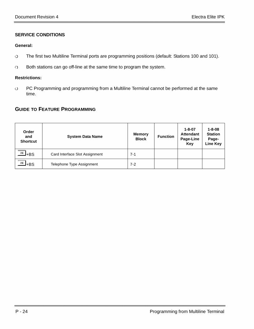
P - 24 Programming from Multiline Terminal
___________________________________________________________________________________
___________________________________________________________________________________Document Revision 4 Electra Elite IPK
SERVICE CONDITIONS
General:
The first two Multiline Terminal ports are programming positions (default: Stations 100 and 101).
Both stations can go off-line at the same time to program the system.
Restrictions:
PC Programming and programming from a Multiline Terminal cannot be performed at the same time.
GUIDE TO FEATURE PROGRAMMING
Orderand
ShortcutSystem Data Name
Memory Block
Function
1-8-07AttendantPage-Line
Key
1-8-08StationPage-
Line Key
+BS Card Interface Slot Assignment 7-1
+BS Telephone Type Assignment 7-2
Features and Specifications Manual P - 25
___________________________________________________________________________________
___________________________________________________________________________________
Pushbutton Dial – DTMF or DP P-10
FEATURE DESCRIPTION
Pushbutton Dial – DTMF or DP is provided on all Single Line Telephones and outside lines. Tie Lines are assigned per trunk to generate either Dual-Tone Multifrequency (DTMF) or Dial Pulse (DP) dialing signals.
SYSTEM AVAILABILITY
Terminal Type:
All Multiline Terminals with a push button dial pad
Required Components:
TLI(2)-U( ) or DTI-U( ) ETU assigned as Tie Lines
OPERATING PROCEDURES
None
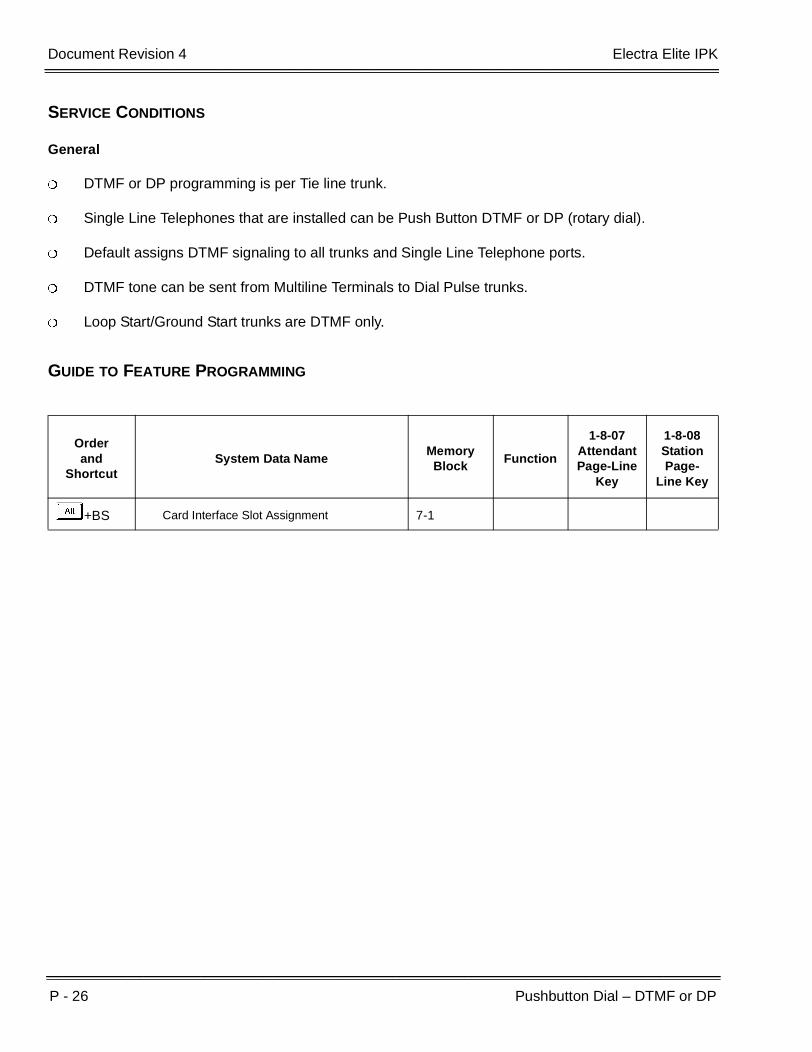
P - 26 Pushbutton Dial – DTMF or DP
___________________________________________________________________________________
___________________________________________________________________________________Document Revision 4 Electra Elite IPK
SERVICE CONDITIONS
General
DTMF or DP programming is per Tie line trunk.
Single Line Telephones that are installed can be Push Button DTMF or DP (rotary dial).
Default assigns DTMF signaling to all trunks and Single Line Telephone ports.
DTMF tone can be sent from Multiline Terminals to Dial Pulse trunks.
Loop Start/Ground Start trunks are DTMF only.
GUIDE TO FEATURE PROGRAMMING
Orderand
ShortcutSystem Data Name
Memory Block
Function
1-8-07AttendantPage-Line
Key
1-8-08StationPage-
Line Key
+BS Card Interface Slot Assignment 7-1
Features and Specifications Manual Q - 1
___________________________________________________________________________________
___________________________________________________________________________________
Quick Transfer to Voice Mail Q-1
FEATURE DESCRIPTION
A station user transferring a call can transfer the call to the called party voice mail box after the transferred call recalls, after an internal station number is dialed while performing a screened transfer, or during intercom calls.
SYSTEM AVAILABILITY
Terminal Type:
All Multiline Terminals allow either operation.
Single line telephones may perform the Quick Transfer only during screened transfer operations. They may not perform Quick Transfer after recall.
Required Components:
None
OPERATING PROCEDURES
To Quick Transfer a call while talking with an outside or internal party:
1. Press G , and wait for an internal dial tone.
2. Enter a station number, and wait for a ring back tone.
3. Dial the Quick Transfer Access Code (default: G). The outside party is transferred to the station user Voice Mail box.
4. Hang up.
5. The Voice Mail answers.
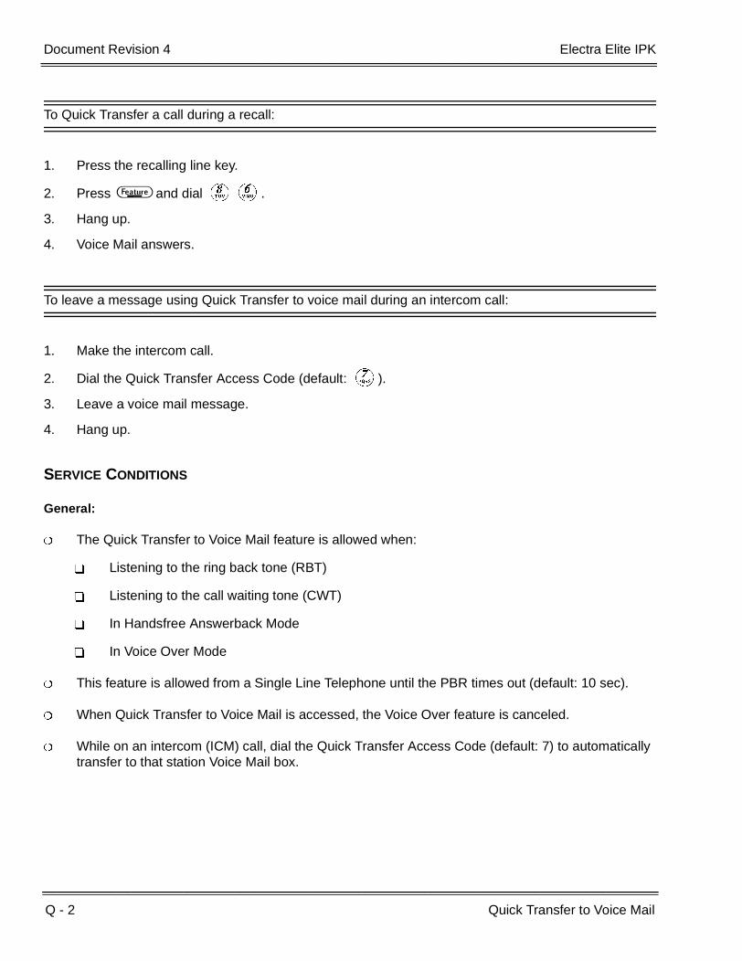
Q - 2 Quick Transfer to Voice Mail
___________________________________________________________________________________
___________________________________________________________________________________Document Revision 4 Electra Elite IPK
To Quick Transfer a call during a recall:
1. Press the recalling line key.
2. Press A and dial HF.
3. Hang up.
4. Voice Mail answers.
To leave a message using Quick Transfer to voice mail during an intercom call:
1. Make the intercom call.
2. Dial the Quick Transfer Access Code (default: G).
3. Leave a voice mail message.
4. Hang up.
SERVICE CONDITIONS
General:
The Quick Transfer to Voice Mail feature is allowed when:
Listening to the ring back tone (RBT)
Listening to the call waiting tone (CWT)
In Handsfree Answerback Mode
In Voice Over Mode
This feature is allowed from a Single Line Telephone until the PBR times out (default: 10 sec).
When Quick Transfer to Voice Mail is accessed, the Voice Over feature is canceled.
While on an intercom (ICM) call, dial the Quick Transfer Access Code (default: 7) to automatically transfer to that station Voice Mail box.
Electra Elite IPK Document Revision 4
Features and Specifications Manual Q - 3
___________________________________________________________________________________
___________________________________________________________________________________
Restrictions:
The Quick Transfer to Voice Mail is not allowed when caller is:
Listening to the busy tone (BT)
Talking on an internal line
Talking on an outside line
Making a conference call
Setting Automatic Callback
When 5-, 6-, or 7-digit station numbers are used, this feature is not available.
When a call is transferred to a station that is call forwarded to Voice Mail, or the Quick transfer to Voice Mail feature is used, the call must be released (blind transferred) before Voice Mail answers the call. During the transfer, the transferring party hears ring back tone, and the external party hears Music on Hold (MOH) or ringback tone until the transfer is completed. MOH or ring back tone is determined by Memory Block 4-66 (MOH or Ring Back Tone Selection). This condition applies to the following software versions:
GUIDE TO FEATURE PROGRAMMING
R1700 R2000 R2500 R3000 3500
R1.71 R2.01 R2.50 R3.00 R3.50
R2.02 R2.51 R3.01 R3.51
Orderand
ShortcutSystem Data Name
Memory Block
Function
1-8-07AttendantPage-Line
Key
1-8-08StationPage-
Line Key
+BA Intercom Feature Access Code Assignment 1-2-24 007
+AV Voice Mail Quick Transfer Master Hunt Number
1-8-26
When the system is at default this Memory Block must be programmed for the feature to be used.

Q - 4 Quick Transfer to Voice Mail
___________________________________________________________________________________
___________________________________________________________________________________Document Revision 4 Electra Elite IPK
THIS PAGE INTENTIONALLY LEFT BLANK

Features and Specifications Manual R - 1
___________________________________________________________________________________
___________________________________________________________________________________
Recall Key R-1
FEATURE DESCRIPTION
The Recall Key either generates a hookflash to access features provided by the outside exchange or abandons a call while retaining the CO/PBX line for another call. Each Multiline Terminal has a Recall key. The function of this key is programmed.
SYSTEM AVAILABILITY
Terminal Type:
All Multiline Terminals
Required Components:
None
OPERATING PROCEDURES
To use this feature with an outside CO call in progress:
1. Press C .
2. Receive new CO dial tone; line is not released.
To use this feature with a PBX/Centrex call in progress:
1. Press C .
2. Receive PBX/Centrex second dial tone.

R - 2 Recall Key
___________________________________________________________________________________
___________________________________________________________________________________Document Revision 4 Electra Elite IPK
SERVICE CONDITIONS
General:
The Recall key functions only on Loop Start or Ground Start Trunks.
A Drop key can be programmed on a Flexible Line key or One-Touch key to be used to abandon a call and retain the same PBX/Centrex line.
While receiving busy, error tone, or an internal call, press the Recall key to provide a new internal dial tone.
When you press the Recall key at an LCR station during a conversation with an outside party, and a CO Trunk is assigned using Memory Block 3-91 (Trunk Type Selection), the following occur:
The current call is dropped.
A new Least Cost Routing dial tone is heard.
Station Message Detail Recording starts again.
Code Restriction starts again.
When you press the Recall key during a conversation with an outside party, a PBX Trunk is assigned using Memory Block 3-91 (Trunk Type Selection), and Least Cost Routing Recall is assigned as Allow (LED On) using Memory Block 1-8-08 [Class of Service (Station) Feature Selection 2] Page 4 LK1, the following occur:
The current call is held by a PBX trunk.
A new PBX dial tone is heard.
Station Message Detail Recording starts again.
Code Restriction starts again.
When you press the Recall key during a conversation with an outside party, a PBX Trunk is assigned using Memory Block 3-91 (Trunk Type Selection), and Least Cost Routing Recall is assigned as Deny (LED Off) using Memory Block 1-8-08 [Class of Service (Station) Feature Selection 2] Page 4 LK1, the following occur:
The current call is dropped.
A new CO dial tone is heard.
Station Message Detail Recording starts again.
Code Restriction starts again.

Electra Elite IPK Document Revision 4
Features and Specifications Manual R - 3
___________________________________________________________________________________
___________________________________________________________________________________
When you press the Recall key during a conversation with an outside party, a Centrex Trunk Assume-9 is assigned using Memory Block 3-91 (Trunk Type Selection), and Least Cost Routing Recall is assigned as Allow (LED On) using Memory Block 1-8-08 [Class of Service (Station) Feature Selection 2] Page 4 LK1, the following occur:
The current call is held by a Centrex trunk.
A new Centrex dial tone is heard.
Station Message Detail Recording starts again.
Code Restriction starts again.
When you press the Recall key during a conversation with an outside party, a Centrex Trunk Assume-9 is assigned using Memory Block 3-91 (Trunk Type Selection), and Least Cost Routing Recall is assigned as Deny (LED Off) using Memory Block 1-8-08 [Class of Service (Station) Feature Selection 2] Page 4 LK1, the following occur:
The current call is dropped.
A new CO dial tone is heard.
Station Message Detail Recording starts again.
Code Restriction starts again.
A hookflash can be programmed as any digit in a Speed Dial buffer.
RELATED FEATURES LIST
Feature Number
Feature Name
C-19 Class of Service
D-19 Drop Key
R - 4 Recall Key
___________________________________________________________________________________
___________________________________________________________________________________Document Revision 4 Electra Elite IPK
GUIDE TO FEATURE PROGRAMMING
Orderand
ShortcutSystem Data Name
Memory Block
Function
1-8-07AttendantPage-Line
Key
1-8-08StationPage-
Line Key
+BCM Hookflash Time Selection 1-1-02
+BTI SLT Hookflash Signal Selection 1-3-02
+BAAccess Code (1, 2-, 3--Digit) Assignment 1-1-46/47/
48029
+BM Class of Service (Station) Feature Selection 2 1-8-08 4-1
+BTTStation to Class of Service Feature Assignment
4-17
When the system is at default this Memory Block must be programmed for the feature to be used.
Features and Specifications Manual R - 5
___________________________________________________________________________________
___________________________________________________________________________________
Recall With Station Identification R-2
FEATURE DESCRIPTION
A transferred, held, or camped-on call that is not answered in a specified time, recalls. During the recall, the Multiline Terminal display shows the station number that is recalling and the station that did not answer.
SYSTEM AVAILABILITY
Terminal Type:
Any Multiline Terminal with LCD
Required Components:
None
OPERATING PROCEDURES
Using a Multiline Terminal with LCD:
1. The Multiline Terminal user answers a CO/PBX incoming call.
2. Press G , and dial the desired station number.
3. Go on-hook.
4. After the timeout, when the call has not been answered, the recall tone is received and the CO/PBX line key LED intermittently winks. The station number where the call was transferred is indicated in the LCD.
5. Press the intermittently winking line key, and go off-hook to answer the recall.

R - 6 Recall With Station Identification
___________________________________________________________________________________
___________________________________________________________________________________Document Revision 4 Electra Elite IPK
SERVICE CONDITIONS
General:
I-Hold and Call Park indicates the station number that set these features.
RELATED FEATURES LIST
GUIDE TO FEATURE PROGRAMMING
Feature Number
Feature Name
C-14 Call Park – System
I-1 I-Hold Indication
Orderand
ShortcutSystem Data Name
Memory Block
Function
1-8-07AttendantPage-Line
Key
1-8-08StationPage-
Line Key
+BM Hold Recall Time Selection (Non Exclusive Hold)
1-1-03
+BM Station Transfer/Camp-On Recall Time Selection
1-1-12
+BM System Call Park Recall Time Selection 1-2-23
+BM Hold Recall Time Selection (Exclusive) 1-1-63
+AC Station to Timer Class of Service 4-71
+BTM Hold/Transfer Recall Display Selection 4-30
Features and Specifications Manual R - 7
___________________________________________________________________________________
___________________________________________________________________________________
Redial Key R-3
FEATURE DESCRIPTION
Users can press the Redial key and dial the Speed Dial buffer number to access System and Station Speed Dial. Users can also press the Redial key and to redial the last outside number dialed.
SYSTEM AVAILABILITY
Terminal type:
All Multiline Terminals
Required Components:
None
OPERATING PROCEDURES
Using a Multiline Terminal:
Last Number Redial
Key Function:
1. Press an idle CO/PBX/Tie line key.
2. Press B .
3. Dial J.
Multifunction (Dial Access:)
1. Press B .
2. Dial J.
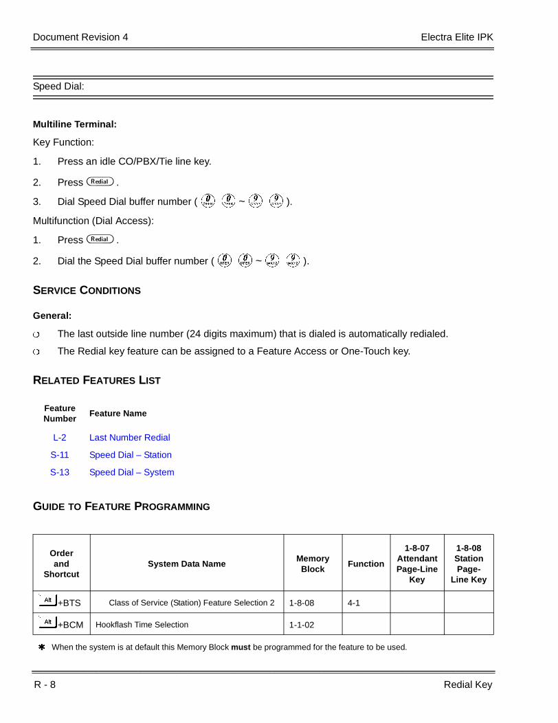
R - 8 Redial Key
___________________________________________________________________________________
___________________________________________________________________________________Document Revision 4 Electra Elite IPK
Speed Dial:
Multiline Terminal:
Key Function:
1. Press an idle CO/PBX/Tie line key.
2. Press B .
3. Dial Speed Dial buffer number (KK~II).
Multifunction (Dial Access):
1. Press B .
2. Dial the Speed Dial buffer number (KK~II).
SERVICE CONDITIONS
General:
The last outside line number (24 digits maximum) that is dialed is automatically redialed.
The Redial key feature can be assigned to a Feature Access or One-Touch key.
RELATED FEATURES LIST
GUIDE TO FEATURE PROGRAMMING
Feature Number
Feature Name
L-2 Last Number Redial
S-11 Speed Dial – Station
S-13 Speed Dial – System
Orderand
ShortcutSystem Data Name
Memory Block
Function
1-8-07AttendantPage-Line
Key
1-8-08StationPage-
Line Key
+BTS Class of Service (Station) Feature Selection 2 1-8-08 4-1
+BCM Hookflash Time Selection 1-1-02
When the system is at default this Memory Block must be programmed for the feature to be used.

Features and Specifications Manual R - 9
___________________________________________________________________________________
___________________________________________________________________________________
Remote Programming R-4
FEATURE DESCRIPTION
Remote Programming is used to modify and save all system parameters from a remote location using a modem. This is a variation of System Administration Terminal (SAT) PC Programming, and additional software other than PC Programming is not required.
SYSTEM AVAILABILITY
Terminal Type:
Not Applicable
Required Components:
PC with SAT PC Programming and modem installed at the remote location.
MIFM-U10/20 or SPE(M)-U( ) ETU
Modem Kit Unit mounted on the MIFM-U10 ETU or an external modem connected to the MIFM-U10 ETU through COM1. The MIFM-U20 requires installing an optional MOD-U10 Unit. The SPE(M)-U( ) ETU requires a modem to be installed.
OPERATING PROCEDURES
Refer to PC Programming Section of the Electra Elite IPK Programming Manual.
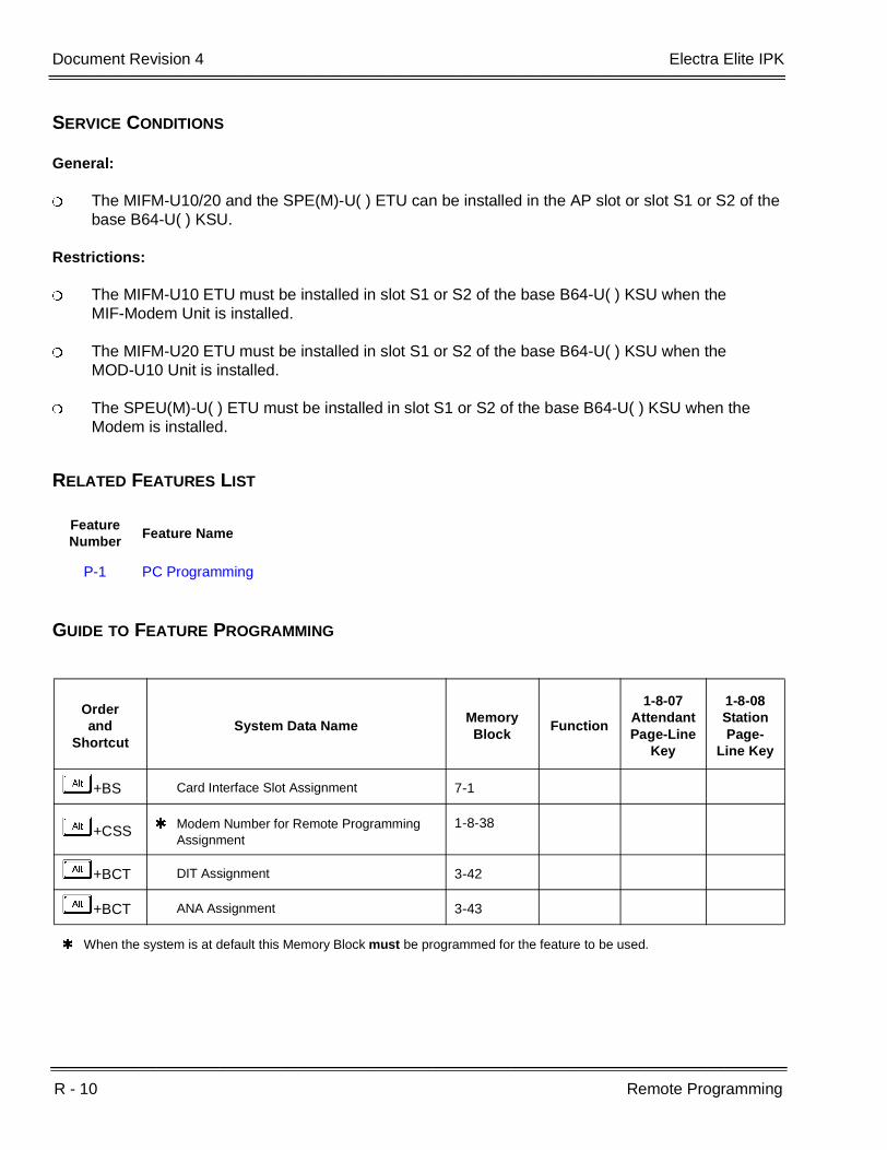
R - 10 Remote Programming
___________________________________________________________________________________
___________________________________________________________________________________Document Revision 4 Electra Elite IPK
SERVICE CONDITIONS
General:
The MIFM-U10/20 and the SPE(M)-U( ) ETU can be installed in the AP slot or slot S1 or S2 of the base B64-U( ) KSU.
Restrictions:
The MIFM-U10 ETU must be installed in slot S1 or S2 of the base B64-U( ) KSU when the MIF-Modem Unit is installed.
The MIFM-U20 ETU must be installed in slot S1 or S2 of the base B64-U( ) KSU when the MOD-U10 Unit is installed.
The SPEU(M)-U( ) ETU must be installed in slot S1 or S2 of the base B64-U( ) KSU when the Modem is installed.
RELATED FEATURES LIST
GUIDE TO FEATURE PROGRAMMING
Feature Number
Feature Name
P-1 PC Programming
Orderand
ShortcutSystem Data Name
Memory Block
Function
1-8-07AttendantPage-Line
Key
1-8-08StationPage-
Line Key
+BS Card Interface Slot Assignment 7-1
+CSS Modem Number for Remote Programming Assignment
1-8-38
+BCT DIT Assignment 3-42
+BCT ANA Assignment 3-43
When the system is at default this Memory Block must be programmed for the feature to be used.

Features and Specifications Manual R - 11
___________________________________________________________________________________
___________________________________________________________________________________
Resident System Program R-5
FEATURE DESCRIPTION
When power is supplied to the system, the hardware configuration is scanned and Resident System Program default values are assigned. This enables immediate operation, even before the system is programmed to accommodate the individual site requirements.
SYSTEM AVAILABILITY
Terminal Type:
Not applicable
Required Components:
None
OPERATING PROCEDURES
None
SERVICE CONDITIONS
General:
Default assignments for Multiline Terminals are as follows:
LK 01~ LK 08 corresponds to CO 01~ CO 08.
Default assignments for Attendant Add-On Consoles are as follows:
DSS1 Port 1
DSS 2 Port 2
DSS 3 Port 1
DSS 4 Port 2
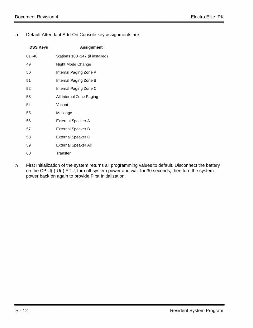
R - 12 Resident System Program
___________________________________________________________________________________
___________________________________________________________________________________Document Revision 4 Electra Elite IPK
Default Attendant Add-On Console key assignments are:
First Initialization of the system returns all programming values to default. Disconnect the battery on the CPUI( )-U( ) ETU, turn off system power and wait for 30 seconds, then turn the system power back on again to provide First Initialization.
DSS Keys Assignment
01~48 Stations 100~147 (if installed)
49 Night Mode Change
50 Internal Paging Zone A
51 Internal Paging Zone B
52 Internal Paging Zone C
53 All Internal Zone Paging
54 Vacant
55 Message
56 External Speaker A
57 External Speaker B
58 External Speaker C
59 External Speaker All
60 Transfer
Features and Specifications Manual R - 13
___________________________________________________________________________________
___________________________________________________________________________________
Restriction (Outgoing) R-6
FEATURE DESCRIPTION
Restriction (Outgoing) prohibits station users from originating outside calls per station/per trunk. At stations where Outgoing Restriction is assigned, a user can answer an incoming call, place and receive an internal call, or pick up a held line on a specified trunk. The number of digits dialed on outgoing calls may also be restricted per station.
SYSTEM AVAILABILITY
Terminal Type:
All Stations
Required Components:
None
OPERATING PROCEDURES
Operating procedures depend on System Programming.
SERVICE CONDITIONS
General:
The default program assigns no restrictions to any station.
When you press the Recall key or any key on the dial pad (while receiving dial tone), the CO/PBX line is dropped and reorder tone is sent to the station user.
Restricted outside lines cannot be seized by using a Trunk Access Code.

R - 14 Restriction (Outgoing)
___________________________________________________________________________________
___________________________________________________________________________________Document Revision 4 Electra Elite IPK
RELATED FEATURES LIST
GUIDE TO FEATURE PROGRAMMING
Feature Number
Feature Name
C-21 Code Restriction
Orderand
ShortcutSystem Data Name
Memory Block
Function
1-8-07AttendantPage-Line
Key
1-8-08StationPage-
Line Key
+BTT Trunk Outgoing Restriction 4-19
When the system is at default this Memory Block must be programmed for the feature to be used.

Features and Specifications Manual R - 15
___________________________________________________________________________________
___________________________________________________________________________________
Ring Tone Variation R-7
FEATURE DESCRIPTION
Ring Tone Variation provides three different tones that can be assigned per telephone or per CO/PBX. With this feature, the user can verify priority CO/PBX calls or identify particular ringing stations in an area.
SYSTEM AVAILABILITY
Terminal Type:
All Multiline Terminals
Required Components:
None
OPERATING PROCEDURES
None
SERVICE CONDITIONS
General:
This feature works closely with the Distinctive Ringing feature and pattern selections.
RELATED FEATURES LIST
Feature Number
Feature Name
D-14 Distinctive Ringing
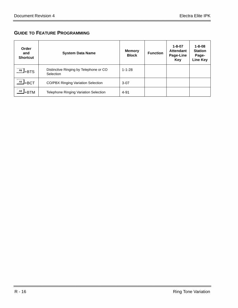
R - 16 Ring Tone Variation
___________________________________________________________________________________
___________________________________________________________________________________Document Revision 4 Electra Elite IPK
GUIDE TO FEATURE PROGRAMMING
Orderand
ShortcutSystem Data Name
Memory Block
Function
1-8-07AttendantPage-Line
Key
1-8-08StationPage-
Line Key
+BTSDistinctive Ringing by Telephone or CO Selection
1-1-28
+BCT CO/PBX Ringing Variation Selection 3-07
+BTM Telephone Ringing Variation Selection 4-91
Features and Specifications Manual R - 17
___________________________________________________________________________________
___________________________________________________________________________________
Ringing Line Preference R-8
FEATURE DESCRIPTION
Ringing Line Preference allows a station user to answer any outside ringing line by going off-hook without having to press the Answer key or the Flexible Line key associated with the ringing line.
SYSTEM AVAILABILITY
Terminal Type:
All Multiline Terminals
Required Components:
None
OPERATING PROCEDURES
Using a station where Ringing Line Preference is assigned:
1. Lift the handset.
2. Talk with the calling party.
To set/cancel using a Multiline Terminal:
1. Press A .
2. Press F ( F LED lights red).

R - 18 Ringing Line Preference
___________________________________________________________________________________
___________________________________________________________________________________Document Revision 4 Electra Elite IPK
SERVICE CONDITIONS
General:
Ringing Line Preference picks up lines that are programmed to ring at that station only.
For multiple calls in one of the following priority levels, the Multiline Terminal answers the line that was ringing first:
1. Voice Announcement or internal ringing call.
2. Ring transfer calls to a station.
3. Ringing call on an outside line key.
When the user sets Ringing Line Preference, the red Answer key LED is on at that station.
Ringing Line Preference has priority over Prime Line and Hot Line Assignment.
The CO line that begins ringing first is answered first.
All stations are assigned this feature at default.
GUIDE TO FEATURE PROGRAMMING
Orderand
ShortcutSystem Data Name
Memory Block
Function
1-8-07Attendant
Page-Line Key
1-8-08StationPage-
Line Key
+BTM Ringing Line Preference Selection 4-11
+BTM SIE/CAR Ringing Line Preference Selection 4-41
+BTS Class of Service (Station) Feature Selection 2 1-8-08 3-2
+BTT Station to Class of Service Feature Assignment
4-17
When the system is at default this Memory Block must be programmed for the feature to be used.

Features and Specifications Manual R - 19
___________________________________________________________________________________
___________________________________________________________________________________
Route Advance Block R-9
FEATURE DESCRIPTION
The Route Advance Block assigns up to 32 tables. Each table can contain four Trunk group priority levels from lowest cost to most expensive. Station users may have a Route Advance key programmed or may access this feature using a Trunk Access Code. When placing an outside call, the system follows the Route Advance table assigned for the station, ensuring that the lowest cost available Trunk group is used. Any Trunk group can be assigned to multiple route advance priority tables.
SYSTEM AVAILABILITY
Terminal Type:
All Stations
Required Components:
None
OPERATING PROCEDURES
Using a Multiline Terminal:
1. Press a line key assigned for a Route Advance Block.
2. Dial the desired number.
R - 20 Route Advance Block
___________________________________________________________________________________
___________________________________________________________________________________Document Revision 4 Electra Elite IPK
Using any station:
1. Lift the handset, and wait for internal dial tone.
2. Dial a Route Advance Block Access Code.
3. Dial the desired number.
SERVICE CONDITIONS
General:
Outgoing Restriction and Code Restriction rules apply to stations dialing out using Route Advance Blocks.
The line key assigned for a Route Advance Block is On when all trunks and Trunk groups assigned to the Route Advance Block are busy.
Stations are allowed to set Trunk Queuing to a Route Advance Block.
Up to four Trunk groups can be programmed in one Route Advance Block priority table.
Trunk groups can be repeated in multiple priority tables.
Restrictions:
The system must be assigned as MF registration.

Electra Elite IPK Document Revision 4
Features and Specifications Manual R - 21
___________________________________________________________________________________
___________________________________________________________________________________
GUIDE TO FEATURE PROGRAMMING
Orderand
ShortcutSystem Data Name
Memory Block
Function
1-8-07AttendantPage-Line
Key
1-8-08StationPage-
Line Key
+BCT Trunk-to-Trunk Group Assignment 3-03
+BCS Route Advance Block Assignment 1-1-30
+BAAccess Code (1-, 2-, or 3-Digit) Assignment 1-1-46/47/
48201 ~ 232
+BTM Line Key Selection for Telephone Mode 4-12
+BN Line Key Selection 2-05
+BN Line Key Selection for Tenant Mode 2-06
+ALN Trunk Group Outgoing Priority Selection 5-06
When the system is at default this Memory Block must be programmed for the feature to be used.

R - 22 Route Advance Block
___________________________________________________________________________________
___________________________________________________________________________________Document Revision 4 Electra Elite IPK
THIS PAGE INTENTIONALLY LEFT BLANK

Features and Specifications Manual S - 1
___________________________________________________________________________________
___________________________________________________________________________________
Save and Repeat S-1
FEATURE DESCRIPTION
Save and Repeat allows a Multiline Terminal user to save the last outside number dialed in system memory for later use.
SYSTEM AVAILABILITY
Terminal Type:
All Multiline Terminals
Required Components:
None
OPERATING PROCEDURES
To use this feature with an outgoing CO/PBX call in progress:
1. Press A .
2. Dial I.
3. The last number that was dialed is saved in memory.
4. Restore the handset or press E .
To repeat saved number:
1. Press B .
2. Dial L.
S - 2 Save and Repeat
___________________________________________________________________________________
___________________________________________________________________________________Document Revision 4 Electra Elite IPK
To repeat saved number (R4000 or higher):
1. Press B .
2. Dial L L.
SERVICE CONDITIONS
General:
Only one number (24 digits maximum) can be saved in the memory of each Multiline Terminal.
The saved number is retained by the memory backup battery.
A new number can be saved over the last Save and Repeat Number.
The Save and Repeat and the Store and Repeat features cannot be used simultaneously from a Multiline Terminal. The same memory area is shared by both features.
The user can program a Feature Access key or a One-Touch key as a Save key. A second Feature Access key or a One-Touch key can be assigned as a Repeat key. The LED does not light when a number is saved.
R4000 or higher requires # # to be used to repeat the saved number.
Restrictions:
Save and Repeat is valid on outside line calls only.
Related Features List
Feature Number
Feature Name
S-23 Store and Repeat

Features and Specifications Manual S - 3
___________________________________________________________________________________
___________________________________________________________________________________
Scrolling Directories S-2
FEATURE DESCRIPTION
Scrolling Directories functions like a telephone directory, and provides an Electra Elite IPK Display Multiline Terminal user a list of system and/or station speed dial numbers. Using Softkeys, the user can select a speed dial number and press the Speaker key or lift the handset to dial the number.
SYSTEM AVAILABILITY
Terminal Type:
All Display Multiline Terminals with Softkeys
Required Components:
None
OPERATING PROCEDURES
To use this feature:
1. Press theV(SYS or STA) Softkey to designate system or station speed dialing.
2. Press theV(UP or DOWN) Softkey to view the names/numbers listed in the directory.
- OR -
Press a dial pad key (to select the first letter of the name or number of the desired speed dial buffer) and dial J.
3. To dial the number press E or lift the handset.

S - 4 Scrolling Directories
___________________________________________________________________________________
___________________________________________________________________________________Document Revision 4 Electra Elite IPK
To use this feature with Account Code - Forced/Verified/Unverified:
1. Press theV(SYS. or STA. Softkey) to designate system or station speed dialing.
2. Press theV(UP or DOWN Softkey) to view the names/numbers listed in the directory.
- OR -
Press a dial pad key (to select the first letter of the name or number of the desired speed dial buffer) and dial J.
3. To dial the number press E or lift the handset.
4. Enter the Account Code.
SERVICE CONDITIONS
General:
Account Code – Forced/Verified/Unverified is compatible.
Names/numbers can be found in the directory in two ways:
Scroll the list using theV(UP or DOWN) Softkey.
Search by entering a letter or digit using the dial pad keys.
Both the name and number can be stored in the directory. When both are stored, only the name is shown in the LCD.
The third line of the LCD displays the Softkey designations:
SYS System Speed Dial Numbers.
STA Station Speed Dial Numbers.
UP Moves up to display additional System or Station Speed Dial numbers.
DOWN Moves down to display additional System or Station Speed Dial numbers.
When the Feature key or digit key is not pressed within 10 seconds, scrolling is canceled.
When scrolling, the system uses the following criteria to display the information in the order listed below:
Spaces (between alphabetical characters)
Alphabetical Characters
Digits
Special Characters

Electra Elite IPK Document Revision 4
Features and Specifications Manual S - 5
___________________________________________________________________________________
___________________________________________________________________________________
When more than one entry has the same name, the Speed Dial buffer with the lowest number is displayed first (i.e., buffer 04 is displayed before buffer 08).
Users can scroll Speed Dial buffers that are included in their Tenant Group only.
The spaces programmed in the beginning of a name are ignored during scrolling for sorting (i.e., ^^^Jean is regarded as Jean with ^ being equal to a space).
The speed dial buffers can be manually searched by scrolling through the Speed Dial Directory or the search can be narrowed down to the first letter of the name or first digit of the phone number. For the first letter of the name, the user can use the dial pad key with that letter on it. For example to search for NEC, the user dials 66 (i.e., 6 has three letters, M, N and O).Dial 66 to reach names starting with alphabet N and press to be used as an Enter key.
The LCD displays the name(s) starting with N. The user can then scroll down to the applicablename and make a selection.
Dial Pad 0~9 is valid for searching. The following shows the relation between Dial Pad and Alphabet/Digit:
Dial Pad 0 0
Dial Pad 1 1
Dial Pad 2 ABC2
Dial Pad 3 DEF3
Dial Pad 4 GHI4
Dial Pad 5 JKL5
Dial Pad 6 MNO6
Dial Pad 7 PQRS7
Dial Pad 8 TUV8
Dial Pad 9 WXYZ9
When the system is programmed as Key Function, select a number in the display, and press an idle trunk line key to dial it.
When the user is viewing the directory to select the number to be dialed, an incoming call to that station is treated in the same way as a call to a User Programming Mode station.
Scrolling mode is canceled when one of the following keys is pressed: Hold, Transfer, Answer, Redial, One-Touch, or Feature Access.
Key operation is ignored when Conf or Recall is pressed during scrolling.

S - 6 Scrolling Directories
___________________________________________________________________________________
___________________________________________________________________________________Document Revision 4 Electra Elite IPK
A maximum 12 characters are displayed in the Multiline Terminal LCD when the system is programmed for 1000 System Speed Dial numbers.
A maximum 13 characters are displayed in the Multiline Terminal LCD for Station Speed Dial or when programmed for 100 System Speed Dial numbers.
When the stored name/number exceeds 12 or 13 characters, only the first 12 or 13 characters are displayed in the Multiline Terminal LCD.
Restrictions:
Scrolling Directories can be used only while the station is idle.
When the System Speed Dial Display Assignment is used to restrict Tenants from viewing the numbers stored in System Speed Dial buffers, the scrolling follows these conditions:
When both Name and Number are stored, the user can scroll System Speed Dial buffers.
When only the Number is stored, the user cannot scroll System Speed Dial buffers.
When System or Station Speed Dial data is stored or changed by PC Programming, the changes are not displayed by the scrolling feature until the PC Programming connection is released.
GUIDE TO FEATURE PROGRAMMING
Orderand
ShortcutSystem Data Name
Memory Block
Function
1-8-07Attendant
Page-Line Key
1-8-08StationPage-
Line Key
+BE Speed Dial Number/Name Display Selection 1-1-33
+BE Speed Dial Buffer Allocation 1-1-35
+BN System Speed Dial Display Assignment 2-07
+AC System Speed Dial Restriction by Tenant 1-1-18

Features and Specifications Manual S - 7
___________________________________________________________________________________
___________________________________________________________________________________
Secondary Incoming Extension S-3
FEATURE DESCRIPTION
A Secondary Incoming Extension (SIE) can be assigned on a Flexible Line key. The status is indicated by the LED of the assigned SIE. An incoming internal, ringing Tie/DID, DIT/ANA, CO Transfer Ring, or call forwarded call can be picked up from an SIE.
SYSTEM AVAILABILITY
Terminal Type:
All Multiline Terminals
Required Components:
None
OPERATING PROCEDURES
To answer a secondary incoming extension call:
1. Receive an incoming ringing call on a Secondary Incoming Extension key.
2. Press the Secondary Incoming Extension key or go off-hook when Ringing Line Preference is assigned, and receive the call.
3. Talk with party. (Normal call handling procedures apply.)

S - 8 Secondary Incoming Extension
___________________________________________________________________________________
___________________________________________________________________________________Document Revision 4 Electra Elite IPK
SERVICE CONDITIONS
General:
Calls that recall to a station are not indicated by the LED and do not ring on a Secondary Incoming Extension.
Tone Override and Camp-On calls to a station are indicated by the LED and ring on a Secondary Incoming Extension.
Calls cannot be originated from a Secondary Incoming Extension.
Off-Hook Ringing is provided with calls ringing into Secondary Incoming Extensions.
Secondary Incoming Extensions cannot be set for Call Forward.
Internal and outside line calls answered from a Secondary Incoming Extension become the answering station user call.
Off-Hook indication busy lamp field (BLF) is not provided on the Secondary Incoming Extension.
When a Secondary Incoming Extension call is received and answered while the user is on an internal or outside line call, the first call is automatically put on hold.
Restrictions:
A station number cannot be programmed as a Secondary Incoming Extension on multiple Flexible Line keys on a Multiline Terminal.
Intercom voice signaling to another station cannot be picked up at the Secondary Incoming Extension. The LED on the Secondary Incoming Extension indicates Idle.
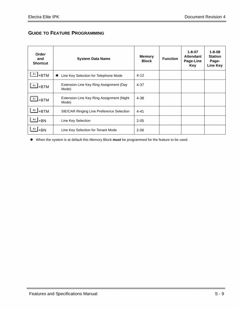
Electra Elite IPK Document Revision 4
Features and Specifications Manual S - 9
___________________________________________________________________________________
___________________________________________________________________________________
GUIDE TO FEATURE PROGRAMMING
Orderand
ShortcutSystem Data Name
Memory Block
Function
1-8-07AttendantPage-Line
Key
1-8-08StationPage-
Line Key
+BTM Line Key Selection for Telephone Mode 4-12
+BTMExtension Line Key Ring Assignment (Day Mode)
4-37
+BTMExtension Line Key Ring Assignment (Night Mode)
4-38
+BTM SIE/CAR Ringing Line Preference Selection 4-41
+BN Line Key Selection 2-05
+BN Line Key Selection for Tenant Mode 2-06
When the system is at default this Memory Block must be programmed for the feature to be used.

S - 10 Secondary Incoming Extension
___________________________________________________________________________________
___________________________________________________________________________________Document Revision 4 Electra Elite IPK
THIS PAGE INTENTIONALLY LEFT BLANK
Features and Specifications Manual S - 11
___________________________________________________________________________________
___________________________________________________________________________________
Seized Trunk Name/Number Display S-4
FEATURE DESCRIPTION
Seized Trunk Name/Number Display shows the programmed telephone name or number of each trunk in the system. The name or number is displayed on the Multiline Terminal LCD when a trunk is seized.
SYSTEM AVAILABILITY
Terminal Type:
All Multiline Terminals with an LCD
Required Components:
None
OPERATING PROCEDURES
For an outside call in progress (after Elapsed Call Time starts):
1. Press A .
2. Dial C.
3. The trunk number and assigned name or number are briefly displayed.
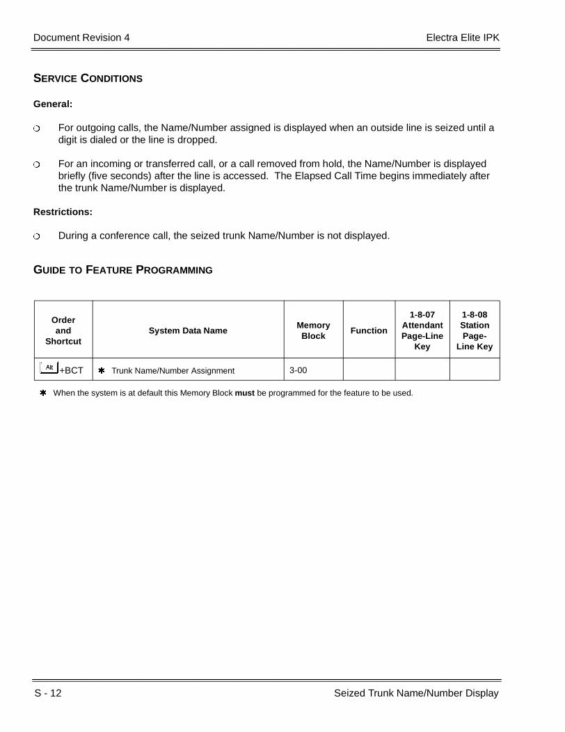
S - 12 Seized Trunk Name/Number Display
___________________________________________________________________________________
___________________________________________________________________________________Document Revision 4 Electra Elite IPK
SERVICE CONDITIONS
General:
For outgoing calls, the Name/Number assigned is displayed when an outside line is seized until a digit is dialed or the line is dropped.
For an incoming or transferred call, or a call removed from hold, the Name/Number is displayed briefly (five seconds) after the line is accessed. The Elapsed Call Time begins immediately after the trunk Name/Number is displayed.
Restrictions:
During a conference call, the seized trunk Name/Number is not displayed.
GUIDE TO FEATURE PROGRAMMING
Orderand
ShortcutSystem Data Name
Memory Block
Function
1-8-07AttendantPage-Line
Key
1-8-08StationPage-
Line Key
+BCT Trunk Name/Number Assignment 3-00
When the system is at default this Memory Block must be programmed for the feature to be used.
Features and Specifications Manual S - 13
___________________________________________________________________________________
___________________________________________________________________________________
Simplified Call Distribution S-5
FEATURE DESCRIPTION
Simplified Call Distribution distributes calls evenly to all members of a hunt group. It is very similar to UCD but does not require members to control call processing status by logging off. Hunting is instituted when a DIT, DID, TIE or VRS(4)-U( ) ETU call is terminated at an SCD group pilot number. Up to 32 SCD members can be divided among four SCD groups or assigned in one SCD group.
SYSTEM AVAILABILITY
Terminal Type:
Not applicable
Required Components:
None
OPERATING PROCEDURES
None
SERVICE CONDITIONS
General:
The SCD hunt is circular, and the starting point is the station that received the last SCD call.
SCD calls follow Station Call Forward – All Call settings.
When an SCD call is unanswered, the Electra Elite IPK system uses the Call Forward – No Answer time to send the call to the next available SCD station. This forward is a single event and does not repeat itself for the duration of that SCD call.

S - 14 Simplified Call Distribution
___________________________________________________________________________________
___________________________________________________________________________________Document Revision 4 Electra Elite IPK
Restrictions:
SCD is not available for Voice Mail, Automated Attendant transferred calls, or station transferred calls.
SCD is not available for intercom calls.
When 5-, 6-, or 7-digit station numbers are used, this feature is not available.
GUIDE TO FEATURE PROGRAMMING
Orderand
ShortcutSystem Data Name
Memory Block
Function
1-8-07Attendant
Page-Line Key
1-8-08StationPage-
Line Key
+AA SCD (Simplified Call Distribution) Pilot Number Assignment
1-8-29
+AA SCD Group Agent Assignment 1-8-30
+BCT DIT Assignment 3-42
+BCT ANA Assignment 3-43
When the system is at default this Memory Block must be programmed for the feature to be used.

Features and Specifications Manual S - 15
___________________________________________________________________________________
___________________________________________________________________________________
Single Point of Entry (SPE) S-6
FEATURE DESCRIPTION
This feature provides a single access point (remote or direct) to configure the system and/or individual ETUs. The SPE(M)-U( ) ETU provides the same function as the MIFM-U10 ETU with the KMM( )-U PAL chip installed or the MIFM-U20 ETU with the KMM-U20 upgrade chip installed, and comes with a standard built-in modem An Ethernet port is provided to allow programming over a network using TCP/IP.
The SPE(M)-U( ) ETU has six physical COM ports. Two ports go through the backplane to COM1 for PC Programming and COM2 for SMDR on the side of the KSU just like an MIFM-U( ) ETU. The other four COM ports (COM-A, COM-B, COM-C, COM-D) are accessible along the front of the ETU. These four ports are used to interface other programmable ETUs such as VMS.
A comparison between the MIFM-U10 ETU, the MIFM-U20 ETU and the SPE(M)-U( ) ETU is provided by the following table.
Feature MIFM-U10 ETU MIFM-U20 ETU SPE(M)-U( ) ETU
Hardware ComponentsMIFM-U10 ETUKMM( )U PAL chipModem Kit Unit
MIFM-U20 with KMM-U20 upgrade chip and the MOD-U10, POW-U10, and ETH-U10 Units.
SPE(M)-U( ) ETU with Soft Modem Activation Key
SAT Serial Programming Yes Yes Yes
SAT Modem Programming Yes (Optional) Yes (Optional) Yes (Standard)
Maximum Modem Speed 38.4K 38.4K 38.4K
SAT Ethernet (Intra/Internet) Programming
Yes (Optional) with Elite LAN PC Programming
Device)
Yes (Optional) for MIFM-U20 using ETH-U10 and
POW-U10 Units)Yes
LCR Serial Programming Yes Yes Yes
LCR Modem Programming Yes Yes Yes
LCR Ethernet Programming No Yes Yes
Serial SMDR Yes Yes Yes
Ethernet SMDR NoYes
(simultaneous on serial also)Yes
(simultaneous on serial also)

S - 16 Single Point of Entry (SPE)
___________________________________________________________________________________
___________________________________________________________________________________Document Revision 4 Electra Elite IPK
SYSTEM AVAILABILITY
Required Software:
No special KSU software
SAT PC Programming Software R1.70 or higher
LCR PC Programming Software Version 4.03 or higher
CoSession Update
Required Components:
SPE(M)-U( ) ETU
SERVICE CONDITIONS
General:
The SPE(M)-U( ) ETU provides the following communication methods to the key telephone system and individual installed ETUs:
Serial using COM1 on the KTS chassis
Modem
Ethernet
SMDR Record Storage when Printer is not connected
Approximately 100 call records
Maximum of 200 records in non-volatile Memory
Maximum of 200 records in non-volatile Memory
Caller ID Storage 50 per Station50 per Station in
non-volatile Memory50 per Station in
non-volatile Memory
VM CoSession using KSU serial port (no open box)
No No Yes
VM CoSession using modem not on VM ETU
No No Yes
VM CoSession using Ethernet
No No Yes
BRT/PRT/CCH Remote Debugging
No No Yes
Feature MIFM-U10 ETU MIFM-U20 ETU SPE(M)-U( ) ETU

Electra Elite IPK Document Revision 4
Features and Specifications Manual S - 17
___________________________________________________________________________________
___________________________________________________________________________________
Connectors on front of the SPE(M)-U( ) ETU are 10-pin RJ45 jacks, and a special SPE serial cable must be used with the SPE COM ports. COM-A and COM-B are fixed DTE interfaces. COM-C and COM -D each have a DIP switch that allows these ports to be set as either DTE or DCE interfaces. Factory defaults include DTE interface for COM-A and COM-B ports and DCE interface for COM-C and COM-D ports.
The SPE(M)-U( ) ETU has a 10/100 Mbps Ethernet port with an auto-crossover and auto-negotiating link that allows connectivity through a customer firewall to the remote office.
The SPE(M)-U( ) ETU is a hot-swap interface ETU that includes a Web-based interface for easy configuration of the SPE.
When the printer or I/O device is not ready (e.g., out of paper or the cable is disconnected) approximately 200 call records are saved in the SPE(M)-U( ) ETU buffer. When the buffer is full, the newest record replaces the oldest record.
A brief delay may be encountered when trying to go off hook on Dterm terminals immediately following boot up and/or hardware or software resets.
Restrictions:
The SPE(M)-U( ) ETU can be installed only in the AP, S1, or S2 slot of the first KSU. When the Modem is required, the ETU must be installed in slot S1 or S2.
An SPE(M)-U( ) ETU software application must be installed for the following connections:
Electra Elite IPK SAT (R1000 and lower)
Electra Elite LCR (Version 4.00 and lower)
Wireless Service Console (WSC)
CoSession Client (Voicemail Programming
BRT/PRT/CNF/CCH (Remote debugging)
PC Programming applications that can communicate to the SPE(M)-U( ) ETU without using the SPE PC application include:
Electra Elite IPK SAT (R1700 and higher)
Electra Elite LCR (Version 4.03 and higher)
COM54 is used by SAT and LCR PC-based applications and COM4 is used by the WSC PC-based applications, but only one of these applications can be used at a time.
SPE Serial Port D (COM53) must be used to connect to the Voicemail CMS/FMS/VMS/CTI/VP ETU.
Voicemail BRU and BRFT software utilities are not supported by the SPE(M)-U( ) ETU.

S - 18 Single Point of Entry (SPE)
___________________________________________________________________________________
___________________________________________________________________________________Document Revision 4 Electra Elite IPK
For Serial data communication to the SPE(M)-U( ) ETU from a PC, the physical COM1 port normally used for Serial communication is superimposed on the Transport medium physical COM port by a series of Virtual COM ports (COM4 and COM50~54). the Virtual COM ports are mapped to physical COM ports on the SPE(M)-U( ) ETU as follows:
COM4 → CoSession (COM53)
COM4 → WCS (COM54)
COM50 SPE Serial Port A
COM51 SPE Serial Port B
COM52 SPE Serial Port C
COM53 SPE Serial Port D
COM54 → SAT/LCR
When using modem or serial connections and simultaneous connections are made using virtual COM ports to other ETUs (e.g., CCH or PRI), and SAT download is required, the respective virtual COM ports must be temporarily disabled by unchecking the COM port in the Configuration Screen and clicking on the update key. After the SAT download is complete, the virtual COM ports can be enabled and an update can be performed to set the COM ports back in service.
Multiple connections from a single PC are allowed as shown in the table below.
Only one PC can connect to the SPE(M)-U( ) ETU at a time.
Remote upgrades are not supported.
SAT LCR WSC CoSession BRT PRT CCH
SAT – – X X X X
LCR – – X X X X
WSC – – – X X X
CoSession X X – X X X
BRT X X X X X X
PRT X X X X X X
CCH X X X X X X
X Compatible– Not compatible
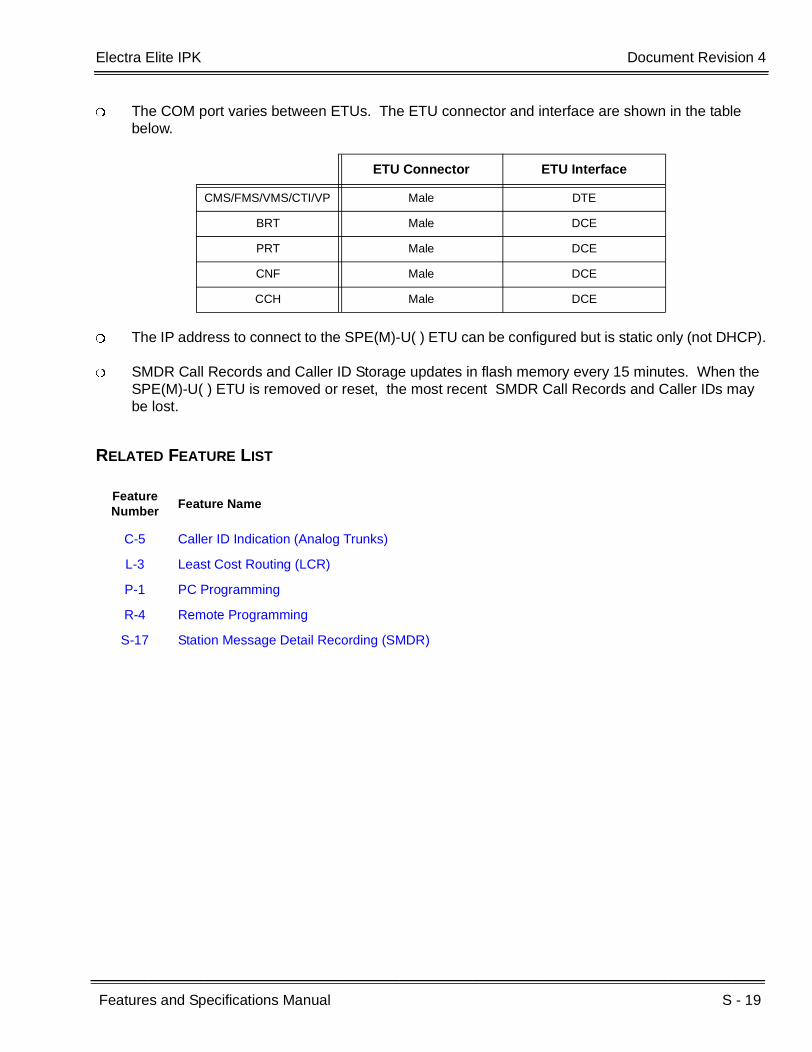
Electra Elite IPK Document Revision 4
Features and Specifications Manual S - 19
___________________________________________________________________________________
___________________________________________________________________________________
The COM port varies between ETUs. The ETU connector and interface are shown in the table below.
The IP address to connect to the SPE(M)-U( ) ETU can be configured but is static only (not DHCP).
SMDR Call Records and Caller ID Storage updates in flash memory every 15 minutes. When the SPE(M)-U( ) ETU is removed or reset, the most recent SMDR Call Records and Caller IDs may be lost.
RELATED FEATURE LIST
ETU Connector ETU Interface
CMS/FMS/VMS/CTI/VP Male DTE
BRT Male DCE
PRT Male DCE
CNF Male DCE
CCH Male DCE
Feature Number
Feature Name
C-5 Caller ID Indication (Analog Trunks)
L-3 Least Cost Routing (LCR)
P-1 PC Programming
R-4 Remote Programming
S-17 Station Message Detail Recording (SMDR)

S - 20 Single Point of Entry (SPE)
___________________________________________________________________________________
___________________________________________________________________________________Document Revision 4 Electra Elite IPK
GUIDE TO FEATURE PROGRAMMING
Orderand
ShortcutSystem Data Name
Memory Block
Function
1-8-07AttendantPage-Line
Key
1-8-08StationPage-
Line Key
+BS Card Interface Slot Assignment 7-1
+BS MIF (LCR) Assignment 7-3-1
+BS MIF (Caller ID) Assignment 7-3-4
+CSS COM Port Baud Rate Setting Assignment 1-8-35
+CSS COM Port Parity/Stop Bit Setting Assignment 1-8-36
+CSSModem Number for Remote Programming Assignment
1-8-38
+CSN Site Name Assignment 1-8-18
+CSP PC Programming Password Assignment 1-8-17

Features and Specifications Manual S - 21
___________________________________________________________________________________
___________________________________________________________________________________
Single Line Telephone Access S-7
FEATURE DESCRIPTION
The Expanded Port Package allows connection of 112 Electra Elite IPK system Single Line Telephones (SLTs). The Basic Port Package allows the connection of 24 Single Line Telephones. Single Line Telephone users can make CO/PBX calls, internal calls, and paging calls.
ENHANCEMENT(S)
Release 2000:
With R2000 or higher, a Single Line Telephone (SLT) can perform a Trunk-to-Trunk Transfer and a 1-terminal to 2-outside parties conference call.
Release 3000:
With R3000 or higher, Caller ID to Single Line Telephones is supported only for the incoming outside trunk calls (Loop Start, T1, ANI, ISDN, BRI, or PRI). A Send Caller ID Information to Single Line Telephones Class of Service is added.
Version 1.54 is required for SLIB(4)/SLIE(4)-U10 ETU to support Caller ID to Single Line Telephones.
SYSTEM AVAILABILITY
Terminal Type:
Single Line Telephones
Required Components:
SLI(4)/(8)-U( ) ETU, OPX(2)-U( ) ETU, or SLT(1)-U( ) ADP
AP(R)-R or AP(A)-R Unit connected to an Electra Elite IPK or Dterm Series i Digital Multiline Terminal (DTH/DTR)
APR-U or APA-U Unit connected to an Electra Elite Digital Multiline Terminal (DTU/DTP)
S - 22 Single Line Telephone Access
___________________________________________________________________________________
___________________________________________________________________________________Document Revision 4 Electra Elite IPK
OPERATING PROCEDURES
To originate internal calls:
1. Lift the handset, and wait for internal dial tone.
2. Dial the applicable station number.
3. Talk when called party answers.
To originate outside calls:
1. Lift the handset, and wait for internal dial tone.
2. Dial Trunk Access Code (default:I).
3. Dial the number of outside party.
4. Talk when the called party answers.
To answer outside or internal calls:
Lift the handset, and communicate.
To transfer an outside call or internal call with a call in progress:
1. Press the hookswitch momentarily, and wait for internal dial tone.
2. Dial the station number where call is to be transferred.
3. Hang up.
To perform a Trunk-to-Trunk Transfer with an outside call in progress (R2000 or higher):
1. Provide hookflash. The call is placed on Exclusive Hold. Receive internal dial tone.
2. Dial the Trunk Access Code for applicable trunk.
3. Dial the applicable number.
4. Hang up.

Electra Elite IPK Document Revision 4
Features and Specifications Manual S - 23
___________________________________________________________________________________
___________________________________________________________________________________
To initiate a 2 outside party Add-On conference using a Single Line Telephone with an outside call in progress (R2000 or higher):
1. Provide hookflash. The call is placed on Exclusive Hold. Receive internal dial tone.
2. Dial the Trunk Access Code for applicable trunk.
3. Dial the applicable number, and wait for the party to answer.
4. Provide hookflash again, and talk with both parties.
To access feature:
1. Lift the handset, and wait for internal dial tone.
2. Dial the Feature Access Code.
SERVICE CONDITIONS
General:
When using the DID Conversion Table, the Date and Time are provided by the IPK.
When using Analog lines, the Date and Time are provided by the CO provider.
Single Line Telephones provide a distinctive ringing pattern between CO/PBX incoming calls and internal calls.
Both DTMF type 2500 and Rotary type 500 Single Line Telephones can be used with the system.
Message Wait LEDs light when a message is sent to a Single Line Telephone with Message Wait LED [SLI(4)/(8)-U( ) ETU only].
A Single Line Telephone can be used to voice announce to a Multiline Terminal.
The system must be installed as Multifunction registration for Single Line Telephones to have dial access to outside lines.
Default Access Code 6# can be used to send a hookflash from a Single Line Telephone to an outside line.
After the PBR is released, DTMF tones from a Single Line Telephone are not detected by the system but are sent directly to the CO/PBX line.

S - 24 Single Line Telephone Access
___________________________________________________________________________________
___________________________________________________________________________________Document Revision 4 Electra Elite IPK
When Data Line Security is assigned for a Single Line Telephone, override tones are denied to this station.
When a Single Line Telephone is called, PBR is not connected to that Single Line Telephone. Therefore, no features can be set.
Restrictions:
Internal Calls, Transferred calls, and K-CCIS calls do not support Caller ID on Single Line Telephones.
The SLT(1)-U( ) ADP or OPX(2)-U( ) ETU does not support Message Waiting.
The AP(A)-R Unit or APA-U Unit does not support ringing.
When a rotary type 500 Single Line Telephone is used, Access Codes using # and must be changed to numerical digits because this telephone does not support these digits.
Most Feature Access Codes can be used from a Single Line Telephone when allowed by Station Class of Service and applicable assignments.
An SLT cannot perform a Trunk-to-Trunk Transfer or support a 1 terminal - 2 outside parties conference call (R1700 or lower only).
An SLT connected to the AP(A)-R/AP(R)-R Unit or the APA-U/APR-U Unit cannot perform a Trunk-to-Trunk Transfer or support a 1 terminal - 2 outside parties conference call.
Caller ID Name to Single Line Telephone is NOT supported for ISDN (BRT/PRT) Trunks.
RELATED FEATURES LIST
Feature Number
Feature Name
A-7 Ancillary Device Connection
A-23 Automatic Number Indication (ANI) on T1
C-5 Caller ID Indication (Analog Trunks)
C-19 Class of Service
C-26 Cordless Telephone Connection

Electra Elite IPK Document Revision 4
Features and Specifications Manual S - 25
___________________________________________________________________________________
___________________________________________________________________________________
GUIDE TO FEATURE PROGRAMMING
Orderand
ShortcutSystem Data Name
Memory Block
Function
1-8-07AttendantPage-Line
Key
1-8-08StationPage-
Line Key
+BS Card Interface Slot Assignment 7-1
+BTI Voice Mail/SLT Selection 4-35
+BTI DTMF/DP SLT Type Selection 4-95
+BTI SLT Hookflash Assignment 4-24
+BTI Dial 1 (DP) Hookflash Selection 1-3-04
+BTI SLT Hookflash Signal Selection 1-3-02
+BTISLT or Automated Attendant/DISA to PBR Selection
1-8-01
+BTSClass of Service (Station) Feature Selection 2 1-8-08 4-3, 4-4,
5-7, 6-5, 7-1
+BTI First Digit PBR Release Time Selection 1-3-03
+BTI Hookflash Start Time Selection 1-3-05
+BTI Hookflash End Time Selection 1-3-06
+BTI Bounce Protect Time Selection 1-3-01
+BTT Station Name Assignment 4-18
+BTT Telephone to Tenant Assignment 4-09
+BTT SLT Data Line Security Assignment 4-90
+BTT CO/PBX Ring Assignment (Day Mode) 4-01
+BTT CO/PBX Ring Assignment (Night Mode) 4-02
+BCT DIT Assignment 3-42
+BCT ANA Assignment 3-43
When the system is at default this Memory Block must be programmed for the feature to be used.

S - 26 Single Line Telephone Access
___________________________________________________________________________________
___________________________________________________________________________________Document Revision 4 Electra Elite IPK
THIS PAGE INTENTIONALLY LEFT BLANK
Features and Specifications Manual S - 27
___________________________________________________________________________________
___________________________________________________________________________________
SLT Adapter S-8
FEATURE DESCRIPTION
The Single Line Telephone (SLT) Adapter allows a port of an ESIB(8)-U( ) or ESIE(8)-U( ) ETU to support a Single Line Telephone. A Single Line Telephone can be connected to the ESIB(8)-U( ) ETU using the SLT Adapter and 2-wire cable. Eight SLT(1)-U( ) ADP Single Line Telephone Adapters can be installed in the Electra Elite IPK system.
ENHANCEMENT(S)
Release 2000:
With R2000 or higher, an SLT connected to an SLT Adapter [SLT(1)-U( )] can perform a Trunk-to-Trunk Transfer and a 1-terminal to 2-outside parties conference call.
SYSTEM AVAILABILITY
Terminal Type:
Single Line Telephones
Required Components:
SLT(1)-U( ) ADP
OPERATING PROCEDURES
To originate internal calls:
1. Lift the handset, and wait for internal dial tone.
2. Dial the applicable internal number.
3. Talk when called party answers.

S - 28 SLT Adapter
___________________________________________________________________________________
___________________________________________________________________________________Document Revision 4 Electra Elite IPK
To originate outside calls:
1. Lift the handset, and wait for dial tone.
2. Dial Trunk Access Code (default: I).
3. Dial the number of outside party.
4. Talk when the called party answers.
To answer outside or internal calls:
Lift the handset, and talk.
To transfer an outside call or internal call with a call in progress:
1. Press the hookswitch momentarily, and wait for second dial tone.
2. Dial the station number where call is to be transferred.
3. Hang up.
To perform a Trunk-to-Trunk Transfer with an outside call in progress (R2000 or higher):
1. Provide hookflash. The call is placed on Exclusive Hold. Receive internal dial tone.
2. Dial the Trunk Access Code for the applicable trunk.
3. Dial the applicable number.
4. Hang up.
To initiate a 2-outside party Add-On conference using an SLT with an outside call in progress (R2000 or higher):
1. Provide hookflash. The call is placed on Exclusive Hold. Receive internal dial tone.
2. Dial the Trunk Access Code for the applicable trunk.

Electra Elite IPK Document Revision 4
Features and Specifications Manual S - 29
___________________________________________________________________________________
___________________________________________________________________________________
3. Dial the applicable number, and wait for the party to answer.
4. Provide hookflash again, and speak with both parties.
To access the feature:
1. Lift the handset, and wait for internal dial tone.
2. Dial the applicable Feature Access Code.
SERVICE CONDITIONS
General:
A maximum of eight SLT(1)-U( ) ADPs can be used in the Electra Elite IPK system.
Dial Pulse and Dual-Tone Multifrequency Single Line Telephones are supported.
Restrictions:
The SLT(1)-U( ) ADP does not support voice mail.
Message Waiting LED is not supported.
An SLT connected to an SLT Adapter [SLT(1)-U( ) ADP] cannot perform a Trunk-to-Trunk Transfer or support a 1-terminal to 2-outside party conference call (R1700 or lower).
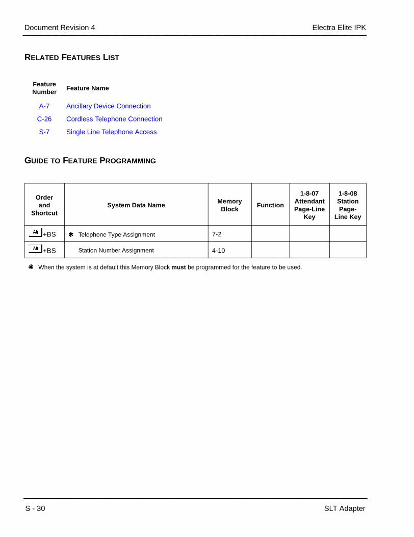
S - 30 SLT Adapter
___________________________________________________________________________________
___________________________________________________________________________________Document Revision 4 Electra Elite IPK
RELATED FEATURES LIST
GUIDE TO FEATURE PROGRAMMING
Feature Number
Feature Name
A-7 Ancillary Device Connection
C-26 Cordless Telephone Connection
S-7 Single Line Telephone Access
Orderand
ShortcutSystem Data Name
Memory Block
Function
1-8-07AttendantPage-Line
Key
1-8-08StationPage-
Line Key
+BS Telephone Type Assignment 7-2
+BS Station Number Assignment 4-10
When the system is at default this Memory Block must be programmed for the feature to be used.

Features and Specifications Manual S - 31
___________________________________________________________________________________
___________________________________________________________________________________
SLT Timed Alarm S-9
FEATURE DESCRIPTION
A Timed Alarm (reminder) may be set at any Single Line Telephone. At a programmed time, the system automatically calls the Single Line Telephone station user to indicate a scheduled action.
SYSTEM AVAILABILITY
Terminal Type:
All Single Line Telephones connected to an SLI(8)-U( ) ETU.
Required Components:
Any Single Line Telephone port
OPERATING PROCEDURES
To set Timed Alarm using a Single Line Telephone:
1. Lift the handset, and wait for internal dial tone.
2. Dial the Timed Alarm set/cancel Access Code X (not assigned at default).
3. Enter time for the alarm (24-hour format in 5-minute increments).
4. Restore the handset.
To cancel Timed Alarm using a Single Line Telephone:
1. Lift the handset, and wait for internal dial tone.
2. Dial Timed Alarm set/cancel Access Code X (not assigned at default).
3. Restore the handset.

S - 32 SLT Timed Alarm
___________________________________________________________________________________
___________________________________________________________________________________Document Revision 4 Electra Elite IPK
To cancel Timed Alarm using Attendant position:
1. Press A .
2. Dial EH.
3. Press A .
To set Timed Alarm for a Single Line Telephone using a Multiline Terminal (Attendant Position only):
1. Lift the handset or press E , and wait for internal dial tone.
2. Dial the Timed Alarm set/cancel to Single Line Telephone Access Code X (not assigned at default).
3. Dial the Single Line Telephone station number.
4. Enter time to set the alarm (24-hour format in 5-minute increments).
5. Restore the handset.
To cancel Timed Alarm for a Single Line Telephone using a Multiline Terminal (Attendant Position only):
1. Lift the handset or press E , and wait for internal dial tone.
2. Dial the Timed Alarm set/cancel to Single Line Telephone Access Code X (not assigned at default).
3. Dial the Single Line Telephone station number.
4. Dial time as II:II.
5. Restore the handset.

Electra Elite IPK Document Revision 4
Features and Specifications Manual S - 33
___________________________________________________________________________________
___________________________________________________________________________________
SERVICE CONDITIONS
General:
Timed Alarm must be set in five-minute increments for SLTs using a 24-hour format. For example: 12:10, 12:15,...23:55.
A Timed Alarm rings for four minutes when not answered.
When Timed Alarm is answered, the user hears Music On Hold.
SLT Timed Alarm must be set daily.
GUIDE TO FEATURE PROGRAMMING
Orderand
ShortcutSystem Data Name
Memory Block
Function
1-8-07Attendant
Page-Line Key
1-8-08StationPage-
Line Key
+BTS Class of Service (Attendant) Feature Selection 1 1-8-07 2-1
+BTS Class of Service (Station) Feature Selection 2 1-8-08 1-6
+BTT Station to Class of Service Feature Assignment 4-17
+BAAccess Code (1-, 2-, or 3-Digit) Assignment 1-1-46/47/
48044~046,

S - 34 SLT Timed Alarm
___________________________________________________________________________________
___________________________________________________________________________________Document Revision 4 Electra Elite IPK
THIS PAGE INTENTIONALLY LEFT BLANK

Features and Specifications Manual S - 35
___________________________________________________________________________________
___________________________________________________________________________________
Softkeys S-10
FEATURE DESCRIPTION
The Electra Elite IPK system provides softkeys on all display Electra Elite IPK (DTH), Dterm Series i (DTR), Electra Elite (DTU), or Dterm Series E (DTP) Multiline Terminals. Currently Speed Dial Scrolling Directories, and EliteMail Digital Voice Mail systems make extensive use of these keys to guide a station user effortlessly through difficult-to-use feature operations.
ENHANCEMENT(S)
R4000 or higher is required to support Interactive Softkeys.
SYSTEM AVAILABILITY
Terminal Type:
DTU/DTP or DTH/DTR Multiline Terminal with LCD
Required Components:
None
OPERATING PROCEDURES
None

S - 36 Softkeys
___________________________________________________________________________________
___________________________________________________________________________________Document Revision 4 Electra Elite IPK
INTERACTIVE SOFTKEYS (R4000 OR HIGHER)
Interactive Softkeys change state based on the following conditions of the Display Terminal.
On-Hook – Idle
Call Origination
Conversation Mode
Incoming Call State
On-Hook – Idle
Call Origination
Status Page 1 Softkeys Page 2 Softkeys
Idle MIC SYS. STA MORE DND CFA CFB/NA MORE
Status Page 1 Softkeys Page 2 Softkeys
ICM Calling RING VOICE
ICM Calling – Call Waiting Tone
CBR ACB T.O. MORE V.O. STEP MORE
ICM Calling – Busy* RECALL
ICM Calling – Voice Call On Hold
RING VOICE QVM
ICM Calling – CWT Call On Hold
QVM T.O. V.O. MORE CBR ACB STEP MORE
ICM Calling – Busy Call On Hold*
RECALL
CO Calling – NormalAUTO-RD
CO Calling – All Trunks Busy
T.Q.
* Call Control does not allow any options in this state
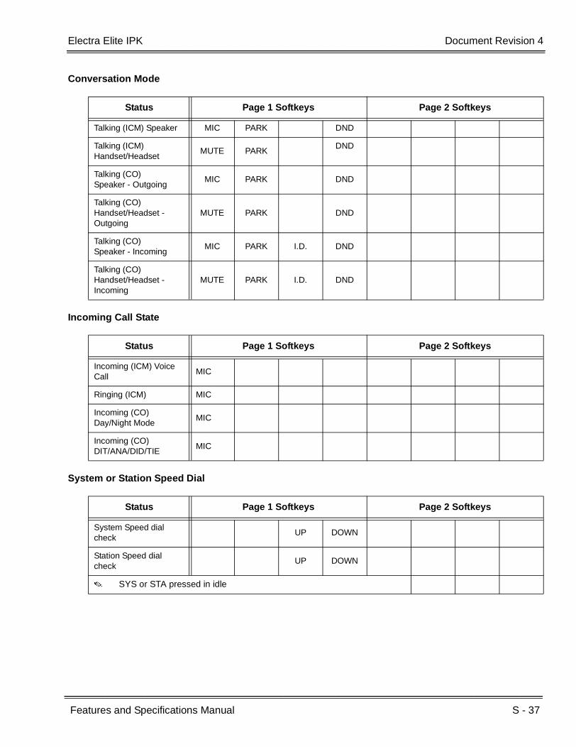
Electra Elite IPK Document Revision 4
Features and Specifications Manual S - 37
___________________________________________________________________________________
___________________________________________________________________________________
Conversation Mode
Incoming Call State
System or Station Speed Dial
Status Page 1 Softkeys Page 2 Softkeys
Talking (ICM) Speaker MIC PARK DND
Talking (ICM) Handset/Headset
MUTE PARK DND
Talking (CO)Speaker - Outgoing
MIC PARK DND
Talking (CO)Handset/Headset - Outgoing
MUTE PARK DND
Talking (CO)Speaker - Incoming
MIC PARK I.D. DND
Talking (CO)Handset/Headset - Incoming
MUTE PARK I.D. DND
Status Page 1 Softkeys Page 2 Softkeys
Incoming (ICM) Voice Call
MIC
Ringing (ICM) MIC
Incoming (CO)Day/Night Mode
MIC
Incoming (CO)DIT/ANA/DID/TIE
MIC
Status Page 1 Softkeys Page 2 Softkeys
System Speed dial check
UP DOWN
Station Speed dial check
UP DOWN
SYS or STA pressed in idle
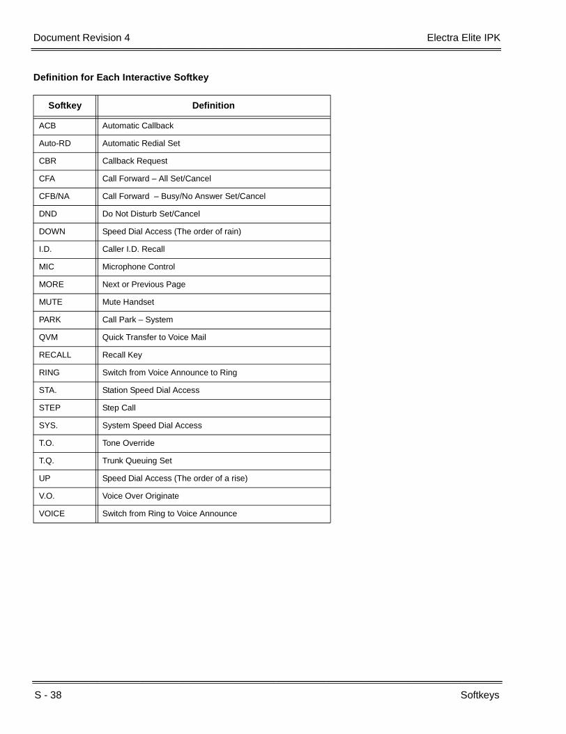
S - 38 Softkeys
___________________________________________________________________________________
___________________________________________________________________________________Document Revision 4 Electra Elite IPK
Definition for Each Interactive Softkey
Softkey Definition
ACB Automatic Callback
Auto-RD Automatic Redial Set
CBR Callback Request
CFA Call Forward – All Set/Cancel
CFB/NA Call Forward – Busy/No Answer Set/Cancel
DND Do Not Disturb Set/Cancel
DOWN Speed Dial Access (The order of rain)
I.D. Caller I.D. Recall
MIC Microphone Control
MORE Next or Previous Page
MUTE Mute Handset
PARK Call Park – System
QVM Quick Transfer to Voice Mail
RECALL Recall Key
RING Switch from Voice Announce to Ring
STA. Station Speed Dial Access
STEP Step Call
SYS. System Speed Dial Access
T.O. Tone Override
T.Q. Trunk Queuing Set
UP Speed Dial Access (The order of a rise)
V.O. Voice Over Originate
VOICE Switch from Ring to Voice Announce

Electra Elite IPK Document Revision 4
Features and Specifications Manual S - 39
___________________________________________________________________________________
___________________________________________________________________________________
SERVICE CONDITIONS
General:
Scrolling Directories, Elite ACD Plus, and Voice Mail applications supported by the CTI/VP, FMS, or VMS ETU currently use softkeys.
For more detailed operation for each Interactive Softkey, refer to Features and Specifications Manual for the related feature.
Restrictions:
R4000 or higher is required to support the Interactive Softkeys.
Interactive Softkeys are not available when an ACD Plus or Q-Master Agent or Supervisor is logged on.
RELATED FEATURES LIST
Feature Number
Feature Name
A-19 Automatic Callback
A-24 Automatic Redial
C-4 Callback Request
C-5 Caller ID Indication (Analog Trunks)
C-7 Call Forward – All Call
C-8 Call Forward – Busy/No Answer
C-13 Call Monitoring
C-14 Call Park – System
C-19 Class of Service
D-15 Do Not Disturb (DND)
H-1 Handset Mute
I-5 Internal Voice/Tone Signaling
M-3 Microphone Control
Q-1 Quick Transfer to Voice Mail
R-1 Recall Key
S-11 Speed Dial – Station
S-13 Speed Dial – System
S-22 Step Call

S - 40 Softkeys
___________________________________________________________________________________
___________________________________________________________________________________Document Revision 4 Electra Elite IPK
T-5 Tone Override
T-6 Trunk Queuing
V-4 Voice Over Split
Orderand
ShortcutSystem Data Name
Memory Block
Function
1-8-07AttendantPage-Line
Key
1-8-08StationPage-
Line Key
+BTS Class of Service (Station) Feature Selection 2 1-8-08 4-3, 4-4,
5-7, 6-5, 7-1,7-5
When the system is at default this Memory Block must be programmed for the feature to be used.
Feature Number
Feature Name
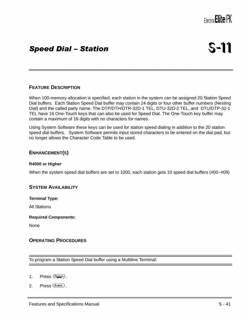
Features and Specifications Manual S - 41
___________________________________________________________________________________
___________________________________________________________________________________
Speed Dial – Station S-11
FEATURE DESCRIPTION
When 100-memory allocation is specified, each station in the system can be assigned 20 Station Speed Dial buffers. Each Station Speed Dial buffer may contain 24 digits or four other buffer numbers (Nesting Dial) and the called party name. The DTP/DTH/DTR-32D-1 TEL, DTU-32D-2 TEL, and DTU/DTP-32-1 TEL have 16 One-Touch keys that can also be used for Speed Dial. The One-Touch key buffer may contain a maximum of 16 digits with no characters for names.
Using System Software these keys can be used for station speed dialing in addition to the 20 station speed dial buffers. System Software permits input stored characters to be entered on the dial pad, but no longer allows the Character Code Table to be used.
ENHANCEMENT(S)
R4000 or Higher
When the system speed dial buffers are set to 1000, each station gets 10 speed dial buffers (#00~#09)
SYSTEM AVAILABILITY
Terminal Type:
All Stations
Required Components:
None
OPERATING PROCEDURES
To program a Station Speed Dial buffer using a Multiline Terminal:
1. Press A .
2. Press B .
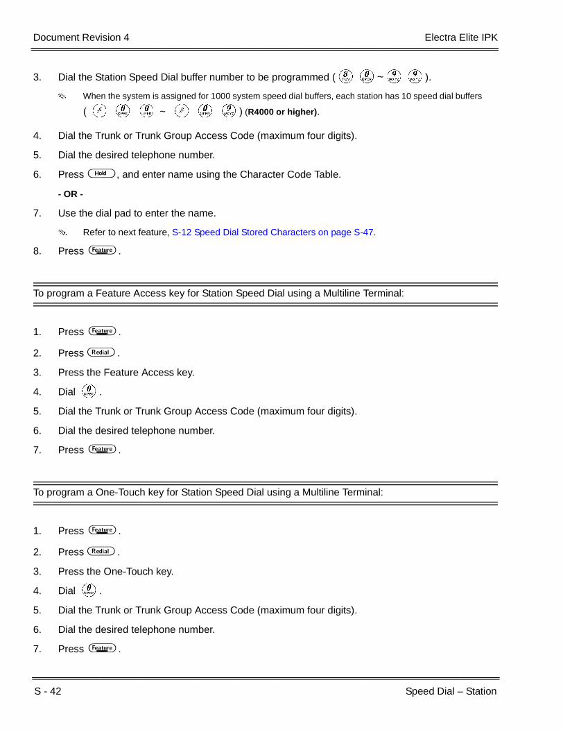
S - 42 Speed Dial – Station
___________________________________________________________________________________
___________________________________________________________________________________Document Revision 4 Electra Elite IPK
3. Dial the Station Speed Dial buffer number to be programmed (HK~II).
When the system is assigned for 1000 system speed dial buffers, each station has 10 speed dial buffers
( L K K ~ L K I) (R4000 or higher).
4. Dial the Trunk or Trunk Group Access Code (maximum four digits).
5. Dial the desired telephone number.
6. Press H , and enter name using the Character Code Table.
- OR -
7. Use the dial pad to enter the name.
Refer to next feature, S-12 Speed Dial Stored Characters on page S-47.
8. Press A .
To program a Feature Access key for Station Speed Dial using a Multiline Terminal:
1. Press A .
2. Press B .
3. Press the Feature Access key.
4. Dial K.
5. Dial the Trunk or Trunk Group Access Code (maximum four digits).
6. Dial the desired telephone number.
7. Press A .
To program a One-Touch key for Station Speed Dial using a Multiline Terminal:
1. Press A .
2. Press B .
3. Press the One-Touch key.
4. Dial K.
5. Dial the Trunk or Trunk Group Access Code (maximum four digits).
6. Dial the desired telephone number.
7. Press A .
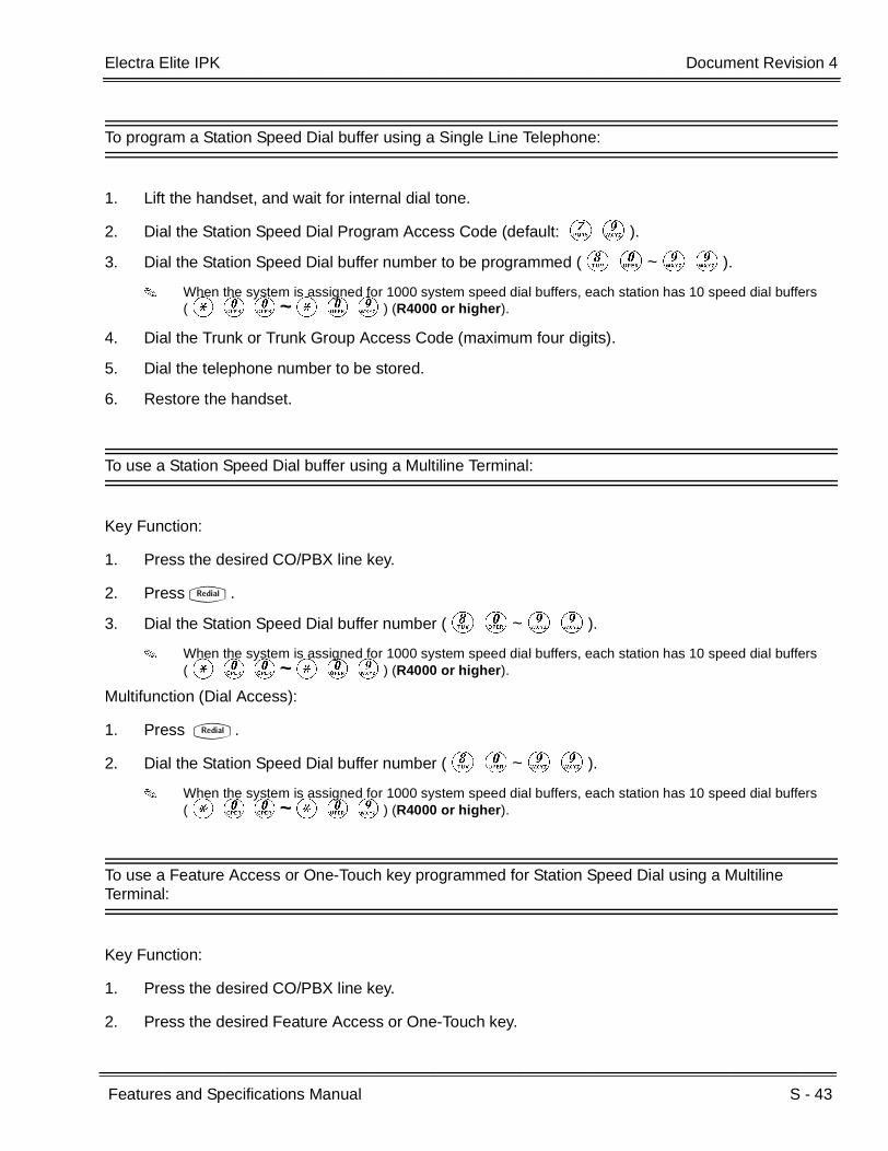
Electra Elite IPK Document Revision 4
Features and Specifications Manual S - 43
___________________________________________________________________________________
___________________________________________________________________________________
To program a Station Speed Dial buffer using a Single Line Telephone:
1. Lift the handset, and wait for internal dial tone.
2. Dial the Station Speed Dial Program Access Code (default: GI).
3. Dial the Station Speed Dial buffer number to be programmed (HK~II).
When the system is assigned for 1000 system speed dial buffers, each station has 10 speed dial buffers (JKK~JKI) (R4000 or higher).
4. Dial the Trunk or Trunk Group Access Code (maximum four digits).
5. Dial the telephone number to be stored.
6. Restore the handset.
To use a Station Speed Dial buffer using a Multiline Terminal:
Key Function:
1. Press the desired CO/PBX line key.
2. PressQ.
3. Dial the Station Speed Dial buffer number (HK~II).
When the system is assigned for 1000 system speed dial buffers, each station has 10 speed dial buffers (JKK~JKI) (R4000 or higher).
Multifunction (Dial Access):
1. Press Q.
2. Dial the Station Speed Dial buffer number (HK~II).
When the system is assigned for 1000 system speed dial buffers, each station has 10 speed dial buffers (JKK~JKI) (R4000 or higher).
To use a Feature Access or One-Touch key programmed for Station Speed Dial using a Multiline Terminal:
Key Function:
1. Press the desired CO/PBX line key.
2. Press the desired Feature Access or One-Touch key.

S - 44 Speed Dial – Station
___________________________________________________________________________________
___________________________________________________________________________________Document Revision 4 Electra Elite IPK
Multifunction (Dial Access):
Press the desired Feature Access or One-Touch key.
To use a Station Speed Dial Buffer using a Single Line Telephone:
Multifunction (Dial Access) only:
1. Lift the handset, and wait for internal dial tone.
2. Dial the Station Speed Dial Access Code (default: GG).
3. Dial the Station Speed Dial buffer number (HK~II).
When the system is assigned for 1000 system speed dial buffers, each station has 10 speed dial buffers (JKK~JKI) (R4000 or higher).
4. Talk with the called party.
To program the Station Speed Dial with 1000 System Speed Dials using a Multiline Terminal (R4000 or higher):
1. Press A .
2. Press B .
3. Dial the Speed Dial buffer number to be programmed (use L KK~ LKI.
4. Dial the Trunk or Trunk Group Access Code (maximum four digits).
5. Dial the desired telephone number.
To Confirm Speed Dial using a Multiline Terminal:
1. Press D .
2. Press B .
3. Dial the Speed Dial buffer number to be confirmed (HK~II).
When the system is assigned for 1000 system speed dial buffers, each station has 10 speed dial buffers (JKK~JKI) (R4000 or higher).

Electra Elite IPK Document Revision 4
Features and Specifications Manual S - 45
___________________________________________________________________________________
___________________________________________________________________________________
SERVICE CONDITIONS
General:
A maximum of 24 digits can be programmed for a Speed Dial buffer.
A maximum of 16 Feature Access keys per station can be programmed on unused line keys. A maximum of 16 digits can be programmed in each Feature Access key.
A pause, , and # may be programmed in a Multiline Terminal Station Speed Dial buffer. Each item is counted as a digit; however, the Trunk and Trunk Group Access Code do not count as digits.
A pause and hookflash can be programmed in a Single Line Telephone Station Speed Dial buffer, but only when using the Electra Elite System Program Technician Software.
Pauses stored in systems with the Least Cost Routing (LCR) feature may cause the MIFM-U( ) ETU with KMM(1.0)U to seize a Least Cost Route because the pauses may be considered digits dialed. In systems using LCR, pauses should be programmed as part of extra codes in the Extra Code Add Table.
The built-in battery backup on the CPUI( )-U( ) ETU for Electra Elite IPK retains Station Speed Dial memories when power fails.
To verify Station Speed Dial buffer contents on a Multiline Terminal with an LCD display, press the Conference key, then the Redial key, and dial the Station Speed Dial buffer (80~99).
With R4000 or Higher and the system set to 1000 speed dial buffers, dial #00~#09 for station buffers.
To verify Station Speed Dial buffer contents programmed on a Feature Access or One-Touch key on a Multiline Terminal with an LCD display, press the Feature key and then press the Feature Access or One-Touch key.
Multiline Terminal users may access two or more Station Speed Dial buffers using Consecutive Speed Dial.
Restrictions:
One-Touch keys programmed as Station Speed Dial cannot have a name stored with the number to dial.
A maximum of 13 characters can be entered for the name.
A maximum of 16 digits can be programmed for a One-Touch key.

S - 46 Speed Dial – Station
___________________________________________________________________________________
___________________________________________________________________________________Document Revision 4 Electra Elite IPK
RELATED FEATURES LIST
GUIDE TO FEATURE PROGRAMMING
Feature Number
Feature Name
C-25 Consecutive Speed Dial
F-2 Feature Access – User Programmable
N-2 Nesting Dial
S-12 Speed Dial Stored Characters
S-13 Speed Dial – System
Orderand
ShortcutSystem Data Name
Memory Block
Function
1-8-07AttendantPage-Line
Key
1-8-08StationPage-
Line Key
+BE Speed Dial Buffer Allocation 1-1-35
+BE Speed Dial Number/Name Display Selection 1-1-33
+BTM Line Key Selection for Telephone Mode 4-12
+BAAccess Code (1-, 2-, or 3-Digit) Assignment 1-1-46/47/
48090, 095

Features and Specifications Manual S - 47
___________________________________________________________________________________
___________________________________________________________________________________
Speed Dial Stored Characters S-12
FEATURE DESCRIPTION
Speed Dial buffers may contain 24 digits. When 100-memories (80 System Speed Dial buffers and 20 Station Speed dial buffers) are allocated, a maximum of 13 characters can be entered for the name. When 1000-memories are allocated, a maximum of 12 characters can be entered for the name.
System Software permits input stored characters to be entered on the dial pad, but no longer allows use of the Character Code Table.
SYSTEM AVAILABILITY
Terminal Type:
All Display Multiline Terminals
Required Components:
None
OPERATING PROCEDURES
To program a Station Speed Dial buffer with stored characters:
1. Press A .
2. Press B .
3. Dial the Station Speed Dial buffer number to be programmed (HK~II).
4. Dial the Trunk or Trunk Group Access Code (maximum four digits).
5. Dial the desired telephone number.
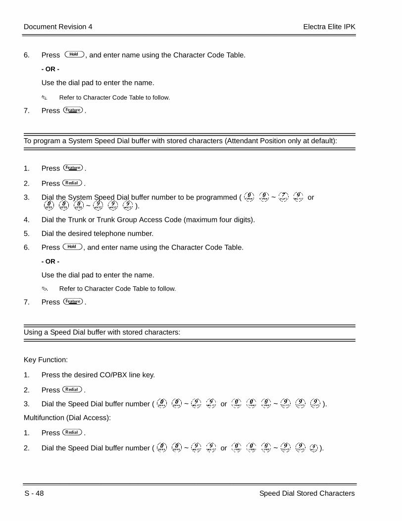
S - 48 Speed Dial Stored Characters
___________________________________________________________________________________
___________________________________________________________________________________Document Revision 4 Electra Elite IPK
6. Press H , and enter name using the Character Code Table.
- OR -
Use the dial pad to enter the name.
Refer to Character Code Table to follow.
7. Press A .
To program a System Speed Dial buffer with stored characters (Attendant Position only at default):
1. Press A .
2. Press B .
3. Dial the System Speed Dial buffer number to be programmed (KK~GI or KKK~III).
4. Dial the Trunk or Trunk Group Access Code (maximum four digits).
5. Dial the desired telephone number.
6. Press H , and enter name using the Character Code Table.
- OR -
Use the dial pad to enter the name.
Refer to Character Code Table to follow.
7. Press A .
Using a Speed Dial buffer with stored characters:
Key Function:
1. Press the desired CO/PBX line key.
2. Press B .
3. Dial the Speed Dial buffer number (KK~II or KKK~III).
Multifunction (Dial Access):
1. Press B .
2. Dial the Speed Dial buffer number (KK~II or KKK~III).

Electra Elite IPK Document Revision 4
Features and Specifications Manual S - 49
___________________________________________________________________________________
___________________________________________________________________________________
Using the Feature Access key for Station Speed Dial with stored characters:
Key Function:
1. Press the desired CO/PBX line key.
2. Press the desired Feature Access key.
Multifunction (Dial Access):
Press the desired Feature Access key.
SERVICE CONDITIONS
General:
When programming Feature Access or One-Touch keys, the Conference key can be used to backspace and erase an entry.
Stored characters can only be entered for outside line numbers.
Restrictions:
One-Touch keys, programmed as Station Speed Dial, cannot have a name stored with the number to dial.
RELATED FEATURES LIST
Feature Number
Feature Name
F-2 Feature Access – User Programmable
N-2 Nesting Dial
S-11 Speed Dial – Station
S-13 Speed Dial – System

S - 50 Speed Dial Stored Characters
___________________________________________________________________________________
___________________________________________________________________________________Document Revision 4 Electra Elite IPK
GUIDE TO FEATURE PROGRAMMING
CHARACTER CODE TABLE
Orderand
ShortcutSystem Data Name
Memory Block
Function
1-8-07AttendantPage-Line
Key
1-8-08StationPage-
Line Key
+BE Speed Dial Number/Name Display Selection 1-1-33
+BE Speed Dial Buffer Allocation 1-1-35
+BN System Speed Dial Display Assignment 2-07
System Data Input
Press 1 2 3 4 5 6 7 8 9 0 Redial
1st 1 A D G J M P T W 0 *
2nd @ B E H K N Q U X ! +
3rd [ C F I L O R V Y “ ,
4th a d g j m S t Z # -
5th ] b e h k n p u w $ .
6th ^ c f i l o q v x % /
7th 2 3 4 5 6 r 8 y & :
8th / To A To D To G To J To M s To T z ;
9th 7 9 ( <
10th | To P To W ) =
11th To 0 >
12th ?
13th To *
14th To 1
R Clears one character to the left.
# Used to move cursor to right.
Hold Space (MB3-00) Data Clear (except MB3-00)
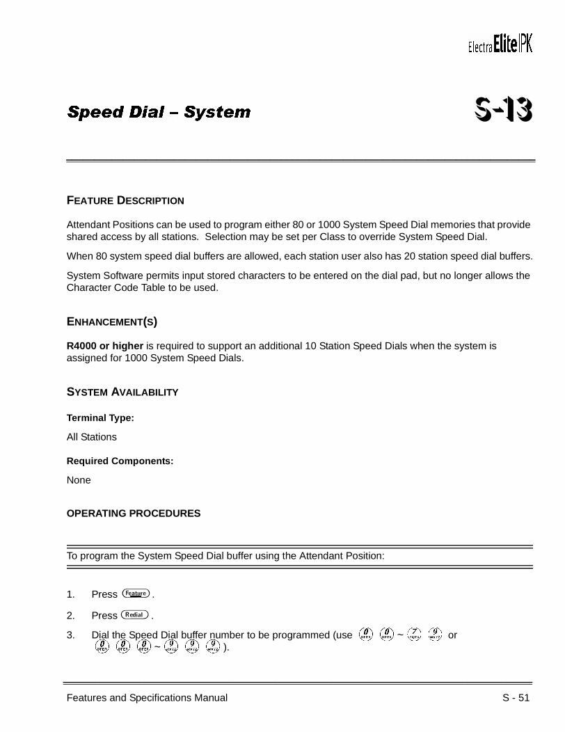
Features and Specifications Manual S - 51
___________________________________________________________________________________
___________________________________________________________________________________
Speed Dial – System S-13
FEATURE DESCRIPTION
Attendant Positions can be used to program either 80 or 1000 System Speed Dial memories that provide shared access by all stations. Selection may be set per Class to override System Speed Dial.
When 80 system speed dial buffers are allowed, each station user also has 20 station speed dial buffers.
System Software permits input stored characters to be entered on the dial pad, but no longer allows the Character Code Table to be used.
ENHANCEMENT(S)
R4000 or higher is required to support an additional 10 Station Speed Dials when the system is assigned for 1000 System Speed Dials.
SYSTEM AVAILABILITY
Terminal Type:
All Stations
Required Components:
None
OPERATING PROCEDURES
To program the System Speed Dial buffer using the Attendant Position:
1. Press A .
2. Press B .
3. Dial the Speed Dial buffer number to be programmed (use KK~GI or KKK~III).
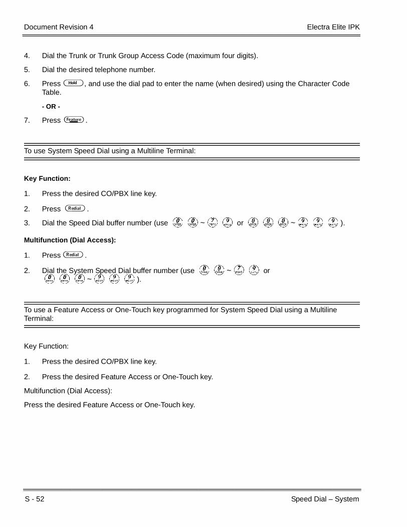
S - 52 Speed Dial – System
___________________________________________________________________________________
___________________________________________________________________________________Document Revision 4 Electra Elite IPK
4. Dial the Trunk or Trunk Group Access Code (maximum four digits).
5. Dial the desired telephone number.
6. Press H , and use the dial pad to enter the name (when desired) using the Character Code Table.
- OR -
7. Press A .
To use System Speed Dial using a Multiline Terminal:
Key Function:
1. Press the desired CO/PBX line key.
2. Press B .
3. Dial the Speed Dial buffer number (use KK~GI or KKK~III).
Multifunction (Dial Access):
1. Press B .
2. Dial the System Speed Dial buffer number (use KK~GI or KKK~III).
To use a Feature Access or One-Touch key programmed for System Speed Dial using a Multiline Terminal:
Key Function:
1. Press the desired CO/PBX line key.
2. Press the desired Feature Access or One-Touch key.
Multifunction (Dial Access):
Press the desired Feature Access or One-Touch key.

Electra Elite IPK Document Revision 4
Features and Specifications Manual S - 53
___________________________________________________________________________________
___________________________________________________________________________________
To use a System Speed Dial buffer using a Single Line Telephone:
Multifunction (Dial Access) only:
1. Lift the handset, and wait for internal dial tone.
2. Dial the Speed Dial Access Code (default: GF).
3. Dial the System Speed Dial buffer number (use KK~GI or
KKK~III.
4. Talk with called party.
SERVICE CONDITIONS
General:
When using 1000 System Speed Dial mode, buffers 900~999 cannot be restricted from any tenant.
System Speed Dial blocks can be shared by one or more tenants.
A maximum of 24 digits can be programmed in a System Speed Dial buffer.
A name can be entered with the number to be dialed when programming a System Speed Dial buffer. The name is displayed when the Speed Dial buffer is used.
A maximum of 13 characters using 80 System Speed Dial mode or 12 characters using 1000 System Speed Dial mode can be entered for the name.
A pause, hookflash, , and # may be programmed in a System Speed Dial buffer. Each item is counted as a digit, except the Trunk and Trunk Group Access Code.
The built-in battery backup on the CPUI( )-U( ) ETU retains System Speed Dial memories when power fails.
To verify System Speed Dial buffer contents on a Multiline Terminal with an LCD display, press the Conference key, then the Redial key, and dial the System Speed Dial buffer (use 00~79 or 000~999) (R3500 or lower).
Multiline Terminal users may access two or more System Speed Dial buffers by using Consecutive Speed Dial.
A pause is automatically inserted when a PBX Access Code with a pause specified by Memory Block 1-1-24 (PBX/CTX Access Code Assignment I) is entered in a System Speed Dial buffer.

S - 54 Speed Dial – System
___________________________________________________________________________________
___________________________________________________________________________________Document Revision 4 Electra Elite IPK
Pauses should not be stored in Speed Dial in systems with the Least Cost Routing (LCR) feature. These pauses may cause the MIFM-U( ) ETU with KMM(1.0)U to seize a Least Cost Route because the pauses may be considered digits dialed. In systems using the LCR feature, pauses should be programmed as part of extra codes in the Extra Code Add Table.
With R4000 or higher, when 1000 System Speed Dial buffers (000~999) are available, 10 additional Station Speed Dial buffers are available (#00~#09).
Memory Block 8-3 (Station Speed Dial Memory Clear) can be used to clear all Station Speed Dials.
Restrictions:
When 1000 System Speed Dial buffers (000~999) are available, Station Speed Dial buffers cannot be assigned (R3500 or lower).
RELATED FEATURES LIST
Feature Number
Feature Name
C-25 Consecutive Speed Dial
F-2 Feature Access – User Programmable
N-2 Nesting Dial
S-11 Speed Dial – Station
S-12 Speed Dial Stored Characters

Electra Elite IPK Document Revision 4
Features and Specifications Manual S - 55
___________________________________________________________________________________
___________________________________________________________________________________
GUIDE TO FEATURE PROGRAMMING
Orderand
ShortcutSystem Data Name
Memory Block
Function
1-8-07AttendantPage-Line
Key
1-8-08StationPage-
Line Key
+BE Speed Dial Buffer Allocation 1-1-35
+BE Speed Dial Number/Name Display Selection 1-1-33
+AC System Speed Dial Restriction by Tenant 1-1-18
+BTSClass of Service (Attendant) Feature Selection 1
1-8-07 1-3
+BTTStation to Class of Service Feature Assignment
4-17
+ACSystem Speed Dial Override by Class Selection
1-1-62
+BN System Speed Dial Display Assignment 2-07
+BAAccess Code (1-, 2-, or 3-Digit) Assignment 1-1-46/47/
48090, 095
S - 56 Speed Dial – System
___________________________________________________________________________________
___________________________________________________________________________________Document Revision 4 Electra Elite IPK
THIS PAGE INTENTIONALLY LEFT BLANK
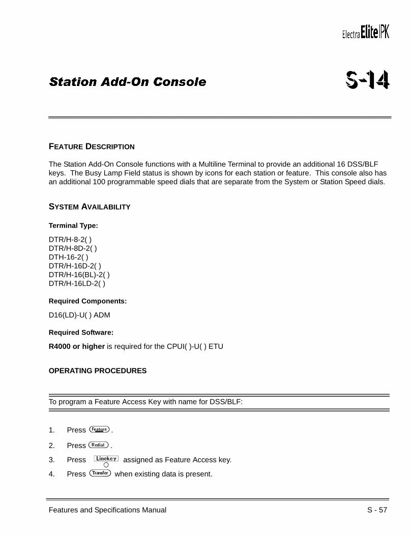
Features and Specifications Manual S - 57
___________________________________________________________________________________
___________________________________________________________________________________
Station Add-On Console S-14
FEATURE DESCRIPTION
The Station Add-On Console functions with a Multiline Terminal to provide an additional 16 DSS/BLF keys. The Busy Lamp Field status is shown by icons for each station or feature. This console also has an additional 100 programmable speed dials that are separate from the System or Station Speed dials.
SYSTEM AVAILABILITY
Terminal Type:
DTR/H-8-2( )DTR/H-8D-2( )DTH-16-2( )DTR/H-16D-2( )DTR/H-16(BL)-2( )DTR/H-16LD-2( )
Required Components:
D16(LD)-U( ) ADM
Required Software:
R4000 or higher is required for the CPUI( )-U( ) ETU
OPERATING PROCEDURES
To program a Feature Access Key with name for DSS/BLF:
1. Press A .
2. Press B .
3. Press Wassigned as Feature Access key.
4. Press G when existing data is present.

S - 58 Station Add-On Console
___________________________________________________________________________________
___________________________________________________________________________________Document Revision 4 Electra Elite IPK
5. Dial A.
6. Dial station number
7. Dial A(option, refer to note).
To switch the call from Voice to Tone or Tone to Voice.
8. Press H .
9. Press G when existing data is present.
10. Enter name using the dial pad.
11. Press A .
To program a Feature Access Key with Name for Station Speed Dial:
1. Press A .
2. Press B .
3. Press Wassigned as Feature Access key.
4. Press G when existing data is present.
5. Dial K.
6. Dial the Trunk or Trunk Group Access Code (4-digit maximum).
7. Dial Telephone number to be dialed.
8. Press H .
9. Press G when existing data is present.
10. Enter name using the dial pad.
11. Press A .
To program a Feature Access Key with Name for dial code feature:
1. Press A .
2. Press B .
3. Press Wassigned as Feature Access key.
4. Press G when existing data is present.
5. Dial A.
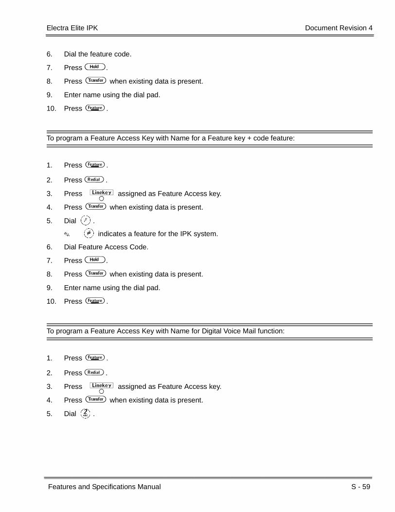
Electra Elite IPK Document Revision 4
Features and Specifications Manual S - 59
___________________________________________________________________________________
___________________________________________________________________________________
6. Dial the feature code.
7. Press H .
8. Press G when existing data is present.
9. Enter name using the dial pad.
10. Press A .
To program a Feature Access Key with Name for a Feature key + code feature:
1. Press A .
2. Press B .
3. Press Wassigned as Feature Access key.
4. Press G when existing data is present.
5. Dial L.
L indicates a feature for the IPK system.
6. Dial Feature Access Code.
7. Press H .
8. Press G when existing data is present.
9. Enter name using the dial pad.
10. Press A .
To program a Feature Access Key with Name for Digital Voice Mail function:
1. Press A .
2. Press B .
3. Press Wassigned as Feature Access key.
4. Press G when existing data is present.
5. Dial B.

S - 60 Station Add-On Console
___________________________________________________________________________________
___________________________________________________________________________________Document Revision 4 Electra Elite IPK
6. Dial Digital Voice Mail feature code.
Feature codes are:
KK Record
KA Pause
KB Rerecord
KC Erase
KD End
KE Urgent Page
KF Address
KG Live Monitor
7. Press H .
8. Press G when existing data is present.
9. Enter name using the dial pad.
10. Press A .
To program or use the Directory Feature:
Refer to the manual provided with each unit
SERVICE CONDITIONS
General:
When a user programs or modifies a Name for a Feature Access/One Touch key, changes are displayed in Memory Block 4-70 [LCD Line Key – Name Assignment (Station Add On Console)].
Restrictions:
The Add on Module (ADM) Directory (PC application) must be used to edit the directory database. Refer to the documentation provided with the D16(LD)-R( ) ADM unit.
The dialed # feature of the D16(LD)-R( ) ADM stores the last 15 calls made for the unit.
Memory Block 4-50 (Multiline Terminal Type Selection) must be set for the 16-key station when the D16(LD)-R( ) ADM is attached.
A maximum of 100 Directories can be stored in the D16(LD)-R( ) ADM.
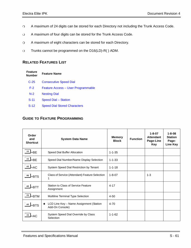
Electra Elite IPK Document Revision 4
Features and Specifications Manual S - 61
___________________________________________________________________________________
___________________________________________________________________________________
A maximum of 24 digits can be stored for each Directory not including the Trunk Access Code.
A maximum of four digits can be stored for the Trunk Access Code.
A maximum of eight characters can be stored for each Directory.
Trunks cannot be programmed on the D16(LD)-R( ) ADM.
RELATED FEATURES LIST
GUIDE TO FEATURE PROGRAMMING
Feature Number
Feature Name
C-25 Consecutive Speed Dial
F-2 Feature Access – User Programmable
N-2 Nesting Dial
S-11 Speed Dial – Station
S-12 Speed Dial Stored Characters
Orderand
ShortcutSystem Data Name
Memory Block
Function
1-8-07AttendantPage-Line
Key
1-8-08StationPage-
Line Key
+BE Speed Dial Buffer Allocation 1-1-35
+BE Speed Dial Number/Name Display Selection 1-1-33
+AC System Speed Dial Restriction by Tenant 1-1-18
+BTSClass of Service (Attendant) Feature Selection 1
1-8-07 1-3
+BTTStation to Class of Service Feature Assignment
4-17
+BTM Multiline Terminal Type Selection 4-50
+BTS LCD Line Key – Name Assignment (Station
Add-On Console)4-70
+ACSystem Speed Dial Override by Class Selection
1-1-62
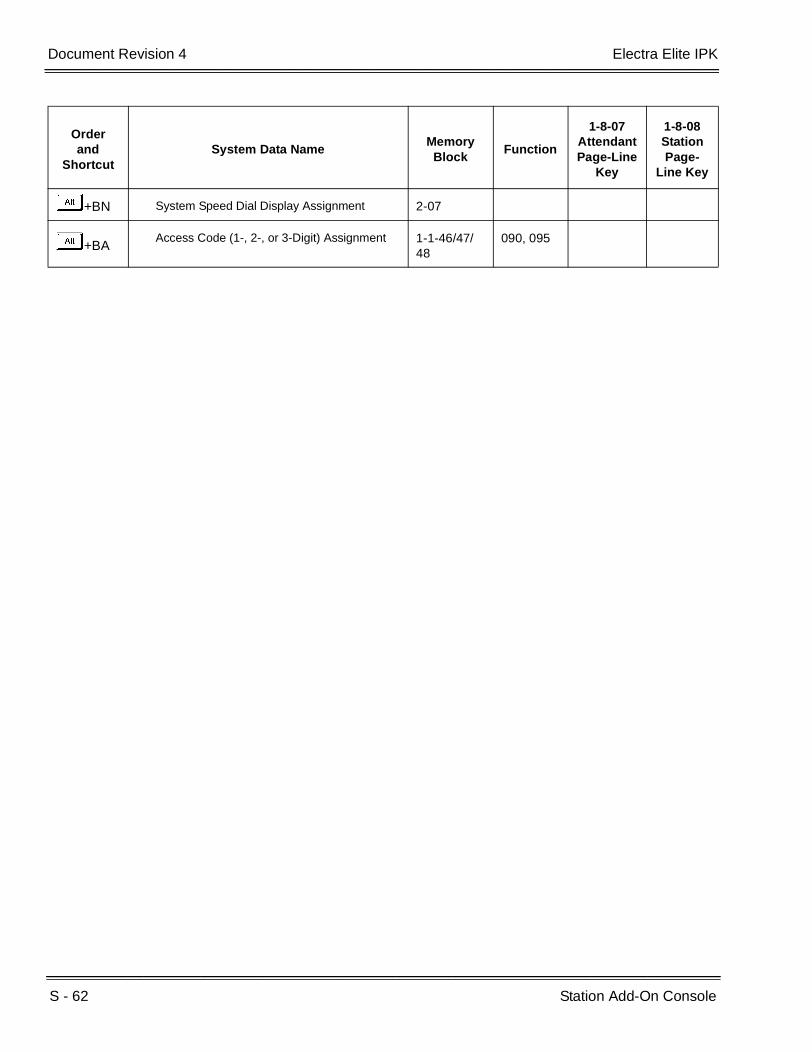
S - 62 Station Add-On Console
___________________________________________________________________________________
___________________________________________________________________________________Document Revision 4 Electra Elite IPK
+BN System Speed Dial Display Assignment 2-07
+BAAccess Code (1-, 2-, or 3-Digit) Assignment 1-1-46/47/
48090, 095
Orderand
ShortcutSystem Data Name
Memory Block
Function
1-8-07AttendantPage-Line
Key
1-8-08StationPage-
Line Key

Features and Specifications Manual S - 63
___________________________________________________________________________________
___________________________________________________________________________________
Station Camp-On S-15
FEATURE DESCRIPTION
Station Camp-On allows a call to be transferred to a busy station. When the station receiving the Camp-On tone becomes idle, the call rings and can be answered. After a programmed time, unanswered Camp-On calls recall to the station that initiated the Camp-On.
SYSTEM AVAILABILITY
Terminal Type:
All Stations
Required Components:
None
OPERATING PROCEDURES
To originate Station Camp-On from a Multiline Terminal with a call in progress:
1. Press G . The call is placed on Non-Exclusive Hold.
2. Dial the station number or press the designated DSS key programmed on a Flexible Line key or One-Touch key on the terminal. Receive call waiting tone.
3. Go on-hook.
4. After timeout, when the Camp-On remains unanswered, the line recalls, and the LED on the assigned CO/PBX line key returns to flashing green.
5. Press the CO/PBX line key with green LED, and go off-hook to return to the call.

S - 64 Station Camp-On
___________________________________________________________________________________
___________________________________________________________________________________Document Revision 4 Electra Elite IPK
To answer a Camp-On while engaged in a call:
1. Receive a camp-on tone. The CO/PBX line key LED flashes green.
2. Press the flashing F . The existing CO/PBX line call is automatically placed on hold, and the camp-on is answered.
3. Go on-hook. The transferred call rings.
4. Go off-hook or press F , and talk with the incoming caller.
To originate a Station Camp-On using a Single Line Telephone with a call in progress:
1. Press the hookswitch momentarily, and wait for second dial tone.
2. Dial the station number to where call is to be transferred.
3. Hang up.
SERVICE CONDITIONS
General:
When the Camp-On is placed after Tone Override, camp-on tone is provided.
Station and Attendant Camp-On Recall times can be assigned separately.
Camp-On Tone receive is assigned in Station Class of Service assignment.
Features and Specifications Manual S - 65
___________________________________________________________________________________
___________________________________________________________________________________
Station Hunt S-16
FEATURE DESCRIPTION
Station Hunt distributes internal and outside calls to multiple stations in a Station Hunt group. When a dialed station number programmed as an Intercom Master Hunt Number is busy, the call is forwarded to another station in that hunt group.
SYSTEM AVAILABILITY
Terminal Type:
All Stations
Required Components:
None
OPERATING PROCEDURES
To call a Station Hunt group from an internal station:
1. Lift the handset, and wait for internal dial tone.
2. Dial the station number of the desired hunt group.
3. Talk with the called party when answered.
To use this feature for an incoming internal, DIT/ANA, or Tie/DID call:
An incoming call to a station number programmed as an Intercom Master Hunt Number is sent to the first available station in the hunt group.

S - 66 Station Hunt
___________________________________________________________________________________
___________________________________________________________________________________Document Revision 4 Electra Elite IPK
SERVICE CONDITIONS
General:
A maximum of 120 stations in the expanded Electra Elite IPK, or 32 stations in the basic Electra Elite IPK can be assigned to a hunt group.
The Intercom Master Hunt Number is an actual station. When it is busy, the call is forwarded to the next programmed answering station.
Linear hunt (consecutively search from the lead station) is provided.
DIT/ANA calls to an Intercom Master Hunt Number follow the station hunt group assignment.
When a station number other than the Intercom Master Hunt Number in the hunt group is dialed directly, the hunt is not provided.
When an Intercom Master Hunt Number is set for Call Forward – All Call/Busy, incoming calls follow the Call Forward setting. When the Forward to Station is busy, the incoming calls follow the station hunt assignment.
An Intercom Master Hunt Number can be included in another station hunt group to chain together two Station Hunt groups.
These conditions cause a station in the hunt group to be skipped:
The station is busy.
Call Forward – All Call is set for that station.
The station is in DND Mode.
The station is off-line.
CO Ring transfers, DIT/ANA, Tie/DID, and internal calls to an Intercom Master Hunt Number do not hunt past an unanswered member of the hunt group.
When all hunt group stations are busy, the transferring caller hears call waiting tone. The call is camped on the Intercom Master Hunt Number and does not forward to other stations that become idle.
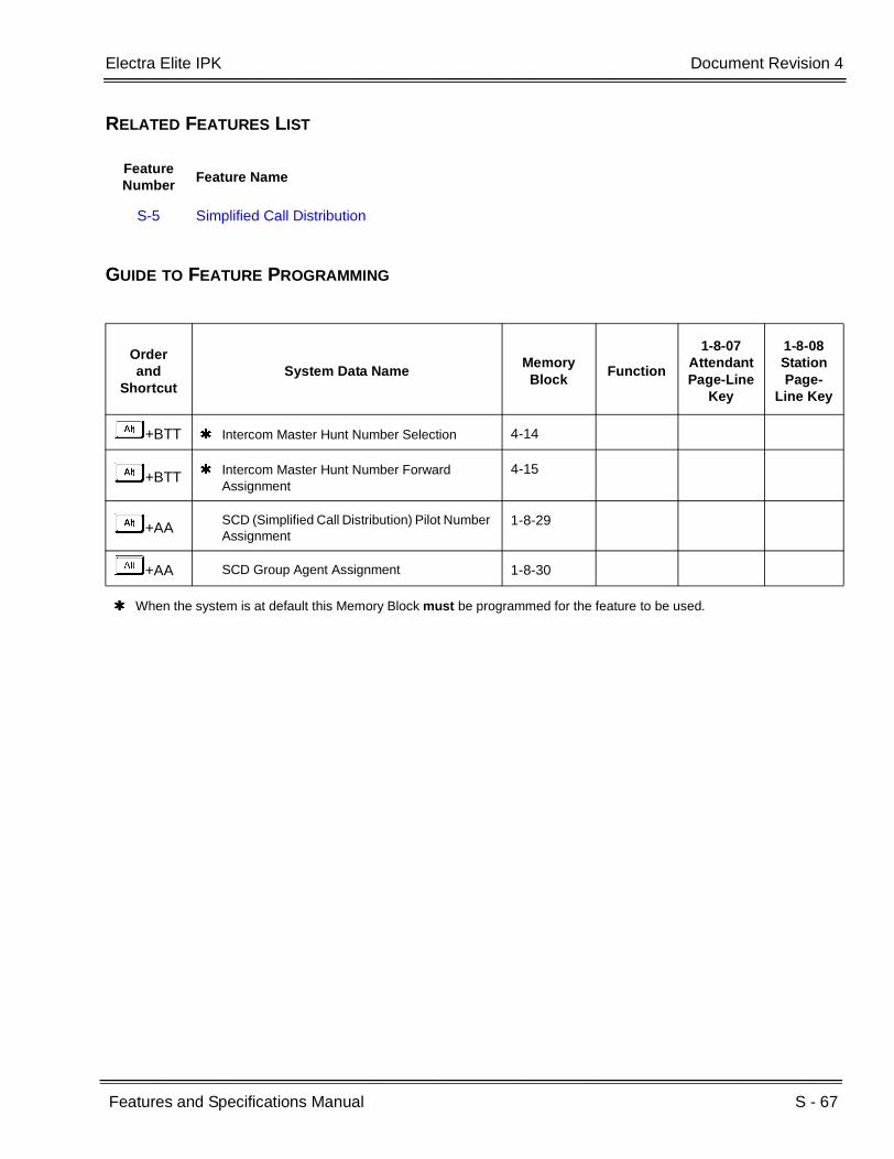
Electra Elite IPK Document Revision 4
Features and Specifications Manual S - 67
___________________________________________________________________________________
___________________________________________________________________________________
RELATED FEATURES LIST
GUIDE TO FEATURE PROGRAMMING
Feature Number
Feature Name
S-5 Simplified Call Distribution
Orderand
ShortcutSystem Data Name
Memory Block
Function
1-8-07AttendantPage-Line
Key
1-8-08StationPage-
Line Key
+BTT Intercom Master Hunt Number Selection 4-14
+BTT Intercom Master Hunt Number Forward Assignment
4-15
+AASCD (Simplified Call Distribution) Pilot Number Assignment
1-8-29
+AA SCD Group Agent Assignment 1-8-30
When the system is at default this Memory Block must be programmed for the feature to be used.

S - 68 Station Hunt
___________________________________________________________________________________
___________________________________________________________________________________Document Revision 4 Electra Elite IPK
THIS PAGE INTENTIONALLY LEFT BLANK
Features and Specifications Manual S - 69
___________________________________________________________________________________
___________________________________________________________________________________
Station Message Detail Recording (SMDR) S-17
FEATURE DESCRIPTION
An optional MIFM-U( ) ETU provides detailed outside call records of system telephone usage to support cost control by identifying telephone users, trunk usage, and digits dialed. SMDR enables connection of call accounting equipment to audit local and long distance telephone bills.
SYSTEM AVAILABILITY
Terminal Type:
All Multiline Terminals:
Incoming CO/PBX Call
Outgoing CO/PBX Call
Conference CO/PBX Call
Transferred CO/PBX Call
Required Components:
RS-232C compatible printer and serial data straight connection cable and/or a call accounting unit must be locally provided.
MIFM-U( ) ETU
- OR -
SPE(M)-U10 ETU
OPERATING PROCEDURES
None

S - 70 Station Message Detail Recording (SMDR)
___________________________________________________________________________________
___________________________________________________________________________________Document Revision 4 Electra Elite IPK
SERVICE CONDITIONS
General:
When the printer or other I/O device fails to operate, approximately 100 call records are saved in the MIFM-U( ) ETU buffer. When the buffer is full, the first call record is lost and the last call record is stored.
Call record data provides the Start Time, Trunk Number, Trunk Group, Type of Call, Station Number, Duration, Number Dialed, LCR, Calling Station Number, and Transferred Station Number.
The maximum digits allowed for output of a telephone number is 24.
When Printer is assigned, and a printer is not connected to the system, a PRINTER TROUBLE LCD indication and an audible alert tone are provided at the first two Multiline Terminals connected to the system (Stations 100 and 101). When an MIFM-U( ) ETU is not installed or disabled, no alarm indication is given.
When Caller ID is installed, SMDR prints the incoming caller telephone number when received from the Central Office.
Call records are not provided for internal calls.
Caller ID name is not printed on SMDR.
When the system automatically switches the clock for daylight saving time and a station is on a call, the duration of that call is invalid.
Restrictions:
When 5-, 6-, or 7-digit station numbers are used, only the last four digits of the extension number are printed by SMDR.
SMDR Print Formats:
Outgoing Call07/03/98 09:00 08-05-12 OG 123 A B C D E00:15:32 101028809727519000 G H
Outgoing Call07/03/98 09:00 08-05-12 OG 123 A B C D E00:15:32 101028809727519000 G H
Outgoing Call (LCR)07/03/98 09:00 08-05-12 OG 123 A B C D E

Electra Elite IPK Document Revision 4
Features and Specifications Manual S - 71
___________________________________________________________________________________
___________________________________________________________________________________
00:15:32 101028809727517000 G H LCR K
Incoming Call07/03/98 09:00 05-12 IC 123 A B C D E00:15:32 9727517000 G H
DISA (Both incoming and outgoing are printed. Format shown is printed when incoming callerhangs up first. Format is reversed when called party hangs up first.
07/03/98 09:00 05-12 IC 999 234 A B C D E F00:15:32 G D100 J07/03/98 09:00 08- 05-12 OG 999 A B C D E00:15:32 101028809787577000 G H1234567890 D100 I J
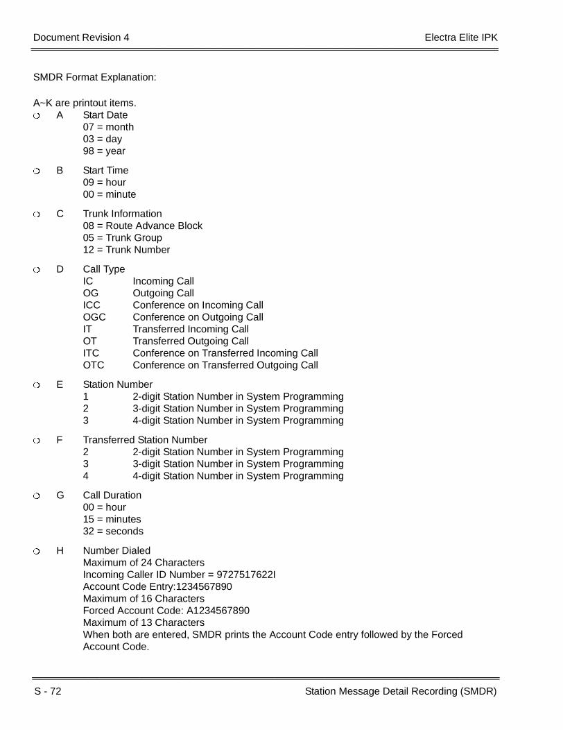
S - 72 Station Message Detail Recording (SMDR)
___________________________________________________________________________________
___________________________________________________________________________________Document Revision 4 Electra Elite IPK
SMDR Format Explanation:
A~K are printout items. A Start Date
07 = month03 = day98 = year
B Start Time09 = hour00 = minute
C Trunk Information08 = Route Advance Block05 = Trunk Group12 = Trunk Number
D Call TypeIC Incoming CallOG Outgoing CallICC Conference on Incoming CallOGC Conference on Outgoing CallIT Transferred Incoming CallOT Transferred Outgoing CallITC Conference on Transferred Incoming CallOTC Conference on Transferred Outgoing Call
E Station Number1 2-digit Station Number in System Programming2 3-digit Station Number in System Programming3 4-digit Station Number in System Programming
F Transferred Station Number2 2-digit Station Number in System Programming3 3-digit Station Number in System Programming4 4-digit Station Number in System Programming
G Call Duration00 = hour15 = minutes32 = seconds
H Number DialedMaximum of 24 CharactersIncoming Caller ID Number = 9727517622IAccount Code Entry:1234567890Maximum of 16 CharactersForced Account Code: A1234567890Maximum of 13 CharactersWhen both are entered, SMDR prints the Account Code entry followed by the Forced Account Code.
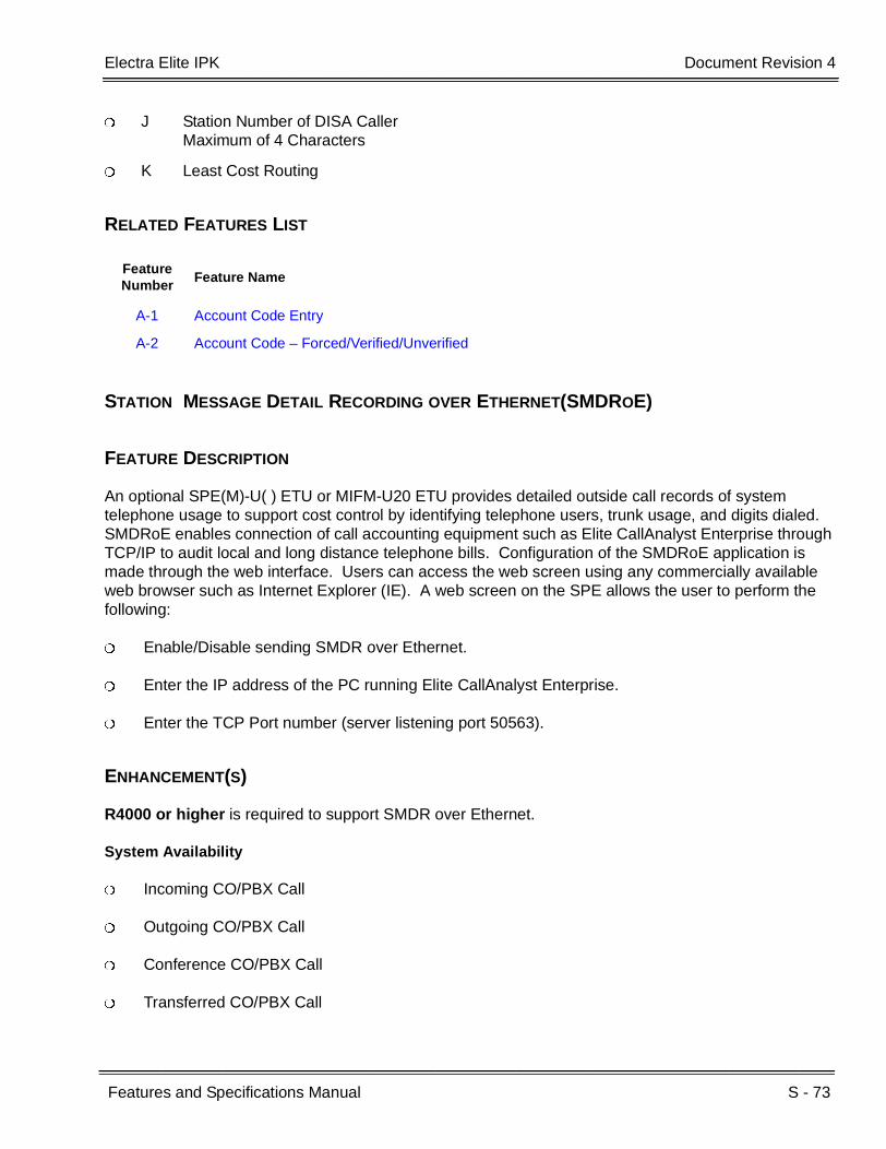
Electra Elite IPK Document Revision 4
Features and Specifications Manual S - 73
___________________________________________________________________________________
___________________________________________________________________________________
J Station Number of DISA CallerMaximum of 4 Characters
K Least Cost Routing
RELATED FEATURES LIST
STATION MESSAGE DETAIL RECORDING OVER ETHERNET(SMDROE)
FEATURE DESCRIPTION
An optional SPE(M)-U( ) ETU or MIFM-U20 ETU provides detailed outside call records of system telephone usage to support cost control by identifying telephone users, trunk usage, and digits dialed. SMDRoE enables connection of call accounting equipment such as Elite CallAnalyst Enterprise through TCP/IP to audit local and long distance telephone bills. Configuration of the SMDRoE application is made through the web interface. Users can access the web screen using any commercially available web browser such as Internet Explorer (IE). A web screen on the SPE allows the user to perform the following:
Enable/Disable sending SMDR over Ethernet.
Enter the IP address of the PC running Elite CallAnalyst Enterprise.
Enter the TCP Port number (server listening port 50563).
ENHANCEMENT(S)
R4000 or higher is required to support SMDR over Ethernet.
System Availability
Incoming CO/PBX Call
Outgoing CO/PBX Call
Conference CO/PBX Call
Transferred CO/PBX Call
Feature Number
Feature Name
A-1 Account Code Entry
A-2 Account Code – Forced/Verified/Unverified

S - 74 Station Message Detail Recording (SMDR)
___________________________________________________________________________________
___________________________________________________________________________________Document Revision 4 Electra Elite IPK
Required Components
TCP/IP connection from server side [(SPE(M)-U( ) or MIFM-U20 ETU)] to client side (PC).
MIFM-U20
- OR -
SPE(M)-U( ) ETU
OPERATING PROCEDURES
None
SERVICE CONDITIONS
General:
When SMDR is enabled and neither the printer nor SMDRoE client is connected, the SMDR call records are archived to Flash. The archive stores 200 SMDR records. When the buffer is full, the first call record is lost, and the last call record is stored.
After a valid connection is reestablished, the buffered SMDR records are transmitted out the newly connected device. After the records are transmitted, they are not transmitted again when a connection is made through a secondary mechanism.
Buffered call records are saved to Flash every 15 minutes. A save also automatically occurs during firmware updates and software resets (unless a hard reset is performed).
Call record data provides Start Time, Trunk Number, Trunk Group, Type of Call, Station Number, Duration, Number Dialed, LCR, Calling Station Number, and Transferred Station Number.
A maximum of 24 digits are allowed for output of a telephone number.
When Printer is assigned, but a printer is not connected to the system, a PRINTER TROUBLE LCD indication and an audible alert tone are provided at the Multiline Terminal connected to system Station 100 and the Multiline Terminal connected to system Station 101. When an MIFM-U20 or SPE(M)-U( ) ETU is not installed or disabled, no alarm indication is provided.
When a valid SMDRoE connection is made, the PRINTER TROUBLE LCD indication is cleared. When the SMDRoE connection is made and the printer is still offline, the PRINTER TROUBLE LCD indication returns.
When Caller ID is installed, SMDRoE prints the incoming caller telephone number when received from the Central Office.
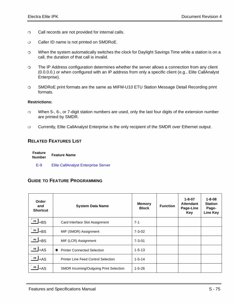
Electra Elite IPK Document Revision 4
Features and Specifications Manual S - 75
___________________________________________________________________________________
___________________________________________________________________________________
Call records are not provided for internal calls.
Caller ID name is not printed on SMDRoE.
When the system automatically switches the clock for Daylight Savings Time while a station is on a call, the duration of that call is invalid.
The IP Address configuration determines whether the server allows a connection from any client (0.0.0.0.) or when configured with an IP address from only a specific client (e.g., Elite CallAnalyst Enterprise).
SMDRoE print formats are the same as MIFM-U10 ETU Station Message Detail Recording print formats.
Restrictions:
When 5-, 6-, or 7-digit station numbers are used, only the last four digits of the extension number are printed by SMDR.
Currently, Elite CallAnalyst Enterprise is the only recipient of the SMDR over Ethernet output.
RELATED FEATURES LIST
GUIDE TO FEATURE PROGRAMMING
Feature Number
Feature Name
E-9 Elite CallAnalyst Enterprise Server
Orderand
ShortcutSystem Data Name
Memory Block
Function
1-8-07AttendantPage-Line
Key
1-8-08StationPage-
Line Key
+BS Card Interface Slot Assignment 7-1
+BS MIF (SMDR) Assignment 7-3-02
+BS MIF (LCR) Assignment 7-3-01
+AS Printer Connected Selection 1-5-13
+AS Printer Line Feed Control Selection 1-5-14
+AS SMDR Incoming/Outgoing Print Selection 1-5-26

S - 76 Station Message Detail Recording (SMDR)
___________________________________________________________________________________
___________________________________________________________________________________Document Revision 4 Electra Elite IPK
+AS SMDR Valid Call Time Assignment 1-5-25
+AS SMDR Print Format 1-5-02
+CSS COM Port Baud Rate Setting Assignment 1-8-35
+BM Start Time Selection 1-1-05
+AS SMDR Telephone Print Selection 4-56
+AC Station to Timer Class of Service 4-71
When the system is at default this Memory Block must be programmed for the feature to be used.
Orderand
ShortcutSystem Data Name
Memory Block
Function
1-8-07AttendantPage-Line
Key
1-8-08StationPage-
Line Key

Features and Specifications Manual S - 77
___________________________________________________________________________________
___________________________________________________________________________________
Station Name Assignment – User
Programmable S-18
FEATURE DESCRIPTION
This feature allows a user to program the Station Name for telephone extensions and allows the Attendant Station to program any extension in the system. The name is displayed on the Multiline Terminal LCD when an intercom or K-CCIS call is placed.
ENHANCEMENT(S)
Release 4000:
R4000 or higher is required to support 16 characters for the Station Name.
Release 3500:
R3500 or lower allows only six characters for the Station Name.
SYSTEM AVAILABILITY
Terminal Type:
All Stations
Required Components:
ESI(8)-U( ) ETUESIB/ESIE(8)-U( ) ETUSLI(8)/(4)-U( ) ETUOPX(2)-U( ) ETUVMP(2)/(4)/(8)/(16)-U( ) ETUCTP( ) ETUCTI( ) ETU
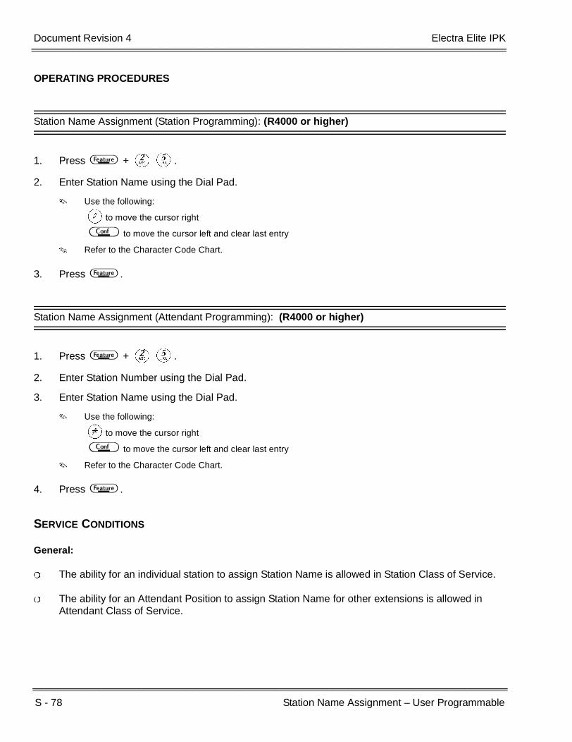
S - 78 Station Name Assignment – User Programmable
___________________________________________________________________________________
___________________________________________________________________________________Document Revision 4 Electra Elite IPK
OPERATING PROCEDURES
Station Name Assignment (Station Programming): (R4000 or higher)
1. Press A + BE.
2. Enter Station Name using the Dial Pad.
Use the following:
Lto move the cursor right
D to move the cursor left and clear last entry
Refer to the Character Code Chart.
3. Press A .
Station Name Assignment (Attendant Programming): (R4000 or higher)
1. Press A + BE.
2. Enter Station Number using the Dial Pad.
3. Enter Station Name using the Dial Pad.
Use the following:
Lto move the cursor right
D to move the cursor left and clear last entry
Refer to the Character Code Chart.
4. Press A .
SERVICE CONDITIONS
General:
The ability for an individual station to assign Station Name is allowed in Station Class of Service.
The ability for an Attendant Position to assign Station Name for other extensions is allowed in Attendant Class of Service.

Electra Elite IPK Document Revision 4
Features and Specifications Manual S - 79
___________________________________________________________________________________
___________________________________________________________________________________
Restrictions:
When PC Programming a terminal in off-line mode, the Attendant or station cannot assign Station Names.
For Hold Recall or Transfer Recall, the station recalling displays only the first six characters of the Programmed Station Name.
When an Attendant or station user changes or assigns a Station Name, Memory Block 4-18 (Station Name Assignment) reflects the change.
Only the first 13 characters of a 16-character name are displayed when using the Caller I.D. Display feature in voice mail on a Station-to-Station Call.
With 4000 or higher, the Station Name is displayed on the second row of a Multiline Terminal LCD regardless of the length of the Station Name assigned.
RELATED FEATURES LIST
Feature Number
Feature Name
A-5 Alphanumeric Display
C-19 Class of Service

S - 80 Station Name Assignment – User Programmable
___________________________________________________________________________________
___________________________________________________________________________________Document Revision 4 Electra Elite IPK
CHARACTER CODE TABLE
Press 1 2 3 4 5 6 7 8 9 0 Redial
1st 1 A D G J M P T W 0
2nd @ B E H K N Q U X ! +
3rd [ C F I L O R V Y “ ,
4th a d g j m S t Z # -
5th ] b e h k n p u w $ .
6th ^ c f i l o q v x % /
7th 2 3 4 5 6 r 8 y & :
8th / To A To D To G To J To M s To T z ;
9th 7 9 ( <
10th | To P To W ) =
11th To 0 >
12th ?
13th To
14th To 1
D Clears one character to the left.
# Used to move cursor to the right.

Electra Elite IPK Document Revision 4
Features and Specifications Manual S - 81
___________________________________________________________________________________
___________________________________________________________________________________
GUIDE TO FEATURE PROGRAMMING
Orderand
ShortcutSystem Data Name
Memory Block
Function
1-8-07AttendantPage-Line
Key
1-8-08StationPage-
Line Key
+BTS Class of Service (Attendant) Feature Selection 1
1-8-073-3
+BTS Class of Service (Station) Feature Selection 2
1-8-087-3
+BTT Station Name Assignment 4-18
When the system is at default this Memory Block must be programmed for the feature to be used.

S - 82 Station Name Assignment – User Programmable
___________________________________________________________________________________
___________________________________________________________________________________Document Revision 4 Electra Elite IPK
THIS PAGE INTENTIONALLY LEFT BLANK
Features and Specifications Manual S - 83
___________________________________________________________________________________
___________________________________________________________________________________
Station Outgoing Lockout S-19
FEATURE DESCRIPTION
Station Outgoing Lockout allows a station user to restrict outgoing calls by assigning a personal password.
SYSTEM AVAILABILITY
Terminal Type:
All Stations
Required Components:
None
OPERATING PROCEDURES
To set:
1. Go off-hook, and wait for internal dial tone.
2. Dial Password set Access Code. (default: not assigned).
3. Dial the Password Code:
KKKKKKKKKK (default).
4. Receive confirmation tone, and hang up.
S - 84 Station Outgoing Lockout
___________________________________________________________________________________
___________________________________________________________________________________Document Revision 4 Electra Elite IPK
To cancel:
1. Go off-hook, and wait for internal dial tone.
2. Dial Password cancel Access Code (default: not assigned).
3. Dial the Password code:
KKKKKKKKKK (default).
4. Receive confirmation tone, and hang up.
To cancel Telephone Password and Default Password using the Attendant Position:
1. Go off-hook, and wait for internal dial tone.
2. Dial Password cancel Access Code from another station (default: not assigned).
3. Dial the station number.
4. Wait for confirmation tone, and hang up.
To change the Password:
1. Go off-hook, and wait for internal dial tone.
2. Dial Password change Access Code (default: not assigned).
3. Dial current Password.
4. Enter new Password.
5. Hang up.

Electra Elite IPK Document Revision 4
Features and Specifications Manual S - 85
___________________________________________________________________________________
___________________________________________________________________________________
SERVICE CONDITIONS
General:
Internal calls, Paging, and Feature Access are provided when a telephone is locked out.
The password can have 10 digits.
Reset password from Attendant and Password Change does not have a default Access Code.
Service tone is not provided when setting a new password that is less than 10 digits.
A terminal indication is not provided when Station Outgoing Lockout is set.
RELATED FEATURES LIST
GUIDE TO FEATURE PROGRAMMING
Feature Number
Feature Name
C-21 Code Restriction
Orderand
ShortcutSystem Data Name
Memory Block
Function
1-8-07AttendantPage-Line
Key
1-8-08StationPage-
Line Key
+BTS Class of Service (Attendant) Feature Selection 1 1-8-07 2-4
+BTS Class of Service (Station) Feature Selection 2 1-8-08 2-3
+BTT Station to Class of Service Feature Assignment 4-17
+BA Access Code (1-, 2-, or 3-Digit) Assignment 1-1-46/47/48
035 ~ 038
+AC Code Restriction Class Assignment when Lockout is Set
1-1-70
When the system is at default this Memory Block must be programmed for the feature to be used.
S - 86 Station Outgoing Lockout
___________________________________________________________________________________
___________________________________________________________________________________Document Revision 4 Electra Elite IPK
THIS PAGE INTENTIONALLY LEFT BLANK

Features and Specifications Manual S - 87
___________________________________________________________________________________
___________________________________________________________________________________
Station Relocation S-20
FEATURE DESCRIPTION
Station Relocation enables a station to be moved from one location to another without programming the station data again. The station features and extension number are the same after it is moved to the new location.
SYSTEM AVAILABILITY
Terminal Type:
All Stations
Required Components:
None
OPERATING PROCEDURES
To set and cancel the Terminal Exchange Mode (Attendant):
1. Press A .
2. Dial Access Code HD.
To exchange two terminals:
1. Press E .
2. Dial the Station Relocation Access Code (default: not assigned).
3. Dial the extension number of the distant Multiline Terminal (i.e., the new Multiline Terminal).
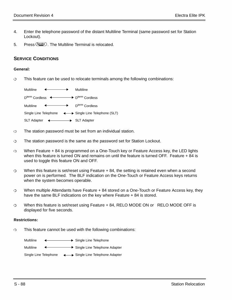
S - 88 Station Relocation
___________________________________________________________________________________
___________________________________________________________________________________Document Revision 4 Electra Elite IPK
4. Enter the telephone password of the distant Multiline Terminal (same password set for Station Lockout).
5. Press E . The Multiline Terminal is relocated.
SERVICE CONDITIONS
General:
This feature can be used to relocate terminals among the following combinations:
The station password must be set from an individual station.
The station password is the same as the password set for Station Lockout.
When Feature + 84 is programmed on a One-Touch key or Feature Access key, the LED lights when this feature is turned ON and remains on until the feature is turned OFF. Feature + 84 is used to toggle this feature ON and OFF.
When this feature is set/reset using Feature + 84, the setting is retained even when a second power on is performed. The BLF indication on the One-Touch or Feature Access keys returns when the system becomes operable.
When multiple Attendants have Feature + 84 stored on a One-Touch or Feature Access key, they have the same BLF indications on the key where Feature + 84 is stored.
When this feature is set/reset using Feature + 84, RELO MODE ON or RELO MODE OFF is displayed for five seconds.
Restrictions:
This feature cannot be used with the following combinations:
Multiline Multiline
Dterm Cordless Dterm Cordless
Multiline Dterm Cordless
Single Line Telephone Single Line Telephone (SLT)
SLT Adapter SLT Adapter
Multiline Single Line Telephone
Multiline Single Line Telephone Adapter
Single Line Telephone Single Line Telephone Adapter

Electra Elite IPK Document Revision 4
Features and Specifications Manual S - 89
___________________________________________________________________________________
___________________________________________________________________________________
An error tone is received and ERROR is displayed in the LCD under the following conditions:
A station number that causes a prohibited combination is entered.
A station number that does not exist is entered.
The station number of the terminal being used to perform Station Relocation is entered.
A Pilot Number or CAR number is entered.
The wrong password is entered.
A station number of the terminal to be exchanged is entered and that station is not idle.
Station Relocation Mode is not set.
This feature cannot be used to relocate DSS Consoles because consoles are not assigned station numbers. When Station Relocation is performed for a station that has an associated DSS Console, the station is relocated but not the DSS Console.
GUIDE TO FEATURE PROGRAMMING
Orderand
ShortcutSystem Data Name
Memory Block
Function
1-8-07AttendantPage-Line
Key
1-8-08StationPage-
Line Key
+BTS Class of Service (Attendant) Feature Selection 1 1-8-07 3-1
+BTS Class of Service (Station) Feature Selection 2 1-8-08 5-3
+BTT Station to Class of Service Feature Assignment 4-17
+BA Access Code (1-, 2-, or 3-Digit) Assignment 1-1-46/47/48
148
When the system is at default this Memory Block must be programmed for the feature to be used.

S - 90 Station Relocation
___________________________________________________________________________________
___________________________________________________________________________________Document Revision 4 Electra Elite IPK
THIS PAGE INTENTIONALLY LEFT BLANK
Features and Specifications Manual S - 91
___________________________________________________________________________________
___________________________________________________________________________________
Station Transfer S-21
FEATURE DESCRIPTION
Station Transfer allows any station user in the system to transfer any call to any other station. Outside calls can be transferred to Multiline Terminals without the direct line appearance. To initiate Call Transfer, press the Transfer key on a Multiline Terminal or use the hookswitch on a Single Line Telephone. The transfer is completed by going on-hook on a Multiline Terminal or Single Line Telephone.
SYSTEM AVAILABILITY
Terminal Type:
All Stations
Required Components:
None
OPERATING PROCEDURES
Using a Multiline Terminal with a call in progress:
1. Press G . Receive internal dial tone. The call is placed on Non-Exclusive Hold.
2. Dial the station number where the call is to be transferred.
3. Hang up.
Using a Single Line Telephone with a call in progress:
1. Provide hookflash. The call is put on Exclusive Hold. Receive internal dial tone.
2. Dial the station number of the station where call is to be transferred.
S - 92 Station Transfer
___________________________________________________________________________________
___________________________________________________________________________________Document Revision 4 Electra Elite IPK
3. Hang up.
- OR -
When the party answers, announce the transfer.
4. Restore the handset (transfer is completed).
SERVICE CONDITIONS
General:
After transferring an answered call, the Multiline Terminal user can press the Conference key on the Multiline Terminal even after the Transfer key is pressed to enter a conference.
After transferring an answered call, the Single Line Telephone user can enter a conference by providing a second hookflash.
Use Memory Block 4-66 (MOH or Ring Back Tone Selection) to assign MOH or Ring Back Tone for the outside party when a trunk call is placed on hold by the Transfer key on a Dterm, or hook flash from a Single Line Telephone, or the Transfer or Hold keys at a PSII station.
Restrictions
A Trunk-to-Trunk transfer can be established by the following operation:
1. While talking to an outside party, press the Hold Key.
2. Access a second outside line, and dial the desired number.
3. Press Transfer Key to complete the Trunk-to-Trunk transfer.
When the second call is to be transferred to another station (Not Trunk-to-Trunk), the user should press the Hold Key at step 3, then dial the desired station, and press the Transfer Key to complete the transfer.
RELATED FEATURE LIST
Feature Number
Feature Name
A-15 Attendant Transfer
D-13 Direct Station Selection (DSS)
M-7 Music on Hold

Electra Elite IPK Document Revision 4
Features and Specifications Manual S - 93
___________________________________________________________________________________
___________________________________________________________________________________
GUIDE TO FEATURE PROGRAMMING
Orderand
ShortcutSystem Data Name
Memory Block
Function
1-8-07AttendantPage-Line
Key
1-8-08StationPage-
Line Key
+BTS System Transfer/Camp-On Selection 1-1-11
+BMSystem Transfer/Camp-On Recall Time Selection
1-1-12
+BCS CO Transfer Ring Pattern Selection 1-1-13
+BCS CO Transfer Ring Tone Selection 1-1-14
+BMAttendant Add-on Console Transfer/Camp-on Recall Time Selection
1-1-64
+BTS Class of Service (Station) Feature Selection 2 1-8-08 4-2
+BTT MOH or Ring Back Tone Selection 4-66
+AC Station to Timer Class of Service 4-71

S - 94 Station Transfer
___________________________________________________________________________________
___________________________________________________________________________________Document Revision 4 Electra Elite IPK
THIS PAGE INTENTIONALLY LEFT BLANK

Features and Specifications Manual S - 95
___________________________________________________________________________________
___________________________________________________________________________________
Step Call S-22
FEATURE DESCRIPTION
A caller that receives a call waiting tone during an internal call can dial 2 (default) to access the next higher station number in the same 10s group (e.g., 10~19, 20~29, or 110~119).
SYSTEM AVAILABILITY
Terminal Type:
All Stations
Required Components:
None
OPERATING PROCEDURES
After calling a station and receiving a call waiting tone:
1. DialB(set at default).
2. The next higher available station number is called.
After attempting to System Call Park call in a busy location and receiving busy tone (e.g., System Call Park locations 0 and 1 are busy, and an attempt is made to park in location 0):
1. DialA, and receive busy.
2. DialB; call is parked in park location 2.

S - 96 Step Call
___________________________________________________________________________________
___________________________________________________________________________________Document Revision 4 Electra Elite IPK
SERVICE CONDITIONS
General:
Step Call operation can be performed only while a call waiting tone is heard.
When a call is stepped to the next higher station number, the next available station number is accessed.
It may not be the next consecutively numbered station.
Step Call is provided in a 10s group (e.g., 100~109) of stations. When the highest station number in a 10s group is reached and is busy, the search continues with the lowest number in the group.
This feature is unaffected by tenant assignment.
When Station 109 is call forwarded to Station 121, Station 121 is busy, and a call is made to Station 109 which forwards to Station 121, a call waiting tone is received. When Step Call is used, the call skips to Station 122, when available.
When using the Step Call feature, the system skips stations that are busy.
GUIDE TO FEATURE PROGRAMMING
Orderand
ShortcutSystem Data Name
Memory Block
Function
1-8-07AttendantPage-Line
Key
1-8-08StationPage-
Line Key
+BA Intercom Feature Access Code Assignment 1-2-24 002

Features and Specifications Manual S - 97
___________________________________________________________________________________
___________________________________________________________________________________
Store and Repeat S-23
FEATURE DESCRIPTION
Store and Repeat allows a Multiline Terminal user talking on a CO/PBX line to store any telephone number in memory for later use.
SYSTEM AVAILABILITY
Terminal Type:
All Multiline Terminals
Required Components:
None
OPERATING PROCEDURES
To use this feature with a CO/PBX Call in progress at a Multiline Terminal):
1. Press A .
2. Dial G.
3. Dial the desired number to be stored in memory.
4. Press A .
5. Restore the handset or press E .
S - 98 Store and Repeat
___________________________________________________________________________________
___________________________________________________________________________________Document Revision 4 Electra Elite IPK
To repeat a stored number:
Multifunction (Dial Access):
1. Press B .
2. DialL.
Key Function:
1. Go off-hook on a CO/PBX line; receive outside dial tone.
2. Press B .
3. Dial L.
To repeat a stored number (R4000 or higher):
Multifunction (Dial Access):
1. Press B .
2. DialLL.
Key Function:
1. Go off-hook on a CO/PBX line; receive outside dial tone.
2. Press B .
3. Dial LL.
SERVICE CONDITIONS
General:
Store and Repeat and Save and Repeat cannot be used simultaneously from a Multiline Terminal. The same memory area is shared by both features.
The stored number is retained by the memory backup battery.
A new number can be saved over the last Store and Repeat number.
When entering a Store and Repeat number, the Conference key can be used to backspace and erase digits entered.

Electra Elite IPK Document Revision 4
Features and Specifications Manual S - 99
___________________________________________________________________________________
___________________________________________________________________________________
Press the Redial key to store pauses with a Store and Repeat number.
A hookflash cannot be saved in a Store and Repeat number.
A hookflash is sent to the CO/PBX line when you press the Recall key during Store and Repeat.
R4000 or higher requires that # # be used to repeat the stored number.
Restrictions:
Store and Repeat is valid only on outside line calls.
RELATED FEATURE LIST
Feature Number
Feature Name
S-1 Save and Repeat

S - 100 Store and Repeat
___________________________________________________________________________________
___________________________________________________________________________________Document Revision 4 Electra Elite IPK
THIS PAGE INTENTIONALLY LEFT BLANK
Features and Specifications Manual S - 101
___________________________________________________________________________________
___________________________________________________________________________________
Stored Hookflash S-24
FEATURE DESCRIPTION
Stored Hookflash allows any Multiline Terminal user to store a hookflash in a Speed Dial buffer to allow one-step access to certain Centrex or PBX features.
System Software permits input stored characters to be entered on the dial pad, but no longer allows the Character Code Table to be used.
SYSTEM AVAILABILITY
Terminal Type:
All Multiline Terminals
Required Components:
None
OPERATING PROCEDURES
To program a Hookflash in Feature Access key programmed for Speed Dial:
1. Press A .
2. Press B .
3. Press the Feature Access key.
4. Dial K.
5. Dial the Trunk or Trunk Group Access Code (maximum four digits).
6. Press C to enter a hookflash.
7. Dial the desired telephone number.
8. Press A .

S - 102 Stored Hookflash
___________________________________________________________________________________
___________________________________________________________________________________Document Revision 4 Electra Elite IPK
To program a Hookflash on a One-Touch key programmed for Speed Dial:
1. Press A .
2. Press B .
3. Press the One-Touch key.
4. Dial K.
5. Dial the Trunk or Trunk Group Access Code (maximum four digits).
6. Press C to enter a hookflash.
7. Dial the desired telephone number.
8. Press A .
To program a Hookflash in the System Speed Dial buffer (Attendant Position only):
1. Press A .
2. Press B .
3. Dial the System Speed Dial buffer number (KK~GI or KKK~ III).
4. Dial the Trunk or Trunk Group Access Code (maximum four digits).
5. Press C to enter a hookflash.
6. Dial the desired telephone number.
7. Press H , and enter name using the Character Code Table.
- OR -
Use the dial pad to enter the name.
Refer to S-12 Speed Dial Stored Characters on page S-47.
8. Press A .
Electra Elite IPK Document Revision 4
Features and Specifications Manual S - 103
___________________________________________________________________________________
___________________________________________________________________________________
To use the Speed Dial buffer with Stored Hookflash using a Multiline Terminal:
Key Function:
1. Press the desired CO/PBX line key.
2. Press B .
3. Dial the Speed Dial buffer number (KK~GI or KKK~ III).
Multifunction (Dial Access):
1. Press B .
2. Dial the Speed Dial buffer number (KK~GI or KKK~ III).
To use Feature Access or a One-Touch key programmed for Station Speed Dial with Stored Hookflash at a Multiline Terminal:
Key Function:
1. Press the desired CO/PBX line key.
2. Press the desired Feature Access or One-Touch key.
Multifunction (Dial Access):
Press the desired Feature Access or One-Touch key.
SERVICE CONDITIONS
General:
This feature is available on all Multiline Terminals.
Stored Hookflash is effective on Loop Start and Ground Start trunks when the system is installed behind a PBX or Centrex system.
A hookflash can be stored in System and Station Speed Dial buffers.
The LCD display for a Stored Hookflash shows / during programming and use of the Speed Dial buffer.
A Stored Hookflash can be used with a stored number.
For example: A Station Speed Dial Key is stored as hookflash + 110. Press this particular keyduring an outside line conversation to automatically trigger a Centrex transfer.

S - 104 Stored Hookflash
___________________________________________________________________________________
___________________________________________________________________________________Document Revision 4 Electra Elite IPK
GUIDE TO FEATURE PROGRAMMING
Orderand
ShortcutSystem Data Name
Memory Block
Function
1-8-07AttendantPage-Line
Key
1-8-08StationPage-
Line Key
+BCM Hookflash Time Selection 1-1-02
+BCT Trunk Type Selection 3-91
Features and Specifications Manual S - 105
___________________________________________________________________________________
___________________________________________________________________________________
Synchronous Ringing S-25
FEATURE DESCRIPTION
Synchronous Ringing synchronizes CO/PBX incoming ringing with the incoming ringing pattern from a Central Office.
SYSTEM AVAILABILITY
Terminal Type:
All Stations except Single Line Telephones connected to AP(R)-R or APR-U Unit
Required Components:
None
OPERATING PROCEDURES
None
SERVICE CONDITIONS
Restrictions:
Synchronous Ringing is not supported for Tie/DID incoming calls, Off-Hook Ringing, or CO/PBX Ring Transfers.
RELATED FEATURES LIST
Feature Number
Feature Name
D-14 Distinctive Ringing

S - 106 Synchronous Ringing
___________________________________________________________________________________
___________________________________________________________________________________Document Revision 4 Electra Elite IPK
GUIDE TO FEATURE PROGRAMMING
Orderand
ShortcutSystem Data Name
Memory Block
Function
1-8-07AttendantPage-Line
Key
1-8-08StationPage-
Line Key
+BCS Synchronous Ringing Selection 1-1-59

Features and Specifications Manual S - 107
___________________________________________________________________________________
___________________________________________________________________________________
System Data Up/Down Load S-26
FEATURE DESCRIPTION
System Data Up/Down Load, included with NEC Electra Elite IPK System Administration Terminal (SAT) Software, transfers Station Speed Dial data, System Speed Dial data, and all System Data from/to an NEC PowerMate or Pentium1-compatible PC. System Data Up/Down Load can be performed locally or from a remote location.
SYSTEM AVAILABILITY
Terminal Type:
Not applicable
Required Components:
Local Access:
External Modem
MIFM-U10 ETU
3.5"/5.25” floppy disk with SAT PC programming software
Straight DB-9 cable
Null modem adaptor cable (required for a direct connection between MIFM-U( ) ETU and a modem)
Internal Modem
MIFM-U10 ETU with Modem Kit Unit (to install on the MIFM-U10 ETU)
- OR -
MIFM-U20 ETU with MOD-U10 Unit (to install on the MIFM-U20 ETU)
- OR -
SPE(M)-U( ) with Modem to install on the SPE(M)-U( ) ETU.
1. Pentium is a registered trademark of Intel Corporation.

S - 108 System Data Up/Down Load
___________________________________________________________________________________
___________________________________________________________________________________Document Revision 4 Electra Elite IPK
Remote Access:
An MIF-Modem Unit local with an MNP Class 5 modem at the remote site
MNP1 Class 5 compatible modem at both sites
Pentium PC running Windows 95/98
OPERATING PROCEDURE
To up/down load system data:
1. Access the MIFM-U( ) ETU via a direct connection from a compatible PC, or use an MPN Class 5 compatible modem from a remote location through an outside line.
2. Select menu for Up/Down Load (communication menu).
3. Select the item (e.g., Speed Dial) to be transferred.
SERVICE CONDITIONS
General:
This feature allows System Data to be programmed from a PC connected to the system.
Data that can be transferred includes:
Complete System Data
Partial System Data
All System Data Blocks
Tenant Blocks (All/Tenant/Individual Tenant)
Trunk Blocks (All Trunk/Individual Trunk)
Terminal Blocks (All Terminal/Individual Terminal)
Trunk Route Blocks
System Speed Dial
1. MNP is a registered trademark of Microcom, Inc.

Electra Elite IPK Document Revision 4
Features and Specifications Manual S - 109
___________________________________________________________________________________
___________________________________________________________________________________
Station Speed Dial
All Station Speed Dial
Block Station Speed Dial
Individual Station Speed Dial
One-Touch DSS Speed Dial
Loading Time (all data)
The user should verify the system hardware configuration between the System Program Technician Software and the system or download the complete assignment mode before up/down loading System Data.
GUIDE TO FEATURE PROGRAMMING
OperationOn-Site
(9600 bps)Remote Site(2400 bps)
UP LOAD 3~5 minute 5~10 minute
DOWN LOAD 3~5 minute 5~10 minute
Orderand
ShortcutSystem Data Name
Memory Block
Function
1-8-07AttendantPage-Line
Key
1-8-08StationPage-
Line Key
+BS Card interface Slot Assignment 7-1
S - 110 System Data Up/Down Load
___________________________________________________________________________________
___________________________________________________________________________________Document Revision 4 Electra Elite IPK
THIS PAGE INTENTIONALLY LEFT BLANK

Features and Specifications Manual T - 1
___________________________________________________________________________________
___________________________________________________________________________________
T1 Connection T-1
FEATURE DESCRIPTION
T1 Connection allows the system to be connected directly to FT1 carrier links using a public or private network. The Digital Trunk Interface, DTI-U( ) ETU, provides different types of trunk signaling with FT1 carrier links using System Programming. The DTI-U( ) ETU supports Loop Start/Ground Start and Tie line/DID trunks.
SYSTEM AVAILABILITY
Terminal Type:
All Stations
Required Components:
DTI-U( ) ETU
Phase Lock Oscillator, CLKG-U( ) Unit: Piggybacked on the CPUI( )-U( ) ETU for the Electra Elite IPK for network synchronization
Locally provided Channel Service Unit (CSU) installed
OPERATING PROCEDURES
Normal call handling procedures apply.
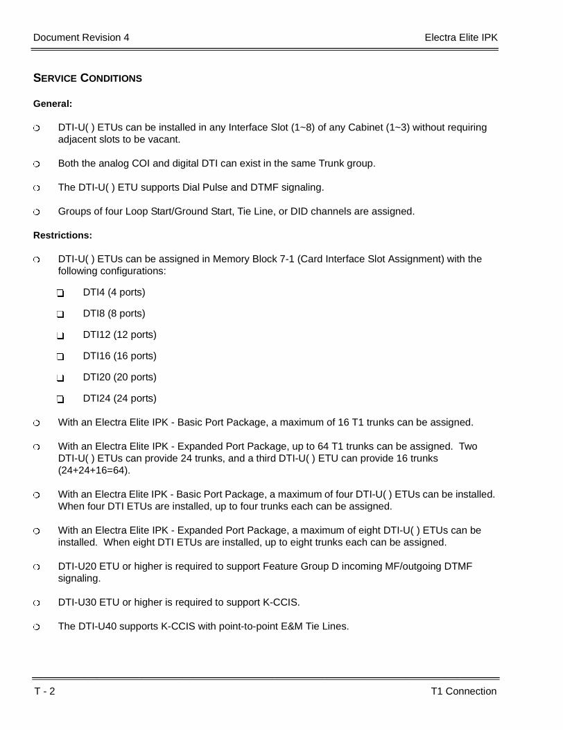
T - 2 T1 Connection
___________________________________________________________________________________
___________________________________________________________________________________Document Revision 4 Electra Elite IPK
SERVICE CONDITIONS
General:
DTI-U( ) ETUs can be installed in any Interface Slot (1~8) of any Cabinet (1~3) without requiring adjacent slots to be vacant.
Both the analog COI and digital DTI can exist in the same Trunk group.
The DTI-U( ) ETU supports Dial Pulse and DTMF signaling.
Groups of four Loop Start/Ground Start, Tie Line, or DID channels are assigned.
Restrictions:
DTI-U( ) ETUs can be assigned in Memory Block 7-1 (Card Interface Slot Assignment) with the following configurations:
DTI4 (4 ports)
DTI8 (8 ports)
DTI12 (12 ports)
DTI16 (16 ports)
DTI20 (20 ports)
DTI24 (24 ports)
With an Electra Elite IPK - Basic Port Package, a maximum of 16 T1 trunks can be assigned.
With an Electra Elite IPK - Expanded Port Package, up to 64 T1 trunks can be assigned. Two DTI-U( ) ETUs can provide 24 trunks, and a third DTI-U( ) ETU can provide 16 trunks (24+24+16=64).
With an Electra Elite IPK - Basic Port Package, a maximum of four DTI-U( ) ETUs can be installed. When four DTI ETUs are installed, up to four trunks each can be assigned.
With an Electra Elite IPK - Expanded Port Package, a maximum of eight DTI-U( ) ETUs can be installed. When eight DTI ETUs are installed, up to eight trunks each can be assigned.
DTI-U20 ETU or higher is required to support Feature Group D incoming MF/outgoing DTMF signaling.
DTI-U30 ETU or higher is required to support K-CCIS.
The DTI-U40 supports K-CCIS with point-to-point E&M Tie Lines.

Electra Elite IPK Document Revision 4
Features and Specifications Manual T - 3
___________________________________________________________________________________
___________________________________________________________________________________
DTI-U( ) ETUs cannot be upgraded to a higher version.Example:
A DTI-U10 ETU cannot be upgraded to a DTI-U20/30/40 ETU.
A DTI-U20 ETU cannot be upgraded to a DTI-U30/40 ETU.
A DTI-U30 ETU cannot be upgraded to a DTI-U40 ETU.
RELATED FEATURE LIST
Feature Number
Feature Name
A-23 Automatic Number Indication (ANI) on T1
C-5 Caller ID Indication (Analog Trunks)
D-9 Direct Inward Dialing (DID)
E-6 E&M Tie Lines (4-Wire)
I-9 ISDN-BRI Trunk Connections
I-10 ISDN-PRI Trunk Connections
K-1 Key-Common Channel Interoffice Signaling (K-CCIS)
M-6 Multiple Trunk Groups
T-2 Tandem Switching of 4-Wire E&M Tie Lines
U-5 Universal Slots
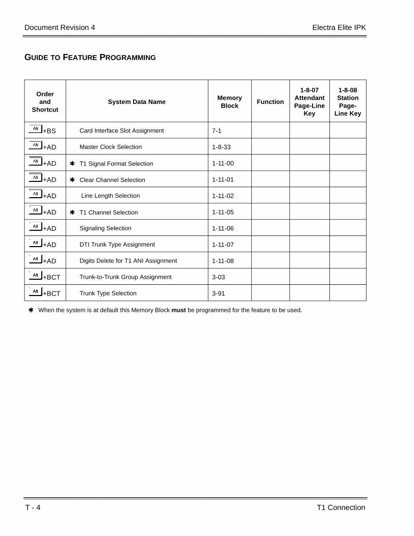
T - 4 T1 Connection
___________________________________________________________________________________
___________________________________________________________________________________Document Revision 4 Electra Elite IPK
GUIDE TO FEATURE PROGRAMMING
Orderand
ShortcutSystem Data Name
Memory Block
Function
1-8-07AttendantPage-Line
Key
1-8-08StationPage-
Line Key
+BS Card Interface Slot Assignment 7-1
+AD Master Clock Selection 1-8-33
+AD T1 Signal Format Selection 1-11-00
+AD Clear Channel Selection 1-11-01
+AD Line Length Selection 1-11-02
+AD T1 Channel Selection 1-11-05
+AD Signaling Selection 1-11-06
+AD DTI Trunk Type Assignment 1-11-07
+AD Digits Delete for T1 ANI Assignment 1-11-08
+BCT Trunk-to-Trunk Group Assignment 3-03
+BCT Trunk Type Selection 3-91
When the system is at default this Memory Block must be programmed for the feature to be used.

Features and Specifications Manual T - 5
___________________________________________________________________________________
___________________________________________________________________________________
Tandem Switching of 4-Wire E&M Tie Lines T-2
FEATURE DESCRIPTION
Tandem Switching of 4-wire E&M Tie Lines allows connecting E&M Tie Lines to other trunks through the system without help or supervision from an internal station to allow distant-end system users to remotely access trunks. Pad control is provided on the TLI(2)-U( ) ETU by a programmable transmission pad to adjust to the line loss levels of the Tie line accessed.
SYSTEM AVAILABILITY
Terminal Type:
All Stations
Required Components:
TLI(2)-U( ) ETU or DTI-U( ) ETU
OPERATING PROCEDURES
To use this feature:
Select an E&M Tie Line and dial a station number or Trunk Group Access Code and telephone number in the distant-end system.
- OR -
The distant-end system user can select an E&M Tie line (from the local system) and dial the applicable Trunk Access Code and the desired number or extension number in the local system.

T - 6 Tandem Switching of 4-Wire E&M Tie Lines
___________________________________________________________________________________
___________________________________________________________________________________Document Revision 4 Electra Elite IPK
SERVICE CONDITIONS
General:
The Expanded Port Package handles 32 simultaneous tandem calls.
The Basic Port Package handles 8 simultaneous tandem calls.
After a tandem connection is complete, the trunks return to idle if either party hangs up, and a disconnect signal is received or the Disconnect Time (default: 60 minutes) set in Memory Block 1-4-00 (Tandem Transfer Automatic Disconnect Time Selection) elapses.
Tandem Switching of E&M Tie Lines can be accomplished through several Electra Elite IPK systems.
The local Electra Elite IPK system can be programmed to restrict individual station users access to specific E&M Tie Lines. Each station can be programmed to restrict the maximum number of digits dialed on an E&M Tie Line by assigning Code Restriction.
Access to outside lines by an E&M Tie Line user is recorded by SMDR where the CO line is connected. The originating system may also record the Tie Line user using its own SMDR.
Tandem connection can be allowed/denied per Trunk group for one or both directions. Assigned Tie/DID lines can add/delete up to two digits per Trunk group.
The TLI(2)-U( ) ETU has Internal or External Software pad control.
Internal Software pad control is applied during E&M Tie line (transmit and receive) connections.
External Software pad control applies to the following connections:
E&M Tie Line to CO Trunk
E&M Tie Line to E&M Tie Line
CO Trunk to E&M Tie Line
Restrictions:
Tandem connection is not monitored for Code Restriction or LCR.

Electra Elite IPK Document Revision 4
Features and Specifications Manual T - 7
___________________________________________________________________________________
___________________________________________________________________________________
RELATED FEATURES LIST
GUIDE TO FEATURE PROGRAMMING
Feature Number
Feature Name
E-6 E&M Tie Lines (4-Wire)
U-4 Uniform Numbering Network
Orderand
ShortcutSystem Data Name
Memory Block
Function
1-8-07AttendantPage-Line
Key
1-8-08StationPage-
Line Key
+BS Card Interface Slot Assignment 7-1
+ALNTie Line Networking Tandem Connection Assignment
5-01
+BCT Trunk Internal Transmit Pad Selection 3-29
+BCT Trunk Internal Receive Pad Selection 3-30
+BCT Trunk External Transmit Pad Selection 3-31
+BCT Trunk External Receive Pad Selection 3-32
+ATTandem Transfer Automatic Disconnect Time Selection
1-4-00

T - 8 Tandem Switching of 4-Wire E&M Tie Lines
___________________________________________________________________________________
___________________________________________________________________________________Document Revision 4 Electra Elite IPK
THIS PAGE INTENTIONALLY LEFT BLANK
Features and Specifications Manual T - 9
___________________________________________________________________________________
___________________________________________________________________________________
Tenant Service T-3
FEATURE DESCRIPTION
Tenant Service subdivides the system into a maximum of 48 Tenants that have outside line access.
SYSTEM AVAILABILITY
Terminal Type:
Not applicable
Required Components:
None
OPERATING PROCEDURES
None
SERVICE CONDITIONS
General:
Multiple tenants can share outgoing lines.
Outgoing calls and Add-On Conferences may be accessed between tenants.
Internal calls may be made to different tenants.
Tenant assignment applies to Multiline Terminals and Single Line Telephones.
To pick up a call in another tenant, a Call Pickup – Other Tenant Access Code must be used.
Day/Night Mode Switching can be set per tenant; however, Automatic Day/Night Mode Switching can only be set system-wide.
System Speed Dial display indication on the LCD of a Multiline Terminal is assigned per tenant.
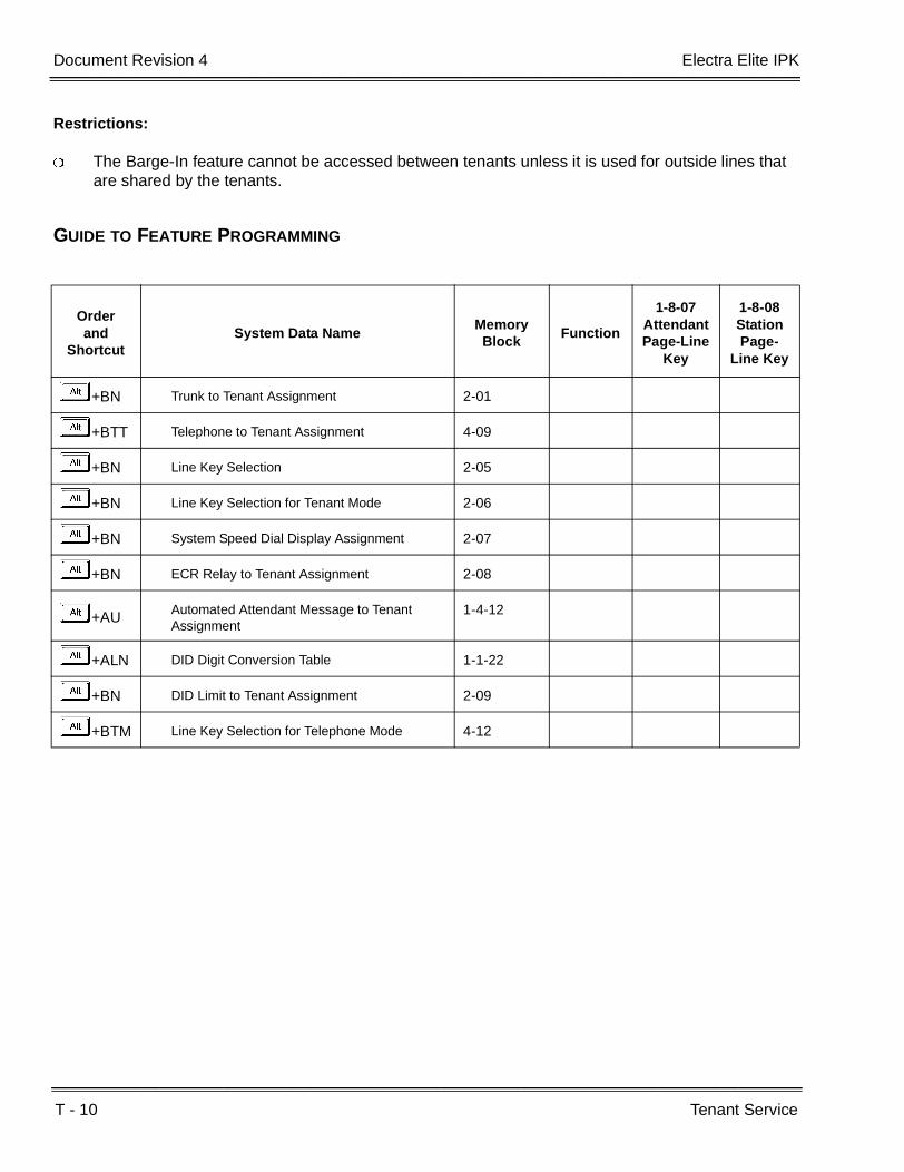
T - 10 Tenant Service
___________________________________________________________________________________
___________________________________________________________________________________Document Revision 4 Electra Elite IPK
Restrictions:
The Barge-In feature cannot be accessed between tenants unless it is used for outside lines that are shared by the tenants.
GUIDE TO FEATURE PROGRAMMING
Orderand
ShortcutSystem Data Name
Memory Block
Function
1-8-07AttendantPage-Line
Key
1-8-08StationPage-
Line Key
+BN Trunk to Tenant Assignment 2-01
+BTT Telephone to Tenant Assignment 4-09
+BN Line Key Selection 2-05
+BN Line Key Selection for Tenant Mode 2-06
+BN System Speed Dial Display Assignment 2-07
+BN ECR Relay to Tenant Assignment 2-08
+AU Automated Attendant Message to Tenant Assignment
1-4-12
+ALN DID Digit Conversion Table 1-1-22
+BN DID Limit to Tenant Assignment 2-09
+BTM Line Key Selection for Telephone Mode 4-12

Features and Specifications Manual T - 11
___________________________________________________________________________________
___________________________________________________________________________________
Three-Minute Reminder T-4
FEATURE DESCRIPTION
The Three-Minute Reminder tone is heard every three minutes by the Multiline Terminal user who originated or answered an outside call.
SYSTEM AVAILABILITY
Terminal Type:
All Multiline Terminals
Required Components:
None
OPERATING PROCEDURES
None
SERVICE CONDITIONS
General:
The Three-Minute Reminder produces a tone every three minutes from the built-in speaker on the Multiline Terminal during incoming or outgoing trunk calls.
The time starts counting when the Elapsed Call Time begins. The time begins immediately when an incoming call is answered.
The Three-Minute Reminder is provided for Add-On Conference calls.
The Three-Minute Reminder feature is not available for Single Line Telephones or for handsfree mode on a Multiline Terminal.

T - 12 Three-Minute Reminder
___________________________________________________________________________________
___________________________________________________________________________________Document Revision 4 Electra Elite IPK
GUIDE TO FEATURE PROGRAMMING
Orderand
ShortcutSystem Data Name
Memory Block
Function
1-8-07AttendantPage-Line
Key
1-8-08StationPage-
Line Key
+BTM 3-Minute Alarm Selection 4-94
When the system is at default this Memory Block must be programmed for the feature to be used.

Features and Specifications Manual T - 13
___________________________________________________________________________________
___________________________________________________________________________________
Tone Override T-5
FEATURE DESCRIPTION
The Multiline Terminal user that calls a busy station and receives a call waiting tone can generate a Tone Override that is heard by the originator and busy station. The busy station user can place the existing call on hold to answer the Override.
SYSTEM AVAILABILITY
Terminal Type:
All Multiline Terminals
Required Components:
None
OPERATING PROCEDURES
After calling a station and receiving call waiting tone:
1. Dial Access CodeJ (as set at default) to send the Tone Override.
2. Wait for confirmation tone.
3. Wait for the receiving party to answer the Tone Override, and then talk with party.
To answer Tone Override:
1. Receive Tone Override.
2. Press H , and talk with the party.

T - 14 Tone Override
___________________________________________________________________________________
___________________________________________________________________________________Document Revision 4 Electra Elite IPK
SERVICE CONDITIONS
General:
One Tone Override at a time can be received at a Multiline Terminal. This Tone Override is heard over the handset and speaker (when the receiving party is off-hook with the handset).
When a Multiline Terminal is assigned for Data Line Security, a Tone Override is not heard over the handset; however, the Tone Override is sent and heard from the speaker when the Multiline Terminal user is off-hook with the handset.
Restrictions:
Tone Override can be accomplished only after receiving a call waiting tone.
Tone Override may be denied for the following reasons:
The Multiline Terminal is set in the Do Not Disturb (DND) mode.
Auto Redial is activated.
Station Programming is activated.
The Multiline Terminal is denied Tone Override.
Another station is already sending a Tone Override to this station.
Account Code Entry is activated.
When Tone Override is used from a Dial Pulse Single Line Telephone, default Access Code must be changed to a numerical digit.
Tone Override is allowed only from a Single Line Telephone until the PBR times out (default: 10 seconds).
GUIDE TO FEATURE PROGRAMMING
Orderand
ShortcutSystem Data Name
Memory Block
Function
1-8-07AttendantPage-Line
Key
1-8-08StationPage-
Line Key
+BTS Class of Service (Station) Feature Selection 2 1-8-08 1-8, 3-3
+BTTStation to Class of Service Feature Assignment
4-17
+BTT SLT Data Line Security Assignment 4-90

Features and Specifications Manual T - 15
___________________________________________________________________________________
___________________________________________________________________________________
Trunk Queuing T-6
FEATURE DESCRIPTION
Trunk Queuing increases call processing efficiency. When all outside lines or a selected line are busy, the telephone user can queue on the busy line. When a line becomes available, the system provides an internal incoming ring to the queuing station. When the line is no longer needed, the queue request can be canceled before the line becomes available by dialing an Access Code. Each station user can queue an outside line by selecting the specific trunk in the queue procedure. This feature allows a station user to set trunk queuing to the specified trunk, internal Trunk group, or Route Advance Block.
SYSTEM AVAILABILITY
Terminal Type:
All Stations
Required Components:
None
OPERATING PROCEDURES
Using a Multiline Telephone when all outside lines are busy:
1. Press the desired busy outside line key.
2. Wait for busy tone.
3. Dial the Trunk Queuing Access Code (default: GH).
4. Restore the handset.
- OR -
Dial the Access Code for outside line.
5. Wait for busy tone.

T - 16 Trunk Queuing
___________________________________________________________________________________
___________________________________________________________________________________Document Revision 4 Electra Elite IPK
6. Dial the Trunk Queuing Access Code (default: GH).
7. Restore the handset.
Using a Single Line Telephone when all outside lines are busy:
1. Dial the Access Code for outside line.
2. Wait for busy tone.
3. Dial the Trunk Queuing Access Code (default: GH).
4. Restore the handset.
Using a Multiline Terminal or a Single Line Telephone when an outside line becomes available:
1. Receive internal ringing tone.
2. Lift the handset or press E .
3. Wait for the outside dial tone.
4. Dial the desired number.
To cancel this feature using a Multiline Terminal or a Single Line Telephone:
1. Lift the handset or press E .
2. Wait for internal dial tone.
3. Dial the Trunk Queuing Cancel Access Code (default: GI).
4. Restore the handset.

Electra Elite IPK Document Revision 4
Features and Specifications Manual T - 17
___________________________________________________________________________________
___________________________________________________________________________________
SERVICE CONDITIONS
General:
A station that has Trunk Queuing set is notified by internal ringing tone when the station is idle, and the queued outside line becomes free. Multiline Terminals with an LCD display the message LINE IDLE when the outside line becomes free. The Multiline Terminal user goes off-hook to receive outside line dial tone.
Incoming ringing calls have priority over CO/PBX line queuing.
When two or more stations are queued to the same outside line, Trunk Group, or Route Advance Block, a ringing tone is sent to the Multiline Terminals in the order set, indicating that the queued outside line is now free.
When a station user that has set Trunk Queuing sets another queue, the original Trunk Queue is canceled.
When a station with a CO/PBX queue set is busy on a different call when the queued line becomes available, the outside line can be seized by another station. Trunk Queuing is still set until both the trunk and station are idle at the same time.
The station user that set an outside line queue can dial an Access Code to cancel it.
When the station user places an outside call using LCR, Trunk Queuing cannot be set.
Restrictions:
Trunk Queuing cannot be set on an outgoing restricted line. When tried, reorder tone is provided.
GUIDE TO FEATURE PROGRAMMING
Orderand
ShortcutSystem Data Name
Memory Block
Function
1-8-07AttendantPage-Line
Key
1-8-08StationPage-
Line Key
+BTS Class of Service (Station) Feature Selection 2 1-8-08 1-2
+BTTStation to Class of Service Feature Assignment
4-17
+BT Trunk Queuing Timeout Selection 1-1-37

T - 18 Trunk Queuing
___________________________________________________________________________________
___________________________________________________________________________________Document Revision 4 Electra Elite IPK
THIS PAGE INTENTIONALLY LEFT BLANK
Features and Specifications Manual T - 19
___________________________________________________________________________________
___________________________________________________________________________________
Trunk-to-Trunk Transfer T-7
FEATURE DESCRIPTION
Trunk-to-Trunk Transfer allows any station user to establish Trunk-to-Trunk Transfers between two CO/PBX (when disconnect signal is provided), DID, and/or E&M Tie line calls.
ENHANCEMENT(S)
Release 2000:
With R2000 or higher, a user of a Single Line Telephone or PSII can perform a Trunk-to-Trunk Transfer.
SYSTEM AVAILABILITY
Terminal Type:
All Stations except Single Line Telephones connected to the AP(A)-R/AP(R)-R Unit or the APA-U/APR-U Unit
Required Components:
None
OPERATING PROCEDURES
Using Multiline Terminal with an outside call in progress:
1. Press G , and wait for internal dial tone.
2. Dial the Trunk Access Code (either CO/PBX line, DID, or E&M Tie line) for desired trunk.
3. Dial the desired number.
4. Press G to establish a Trunk-to-Trunk connection.
5. Hang up.

T - 20 Trunk-to-Trunk Transfer
___________________________________________________________________________________
___________________________________________________________________________________Document Revision 4 Electra Elite IPK
Using a Single Line Telephone with an outside call in progress (R2000 or higher):
1. Provide hookflash. The call is placed on Exclusive Hold. Receive internal dial tone.
2. Dial the Trunk Access Code for applicable trunk.
3. Dial the applicable number.
4. Hang up.
To establish a Trunk-to-Trunk transfer:
1. While talking to an outside party, press H .
2. Access a second outside line, and dial the desired number.
3. Press G to complete the Trunk-to-Trunk transfer.
When the second call is to be transferred to another station (not Trunk-to-Trunk), the user should press H at step 3, dial the desired station, and press G to complete the transfer.
SERVICE CONDITIONS
General:
All lines used for Trunk-to-Trunk Transfers must provide remote disconnect supervision.
A conference circuit is not required for Trunk-to-Trunk Transfer.
A Station user cannot reenter Trunk-to-Trunk Transfer after the connection is established.
After Trunk-to-Trunk Transfer is established, both trunks are released when a disconnect signal is received by either trunk or when the Automatic Disconnect Time runs out.
When Trunk-to-Trunk Transfer is established using Call Appearance keys, the CAP keys are released and are available for other calls.
Restrictions:
A Single Line Telephone cannot perform a Trunk-to-Trunk Transfer (R1700 or lower only).
A Single Line Telephone connected to an AP(A)-R/AP(R)-R Unit or APA-U/APR-U Unit cannot perform a Trunk-to-Trunk Transfer.

Electra Elite IPK Document Revision 4
Features and Specifications Manual T - 21
___________________________________________________________________________________
___________________________________________________________________________________
RELATED FEATURES LIST
GUIDE TO PROGRAMMING
Feature Number
Feature Name
A-15 Attendant Transfer
A-27 Automatic Trunk-to-Trunk Transfer
S-21 Station Transfer
Orderand
ShortcutSystem Data Name
Memory Block
Function
1-8-07AttendantPage-Line
Key
1-8-08StationPage-
Line Key
+BCT Trunk-to-Trunk Transfer Yes/No Selection 3-04
+BTS Class of Service (Station) Feature Selection 2 1-8-08 3-5
+BTT Station to Class of Service Feature Assignment
4-17
+ATTandem Transfer Automatic Disconnect Time Selection
1-4-00
When the system is at default this Memory Block must be programmed for the feature to be used.
T - 22 Trunk-to-Trunk Transfer
___________________________________________________________________________________
___________________________________________________________________________________Document Revision 4 Electra Elite IPK
THIS PAGE INTENTIONALLY LEFT BLANK
Features and Specifications Manual T - 23
___________________________________________________________________________________
___________________________________________________________________________________
Two-Color LEDs T-8
FEATURE DESCRIPTION
Multiline Terminals have Two-Color (green or red) LEDs for Flexible Line keys and the Large LED indications. The color indicates station status (red) or message status (green). Green indicates I-Hold (Exclusive and Non-Exclusive), I-Use, and recall conditions. Other functions are indicated with a red LED. The Attendant Add-On Console is also provided with 2-color (green or red) LEDs for direct access to stations.
SYSTEM AVAILABILITY
Terminal Type:
All Multiline Terminals and Attendant Add-On Consoles
Required Components:
None
OPERATING PROCEDURES
None
SERVICE CONDITIONS
Multiline Terminal Flexible Line keys and Large LEDs are 2-color (red or green) LEDs.
Each of the 48 DSS keys on the Attendant Add-On Console has two individual LEDs (one red and one green). The remaining 12 Function keys have one red LED.
Each Feature, Conf, Speaker, and Answer key on every Multiline Terminal has a red LED.
Refer to the Hardware Specifications chapter in the Electra Elite IPK General Description Manual for more information.

T - 24 Two-Color LEDs
___________________________________________________________________________________
___________________________________________________________________________________Document Revision 4 Electra Elite IPK
THIS PAGE INTENTIONALLY LEFT BLANK

Features and Specifications Manual U - 1
___________________________________________________________________________________
___________________________________________________________________________________
Unified Messaging U-1
FEATURE DESCRIPTION
The EliteMail CTI Voice Processing systems, using the Electra Elite IPK system and a Local Area Network, provide Unified Messaging services for voice, fax and e-mail messages with access at either the desktop PC or the telephone. Unified Messaging lets the PC control telephone calls and information about each inbound and outbound call. This system includes the basic EliteMail CTI TeLANophy® Module.
Basic EliteMail CTI TeLANophy Module Features
ViewMail® with Live Record Module
All voice and fax messages are visible at a glance on the PC screen and can be sorted in any order. An intuitive Microsoft® Windows interface shows the sender name, subject, and the date and time messages were sent so the user can quickly prioritize them and respond immediately.
ViewCall® Plus
All inbound and outbound calls can be controlled from your PC. Outbound call control requires a TAPI adaptor on the user telephone. By managing calls on the PC instead of the telephone, ViewCall Plus lets you communicate more easily with people inside and outside the office. Three integrated windows are provided to control telephone calls, log all telephone activity, and manage data about each call. With a click of the mouse you can take a call, ask a caller to hold, route the call to another extension, or send the call to voice mail.
Optional EliteMail CTI TeLANophy Module Features
ViewFax™
This works in ViewMail to display faxes on screen and lets you send them to any printer. When a fax is received, a fax icon is displayed next to the message in ViewMail. Double click to open the message, and press the play button to listen to any voice annotation sent with the fax. Fax ports are built-in on the EliteMail CTI and are activated as a system option. Up to two Fax ports can be enabled on the EliteMail CTI.
Hospitality Package
The Hospitality package is used specifically by hotels and resorts to provide guests with personal, accurate, and timely messages. Features include personal greetings, security codes, guest directory, and wake up calls.

U - 2 Unified Messaging
___________________________________________________________________________________
___________________________________________________________________________________Document Revision 4 Electra Elite IPK
System Language Prompts
EliteMail CTI supports Dutch, UK English, Australian English, Portuguese, French, New Zealand English, Madrid and Mexican Spanish only, and French Canadian.
SYSTEM AVAILABILITY
Terminal Type:
All Multiline Terminals
Required Components:
EliteMail CTI(4)/(8)/(12)/(16) Port)
Desktop PC connected to the Local Area Network (LAN).
When using View Mail for Microsoft Messaging (VMM) with Office XP/2002 or Office 2000 you must have at least service pack 3 for Office installed prior to installing VMM. Failure to do so requires removing and installing the entire Office software suite again.
Microsoft Outlook (for Outlook 98 and Outlook 2000) needs Corporate or Workgroup version. When a customer is running the Windows XP operating system, the following versions of Microsoft Outlook will work with VMM:
Outlook 97
Outlook 98
Outlook 2000 with Service Pack 3
Outlook 2002 (XP) with Service Pack 3
Microsoft Windows Messaging
The release version of each TeLANophy application is:
ViewMail = 3.3.4
ViewMail for Microsoft Messaging (VMM) = 3.3.14
ViewCall Plus = 3.3.3
ViewFax = 3.0.4.1
These TeLANophy applications supersede all previous versions, are backwards compatible, and work on the following operating systems:
Windows XP
Window 98

Electra Elite IPK Document Revision 4
Features and Specifications Manual U - 3
___________________________________________________________________________________
___________________________________________________________________________________
Windows NT 4.0 with Service Pack 6a
Windows 2000
OPERATING PROCEDURES
None
SERVICE CONDITIONS
General:
When a call is transferred to a station that is call forwarded to Voice Mail, or the Quick transfer to Voice Mail feature is used, the call must be released (blind transferred) before Voice Mail answers the call. During the transfer, the transferring party hears ring back tone, and the external party hears Music on Hold (MOH) or ringback tone until the transfer is completed. MOH or ring back tone is determined by Memory Block 4-66 (MOH or Ring Back Tone Selection). This condition applies to the following software versions:
The EliteMail CTI can have an unlimited number of subscribers.
The TeLANophy license is included with the EliteMail CTI system and includes 50 seats of ViewMail and 50 seats of ViewCall Plus.
EliteMail CTI system allows at least 250 hours of storage.
A 19.2K modem is included for remote maintenance on the EliteMail CTI.
The EliteMail CTI has an AMD K6 300 and can be configured for 4, 8, 12, or 16 ports.
The operating system is OS/2 Warp 4.
An onboard Ethernet NIC card is included for connection to the LAN.
The Electra Elite IPK system can support up to 16 EliteMail CTI digital voice mail ports.
The EliteMail CTI provides Softkey integration for voice mail users.
The EliteMail CTI supports optional ActiveNet (AMIS only) and PlusNet.
Restrictions:
R1700 R2000 R2500 R3000 3500
R1.71 R2.01 R2.50 R3.00 R3.50
R2.02 R2.51 R3.01 R3.51
U - 4 Unified Messaging
___________________________________________________________________________________
___________________________________________________________________________________Document Revision 4 Electra Elite IPK
The EliteMail CTI with fax option is not a high volume fax server. Sites with high volume should use a dedicated fax server.
EliteMail CTI does not support the Fax on Demand (FOD) feature.
EliteMail CTI does not support tape backup hardware or procedures.
For Q941 or lower, the EliteMail CTI gathers Caller ID information only for Loop Start trunks directly inward terminated to the pilot of the CTI, and the user mailbox must be set to await answer transfer.
For Q941 or lower, the EliteMail CTI does not gather Caller ID information for Loop Start Caller ID trunks that forward to the pilot of voice mail nor ANI DID calls on T-1 or PRI trunks.
Starting with Q944 or higher, the EliteMail CTI gathers Caller ID name or number, but not both for any call with Caller ID information that leaves a message. This includes forwarded calls and messages left in mailboxes set for Release transfers. The information can be displayed only using ViewApps.
The EliteMail CTI performs Caller ID Call Return using ViewCall Plus only and only when the number is displayed.
When 5-, 6-, or 7-digit station numbers are used, this feature is not available.
COSESSION
Description
CoSession, a communication software tool available from NEC, is used for EliteMail to perform configuration, maintenance, and backup functions.
CoSession Client 7.0 is supported with the following operating systems.
Windows 9x
Windows NT 4.0
Windows 2000 / 2000 Pro
Windows XP Professional
Computer
The computer used as the CoSession client must be an x86-based PC desktop or notebook system meeting the minimum requirements for the chosen operating system.
Modem / Serial cable
An AT-command set modem is required for remote connections via modem. A Null-Modem cable is required for use in a Direct-Connection.
Electra Elite IPK Document Revision 4
Features and Specifications Manual U - 5
___________________________________________________________________________________
___________________________________________________________________________________
When using CoSession Direct Connect on Windows NT 4.0, Windows 2000, or Windows XP, COM ports can be initialized for use at up to 57,600 bps. Using those operating systems, COM ports cannot be initialized for use at 115,200 bps.
CoSession Direct Connect file transfer operations perform reliably up to 38,400 bps.
RELATED FEATURES LIST
Feature Number
Feature Name
Q-1 Quick Transfer to Voice Mail
S-16 Station Hunt
V-1 Voice Mail Integration (Analog)

U - 6 Unified Messaging
___________________________________________________________________________________
___________________________________________________________________________________Document Revision 4 Electra Elite IPK
THIS PAGE INTENTIONALLY LEFT BLANK
Features and Specifications Manual U - 7
___________________________________________________________________________________
___________________________________________________________________________________
Unified Messaging – EliteMail CTI-LX Lite U-2
FEATURE DESCRIPTION
The EliteMail CTI-LX Lite Voice Processing systems, using the Electra Elite IPK system and a Local Area Network, provide Unified Messaging services for voice and e-mail messages with access at either the desktop PC or the telephone. Unified Messaging lets the PC control telephone calls and information about each inbound and outbound call. This system includes the basic EliteMail TeLANophy® Module.
Basic EliteMail CTI TeLANophy Module Features
ViewMail® with Live Record Module
All voice and fax messages are visible at a glance on the PC screen and can be sorted in any order. An intuitive Microsoft® Windows interface shows the sender name, subject, and the date and time messages were sent so the user can quickly prioritize them and respond immediately.
ViewCall® Plus
All inbound and outbound calls can be controlled from your PC. Outbound call control requires a TAPI adaptor on the user telephone. By managing calls on the PC instead of the telephone, ViewCall Plus lets you communicate more easily with people inside and outside the office. Three integrated windows are provided to control telephone calls, log all telephone activity, and manage data about each call. With a click of the mouse you can take a call, ask a caller to hold, route the call to another extension, or send the call to voice mail.
Optional EliteMail CTI TeLANophy Module Features
Supported languages include Argentinian, Madrid, and Latin America Spanish; Australian English; Canadian French; Cantonese; Danish; Dutch, German, Hebrew; Italian; New Zealand English; Portuguese; Swedish; United Kingdom English; and United States English. The technician shall be able to reinstall available languages.
SYSTEM AVAILABILITY
Terminal Type:
All Multiline Terminals

U - 8 Unified Messaging – EliteMail CTI-LX Lite
___________________________________________________________________________________
___________________________________________________________________________________Document Revision 4 Electra Elite IPK
Required Components:
EliteMail VMP-U40 ETUEliteMail CTI-LX Lite Hard Drive KitDSP-U30 LX (for eight port installations)Desktop PC connected to the Local Area Network (LAN).
When using View Mail for Microsoft Messaging (VMM) with Office XP/2002 or Office 2000 you must have at least service pack 3 for Office installed prior to installing VMM. Failure to do so requires removing and installing the entire Office software suite again.
Microsoft Outlook, Outlook 2000, or Outlook 2002 needs Corporate or Workgroup version. When a customer is running the Windows XP operating system, the following versions of Microsoft Outlook will work with VMM:
Outlook 97
Outlook 98
Outlook 2000 with Service Pack 3
Outlook 2002 (XP) with Service Pack 3
Microsoft Windows Messaging
The release version of each TeLANophy application is:
ViewMail = 3.3.4
ViewMail for Microsoft Messaging (VMM) = 3.3.14
ViewCall Plus = 3.3.3
These TeLANophy applications supersede all previous versions, are backwards compatible, and work on the following operating systems:
Windows XP
Window 98
Windows NT 4.0 with Service Pack 6a
Windows 2000
OPERATING PROCEDURES
None

Electra Elite IPK Document Revision 4
Features and Specifications Manual U - 9
___________________________________________________________________________________
___________________________________________________________________________________
SERVICE CONDITIONS
General:
When a call is transferred to a station that is call forwarded to Voice Mail, or the Quick transfer to Voice Mail feature is used, the call must be released (blind transferred) before Voice Mail answers the call. During the transfer, the transferring party hears ring back tone, and the external party hears Music on Hold (MOH) or ringback tone until the transfer is completed. MOH or ring back tone is determined by Memory Block 4-66 (MOH or Ring Back Tone Selection). This condition applies to the following software versions:
A database from an existing OS/2-based EliteMail CTI product can be migrated to the Linux-based CTI-LX Lite.
The EliteMail CTI-LX Lite can have an unlimited number of subscribers.
The TeLANophy license is included with the EliteMail CTI-LX Lite system and includes five seats of ViewMail and five seats of ViewCall Plus.
Live record is supported through softkeys and ViewMail/VMM.
The EliteMail CTI-LX Lite system allows at least 1250 hours of storage.
A 28.6K modem is included for remote maintenance on the EliteMail CTI.
The EliteMail CTI-LX Lite includes Mailbox Manager, a utility that allows users to manage their mailboxes.
The EliteMail CTI-LX Lite can be configured for four or eight ports.
Normal fax line detection as in the DOS-based products can route fax calls to the Auto Attendant to one fixed fax machine.
The operating system is Linux Red Hat 7.2.
An onboard Ethernet NIC card is included for connection to the LAN.
The EliteMail CTI-LX Lite system can support up to 8 EliteMail CTI digital voice mail ports.
The EliteMail CTI provides Softkey integration for voice mail users.
R1700 R2000 R2500 R3000 3500
R1.71 R2.01 R2.50 R3.00 R3.50
R2.02 R2.51 R3.01 R3.51

U - 10 Unified Messaging – EliteMail CTI-LX Lite
___________________________________________________________________________________
___________________________________________________________________________________Document Revision 4 Electra Elite IPK
Restrictions:
A database from a DOS-based EliteMail CMS/FMS/VMP/VMS cannot be migrated to the Linux-based EliteMail CTI-LX Lite.
The EliteMail CTI-LX Lite does not support the View Fax feature or fax activation package.
The EliteMail CTI-LX Lite does not support tape backup hardware or procedures.
Live Monitor is supported only through ViewCall Plus, not by softkeys.
The EliteMail CTI-LX Lite displays Caller ID information using ViewMail, ViewMail for Microsoft Messaging (VMM), or ViewCall Plus and displays the name and/or number when provided by Telco. It cannot display Caller ID information using the telephone.
The EliteMail CTI-LX Lite performs Caller ID Call Return using ViewCall Plus only and only when the number is displayed.
When 5-, 6-, or 7-digit station numbers are used, this feature is not available.
The EliteMail CTI-LX Lite feature is not supported on U10, U20, or U30 hardware.
REMOTE MAINTENANCE
The EliteMail CTI-LX Lite does not support CoSession for maintenance. It uses an HTML browser (e.g., Internet Explorer). Refer to system documentation for more information.
The built-in modem can be used for remote web console and maintenance menu programming.
The web console interface can be used over the internet for remote programming; however, this requires the site IT Manager to allow access from the internet to the voice mail.
RELATED FEATURES LIST
Feature Number
Feature Name
Q-1 Quick Transfer to Voice Mail
S-16 Station Hunt
Features and Specifications Manual U - 11
___________________________________________________________________________________
___________________________________________________________________________________
Uniform Call Distribution (UCD) U-3
FEATURE DESCRIPTION
Uniform Call Distribution permits incoming DIT/ANA, DID/Tie, and CO ring transferred calls to terminate in a prearranged hunt group. Incoming calls are distributed based on longest idle time among all members of the UCD group. When an incoming DIT/ANA, DID call to a UCD group encounters all UCD stations busy or no-answer, the call is queued and the caller receives a Delay Announcement after a programmed time.
SYSTEM AVAILABILITY
Terminal Type:
All Stations
Required Components:
MIFA-U( ) ETU
OPERATING PROCEDURES
None
GENERAL DESCRIPTION
CALL PROCESSING
This section includes the following features:
Abandoned Call Search
Abandoned incoming calls are not connected to Agent positions. The system recognizes abandoned calls and removes them from queue on trunks that provide calling party disconnect supervision.
Call Distribution to Agents
Calls are automatically distributed among Agents in a UCD group based on longest idle time.

U - 12 Uniform Call Distribution (UCD)
___________________________________________________________________________________
___________________________________________________________________________________Document Revision 4 Electra Elite IPK
Call Transfer to UCD Group Queue
CO Trunk calls, that have terminated to either a normal station or a UCD Agent, can be transferred to a UCD group queue.
Night Service
When the UCD group is placed in Night Mode, the system can route all incoming UCD calls to Internal Station Number, Night Announcement, transfer to the Attendant, or Trunk-to-Trunk Transfer.
Overflow
Overflow allows calls, holding in queue for more than a programmed time, to be directed to an assigned station or Station Hunting group.
Queuing
All incoming calls destined for UCD groups are placed in queue when no Agent in the UCD group can handle the call. Queue is used to provide service in order of arrival (first in, first out).
Pilot Numbers
Pilot Numbers are programmed in the System Data according to the numbering plan assigned for the system. Pilot Numbers do not correspond to any line appearances, either physical or virtual, in the Electra Elite IPK system. No hardware equipment is required to assign a Pilot number. A UCD Group Pilot number does not function when programmed in a Station Hunt group.
AGENT AND SUPERVISOR FUNCTION
This section includes the following features:
Assistance
This feature allows an Agent to call a UCD group Supervisor for assistance. Activating this feature while on a UCD call, automatically places the current call on hold and places an assistance call to the Supervisor. This feature uses a Feature Access or One-Touch key.
Break Mode
This feature allows Agents to leave the UCD Mode without logging off. Break Mode is used for breaks from work (e.g., lunch or coffee breaks). This feature uses a DND key that is programmed on a Feature Access or One-Touch key. When DND, Call Forward - All Call/Busy/No Answer is programmed before Log on, non-UCD calls follow the programmed function while in Break Mode.
Logon/Logoff
This feature allows an Agent to log on/off the system. Operating statistics are collected for the Agents until they log off. This feature is activated by the Logon/Logoff key that is programmed on a Feature Access or One-Touch key at the Agent position.
Non-UCD Call
This feature allows Agents or Supervisors to receive calls directly from stations or Attendants and dial trunks (e.g., Tie line, DID, DIT).
Electra Elite IPK Document Revision 4
Features and Specifications Manual U - 13
___________________________________________________________________________________
___________________________________________________________________________________
Answer/Release - Headset
This feature allows an Agent using a headset to answer or release a UCD call. This feature uses the Headset On/Off key that is assigned on a line key in System Programming.
Control of Night Mode
This feature allows the Supervisor to activate Night Mode. This feature can be activated and deactivated by the Night Transfer key that is programmed on a Feature Access or One-Touch key on the Supervisor terminal.
Monitoring (Barge-In)
This feature allows the Supervisor to select an Agent position to monitor calls connected to that position. This feature is activated by key operation on the Supervisor terminal.
SERVICE CONDITIONS
General:
The Electra Elite IPK system must have an MIFA-U( ) ETU installed to provide the UCD feature.
The UCD group is assigned a Pilot number. Calls directed to the Pilot number are directed to Agents of that UCD group.
When the Agents in the UCD group where a call is terminated are all busy, the call waits in a queue until an Agent is available. The caller receives a Delay Announcement and Music On Hold. Calls are answered first-in, first-out.
When the Agents, in the UCD group where a call is terminated are all busy for a programmed time, the call can be transferred (overflowed) to an assigned station or Station Hunting group, but it cannot provide overflow from one UCD group to another UCD group. The overflow feature does not provide transfer to an outside trunk.
Overflow is performed only once.
When the overflow destination station is busy, calls continue searching the UCD group for an available agent.
When the overflow destination station is set for Call Forward to a UCD group, overflow does not occur.
An alert tone is not provided when all Agents in the UCD group are busy.
Any Agent in a UCD group can press the Logon/Logoff key on the Multiline Terminal to busy out the position. When Logoff is activated, the station receives calls directed to that station number (but not the UCD group number).
Agents can log off or enter Break Mode only when their station is idle.

U - 14 Uniform Call Distribution (UCD)
___________________________________________________________________________________
___________________________________________________________________________________Document Revision 4 Electra Elite IPK
While an ACD agent is logged on, Call Forwarding set at this station does not function.
Restrictions:
UCD and ACD cannot be provided on the same system.
A UCD Group Pilot Number cannot be assigned as an overflow destination.
All trunks used for UCD incoming calls must provide a receiving remote disconnect signal to tabulate abandoned calls.
When 5-, 6-, or 7-digit station numbers are used, this feature is not available.
RELATED FEATURES LIST
GUIDE TO FEATURE PROGRAMMING
Feature Number
Feature Name
D-2 Delay Announcement
Orderand
ShortcutSystem Data Name
Memory Block
Function
1-8-07AttendantPage-Line
Key
1-8-08StationPage-
Line Key
+BS Card Interface Slot Assignment 7-1
+BS MIF (UCD) Assignment 7-3-03
+BA Access Code (1-, 2-, or 3-Digit) Assignment 1-1-46/47/
48031, 032,040
+AA ACD/UCD Group Pilot Number Assignment 1-12-00
+AA ACD/UCD Group Agent Assignment 1-8-25
+BTSClass of Service (Station) Feature Selection 2
1-8-08 1-4,1-5
+BTTStation to Class of Service Feature Assignment
4-17
+AAACD/UCD Group Overflow Destination Assignment
1-12-01

Electra Elite IPK Document Revision 4
Features and Specifications Manual U - 15
___________________________________________________________________________________
___________________________________________________________________________________
+AA ACD/UCD Group Overflow Time Selection 1-12-02
+BCT DIT Assignment 3-42
+BCT ANA Assignment 3-43
+BTM Line Key Selection for Telephone Mode 4-12
+BTMExtension Line Key Ring Assignment (Day Mode)
4-37
+BTMExtension Line Key Ring Assignment (Night Mode)
4-38
+BTS Barge-In Alert Tone Assignment 1-1-76
+AA ACD Hunt Time 1-8-40
+BM Call Forward- No Answer Time Selection 1-2-22
+AC Station to Timer Class of Service 4-71
When the system is at default this Memory Block must be programmed for the feature to be used.
Orderand
ShortcutSystem Data Name
Memory Block
Function
1-8-07AttendantPage-Line
Key
1-8-08StationPage-
Line Key

U - 16 Uniform Call Distribution (UCD)
___________________________________________________________________________________
___________________________________________________________________________________Document Revision 4 Electra Elite IPK
THIS PAGE INTENTIONALLY LEFT BLANK
Features and Specifications Manual U - 17
___________________________________________________________________________________
___________________________________________________________________________________
Uniform Numbering Network U-4
FEATURE DESCRIPTION
Uniform Numbering Network allows multiple or compatible systems to be connected in a network using Tie lines. A Station user can dial a system number and a station number (open numbering) or dial the station number only (closed numbering) to access any station. When the calling and called systems are not directly connected, several Tie lines may be accessed to route the call. Each system extends the call to the next system until the final destination is reached.
ENHANCEMENT(S)
Using Release R2500, the Electra Elite IPK can support 2~7 digit station numbers that can be assigned by the 10s group for 4-digit station numbers, by the 100s group for 5-digit station numbers, by the 1,000s group for 6-digit station numbers or by the 10,000s group for 7-digit station numbers.
SYSTEM AVAILABILITY
Terminal Type:
All Multiline Terminals
Required Components:
TLI(2)-U( ) ETU or DTI-U( ) ETU to provide Tie Line trunks
OPERATING PROCEDURES
To originate a call using the open numbering plan:
1. Lift the handset, and wait for internal dial tone.
2. Dial the Tie Line Access Code.
3. Dial the distant system number.
4. Dial the station number.

U - 18 Uniform Numbering Network
___________________________________________________________________________________
___________________________________________________________________________________Document Revision 4 Electra Elite IPK
To originate a call using the closed numbering plan:
1. Lift the handset, and wait for internal dial tone.
2. Dial the station number of the remote party.
To answer a call:
1. Go off-hook at the ringing station.
2. Talk with calling party.
SERVICE CONDITIONS
General:
Monitor the Uniform Numbering Network Access Code plan to avoid loss of Access Codes and to prevent duplicating codes.
The distant system number can be programmed as 2, 3, or 4 digits.
The Electra Elite IPK system has 32 Trunk Group Access Codes shared by outgoing Tie lines, ISDN CO/PBX, and FT1 lines.
When a call from/to the remote-end is made to a busy station in the Electra Elite IPK system, the caller cannot set features such as Callback Message, Step Call, or Camp-On.
Uniform Numbering Network does not access the LCR feature in the Electra Elite IPK system.
A maximum of 16 Numbering Blocks allows a maximum of 17 connected systems per Uniform Numbering Network.
DID Full Digit Conversion can access the Uniform Numbering Network.
Restrictions:
Station Numbering Plan can be 2, 3, or 4 digits (R2000 or lower).
Station numbers are assigned by the 100s group for 4-digit station numbers (R2000 or lower).

Electra Elite IPK Document Revision 4
Features and Specifications Manual U - 19
___________________________________________________________________________________
___________________________________________________________________________________
RELATED FEATURES LIST
GUIDE TO FEATURE PROGRAMMING
Feature Number
Feature Name
E-6 E&M Tie Lines (4-Wire)
F-4 Flexible Numbering Plan
K-1 Key-Common Channel Interoffice Signaling (K-CCIS)
T-2 Tandem Switching of 4-Wire E&M Tie Lines
Orderand
ShortcutSystem Data Name
Memory Block
Function
1-8-07AttendantPage-Line
Key
1-8-08StationPage-
Line Key
+BS 2~7-Digit Station Number Selection 1-2-03
+BTS Expanded Station Number Assignment 1-2-34
+BAAccess Code (1-, 2-, or 3-Digit) Assignment 1-1-46/47/
48001
+BCS Route Advance Block Assignment 1-1-30
+BCS Networking Trunk Group/Route Advance Assignment
1-1-49
+BCS CO/PBX Outgoing Digit Add Assignment 1-1-50
+BCT Trunk-to-Trunk Group Assignment 3-03
+BCT Trunk (Installed, DP/DTMF) Selection 3-92
+BS Station Number Assignment 4-10
+ALNDigit Add/Del for Tie Line Networking Assignment
5-00
+ALNTie Line Networking Tandem Connection Assignment
5-01
When the system is at default this Memory Block must be programmed for the feature to be used.

U - 20 Uniform Numbering Network
___________________________________________________________________________________
___________________________________________________________________________________Document Revision 4 Electra Elite IPK
Closed Numbering Plan Example
The diagram below provides an example of Memory Blocks that are programmed for a Closed Numbering Plan.
Abbreviations used in the diagram:
AC = Access Codes BLK = Block MB = Memory Block TRK = TrunkACG = Access Item Code LN = Line TG = Trunk Group UD = Uniform Dial
Electra Elite IPK
(100s)
Electra Elite IPK
(200s)
Electra Elite IPK
(300s)
ElectraElite
(400s)
Tie Lines(LN 09) – (LN 09)(LN 10) – (LN 10)(TG 02) (TG 02)
Tie Lines(LN 11) – (LN 09)(LN 12) – (LN 10)(TG 03) (TG 02)
Tie Lines(LN 11) – (LN 09)(LN 12) – (LN 10)(TG 03) (TG 02)
100 ~ 130 200 ~ 230 300 ~ 330 400 ~ 430
Calling200 ~ 230300 ~ 330400 ~ 430
MB 1-1-46AC 2 = Item 401AC 3 = Item 402AC 4 = Item 403
MB 1-1-49BLK 01 = 102BLK 02 = 102BLK 03 = 102
MB 1-1-50BLK 01 = Add 2BLK 02 = Add 3BLK 03 = Add 4
MB 3-03TRK 09 = TG 02TRK 10 = TG 02
MB 5-01Default OK
Calling100 ~ 130300 ~ 330400 ~ 430
MB 1-1-46AC 1 = Item 401AC 2 = Item 001AC 3 = Item 402AC 4 = Item 403
MB 1-1-49BLK 01 = 102BLK 02 = 103BLK 03 = 103
MB 1-1-50BLK 01 = Add 1BLK 02 = Add 3BLK 03 = Add 4
MB 3-03TRK 09 = TG 02TRK 10 = TG 02TRK 11 = TG 03TRK 12 = TG 03
MB 4-10All Phones = 2XX
MB 5-01Default OK
Calling100 ~ 130200 ~ 230400 ~ 430
MB 1-1-46AC 1 = Item 401AC 2 = Item 402AC 3 = Item 001AC 4 = Item 403
MB 1-1-49BLK 01 = 102BLK 02 = 102BLK 03 = 103
MB 1-1-50BLK 01 = Add 1BLK 02 = Add 3BLK 03 = Add 4
MB 3-03TRK 09 = TG 02TRK 10 = TG 02TRK 11 = TG 03TRK 12 = TG 03
MB 4-10All Phones = 3XX
MB 5-01Default OK
Calling100 ~ 130200 ~ 230400 ~ 430
MB 2E1Item 36 = 4Item 60 = 1Item 61 = 2Item 62 = 3
MB 2C6UD 01 = 2UD 02 = 2UD 03 = 2
MB 2C1TRK 09 = TG 02TRK 10 = TG 02
MB 2C3TG 02 = ACG 2

Electra Elite IPK Document Revision 4
Features and Specifications Manual U - 21
___________________________________________________________________________________
___________________________________________________________________________________
Open Numbering Plan Example
The diagram below provides an example of Memory Blocks that would be programmed for an Open Numbering Plan.
Abbreviations used in the diagram:
AC = Access Codes TBL = TableBLK = Block TRK = TrunkMB = Memory Block TG = Trunk GroupLN = Line
Electra Elite IPK
System #71
Electra Elite IPK
System #72
Electra Elite IPK
System #73
Electra Elite IPK
System #74
Tie Lines(LN 09) – (LN 09)(LN 10) – (LN 10)(TG 02) (TG 02)
Tie Lines(LN 11) – (LN 09)(LN 12) – (LN 10)(TG 03) (TG 02)
Tie Lines(LN 11) – (LN 09)(LN 12) – (LN 10)(TG 03) (TG 02)
100 ~ 130 100 ~ 130 100 ~ 130 100 ~ 130
Calling8 72 100 ~ 1308 73 100 ~ 1308 74 100 ~ 130
MB 1-1-46AC 8 = Item 000
MB 1-1-47AC 71 = Item 082AC 87 = Item 301
MB 1-1-48TBL 1(#2) = Item 401TBL 1(#3) = Item 402TBL 1(#4) = Item 403
MB 1-1-49BLK 01 = 102BLK 02 = 102BLK 03 = 102
MB 1-1-50BLK 01 = Add 72BLK 02 = Add 73BLK 03 = Add 74
MB 3-03TRK 09 = TG 02TRK 10 = TG 02
MB 5-01Default OK
Calling8 71 100 ~ 1308 73 100 ~ 1308 74 100 ~ 130
MB 1-1-46AC 8 = Item 000
MB 1-1-47AC 71 = Item 401AC 72 = Item 082AC 73 = Item 402AC 74 = Item 403AC 87 = Item 301
MB 1-1-48TBL 1(#1) = Item 401TBL 1(#3) = Item 402TBL 1(#4) = Item 403
MB 1-1-49BLK 01 = 102BLK 02 = 103BLK 03 = 103
MB 1-1-50BLK 01 = Add 71BLK 02 = Add 73BLK 03 = Add 74
MB 3-03TRK 09 = TG 02TRK 10 = TG 02TRK 11 = TG 03TRK 12 = TG 03
MB 5-01Default OK
Calling8 71 100 ~ 1308 72 100 ~ 1308 74 100 ~ 130
MB 1-1-46AC 8 = Item 000
MB 1-1-47AC 71 = Item 401AC 72 = Item 402AC 73 = Item 082AC 74 = Item 403AC 87 = Item 301
MB 1-1-48TBL 1(#1) = Item 401TBL 1(#2) = Item 402TBL 1(#4) = Item 403
MB 1-1-49BLK 01 = 102BLK 02 = 102BLK 03 = 103
MB 1-1-50BLK 01 = Add 71BLK 02 = Add 72BLK 03 = Add 74
MB 3-03TRK 09 = TG 02TRK 10 = TG 02TRK 11 = TG 03TRK 12 = TG 03
MB 5-01Default OK
Calling8 71 100 ~ 1308 72 100 ~ 1308 73 100 ~ 130
MB 1-1-46AC 8 = Item 000
MB 1-1-47AC 74 = Item 082AC 87 = Item 301
MB 1-1-48TBL 1(#1) = Item 401TBL 1(#2) = Item 402TBL 1(#3) = Item 403
MB 1-1-49BLK 01 = 102BLK 02 = 102BLK 03 = 102
MB 1-1-50BLK 01 = Add 71BLK 02 = Add 72BLK 03 = Add 73
MB 3-03TRK 09 = TG 02TRK 10 = TG 02
MB 5-01Default OK

U - 22 Uniform Numbering Network
___________________________________________________________________________________
___________________________________________________________________________________Document Revision 4 Electra Elite IPK
THIS PAGE INTENTIONALLY LEFT BLANK

Features and Specifications Manual U - 23
___________________________________________________________________________________
___________________________________________________________________________________
Universal Slots U-5
FEATURE DESCRIPTION
The Electra Elite IPK system, B64-U( ) KSU, has eight universal slots and up to three cabinets can be installed. The system uses the same KSU for the basic and expansion cabinets to support up to 24 Universal Slots.
ENHANCEMENT(S)
Release 3000:
With R3000 or higher, the SLIB/SLIE(4)-U10 ETU, MIFM-U20 ETU, and the SPE(M)-U( ) ETU are added to the Universal slots.
SYSTEM AVAILABILITY
Terminal Type:
Not applicable
Required Components:
None
OPERATING PROCEDURES
None
SERVICE CONDITIONS
General:
Two software packages (Basic Port Package and Expanded Port Package) are available for the Electra Elite IPK system using the CPUI( )-U( ) ETU. Refer to the following table for maximum system capacities for each software package.

U - 24 Universal Slots
___________________________________________________________________________________
___________________________________________________________________________________Document Revision 4 Electra Elite IPK
The Basic Port Package does not limit the number of slots. It only limits the number of ports.
An ESIB(8)-U( ) ETU with an ESIE(8)-U( ) ETU installed supports 16 Electronic Station Interface ports. This combination can be installed in any Interface Slot (S1~S8) of any Cabinet (1~3) without requiring adjacent slots to be vacant.
DTI-U( ) ETUs and PRT(1)-U( ) ETUs can be installed in any Interface Slot (S1~S8) of any Cabinet (1~3) without requiring adjacent slots to be vacant.
DTI-U( ) ETUs can be assigned in Memory Block 7-1 (Card Interface Slot Assignment) with the following configurations:
DTI4 (4 ports)
DTI8 (8 ports)
DTI12 (12 ports)
DTI16 (16 ports)
DTI20 (20 ports)
DTI24 (24 ports)
PRT(1)-U( ) ETUs can be assigned in Memory Block 7-1 (Card Interface Slot Assignment) with the following configurations:
PRT4 (4 ports, 4 B channels)
PRT8 (8 ports, 8 B channels)
PRT12 (12 ports, 12 B channels)
PRT16 (16 ports, 16 B channels)
ItemBasic Port Package
Expanded Port Package
Basic Terminals (Phones) 32 120
Shared Call Arrival (CAR) Keys with Basic Terminals 24 112
Dedicated Call Arrival (CAR) Keys 40 0
Basic Terminals + Call Arrival (CAR) Keys 72 120
Basic Trunks 16 64
Universal Slot 24 24
Shared MIF Slots with Universal Slots 2 2
Dedicated MIF Slot 1 1

Electra Elite IPK Document Revision 4
Features and Specifications Manual U - 25
___________________________________________________________________________________
___________________________________________________________________________________
PRT20 (20 ports, 20 B channels)
PRT24 (24 ports, 23 B channels)
The following Memory Blocks are used to assign non-physical station ports and reduce the maximum station port capacity:
1-2-04 Call Arrival (CAR) Key Block Assignment
1-2-21 PS Telephone Block Assignment
1-2-32 IP Phone Block Assignment
The available interface cards and maximum capacities for Universal Slots with the Electra Elite IPK system are shown in the following tables.
Station Interface Units
Description
Maximum Capacities
NotesBasic Port Package
Expanded Port Package
ACD(8)-U( ) ETU 8-port ACD System 1 1 Note 1, 4, 6,10
CMS(2)/(4)-U( ) ETU 2-or 4-port Digital Voice Mail System 1 1 Note1~4, 10
CNF(8)-U( ) ETU 8-port Conference Unit 2 2 Note 1, 7, 8
CTI(4)/(8)-U( ) ETU 4-or 8-port Digital CTI System 1 1 Note 1, 3, 4, 10
CTI(12)/(16)-U( ) ETU 12- or 16-port Digital CTI System 1 1 Note 1, 3~5, 10
ESI(8)-U( ) ETU 8-port Electronic Station Interface 4 15 Note 1, 10
ESIB(8)-U( ) ETU 8-port Electronic Station Interface 4 15 Note 1, 10
ESIB(8)-U( ) ETU with ESIE(8)-U( ) ETU
16-port Electronic Station Interface 2 5 Note 1, 9, 10
FMS(2)/(4)-U( ) ETU 2-or 4-port Digital Voice Mail System 1 1 Note 1~4, 10
FMS(8)-U( ) ETU 8-port Digital Voice Mail System 1 1 Note 1, 3, 4, 10
IAD(8)-U( ) ETU 8-port IP Station ETU (assigned as ESI(8) ETU).
3 14 Note 1, 8, 10

U - 26 Universal Slots
___________________________________________________________________________________
___________________________________________________________________________________Document Revision 4 Electra Elite IPK
IVR Application(VMP(4)/(8)-U( ) ETU with IVR HDD Kit
This ETU is an Interactive Voice Response system with four ports to support IVR applications.When the DSP-U( ) module is attached, eight ports are available.It can be installed in any interface slot.This ETU shares the total number of station ports in the system.
1 1 Note 1, 3, 4, 10
OPX(2)-U( ) ETU 2-port Off-Premise Extension Interface 6 22 Note 1, 2, 10
SLI(4)-U( ) ETU 4-port Single Line Interface 6 22 Note 1, 10
SLI(8)-U( ) ETU 8-port Single Line Interface 3 14 Note 1, 10
SLIB(4)-U10 ETU 4-port Single Line Interface 6 22 Note 1,10, 11
SLIB(4)-U10 ETU withSLIE(4)-U10 ETU
8-port Single Line Interface 3 14 Note 1,10, 11
VMS(2)/(4)-U( ) ETU 2-or 4-port Digital Voice Mail System 1 1 Note 1~4, 10
VMS(8)-U( ) ETU 8-port Digital Voice Mail System 1 1 Note 1, 3, 4, 10
VP(4)/(8)-U( ) ETU 4-or 8-port Digital Voice Mail System 1 1 Note 1, 3, 4, 10
VP(12)/(16)-U( ) ETU 12-or 16-port Digital Voice Mail System 1 1 Note 1, 3~5, 10
Note 1: Calculating maximum capacities is based on the system having a minimum of 8 Electronic Station Interface (ESI) ports and 4 Trunk ports.
Note 2: When 2-port Station Interface ETUs are installed, the system uses 4 ports from its maximum port capacity.Note 3: Only one CMS, FMS, VMS, VP, CTI, or IVR system can be installed in one Electra Elite IPK system.Note 4: A maximum of 32 Digital Voice Mail ports are available in Memory Block 7-2 (Telephone Type Assignment).Note 5: Two physical Interface Slots are used for the EliteMail VP 12/16-port system and the EliteMail CTI 12/16-port
system.Note 6: The ACD(8)-U( ) ETU is assigned as VMS 8 in Memory Block 7-1 (Card Interface Slot Assignment), and Digital VM
is assigned in Memory Block 7-2 (Telephone Type Assignment).Note 7: The CNF(8)-U( ) ETU is assigned as SLI 8 in Memory Block 7-1 (Card Interface Slot Assignment), and YS is
assigned in Memory Block 4-35 (Voice Mail/SLT Selection).Note 8: A maximum of 16 analog Voice Mail ports are available in Memory Block 4-35 (Voice Mail/SLT Selection).Note 9: The IAD(8)-U( ) ETU is assigned as ESI 8 in Memory Block 7-1 (Card Interface Slot Assignment) when the
IAD(8)-U( ) ETU has the IP Station (MEGACO) application loaded.Note 10: Refer to the KSU Power-Based ETU Quantity Limitations below.Note 11: R3000 or higher is required.
Station Interface Units
Description
Maximum Capacities
NotesBasic Port Package
Expanded Port Package
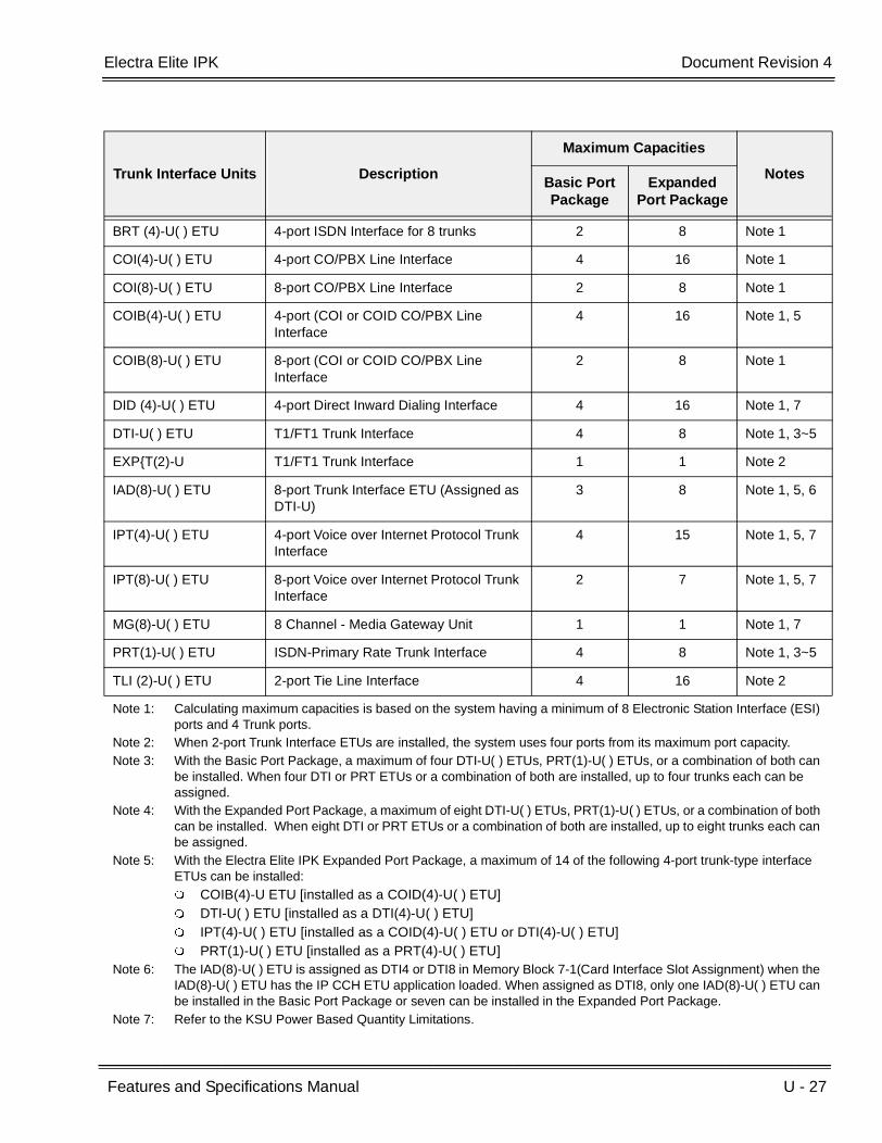
Electra Elite IPK Document Revision 4
Features and Specifications Manual U - 27
___________________________________________________________________________________
___________________________________________________________________________________
Trunk Interface Units Description
Maximum Capacities
NotesBasic Port Package
Expanded Port Package
BRT (4)-U( ) ETU 4-port ISDN Interface for 8 trunks 2 8 Note 1
COI(4)-U( ) ETU 4-port CO/PBX Line Interface 4 16 Note 1
COI(8)-U( ) ETU 8-port CO/PBX Line Interface 2 8 Note 1
COIB(4)-U( ) ETU 4-port (COI or COID CO/PBX Line Interface
4 16 Note 1, 5
COIB(8)-U( ) ETU 8-port (COI or COID CO/PBX Line Interface
2 8 Note 1
DID (4)-U( ) ETU 4-port Direct Inward Dialing Interface 4 16 Note 1, 7
DTI-U( ) ETU T1/FT1 Trunk Interface 4 8 Note 1, 3~5
EXPT(2)-U T1/FT1 Trunk Interface 1 1 Note 2
IAD(8)-U( ) ETU 8-port Trunk Interface ETU (Assigned as DTI-U)
3 8 Note 1, 5, 6
IPT(4)-U( ) ETU 4-port Voice over Internet Protocol Trunk Interface
4 15 Note 1, 5, 7
IPT(8)-U( ) ETU 8-port Voice over Internet Protocol Trunk Interface
2 7 Note 1, 5, 7
MG(8)-U( ) ETU 8 Channel - Media Gateway Unit 1 1 Note 1, 7
PRT(1)-U( ) ETU ISDN-Primary Rate Trunk Interface 4 8 Note 1, 3~5
TLI (2)-U( ) ETU 2-port Tie Line Interface 4 16 Note 2
Note 1: Calculating maximum capacities is based on the system having a minimum of 8 Electronic Station Interface (ESI) ports and 4 Trunk ports.
Note 2: When 2-port Trunk Interface ETUs are installed, the system uses four ports from its maximum port capacity.Note 3: With the Basic Port Package, a maximum of four DTI-U( ) ETUs, PRT(1)-U( ) ETUs, or a combination of both can
be installed. When four DTI or PRT ETUs or a combination of both are installed, up to four trunks each can be assigned.
Note 4: With the Expanded Port Package, a maximum of eight DTI-U( ) ETUs, PRT(1)-U( ) ETUs, or a combination of both can be installed. When eight DTI or PRT ETUs or a combination of both are installed, up to eight trunks each can be assigned.
Note 5: With the Electra Elite IPK Expanded Port Package, a maximum of 14 of the following 4-port trunk-type interface ETUs can be installed: COIB(4)-U ETU [installed as a COID(4)-U( ) ETU] DTI-U( ) ETU [installed as a DTI(4)-U( ) ETU] IPT(4)-U( ) ETU [installed as a COID(4)-U( ) ETU or DTI(4)-U( ) ETU] PRT(1)-U( ) ETU [installed as a PRT(4)-U( ) ETU]
Note 6: The IAD(8)-U( ) ETU is assigned as DTI4 or DTI8 in Memory Block 7-1(Card Interface Slot Assignment) when the IAD(8)-U( ) ETU has the IP CCH ETU application loaded. When assigned as DTI8, only one IAD(8)-U( ) ETU can be installed in the Basic Port Package or seven can be installed in the Expanded Port Package.
Note 7: Refer to the KSU Power Based Quantity Limitations.
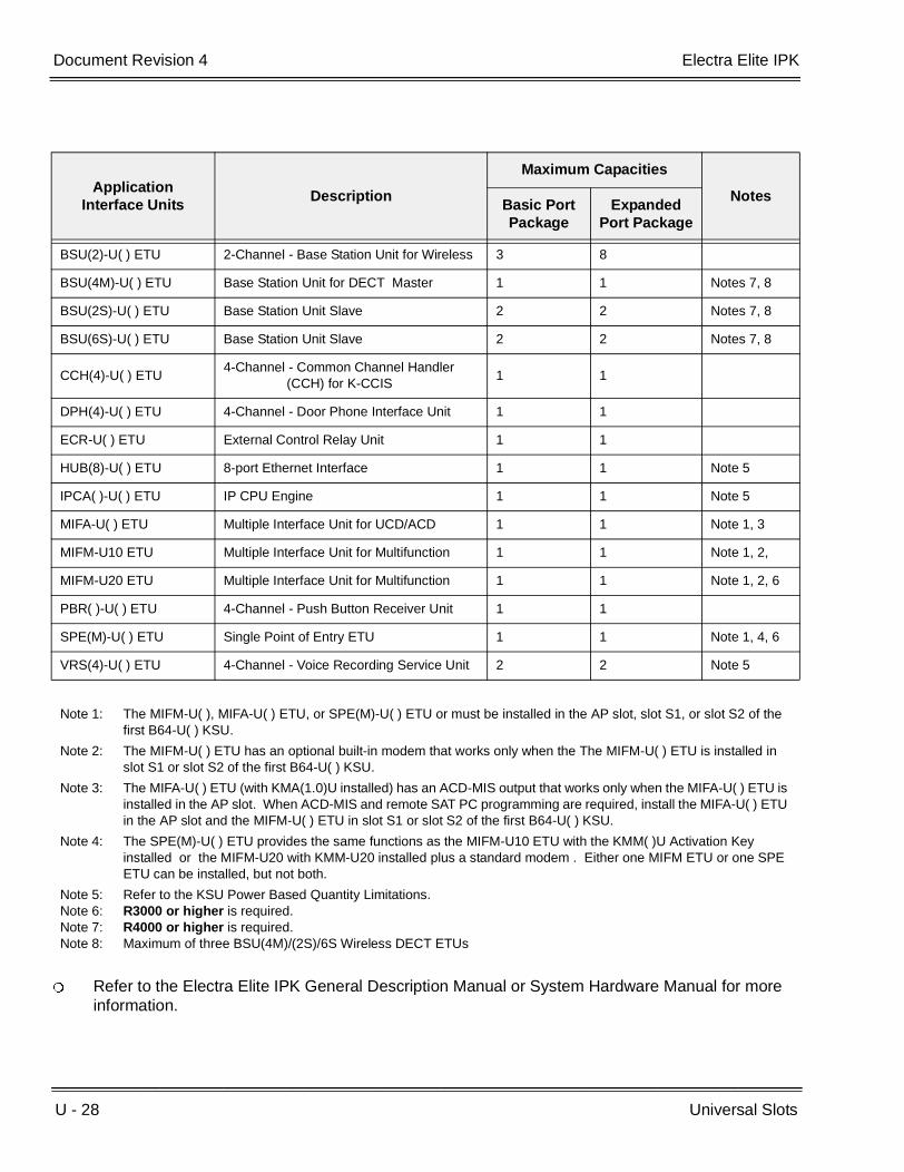
U - 28 Universal Slots
___________________________________________________________________________________
___________________________________________________________________________________Document Revision 4 Electra Elite IPK
Refer to the Electra Elite IPK General Description Manual or System Hardware Manual for more information.
Application Interface Units
Description
Maximum Capacities
NotesBasic Port Package
Expanded Port Package
BSU(2)-U( ) ETU 2-Channel - Base Station Unit for Wireless 3 8
BSU(4M)-U( ) ETU Base Station Unit for DECT Master 1 1 Notes 7, 8
BSU(2S)-U( ) ETU Base Station Unit Slave 2 2 Notes 7, 8
BSU(6S)-U( ) ETU Base Station Unit Slave 2 2 Notes 7, 8
CCH(4)-U( ) ETU4-Channel - Common Channel Handler
(CCH) for K-CCIS1 1
DPH(4)-U( ) ETU 4-Channel - Door Phone Interface Unit 1 1
ECR-U( ) ETU External Control Relay Unit 1 1
HUB(8)-U( ) ETU 8-port Ethernet Interface 1 1 Note 5
IPCA( )-U( ) ETU IP CPU Engine 1 1 Note 5
MIFA-U( ) ETU Multiple Interface Unit for UCD/ACD 1 1 Note 1, 3
MIFM-U10 ETU Multiple Interface Unit for Multifunction 1 1 Note 1, 2,
MIFM-U20 ETU Multiple Interface Unit for Multifunction 1 1 Note 1, 2, 6
PBR( )-U( ) ETU 4-Channel - Push Button Receiver Unit 1 1
SPE(M)-U( ) ETU Single Point of Entry ETU 1 1 Note 1, 4, 6
VRS(4)-U( ) ETU 4-Channel - Voice Recording Service Unit 2 2 Note 5
Note 1: The MIFM-U( ), MIFA-U( ) ETU, or SPE(M)-U( ) ETU or must be installed in the AP slot, slot S1, or slot S2 of the first B64-U( ) KSU.
Note 2: The MIFM-U( ) ETU has an optional built-in modem that works only when the The MIFM-U( ) ETU is installed in slot S1 or slot S2 of the first B64-U( ) KSU.
Note 3: The MIFA-U( ) ETU (with KMA(1.0)U installed) has an ACD-MIS output that works only when the MIFA-U( ) ETU is installed in the AP slot. When ACD-MIS and remote SAT PC programming are required, install the MIFA-U( ) ETU in the AP slot and the MIFM-U( ) ETU in slot S1 or slot S2 of the first B64-U( ) KSU.
Note 4: The SPE(M)-U( ) ETU provides the same functions as the MIFM-U10 ETU with the KMM( )U Activation Key installed or the MIFM-U20 with KMM-U20 installed plus a standard modem . Either one MIFM ETU or one SPE ETU can be installed, but not both.
Note 5: Refer to the KSU Power Based Quantity Limitations.Note 6: R3000 or higher is required.Note 7: R4000 or higher is required.Note 8: Maximum of three BSU(4M)/(2S)/6S Wireless DECT ETUs
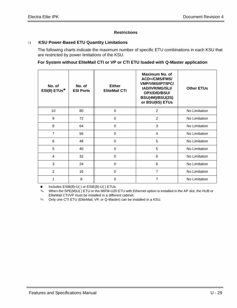
Electra Elite IPK Document Revision 4
Features and Specifications Manual U - 29
___________________________________________________________________________________
___________________________________________________________________________________
Restrictions
KSU Power-Based ETU Quantity Limitations
The following charts indicate the maximum number of specific ETU combinations in each KSU that are restricted by power limitations of the KSU.
For System without EliteMail CTI or VP or CTI ETU loaded with Q-Master application
No. ofESI(8) ETUs
No. ofESI Ports
Either EliteMail CTI
Maximum No. ofACD+/CMS/FMS/
VMP/VMS/IPT/IPC/IAD/IVR/MG/SLI/OPX/DID/BSU/
BSU(4M)/BSU(2S) or BSU(6S) ETUs
Other ETUs
10 80 0 2 No Limitation
9 72 0 2 No Limitation
8 64 0 3 No Limitation
7 56 0 4 No Limitation
6 48 0 5 No Limitation
5 40 0 5 No Limitation
4 32 0 6 No Limitation
3 24 0 6 No Limitation
2 16 0 7 No Limitation
1 8 0 7 No Limitation
Includes ESIB(8)-U( ) or ESIE(8)-U( ) ETUs. When the SPE(M)U( ) ETU or the MIFM-U20 ETU with Ethernet option is installed in the AP slot, the HUB or
EliteMail CTI/VP must be installed in a different cabinet. Only one CTI ETU (EliteMail, VP, or Q-Master) can be installed in a KSU.

U - 30 Universal Slots
___________________________________________________________________________________
___________________________________________________________________________________Document Revision 4 Electra Elite IPK
For System with EliteMail CTI or VP or CTI ETU loaded with Q-Master application
No. of ESI(8) ETUs
No. ofESI Ports
Either EliteMail CTI
Maximum No. ofACD+/CMS/FMS/
VMP/VMS/IPT/IPC/IAD/IVR/MG/SLI/OPX/DID/BSU/
BSU(4M)/BSU(2S) or BSU(6S) ETUs
Other ETUs
9 72 1 0 No Limitation
8 64 1 0 No Limitation
7 56 1 1 No Limitation
6 48 1 2 No Limitation
5 40 1 2 No Limitation
4 32 1 3 No Limitation
3 24 1 4 No Limitation
2 16 1 4 No Limitation
1 8 1 5 No Limitation
Includes ESIB(8)-U( ) or ESIE(8)-U( ) ETUs. When the SPE(M)U( ) ETU or the MIFM-U20 ETU with Ethernet option is installed in the AP slot, the HUB or
EliteMail CTI/VP must be installed in a different cabinet. Only one CTI ETU (EliteMail, VP, or Q-Master) can be installed in a KSU.
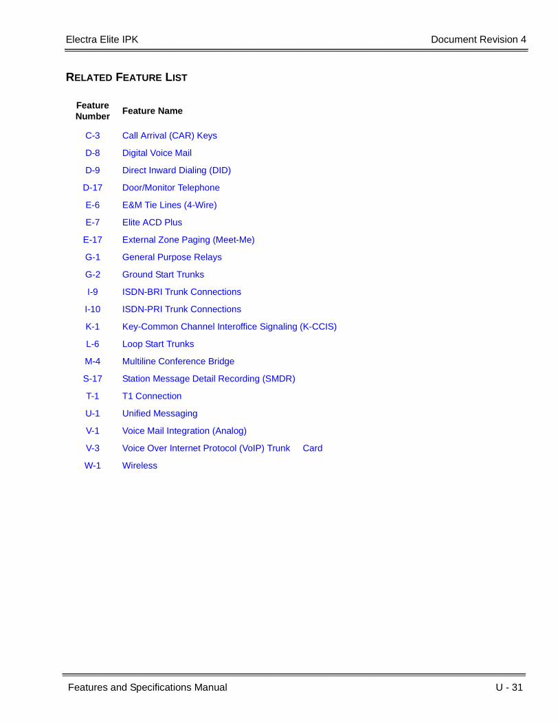
Electra Elite IPK Document Revision 4
Features and Specifications Manual U - 31
___________________________________________________________________________________
___________________________________________________________________________________
RELATED FEATURE LIST
Feature Number
Feature Name
C-3 Call Arrival (CAR) Keys
D-8 Digital Voice Mail
D-9 Direct Inward Dialing (DID)
D-17 Door/Monitor Telephone
E-6 E&M Tie Lines (4-Wire)
E-7 Elite ACD Plus
E-17 External Zone Paging (Meet-Me)
G-1 General Purpose Relays
G-2 Ground Start Trunks
I-9 ISDN-BRI Trunk Connections
I-10 ISDN-PRI Trunk Connections
K-1 Key-Common Channel Interoffice Signaling (K-CCIS)
L-6 Loop Start Trunks
M-4 Multiline Conference Bridge
S-17 Station Message Detail Recording (SMDR)
T-1 T1 Connection
U-1 Unified Messaging
V-1 Voice Mail Integration (Analog)
V-3 Voice Over Internet Protocol (VoIP) Trunk Card
W-1 Wireless
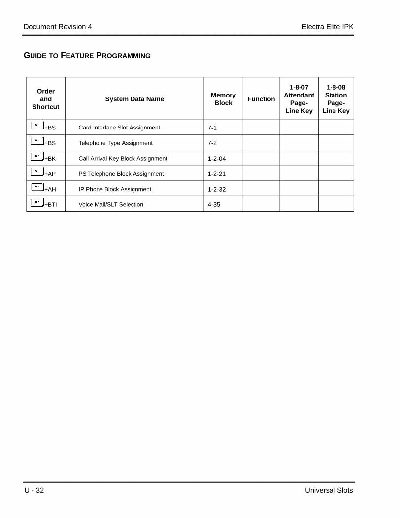
U - 32 Universal Slots
___________________________________________________________________________________
___________________________________________________________________________________Document Revision 4 Electra Elite IPK
GUIDE TO FEATURE PROGRAMMING
Orderand
ShortcutSystem Data Name
Memory Block
Function
1-8-07Attendant
Page-Line Key
1-8-08StationPage-
Line Key
+BS Card Interface Slot Assignment 7-1
+BS Telephone Type Assignment 7-2
+BK Call Arrival Key Block Assignment 1-2-04
+AP PS Telephone Block Assignment 1-2-21
+AH IP Phone Block Assignment 1-2-32
+BTI Voice Mail/SLT Selection 4-35

Features and Specifications Manual U - 33
___________________________________________________________________________________
___________________________________________________________________________________
Unsupervised Conference U-6
FEATURE DESCRIPTION
The Unsupervised Conference allows a Multiline Terminal user to exit an established conference call and leave the remaining parties to continue talking. This same user can then reenter the conference anytime.
SYSTEM AVAILABILITY
Terminal Type:
All Multiline Terminals
Required Components:
None
OPERATING PROCEDURES
To exit a conference:
1. Establish a conference call from a Multiline Terminal.
2. Press D (conferenced CO line keys turn red).
3. Multiline Terminal user now hears dial tone.
To enter a conference again:
1. Lift the handset or press E .
2. Press D .

U - 34 Unsupervised Conference
___________________________________________________________________________________
___________________________________________________________________________________Document Revision 4 Electra Elite IPK
SERVICE CONDITIONS
General:
Other stations cannot be interrupted (Barge-In) while on an Unsupervised Conference call.
When the Tandem Transfer Automatic Disconnect Time expires, the system automatically disconnects outside calls.
An alert tone is heard one minute before the Tandem Transfer Automatic Disconnect Time disconnects the outside caller.
ICM hold, Live Record, and Voice Over cannot be used during an Unsupervised Conference.
When the CO provides disconnect when one outside party hangs up, the other outside party is disconnected.
Restrictions:
User can join only one Unsupervised Conference at a time.
The Unsupervised Conference feature is available only on Multiline Terminals.
Only 16 conference calls (Add-On and Unsupervised) may be in progress at the same time.
Other stations cannot enter an Unsupervised Conference.
GUIDE TO FEATURE PROGRAMMING
Orderand
ShortcutSystem Data Name
Memory Block
Function
1-8-07AttendantPage-Line
Key
1-8-08StationPage-
Line Key
+BTS Class of Service (Station) Feature Selection 2 1-8-08 4-8
+BTTStation to Class of Service Feature Assignment
4-17
+ATTandem Transfer Automatic Disconnect Time Selection
1-4-00
+ATTandem Transfer SMDR Print Extension Assignment
1-4-04
When the system is at default this Memory Block must be programmed for the feature to be used.

Features and Specifications Manual U - 35
___________________________________________________________________________________
___________________________________________________________________________________
User Programming Ability U-7
FEATURE DESCRIPTION
A Station user can perform programming functions. Station Speed Dial and Ringing Line Preference are two features programmable from a station. Using NEC System Administration Terminal End-User Software, approximately 35 additional features can be programmed by the user.
ENHANCEMENT(S)
Release 3000:
With R3000 or higher, the user can program LCD Name Assignment of Feature Access keys on DTH-16LD-1 telephones.
SYSTEM AVAILABILITY
Terminal Type:
All Multiline Terminals
Required Components:
None
OPERATING PROCEDURES
Refer to Related Features for Operating Procedures.
SERVICE CONDITIONS
Multiline Terminals must be idle and on-hook when programming any operation.

U - 36 User Programming Ability
___________________________________________________________________________________
___________________________________________________________________________________Document Revision 4 Electra Elite IPK
RELATED FEATURES LIST
Feature Number
Feature Name
E-2 Electra Elite IPK Terminals
F-2 Feature Access – User Programmable
N-2 Nesting Dial
R-8 Ringing Line Preference
S-12 Speed Dial Stored Characters
S-11 Speed Dial – Station

Features and Specifications Manual V - 1
___________________________________________________________________________________
___________________________________________________________________________________
Voice Mail Integration (Analog) V-1
FEATURE DESCRIPTION
Voice Mail Integration (Analog) provides the interface between the Expanded Port Package and the Basic Port Package and a locally-provided analog Voice Mail system. When a station is forwarded to the Voice Mail system and a station user calls that forwarded station, the call goes directly to the individual personal mail box. When the Voice Mail system has the ability, a message can be sent to the station indicating a Voice Mail Message was received. The two packages can support a maximum of 16 ports for Analog Voice Mail when Digital Voice Mail integration or Built-in Voice Mail is not available.
SYSTEM AVAILABILITY
Terminal Type:
Not Applicable
Required Components:
SLI(4)-U( ) ETU or SLI(8)-U( ) ETU
OPERATING PROCEDURES
To retrieve a message using a Multiline Terminal with or without LCD (large LED flashing):
1. Lift the handset.
2. Dial the Voice Mail station number to access your mailbox.
3. Follow the Voice Mail system instructions when answered.

V - 2 Voice Mail Integration (Analog)
___________________________________________________________________________________
___________________________________________________________________________________Document Revision 4 Electra Elite IPK
To retrieve a message using a Single Line Telephone (Message Wait LED on):
1. Lift the handset.
2. Dial the Voice Mail station number to access your mailbox.
3. Follow the Voice Mail system instructions when answered.
SERVICE CONDITIONS
General:
A maximum of four SLI(4)-U( ) ETUs or two SLI(8)-U( ) ETUs can be installed to support 16 analog Voice Mail ports.
Some Voice Mail systems cannot leave a message indication.
A call transferred from a Voice Mail port that is not answered in three minutes recalls to the Voice Mail port. No digits are sent.
When a station is programmed for Multiple Call Forward (e.g., 100 CFWD – 101 CFWD – VM Hunt Group) and an internal call is made to station 100, the caller receives the mailbox for station 100.
The AP(R)-R/AP(A)-R Unit, APR/APA-U Unit, and SLT(1)-U( ) ADP do not support Voice Mail Integration.
Set/cancel Voice Mail Message Waiting only from a Voice Mail port.
When a call is complete, a disconnect signal is sent to the VM port.
For connecting Voice Mail systems, refer to the applicable Engineering Technical Information (ETI) bulletins.
When required by locally provided Voice Mail systems, up to four digits can be sent before a station number to access a user mailbox.
The Large LED flashes red for message from Voice Mail or green for message from an Attendant.
An analog voice mail system cannot be used to support Centralized Voice Mail (with E&M Tie Lines) or Voice Mail Integration – K-CCIS (Centralized VM).
Restrictions:
SLI(4)/(8)-U( ) ETU ports assigned as voice mail cannot establish an Add-On Conference Call.
When 5-, 6-, or 7-digit station numbers are used, this feature is not available.
When Voice Mail Message Waiting must be sent across the K-CCIS link to a remote system, the Closed Number Blocks must be used.

Electra Elite IPK Document Revision 4
Features and Specifications Manual V - 3
___________________________________________________________________________________
___________________________________________________________________________________
RELATED FEATURES LIST
GUIDE TO FEATURE PROGRAMMING
Feature Number
Feature Name
C-18 Centralized Voice Mail (with E&M Tie Lines)
D-8 Digital Voice Mail
S-16 Station Hunt
Orderand
ShortcutSystem Data Name
Memory Block
Function
1-8-07AttendantPage-Line
Key
1-8-08StationPage-
Line Key
+BTI Voice Mail/SLT Selection 4-35
+BTT Intercom Master Hunt Number Selection 4-14
+BTTIntercom Master Hunt Number Forward Assignment
4-15
+AVVoice Mail Quick Transfer Master Hunt Number
1-8-26
+BA Intercom Feature Access Code Assignment 1-2-24 007
+BTSClass of Service (Station) Feature Selection 2 1-8-08 1-1, 2-5,
6-2
+BTTStation to Class of Service Feature Assignment
4-17
+BA
Access Code (1-, 2-, or 3-Digit) Assignment 1-1-46/47/48
020 ~ 025,030,032~034,140~143
+BCT DIT Assignment 3-42
+BCT ANA Assignment 3-43
+AV Voice Mail Digit Add Assignment 1-3-07
+AV Voice Mail DTMF Delay Time Selection 1-3-08
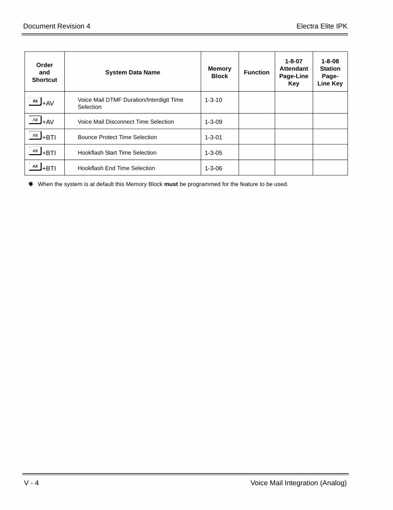
V - 4 Voice Mail Integration (Analog)
___________________________________________________________________________________
___________________________________________________________________________________Document Revision 4 Electra Elite IPK
+AVVoice Mail DTMF Duration/Interdigit Time Selection
1-3-10
+AV Voice Mail Disconnect Time Selection 1-3-09
+BTI Bounce Protect Time Selection 1-3-01
+BTI Hookflash Start Time Selection 1-3-05
+BTI Hookflash End Time Selection 1-3-06
When the system is at default this Memory Block must be programmed for the feature to be used.
Orderand
ShortcutSystem Data Name
Memory Block
Function
1-8-07AttendantPage-Line
Key
1-8-08StationPage-
Line Key

Features and Specifications Manual V - 5
___________________________________________________________________________________
___________________________________________________________________________________
Voice Mail Message Indication on Line
Keys V-2
FEATURE DESCRIPTION
Voice Mail MSG waiting on Line keys indicates an existing or new voice mail message on Line Keys or DSS/BLF keys.
SYSTEM AVAILABILITY
Terminal Type:
All Multiline Terminals
Required Components:
VMS(2)-U( ), VMS(4)-U( ), or VMS(8)-U( ) ETUFMS(2)-U( ), FMS(4)-U( ), FMS(8)-U( ) or any Analog VM with message ability
OPERATING PROCEDURES
To program a Feature Access Key for VM MSG key:
1. Press A .
2. Press B .
3. Press the Feature Access Key.
4. Dial A.
5. Dial station number or mailbox number.
6. Press A .

V - 6 Voice Mail Message Indication on Line Keys
___________________________________________________________________________________
___________________________________________________________________________________Document Revision 4 Electra Elite IPK
To program a One-Touch Key for VM MSG key:
1. Press A .
2. Press B .
3. Press the One-Touch Key.
4. Dial A.
5. Dial station number or mailbox number.
6. Press A .
SERVICE CONDITIONS
General:
The state of a One-Touch or Feature Access key is indicated by the red LED as follows:
On Steady Registered Box Number Station is busy.
Flashing 0.25ON/0.25 OFF Registered station is in Call Forward-All Call or Do Not Disturb.
Flashing 0.5 On/0.5 OFF Registered station was set by pressing the Function key.
Fast flash 0.125 ON/0.125 OFF Mailbox contains an unplayed message.
OFF Station is idle or Voice Mailbox is empty.
When the Mailbox registered for multiple Line Keys or One-Touch Keys contains a message, all programmed keys flash to indicate that the mailbox contains an unplayed message.
This feature also supports Analog Voice Mail Systems.
When the user of an invalid system station with a mailbox number assigned to a Feature Access or One-Touch key presses the One-Touch or Feature Access key while the LED is off, ERROR is displayed, and an error tone is generated.
When the user of an invalid system station with a mailbox number assigned to a Feature Access or One-Touch key presses the One-Touch or Feature Access key while the LED indicates MSG waiting, the caller is logged into that mailbox.
When the user of a valid system station with a mailbox number assigned to a Feature Access or One-Touch key presses the One-Touch or Feature Access key while the LED indicates MSG waiting, an internal call is placed to that station.

Electra Elite IPK Document Revision 4
Features and Specifications Manual V - 7
___________________________________________________________________________________
___________________________________________________________________________________
Restrictions:
The following numbers can be registered as allowable mailbox numbers for up to a maximum of 200 voice mailboxes:
2-Digit 10~89
3-Digit 100~899
4-Digit 1000~8999
Voice Mail MSG Waiting has priority over any other state of the flashing line key or One-Touch Key.
When Voice Mail Message Waiting must be sent across the K-CCIS link to a remote system, the Closed Number Blocks must be used.
RELATED FEATURES LIST
GUIDE TO FEATURE PROGRAMMING
Feature Number
Feature Name
D-8 Digital Voice Mail
S-16 Station Hunt
U-7 User Programming Ability
Orderand
ShortcutSystem Data Name
Memory Block
Function
1-8-07AttendantPage-Line
Key
1-8-08StationPage-
Line Key
+BS Telephone Type Assignment 7-2
+BTM Multiline Terminal Type Selection 4-50
+BTS Class of Service (Station) Feature Selection 2 1-8-08 6-2
+BTT Station to Class of Service Feature Assignment
4-17
+BN Line Key Selection 2-05
+BN Line Key Selection for Tenant Mode 2-06

V - 8 Voice Mail Message Indication on Line Keys
___________________________________________________________________________________
___________________________________________________________________________________Document Revision 4 Electra Elite IPK
+BTM Line Key Selection for Telephone Mode 4-12
+BTD Attendant Add-On Console Key Selection 1-6-05
+AVVoice Mail Quick Transfer Master Hunt Number
1-8-26
+BS Station Number Assignment 4-10
+BTT Intercom Master Hunt Number 4-14
+BTTIntercom Master Hunt Number Forward Assignment
4-15
Orderand
ShortcutSystem Data Name
Memory Block
Function
1-8-07AttendantPage-Line
Key
1-8-08StationPage-
Line Key
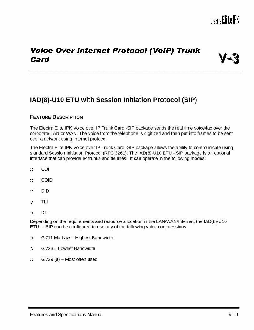
Features and Specifications Manual V - 9
___________________________________________________________________________________
___________________________________________________________________________________
Voice Over Internet Protocol (VoIP) Trunk
Card V-3
IAD(8)-U10 ETU with Session Initiation Protocol (SIP)
FEATURE DESCRIPTION
The Electra Elite IPK Voice over IP Trunk Card -SIP package sends the real time voice/fax over the corporate LAN or WAN. The voice from the telephone is digitized and then put into frames to be sent over a network using Internet protocol.
The Electra Elite IPK Voice over IP Trunk Card -SIP package allows the ability to communicate using standard Session Initiation Protocol (RFC 3261). The IAD(8)-U10 ETU - SIP package is an optional interface that can provide IP trunks and tie lines. It can operate in the following modes:
COI
COID
DID
TLI
DTI
Depending on the requirements and resource allocation in the LAN/WAN/Internet, the IAD(8)-U10 ETU - SIP can be configured to use any of the following voice compressions:
G.711 Mu Law – Highest Bandwidth
G.723 – Lowest Bandwidth
G.729 (a) – Most often used
V - 10 Voice Over Internet Protocol (VoIP) Trunk Card
___________________________________________________________________________________
___________________________________________________________________________________Document Revision 4 Electra Elite IPK
The IAD(8)-U10 ETU - SIP can be assigned in any of the following configurations:
A two-port TLI(2)-U10 ETU
A four-port DID(4)/COI(4)/ COID(4)-U10 ETU
An eight-port COI(8)/ COID(8)-U10 ETU
A DTI ETU using 8 channels that can be installed in interface slots supporting these ETUs.
The LAN/WAN or internet connection is provided by a 10/100 Base T Ethernet.
The ETU operating mode can be configured per ETU, but not per port.
SYSTEM AVAILABILITY
Terminal Type:
All Multiline Terminals
Required Components:
IAD(8)-U10 ETU -SIP package
OPERATING PROCEDURES
Use any combination of manual dialing, Save and Repeat, Save and Store, Last Number Redial, Station Speed Dial, and System Speed dial.
SERVICE CONDITIONS
Data Assignment:
The IAD(8)-U10 ETU can be configured in DTI8.
General:
The LIVE LED flashes when the ETU is receiving power from the KSU.
Two LEDs on the RJ-45 Connector indicate the Ethernet status. A yellow LED indicates the Ethernet Link is transmitting data, and the green LED indicates the Ethernet Link is receiving data.
Eight STATUS LEDs are provided to indicate the status of an associated trunk or channel when selected.
Sixty-four IP trunks (Combination of Ground Start, Loop Start, E&M Tie Lines, and DID Trunk configurations) can be installed in an Electra Elite IPK KSU.

Electra Elite IPK Document Revision 4
Features and Specifications Manual V - 11
___________________________________________________________________________________
___________________________________________________________________________________
Sixty-four trunks (Ground Start, Loop Start, E&M Tie Lines, and DID Trunks) can be installed in an Electra Elite IPK system.
RELATED FEATURES LIST
IAD(8)-U10 ETU with H.323 Protocol
FEATURE DESCRIPTION
The Electra Elite IPK Voice over IP Trunk Card H-323 package sends the real time voice/fax over the corporate LAN or WAN. The voice from the telephone is digitized and then put into frames to be sent over a network using Internet protocol.
The Electra Elite IPK Voice over IP Trunk Card H-323 package allows the ability to communicate using standard H-323 (Normal and Fast Start) Protocol and allows connectivity to any H-323 standards compliant voice gateway and gatekeeper. This VOIP Trunk Card also provides Registration and Authentication Server (RAS) support with the ability to register with an RAS Server and use Gatekeeper for dynamic call routing.
The IAD(8)-U10 ETU - H.323 is an optional interface that can provide IP trunks and tie lines. It can operate in the following modes:
COI
COID
DID
TLI
DTI
Feature Number
Feature Name
C-22 CO/PBX, Tie Line Digit Restriction
D-9 Direct Inward Dialing (DID)
E-6 E&M Tie Lines (4-Wire)
L-6 Loop Start Trunks
U-4 Uniform Numbering Network

V - 12 Voice Over Internet Protocol (VoIP) Trunk Card
___________________________________________________________________________________
___________________________________________________________________________________Document Revision 4 Electra Elite IPK
Depending on the requirements and resource allocation in the LAN/WAN/Internet, the IAD(8)-U10 ETU - H.323 can be configured to use any of the following voice compressions:
G.711 Mu Law – Highest Bandwidth
G.723 – Lowest Bandwidth
G.729 (a) – Most often used
The IAD(8)-U10 ETU - H.323 can be assigned in any of the following configurations:
A 2-port TLI(2)-U10 ETU
A 4-port DID(4)/COI(4)/ COID(4)-U10 ETU
An 8-port COI(8)/ COID(8)-U10 ETU
A DTI ETU using eight channels that can be installed in interface slots supporting these ETUs.
The LAN/WAN or internet connection is provided by a 10/100 Base T Ethernet.
The ETU operating mode can be configured per ETU, but not per port.
SYSTEM AVAILABILITY
Terminal Type:
All Multiline Terminals
Required Components:
IAD(8)-U10 ETU - H.323 package
OPERATING PROCEDURES
Use any combination of manual dialing, Save and Repeat, Save and Store, Last Number Redial, Station Speed Dial, and System Speed dial.
SERVICE CONDITIONS
Data Assignment:
The IAD(8)-U10 ETU - H322 can communicate with other H.323v2 products such as PBX or Cisco Call Manager. The ETU must be configured in TLI or DID Mode only to communicate.
The IAD(8)-U10 ETU - H322 can be configured in DTI8.

Electra Elite IPK Document Revision 4
Features and Specifications Manual V - 13
___________________________________________________________________________________
___________________________________________________________________________________
General:
The LIVE LED flashes when the ETU is receiving power from the KSU.
Two LEDs on the RJ-45 Connector indicate the Ethernet status. A yellow LED indicates the Ethernet Link is transmitting data, and the green LED indicates the Ethernet Link is receiving data.
Eight STATUS LEDs are provided to indicate the status of an associated trunk or channel when selected.
Sixty-four IP trunks (Combination of Ground Start, Loop Start, E&M Tie Lines, and DID Trunk configurations) can be installed in an Electra Elite IPK KSU.
Sixty-four trunks (Ground Start, Loop Start, E&M Tie Lines, and DID Trunks) can be installed in an Electra Elite IPK system.
RELATED FEATURES LIST
Feature Number
Feature Name
C-22 CO/PBX, Tie Line Digit Restriction
D-9 Direct Inward Dialing (DID)
E-6 E&M Tie Lines (4-Wire)
L-6 Loop Start Trunks
U-4 Uniform Numbering Network

V - 14 Voice Over Internet Protocol (VoIP) Trunk Card
___________________________________________________________________________________
___________________________________________________________________________________Document Revision 4 Electra Elite IPK
THIS PAGE INTENTIONALLY LEFT BLANK

Features and Specifications Manual V - 15
___________________________________________________________________________________
___________________________________________________________________________________
Voice Over Split V-4
FEATURE DESCRIPTION
By dialing an Access Code, a station user can voice override the conversation between another station user and another party. When the conversation is interrupted, only the station that received the Voice Over hears it.
SYSTEM AVAILABILITY
Terminal Type:
All Multiline Terminals
Required Components:
None
OPERATING PROCEDURES
To originate Voice Over using a Multiline Terminal:
1. Receive call waiting tone.
2. Dial Access CodeF(default) to Voice Over. Override tone is provided to the called party.
3. Talk to the called station user. Only the voice of the originator is sent to the called party; the voice of the called party is not sent to the originator.
To originate Voice Over using a Single Line Telephone:
1. Receive call waiting tone.
2. Dial Access CodeFto Voice Over. An override tone is provided to the called station user.

V - 16 Voice Over Split
___________________________________________________________________________________
___________________________________________________________________________________Document Revision 4 Electra Elite IPK
3. Talk to the called station user. Only the voice of the originator is sent to the called party; the voice of the called party is not sent to the originator.
To answer using a Multiline Terminal (Broker's call):
1. Receive Voice Over.
2. Press H to answer the calling party. The other party is automatically placed on hold ( F flashes green).
3. Press F to switch over to talk to the other party.
4. Talk to the called party.
Repeatedly pressing F alternates the talk path between both calls.
To answer using a Multiline Terminal (Whisper Page):
1. Receive Voice Over.
2. Press A and dialFE (or a Feature Access key/One-Touch key programmed with the Access Code) to switch over to talk with the calling station user if needed.
3. The called station user can then press A and dialFE to switch back to the other party.
SERVICE CONDITIONS
General:
Voice Over to a Single Line Telephone is not recommended because cross talk is inherent in the side tone of analog telephones.
Voice Over is canceled when the following operations are used:
The calling party goes on-hook.
The called Multiline Terminal user presses the Conference or Transfer key. The current call is placed on hold. The called party receives an internal dial tone, and the calling party receives a burst tone.
The called Multiline Terminal user presses the Recall or Drop key. The called party seizes the same outside line. The calling party receives a busy tone.
An internal party who is talking with the called Multiline Terminal user presses the Hold key. The called party receives Music On Hold. The calling party receives a call waiting tone.

Electra Elite IPK Document Revision 4
Features and Specifications Manual V - 17
___________________________________________________________________________________
___________________________________________________________________________________
When a Multiline Terminal user performs Voice Over, the speech path is one-way from the originator to the destination.
The Voice Over Access Code can be assigned on a Flexible Programmable Line key or One-Touch key.
An override tone is sent to both calling and called parties.
A Single Line Telephone user can receive Voice Over.
After a Tone Override is heard, Voice Over can be set.
When a Feature Access key or One-Touch key (programmed with the Whisper Page Access Code) is pressed, the LED lights while responding to the page.
When a station has a Handsfree Unit programmed, the Voice Over call can be received and answered handsfree.
Even when Data Line Security is assigned to a station, Voice Over (Originate/Receive) can be activated. Voice Over blocks the override tone from the handset.
Restrictions:
Voice Over can be accomplished only after receiving a call waiting tone.
A Multiline Terminal can receive only one Voice Over at a time.
A Multiline Terminal user cannot answer a Voice Over with an internal call on hold, while talking on an internal call.
Voice Override is not allowed for Add-On Conference calls.
An attempt to Voice Over a Multiline/Single Line Terminal can be denied for the following reasons:
Multiline Terminal is in DND (Do Not Disturb) Mode
Automatic Redial is activated
During Station Programming
During Incoming Ringing
During Internal/External Paging
During a Conference Call
During a Conference Call on Hold
Terminal is on Internal Hold
Terminal has a call on Internal Hold

V - 18 Voice Over Split
___________________________________________________________________________________
___________________________________________________________________________________Document Revision 4 Electra Elite IPK
All Conference channels are busy
During Handsfree Answerback
GUIDE TO FEATURE PROGRAMMING
Orderand
ShortcutSystem Data Name
Memory Block
Function
1-8-07AttendantPage-Line
Key
1-8-08StationPage-
Line Key
+BTS Class of Service (Station) Feature Selection 2 1-8-08 1-8, 3-3
+BTTStation to Class of Service Feature Assignment
4-17
+BA Intercom Feature Access Code Assignment 1-2-24 006
Features and Specifications Manual V - 19
___________________________________________________________________________________
___________________________________________________________________________________
Voice Prompt V-5
FEATURE DESCRIPTION
Voice Prompt provides voice guidance for assisting station users. The voice prompt replaces the call waiting tone and/or internal dial tone.
SYSTEM AVAILABILITY
Terminal Type:
All Stations
Required Components:
VRS(4)-U( ) ETU
OPERATING PROCEDURES
To use this feature:
1. Go off-hook.
2. Listen to the Voice Prompt voice message such as:
Dial 9 to place a CO call.
Dial 0 for Attendant.
Dial 101 for customer service.
3. Dial AKA.
4. Instead of a call waiting tone, the Voice Prompt provides a message such as:
This line is in use now.
Please wait for a minute.
Dial if you wish to set a Tone Override.
V - 20 Voice Prompt
___________________________________________________________________________________
___________________________________________________________________________________Document Revision 4 Electra Elite IPK
5. Dial J for the Tone Override.
To record a Voice Prompt message:
1. Go off-hook.
2. Dial the VRS voice message record/verify/erase Access Code.
3. Dial operation:
A Recording
B Confirmation
C Erasing
4. Dial operation:
B Voice Prompt Message
5. Dial operation:
A Message for Dial Tone
B Message for Call Waiting Tone
6. Record message.
7. Go on-hook.
During Message Recording, the LCD indicates the time remaining for recording the message.
SERVICE CONDITIONS
General:
The Voice Prompt message should be recorded by the user.
Messages are retained for approximately one hour during power outages.
Voice Prompt can start in the middle of a message when all dial tones or call waiting tone messages are already busy and another station accesses one of these messages.
Voice Prompt can be generated only on an intercom call.
The microphone can be used instead of a handset for recording messages.
When Voice Prompt message is not programmed, and the station is assigned to hear Voice Prompt messages, normal dial tone or call waiting tone is provided.

Electra Elite IPK Document Revision 4
Features and Specifications Manual V - 21
___________________________________________________________________________________
___________________________________________________________________________________
When you try to record, confirm, or erase a message while it is being played, you hear a busy tone.
When all VRS(4)-U( ) ETU channels with Voice Prompt messages are busy (playing messages other than Voice Prompts or in record mode), normal dial tone or a call waiting tone is heard.
Previously recorded Voice Prompt messages are erased when a new message is recorded.
The chart below shows the possible combinations of recording times and the number of messages per VRS(4)-U( ) ETU channel. Each channel has a maximum of 240 seconds recording time.
Restrictions:
Only two VRS(4)-U( ) ETUs can be installed in an Electra Elite IPK for eight voice playback channels.
GUIDE TO FEATURE PROGRAMMING
MessageLength
Number ofMessages
15 sec. 16
30 sec. 8
60 sec. 4
120 sec. 2
Orderand
ShortcutSystem Data Name
Memory Block
Function
1-8-07AttendantPage-Line
Key
1-8-08StationPage-
Line Key
+AR VRS Message Recording Time Selection 1-8-12
+AR VRS Message Function Assignment 1-8-13
+AR Voice Prompt to Tone Assignment 1-8-16
+BA Access Code (1-, 2-, or 3-Digit) Assignment 1-1-46/47/48
501
+BTS Class of Service (Station) Feature Selection 2 1-8-08 2-6
+BTT Station to Class of Service Feature Assignment
4-17
+BTT Voice Prompt Selection 4-36
When the system is at default this Memory Block must be programmed for the feature to be used.

V - 22 Voice Prompt
___________________________________________________________________________________
___________________________________________________________________________________Document Revision 4 Electra Elite IPK
THIS PAGE INTENTIONALLY LEFT BLANK

Features and Specifications Manual W - 1
___________________________________________________________________________________
___________________________________________________________________________________
Wireless W-1
FEATURE DESCRIPTION
Using a Personal Station, Dterm PS II, the features and benefits of the desktop telephone are provided without the inconvenience of having to stay close to the Desktop. A BSU(2)-U( ) ETU interfaces the KSU to an antenna unit called a Zone Transceiver (ZT II). These units are placed throughout the facility to manage calls through a network for wireless communication using a Dterm PS II.
ENHANCEMENT(S)
With R2000 or higher, a PSII user can perform a Trunk-to-Trunk Transfer or place a 1-terminal to 2-outside parties conference call.
SYSTEM AVAILABILITY
Terminal Type:
Dterm PS II
Required Components:
Dterm PS II
BSU(2)-U( ) ETU
ZT II-U( ) ETU
ACA-U Unit (1 per ZTII as required)
CLKG-U( ) Unit
MIFM-U( ) ETU
W - 2 Wireless
___________________________________________________________________________________
___________________________________________________________________________________Document Revision 4 Electra Elite IPK
WIRELESS FEATURES
ANNOUNCEMENT-PS NO ANSWER/ANNOUNCEMENT – PS OUT OF ZONE
GENERAL DESCRIPTION
This feature allows a call from a Dterm PS II that cannot be paged in a programmed time to be routed to a display that indicates the Dterm PS II is Out of Zone and cannot be answered.
OPERATING PROCEDURES
Operation is Automatic.
AUTOMATIC RELEASE – OUT OF ZONE CALLS
GENERAL DESCRIPTION
When a Dterm PS II caller either crosses the service area boundary or enters a zone where all channels are busy and communication is impossible, the call is disconnected automatically, and the other party receives reorder tone or Out of Area display.
OPERATING PROCEDURES
Operation is automatic.
CALL FORWARDING – NOT AVAILABLE
GENERAL DESCRIPTION
When a Dterm PS II is powered off or Out of Zone, a call directed to it is forwarded to a VMS, and a message can be recorded to the VMS and checked from the Dterm PS II. The VMS can page the Dterm
PS II automatically after the Voice Mail message is recorded.

Electra Elite IPK Document Revision 4
Features and Specifications Manual W - 3
___________________________________________________________________________________
___________________________________________________________________________________
OPERATING PROCEDURES
Refer to the following features in the Electra Elite IPK Wireless Manual:
Call Forward – All Call
Call Forward – Busy/No Answer
Call Forward – Off - Premise
Call Forward – Split
CALLING NAME DISPLAY – Dterm PS II
GENERAL DESCRIPTION
When an incoming call is ringing, or a hold call terminates on the Dterm PS II, the calling party name is displayed on the LCD.
OPERATING PROCEDURES
Refer to Electra Elite IPK Wireless Manuall for Station Name Assignment.
CALLING NUMBER DISPLAY – Dterm PS II
GENERAL DESCRIPTION
This feature allows the Station Number of an incoming call to be displayed on the LCD of the Dterm PS II receiving the call.
OPERATING PROCEDURES
Operation is automatic.
W - 4 Wireless
___________________________________________________________________________________
___________________________________________________________________________________Document Revision 4 Electra Elite IPK
DTMF SIGNAL SENDER
GENERAL DESCRIPTION
This feature allows a Dterm PS II user to send a DTMF tone to the called party terminal or Voice Mail.
OPERATING PROCEDURES
To send DTMF Tone:
1. Press a digit key during communication.
2. The Elite System automatically sends the applicable tone to the called party.
HAND OVER
GENERAL DESCRIPTION
When signal transmission quality becomes a problem, the Dterm PS II originates another call automatically to seize another radio channel and force the Electra Elite to handover the call to another zone transceiver to maintain quality.
OPERATING PROCEDURES
Operation is automatic.
INDIVIDUAL Dterm PS II CALLING
GENERAL DESCRIPTION
The calling party can page the individual Dterm PS II.

Electra Elite IPK Document Revision 4
Features and Specifications Manual W - 5
___________________________________________________________________________________
___________________________________________________________________________________
OPERATING PROCEDURES
To page a Dterm PS II:
1. Dial its unique number to call the designated Dterm PS II.
2. If the calling number is available, the lower number digits are displayed on the LCD of the called Dterm PS II.
3. The called Dterm PS II user can press LK1 to answer.
LAST NUMBER REDIAL
GENERAL DESCRIPTION
The Dterm PS II user can store the number for the previous five calls. The stacked numbers are sequentially displayed on the LCD to allow the user to make an outgoing call by selecting the desired number from the display.
OPERATING PROCEDURES
To make an outgoing call:
1. Use Overlap or Preset Dialing to make an outgoing call.
2. The number dialed is automatically stored.
OUT OF ZONE INDICATION
GENERAL DESCRIPTION
A warning tone and LCD display indicate when the Dterm PS II user moves out of the service area.
OPERATING PROCEDURES
Operation is automatic.

W - 6 Wireless
___________________________________________________________________________________
___________________________________________________________________________________Document Revision 4 Electra Elite IPK
OVERLAP DIALING
GENERAL DESCRIPTION
The Dterm PS II user accesses dial tone and dials the indicated number to originate a call.
OPERATING PROCEDURES
To originate a call:
1. The Dterm PS II user can press LK1 to access dial tone.
2. The user dials the number.
3. The dialed number is displayed on the LCD.
PRESET DIALING
GENERAL DESCRIPTION
The Dterm PS II user can confirm the number to be dialed before originating a call.
OPERATING PROCEDURES
To dial a number:
1. Dial the desired number.
2. The number is stored and displayed on the LCD.
3. After confirming the number, press LK1.

Electra Elite IPK Document Revision 4
Features and Specifications Manual W - 7
___________________________________________________________________________________
___________________________________________________________________________________
Dterm PS AUTHORIZATION
GENERAL DESCRIPTION
The Dterm PS II user can confirm the identity to prevent an unauthorized Dterm PS II from accessing the system.
OPERATING PROCEDURES
Operation is automatic.
Identity is confirmed between the Electra Elite IPK and Dterm PS II by checking the unique key information of the Dterm PS II.
Dterm PS II LOCATION REGISTRATION
GENERAL DESCRIPTION
The Electra Elite IPK system can supervise the location of each Dterm PS II and allow Call termination after receiving the location registration request.
OPERATING PROCEDURES
Operation is automatic.
RADIO CHANNEL CHANGEOVER
GENERAL DESCRIPTION
Speech quality and interference are monitored. When the quality is poor or interference makes communication difficult, automatic changeover to another channel improves the speech quality and eliminates interference.
OPERATING PROCEDURES
Operation is automatic.
W - 8 Wireless
___________________________________________________________________________________
___________________________________________________________________________________Document Revision 4 Electra Elite IPK
SPEECH ENCRYPTION
GENERAL DESCRIPTION
A call is protected from being tapped.
OPERATING PROCEDURES
Operation is automatic.
SPEED DIAL – PS
GENERAL DESCRIPTION
The Dterm PS II user can dial frequently called numbers using 2-digit abbreviated call codes.
OPERATING PROCEDURES
Refer to Speed Dial in the Dterm PS II User Guide.
VOICE MAIL INDICATION
GENERAL DESCRIPTION
When a message is mailed to the Dterm PS II, the envelope icon is displayed on its LCD along with a short ring tone.
OPERATING PROCEDURES
To retrieve a voice mail message:
1. Press LK1 to generate dial tone.
2. Dial the VM pilot number.
3. Follow the instructions given by the voice mail.
4. Listen to the message.

Electra Elite IPK Document Revision 4
Features and Specifications Manual W - 9
___________________________________________________________________________________
___________________________________________________________________________________
SERVICE CONDITIONS
General:
Refer to this manual for the features being used on the Dterm PS II.
Registration with UTAM is no longer required on the Elite IPK WIreless. R4000 or Higher.
Wireless Service Console 2.00 does not require an LVP code to program the Elite IPK Wireless. (R4000 or higher)
Powering down a BSU (2)-U10 card for more that 8 hours after LVP registration limitiation is remove. (R4000 or higher)
Restrictions:
A maximum of eight BSU(2)-U( ) ETUs can be installed in the Electra Elite IPK system in slots S1 through S8.
A maximum of 16 Zone Transceivers (ZT II) can be installed in both the Basic and Expanded Port Package.
A maximum of 40 Dterm PS II stations can be assigned to the Expanded Port Package.
A maximum of 24 Dterm PS II stations can be assigned to the Basic Port Package.
When 5-, 6-, or 7-digit station numbers are used, this feature is not available.
GUIDE TO FEATURE PROGRAMMING
Orderand
ShortcutSystem Data Name
Memory Block
Function
1-8-07AttendantPage-Line
Key
1-8-08StationPage-
Line Key
+BS Card Interface Slot Assignment 7-1
+AP PS Telephone Block Assignment 1-2-21
+BS Station Number Assignment 4-10
+BTT Station Name Assignment 4-18
+AP PS Out of Area Time Assignment 1-2-30
+BTM Ringing Line Preference Selection 4-11
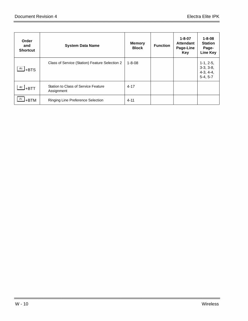
W - 10 Wireless
___________________________________________________________________________________
___________________________________________________________________________________Document Revision 4 Electra Elite IPK
+BTS
Class of Service (Station) Feature Selection 2 1-8-08 1-1, 2-5,3-3, 3-8, 4-3, 4-4, 5-4, 5-7
+BTTStation to Class of Service Feature Assignment
4-17
+BTM Ringing Line Preference Selection 4-11
Orderand
ShortcutSystem Data Name
Memory Block
Function
1-8-07AttendantPage-Line
Key
1-8-08StationPage-
Line Key

Features and Specifications Manual W - 11
___________________________________________________________________________________
___________________________________________________________________________________
Wireless – DECT W-2
FEATURE DESCRIPTION
The Wireless – DECT system allows the use of 2.4 GHz IPK Wireless – DECT (Digital Enhanced Cordless Telecommunication) telephones. These telephones provide the freedom and convenience of a wireless telephone but also allow access to features provided by the Electra Elite IPK system. A BSU(4M)-U20 ETU interfaces the Electra Elite IPK KSU with four Base Stations and can be expanded to 16 Base Stations with two BSU(6S)-U20 ETUs.
The Electra Elite IPK Expanded system supports 40 IPK Wireless – DECT telephones.
The Electra Elite IPK Basic system supports 24 IPK Wireless – DECT telephones.
Components of the IPK Wireless – DECT system include the following:
Handset
The handset has the following features:
Alphanumeric Display with Backlight
The backlight can be turned On/Off in the profile setup.
LED Indication for Incoming and Unanswered Calls
Telephone Book with 65 Number Memory Capacity
While idle, dial the number to be stored, then press > and OK. Enter the name associated with the number using the dial pad, and press OK.
Built-in Vibrator
The vibrator can be turned On/Off using the > and < keys in the profile setup.
Auto Log-in (auto switch between four systems)
The handset can be subscribed to 4 different systems. When Auto log-in is selected from the handset menu, the handset automatically selects the closest system. The selected system is marked with A.
Silent Mode (mute all sounds)
To set/cancel Silent Mode, press the Menu key and dial #.
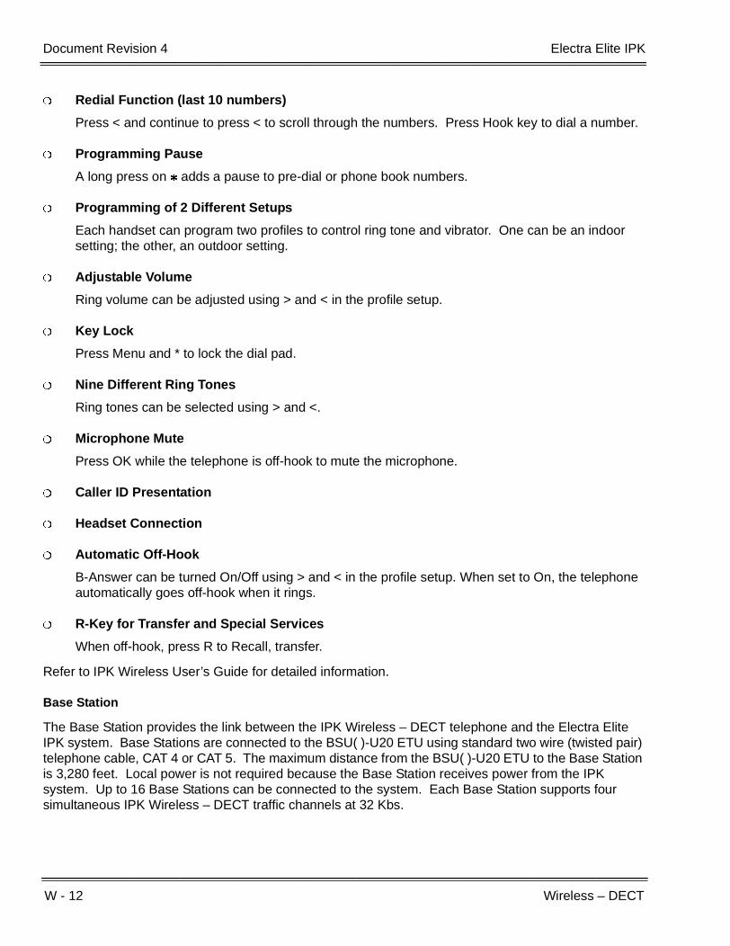
W - 12 Wireless – DECT
___________________________________________________________________________________
___________________________________________________________________________________Document Revision 4 Electra Elite IPK
Redial Function (last 10 numbers)
Press < and continue to press < to scroll through the numbers. Press Hook key to dial a number.
Programming Pause
A long press on adds a pause to pre-dial or phone book numbers.
Programming of 2 Different Setups
Each handset can program two profiles to control ring tone and vibrator. One can be an indoor setting; the other, an outdoor setting.
Adjustable Volume
Ring volume can be adjusted using > and < in the profile setup.
Key Lock
Press Menu and * to lock the dial pad.
Nine Different Ring Tones
Ring tones can be selected using > and <.
Microphone Mute
Press OK while the telephone is off-hook to mute the microphone.
Caller ID Presentation
Headset Connection
Automatic Off-Hook
B-Answer can be turned On/Off using > and < in the profile setup. When set to On, the telephone automatically goes off-hook when it rings.
R-Key for Transfer and Special Services
When off-hook, press R to Recall, transfer.
Refer to IPK Wireless User’s Guide for detailed information.
Base Station
The Base Station provides the link between the IPK Wireless – DECT telephone and the Electra Elite IPK system. Base Stations are connected to the BSU( )-U20 ETU using standard two wire (twisted pair) telephone cable, CAT 4 or CAT 5. The maximum distance from the BSU( )-U20 ETU to the Base Station is 3,280 feet. Local power is not required because the Base Station receives power from the IPK system. Up to 16 Base Stations can be connected to the system. Each Base Station supports four simultaneous IPK Wireless – DECT traffic channels at 32 Kbs.

Electra Elite IPK Document Revision 4
Features and Specifications Manual W - 13
___________________________________________________________________________________
___________________________________________________________________________________
Repeater
The Repeater allows extended coverage for low traffic areas not covered by a Base Station. Sufficient coverage for the main traffic area should be provided by the Base Station. An external antenna can also be connected to extend the coverage area. Local power is required for the Repeater (within 6 feet) and must be synchronized with a Base Station in the zone providing coverage. The Repeater is synchronized with the Base Station using the Repeater Programming Kit that provides an RS232 cable to connect the Repeater to a PC. A Windows application is used to define the Base Station that should be synchronized with the Repeater.
Each Repeater can support two simultaneous IPK Wireless – DECT traffic channels at 32 Kbs. As the Repeater is paired with the Base Station, these are not additional channels, but are available to handle calls from the Base Station as the user moves out of range from the Base Station to the Repeater area. Repeaters should be placed a minimum of 75 feet line of sight between each other to prevent problems with the channels in use.
SYSTEM AVAILABILITY
Terminal Type:
IPK Wireless – DECT Telephones
Required Components:
BSU(4M)-U20 ETU (Master)
BSU(2S)-U20 ETU (Slave)
BSU(6S)-U20 ETU (Slave)
Base Station (BS)
Administration Program (Windows Application) included with the BSU(4M)-U20 ETU.
Required Software:
R4000 or higher

W - 14 Wireless – DECT
___________________________________________________________________________________
___________________________________________________________________________________Document Revision 4 Electra Elite IPK
OPERATING PROCEDURES
Placing an Outside Call:
1. Press key (On/Off Hook).
2. Dial I.
3. Dial outside number
Placing an Outside Call with Pre-dial:
1. DialI.
2. Press and holdJto insert pause (-) if necessary
3. Dial the outside number.
4. Press key (On/Off Hook.
SERVICE CONDITIONS
General:
The CLKG-U( ) Unit is not required for IPK Wireless-DECT.
Four simultaneous calls can be made per Base Station.
Sixteen simultaneous calls can be made per BSU (Master or slave) ETU.
Thirty-Two simultaneous calls can be made per IPK system.
Two simultaneous calls can be made per Repeater.
Repeaters expand the coverage area of a Base Station without using a BSU port.
Each Base Station can have up to 12 Repeaters, but only three Repeaters can be used to form a linear line (chain).
When IPK Wireless – DECT telephone does not respond to an incoming call within 12 seconds because it is out of area or turned Off, the originator hears a busy tone and OUT OF AREA is displayed on the Multiline Terminal LCD.
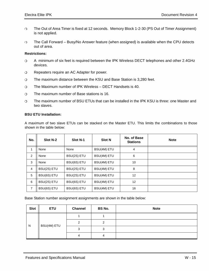
Electra Elite IPK Document Revision 4
Features and Specifications Manual W - 15
___________________________________________________________________________________
___________________________________________________________________________________
The Out of Area Timer is fixed at 12 seconds. Memory Block 1-2-30 (PS Out of Timer Assignment) is not applied.
The Call Forward – Busy/No Answer feature (when assigned) is available when the CPU detects out of area.
Restrictions:
A minimum of six feet is required between the IPK Wireless DECT telephones and other 2.4GHz devices.
Repeaters require an AC Adapter for power.
The maximum distance between the KSU and Base Station is 3,280 feet.
The Maximum number of IPK Wireless – DECT Handsets is 40.
The maximum number of Base stations is 16.
The maximum number of BSU ETUs that can be installed in the IPK KSU is three: one Master and two slaves.
BSU ETU Installation:
A maximum of two slave ETUs can be stacked on the Master ETU. This limits the combinations to thoseshown in the table below:
Base Station number assignment assignments are shown in the table below:
No. Slot N-2 Slot N-1 Slot NNo. of Base
StationsNote
1 None None BSU(4M) ETU 4
2 None BSU(2S) ETU BSU(4M) ETU 6
3 None BSU(6S) ETU BSU(4M) ETU 10
4 BSU(2S) ETU BSU(2S) ETU BSU(4M) ETU 8
5 BSU(6S) ETU BSU(2S) ETU BSU(4M) ETU 12
6 BSU(2S) ETU BSU(6S) ETU BSU(4M) ETU 12
7 BSU(6S) ETU BSU(6S) ETU BSU(4M) ETU 16
Slot ETU Channel BS No. Note
N BSU(4M) ETU
1 1
2 2
3 3
4 4
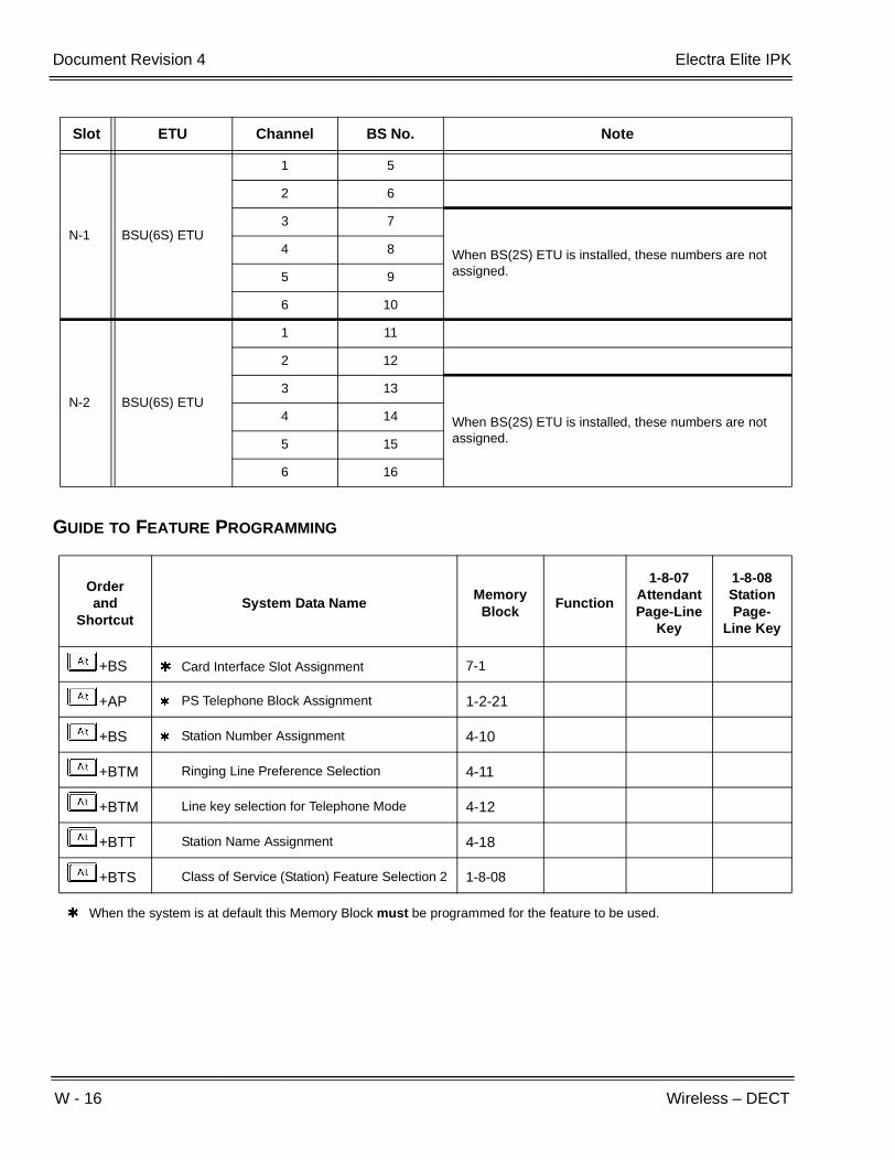
W - 16 Wireless – DECT
___________________________________________________________________________________
___________________________________________________________________________________Document Revision 4 Electra Elite IPK
GUIDE TO FEATURE PROGRAMMING
N-1 BSU(6S) ETU
1 5
2 6
3 7
When BS(2S) ETU is installed, these numbers are not assigned.
4 8
5 9
6 10
N-2 BSU(6S) ETU
1 11
2 12
3 13
When BS(2S) ETU is installed, these numbers are not assigned.
4 14
5 15
6 16
Orderand
ShortcutSystem Data Name
Memory Block
Function
1-8-07AttendantPage-Line
Key
1-8-08StationPage-
Line Key
+BS Card Interface Slot Assignment 7-1
+AP PS Telephone Block Assignment 1-2-21
+BS Station Number Assignment 4-10
+BTM Ringing Line Preference Selection 4-11
+BTM Line key selection for Telephone Mode 4-12
+BTT Station Name Assignment 4-18
+BTS Class of Service (Station) Feature Selection 2 1-8-08
When the system is at default this Memory Block must be programmed for the feature to be used.
Slot ETU Channel BS No. Note

Features and Specifications Manual 3 - 1
___________________________________________________________________________________
___________________________________________________________________________________
Feature Access Codes Chapter 3
SECTION 1 GENERAL INFORMATION
The table in this chapter shows the Access Codes used in the system. Some codes are set as system defaults. Others have no default, but are programmable.
Table notes include the following:
Installation
Access Codes operate on telephones specified during installation.
All other notes are self explanatory
Function Operation Notes
Microphone ON/OFF A Dial A
System Name Confirmation
A Dial C
Verify Station Number A Dial D
Confirm Timed Alarm A Dial EA A
Reset Timed Alarm System
A Dial EH A Installation
Reset Timed Alarm A Dial EI A
Set Do Not Disturb A Dial FK A
Set Call Forward – All Calls
A Dial FK Dial XXX A XXX = Station number where call is to be forwarded.
Set Automatic Trunk-to-Trunk Transfer Mode
A Dial FA Dial XX A XX = Incoming Trunk Port Number (01~64) 00 = All Trunks
Installation
Cancel Automatic Trunk-to-Trunk Transfer to Outside Mode
A Dial FB Dial XX A XX = Incoming Trunk Port Number (01~64) 00 = All Trunks
Installation

3 - 2 Feature Access Codes
___________________________________________________________________________________
___________________________________________________________________________________Document Revision 4 Electra Elite IPK
Set Automatic Trunk-to-Trunk Transfer Outgoing Trunk
A Dial FC Dial XX Dial L Dial YY~Y A XX = Incoming Trunk Port Number (01~64) 00 = All TrunksYY~Y = Transfer Telephone Number (Max 24 Digits)
Installation
Confirm Transfer Number for Automatic Trunk-to-Trunk Transfer
A Dial FD Dial XX A XX = Trunk Port Number (01~64)
Installation
Serial Port Verification
A Dial FE XXXX = PYY/SZZ is displayedXXXX = Extension NumberYY = Physical Port NumberZZ = Serial Port Number Moves back one extension and # moves up one extension.
Used to find the Serial
Port number for Electra Stat.
Cancel Call Forward – All Calls by System
A Dial FH A Installation
Cancel Do Not Disturb/Call Forward – All Calls
A Dial FI A Installation
Set Customized Message Display
A Dial GK Dial J Dial L
[Dial XX:XX, YY:YY] A J Selects displayL Sets DisplayXX:XX = Date of ReturnYY:YY = Time of ReturnOptional Operations are enclosed in [ ]
Cancel Customized Message Display by System
A Dial GH A Installation
Cancel Customized Message Display
A Dial GI A
Set/Cancel Night Mode Switch (System)
A Dial HK A InstallationAttendant Only
Set Automated Attendant/DISA Mode
A Dial HA Dial XX A XX = Incoming Trunk Port Number (01~64) 00 = All Trunks
Installation
Function Operation Notes
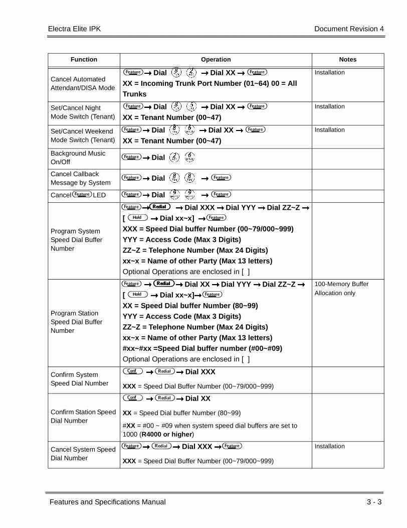
Electra Elite IPK Document Revision 4
Features and Specifications Manual 3 - 3
___________________________________________________________________________________
___________________________________________________________________________________
Cancel Automated Attendant/DISA Mode
A Dial HB Dial XX A XX = Incoming Trunk Port Number (01~64) 00 = All Trunks
Installation
Set/Cancel Night Mode Switch (Tenant)
A Dial HE Dial XX A XX = Tenant Number (00~47)
Installation
Set/Cancel Weekend Mode Switch (Tenant)
A Dial HF Dial XX A XX = Tenant Number (00~47)
Installation
Background Music On/Off
A Dial BF
Cancel Callback Message by System
A Dial HH A
Cancel A LED A Dial II A
Program System Speed Dial Buffer Number
A B Dial XXX Dial YYY Dial ZZ~Z [ H Dial xx~x] A XXX = Speed Dial buffer Number (00~79/000~999)YYY = Access Code (Max 3 Digits)ZZ~Z = Telephone Number (Max 24 Digits)xx~x = Name of other Party (Max 13 letters)Optional Operations are enclosed in [ ]
Program Station Speed Dial Buffer Number
A B Dial XX Dial YYY Dial ZZ~Z [ H Dial xx~x] A XX = Speed Dial buffer Number (80~99)YYY = Access Code (Max 3 Digits)ZZ~Z = Telephone Number (Max 24 Digits)xx~x = Name of other Party (Max 13 letters)#xx~#xx =Speed Dial buffer number (#00~#09)Optional Operations are enclosed in [ ]
100-Memory Buffer
Allocation only
Confirm System Speed Dial Number
D B Dial XXX
XXX = Speed Dial Buffer Number (00~79/000~999)
Confirm Station Speed Dial Number
D B Dial XX
XX = Speed Dial buffer Number (80~99)
#XX = #00 ~ #09 when system speed dial buffers are set to 1000 (R4000 or higher)
Cancel System Speed Dial Number
A B Dial XXX A
XXX = Speed Dial Buffer Number (00~79/000~999)
Installation
Function Operation Notes
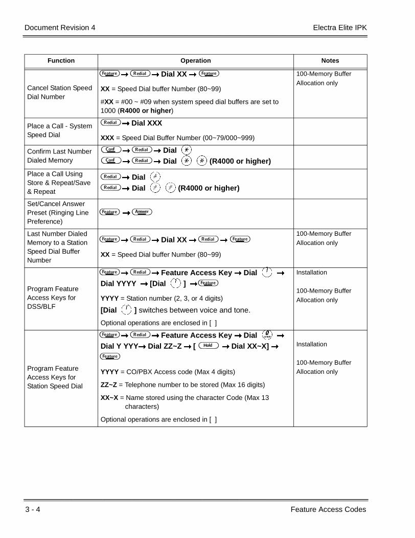
3 - 4 Feature Access Codes
___________________________________________________________________________________
___________________________________________________________________________________Document Revision 4 Electra Elite IPK
Cancel Station Speed Dial Number
A B Dial XX A
XX = Speed Dial buffer Number (80~99)
#XX = #00 ~ #09 when system speed dial buffers are set to 1000 (R4000 or higher)
100-Memory Buffer
Allocation only
Place a Call - System Speed Dial
B Dial XXX
XXX = Speed Dial Buffer Number (00~79/000~999)
Confirm Last Number Dialed Memory
D B Dial J D B Dial JJ(R4000 or higher)
Place a Call Using Store & Repeat/Save & Repeat
B Dial L B Dial LL(R4000 or higher)
Set/Cancel Answer Preset (Ringing Line Preference)
A F
Last Number Dialed Memory to a Station Speed Dial Buffer Number
A B Dial XX B A
XX = Speed Dial buffer Number (80~99)
100-Memory Buffer
Allocation only
Program Feature Access Keys for DSS/BLF
A B Feature Access Key Dial A Dial YYYY [Dial A] A
YYYY = Station number (2, 3, or 4 digits)
[Dial A] switches between voice and tone.
Optional operations are enclosed in [ ]
Installation
100-Memory Buffer
Allocation only
Program Feature Access Keys for Station Speed Dial
A B Feature Access Key Dial K
Dial Y YYY Dial ZZ~Z [ H Dial XX~X] A
YYYY = CO/PBX Access code (Max 4 digits)
ZZ~Z = Telephone number to be stored (Max 16 digits)
XX~X = Name stored using the character Code (Max 13 characters)
Optional operations are enclosed in [ ]
Installation
100-Memory Buffer Allocation only
Function Operation Notes
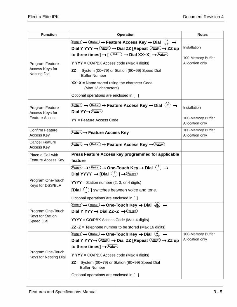
Electra Elite IPK Document Revision 4
Features and Specifications Manual 3 - 5
___________________________________________________________________________________
___________________________________________________________________________________
Program Feature Access Keys for Nesting Dial
A B Feature Access Key Dial K
Dial Y YYY F Dial ZZ [Repeat F ZZ up to three times] [ H Dial XX~X] A
Y YYY = CO/PBX Access code (Max 4 digits)
ZZ = System (00~79) or Station (80~99) Speed Dial Buffer Number
XX~X = Name stored using the character Code (Max 13 characters)
Optional operations are enclosed in [ ]
Installation
100-Memory Buffer Allocation only
Program Feature Access Keys for Feature Access
A B Feature Access Key Dial L
Dial YY A
YY = Feature Access Code
Installation
100-Memory Buffer Allocation only
Confirm Feature Access Key
A Feature Access Key100-Memory Buffer Allocation only
Cancel Feature Access Key
A B Feature Access Key A
Place a Call with Feature Access Key
Press Feature Access key programmed for applicable feature.
Program One-Touch Keys for DSS/BLF
A B One-Touch Key Dial A Dial YYYY [Dial A] A
YYYY = Station number (2, 3, or 4 digits)
[Dial A] switches between voice and tone.
Optional operations are enclosed in [ ]
Program One-Touch Keys for Station Speed Dial
A B One-Touch Key Dial K
Dial Y YYY Dial ZZ~Z A
YYYY = CO/PBX Access Code (Max 4 digits)
ZZ~Z = Telephone number to be stored (Max 16 digits)
Program One-Touch Keys for Nesting Dial
A B One-Touch Key Dial K
Dial Y YYY F Dial ZZ [Repeat F ZZ up to three times] A
Y YYY = CO/PBX Access code (Max 4 digits)
ZZ = System (00~79) or Station (80~99) Speed Dial Buffer Number
Optional operations are enclosed in [ ]
100-Memory Buffer Allocation only
Function Operation Notes

3 - 6 Feature Access Codes
___________________________________________________________________________________
___________________________________________________________________________________Document Revision 4 Electra Elite IPK
Program One-Touch Keys for Feature Access
A B One-Touch Key Dial L
Dial YY A
YY = Feature Access Code
Confirm One-Touch Key
A One-Touch Key ( A only if arrow is displayed).
Cancel One-Touch Key
A B One-Touch Key A
Place a call with One-Touch Key
Press the One-Touch key programmed for the desired feature.
Function Operation Notes

FEATURES AND SPECIFICATIONS MANUAL
NEC Unified Solutions, Inc.
Document Revision 4
(Release 4000/4500)
