elbow meters for on-farm irrigation water measurement meter report 2007.pdf · elbow meters for...
TRANSCRIPT
ELBOW METERS FOR ON-FARM
IRRIGATION WATER MEASUREMENT
Prepared by: G. Guy, P. Eng. & R. Powley, P. Eng. AAFC-PFRA Water Supply Technology Unit
T. Helwig, P. Eng. AAFRD Irrigation Branch
June, 2007

AAFC-PFRA/AAFRD Elbow Meter Study
TABLE OF CONTENTS
Introduction............................................................................................................................ 1 Rationale ................................................................................................................................ 1 Objective ................................................................................................................................ 1 Test Set-Up............................................................................................................................. 1 Metering Equipment .............................................................................................................. 4
ID Tech EFC1000 Electronic Flow Calculator...................................................................... 4 Blue White F1000 Paddle Meter .......................................................................................... 5 Fabricated U-Tube Manometer ............................................................................................ 5
Data Collection ...................................................................................................................... 7 Results and Discussion ........................................................................................................ 7
ID Tech EFC1000 Electronic Flow Calculator...................................................................... 7 Blue White F1000 Paddle Meter .......................................................................................... 9 Inverted U-Tube Manometer.............................................................................................. 10
Summary .............................................................................................................................. 11
i
AAFC-PFRA/AAFRD Elbow Meter Study
1
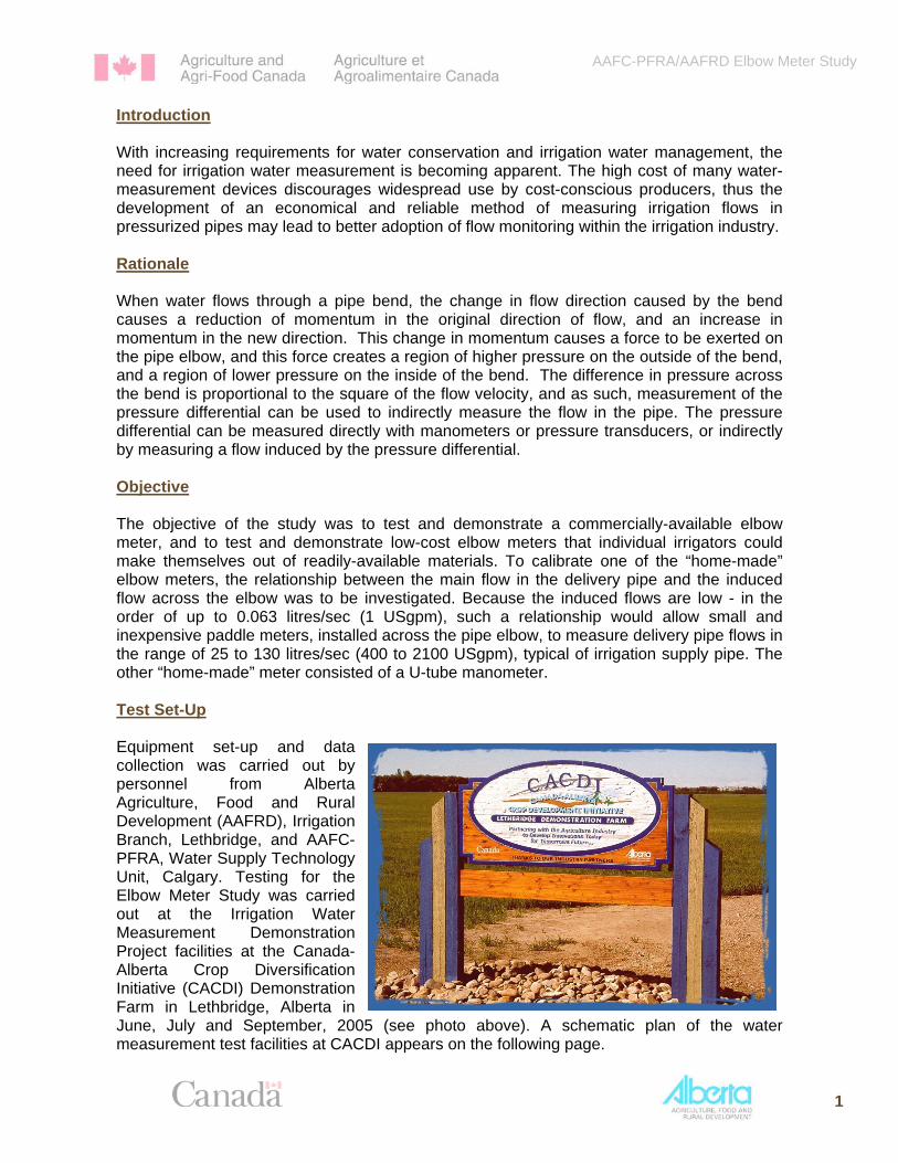
Introduction With increasing requirements for water conservation and irrigation water management, the need for irrigation water measurement is becoming apparent. The high cost of many water-measurement devices discourages widespread use by cost-conscious producers, thus the development of an economical and reliable method of measuring irrigation flows in pressurized pipes may lead to better adoption of flow monitoring within the irrigation industry. Rationale When water flows through a pipe bend, the change in flow direction caused by the bend causes a reduction of momentum in the original direction of flow, and an increase in momentum in the new direction. This change in momentum causes a force to be exerted on the pipe elbow, and this force creates a region of higher pressure on the outside of the bend, and a region of lower pressure on the inside of the bend. The difference in pressure across the bend is proportional to the square of the flow velocity, and as such, measurement of the pressure differential can be used to indirectly measure the flow in the pipe. The pressure differential can be measured directly with manometers or pressure transducers, or indirectly by measuring a flow induced by the pressure differential. Objective The objective of the study was to test and demonstrate a commercially-available elbow meter, and to test and demonstrate low-cost elbow meters that individual irrigators could make themselves out of readily-available materials. To calibrate one of the “home-made” elbow meters, the relationship between the main flow in the delivery pipe and the induced flow across the elbow was to be investigated. Because the induced flows are low - in the order of up to 0.063 litres/sec (1 USgpm), such a relationship would allow small and inexpensive paddle meters, installed across the pipe elbow, to measure delivery pipe flows in the range of 25 to 130 litres/sec (400 to 2100 USgpm), typical of irrigation supply pipe. The other “home-made” meter consisted of a U-tube manometer. Test Set-Up Equipment set-up and data collection was carried out by personnel from Alberta Agriculture, Food and Rural Development (AAFRD), Irrigation Branch, Lethbridge, and AAFC-PFRA, Water Supply Technology Unit, Calgary. Testing for the Elbow Meter Study was carried out at the Irrigation Water Measurement Demonstration Project facilities at the Canada-Alberta Crop Diversification Initiative (CACDI) Demonstration Farm in Lethbridge, Alberta in June, July and September, 2005 (see photo above). A schematic plan of the water measurement test facilities at CACDI appears on the following page.

AAFC-PFRA/AAFRD Elbow Meter Study
2
Stilling well
Above-groundeline metering
reach pip
test
Open meteringvault
By-passriser #1
Magmeter
Pump
Digi-flowmeter
Armtec Ltd. overshot &slide control gates
Contracted rectangularweir
Turnout
Cipoletti weir
AquaSystems 2000 Ltd.Langemann gate/turnout
Broad-crested weir
V-notch weir
Turnout
Sup
ply
Pip
elin
e
Circular flume
Late
ral P
ipel
ine
Can
al
Canal liningdemonstration
Boardwalk
Pond
Horiba SDI multi-probe & ISCO water sampler (Avensys), ROM Communications
PondWetland
N
Schematic Plan - Irrigation Water Measurement Demonstration Project
Above-ground metering test
reach
Magmeter
Pump
Canada-Alberta Crop Diversification Initiative (CACDI) Lethbridge Demonstration Farm

AAFC-PFRA/AAFRD Elbow Meter Study
Water supply for the test procedure was provided by an existing turbine pump at the demonstration site (see schematic on previous page). Reference flow measurement was provided by an existing in-line, electromagnetic flow meter (Badger “Magnetoflo”)1 located about 30m upstream of the pipeline test section. Flow to the pipeline meter testing section was controlled by butterfly valves in concrete vaults at the upstream and downstream ends of the section. Riser pipes installed in the concrete vaults allowed connection of various diameters of surface piping and associated elbows and measurement equipment. Surface piping consisted of portable 150mm, 200mm and 250mm irrigation pipe and elbows. The following figure is a schematic representation of the test layout:
1 http://www.badgermeter.com/magflowb.htm
3

AAFC-PFRA/AAFRD Elbow Meter Study
4
Two configurations of 90 degree elbows - a short-radius sweep elbow and a mitred elbow, were examined for the study. For each configuration, two elbows were fabricated, in diameters of 150mm (6”), 200mm (8”), and 250mm (10”). Each elbow was fitted with 3“ dia. (commercial elbow meter and U-tube manometer) or ⅜” dia. (for the paddle-meter elbow meter) FPT pressure ports at the outside and inside of the bends, as shown in the following photos.
Having two identical elbows allowed simultaneous testing of a commercially-available elbow meter on one elbow and a paddlewheel flow meter (measuring induced flow) on the other elbow. The U-tube manometer was connected to the same elbow as the commercially-available elbow meter. Metering Equipment As stated previously, three different types of elbow meters were tested for this study: a commercially-available elbow meter (ID Tech EFC 1000 Electronic Flow Calculator2), a home-made elbow meter created by connecting a paddle meter (Blue White F10003) across an elbow to measure the induced flow, and a fabricated U-tube manometer. This section provides a brief description of the three devices.
ID Tech EFC1000 Electronic Flow Calculator The ID Tech EFC1000 measures differential pressure between the inside and outside bends of a pipe elbow using a pressure transducer, and converts the electrical signal from the transducer into flow rates based on proprietary empirical data established by the meter manufacturer. The meter can also display the differential pressure measured by the transducer. The meter is initialized by inputting physical data such as pipe elbow diameter and geometry. Input and read-out functions are on the front face of the meter. Operators can scroll through the meter’s panel display to review the data input.
2 http://www.valveandfilter.com/idtechflowmeters.htm 3 http://blue-white.com/Products/ElectronicFlow/F-1000RB/digiflo_product.asp
Sweep Mitre

AAFC-PFRA/AAFRD Elbow Meter Study
Output data is displayed in real time, and includes flow rate, total flow, and differential pressure. Either imperial or metric units may be selected. Manufacturer’s literature indicates that these meters can be used on mitred or sweep elbows with deflections between 25 and 90 degrees, within a range of internal diameters between 4” and 24” (100 mm – 610 mm). Measurement accuracy is stated to be ±2%. Blue White F1000 Paddle Meter Paddlewheel flow meters consist of three primary components; the pipe fitting, the paddlewheel sensor, and the display/controller. These components can be purchased separately or as a package to meet the
particular requirements of the application. The paddlewheel sensor is designed to be inserted into the pipe fitting. Approximately one half of the paddle protrudes into the flow stream. Fluid flowing through the pipe causes the paddlewheel to spin. As the magnets that are embedded in the paddle spin past the sensor,
electrical pulses are produced that are proportional to the rate of flow. The number of output pulses produced, per volume of flow, for each specific pipe fitting are correlated with an integrated sensor and display. The full-scale rate range for the meter used in this study (RT375MILPM2) is stated by the manufacturer to be 0.4 – 4.0 USgpm (1.0 - 10.0 lpm). According to the manufacturer’s literature, readings within that range should have an accuracy of ±2%. Fabricated U-Tube Manometer Based on a design described in a United States Bureau of Reclamation publication4, an inverted U-tube manometer was constructed out of readily-available materials. The manometer was used to measure pressure differentials across the pipe elbows. Using the valves incorporated into the manometer, air was bled off until no bubbles were visible in the manometer tubes. Once all the air had been evacuated, the valves were closed, and air was pumped into the top of the manometer with a bicycle tire pump through a Schrader valve installed at the top, until a free water surface was observed within each tube comprising the manometer. The image at the right illustrates the manometer, and the images on the following page are close-ups of the fittings that comprise the upper and lower ends of the device.
Plywood mounting board
¼ “ X 4’ Clear Vinyl Tubing With Tape Affixed to Mounting Board to Measure Water Levels in Tubing
4 http://www.usbr.gov/pmts/hydraulics_lab/pubs/OM/OM-207.pdf
¼ “Clear Vinyl Tubing Connecting Manometer to
Pressure Taps on Pipe Elbow
5

AAFC-PFRA/AAFRD Elbow Meter Study
¼ “ Male NPT Schrader Air Valve
¼ “ Clear Vinyl Tubing Connecting Manometer to Pressure Taps on Pipe Elbow
1/8” OD X 1/16” ID X 69” long 2½ “ ∅ Coil
¼ “ Male NPT X ¼ “ barb, straight
¼ “ Female NPT X ¼ “ Female NPT Needle Valve
¼ “ Female NPT Tee
1/8“ Male NPT to 1/8“ Compression and ¼ “
to 1/8” reducer bushing
¼ “ Male NPT X ¼ “ Barb, Elbow
¼ “ Female NPT Tee
¼ “ X 4’ Clear Vinyl Tubing With Tape Affixed to Mounting Board to Measure Water Levels in Tubing
¼ “ Female NPT X ¼ “ Female NPT Needle Valve
¼ “ Male NPT X ¼ “ barb, elbow
¼ “ Female NPT Cross
¼ “ Male NPT X ¼ “ barb, straight
Differential Water Levels Observed
6

AAFC-PFRA/AAFRD Elbow Meter Study
Data Collection Flows were monitored in aluminium irrigation pipe of 150mm, 200mm and 250mm nominal diameter, at the above-ground meter test facility. For each diameter, one test was run with the sweep elbows installed, and another with the mitred elbows. A team of two to three persons were on hand to assemble and disassemble the pipes and elbows and perform the measurements. Reducer fittings were used to stub down from the 250mm (10”) dia. riser pipes in the meter vaults as required. For each test, the ID Tech EFC1000 was initialized to reflect the particular pipe diameter and elbow geometry. The ID Tech EFC1000 elbow meter, the F1000 paddle meter (flow meter), and the U-tube manometer were connected via vinyl tubing to identical elbows via the pressure ports on each elbow. The pump was started and the flow rate was controlled via a butterfly valve on the discharge
side of the pump at the pumphouse. The desired flow rate was confirmed at the magmeter vault located 30 m upstream of elbow meter testing apparatus. At a given signal, the data collection team would collect the following data: from the magmeter: time, flow rate and cumulative flow; from the ID Tech EFC 1000: time, flow rate, pressure differential and cumulative flow; from the F1000 paddle meter: time and flow rate, and from the U-tube manometer, water levels in each side. The butterfly valve at the pump would then be adjusted, a new flow rate established, and a new series of data collected.
Results and Discussion
ID Tech EFC1000 Electronic Flow Calculator Flow measurements obtained with the EFC1000 were plotted against those obtained from the reference electromagnetic flow meter. The following figures illustrate the performance of the EFC1000 relative to the mag meter:
Comparison of EFC1000 with Mag Meter 6" dia. Sweep & Mitered Bends
0.00
10.00
20.00
30.00
40.00
50.00
60.00
70.00
80.00
0 10 20 30 40 50 60 70 80
Reference (Mag Meter) Discharge(L/s)
Dis
char
ge M
easu
red
with
EFC
1000
(L/s
)
6" Mitred
6" Sweep
5%
10%
7

AAFC-PFRA/AAFRD Elbow Meter Study
Comparison of EFC1000 with Mag Meter 8" dia. Sweep & Mitered Bends
0.00
20.00
40.00
60.00
80.00
100.00
120.00
0 20 40 60 80 100 12
Reference (Mag Meter) Discharge(L/s)
Dis
char
ge M
easu
red
with
EFC
1000
(L/s
)
0
8" Mitred
8" Sweep
5%
10%
Comparison of EFC1000 with Mag Meter 10" dia. Sweep & Mitered Bends
0
20
40
60
80
100
120
140
0 20 40 60 80 100 120 140
Reference (Mag Meter) Discharge(L/s)
Dis
char
ge M
easu
red
with
EFC
1000
(L/s
)
10" Mitred
10" Sweep
5%
10%
As can be seen from these plots, the data obtained from the EFC1000 is generally within 5% to 10% of the reference flows measured with the electromagnetic flow meter. Significant differences were observed at the upper and lower ends of the measured ranges, and this is consistent with observations from other research. At the lower end of the flow spectrum, velocities in the pipe are relatively low, and hence the differential pressures across the bend are correspondingly low and difficult to measure with any accuracy. At the upper end of the spectrum, the pressure differential is likely higher than the upper limit for the transducer. Nevertheless, agreement is remarkably good for those flows within a reasonable range for each pipe size, especially considering the fact that the configurations tested differed slightly from those recommended by the manufacturer. For the mitred bends, the manufacturer recommends that the pressure taps be located as shown below:
8
PressureTaps

AAFC-PFRA/AAFRD Elbow Meter Study
This differs somewhat from the configuration used for this study (shown to the right), and it is not unreasonable to expect the results from the EFC1000 be less “accurate” for a situation that differs from that for which it was calibrated. For the sweep bends, the EFC1000 was calibrated for bends having slightly different radii than those used in this study. For the 6” (15 cm) sweep bend, the outside radius (22.6 cm) of the bend used was within the range of values allowed by the EFC1000, but the inside radius was slightly tighter than that for which the EFC1000 was calibrated (6.05 cm as opposed to 7.47 cm). This is a relatively small difference, and agreement with the flows measured with the mag meter was correspondingly close. For the 8” (20 cm) sweep bend, the outside radius of the bend used (22.6 cm) was less than the minimum allowed by the EFC1000 (30.02 cm), and the inside radius was also slightly tighter than that for which the EFC1000 was calibrated (6.37 cm as opposed to 10.08 cm). As a result, agreement between flows measured with the EFC1000 and the mag meter was somewhat poorer.
Standard Construction Used for Mitre Test
Blue White F1000 Paddle Meter Measurements of the induced flow across the bends obtained with the Blue White F1000 Paddle Meter were plotted against main pipe flows obtained from the reference electromagnetic flow meter. The following figures illustrate the relationship between the two flows for the various pipe sizes and bend configurations:
Relationship Between Main Pipe Discharge and FL1000 Discharge
6 inch
8 inch
10 inch
Q = 1560.4q + 1260.3
Q = 1565.5q + 818.2
Q = 2961.8q + 1307.5Q = 2574.6q + 1901.6
Q = 3357.3q + 3772.4
Q = 3668.1q + 2877.7
0
1000
2000
3000
4000
5000
6000
7000
8000
9000
0.00 0.50 1.00 1.50 2.00 2.50
FL1000 Discharge - q(L/min)
Mai
n Pi
pe D
isch
arge
- Q
(L
/min
)
Sweep
Mitred
9

AAFC-PFRA/AAFRD Elbow Meter Study
These results are fairly self-explanatory – there is, and should be, a linear relationship between the main pipe discharge and the discharge induced across the elbow5. However, it is, in a strict sense, only valid for the configuration and equipment tested. A setup with different lengths of tubing connecting the bypass flow meter to the main pipe, and/or a different brand of meter, would have a different relationship because the energy losses in the bypass route due to the meter and friction in the connecting hose would be different. Inverted U-Tube Manometer The following plot illustrates the relationship between measured flows and pressure differentials across the elbows as measured using the fabricated inverted U-tube manometer.
Discharge vs. Differential Head in Irrigation Pipe Elbows
10 inch
8 inch
6 inch
Q = 55.15ΔH0.511
Q = 57.96ΔH0.504
Q = 89.81ΔH0.510
Q = 96.04ΔH0.500
Q = 149.70ΔH0.549
Q = 139.60ΔH0.501
0
20
40
60
80
100
120
140
0 0.1 0.2 0.3 0.4 0.5 0.6 0.7 0.8 0.9 1
Differential Head - ΔH (m)
Dis
char
ge -
Q (L
/s)
Sweep
Mitered
The USBR publication cited in footnote 4 proposes the following relationship that describes the correlation between the flow through the elbow and the differential pressure across it: EHMQ Δ= Where Q is the discharge, ΔH is the head differential across the elbow, and M and E are calibration coefficients dependent on the elbow geometry. Early research and theoretical analyses indicated that the value of E should be 0.5, but it has been demonstrated that while close to 0.5, the value of E actually varies as a calibration parameter. The USBR study found that for a 90 degree mitred 8-inch aluminum elbow, the values of M and E were 92.8 and 0.500, respectively, which compares favourably to the values of 96.04 and 0.500 obtained from this study.
10
5 Yuan, B. Z., S. Nishiyama, M. Fukada and H. Kanamori, 2003, Hydraulic Design Procedure for Bypass Flow Meters Using a Pipe Bend, Transactions of the ASAE, Vol. 46(2), pp. 279-285

AAFC-PFRA/AAFRD Elbow Meter Study
Summary This study has shown that elbow meters are a viable method for measuring flows in typical on-farm irrigation systems. While elbow meters have a limited range, especially for low flows, this is unlikely to be a significant constraint to their utility in measuring flows in irrigation pipelines. Typically, on-farm irrigation systems only operate in an “on” or “off” mode, and they are usually designed to operate within the range of applicability for elbow meters. One advantage associated with elbow meters is their relatively low cost. The EFC1000 used in this study cost about $1,230 (taxes included), whereas the Blue White F1000 cost about $460, and the inverted U-tube manometer was assembled from materials that cost less than $100. The least costly, and most common, type of meter typically used in irrigation applications (an insertion-type propeller meter, shown to the right) has a price similar to the EFC1000 for 6” and 8’” pipe, but would be considerably more expensive for larger pipe sizes. The EFC1000 can be used on any pipe size up to 24” (610 mm). The Blue White F1000 and the U-tube manometer could also be used on larger pipes if they were calibrated for those pipe sizes.
Propeller Meter Installed in Pipe
Prop
elle
r Met
er
Another advantage elbow meters have over more common flow-measurement devices is that they can be installed in relatively confined spaces6, and they do not obstruct the flow in any way7. As such, they are less susceptible to being fouled with weeds and debris that may be present in the water. This is particularly true of the EFC1000 and the inverted U-tube manometer, since there is no net flow through the meter at all. While an elbow meter constructed using a paddle meter installed across the elbow could potentially suffer from clogging with weeds and debris, it can easily be removed and serviced without interruption of the operation. Portability is another advantage associated with elbow meters8. Any elbow within the system that is fitted with valve-controlled pressure taps can be used as a flow measurement device, and as such, the same meter could be used to measure flows at a number of locations. While elbow meters may not be as accurate as other flow-measurement devices, their accuracy is more than adequate for most applications – it is certainly better than no measurement at all, a situation that is currently the norm. As mentioned earlier, the accuracy of the discharge readings obtained from the EFC1000 were somewhat compromised in this study because the fittings used differed slightly from situations that were used to calibrate the meter.
6 All meters that measure flow in pipelines require straight lengths of pipe upstream and downstream of the meter to ensure that the approach flow is uniform. For conventional flow meters, such as the propeller meter, required straight pipe lengths are 10 pipe diameters upstream and 5 pipe diameters downstream of the meter. For elbow meters, the straight length requirements are 5 pipe diameters upstream and two pipe diameters downstream of the meter. 7 Electromagnetic and ultrasonic flow meters also possess this attribute, but they are considerably more costly. They are, however, very accurate flow-measurement devices.
11
8 Strap-on ultrasonic doppler meters are also portable, can be used on a wide variety of pipe sizes, and are probably more accurate than elbow meters. They are, however, much more costly, and they require that the fluid being conveyed contain solids or bubbles to reflect the ultrasonic signal.

AAFC-PFRA/AAFRD Elbow Meter Study
It is very likely that the EFC1000 device could achieve accuracy close to the manufacturer’s stated values (±2%) as long as the elbow in question is consistent with configurations used in the calibration of the meter. Elbow meters constructed using a paddle-type flow meter installed across the elbow should produce fairly accurate results using the relationships presented in the preceding plots of induced flow versus main pipeline flow, as long as the elbow configurations are similar, and as long as the meter and its connection materials9 have similar energy-loss characteristics. Elbow meters that utilize a U-tube manometer for measuring pressure differential should produce fairly accurate results using the relationships presented in the preceding plots, as long as the elbow configurations are similar. Note that it is important that the U-tube manometer be level, as any tilt will accentuate the difference in water levels in the two tubes. For any elbow meter, it would be beneficial if the elbow where the meter is installed is surrounded by a cattle guard or similar enclosure to ensure that the hoses connecting the meter to the pressure taps on the elbow are not damaged by cattle or the movement of equipment. It would also be beneficial if the EFC1000 could incorporate a solar panel and associated circuitry to ensure that the battery that powers the unit maintains its charge. Another useful feature that should be included with the documentation for the EFC1000 would be a list of dimensions that describe the calibration range for the instrument, so that the user can ensure that they order elbows that are consistent with the calibration limits of the meter.
12
9 The F1000 paddle meter was connected to the pressure taps on the main pipeline elbow with 1.5 m lengths of clear vinyl tubing having an internal diameter of ¼ “ (6 mm) and an external diameter of ⅜ “ (9.5 mm).