effects of cutting parameter on machining …eprints.utem.edu.my/11463/1/cdr_09067-24_pages.pdf ·...
TRANSCRIPT
EFFECTS OF CUTTING PARAMETER ON MACHINING
PERFORMANCE FOR WOOD-PLASTIC COMPOSITE
MATERIAL
MUHAMMAD FAIZH BIN SAZALI
B050910154
UNIVERSITI TEKNIKAL MALAYSIA MELAKA
2013
UNIVERSITI TEKNIKAL MALAYSIA MELAKA
EFFECTS OF CUTTING PARAMETER ON MACHINING
PERFORMANCE FOR WOOD-PLASTIC COMPOSITE MATERIAL
This report submitted in accordance with requirement of the Universiti Teknikal Malaysia
Melaka (UTeM) for the Bachelor Degree of Manufacturing Engineering
(Manufacturing Process) (Hons.)
by
MUHAMMAD FAIZH BIN SAZALI
B050910154
860717 – 59 - 5049
FACULTY OF MANUFACTURING ENGINEERING
2013
UNIVERSITI TEKNIKAL MALAYSIA MELAKA
BORANG PENGESAHAN STATUS LAPORAN PROJEK SARJANA MUDA
TAJUK: Investigate Surface Integrity When Machining FC300 Cast Iron Using
Uncoated Carbide Ball End Mill: Study Of Surface Profile
SESI PENGAJIAN: 2012/13 Semester 1
Saya MUHAMMAD FAIZH BIN SAZALI
mengaku membenarkan Laporan PSM ini disimpan di Perpustakaan Universiti
Teknikal Malaysia Melaka (UTeM) dengan syarat-syarat kegunaan seperti berikut:
1. Laporan PSM adalah hak milik Universiti Teknikal Malaysia Melaka dan penulis. 2. Perpustakaan Universiti Teknikal Malaysia Melaka dibenarkan membuat salinan
untuk tujuan pengajian sahaja dengan izin penulis. 3. Perpustakaan dibenarkan membuat salinan laporan PSM ini sebagai bahan
pertukaran antara institusi pengajian tinggi. 4. **Sila tandakan (√)
SULIT
TERHAD
TIDAK TERHAD
(Mengandungi maklumat yang berdarjah keselamatan atau
kepentingan Malaysia sebagaimana yang termaktub dalam
AKTA RAHSIA RASMI 1972)
(Mengandungi maklumat TERHAD yang telah ditentukan oleh
organisasi/badan di mana penyelidikan dijalankan)
Alamat Tetap:
No 5 Jln Rambutan Tmn Maju,
Parit Raja,
86400 Batu Pahat, JOHOR.
Tarikh: _________________________
Disahkan oleh:
Cop Rasmi:
Tarikh: _______________________
** Jika Laporan PSM ini SULIT atau TERHAD, sila lampirkan surat daripada pihak berkuasa/organisasi
berkenaan dengan menyatakan sekali sebab dan tempoh laporan PSM ini perlu dikelaskan sebagai
SULIT atau TERHAD.

DECLARATION
I hereby, declared this report entitled “Investigating Cutting Parameter For Wood Plastic
Composite” is the results of my own research except as cited in references.
Signature :
Author’s Name : Muhammad Faizh Bin Sazali
Date : 3 June 2013

APPROVAL
This report is submitted to the Faculty of Manufacturing Engineering of UTeM as a partial
fulfillment of the requirements for the degree of Bachelor of Manufacturing Engineering
(Manufacturing Process) (Hons.). The member of the supervisory committee is as follow:
………………………………
i
ABSTRACT
Wood-plastic composite (WPC) is a very promising and sustainable green material to
achieve durability without using toxic chemical. The term WPCs refers to any
composites that contain plant fiber and thermosets or thermoplastics. In comparison to
other fibrous materials, plant fibers are in general suitable to reinforce plastics due to
relative high strength and stiffness, low cost, low density, low CO2 emission,
biodegradability and annually renewable. Plant fibers as fillers and reinforcements for
polymers are currently the fastest-growing type of polymer additives. One of the most
important advantages of wood is its easy machinability in contrast to metal and plastic
products. However its non-uniform characteristic resulting from the combination with
polymer plays a significant role on its efficient and effective machining. Any surface
defects due to improper machining process will reduce the quality of the final products
resulting in increase in the cost of the manufactured unit. Therefore it is important to
evaluate the machining parameters and relate them with the fiber characteristics and
compositions. Thus, this study aims to study the effect of cutting parameters namely
spindle speed, feed rate and depth of cut on machining performance of WPC with
different composition. Statistical Respone Surface Methodology techniques were used
to evaluate the effect of cutting parameters on machining performance. Lastly, the
optimal cutting parameter for machining WPC is proposed.
ii
ABSTRAK
Komposit kayu-plastik (WPC) adalah bahan hijau yang sangat menjanjikan dalam
mencapai ketahanan tanpa menggunakan bahan kimia toksik. WPC adalah merujuk
kepada mana-mana komposit yang mengandungi serat tumbuhan dan termoset atau
termoset. Berbanding dengan bahan-bahan serat lain, serat tumbuh-tumbuhan adalah
secara umum di antara yang sesuai untuk mengukuhkan plastik kerana kekuatan relatif
tinggi dan ketegangan, kos yang rendah, kepadatan yang rendah, kadar pelepasan CO2
yang rendah serta biodegrabiliti yang sentiasa diperbaharui. Pada masa kini, fiber
tumbuhan dijadikan sebagai bahan pegisi di dalam polimer semakin berkembang untuk
dijadikan penambah polimer. Salah satu kelebihan yang paling penting di dalam
memesin kayu adalah mudah berbanding dengan logam dan produk plastik. Walau
bagaimanapun ciri-ciri yang tidak seragam yang terhasil daripada gabungan polimer
memainkan peranan penting di dalam kecekapan dan keberkesanan memesin.
Kecacatan permukaan hasil dari proses pemesinan yang tidak betul mengurangkan
kualiti produk akhir yang mengakibatkan peningkatan kos pembuatan. Oleh itu adalah
penting untuk menilai parameter pemesinan dan mengaitkan ia dengan ciri-ciri serat dan
komposisi. Oleh itu, kajian ini bertujuan untuk mengkaji kesan parameter pemotongan
iaitu kelajuan gelendong, kadar suapan, dan kedalaman pemotongan terhadap prestasi
pemesinan WPC dengan komposisi yang berbeza. Teknik Respone Surface
Methodology digunakan untuk menilai kesan prestasi parameter pemotongan di dalam
pemesinan. Akhir sekali, parameter pemotongan yang optimum untuk memesin WPC
dicadangkan.

iii
DEDICATION
For my beloved parents and friends, who always encourage and give all the support
that I really need during accomplish this thesis.
iv
ACKNOWLEDGEMENT
Bissmillahirrahmanirrahim,
First and foremost, I thank to Allah the Almighty for blessing me to complete
my Final Year Project. I want to take this opportunity to record my utmost and sincere
gratitude to my supervisor, Dr Raja Izamshah bin Raja Abdullah. Without him, I can
never start work on my project and to proceed until this point of development. He has
shown me guidance, important advice, and inspiration throughout my project. He has
also give me knowledge essential in doing this project.
Besides, I would like to show my appreciation to my lectures, who have taught
me over the years in UTeM. They have taught me the basic of Manufacturing
Engineering, and this invaluable knowledge had provided me a firm foundation for
doing this project. Most importantly, the knowledge I required from them has prepared
me for my career in the future.
Big thanks and appreciation to my parents, family, friends, and others for their
cooperation, encouragement, constructive suggestion and full of support for the report
completion, from the beginning till the end. Also thanks to everyone, that has been
contributed by supporting my work and helps myself during this Final Year Project.
Your kindness and cooperation of my paperwork is much appreciated.
v
TABLE OF CONTENT
Abstract i
Abstrak ii
Table of Content iii-iv
List of Tables v
List of Figures vi
CHAPTER 1: INTRODUCTION 1
1.1 Introduction 1
1.2 Background of Study 1-2
1.3 Problem Statement 2
1.4 Objective 2
1.5 Organization of the Report 3
CHAPTER 2: LITERATURE REVIEW 4
2.1 Milling 4
2.1.2 Milling Machining Operation 4
2.1.2.1 Face Milling 4
2.1.2.2 Peripheral Milling 5
2.2 Endmill 5
2.2.1 Endmill Types 5
2.2.1.1 Two-Flutes Endmills 6
2.2.1.2 Three-Flutes Endmills 6
2.2.1.3 Multiple-Flutes Endmills 6
2.2.1.4 Roughing Endmills 6
2.2.1.5 Endmill Element 7-8
2.3 Speed and Feed for Milling 8
vi
2.3.1 Milling composites 8-9
2.4 Surface roughness 9
2.5 Cutting Tool Material 10
2.5.1 High Speed Steel 10-11
2.5.2 Cemented Carbide Tool Materials 11
2.6 Workpiece Material – Wood Plastic Composite 12
CHAPTER 3: METHODOLOGY 13
3.1 Project Planning 13-14
3.2 Procedures of Project 15
3.3 Design of Experiment (DOE) using Respone Surface Methodology 15-16
3.4 Preparing Workpiece 17
3.4.1 Preparing Wood Plastic Composite 17-18
3.5 Running Experiment 18
3.6 Data Analysis 18
3.6.1 Surface Roughness 19
3.6.2 Accuracy 19
3.6.3 Data Analysis 19
CHAPTER 4:RESULT AND ANALYSIS 20
4.1 Observation on the Burr Formation 20-22
4.2 Surface Roughness 22-24
4.3 ANOVA analysis 24-32
4.4 Opmitization Surface Roughness 35-38
4.5 Accuracy 38-40
CHAPTER 5: CONCLUSION AND RECOMMENDATION 41
5.1 Conclusion 41
5.2 Recommendation 42

vii
REFERENCES 43
APPENDIX

viii
LIST OF TABLES
4.1(a) Result of Dimension of 40%-60% Wood Plastic Composite 39
4.1(b) Result of Dimension of 30%-70% Wood Plastic Composite 11
ix
LIST OF FIGURES
2.1 Endmill Element 7
3.1 Flow Chart 14
3.2 Cutting Parameter 16
3.3 Respone surface methodology using Box-Behnken Design 16
3.4 Milling Cutting Path 18
4.1(a) Result of Machining Wood Plastic Composite 21
4.1(b) Burr Occur at Edge of Slot 21
4.2(a) Burr Formation Along the Edge Due to High Feed Rate 22
4.2(b) Burr Formation Along the Edge Due to Low Feed Rate 22
4.3(a) Result of Surface Roughness of 40%-60% 23
4.3(b) Result of Surface Roughness of 30%-70% 24
4.4(a) ANOVA Table for Response Surface Quadratic Model of 40%-60% 25
4.4(b) ANOVA Table for Response Surface Quadratic Model for 30%-70% 25
4.5(a1)(a2)(b1)(b2)(c1)(c2)(d1)(d2) ANOVA Diagnostics Analysis 27-30
4.6(a) Comparison between Actual Values and Calculated Value for 40%-60% 31
4.6(b) Comparison between Actual Values and Calculated Value for 30%-70% 31
4.7(a) Influence of Speed over Ra for 40%-60% 33
4.7(b) Influence of Speed over Ra for 30%-70% 33
4.8(a) Influence of Feed Rate over Ra for 40%-60%. 34
4.8(b) Influence of Feed Rate over Ra for 30%-70%. 35
4.9(a) Response Surface Interaction between Spindle Speed and Feed Rate
40%-60% 36
4.9(b) Response Surface Interaction between Spindle Speed and Feed Rate
30%-70% 36
4.9.1(a) Surface Interaction between Spindle Speed and Feed Rate 40%-60% 37
4.9.1(b) Surface Interaction between Spindle Speed and Feed Rate 30%-70% 38
4.9.2 Point of Dimension Taken 39
1
1.1 Introduction
The study is mainly about investigating the parameter of machining wood plastic
composites. This study is mainly focusing on investigating the effect of spindle speed,
feed rate and depth of cut to surface finish of the machined workpiece and also to
measure the accuracy of wood plastic composite after machined.
1.2 Background of Study
Basically, the study is performed to investigate the parameter of machining wood
plastic composites. Milling is the most common form of machining, a material
removal process, which can create a variety of features on a part by cutting away the
unwanted. Three parameters were used in this experiment which is spindle speed,
feed rate and depth of cut.
The endmill material used is high-speed-steel tool with two flutes end mill. High
speed steels which are harder and more heavily alloyed tend to be more brittle than
the standard general purpose types [1].
Wood plastic composite is new materials extend the current concept of ‘wood
composites’ from the traditional compressed materials such as particle-board and
INTRODUCTION
CHAPTER 1
2
medium density fiberboard (MDF) into new areas and, more importantly, a new
generation of high performance products. The first generation of ‘wood composites’
was a combination of recycled wood flour or chips and binders [2].
1.3 Problem Statement
Wood plastic composites represent a new era of materials development that combines
the old with the new to deliver an exciting new option for the end user. In making the
wood plastic composites, the composition of wood plastic composite gives the
different properties of itself. Due to the different loading of the wood plastic
composite, the parameters need to be compatible for machining process such as
spindle speed, feed rate and depth of cut. The parameter of machining are proclaim
need to be suit with the composition of fiber and matrix material to cut the wood
plastic composite which the surface roughness are affected by the parameter used.
Milling composite materials is a rather complex task owing to its heterogeneity and
the number of problems, such as surface delamination, that appear during the
machining process, associated with the characteristics of the material and the cutting
parameters. Understanding and reducing these problems, the machining process need
to be study to evaluates the cutting parameters (cutting speed, feed rate and depth of
cut) under the surface roughness, and damage in milling laminate plates of carbon
fiber-reinforced plastics (CFRPs). [10]
1.4 Objectives:
The purpose of the project is:
1. To investigate the effects of cutting parameters on machining performance of
WPC (surface roughness, accuracy and surface quality)
2. To optimise the cutting parameter for machining WPC with respect to the
machiningperformance.
3
1.4 Organization of the Report
This report is divided into two phases which is Projek Sarjana Muda (PSM) 1 and 2.
Overall, this project contains 6 chapters. There are introduction, literature review,
methodology, result and discussion, and conclusion and recommendation.
In Chapter 1 : Introduction, is briefly explained the background of the study, the study
of machine efficiency in industry and the relation of development of jig and machine
efficiency, followed with the problem statement, objective of the study, scope,
importance of this study and the organization of the report.
In Chapter 2 : Literature review, the theory of machine efficiency and development of
jig, problem issue and tools of the method used with supporting ideas that taken from
journal, books, and articles are explained in detail.
In Chapter 3 : Methodology, all methods that will be used to achieve the objectives
and obtain the results are explained. The systematic planning and the process flow
diagram (PFD) also provided to show the overall study flow.
In Chapter 4 : Result and Discussion focuses on the result and data being collected
from the study. Besides, the discussion of the result been gained is explained further
in this chapter.
In Chapter 5 : Finding and conclusion, the final chapter of this report concludes all
the finding of the study and present the suggestion and recommendation in order to
improve this study for future.
4
2.1 Milling
The milling is the most using in cutting process in modern production. A milling
operation involves a co-ordinated linear, or multiple-axis feeding motion of the multi-
edged cutter as it rotates across and into the workpiece [3].
2.1.2 Milling Machining Operation
There are two basic types of milling operations, which is
a) Face (or end) milling
b) Peripheral milling (or plain)
LITERATURE REVIEW
CHAPTER 2
5
2.1.2.1 Face Milling
Peripheral milling generates a surface parallel to the axis of rotation, while in face
milling operation, is used for profiling and slotting operations [4].
2.1.2.2 Peripheral milling
Face milling is used for relatively wide flat surfaces (usually wider than 75 mm).
Endmilling, a type of peripheral milling operation, is used for profiling and slotting
operations [4].
2.2 Endmill
Endmill have straight or helical teeth on the periphery, and usually have end teeth.
They may have straight or tapered shanks. Straight shank endmill may be single or
double end. They may be solid, inserted blade, indexable insert, or tipped
construction and may have square, chamfer, radius or ball ends [1].
2.2.1 Endmill Types
Endmill types are categorized by :
a) Two flute Endmill
b) Three flute Endmill
c) Multiple flute Endmill
d) Roughing Endmill

6
2.2.1.1 Two-Flute Endmill
Two flute have a greater chip handling capacity than multiple-flute endmill. Two
flute endmills. End teeth are designed to cut to center [1].
2.2.1.2 Three-Flute Endmill
Three Flute Endmills. End teeth may or may not be designed to cut to center [1].
2.2.1.3 Multiple-Flute Endmill
Multiple-flute Endmills are available in both center cutting and non-center cutting.
Multiple-flute Endmills may produce finer finishes and longer tool life than two-flute
endmills, owning to a lighter chip load per tooth [1].
2.2.1.4 Roughing Endmill
Roughing endmill can be used in a wide variety of materials and will generally
remove more material in less time than conventional heavy duty endmill [1].
7
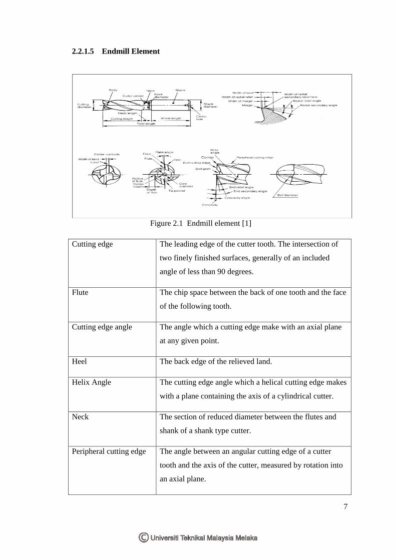
2.2.1.5 Endmill Element
Figure 2.1 Endmill element [1]
Cutting edge The leading edge of the cutter tooth. The intersection of
two finely finished surfaces, generally of an included
angle of less than 90 degrees.
Flute The chip space between the back of one tooth and the face
of the following tooth.
Cutting edge angle The angle which a cutting edge make with an axial plane
at any given point.
Heel The back edge of the relieved land.
Helix Angle The cutting edge angle which a helical cutting edge makes
with a plane containing the axis of a cylindrical cutter.
Neck The section of reduced diameter between the flutes and
shank of a shank type cutter.
Peripheral cutting edge The angle between an angular cutting edge of a cutter
tooth and the axis of the cutter, measured by rotation into
an axial plane.
8
Rake The angular relationship between the tooth face, or a
tangent to the tooth face at a given point and a given
reference plane or line.
Axial rake Applies to angular (not helical) flutes.
Helical rake Applies to helical teeth only (not angular).
Shank The projecting portion of a cutter which locates and drives
the cutter from the machine spindle or adapter.
2.3 Speed and Feed for Milling
Speeds and feeds are the most important factors to consider for best result in milling.
Improper feeds and speeds often cause low production, poor work quality and
unnecessary damage to the cutter. The speeds and feeds used depend on the material
to milling. For example, use lower speed ranges of hard materials, tough material,
abrasive material, heavy cuts, minimum tool wear and maximum cutting life. For
higher speed ranges is use of softer material, better finishes, smaller diameter cutter,
light cuts, maximum production rates and non-metallics material.
2.3.1 Milling composites
Nowadays many composite materials used in manufacturing because it have gained
popularity (despite their generally high cost) in high-performance products that need
to be lightweight, yet strong enough to take harsh loading conditions such
as aerospace components, boat and scull hulls, bicycle frames, swimming pool panels
and racing car bodies. Bases on [9], he concluded that higher cutting speeds give
better surface finish on milling composite. He also stated measurement of surface
roughness in FRP composite is less dependable than in metals, because protruding
9
fiber tips may lead to incorrect results. Conventional machining of fiber-reinforced
composites is difficult due to diverse fiber and matrix properties, fiber orientation,
inhomogeneous nature of the material, and the presence of high-volume fraction
(volume of fiber over total volume) of hard abrasive fiber in the matrix. Most of the
results on GFRP composite machining show that minimizing the surface roughness is
very difficult and it has to be controlled [9]. In order to get good surface quality and
dimensional properties, it is necessary to employ optimization techniques to find
optimal cutting parameters and theoretical models to do predictions [9]. Taguchi and
response surface methodologies can be conveniently used for these purposes.
2.4 Surface roughness
Surface roughness are used to determine and evaluate the quality of a product.
Surface roughness of a machined product could affect several of the product’s
functional attributes, such as contact causing surface friction, wearing, light
reflection, heat transmission, ability of distributing and holding a lubricant, coating,
and resisting fatigue [6]. Furthermore, the surface quality acts a very important role in
the performance of milling as a good –quality milled surface significantly improves
fatigue strength, corrosion resistance, or creep life of a product. The final surface
roughness might be considered as the sum of two independent effects [7]:
1) The ideal surface roughness are a result of the geometry of the tool and feed
rate and
2) The natural surface roughness are a result of the irregularities in the cutting
operation
10
2.5 Cutting Tool Material
The selection of cutting tool materials for a particular application is important factors
in machining operations. Consequently, the cutting tool material must possess the
following characteristics:
Have sufficient hardness to cut other material.
Capable of retaining hardness at high temperature.
Must rank high in wear resistance
Currently, the two general classes of tool materials cover the requirements of milling
operations. These are the high speed steels and carbide tool materials. Other tool
materials such as ceramics and compacted diamond are used in milling. Coatings and
surface finishes have also in use enhanced tool life [1].
2.5.1 High speed Steel
The high speed steels are tool steels capable of maintaining a useful cutting hardness
at important temperatures. They do not lose hardness permanently unless exposed to
temperatures higher than the tempering temperatures which are in excess of 100°F.
This property, often called red hardness, is due principally to two alloying elements,
molybdenum and tungsten, separately or in combination. High speed steels are
classified as “M” or “T” types depending upon which is the major alloying element.
All high speed steels also contain carbon, vanadium and chromium while some
grades also include cobalt as an alloying element.
High-speed steel has following advantages:
HSS costs less than carbide or ceramic tooling
HSS is less brittle and not as likely to break during interrupted cuts
HSS tool can be re-shaped easily