effect of groundwater flow on remediation of dissolved-phase voc contamination using air sparging
TRANSCRIPT
Ž .Journal of Hazardous Materials 72 2000 147–165www.elsevier.nlrlocaterjhazmat
Effect of groundwater flow on remediation ofdissolved-phase VOC contamination using air
sparging
Krishna R. Reddy ), Jeffrey A. AdamsUniÕersity of Illinois at Chicago, Department of CiÕil and Materials Engineering, 2095 Engineering Research
Facility, 842 West Taylor Street, Chicago, IL 60607, USA
Abstract
This paper presents two-dimensional laboratory experiments performed to study how ground-water flow may affect the injected air zone of influence and remedial performance, and howinjected air may alter subsurface groundwater flow and contaminant migration during in situ airsparging. Tests were performed by subjecting uniform sand profiles contaminated with dissolved-phase benzene to a hydraulic gradient and two different air flow rates. The results of the tests werecompared to a test subjected to a similar air flow rate but a static groundwater condition. The testresults revealed that the size and shape of the zone of influence were negligibly affected bygroundwater flow, and as a result, similar rates of contaminant removal were realized within thezone of influence with and without groundwater flow. The air flow, however, reduced thehydraulic conductivity within the zone of influence, reducing groundwater flow and subsequentdowngradient contaminant migration. The use of a higher air flow rate further reduced thehydraulic conductivity and decreased groundwater flow and contaminant migration. Overall, thisstudy demonstrated that air sparging may be effectively implemented to intercept and treat amigrating contaminant plume. q 2000 Elsevier Science B.V. All rights reserved.
Keywords: In situ air sparging; VOCs; Groundwater remediation; Groundwater flow; Saturated soils
1. Introduction
In situ air sparging has proven to be an effective means of remediating saturated soilsŽ .and groundwater that have been contaminated with volatile organic compounds VOCs .
However, little is known about how site-specific subsurface variables, namely soil
) Corresponding author. Tel.: q1-312-996-4755; fax: q1-312-996-2426; e-mail: [email protected]
0304-3894r00r$ - see front matter q 2000 Elsevier Science B.V. All rights reserved.Ž .PII: S0304-3894 99 00138-7
( )K.R. Reddy, J.A. AdamsrJournal of Hazardous Materials 72 2000 147–165148
heterogeneity, contaminant typerlocation, and groundwater flow affect the relativecontributions of the mass transfer, transport, and transformation mechanisms that are
w xcritical to the remedial performance of air sparging 1–3 .In relatively permeable soils like sands or gravels, groundwater flow can be relatively
high. If dissolved-phase VOC contamination resides within such soils, groundwater flowcan substantially smear the contaminant plume, greatly expanding the size of thecontaminant plume beyond the original spill. When air is injected into these soils duringair sparging, not only will vapor-phase partitioning of the contamination occur, theinjected air during air sparging will affect the flow of the groundwater passing throughthe zone of influence. Additionally, the flowing groundwater may affect the air flow andtherefore the size and shape of the resulting zone of influence. The interaction between
Ž .the two migrating fluids air and water may adversely affect the performance of airsparging.
Very few studies have addressed the effects of groundwater flow on air spargingw xperformance. Rutherford and Johnson 4 performed a laboratory study to investigate the
effects of air flow and groundwater flow on oxygenation rates during the use of airŽsparging. It was determined that when low air injection rates were utilized Q -10air
.lrmin , the injected air had little effect on the water flow field. Increased air flow led toa larger zone of influence and a greater air channel density within the zone of influence.The increased air channel density led to an increased airrwater interfacial area,increasing the rate of oxygenation of the flowing groundwater. Once an air injection rateof 20 lrmin was reached, further increases in air injection rates did not increase the sizeof the zone of influence or the air channel density within the zone of influence. The highair injection rate, however, affected groundwater flow; the increased air saturationwithin the zone of influence decreased the relative permeability of water, forcing theflowing groundwater to circumvent the zone of influence. Because the water avoided thezone of influence, the rate of oxygenation of the groundwater was reduced as a result ofthe reduced airrwater interfacial area.
w xGordon 5 reported a field system where air sparging is used for the treatment ofmigrating contaminant plumes and prevention of off-site migration. The system included134 air injection wells and 58 soil vapor extraction wells arranged in 15 legs. Except inthe potential source areas where the legs are arranged to provide maximum coverage, thelegs are oriented perpendicular to groundwater flow to serve as curtains to downgradientflow. The legs are sequentially pulsed for increased treatment. No skirting of thetreatment zone was observed, and it was determined that the redundant legs providedmore efficient treatment.
Under most natural groundwater flow conditions, volumetric flux through aquifermaterial is small. Even for thick aquifers, flow is on the order of a few liters per minute.Instead of a network of injection wells, either an open trench or a trench backfilled withcohesionless soil sparged with air was suggested as an effective method to remediate
w xand also prevent off-site contaminant migration 6 . Based on such a concept, Marley etw xal. 7 reported an air sparging system used to prevent VOC migration at a site in the
eastern USA. To prevent the contaminant plume from migrating into a nearby stream, a360-ft long segmented trench was installed to intercept the VOC plume. The 1-m widetrench was backfilled with material that had a greater hydraulic conductivity than the
( )K.R. Reddy, J.A. AdamsrJournal of Hazardous Materials 72 2000 147–165 149
native soil. Additionally, the air flow rate was carefully chosen to achieve target cleanuprates while limiting the reduction of relative permeability for water flow within thetrench. This prevented the groundwater from circumventing the trench.
To date, a critical assessment of how injected air flow is affected by groundwaterflow and vice versa has not been made. Additionally, the relative contributions ofvolatilization and removal and off-site advective–dispersive transport of contaminantswith groundwater are unknown. This study presents the results of controlled physicalmodel tests conducted to determine how air sparging will be affected in settings withconsiderable groundwater flow as well as how to optimize remediation of dissolved-phaseVOC contamination under such conditions. Such an investigation is necessary becausedissolved-phase VOC contamination often exists within the mobile fraction of ground-water and thus may be subjected to substantial off-site migration due to groundwaterflow. It is essential to determine how air sparging can be implemented to remediate thistype of contaminant condition as well as help prevent further off-site contaminantmigration.
2. Objectives and scope
The objective of this investigation is to assess the interaction between injected airflow and groundwater flow and determine how this interaction affects air flow patternsand ultimately the performance of air sparging. Additionally, the contributions ofcontaminant removal through volatilizationrvapor-phase partitioning and groundwaterflow-induced advective–dispersive transport were assessed. Two-dimensional aquifersimulation tests utilizing homogeneous coarse sand soil profiles contaminated withdissolved-phase benzene subjected to a groundwater flow were conducted. Two differentair injection rates were utilized to study how different air injection rates affect airsparging performance under such conditions.
3. Experimental methodology
3.1. Experimental test setup
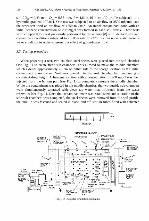
A two-dimensional aquifer simulation test setup, shown in Fig. 1, has been developedto study spatially dependent variables that affect air sparging. The large dimensions ofthe setup allow for the placement of a heterogeneous soil profile, including soil layers,lenses and other localized variations. The simulator also offers additional flexibility byallowing control of contaminant placement and options related to groundwater flow. A
w xdetailed description of the test setup is provided by Reddy and Adams 8 .
3.2. Testing program
Two tests were performed to study the effect of groundwater flow on the removal ofa dissolved VOC plume using air sparging. Both tests used a homogeneous coarse sand
( )K.R. Reddy, J.A. AdamsrJournal of Hazardous Materials 72 2000 147–165150
Ž y2 .soil D s0.43 mm, D s0.55 mm, ks4.64=10 cmrs profile subjected to a10 50
hydraulic gradient of 0.011. One test was subjected to an air flow of 2500 mlrmin, andthe other test used an air flow of 4750 mlrmin. An initial contaminant zone with aninitial benzene concentration of 200 mgrl was formed in each soil profile. These tests
w xwere compared to a test previously performed by the authors 8 with identical soil andcontaminant conditions subjected to air flow rate of 2225 mlrmin under static ground-water condition in order to assess the effect of groundwater flow.
3.3. Testing procedure
When preparing a test, two stainless steel sheets were placed into the soil chamberŽ .see Fig. 1 to create three sub-chambers. This allowed to make the middle chamber,which extends approximately 20 cm on either side of the sparge location as the initialcontaminant source zone. Soil was placed into the soil chamber by maintaining aconsistent drop height. A benzene solution with a concentration of 200 mgrl was then
Ž .injected from the bottom port see Fig. 1 to completely saturate the middle chamber.While the contaminant was placed in the middle chamber, the two outside sub-chamberswere simultaneously saturated with clean tap water that infiltrated from the water
Ž .reservoirs see Fig. 1 . Once the contaminant zone was established and saturation of theside sub-chambers was completed, the steel sheets were removed from the soil profile,the tank lid was fastened and sealed in place, and effluent air tubes fitted with activated
Fig. 1. 2-D aquifer simulation apparatus.
( )K.R. Reddy, J.A. AdamsrJournal of Hazardous Materials 72 2000 147–165 151
carbon filters were fastened to the tank lid effluent ports. The initial benzene concentra-tion distribution was determined through sampling and analysis of the pore water fromthe sampling ports. A detailed description of the soil profile, benzene solution, and the
w xinitial contaminant zone is provided by Reddy and Adams 8 .To study the effect of groundwater flow, a groundwater gradient was established
across the soil profile. The adjustable water reservoirs were adjusted to provide thedesired water level within the tank reservoirs. The height difference in the water levelsbetween the influent and effluent reservoirs was maintained at 1 cm, providing a
Ž .gradient, Dhrl , of 0.011 over the 91-cm length of the soil profile. Once the gradientand a steady discharge flow rate were established, air injection began.
During the course of testing, air was continuously injected at a specified flow rateŽand injection pressure. Two air injection rates were used: 2500 mlrmin denoted as low
. Ž .air flow and 4750 mlrmin denoted as high air flow . Both air flow rates were injectedunder a pressure of 4.5 kPa. Pore water sampling and analysis were performed in the
w xsame manner as described by Reddy and Adams 8 . Additionally, both the water withinthe outlet reservoir and the effluent flow from the test apparatus were analyzed forbenzene regularly to determine the extent of benzene migration andror removal as aresult of the migrating groundwater. The effluent groundwater flow passed through acarbon filter to remove benzene before discharging.
4. Results and analysis
4.1. Air injection without groundwater flow
A test was performed in which a homogeneous coarse sand soil profile contaminatedwith dissolved-phase benzene was subjected to air sparging with an injection rate of
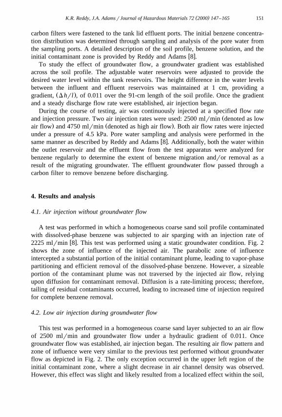
w x2225 mlrmin 8 . This test was performed using a static groundwater condition. Fig. 2shows the zone of influence of the injected air. The parabolic zone of influenceintercepted a substantial portion of the initial contaminant plume, leading to vapor-phasepartitioning and efficient removal of the dissolved-phase benzene. However, a sizeableportion of the contaminant plume was not traversed by the injected air flow, relyingupon diffusion for contaminant removal. Diffusion is a rate-limiting process; therefore,tailing of residual contaminants occurred, leading to increased time of injection requiredfor complete benzene removal.
4.2. Low air injection during groundwater flow
This test was performed in a homogeneous coarse sand layer subjected to an air flowof 2500 mlrmin and groundwater flow under a hydraulic gradient of 0.011. Oncegroundwater flow was established, air injection began. The resulting air flow pattern andzone of influence were very similar to the previous test performed without groundwaterflow as depicted in Fig. 2. The only exception occurred in the upper left region of theinitial contaminant zone, where a slight decrease in air channel density was observed.However, this effect was slight and likely resulted from a localized effect within the soil,
( )K.R. Reddy, J.A. AdamsrJournal of Hazardous Materials 72 2000 147–165152
Fig. 2. Air flow pattern in saturated coarse sand: air flow artes2250 mlrmin and static groundwatercondition.
such as a lower void ratio, as opposed to migrating groundwater. It is important to notethat the groundwater flow did not affect the size or shape of the zone of influence.
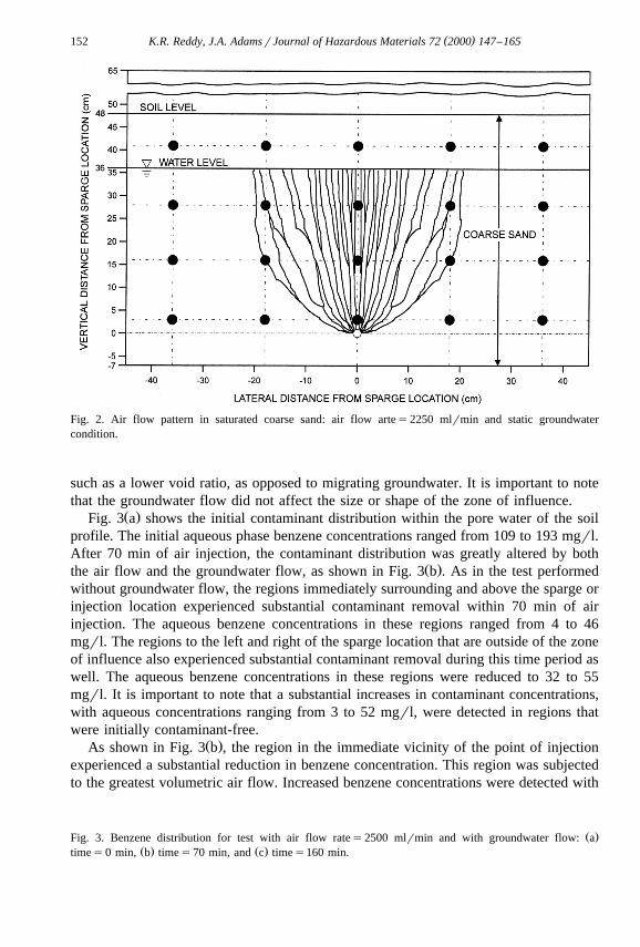
Ž .Fig. 3 a shows the initial contaminant distribution within the pore water of the soilprofile. The initial aqueous phase benzene concentrations ranged from 109 to 193 mgrl.After 70 min of air injection, the contaminant distribution was greatly altered by both
Ž .the air flow and the groundwater flow, as shown in Fig. 3 b . As in the test performedwithout groundwater flow, the regions immediately surrounding and above the sparge orinjection location experienced substantial contaminant removal within 70 min of airinjection. The aqueous benzene concentrations in these regions ranged from 4 to 46mgrl. The regions to the left and right of the sparge location that are outside of the zoneof influence also experienced substantial contaminant removal during this time period aswell. The aqueous benzene concentrations in these regions were reduced to 32 to 55mgrl. It is important to note that a substantial increases in contaminant concentrations,with aqueous concentrations ranging from 3 to 52 mgrl, were detected in regions thatwere initially contaminant-free.
Ž .As shown in Fig. 3 b , the region in the immediate vicinity of the point of injectionexperienced a substantial reduction in benzene concentration. This region was subjectedto the greatest volumetric air flow. Increased benzene concentrations were detected with
Ž .Fig. 3. Benzene distribution for test with air flow rates2500 mlrmin and with groundwater flow: aŽ . Ž .times0 min, b times70 min, and c times160 min.
( )K.R. Reddy, J.A. AdamsrJournal of Hazardous Materials 72 2000 147–165 153
( )K.R. Reddy, J.A. AdamsrJournal of Hazardous Materials 72 2000 147–165154
increasing height above the injection point as a result of lower air channel density,leading to less efficient benzene vapor-phase partitioning due to saturation of themigrating air. Additionally, regions in the middle and upper left and right of the initialcontaminant zone experienced major benzene concentration reductions. The regionsimmediately to the left and right of the point of injection experienced sizable benzeneconcentration reductions, but the rate of removal was lower in these regions than inother initially contaminated regions. Further injection led to continued contaminant
Ž .concentration reductions. As shown in Fig. 3 c , minor concentrations were detectedwithin the zone of influence after 160 min of air injection.
The substantial removal that occurred from the initial contaminant zone is the resultof two important mass transfer phenomena. First, a zone of influence with a high densityof pore scale air channels created a large interfacial mass transfer area. The resultinghigh air saturation greatly expedited the partitioning of dissolved-phase benzene into thevapor phase through volatilization. Regions in the vicinity of the injection point
Žexperienced faster benzene removal due to higher air flow density and saturation thelateral expansion of the zone of influence with increased elevation reduced the density
.of air flow and interfacial mass transfer area in the upper contaminant regions . Also, themigrating air induced vertical contaminant migration due to advective–dispersive trans-port by the groundwater. This migration did not produce any substantial degree ofincreased benzene concentration because the migrating air responsible for the contami-nant migration also accounted for removal through volatilization.
Dissolved-phase benzene removal due to vapor-phase partitioning did not, however,account for total removal of benzene mass within the initial contaminant zone. Advec-tive–dispersive transport induced by groundwater flow resulted in lateral benzenemigration. In regions of high groundwater flow, advective transport controls masstransfer. This is verified by the substantial increases in benzene concentration in regions
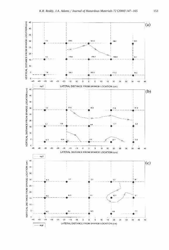
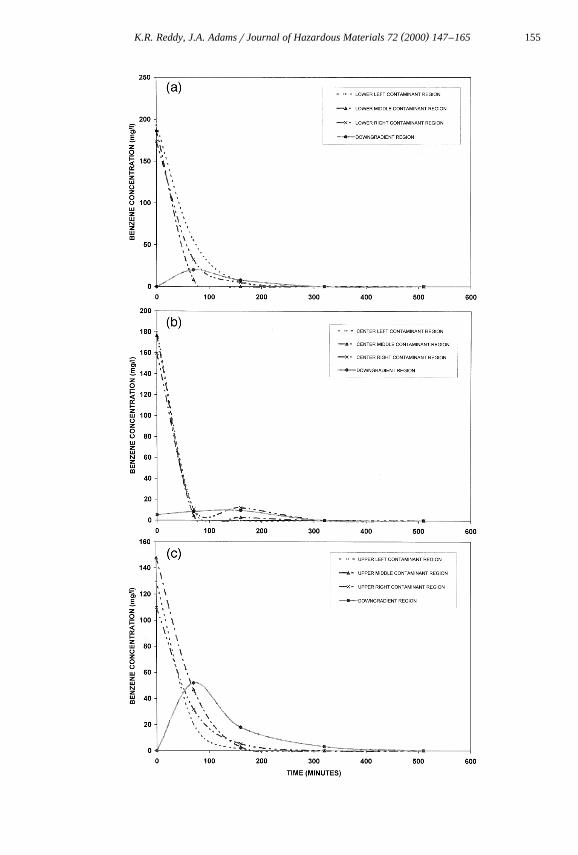
Ž .downgradient from the initial contaminant zone. As shown in Fig. 4 a , the regiondowngradient from the lower region of the initial contaminant zone experienced
Ž .aqueous-phase benzene infiltration after 70 min of air injection. While Fig. 4 b depictslittle downgradient migration from the middle region of the initial contaminant zone,
Ž .Fig. 4 c shows that a sizable downgradient infiltration occurred from the upper regionŽ .of the initial contaminant zone. Fig. 4 c shows that after 70 min of air injection, a
benzene concentration of 50 mgrl was detected downgradient from the upper region ofthe initial contaminant zone. Additionally, benzene was detected in both the downgradi-ent water reservoir as well as the effluent groundwater flow from the soil profile.
The migration of groundwater also accounted for the removal of benzene from theregions to the left and the right of the injection point. The benzene in the region to theleft of the injection point migrated through groundwater flow-induced advective–disper-sive transport towards the injection point. Upon entering the zone of influence, themigrating benzene efficiently partitioned into the vapor phase through volatilization.Benzene initially located within the right side of the initial contaminated region,
Fig. 4. Benzene concentration vs. elapsed time for test with air flow rates2500 mlrmin and withŽ . Ž . Ž .groundwater flow: a lower regions, b center regions, and c upper regions.
( )K.R. Reddy, J.A. AdamsrJournal of Hazardous Materials 72 2000 147–165 155
( )K.R. Reddy, J.A. AdamsrJournal of Hazardous Materials 72 2000 147–165156
especially within the region immediately to the right of the injection point, never enteredinto the zone of influence and as a result migrated downgradient due to advective–dis-persive transport. The benzene within the middle and upper regions of the initialcontaminant zone also migrated through groundwater flow-induced advective–dispersivetransport, but since the zone of influence encompassed these regions, off-site migrationfrom these regions was minimized.
The high degree of air saturation within the zone of influence reduced the relativewater permeability, which in turn reduced groundwater flow-induced advective–disper-sive transport of contamination from regions within and upgradient from the zone ofinfluence. Additionally, the reduced water flow rate increased the residence time ofthe groundwater within the zone of influence. As a result, the contribution ofaqueousrvapor-phase benzene partitioning is increased. Therefore, by reducing perme-ability, the extent of off-site advective–dispersive transport of groundwater migration isreduced. Although not included in this study, measurement of degree of air saturationand consequent effects on the relative permeability of water and air phases will helpexplain the flow dynamics and contaminant removal.
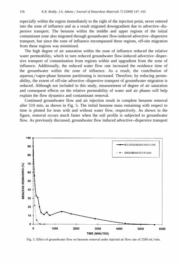
Continued groundwater flow and air injection result in complete benzene removalafter 510 min, as shown in Fig. 5. The initial benzene mass remaining with respect totime is plotted for tests with and without water flow, respectively. As shown in thefigure, removal occurs much faster when the soil profile is subjected to groundwaterflow. As previously discussed, groundwater flow induced advective–dispersive transport
Fig. 5. Effect of groundwater flow on benzene removal under injected air flow rate of 2500 mlrmin.
( )K.R. Reddy, J.A. AdamsrJournal of Hazardous Materials 72 2000 147–165 157
of dissolved-phase benzene out of the profile, accounting for a portion of the initialbenzene mass. The groundwater also caused portions of the plume upgradient from thezone of influence to migrate into the zone of influence, leading to vapor-phasepartitioning and removal. In the test without groundwater flow, contamination outside ofthe zone of influence had to migrate through diffusive transport into the zone ofinfluence for removal. This rate-limiting process led to lengthy remedial times requiredfor removal. Therefore, if sparging is implemented to intercept migrating contaminantplumes, the flow of groundwater will actually assist in contaminant delivery to thetreatment zone and faster overall removal.
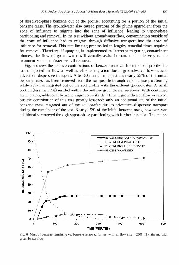
Fig. 6 shows the relative contributions of benzene removal from the soil profile dueto the injected air flow as well as off-site migration due to groundwater flow-inducedadvective–dispersive transport. After 60 min of air injection, nearly 55% of the initialbenzene mass has been removed from the soil profile through vapor phase partitioningwhile 20% has migrated out of the soil profile with the effluent groundwater. A small
Ž .portion less than 2% resided within the outflow groundwater reservoir. With continuedair injection, additional benzene migration with the effluent groundwater flow occurred,but the contribution of this was greatly lessened; only an additional 7% of the initialbenzene mass migrated out of the soil profile due to advective–dispersive transportduring the remainder of the test. Nearly 15% of the initial benzene mass, however, wasadditionally removed through vapor-phase partitioning with further injection. The major-
Fig. 6. Mass of benzene remaining vs. benzene removed for test with air flow rates2500 mlrmin and withgroundwater flow.
( )K.R. Reddy, J.A. AdamsrJournal of Hazardous Materials 72 2000 147–165158
ity of the benzene mass that migrated out of the soil profile with effluent groundwaterflow initially existed in regions downgradient from the zone of influence. The benzenemass initially within or upgradient from the zone of influence was removed throughvolatilization, although a minimal portion migrated out of the zone of influence with thegroundwater flow.
4.3. High air injection during groundwater flow
To study the effect of increased air flow on air saturation and its potential to controlspreading of contaminants, an additional test was performed using an increased airinjection rate of 4750 mlrmin. Once groundwater flow was established, air injectionbegan. The resulting zone of influence was very similar to that observed in the previoustest. Since a higher volumetric air flow was confined to the same region of flow, agreater air saturation within the zone of influence resulted. A greater interfacial masstransfer area was developed for benzene to partition into the vapor phase as well as
w xreduced relative permeability for groundwater flow. Rutherford and Johnson 4 deter-mined that increased air flow increased the size of the zone of influence and air channeldensity; however, an enlarged zone of influence was not observed during this test;rather, a greater air channel density was observed.
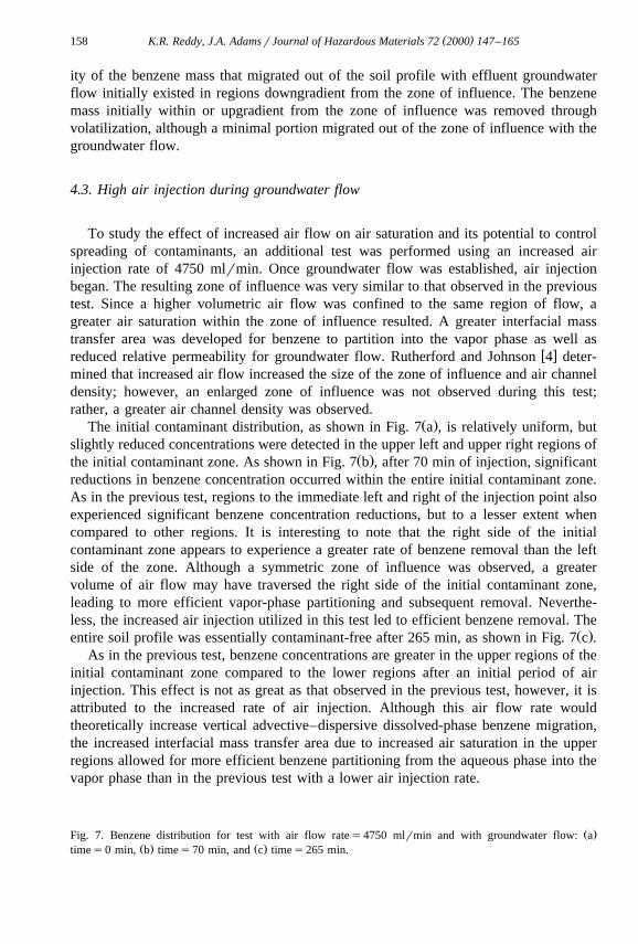
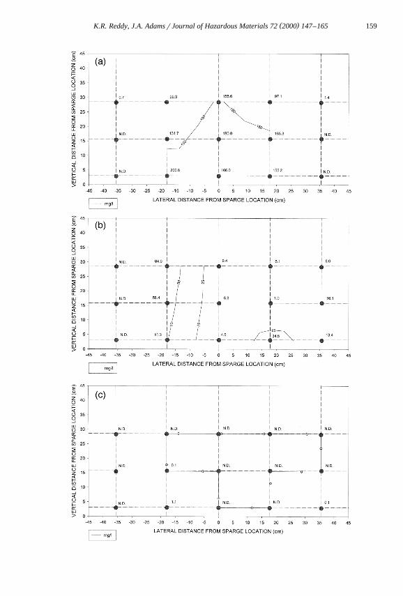
Ž .The initial contaminant distribution, as shown in Fig. 7 a , is relatively uniform, butslightly reduced concentrations were detected in the upper left and upper right regions of
Ž .the initial contaminant zone. As shown in Fig. 7 b , after 70 min of injection, significantreductions in benzene concentration occurred within the entire initial contaminant zone.As in the previous test, regions to the immediate left and right of the injection point alsoexperienced significant benzene concentration reductions, but to a lesser extent whencompared to other regions. It is interesting to note that the right side of the initialcontaminant zone appears to experience a greater rate of benzene removal than the leftside of the zone. Although a symmetric zone of influence was observed, a greatervolume of air flow may have traversed the right side of the initial contaminant zone,leading to more efficient vapor-phase partitioning and subsequent removal. Neverthe-less, the increased air injection utilized in this test led to efficient benzene removal. The
Ž .entire soil profile was essentially contaminant-free after 265 min, as shown in Fig. 7 c .As in the previous test, benzene concentrations are greater in the upper regions of the
initial contaminant zone compared to the lower regions after an initial period of airinjection. This effect is not as great as that observed in the previous test, however, it isattributed to the increased rate of air injection. Although this air flow rate wouldtheoretically increase vertical advective–dispersive dissolved-phase benzene migration,the increased interfacial mass transfer area due to increased air saturation in the upperregions allowed for more efficient benzene partitioning from the aqueous phase into thevapor phase than in the previous test with a lower air injection rate.
Ž .Fig. 7. Benzene distribution for test with air flow rates4750 mlrmin and with groundwater flow: aŽ . Ž .times0 min, b times70 min, and c times265 min.
( )K.R. Reddy, J.A. AdamsrJournal of Hazardous Materials 72 2000 147–165 159
( )K.R. Reddy, J.A. AdamsrJournal of Hazardous Materials 72 2000 147–165160
The increased air flow not only expedited removal through volatilization due toincreased air saturation and mass transfer area, the increased air saturation also reducedbenzene advective–dispersive transport due to groundwater flow. The increased rate ofaqueousrvapor phase partitioning contributed to reduced off-site migration, but theincreased air saturation also reduced the relative permeability for groundwater flow. As
Ž .shown in Fig. 7 b , regions downgradient from the zone of influence that were initiallyfree of benzene concentration experienced infiltration due to groundwater-inducedadvective–dispersive transport, but the extent of this effect is lessened when comparedto the previous test utilizing a lower air injection rate.
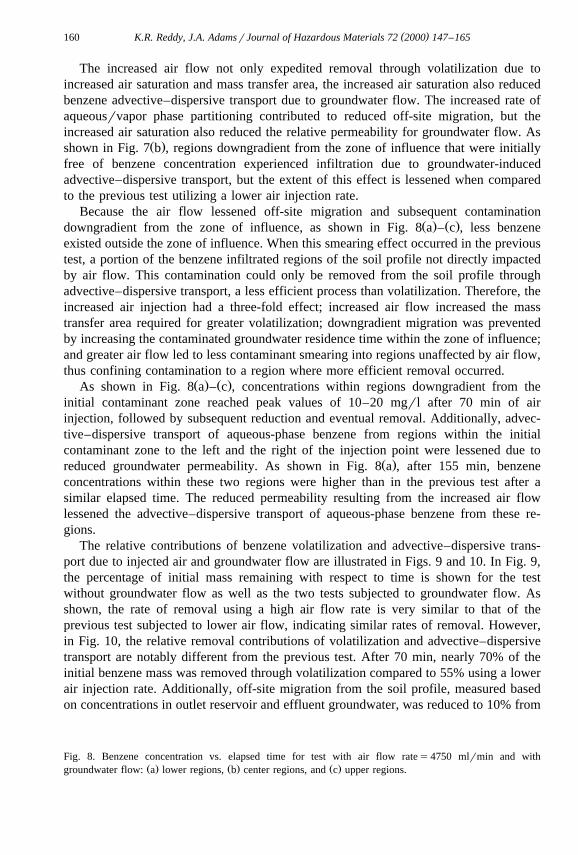
Because the air flow lessened off-site migration and subsequent contaminationŽ . Ž .downgradient from the zone of influence, as shown in Fig. 8 a – c , less benzene
existed outside the zone of influence. When this smearing effect occurred in the previoustest, a portion of the benzene infiltrated regions of the soil profile not directly impactedby air flow. This contamination could only be removed from the soil profile throughadvective–dispersive transport, a less efficient process than volatilization. Therefore, theincreased air injection had a three-fold effect; increased air flow increased the masstransfer area required for greater volatilization; downgradient migration was preventedby increasing the contaminated groundwater residence time within the zone of influence;and greater air flow led to less contaminant smearing into regions unaffected by air flow,thus confining contamination to a region where more efficient removal occurred.
Ž . Ž .As shown in Fig. 8 a – c , concentrations within regions downgradient from theinitial contaminant zone reached peak values of 10–20 mgrl after 70 min of airinjection, followed by subsequent reduction and eventual removal. Additionally, advec-tive–dispersive transport of aqueous-phase benzene from regions within the initialcontaminant zone to the left and the right of the injection point were lessened due to
Ž .reduced groundwater permeability. As shown in Fig. 8 a , after 155 min, benzeneconcentrations within these two regions were higher than in the previous test after asimilar elapsed time. The reduced permeability resulting from the increased air flowlessened the advective–dispersive transport of aqueous-phase benzene from these re-gions.
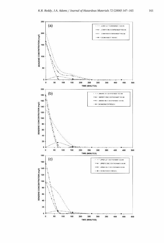
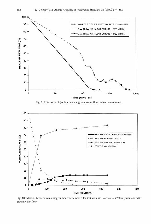
The relative contributions of benzene volatilization and advective–dispersive trans-port due to injected air and groundwater flow are illustrated in Figs. 9 and 10. In Fig. 9,the percentage of initial mass remaining with respect to time is shown for the testwithout groundwater flow as well as the two tests subjected to groundwater flow. Asshown, the rate of removal using a high air flow rate is very similar to that of theprevious test subjected to lower air flow, indicating similar rates of removal. However,in Fig. 10, the relative removal contributions of volatilization and advective–dispersivetransport are notably different from the previous test. After 70 min, nearly 70% of theinitial benzene mass was removed through volatilization compared to 55% using a lowerair injection rate. Additionally, off-site migration from the soil profile, measured basedon concentrations in outlet reservoir and effluent groundwater, was reduced to 10% from
Fig. 8. Benzene concentration vs. elapsed time for test with air flow rates4750 mlrmin and withŽ . Ž . Ž .groundwater flow: a lower regions, b center regions, and c upper regions.
( )K.R. Reddy, J.A. AdamsrJournal of Hazardous Materials 72 2000 147–165 161
( )K.R. Reddy, J.A. AdamsrJournal of Hazardous Materials 72 2000 147–165162
Fig. 9. Effect of air injection rate and groundwater flow on benzene removal.
Fig. 10. Mass of benzene remaining vs. benzene removed for test with air flow rates4750 mlrmin and withgroundwater flow.
( )K.R. Reddy, J.A. AdamsrJournal of Hazardous Materials 72 2000 147–165 163
nearly 20% using a lower air injection rate. Upon completion of the test, nearly 85% ofthe initial benzene mass was removed from the soil profile through volatilization,thereby reducing off-site effluent benzene migration to 15% of the initial mass.Although the removal rates were similar for both air flow rates, the higher air flow rateresulted in greater volatilization contribution to contaminant removal and reducedoff-site contaminant migration due to groundwater flow.
Benzene that migrated with the groundwater was initially located downgradient fromthe zone of influence. Benzene initially located within or upgradient from the zone ofinfluence was effectively prevented from migrating downgradient from the zone ofinfluence. Increased air flow lessened the contribution of advective–dispersive transport.Therefore, it demonstrates that increased air flow will lessen downgradient migration ofa contaminated groundwater plume, reducing off-site contamination.
5. Practical implications
The results of this study have numerous implications for field application of airŽ .sparging. Air sparging can be used in relatively permeable soils e.g., sands , under
groundwater flow conditions. However, caution must be exercised for the potentialsmearing of the contaminant plume, resulting in downgradient contaminant migrationunder groundwater flow conditions.
Air sparging results in increased air saturation, consequently reducing the relativehydraulic conductivity. The reduced hydraulic conductivity results in reduced groundwa-ter flow and subsequent downgradient contaminant migration. Using an increased airinjection rate may further reduce hydraulic conductivity; however, too much air injectionmay reduce the relative hydraulic conductivity to the extent that groundwater flow maybypass the zone of influence. Therefore, a careful assessment of the changes in relativepermeability of water and air phases and their effects on the groundwater flow andcontaminant removal should be performed.
Under groundwater flow conditions, remedial strategy may include using air spargingas a ‘‘fence’’ to intercept the contaminant plume. If the air injection flow rate does notcreate preferential groundwater flow, air sparging may be used to effectively interceptand treat migrating contaminant plumes. Care must be taken to assure that the entirecontaminant plume is intercepted to prevent contaminant from circumventing thetreatment zone. Additionally, an air sparging system must be designed to effectivelyintercept the entire contaminant plume and assure that contamination does not initiallyreside downgradient from the zone of influence.
6. Conclusions
This study investigated the effects of groundwater flow on the performance of airsparging. Homogeneous coarse sand profiles contaminated with dissolved-phase benzenewere subjected to a hydraulic gradient of 0.011 as well as a no-flow condition. Two
( )K.R. Reddy, J.A. AdamsrJournal of Hazardous Materials 72 2000 147–165164
different air injection rates were used to investigate how injected air interacts withgroundwater flow. The following conclusions may be drawn from this study.
Ž .1 The shape of the injected air zone of influence was not affected by groundwaterflow when the hydraulic gradient was less than or equal to 0.011. The shape of the zoneof influence was very similar to that observed without groundwater flow. In both cases,the zone of influence featured similar air channel density and air saturation, and, as aresult, similar removal rates due to volatilization were realized.
Ž .2 The injected air flow did not prevent contaminant migration into regions initiallyfree of contamination. The relative hydraulic conductivity within the zone of influence,however, was reduced, reducing advective–dispersive transport of contamination down-gradient of the initial contaminant zone due to groundwater flow. Increased air flowfurther decreased the relative hydraulic conductivity and led to reduced downgradientcontaminant migration resulting from groundwater flow. Too high of an injection rate,however, may be problematic, as preferential groundwater flow may cause contamina-tion to circumvent the treatment zone. It was determined that most of the off-sitecontaminant migration resulted from contaminant initially located downgradient fromthe zone of influence, illustrating the need to assure that air is injected in or downgradi-ent from contaminated regions.
Ž .3 When air was injected into the soil profile, aqueous-phase benzene was able topartition into the vapor phase over the mass transfer area resulting from the increased airsaturation within the zone of influence. Advective–dispersive mass transport of thebenzene also resulted from air injection. The air injection-induced transferrtransportprocesses were shown to dominate over the advective mass transport induced bygroundwater flow, demonstrating that air sparging can be effectively implementedwithin contaminated soils subjected to groundwater flow for remediation and to helpprevent downgradient migration.
Acknowledgements
Financial support for this study was provided by National Science Foundation GrantCMS-9813466. The support of this agency is gratefully acknowledged. The authors aregrateful to Willard Murray of Harding Lawson Associates for reviewing this paper andproviding useful comments and John Gramsas of UIC for his assistance in the designand construction of the experimental setup.
References
w x1 K.R. Reddy, S. Kosgi, J. Zhou, A review of in situ air sparging for the remediation of VOC-contaminatedŽ .saturated soils and groundwater, Hazardous Waste & Hazardous Materials 12 1995 97–118.
w x2 K.R. Reddy, J.A. Adams, System effects on benzene removal from saturated soils and groundwater usingŽ .air sparging, Journal of Environmental Engineering, ASCE 128 1998 288–299.
w x3 J.A. Adams, K.R. Reddy, Laboratory study of air sparging of TCE-contaminated saturated soils andŽ .ground water, Ground Water Monitoring and Remediation 19 1999 182–190.
( )K.R. Reddy, J.A. AdamsrJournal of Hazardous Materials 72 2000 147–165 165
w x4 K.W. Rutherford, P.C. Johnson, Effects of process control changes on aquifer oxygenation rates during inŽ .situ air sparging in homogenous aquifers, Ground Water Monitoring Review 16 1996 132–141.
w x5 M.J. Gordon, Case history of a large-scale air spargingr soil vapor extraction system for the remediationof chlorinated volatile organic compounds in ground water, Ground Water Monitoring and Remediation 18Ž .1998 137–149.
w x6 J.F. Pankow, R.L. Johnson, J.A. Cherry, Air sparging in gate wells in cutoff wells and trenches for controlŽ . Ž .of plumes of volatile organic compounds VOCs , Ground Water 31 1993 654–663.
w x7 M. Marley, F. Li, E. Droste, R. Cody, The design of an in situ sparging trench, Proceedings of PetroleumHydrocarbons and Organic Chemicals in Ground Water: Prevention, Detection, and Restoration, Houston,TX, 1994, pp. 579–590.
w x8 K.R. Reddy, J.A. Adams, Effects of soil heterogeneity on air flow patterns and hydrocarbon removalduring air sparging in saturated soils, in review.