ee09 502 epgtd
TRANSCRIPT

ELECTRICAL POWER GENERATION, TRANSMISSION
AND DISTRIBUTION
KN. ChandraboseAsst.ProfessorEEE Dept. GECSunday, August 05, 2012 1
KN. Chandra Bose, Asst. Professor, GECT

Over View of Syllabus
Objectives:
To understand the various energy sources. To understand about transmission and Distribution schemes.
To evaluate the performance of power system.
Sunday, August 05, 2012 2
KN. Chandra Bose, Asst. Professor, GECT

Sources• Power generated is the compliments of our natural resources.
• Renewable and Non‐renewable.– A renewable resource is a natural resource with the ability to reproduce through biological or natural processes and replenished with the passage of time. Renewable resources are part of our natural environment and form our eco‐system.
– Solar radiation, tides, winds, geothermal, biomass and other natural elements.
Sunday, August 05, 2012 3
KN. Chandra Bose, Asst. Professor, GECT

Sources cntd…
• Power generated is the compliments of our natural resources.
• Non‐renewable.– Nonrenewable energy‐Energy that is impossible to re‐make.
– Natural resources such as coal, petroleum (crude oil) and natural gas take thousands of years to form naturally and cannot be replaced as fast as they are being consumed.
Sunday, August 05, 2012 4
KN. Chandra Bose, Asst. Professor, GECT

Sources cntd…
• Eventually natural resources will become too costly to harvest and humanity will need to find other sources of energy.
• Natural gas is a mixture of gases, the most common being methane (CH4). It also contains some ethane (C2H5), propane (C3H8), and butane (C4H10).
Sunday, August 05, 2012 5
KN. Chandra Bose, Asst. Professor, GECT

MODULE ‐ 1Hydro electric ThermalDieselNuclear
SolarWind TidalMHDGeothermal Fuel cells
CONVENTIONAL SOURCES OF ENERGY
NON‐CONVENTIONAL SOURCES OF ENERGY
Sunday, August 05, 2012 6
KN. Chandra Bose, Asst. Professor, GECT

MAIN GOAL: To provide an adequate and efficient natural
source of energy without burning of fossil fuels. To harness the energy of moving water. To provide a cheap source of energy.
Sunday, August 05, 2012 7
KN. Chandra Bose, Asst. Professor, GECT

CONVENTIONAL SOURCES OF ENERGY
Hydro electricity:• Hydro‐electric power is the power from the energy of falling water.
• Hydro‐electric plant is the power plant utilizing the potential energy of water at a height.
• Most widely used form of renewable energy and is produced in about 150 countries.
• Accounting for 16% of global electricity consumption, and 3,427 terawatt‐hours of electricity production in 2010.
Sunday, August 05, 2012 8
KN. Chandra Bose, Asst. Professor, GECT
CONVENTIONAL SOURCES OF ENERGY …
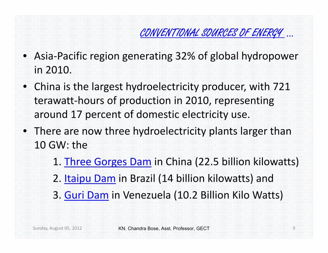
• Asia‐Pacific region generating 32% of global hydropower in 2010.
• China is the largest hydroelectricity producer, with 721 terawatt‐hours of production in 2010, representing around 17 percent of domestic electricity use.
• There are now three hydroelectricity plants larger than 10 GW: the
1. Three Gorges Dam in China (22.5 billion kilowatts)2. Itaipu Dam in Brazil (14 billion kilowatts) and3. Guri Dam in Venezuela (10.2 Billion Kilo Watts)
Sunday, August 05, 2012 9
KN. Chandra Bose, Asst. Professor, GECT

CONVENTIONAL SOURCES OF ENERGY …
• Reasons for extensive development of water power.– Tremendous increase in demand of electricity– High cost of fuels– Limited resources– Projects are multipurpose
• India has hydel potential of 600 billion units of firm annual energy.
• Only 23% of this has been utilized so far.
Sunday, August 05, 2012 10
KN. Chandra Bose, Asst. Professor, GECT

CONVENTIONAL SOURCES OF ENERGY …
• The average cost of electricity from a hydro plant, larger than 10 megawatts is 3 to 5 U.S. cents per kilowatt‐hour.
• The water flowing in the river possesses two type of energy: the kinetic energy due to flow of water and potential energy due to the height of water.
• In hydroelectric power plant, potential energy of water is utilized to generate electricity.
• The total power that can be generated from water in hydroelectric power plant is
Where w – specific wt of water in kg/m3 , Q – rate of flow of water in m3/s, H – Height of fall in meter's , – overall efficiency
Sunday, August 05, 2012 11
KN. Chandra Bose, Asst. Professor, GECT

CONVENTIONAL SOURCES OF ENERGY …
• In hydro‐electric power station, water head is created by constructing dam across a river.
Factors to be considered:‐ before a project site is considered.
– Capital cost of plant– Capital cost of erecting and maintaining the transmission lines, and annual energy loss in transformation and transmission of power.
– Energy generation cost compared with those in case of steam, oil or gas plants, which can be conveniently set up near the load centre.
Sunday, August 05, 2012 12
KN. Chandra Bose, Asst. Professor, GECT

CONVENTIONAL SOURCES OF ENERGY …
SELECTION OF SITE (HYDRO‐ELECTRIC PLANT):• Select site with natural storage and with large catchment area.
• High average rain fall, steep gradients, and suitable place for constructing reservoir.
FACTORS TO BE CONSIDERED:
1. Availability of water: ‐– Potential energy of water fall or kinetic energy of flowing stream is utilized for generation of power.
– Hence station should construct based on availability of water head.
Sunday, August 05, 2012 13
KN. Chandra Bose, Asst. Professor, GECT

CONVENTIONAL SOURCES OF ENERGY …
– Estimation of availability of energy from a stream or river is estimated on the discharge flow and its variation with time over a number of years.
2. Water storage:– Storage of water in a suitable reservoir at a height is essential in order to have continuous supply during dry season.
– A careful study of geology and topography of the catchment area is required, before the construction of dam.
3. Water Head:– Water head depends on the topography of the area.– Availability of head has considerable effect on the cost and economy of power generation.
Sunday, August 05, 2012 14
KN. Chandra Bose, Asst. Professor, GECT

CONVENTIONAL SOURCES OF ENERGY …
4. Distance from load centre:– Distance to be considered for economical transmission of power.
5. Accessibility of the site:– Adequate transportation facilities must be available.
6. Water pollution:– Polluted water must be eliminated from the site.– Pollution may cause excessive corrosion and damage to the metallic structures.
7. Sedimentation:– Gradual deposition of silt may reduce the capacity of reservoir.– Which may cause damage of turbine blades.
Sunday, August 05, 2012 15
KN. Chandra Bose, Asst. Professor, GECT

CONVENTIONAL SOURCES OF ENERGY …
• 8. Large catchment area:– Must have large catchment area, so that level of water in the reservoir may not fall below the minimum.
• 9. Availability of land:– Available land should be cheap in cost.– Rocky in order to withstand the weight of water, large buildings and machinery.
Sunday, August 05, 2012 16
KN. Chandra Bose, Asst. Professor, GECT

CONVENTIONAL SOURCES OF ENERGY …
How it Works: Build a dam on a large river that has a large drop in elevation. The dam stores lots of water behind it in the reservoir. Near the bottom of the dam wall, there is a water intake. Gravity causes it to fall through the penstock inside the dam. At the end of the penstock, there is a turbine propeller which is turned by the moving water.Sunday, August 05, 2012 17
KN. Chandra Bose, Asst. Professor, GECT

CONVENTIONAL SOURCES OF ENERGY …
The shaft from the turbine goes up into the generator, which rotates the armature, producing power.
Power lines are connected to the generator that carry electricity.
The water continues past the propeller through the tail‐race into the river past the dam.
Sunday, August 05, 2012 18
KN. Chandra Bose, Asst. Professor, GECT

CONVENTIONAL SOURCES OF ENERGY …
Sunday, August 05, 2012 19
ELEMENTS OF HYDRO PLANT1. STORAGE RESERVOIR2. DAM3. FOREBAY4. SPILLWAY5. INTAKE6. SURGE TANK7. PENSTOCK8. VALVES AND GATES9. TRASH RACKS10. TAIL RACE11. DRAFT TUBES12. PRIME MOVERS/ WATER TURBINES
KN. Chandra Bose, Asst. Professor, GECT

CONVENTIONAL SOURCES OF ENERGY …
Sunday, August 05, 2012 20
1. STORAGE RESERVOIR– Purpose is to store water during excess flow.– Can be of natural and artificial.– Natural reservoir is in the form of lake in high mountains with large storing capacity.
– Capacity of reservoir depends on the difference between run‐offs during high and lean (dry) flows.
2. DAM– Function of dam is not only to raise the water head, but also to provide the pondage, storage or the facility of diversion into conduits.
KN. Chandra Bose, Asst. Professor, GECT

CONVENTIONAL SOURCES OF ENERGY …
Sunday, August 05, 2012 21
– Dam is the most expensive and important part of hydro project.
– Built of concrete, earth or rock fill.– Choice of dam depends upon the foundation condition, local materials and transportation availability, occurrence of earth quakes and other hazards.
– Concrete or masonry dams are of three types:• Solid gravity• Buttress• Arch dam
KN. Chandra Bose, Asst. Professor, GECT

CONVENTIONAL SOURCES OF ENERGY …
Sunday, August 05, 2012 22
– Solid gravity dam:• Made of concrete and suitable for most sites.• Height of dam cannot be very high, depends on the strength of subsoil.
– Arch dam:• It is a curved dam and transmits a major portion of its water pressure horizontally to the abutments by arch action.
• Arch dam is preferred, where eve a narrow canyon width is available.
• It has inherent stability against sliding.
KN. Chandra Bose, Asst. Professor, GECT

CONVENTIONAL SOURCES OF ENERGY …
Sunday, August 05, 2012 23
• Buttress dam: – Buttress/deck dam has inclined up stream face.– So that water pressure creates a large downward force, provides stability against over turning or sliding.
3. FOREBAY– Mainly forebay provided before the Penstock, acts as water reservoir for medium head plants.
– Serves as a regulating reservoir storing water temporarily during light load period.
– Provides same for initial increase on account of increasing load.
– Mainly forebay provided before the Penstock, acts as water reservoir for medium head plants.
KN. Chandra Bose, Asst. Professor, GECT

CONVENTIONAL SOURCES OF ENERGY …
Sunday, August 05, 2012 24
• 4. SPILLWAY
– Act as a safety valve.– A spillway is located at the top of the reservoir pool.– Dams may also have bottom outlets with valves or gates which may be operated to release flood flow.
– Two main types of spillways: controlled and uncontrolled.
• A controlled spillway has mechanical structures or gatesto regulate the rate of flow.
• An uncontrolled spillway, in contrast, does not have gates; when the water rises above the lip or crest of the spillway it begins to be released from the reservoir.
KN. Chandra Bose, Asst. Professor, GECT

CONVENTIONAL SOURCES OF ENERGY …
Sunday, August 05, 2012 25
5. INTAKE– A penstock is a sluice or gate or intake structure that controls water flow, or an enclosed pipe that delivers water to hydraulic turbines.
– Intake structures are of two, High Pressure and small pressure.
6. SURGE TANK– Surge tanks are usually provided in high or medium‐head plants.
– The main functions of the surge tank are: • 1. When the load decreases, the water moves backwards and gets stored in it.
• 2. When the load increases, additional supply of water will be provided by surge tank.
KN. Chandra Bose, Asst. Professor, GECT

CONVENTIONAL SOURCES OF ENERGY …
Sunday, August 05, 2012 26
– Change in load creates a very high pressure in the penstock.
– Results in water hammer phenomenon, which may leads to penstock bursting.
– Surge Tanks are placed near to the Turbine.– The Height of Surge Tank is generally kept above the maximum Water Level in the supply Level Reservoir.
• There are three important types of Surge Tanks used in Hydro Electric Power Plant.01)Simple Surge Tank02)Restricted Orifice type Surge Tank03)Differential Surge Tank.
KN. Chandra Bose, Asst. Professor, GECT

CONVENTIONAL SOURCES OF ENERGY …
Sunday, August 05, 2012 27
– simple surge tank is of uniform cross section and is open to atmosphere.
– Directly connected to penstock.– Large in size with expensive proportions and sluggish.– Not common in common practice.– Restricted orifice surge tank is more efficient and
economical.– Drawback is the sudden creation of accelerating and
retarding heads in the conduits, results in proportional sudden fluctuations on the turbine.
– Differential surge tank is the best suited for practical case.
KN. Chandra Bose, Asst. Professor, GECT

CONVENTIONAL SOURCES OF ENERGY …
Sunday, August 05, 2012 28
7. PENSTOCK– A closed conduit for carrying water to turbine.– Penstocks are built of steel or reinforced concrete.– Thickness must be adequate to withstand the pressure.
8. Valves and gates– Control the flow of water into turbine.
KN. Chandra Bose, Asst. Professor, GECT

CONVENTIONAL SOURCES OF ENERGY …
Sunday, August 05, 2012 29
9. TRASH RACKS– Built up from long, flat bars set vertically spaced in accordance with minimum width of water passage through the turbine.
– Prevent the ingress of floating and other material to the turbine.
10. TAIL RACE– Tail race is the path through which water is pumped out of the hydro power plant after power generation.
11. Draft Tubes– An air tight pipe of suitable diameter attached to the runner outlet and conducting water down from the wheel.
KN. Chandra Bose, Asst. Professor, GECT

CONVENTIONAL SOURCES OF ENERGY …
Sunday, August 05, 2012 30
12. PRIME MOVERS/ WATER TURBINES– Hydro plants uses water turbine as prime movers.– Converting one form of energy into other.– Turbines are of mainly three types
• Pelton wheel ‐ Impulse type• Francis turbine ‐ Radial Flow• Kaplan turbine ‐ Axial Flow
– Pelton wheel is an impulse turbine, suited for high head and low flow plants
– Francis turbine is a reaction turbine, suited for medium head and medium flow plants.
– Kaplan is a special type of propeller turbine having adjustable blades and suited for low head and high flow plants.
KN. Chandra Bose, Asst. Professor, GECT

CONVENTIONAL SOURCES OF ENERGY …
Sunday, August 05, 2012 31
• Hydro‐electric Generator– A low‐speed generator driven by water turbines.– Hydrogenerators may have a horizontal or vertical shaft.
– The horizontal units are usually small with speeds of 300–1200 revolutions per minute (rpm).
– The vertical units are usually larger and more easily adapted to small hydraulic heads. The rotor diameters range from 2 to 62 ft (0.6 to 19 m) and capacities from 50 to 900,000 kVA.
KN. Chandra Bose, Asst. Professor, GECT

CONVENTIONAL SOURCES OF ENERGY …
Sunday, August 05, 2012 32
Hydro‐electric Generator cntd…– The generators are rated in kVA (kilovolts times amperes).
– The normal power‐factor rating of small synchronous generators is between 0.8 and 1.0 with 0.9 being common.
– For large generators a rating of 0.9–0.95 is common with the machines able to operate up to 1.0 when the load requires.
– Fields are connected in series, supplied from a dc source at 110/220/300 V.
KN. Chandra Bose, Asst. Professor, GECT

CONVENTIONAL SOURCES OF ENERGY …
Sunday, August 05, 2012 33
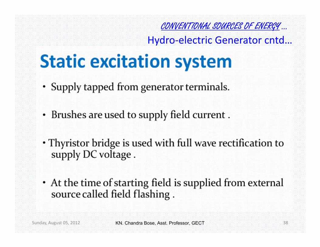
Hydro‐electric Generator cntd…– Recent generators uses static excitation system.
KN. Chandra Bose, Asst. Professor, GECT

CONVENTIONAL SOURCES OF ENERGY …
Sunday, August 05, 2012 34
Hydro‐electric Generator cntd…
KN. Chandra Bose, Asst. Professor, GECT

CONVENTIONAL SOURCES OF ENERGY …
Sunday, August 05, 2012 35
Hydro‐electric Generator cntd…
KN. Chandra Bose, Asst. Professor, GECT

CONVENTIONAL SOURCES OF ENERGY …
Sunday, August 05, 2012 36
Hydro‐electric Generator cntd…
KN. Chandra Bose, Asst. Professor, GECT

CONVENTIONAL SOURCES OF ENERGY …
Sunday, August 05, 2012 37
Hydro‐electric Generator cntd…
KN. Chandra Bose, Asst. Professor, GECT
CONVENTIONAL SOURCES OF ENERGY …
Sunday, August 05, 2012 38
Hydro‐electric Generator cntd…
KN. Chandra Bose, Asst. Professor, GECT

CONVENTIONAL SOURCES OF ENERGY …
Sunday, August 05, 2012 39
Hydro‐electric Generator cntd…
KN. Chandra Bose, Asst. Professor, GECT

CONVENTIONAL SOURCES OF ENERGY …
Sunday, August 05, 2012 40
Hydro‐electric Generator cntd…
KN. Chandra Bose, Asst. Professor, GECT

CONVENTIONAL SOURCES OF ENERGY …
Sunday, August 05, 2012 41
Hydro‐electric Generator cntd…
KN. Chandra Bose, Asst. Professor, GECT

CONVENTIONAL SOURCES OF ENERGY …
Sunday, August 05, 2012 42
KERALA PROJECTS:• KSEB has 23 Hydro Electric Projects, two Diesel power plants and one Wind Farm . The total installed capacity is 2229.6 MW. They are
• Hydro Electric Projects (1940.2MW)– Idukki (780MW)– Sabarigiri (335MW)– Idamalayar (75MW)– Sholayar (54MW)– Pallivasal (37.5MW)– Kuttiyadi (225MW)– Panniar (30MW)– Neriamangalam (77.65MW)– Lower Periyar (180MW)– Poringalkuthu & PLBE (48MW)– Sengulam (48MW)– Kakkad (50MW)
KN. Chandra Bose, Asst. Professor, GECT

CONVENTIONAL SOURCES OF ENERGY …
Sunday, August 05, 2012 43
• Small Hydro Electric Projects(52.85MW)– Kallada (15MW)– Peppara (3MW)– Malankara (10.5MW)– Madupatty (2MW)– Malampuzha (2.5MW)– Lower Meenmutty (3.5MW)– Chembukadavu ‐ 1 (2.7MW)– Chembukadavu ‐ 2 (3.7MW)– Urumi ‐1 (3.75MW)– Urumi ‐2 (2.4MW)– Kuttiyadi Tail Race (3.75MW)
• Thermal Projects (234.6MW)– Brahmapuram Diesel Power Plant (106.6MW)– Kozhikode Diesel Power Plant (128MW)
• Non‐conventional energy (2MW)– Kanjikode Wind Farm (2MW)
KN. Chandra Bose, Asst. Professor, GECT

CONVENTIONAL SOURCES OF ENERGY …
Sunday, August 05, 2012 44
Biggest Kerala project: (An Over view)• The 'Idukki Dam' ‐ Asia's biggest Arch Dam of 555 feet height.
• Between the two mountains ‐ 'Kuravanmala' (839 meters) and 'Kurathimala' (925 meters ).
• Consists of three major dams.• Idukki Dam was commissioned in 1976.• Thickness of 19.81 m, at the deepest foundation & 7.62 m at top.
• Power House is located at Moolamattom which is about 43 kms away from Idukki.
KN. Chandra Bose, Asst. Professor, GECT

CONVENTIONAL SOURCES OF ENERGY …
Sunday, August 05, 2012 45
• A single reservoir spread over 36 miles on a height of 2300 ft. m.s.l.
• falls through a drop of about 669.2 metres(2195 feet) to the underground power.
• The Idukki Project was completed with the economic and technological assistance of Canada in accordance with the Colombo Plan of Commonwealth Countries.
• Turbines, 6 x 130 MW Pelton‐type.• Technically, the dam type is a concrete double, curvature parabolic, thin arc.
KN. Chandra Bose, Asst. Professor, GECT

CONVENTIONAL SOURCES OF ENERGY …
Sunday, August 05, 2012 46
KN. Chandra Bose, Asst. Professor, GECT

CONVENTIONAL SOURCES OF ENERGY …
Sunday, August 05, 2012 47
•
KN. Chandra Bose, Asst. Professor, GECT

CONVENTIONAL SOURCES OF ENERGY …
Sunday, August 05, 2012 48
KN. Chandra Bose, Asst. Professor, GECT

CONVENTIONAL SOURCES OF ENERGY …
Sunday, August 05, 2012 49
KN. Chandra Bose, Asst. Professor, GECT

CONVENTIONAL SOURCES OF ENERGY …
Sunday, August 05, 2012 50
KN. Chandra Bose, Asst. Professor, GECT

CONVENTIONAL SOURCES OF ENERGY …
Sunday, August 05, 2012 51
KN. Chandra Bose, Asst. Professor, GECT

CONVENTIONAL SOURCES OF ENERGY …
Sunday, August 05, 2012 52
Hydro Electric Projects of Kerala under KSEB
• Pallivasal Hydro Electtic Project‐ Dams‐Kandla,Madupetty River‐Palar/Periyar• Sengulam HEP‐ Shengulam Dam River‐Mudriapuzha/Periyar• Neriyamangalam HEP‐ Kallarkutty Dam River‐Mudriapuzha/Periyar• Panniyar HEP‐ Dams‐Ponmudi,Anayirangal Rivers‐ Panniar/Periyar• Idukki HEP‐ Dams‐ Idukki,Cheruthoni,Kulamavu Rivers‐ Periyar, Cheruthoni/Periyar, Kilivillithode• Idukki Augmentation‐ Dams‐ Kallar, Erattayar, Azhutha, Vadakkepuzha, Vazhikkadavu Rivers‐
Perinjankutty/Periyar,Perinjankutty, Periyar..• ldamalayar HEP‐ Idamalayar Dam‐ Rivers‐ldamalayar/Periyar• Lower Periyar HEP‐ Dam‐ Lower Periyar‐ River‐Periyar• Poringalkuttu HEP‐ Dam‐Poringalkuttu‐ River‐ Chalakudy• Sholayar HEP‐ Dams‐ Sholayar‐Main Dam,Sholayar‐Flanking,Sholayar‐ Saddle Dam River‐
Chalakudy• Sabarigiri HEP‐ Dams‐Kakki,Anathodu,Pampa Rivers‐ Kakki/Pamba, Anathodu/Pamba,Pampa• Sabarigiri Augmentation‐ Dams‐ Upper Moozhiyar, Gavi, Kallar, Meenar I,Meenar II Rivers‐
Moozhiyar/Pamba,Gavi Ar/Pamba, Kallar/Pamba, Minar/Pamba, Minar/Pamba• Kakkad HEP‐ Dams‐Veluthodu, Moozhiyar Rivers‐ Veluthodu/Pamba, Moozhiyar/Pamba• Kuttiyadi HEP‐ Dams‐Kuttiyadi River‐Kuttiyadi• Kuttiyadi Augmentation‐ Dams‐ Kuttiyadi Augn, Kosani Saddle,Near Kottagiri Saddle, Kottagiri
Saddle,Kuttiyadi Saddle River‐ Karamanthodu/Kabani
KN. Chandra Bose, Asst. Professor, GECT

CONVENTIONAL SOURCES OF ENERGY …
• Sizes and capacities of hydroelectric facilities
Sunday, August 05, 2012 53
KN. Chandra Bose, Asst. Professor, GECT

CONVENTIONAL SOURCES OF ENERGY …•Major Hydro‐electric
Plants
Sunday, August 05, 2012 54
KN. Chandra Bose, Asst. Professor, GECT

CONVENTIONAL SOURCES OF ENERGY …
Sunday, August 05, 2012 55
Position of Country in hydro‐ generation
KN. Chandra Bose, Asst. Professor, GECT

Sunday, August 05, 2012 56
THERMAL POWER PLANT
KN. Chandra Bose, Asst. Professor, GECT

Thermal ENERGY …
Sunday, August 05, 2012 57
• A thermal power station is a power plant in which the prime mover is steam driven.
• Water is heated, turns into steam and spins a steam turbine which drives an electrical generator.
• After it passes through the turbine, the steam is condensed in a condenser and recycled to where it was heated; this is known as a Rankine cycle.
• The greatest variation in the design of thermal power stations is due to the different fuel sources.
• In India 65% of total power is generated by the Thermal Power Stations.
THERMAL PLANT
KN. Chandra Bose, Asst. Professor, GECT
Thermal ENERGY …
Sunday, August 05, 2012 58
• Almost all coal, nuclear, geothermal, solar thermal electric, and waste incineration plants, as well as many natural gas power plants are thermal.
• Steam power plants may be either condensing or non‐condensing type.
• According to use, plants can be classified into:‐– Industrial power plants or captive power plant.– Central power plants or common plants.
KN. Chandra Bose, Asst. Professor, GECT

Thermal ENERGY …
Sunday, August 05, 2012 59
EFFICIENCY OF STEAM POWER PLANTS• Thermal efficiency of plant is defined as the ratio of the heat equivalent of mechanical energy transmitted to the turbine and heat of combustion (about 30%).
• Over all efficiency is the ratio of heat equivalent of electrical output to the heat of combustion (29%).
Losses in steam plant• a) Boiler house losses
– i) dry flue gases 5%– ii) moisture in gases 5%– iii) ash and unburnt carbon 1%– iv) radiation and leakage 2.5%– v) unknown losses 2.5%
TOTAL 16%
KN. Chandra Bose, Asst. Professor, GECT

Thermal ENERGY …
Sunday, August 05, 2012 60
• b) Turbine losses– Heat rejected to condenser 54%– Alternator losses 01%– Thus out put is 29%
• Thermal efficiency mainly depends on 3 factors –– Pressure– Temperature of the steam entering the turbine– Pressure in the condenser
• Thermal efficiency increase with increase in temp and pressure of steam entering the turbine.
KN. Chandra Bose, Asst. Professor, GECT

Thermal ENERGY …
Sunday, August 05, 2012 61
• Which effectively increased by decreasing the pressure in the condenser and usually kept very low at 0.04kg/cm2.
• It can also increased by re‐heating the steam.
Classification• Classified by the type of fuel and the type of prime mover
installed.– By fuel
• Fossil‐fuel power stations• Nuclear power plants• Geothermal power• Biomass‐fuelled power plants• In integrated steel mills, blast furnace exhaust gas is a low‐cost, fuel.• Waste heat from industrial processes is occasionally concentrated enough to use for power generation.
• Solar thermal.
KN. Chandra Bose, Asst. Professor, GECT

Thermal ENERGY …
Sunday, August 05, 2012 62
– By prime mover• Steam turbine• Gas turbine• Combined cycle• Internal combustion reciprocating engines• Microturbines, Stirling engine
KN. Chandra Bose, Asst. Professor, GECT

Thermal ENERGY …
Sunday, August 05, 2012 63
• Factors to be considered– Nearness to the load Centre– Supply of water– Availability of coal– Land requirement– Type of land– Transportation facilities– Labour supplies– Ash disposal– Distance from polluted area
Selection of site for steam power plants
KN. Chandra Bose, Asst. Professor, GECT
Thermal ENERGY …
Sunday, August 05, 2012 64
• 1. Load centre: ‐– Plant should be as near as possible to the load centre so that the transmission cost and losses are minimum.
• 2. Supply of water: ‐ Large amount of water is required • to raise the steam in the boiler • for cooling purpose• As carrying medium for ash disposal• Drinking purpose.
– In plants approximately 1.26x10⁶ k cals of heat per MW per Hour has to be disposed off in the condenser.
– In direct circulation from source of water, 120m3 of water is required per MW per hour.
KN. Chandra Bose, Asst. Professor, GECT

Thermal ENERGY …
Sunday, August 05, 2012 65
– Efficiency of direct cooled plant is 0.5% higher than that of plant cooled by cooling towers.
– Hence saving is Rs.7.5lacs per year in fuel cost for a 2000MW station.
– Hence plant should be located near sea, river or lake.
• 3. availability of coal: ‐– huge amount of coal is required for raising steam – 20,000 tonnes per day for a 2000MW station.
– Govt. policy is to use only low grade coal with 30 to 40% ash content for power generation.
• 4. Land requirement:– For coal storage, cottage, and ash disposal etc.– For a 2000MW plant, around 200 to 250 acres land is required.– Consider future expansion while selecting land.
KN. Chandra Bose, Asst. Professor, GECT

Thermal ENERGY …
Sunday, August 05, 2012 66
• 5. Type of land:– Should be of good bearing capacity.– Over all load may come around 7kg per cm2
– Reasonably plain land is suitable.
• 6. Transportation• 7. Labour supplies: ‐ skilled and un‐skilled• 8. Ash disposal:
– Main waste from plant is ash which may come around 3.5 tonnesper day.
– It may be used for building purpose or brick making.
KN. Chandra Bose, Asst. Professor, GECT

Thermal ENERGY …
Sunday, August 05, 2012 67
WORKING OF STEAM PLANT
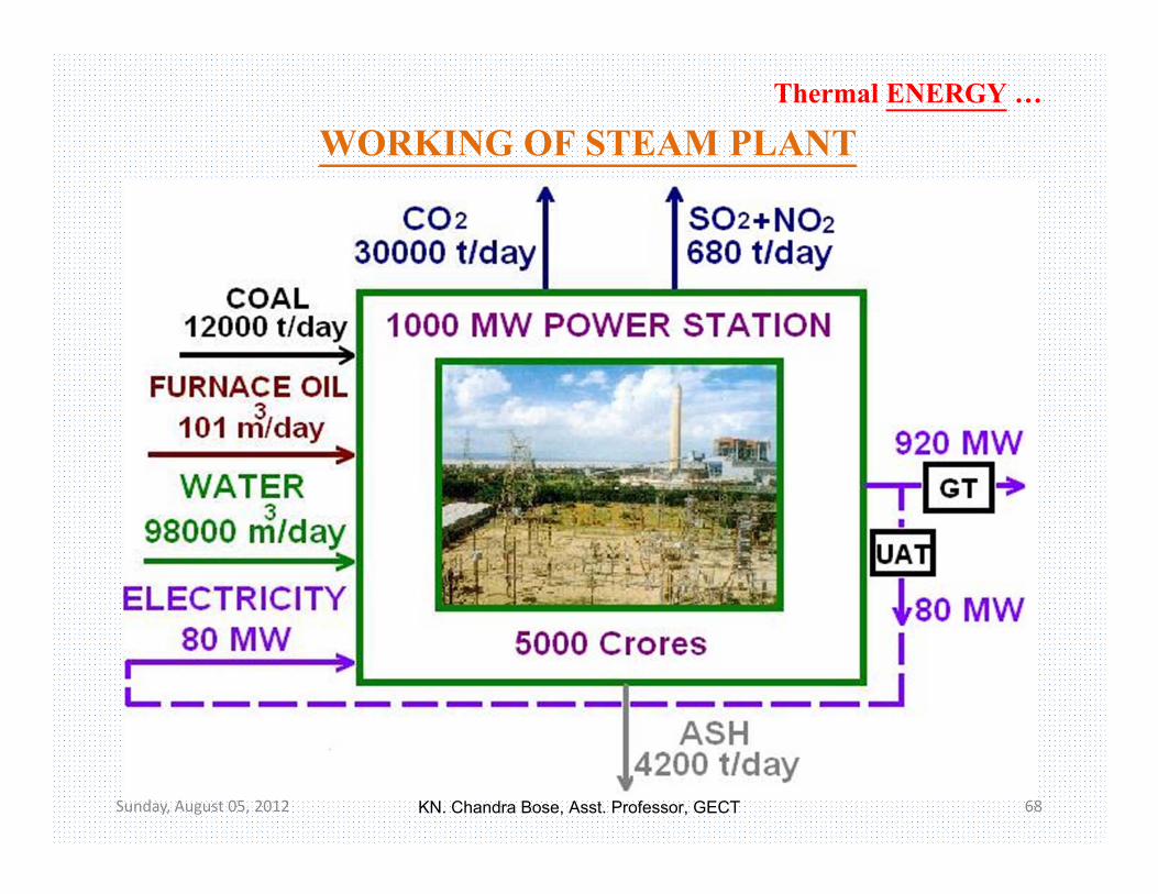
• A coal based thermal power plant converts the chemical energy of the coal into electrical energy.
• Achieved by raising the steam in the boilers, expanding it through the turbine and coupling the turbines to the generators which converts mechanical energy into electrical energy.
• Steam after expansion, condensed and fed into boiler again.
• Coal based thermal power plant works on the principal of Modified Rankine Cycle.
KN. Chandra Bose, Asst. Professor, GECT
Thermal ENERGY …
Sunday, August 05, 2012 68
WORKING OF STEAM PLANT
KN. Chandra Bose, Asst. Professor, GECT

Thermal ENERGY …
Sunday, August 05, 2012 69
WORKING OF STEAM PLANT
KN. Chandra Bose, Asst. Professor, GECT

Thermal ENERGY …
Sunday, August 05, 2012 70
WORKING OF STEAM PLANT
KN. Chandra Bose, Asst. Professor, GECT

Thermal ENERGY …
Sunday, August 05, 2012 71
• A deaerator is a device used for the removal of oxygen and other dissolved gases from the feedwater.
• Dissolved oxygen in boiler feed water will cause serious corrosion, damages the steam systems by attaching to the walls of metal piping and other metallic equipment and forming oxides (rust).
• Dissolved carbon dioxide combines with water to form carbonic acidthat causes further corrosion.
• Most deaerators are designed to remove oxygen down to levels of 7 ppb by weight (0.005 cm³/L) or less as well as essentially eliminating carbon dioxide.
• Types of deaerators:‐ the tray‐type and the spray‐type:• The tray‐type (also called the cascade‐type) includes a vertical
domed deaeration section mounted on top of a horizontal cylindrical vessel which serves as the deaerated boiler feedwaterstorage tank.
• The spray‐type consists only of a horizontal (or vertical) cylindrical vessel which serves as both the deaeration section and the boiler feedwater storage tank.
KN. Chandra Bose, Asst. Professor, GECT

Thermal ENERGY …
Sunday, August 05, 2012 72
KN. Chandra Bose, Asst. Professor, GECT

Thermal ENERGY …
Sunday, August 05, 2012 73
Components of Coal Fired Thermal Power Station:Coal Preparation• i)Fuel preparation system:
– The raw feed coal from the coal storage area is first crushed into small pieces and then conveyed to the coal feed hoppers at the boilers.
– The coal is next pulverized into a very fine powder, so that coal will undergo complete combustion during combustion process.
• ii)Dryers:
– Used in order to remove the excess moisture from coal.– presence of moisture will result in fall in efficiency due to incomplete combustion and also result in CO emission.
KN. Chandra Bose, Asst. Professor, GECT
Thermal ENERGY …
Sunday, August 05, 2012 74
• iii)Magnetic separators:– coal may contain iron particles. These iron particles may result in wear and tear.
– so they are removed with the help of magnetic separators.– The coal finally transferred to the storage site.– There are two types of storage:
– 1. Live Storage(boiler room storage):• This storage consists of about 24 to 30 hrs. of coal requirements of the plant.
• The live storage can be provided with bunkers & coal bins. • Bunkers are enough capacity to store the requisite of coal. From bunkers coal is transferred to the boiler grates.
KN. Chandra Bose, Asst. Professor, GECT

Thermal ENERGY …
Sunday, August 05, 2012 75
– 2. Dead storage‐• stored for future use. • Mainly it is for longer period of time• It is also mandatory to keep a backup of fuel for specified amount of days depending on the reputation of the company.
Forms of storages are :–• Stacking the coal in heaps over available open ground areas.• Under cover or alternatively in bunkers.• Allocating special areas & surrounding these with high reinforced concerted retaking walls.
• A Boiler or steam generator essentially is a container into which water can be fed and steam can be taken out at desired pressure, temperature and flow.
Boiler and auxiliaries
KN. Chandra Bose, Asst. Professor, GECT

Thermal ENERGY …
Sunday, August 05, 2012 76
• The boiler should have a facility to burn a fuel and release the heat. The functions of a boiler:‐
– 1. To convert chemical energy of the fuel into heat energy.– 2. To transfer this heat energy to water for evaporation as well to steam for superheating.
The basic components of Boiler are: ‐• Furnace and Burners :‐ A furnace is a device used for heating.• Steam and Superheating• Bolilers are classified as:
1. Fire tube boilers : – In fire tube boilers, hot gases are passed through the tubes and water surrounds these tubes.
– Simple, compact and rugged in construction. – Depending on whether the tubes are vertical or horizontal these are further classified as vertical and horizontal tube boilers.
KN. Chandra Bose, Asst. Professor, GECT

Sunday, August 05, 2012 77
– In this since the water volume is more, circulation will be poor.– So they can't meet quickly the changes in steam demand.– High pressures of steam are not possible,– Maximum pressure that can be attained is about 17.5kg/cm2. – Due to large quantity of water in the drain it requires more time for steam raising.
2. Water tube boilers : – Here Water is inside the tubes and hot gases are outside the tubes.
– Hot gases which surrounds these tubes will convert the water in tubes in to steam.
– Attain pressure as high as 125 kg/sq cm and temperatures from 315 to 575 centigrade.
KN. Chandra Bose, Asst. Professor, GECT

Sunday, August 05, 2012 78
• Superheater : – A device which removes the last traces of moisture from the saturated steam leaving the boiler tubes and also heated above its saturation temperature.
– The superheater may consist of one or more stages of tube banks arranged to effectively transfer heat from the products of combustion.
– Carbon steel – upto 950oF, stainless steel – 1200oF– Superheaters are classified as convection , radiant or combination of these.
Reheater : – Reheater is also steam boiler component in which heat is added to the intermediate‐pressure steam.
– The steam after reheating is used to rotate the second steam turbine
KN. Chandra Bose, Asst. Professor, GECT

Sunday, August 05, 2012 79
Condenser : – Steam after passing through turbine comes to condenser.– Condenser refers to the shell and tube heat exchanger installed at the outlet of every steam turbine.
– These are heat exchangers which convert steam from its gaseous to its liquid state.
– Condensers are classified as (i) Jet condensers or contact condensers (ii) Surface condensers.
Cooling Towers :– The condensate (water) formed in the condenser after condensation is initially at high temperature.
– It is a tower‐ or building‐like device in which atmospheric air circulates in direct or indirect contact with warmer water.
KN. Chandra Bose, Asst. Professor, GECT

Sunday, August 05, 2012 80
Economiser :– Flue gases coming out of the boiler carry lot of heat.– Function of economiser is to recover some of the heat from the heat carried away in the flue gases up the chimney and utilize for heating the feed water to the boiler.
– Placed in the passage of flue gases in between the exit from the boiler and the entry to the chimney.
– The use of economiser results in saving in coal consumption , increase in steaming rate and high boiler efficiency by 10 – 12%.
Prime Movers:– Converts steam energy into mechanical energy.– Reciprocating type or turbines, (common is turbines).
– Turbines gives high speed.
KN. Chandra Bose, Asst. Professor, GECT

Sunday, August 05, 2012 81
Steam turbines:– There is no pistons, slide valves and no fly wheels.– Classified into impulse and reaction type Turbine.
• In an Impulse turbine, steam expands in stationary nozzles and there is no pressure drop over the blades or runner.
• Has high speed and ample clearance between runner and stationary blades.
• In a reaction turbine, the steam does not expands in nozzle but expands as flows over the blades.
• They are of low speed.
Control room:– Houses all necessary measuring instruments for each panel.
– Separate battery room and a motor generator set or a rectifier is installed for control circuit.
KN. Chandra Bose, Asst. Professor, GECT

Sunday, August 05, 2012 82
KN. Chandra Bose, Asst. Professor, GECT

Sunday, August 05, 2012 83
Advantages:• The fuel used is quite cheap.• Less initial cost as compared to other generating plants.• It can be installed at any place irrespective of the existence of coal. • It require less space as compared to Hydro power plants.• Cost of generation is less than that of diesel power plants.• Suitable for rapidly changing loads and can operate under 25% over load
continuously.
Disadvantages:• It pollutes the atmosphere due to production of large amount of
smoke and fumes.• It is costlier in running cost as compared to Hydro electric plants.• Requires huge amount of water.
Merits and Demerits of Steam Plant
KN. Chandra Bose, Asst. Professor, GECT

Sunday, August 05, 2012 84
Diesel oil is used as fuel. Diesel plants are uneconomical owing to oil cost. Commonly installed, where other sources of fuel is not available.
Selection of site: Distance from load centre Availability of land Availability of fuel Transportation facility Availability of water Distance from populated area Types of land
Diesel Electric Power Plant
KN. Chandra Bose, Asst. Professor, GECT

Sunday, August 05, 2012 85
Diesel Engine Air filter and Supercharger : Exhaust system : Fuel System : Cooling System : Starting System : Governing System : Diesel Engine Generator :
Diesel Electric Power Plant
Elements of Plant
KN. Chandra Bose, Asst. Professor, GECT

Sunday, August 05, 2012 86
Diesel Engine : which develops power. They may be 4 strokes or 2 stroke engine. 4 stroke engines has lower fuel consumption, more flexibility, better
scavenging and higher efficiency than 2 stroke. Cylinders are arranged in V shape to make the engine more
compact. 6 to 8 cylinders are commonly used. Speed is in the range of 500‐1000 rpm. The diesel engines are compression ignition type. Diesel engines are available in sizes from 75kW to 3750kW.
Diesel Electric Power Plant
KN. Chandra Bose, Asst. Professor, GECT

Sunday, August 05, 2012 87
Air filter and Supercharger : The function of air filter is to remove the dust from the air. The function of supercharger is to increase the pressure of air
supplied to the engine to increase the power of the engine. The supercharger is driven by the engine.
Exhaust system : This includes silencer and connecting ducts. silencer is required in between the engine and the intake system. The temperature of exhaust gases are really high. Which can be used for heating the oil or air supplied to the engine.
Diesel Electric Power Plant
KN. Chandra Bose, Asst. Professor, GECT

Sunday, August 05, 2012 88
Fuel System : This includes fuel storage tank, fuel pump, fuel transfer pump,
strainers and heaters. The fuel is supplied according to the load on the plant. Strainers are provided to remove the suspended impurities. Heaters are required to heat the oil, especially during winter
seasons.
Cooling System : Includes oil pumps, oil tanks, filters, coolers and connecting pipes. The function of the lubricating system is to reduce the friction of
moving parts and to reduce the wear and tear of the engine parts. The life of engine and its efficiency largely depends on the
lubricating system.
Diesel Electric Power Plant
KN. Chandra Bose, Asst. Professor, GECT

Sunday, August 05, 2012 89
Starting System : Includes compressed air tanks. Function is to start the engine from cold by supplying the compressed air.
Governing System : Their function is to maintain the speed of the engine constant irrespective
of load on the plant. Done by varying fuel supply to the engine according to load.
Diesel Engine Generator : The generators is of rotating field, salient pole construction, speed
ranging from 214 to 1000 rpm. Capacities ranging from 25‐5000 kVA at 0.8 power factor lagging. Generators are coupled directly to diesel engine. Provided with voltage regulators to allow voltage regulation. Excitation is usually at 115 to 230 V from a DC exciter, usually coupled to
the engine shaft through a belt.
Diesel Electric Power Plant
KN. Chandra Bose, Asst. Professor, GECT

Sunday, August 05, 2012 90
• The only purpose of a nuclear power plant is to produce electricity.
• Power plant needs a source of heat to boil the water which becomes steam and turbine turns an electrical generator.
• In a nuclear plant the source of heat is a nuclear reactor.• Fuel for a nuclear reactor is uranium, but not just any
uranium.• Most uranium atoms (99.3%) consist of a nucleus with 146
uncharged neutrons and 92 positively charged protons.• Adding the number of neutrons and protons, these atoms
have a total of 238 neutrons and protons.
NUCLEAR POWER PLANT
KN. Chandra Bose, Asst. Professor, GECT

HOW IT WORKS??
However, not all uranium atoms have 146 neutrons; 0.7% have 143, so this is called U‐235.
The most important difference is that U‐235 spontaneously splits, producing two smaller nuclei plus 2 to 5 neutrons.
KN. Chandra Bose, Asst. Professor, GECT
Sunday, August 05, 2012 92
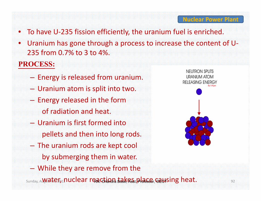
• To have U‐235 fission efficiently, the uranium fuel is enriched.• Uranium has gone through a process to increase the content of U‐
235 from 0.7% to 3 to 4%. PROCESS:
– Energy is released from uranium.– Uranium atom is split into two.– Energy released in the form
of radiation and heat. – Uranium is first formed into
pellets and then into long rods. – The uranium rods are kept cool
by submerging them in water. – While they are remove from the
water, nuclear reaction takes place causing heat.
Nuclear Power Plant
KN. Chandra Bose, Asst. Professor, GECT

Sunday, August 05, 2012 93
The amount of heat required is controlled by raising and lowering the rods.
If more heat is required the rods are raised further out of the water and if less is needed they lower further into it.
The most common nuclear fuels are 235U and 239Pu.
Nuclear Power Plant
KN. Chandra Bose, Asst. Professor, GECT

Sunday, August 05, 2012 94
Nuclear Power Plant
• • U235 + n → fission + 2 or 3 n + 200 MeV
If each neutron releases two or more neutrons, then the
number of fissions doubles in each generation.
In that case, in 10th generations there are 1,024 fissions
and in 80 generations about 6 x 10 23 (a mole) fissions.
KN. Chandra Bose, Asst. Professor, GECT

Sunday, August 05, 2012 95
PLANT LAYOUT
Nuclear Power Plant
KN. Chandra Bose, Asst. Professor, GECT

TYPES OF NUCLEAR RECATORBOILING WATER
REACTORPRESSURIZED WATER
REACTOR
KN. Chandra Bose, Asst. Professor, GECT

PRESSURIZED WATER REACTOR
KN. Chandra Bose, Asst. Professor, GECT

BOILING WATER REACTOR
KN. Chandra Bose, Asst. Professor, GECT

Sunday, August 05, 2012 99
Nuclear Power Plant
NUCLEAR REACTOR
A nuclear reactor is a device in which nuclear chain reactions are
initiated, controlled, and sustained at a steady rate.CONTROL RODS Control rods absorbs neutron's.
The control rods essentially contain neutron absorbers like,
boron, cadmium or indium.STEAM GENERATORS Convert water into steam from heat produced in reactor core.
Either ordinary water or heavy water is used as the coolant.
KN. Chandra Bose, Asst. Professor, GECT

Sunday, August 05, 2012 100
STEAM TURBINE
Extracts thermal energy from pressurized steam, and converts it
into useful mechanical power.
Various high‐performance alloys and super alloys have been used
for steam generator turbine.
COOLANT PUMP
The coolant pump pressurizes the coolant to155bar.
The pressure of the coolant loop is maintained almost constant.
Nuclear Power Plant
KN. Chandra Bose, Asst. Professor, GECT

Sunday, August 05, 2012 101
FEED PUMP
Steam coming out of the turbine, flows through the condenser for
condensation and recirculate for the next cycle of operation.
The feed pump circulates the condensed water in the working fluid loop.
CONDENSER
Used to condense vapour into liquid.
The objective of the condenser are to reduce the turbine exhaust
pressure.
Which increases the efficiency and to recover high quality feed water in
the form of condensate & feed back it to the steam generator without
any further treatment.
Nuclear Power Plant
KN. Chandra Bose, Asst. Professor, GECT

Sunday, August 05, 2012 102
COOLING TOWER
Transfer process waste heat to the atmosphere.
Water circulating through condenser is taken to the cooling tower
for cooling and reuse.
Nuclear Power Plant
KN. Chandra Bose, Asst. Professor, GECT
Sunday, August 05, 2012 103
ADVANTAGES
Fission is the most energy efficient process.
Nuclear power generation does emit relatively low amounts of
carbon dioxide (CO2).
The emissions of green house gases (global warming) relatively
little.
It is possible to generate a high amount of electrical energy.
Nuclear Power Plant
KN. Chandra Bose, Asst. Professor, GECT

Sunday, August 05, 2012 104
DISADVANTAGES
The problem of radioactive waste is still an unsolved one.
High risks: It is technically impossible to build a plant with 100%
security.
Uranium is a scarce resource, its supply is estimated to last only for
the next 30 to 60 years depending on the actual demand.
Nuclear Power Plant
KN. Chandra Bose, Asst. Professor, GECT

Sunday, August 05, 2012 105
DISADVANTAGES
Nuclear power plants as well as nuclear waste could be preferred
targets for terrorist attacks.
During operation radioactive waste is produced, which in turn can
be used for the production of nuclear weapons.
Nuclear Power Plant
KN. Chandra Bose, Asst. Professor, GECT

Indian Nuclear Program: The Constraints
• Uranium ore reserves only for 10,000MW for 40 years• Slow growth of nuclear electric power: ~1000 MW
annually• Major dependence on Pu and U233. • Complex fuel technologies. Total capacity limited
Nuclear Power Plant
KN. Chandra Bose, Asst. Professor, GECT

Nuclear Power: The Present Status
0
2000
4000
6000
8000
10000
12000
14000
1969 1973 1981 1984 1986 1991 1992 1993 1995 2000 2005 2006 2015
Inst
alle
d C
apac
ity (M
W)
Planned
Presently installed
Nuclear Power Plant
KN. Chandra Bose, Asst. Professor, GECT
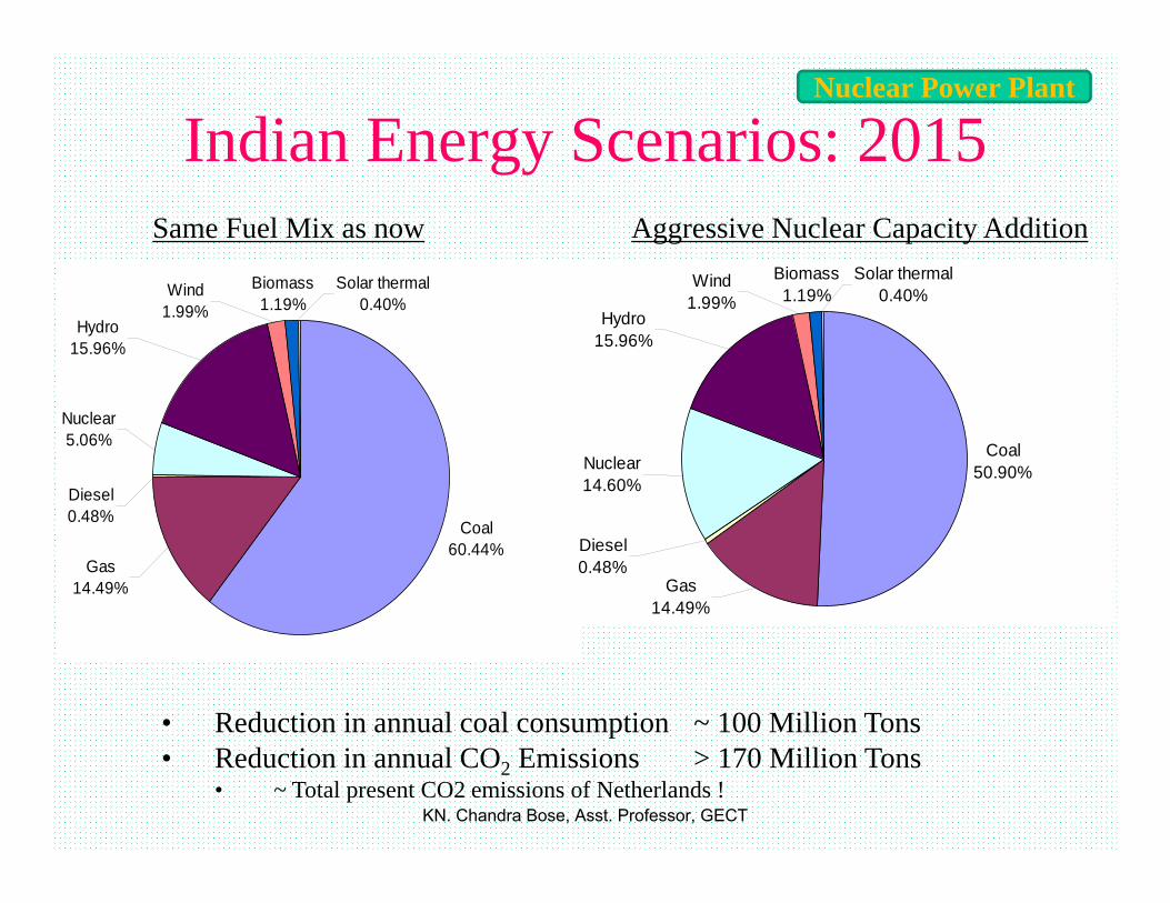
Indian Energy Scenarios: 2015
Coal60.44%
Gas14.49%
Diesel0.48%
Nuclear5.06%
Hydro15.96%
Solar thermal0.40%
Biomass1.19%
Wind1.99%
Gas14.49%
Diesel0.48%
Nuclear14.60%
Hydro15.96%
Solar thermal0.40%
Biomass1.19%
Wind1.99%
Coal50.90%
Same Fuel Mix as now Aggressive Nuclear Capacity Addition
• Reduction in annual coal consumption ~ 100 Million Tons• Reduction in annual CO2 Emissions > 170 Million Tons
• ~ Total present CO2 emissions of Netherlands !
Nuclear Power Plant
KN. Chandra Bose, Asst. Professor, GECT

Sunday, August 05, 2012 109
Renewable energy
The Ultimate Renewable Resources
KN. Chandra Bose, Asst. Professor, GECT

Sunday, August 05, 2012 110
A renewable resource is a natural resource with the ability to reproduce through biological or natural processes and replenished with the passage of time.
Renewable resources are part of our natural environment and form our eco‐system.
Energy generated by using
windTidesSolargeothermal heatbiomass including farm and animal waste as well as human excreta.
Renewable energy
KN. Chandra Bose, Asst. Professor, GECT

All renewable energy, ultimately comes from the sun. The earth receives 1.74 x 10¹⁷ watts of power (per hour) from the
sun. About one or 2 percent of this energy is converted to wind energy.
Sunday, August 05, 2012 111
WIND POWER Renewable energy
KN. Chandra Bose, Asst. Professor, GECT

Sunday, August 05, 2012 112
Working: The terms wind energy or wind power describe the process by which the wind is used to generate mechanical power or electricity.
Wind turbines convert the kinetic energy in the wind into mechanical power.
Gross wind power potential of India is estimated to be about 20,000 MW, wind power projects of 970 MW capacities were installedtill March. 1998
Renewable energy
KN. Chandra Bose, Asst. Professor, GECT

Sunday, August 05, 2012 113
Consists of three crucial parts: Rotor blades –
When the wind forces the blades to move, it has transferred some of its energy to the rotor.
Shaft – Shaft is connected to the center of the rotor. When the rotor spins, the rotor transfers its mechanical, rotational energy to
the shaft. High‐speed shaft: Drives the generator. Low‐speed shaft: The rotor turns the low‐speed shaft at about 30 to 60
rotations per minute. Generator• Anemometer:
– Measures the wind speed and transmits wind speed data to the controller.
• Brake:– A disc brake, which can be applied mechanically, electrically, or hydraulically to stop the rotor in emergencies.
Parts of Wind TurbinesRenewable energy
KN. Chandra Bose, Asst. Professor, GECT

Sunday, August 05, 2012 114
• Controller:– The controller starts up the machine at wind speeds of about 8 to 16 miles per hour (mph) and shuts off the machine at about 55 mph.
– Turbines do not operate at wind speeds above about 55 mph because they might be damaged by the high winds.
• Gear box:– Gears connect the low‐speed shaft to the high‐speed shaft and increase the rotational speeds from about 30 to 60 rotations per minute (rpm) to about 1000 to 1800 rpm.
• Nacelle:– The nacelle sits at top of the tower and contains the gear box, low‐ and high‐speed shafts, generator, controller, and brake. Some nacelles are large enough for a helicopter to land on.
Renewable energy
KN. Chandra Bose, Asst. Professor, GECT

Sunday, August 05, 2012 115
Pitch:– Blades are turned, or pitched, out of the wind to control the rotor speed and keep the rotor from turning in winds that are too high or too low to produce electricity.
Rotor:– The blades and the hub together are called the rotor.
Tower:– Towers are made from tubular steel, concrete, or steel lattice. – Because wind speed increases with height, taller towers enable turbines to capture more energy and generate more electricity.
Wind direction:– This is an “upwind” turbine, so‐called because it operates facing into the wind.
Renewable energy
KN. Chandra Bose, Asst. Professor, GECT

Sunday, August 05, 2012 116
Wind vane:– Measures wind direction and communicates with the yaw drive to orient the turbine properly with respect to the wind.
Yaw drive:– Used to keep the rotor facing into the wind as the wind direction changes
Yaw motor:– Powers the yaw drive.
Renewable energy
KN. Chandra Bose, Asst. Professor, GECT

Sunday, August 05, 2012 117
Wind power– The power in the wind is proportional to:• the area of windmill being swept by the wind• the cube of the wind speed• the air density – which varies with altitude
– The formula:Power =½(density of air x swept area x velocity cubed)P = ½.ρ.A.V3
where, P is power in watts (W)ρ is the air density in (kg/m3)A is the swept rotor area in (m2)V is the wind speed in (m/s)
Renewable energy
KN. Chandra Bose, Asst. Professor, GECT

Sunday, August 05, 2012 118
Mean wind speed is from, 6 to 10 m/s.Renewable energy
KN. Chandra Bose, Asst. Professor, GECT

Sunday, August 05, 2012 119
It is a renewable source of energy.Wind power systems are non‐polluting.Wind energy systems avoid fuel provision and transport.On a small scale up to a few kilowatt, system is small.
Wind energy available is fluctuating in nature.Wind energy needs storage capacity because of its irregularities.
Wind energy systems are noisy in operation.Wind power systems have a relatively high overall weight.
ADVANTAGES OF WIND ENERGY
DISADVANTAGES OF WIND ENERGY
Renewable energy
KN. Chandra Bose, Asst. Professor, GECT

Sunday, August 05, 2012 120
What is Tidal Energy?– Tidal energy is the utilization of the variations in sea level caused primarily by the gravitational effects of the moon, combined with the rotation of the Earth.
• Tides generated by the combination of the moon and sun’s gravitational forces
• Greatest affect in spring when moon and sun combine forces• Bays and inlets amplify the height of the tide• For energy production, the height difference needs to be at least 5
meters. India possesses 8000‐9000 MW of tidal energy potential.
Tidal EnergyRenewable energy
KN. Chandra Bose, Asst. Professor, GECT

Sunday, August 05, 2012 121
• Tidal EnergyRenewable energy
KN. Chandra Bose, Asst. Professor, GECT

Sunday, August 05, 2012 122
• Two types of tidal plant facilities.– Tidal barrages– Tidal current turbines
• Ideal sites are located at narrow channels and experience high variation in high and low tides.
Renewable energy
KN. Chandra Bose, Asst. Professor, GECT

Tidal Barrage •Two types:• Single basin system-
Ebb generation: During flood tide basin is filled and sluice gates are closed , trapping water. Gates are kept closed until the tide has ebbed sufficiently and thus turbines start spinning and generating electricity.Flood generation: The basin is filled through the turbine which generate at flood tide.Two way generation: Sluice gates and turbines are closed until near the end of the flood tide when water is allowed to flow through the turbines into the basin creating electricity. At the point where the hydrostatic head is insufficient for power generation the sluice gates are opened and kept open until high tide when they are closed. When the tide outside the barrage has dropped sufficiently water is allowed to flow out of the basin through the turbines again creating electricity.
Double-basin system: There are two basins, but it operates similar to en ebb generation, single-basin system. The only difference is a proportion of the electricity is used to pump water into the second basin allowing storage.
• Utilize potential energy• Tidal barrages are typically dams built
across an estuary or bay. • consist of turbines, sluice gates,
embankments, and ship locks.
Basin
KN. Chandra Bose, Asst. Professor, GECT

Tidal current turbines• Extracts kinetic energy from
moving water generated by tides.• Operate during flood and ebb
tides.• Consists of a rotor, gearbox, and
a generator. These three parts are mounted onto a support structure. There are three main types:▫ Gravity structure▫ Piled structure▫ Floating structure
KN. Chandra Bose, Asst. Professor, GECT

-Advantages and Disadvantages-• Advantages
– The energy is free – no fuel needed, no waste produced
– Not expensive to operate and maintain– Can produce a great deal of energy
• Disadvantages– Depends on the waves – sometimes you’ll get
loads of energy, sometimes almost nothing– Needs a suitable site, where waves are
consistently strong– Some designs are noisy. But then again, so are
waves, so any noise is unlikely to be a problem– Must be able to withstand
KN. Chandra Bose, Asst. Professor, GECT

-Environmental Impact-– Noise pollution– Displace productive fishing sites– Change the pattern of beach sand
nourishment– Alter food chains and disrupt migration
patterns– Offshore devices will displace bottom-
dwelling organisms.
KN. Chandra Bose, Asst. Professor, GECT

Sunday, August 05, 2012 127
What is Solar Energy?
Originates with the thermonuclear fusion reactions occurring inthe sun.
Represents the entire electromagnetic radiation(visible light, infrared, ultraviolet, x‐rays, and radio waves).
Renewable energySolar Energy
KN. Chandra Bose, Asst. Professor, GECT

Sunday, August 05, 2012 128
How much solar energy?
The surface receives about 47% of the total solar energy. Sun radiates energy of 3.5x10²³kW into space and only 2x10¹⁴kW reaches the earth.
Photovoltaic cells are capable of directly converting sunlight into electricity.
A simple silicon Wafer converts light energy into Voltage.
Produced based on types of silicon (n‐ and p‐types)used for the layers. Each cell=0.5 volts.
Renewable energy
KN. Chandra Bose, Asst. Professor, GECT

Sunday, August 05, 2012 129
• Battery needed as storage.• No moving partsdo not wear out.• Because they are exposed to the weather, their lifespan is about 20 years.
India gets more than 5,000 trillion kWh of Solar Energy every year.
Solar Energy is successfully used in residential and industrial settings for cooking, heating, cooling, lighting, space technology, and for communications among other uses.
Solar panels are one of the most important factors in the generation of Solar Energy.
On an average, 1 Sq. Ft. of Solar Panel generates 10.6 W of power.
Renewable energy
KN. Chandra Bose, Asst. Professor, GECT

Sunday, August 05, 2012 130
Efficiency of cells is up to 23%/ improving. Solar collectors are of mainly two types‐ Flat plate collectors Focussing or concentrating collectors. Cylindrical parabolic concentrators Paraboloids, mirror arrays
Renewable energy
KN. Chandra Bose, Asst. Professor, GECT

Sunday, August 05, 2012 131
Renewable energy
KN. Chandra Bose, Asst. Professor, GECT

Sunday, August 05, 2012 132
Different Arrangements of Plant Renewable energy
KN. Chandra Bose, Asst. Professor, GECT

Sunday, August 05, 2012 133
Geo‐Thermal Energy:• Geo‐thermal energy is the heat of the earth's interior. This energy is manifested in the hot springs.
• India is not very rich in this source.Energy from Biomass:• Biomass refers to all plant material and animal excreta when considered as an energy source.
• Some important kinds of biomass are inferior wood, urban waste, farm animal and human waste.
Renewable energy
KN. Chandra Bose, Asst. Professor, GECT

Sunday, August 05, 2012 134
Renewable energy
KN. Chandra Bose, Asst. Professor, GECT

Sunday, August 05, 2012 135
Renewable energy
KN. Chandra Bose, Asst. Professor, GECT

Sunday, August 05, 2012 136
Advantages of Geothermal Energy• Significant Cost Saving : • Environmental Benefits :.• Direct Use : • Job Creation and Economic Benefits : Disadvantages of Geothermal Energy• Not Widespread Source of Energy :• High Installation Costs : Can Run Out Of Steam Suited To Particular Region May Release Harmful Gases :
Renewable energy
KN. Chandra Bose, Asst. Professor, GECT

Sunday, August 05, 2012 137
The field of MHD was initiated by Hannes Alfvén , for which he received the Nobel Prize in Physics in 1970.
Magneto hydrodynamics (MHD) (magneto fluid dynamics or hydro magnetics) is the academic discipline which studies the dynamics of electrically conducting fluids.
Examples of such fluids include plasmas, liquid metals, and salt water.
Renewable energyMAGNETO HYDRO DYNAMIC POWER GENERATION (MHD )
KN. Chandra Bose, Asst. Professor, GECT

Sunday, August 05, 2012 138
MHD power generation is a new system of electric power generation which is said to be of high efficiency and low pollution.
In advanced countries MHD generators are widely used but in developing countries like INDIA, it is still under construction.
An MHD generator is a device for converting heat energy of a fuel directly into electrical energy without conventional electric generator.
Renewable energy
KN. Chandra Bose, Asst. Professor, GECT

Sunday, August 05, 2012 139
• Conventional Gen: ‐ conductor moves across a magnetic field, a voltage is induced in it.
• In MHD generator, the solid conductors are replaced by a gaseous conductor, an ionized gas.
• If such a gas is passed at a high velocity through a powerful magnetic field, a current is generated and can be extracted by placing electrodes in suitable position in the stream.
Renewable energyPRINCIPLES OF MHD POWER GENERATION
KN. Chandra Bose, Asst. Professor, GECT

Sunday, August 05, 2012 140
Renewable energy
KN. Chandra Bose, Asst. Professor, GECT

Sunday, August 05, 2012 141
• The flow direction is right angles to the magnetic fields direction.
• An electromotive force (or electric voltage) is induced in the direction at right angles to both flow and field directions.
Renewable energy
KN. Chandra Bose, Asst. Professor, GECT

Sunday, August 05, 2012 142
The conducting flow fluid is forced between the plates with a kinetic energy and pressure differential sufficient to over come the magnetic induction force Find.
Ionization is produced either by thermal means. The atoms of seed element split off electrons. The presence of the negatively charged electrons makes the gas an electrical conductor.
Renewable energy
KN. Chandra Bose, Asst. Professor, GECT

Sunday, August 05, 2012 143
The conversion efficiency is around 50%. Still higher efficiencies are expected in future, around 60 –65%.
• Large amount of power is generated.• It has no moving parts, so more reliable.• The closed cycle system produces power, free of pollution.• It has ability to reach the full power level as soon as started.
It is possible to use MHD for peak power generations and emergency service.
Renewable energyADVANTAGES
KN. Chandra Bose, Asst. Professor, GECT

Economics of Power Generation• The function of a power station is to deliver power at the lowest possible cost per kilo watt hour.(Practically not possible, explained by Economics of power Generation).
• The total cost is made up of fixed and operating cost.– Fixed cost consists:‐
• interest on the capital, • taxes, insurance, depreciation• salary of managerial staff
– operating expenses• cost of fuels, water, oil, labor, repairs and maintenance etc.
Sunday, August 05, 2012 144
KN. Chandra Bose, Asst. Professor, GECT

Sunday, August 05, 2012 145
The cost of power generation can be minimized by :
1. Selecting equipment of longer life and proper capacities.
2. Running the station at high load factor.3. Operation through fewer men.4. Increasing the efficiency of plant.5. Proper maintenance in time.6. Keep efficient supervisors.7. Using a plant of simple design that does not need highly skilled personnel.
KN. Chandra Bose, Asst. Professor, GECT

Sunday, August 05, 2012 146
Hence plant selection can be based on fixed and operating cost. For nuclear plant fuel cost is relatively low and fixed, operating, maintenance charges are high. For diesel, fuel cost is high For hydro, fixed charges are high (70 to 80%). Hence generation must be regulated according to demand and plant should run at full load at which they give max.η.
KN. Chandra Bose, Asst. Professor, GECT

Sunday, August 05, 2012 147
Schedule the units to fit the load curve as closely as possible. Demand is varying with time, hence generation must meet the demand at any time. In an electric power plant, the capital cost of generating equipment's increase with an increase in efficiency.
KN. Chandra Bose, Asst. Professor, GECT

Sunday, August 05, 2012 148
General terms in power station practice, to run efficiently:1. Load curve :
– Load curve is the plot of load in kilowatts versus timeusually for a day or a year.
2. Load duration curve :– Is the plot of load in kilowatts versus time duration for which it occurs.
3. Maximum demand :– Is the greatest of all demands which have occurred during a given period of time.
4. Average load :– Is the average load on the power station in a given period (day/month or year)
KN. Chandra Bose, Asst. Professor, GECT

Sunday, August 05, 2012 149
5. Base load :– Is the minimum load over a given period of time.
6. Connected load :– Is the sum of the continuous ratings of the load consuming apparatus connected to the system.
7. Peak load :– Is the maximum load consumed or produced by a unit or group of units in a stated period of time.
– It may be the maximum instantaneous load or the maximum average load over a designated interval of time.
KN. Chandra Bose, Asst. Professor, GECT

Sunday, August 05, 2012 150
8. Demand factor :– Is the ratio of maximum demand to the connected load of a consumer.
9. Diversity factor :– Is the ratio of sum of individual maximum demands to the combined maximum demand on power stations
KN. Chandra Bose, Asst. Professor, GECT

Sunday, August 05, 2012 151
10. Load factor :– Is the ratio of average load during a specified period to the maximum load occurring during the period.
Load factor = Average Load / Maximum demand
11. Station load factor :– Is the ratio of net power generated to the net maximum demand on a power station.
KN. Chandra Bose, Asst. Professor, GECT

Sunday, August 05, 2012 152
12 . Plant factor :– Is the ratio of the average load on the plant for the period of time considered.
13. Capacity factor :– Is the ratio of the average load on the machine for a period of time considered, to the rating of the machine.
14. Demand factor :– Is the ratio of maximum demand of system or part of system, to the total connected load of the system.
KN. Chandra Bose, Asst. Professor, GECT

Sunday, August 05, 2012 153
15. Utilization factor :– Is the ratio of maximum demand of a system or part of the system, to the rated capacity of the system, or part of the system, under consideration.
16. Firm power :– Firm power is the power intended always to be available even under emergency conditions.
17. Prime power :– Prime power is the maximum potential power constantly available for transformation into electrical power.
18. Cold reserve :– Is the reserve generating capacity that is available for service but not in operation.
KN. Chandra Bose, Asst. Professor, GECT

Sunday, August 05, 2012 154
19. Hot reserve :– Is the reserve generating capacity that is in operation but not in service.
20. Spinning reserve :– Spinning reserve is the reserve generating capacity that is connected to the bus and ready to take load.
21. Run of river station :– Run of river station is a hydro‐electric station that utilizes the stream flow without water storage.
KN. Chandra Bose, Asst. Professor, GECT

Sunday, August 05, 2012 155
– Split into two parts: fixed costs and variable costs. (A) Fixed Cost :
– Fixed costs are to be borne by the plants irrespective of the load.
These costs consist:‐(i) Interest on capital :
– Capital includes the cost of land, buildings, equipment installation, designing, engineering etc.
– Since the capital cost is fixed therefore interest on the amount is considered as fixed cost.(ii) Taxes :
– A power generating and distributing company has to pay taxes to the Government.
– This amount is more or less fixed.
Cost of generation :
KN. Chandra Bose, Asst. Professor, GECT

Sunday, August 05, 2012 156
(iii) Cost of Transmission and Distribution :– Involves huge capital expenditure. – This involves cost of transmission lines, transformers, substations and associated equipment. Interest on the capital involved is considered as a fixed cost.
(iv) Depreciation:– It is, decrease in value, caused by the wear due to constant use of an equipment.
KN. Chandra Bose, Asst. Professor, GECT

Sunday, August 05, 2012 157
(v) Insurance :– The plant and also life of some of workers working in dangerous areas, has to be insured against various risks involved.
– For this purpose a fixed sum is payable as premium for the insurance cover.
vi) Salary for Managerial Staff :– Irrespective of whether the plant works or not certain managerial staff has to be retained by the organization.
KN. Chandra Bose, Asst. Professor, GECT

Sunday, August 05, 2012 158
(B ) Variable Cost :– These costs vary in some proportion of the power generated in a plant. Consist of:‐
(i) Cost of fuel :– Cost of fuel is directly related with the amount of power generated.
– For generating more power, more fuel is required. – Cost of fuel may be 10% to 25% of the total cost of production.
– In case of hydroelectric plants the cost of fuel is zero.
KN. Chandra Bose, Asst. Professor, GECT

Sunday, August 05, 2012 159
(ii) Maintenance and Repair Charges: – To keep the plant in running condition, certain repairs are always needed.
– Stock of some consumable and non‐ consumable items has got to be maintained. All chargers for such staff are considered as operating costs.
(iii) Wages:– Salaries including allowances bonus, benefits etc. for the workers.
KN. Chandra Bose, Asst. Professor, GECT
Sunday, August 05, 2012 160
A tariff is the rate of charge per kilowatt hour of energy supplied to a consumer.
Requirements of a Tariff: It should be easier to understand Provides low rate for higher consumption Encourage the consumers having high load factor. It should take into account max. demand charges & energy charges.
Tariff:
KN. Chandra Bose, Asst. Professor, GECT

Sunday, August 05, 2012 161
Flat demand rate Straight line meter rate Step meter rate Block rate tariff Two part tariff Three part tariff Various type of tariffs can be derived from general equation
Y = DX+EZ+C Y = total amount of bill for the period considered D = Rate per kW of max demand X = max demand in kW E = energy rate per kW Z = Energy consumed in kWh during the given period C = Constant amount to be charged from consumer during each bill.
Types of Tariff:
KN. Chandra Bose, Asst. Professor, GECT

Sunday, August 05, 2012 162
1. Uniform Rate Tariff :– A fixed rate per unit amount of energy consumed.– This type of tariff accounts for all the costs involved in the generation of power.
– Simplest tariff easily understood by consumers. 2. Two Part Tariff :• The total charges are split into two parts –
– fixed charges based on maximum demand (in kW) plus the charges based on energy consumption (in kWh).
– Additional provision is to be incorporated for the measurement of maximum demand.
– Under such tariff, the consumers having 'peaked' demand for short duration, are discouraged.
Types of Tariff cntd …
KN. Chandra Bose, Asst. Professor, GECT

Sunday, August 05, 2012 163
3. Block Rate Tariff :– The fixed charges are merged into the unit charges for one or two blocks of consumption.
– all units in excess being charged at low or high unit rate. – Lower rates for higher blocks are fixed in order to encourage the consumers for more and more consumptions.
– This is done in case the plant has got larger spare capacity.– Wherever the plant capacity is inadequate, higher blocks are charged at higher rate in order to discourage the consumers .
4. Three Part Tariff :– An extension of the two part tariff.– In this even if the consumer has got zero power consumption, he has to pay some charges merely because a connection has been provided to him.
Types of Tariff cntd …
KN. Chandra Bose, Asst. Professor, GECT

Sunday, August 05, 2012 164
5. Power Factor Tariff :– In case the power factor of a consumer installation is low, the energy consumption in terms of kW will be low.
– In order to discharge such consumers, power factor tariff is introduced,
• which are of two types:‐
(a) Maximum kVA demand Tariff :• In this instead of kW. the kVA consumption is measured and the charge are Based partly or fully on this demand.
(b) Sliding Scale :• In this case the average power factor is fixed say at 0.8 lagging.• Now if the power factor of a consumer falls below by 0.01 or multiples there of, some additional charges are imposed.
• A discount may be allowed in case the power factor is above 0.8.
Types of Tariff cntd …
KN. Chandra Bose, Asst. Professor, GECT

Sunday, August 05, 2012 165
DEPRECIATION:
It is the deterioration of equipment's and decrease in its value due to corrosion, weathering, and wear and tear with use. Improvements in design and construction, obsolesce factor rates the plants. Availability of better models with lesser over all cost in generation, forces the old model to replace. Hence over all life span reduces, from what would be normally expected.
Types of Tariff cntd …
KN. Chandra Bose, Asst. Professor, GECT

Sunday, August 05, 2012 166
Methods used to calculate depreciation cost:
Straight line method it is assumed that the property losses its value by the same amount every year.
Types of Tariff cntd …
KN. Chandra Bose, Asst. Professor, GECT

Sunday, August 05, 2012 167
A fixed amount of the original cost is deducted every year, so that at the end of the utility period, only the scrap value is left.
** Annual Depreciation, D = (original cost of the asset – Scrap Value)/life in years
Percentage method the property will lose its value by a constant percentage at the beginning of every year.
** Annual Depreciation, D = 1‐(scrap value/original value)1/life in year
Types of Tariff cntd …
KN. Chandra Bose, Asst. Professor, GECT

Sunday, August 05, 2012 168
Sinking fund method the depreciation of a property is assumed to be equal to the annual sinking fund plus the interest on the fund for that year.
Unit method the property is studied in detail and loss in value due to life, wear and tear, decay, obsolescence etc, worked out. Not calculating any fixed percentage of the cost of the property. Only experimental value can work out the amount of depreciation.
Types of Tariff cntd …
KN. Chandra Bose, Asst. Professor, GECT

Sunday, August 05, 2012 169
The advantages of improved power factor:‐ (i) reduction in load current (ii) increase in voltage level across the load, (iii) reduction in energy loss in the system (generators, transformers, transmission lines and distributors) due to reduction in load current. (iv) reduction in KVA loading of the generators and the transformers which may relieve an over loaded system or release capacity for additional growth of load (v) reduction in KVA demand charge for large consumers.
Types of Tariff cntd …ECONOMICS OF PF IMPROVEMENT
KN. Chandra Bose, Asst. Professor, GECT

Sunday, August 05, 2012 170
ECONOMICS OF PF IMPROVEMENT Reduce expenditure on the power factor correcting equipment. Result in reduction of maximum demand. thus affect an annual saving over the maximum demand charge. the economical limit of power factor correction is governed by the relative costs of the supply and power factor correcting equipment.
Types of Tariff cntd …
KN. Chandra Bose, Asst. Professor, GECT

Sunday, August 05, 2012 171
What is Power Factor ‐ and Why is it Important to My Bottom Line: Electrical power is comprised of three components: real power (P), reactive power (Q) apparent power (S).
Power factor is a measure of how effectively electrical power is being used.
Types of Tariff cntd …
KN. Chandra Bose, Asst. Professor, GECT

Sunday, August 05, 2012 172
Reactive power, does not do any work but is nonetheless needed to operate equipment. when a utility serves a facility that has poor power factor, the utility must be capable of supplying higher current levels to serve a given load. When a customer's power factor drops below the minimum value, the utility collects a low power factor revenue premium on their bill. Typically the lower the power factor, the higher the premium. The most economical way to improve power factor is by adding capacitors.
Types of Tariff cntd …
KN. Chandra Bose, Asst. Professor, GECT

Sunday, August 05, 2012 173
capacitors serve as a leading reactive current generator to counter the lagging reactive current in a system. Maintaining a high power factor in a facility will yield direct savings. As power factor of the system is improved, the total current flow will be reduced ‐ which permits additional loads to be added and served by the existing system. Distribution losses can be reduced by the addition of capacitors. Capacitors will also raise a circuit's voltage.
Types of Tariff cntd …
KN. Chandra Bose, Asst. Professor, GECT

Sunday, August 05, 2012 174
capacitors act as a kVAR generator. the most efficient place to install them is usually directly at an inductive load. Improvement of pf of 1 motor improves the plant's overall reactive requirement.
Types of Tariff cntd …
KN. Chandra Bose, Asst. Professor, GECT

Sunday, August 05, 2012 175
THANKS
KN. Chandra Bose, Asst. Professor, GECT