edinburgh research · pdf filethe university of edinburgh has made every reasonable effort to...
TRANSCRIPT
Edinburgh Research Explorer
Towards a 100 Gb/s visible light wireless access network
Citation for published version:Haas, H, Tsonev, D & Videv, S 2015, 'Towards a 100 Gb/s visible light wireless access network' OpticsExpress, vol 23, no. 2, pp. 1627-1637. DOI: 10.1364/OE.23.001627
Digital Object Identifier (DOI):10.1364/OE.23.001627
Link:Link to publication record in Edinburgh Research Explorer
Document Version:Publisher's PDF, also known as Version of record
Published In:Optics Express
General rightsCopyright for the publications made accessible via the Edinburgh Research Explorer is retained by the author(s)and / or other copyright owners and it is a condition of accessing these publications that users recognise andabide by the legal requirements associated with these rights.
Take down policyThe University of Edinburgh has made every reasonable effort to ensure that Edinburgh Research Explorercontent complies with UK legislation. If you believe that the public display of this file breaches copyright pleasecontact [email protected] providing details, and we will remove access to the work immediately andinvestigate your claim.
Download date: 20. May. 2018

Towards a 100 Gb/s visible light wirelessaccess network
Dobroslav Tsonev∗, Stefan Videv and Harald HaasLi-Fi R&D Centre, Institute for Digital Communications, University of Edinburgh
Edinburgh, EH9 3JL, UK∗[email protected]
Abstract: Potential visible light communication (VLC) data ratesat over 10 Gb/s have been recently demonstrated using light emittingdiodes (LEDs). The disadvantage is, LEDs have an inherent trade-offbetween optical efficiency and bandwidth. Consequently, laser diodes (LDs)can be considered as a very promising alternative for better utilization of thevisible light spectrum for communication purposes. This work investigatesthe communication capabilities of off-the-shelf LDs in a number of scenar-ios with illumination constraints. The results indicate that optical wirelessaccess data rates in the excess of 100 Gb/s are possible at standard indoorillumination levels.
© 2015 Optical Society of America
OCIS codes: (060.4510) Optical communications; (060.4250) Networks; (140.2020) Diodelasers; (140.7300) Visible lasers.
References and links1. Cisco white paper, “Cisco Visual Networking Index: Forecast and Methodology, 20132018,” (Cisco,
2013), http://www.cisco.com/c/en/us/solutions/collateral/service-provider/ip-ngn-ip-next-generation-network/white_paper_c11-481360.pdf
2. L. Hanzo, H. Haas, S. Imre, D. O’Brien, M. Rupp, and L. Gyongyosi, “Wireless myths, realities and futures:from 3G/4G to optical and quantum wireless,” Proc. IEEE 100, 1853–1888 (2011)
3. W. Keusgen, A. Kortke, M. Peter, and R. Weiler, “A highly flexible digital radio testbed and 60 GHz applicationexamples,” in Proceedings of European Microwave Conference, (2013), pp. 740–743.
4. A. M. Khalid, G. Cossu, R. Corsini, P. Choudhury, and E. Ciaramella, “1-Gb/s transmission over a phosphores-cent white LED by using rate-adaptive discrete multitone modulation,” IEEE Photon. J. 4, 1465–1473 (2012).
5. G. Cossu, A.M. Khalid, P. Choudhury, R. Corsini, and E. Ciaramella, “3.4 Gbit/s visible optical wireless trans-mission based on RGB LED,” Opt. Express 20, B501–B506 (2012).
6. D. Tsonev, H. Chun, S. Rajbhandari, J.J.D. McKendry, S. Videv, E. Gu, M. Haji, S. Watson, A.E. Kelly, G.Faulkner, M.D. Dawson, H. Haas, and D. O’Brien, “A 3-Gb/s single-LED OFDM-based wireless VLC link usinga Gallium Nitride μLED,” IEEE Photon. Technol. Lett. 26, 637–640 (2014).
7. J. Grubor, S. Randel, K. Langer, and J. Walewski, “Bandwidth efficient indoor optical wireless communica-tions with white light emitting diodes,” in Proceedings of IEEE 6th International Symposium on CommunicationSystems, Networks and Digital Signal Processing, (IEEE, 2008), pp. 165–169.
8. R.G. Baets, D.G. Delbeke, R. Bockstaele, and P. Bienstman, “Resonant-cavity light-emitting diodes: a review,”Proc. SPIE 4996, 42–49 (2003).
9. A. Neumann, J.J. Wierer, Jr., W. Davis, Y. Ohno, S.R.J. Brueck, and J.Y. Tsao, “Four-color laser white illuminantdemonstrating high colour-rendering quality,” Opt. Express 19, A982–A990 (2011).
10. H. Minh, D. O’Brien, G. Faulkner, O. Bouchet, M. Wolf, L. Grobe, and J. Li, “A 1.25-Gb/s indoor cellular opticalwireless communications demonstrator,” IEEE Photon. Technol. Lett. 22, 1598–1600 (2010).
11. T. Borogovac and T.D.C. Little, “Laser visible light communications,” in Proceedings of IEEE Photonics SocietySummer Topical Meeting Series, (IEEE, 2012), pp. 117–118.
12. H.E. Levin, “A complete and optimal data allocation method for practical discrete multitone systems,” in Pro-ceedings of IEEE Global Telecommunications Conference, (IEEE, 2001), pp. 369–374.
13. ITU-T, “Forward error correction for high bit-rate DWDM submarine systems,” (ITU, 2004), http://www.itu.int/rec/T-REC-G.975.1-200402-I/en
#226214 - $15.00 USD Received 4 Nov 2014; revised 17 Dec 2014; accepted 25 Dec 2014; published 23 Jan 2015 © 2015 OSA 26 Jan 2015 | Vol. 23, No. 2 | DOI:10.1364/OE.23.001627 | OPTICS EXPRESS 1627
14. D.R. Wulfinghoff, Energy Efficiency Manual (Energy Institute, 1999), pp. 1425–1426.15. C. Chen, M. Ijaz, D. Tsonev, and H. Haas, “Analysis of downlink transmission in DCO-OFDM-based optical
attocell networks,” in Proceedings of IEEE Global Communications Conference, (IEEE, 2014), (to be published).
1. Introduction
Multimedia applications and video streaming are now extensively used in everyday life. At thesame time, the number of mobile devices has greatly increased, and both have lead to an expo-nential growth in wireless data throughput [1]. As the electromagnetic spectrum with favourablecommunication properties, below 10 GHz, is almost completely expended, it is expected thatthe future demand for mobile data traffic will not be met. As a result, research has been di-rected towards utilizing alternative spectrum regions such as millimetre waves, terahertz wavesand optical waves [2]. High-speed wireless communication has been demonstrated using the60 GHz band [3]. Communication at such high frequencies, however, requires new high-speedcomponents, such as amplifiers and mixers, which are not yet readily available for commercialuse. High-speed data rates have also been demonstrated in the field of optical wireless com-munication (OWC) [4–6]. A major advantage of OWC is the wide availability of incoherentfront-end components which allow intensity modulation and direct detection (IM/DD) to berealized relatively straightforwardly. As an IM/DD approach, OWC is based on baseband mod-ulation techniques for which a large variety of off-the-shelf high-bandwidth components are al-ready available. Further advantages of OWC over the other spectrum regions include: 1) a largeamount of unregulated bandwidth; 2) no interference with sensitive electronic equipment andother communication networks; 3) simple, efficient and cost-effective beamforming realisedwith passive optical components; 4) reduced interference between individual access nodes; and5) the possibility for integration into the existing lighting infrastructure, which promises signif-icant energy savings and seamless network deployment.
Solid-state lighting components such as light emitting diodes (LEDs) are now in commonuse, in part due to their unmatched energy efficiency in lighting applications. There are twomain concepts for generating white light using LEDs. The first one constitutes a blue chipcovered with a yellow phosphor [4]. The chip emits blue light, part of which is absorbed bythe phosphor and re-emitted with a wide spectrum. The second concept employs a red-green-blue (RGB) triplet, where the emission of the three colour LEDs is mixed in order to generatewhite light. The phosphor-coated LEDs are popular in lighting applications as they are rela-tively cheaper and easier to manufacture. The relatively slow re-emission time of the yellowphosphor, however, limits the modulation bandwidth of the device to approximately 2 MHz. Insome applications, a blue bandpass filter is used at the receiver in order to filter the slow com-ponent, thus increasing the modulation bandwidth to up to 20 MHz for commercially availableLEDs [4,7]. This, however, reduces the light intensity reaching the photodetector. For commu-nication purposes, RGB LEDs have two main advantages over phosphor-coated LEDs: 1) thereis no bandwidth limiting colour converter coating; and 2) the three LEDs can be modulatedseparately, thus, allowing for wavelength division multiplexing (WDM) and the transmissionof three parallel independent information streams. Despite the limited modulation bandwidthof LEDs, a rate of 1 Gb/s has been demonstrated for phosphor-coated LEDs, and a rate of over3 Gb/s has been demonstrated for a RGB LED using advanced signal processing techniquessuch as signal equalization and adaptive bit and energy loading in combination with orthogonalfrequency division multiplexing (OFDM) [4, 5].
Research has been taken towards increasing the modulation bandwidth of LEDs. As a result,resonant-cavity light emitting diodes (RCLEDs) have been introduced capable of achievinghigh data rates (∼ 3 Gb/s) over a plastic optical fiber (POF) [8]. Recently, a wireless link atover 3 Gb/s was demonstrated using a 50μm-in-diameter micro light emitting diode (μLED)
#226214 - $15.00 USD Received 4 Nov 2014; revised 17 Dec 2014; accepted 25 Dec 2014; published 23 Jan 2015 © 2015 OSA 26 Jan 2015 | Vol. 23, No. 2 | DOI:10.1364/OE.23.001627 | OPTICS EXPRESS 1628

operating at blue wavelengths around 450nm [6]. The use of a RGB triplet of such devicescould potentially deliver data rates in the order of 10Gb/s. The small diameter of the μLEDdecreases the innate junction capacitance of the device and also allows very high current densi-ties – in excess of 10 kA/cm2 – to be achieved. This decreases the carrier life time and increasesthe modulation bandwidth [6]. High current density, however, leads to the so-called “efficiencydroop” in LEDs [9]. In fact, the highest luminous efficacies have been demonstrated for currentdensities approximately four orders of magnitude smaller (∼ 2.5 A/m2) than the current densi-ties in μLEDs [9]. The LED design for communication purposes is likely to face an inevitabletrade-off between modulation speeds and output power levels.
The requirement for high optical efficiency at high current densities suggests the use oflaser diodes (LDs) which at high current densities (∼ 10kA/cm2) are the most efficient con-verters of electrical power to optical power [9]. Blue lasers with efficiency of > 24% havealready been demonstrated [9]. The experience in the design of infrared (IR) lasers for opticalfibre communication suggests that efficiencies in excess of 75% can be achieved at modulationbandwidths in the GHz range. These figures put LDs forward as the most prominent opticaltransmitter front-end elements for communication and possibly even as the most “economical”light sources for illumination purposes [9]. Laser diodes, however, have one more importantand unique advantage over LEDs. Their wavelength profile is very narrow. The emission pro-file of a typical off-the-shelf LD is in the order of 2− 3 nm. For comparison, a typical RGBtriplet of LEDs already occupies most of the visible light spectrum. This suggests that, whileonly a few LED transmitters are likely to be used in WDM, the number of LDs transmittingdata in parallel could be in the hundreds when the entire visible light spectrum is utilized.
The concept of using LDs for free-space communication has been employed in fixed-linkscenarios for many years. High data rates (1.25Gb/s) have been demonstrated for mobile accessusing dispersed light from IR LDs in the OMEGA project [10]. Designs have been proposedfor combining visible light lasers with LEDs for improving data rate and lighting quality [11].In general, however, LDs are not very popular in optical wireless access implementations dueto potential health hazards, cost, colour mixing complexity and the questionable quality of laserlight for illumination purposes. A recent study, however, has demonstrated that diffused laserlight does not compromise the user experience compared with conventional light luminaires [9].The current work provides an investigation of the communication capabilities of commerciallyavailable off-the-shelf laser diodes while simultaneous illumination restrictions are imposedon the light output. Different approaches towards utilizing the available visible light spectrumfor communication purposes are studied. The results indicate that off-the-shelf componentscan provide Gigabit-class wireless connectivity with substantial coverage at practical distanceseven for single LDs. A full utilization of the visible light spectrum with such off-the-shelfLDs could allow for wireless access in the excess of 100Gb/s at standard illumination levels.These results could have great implications in future wireless networks and the future Internetof Things considering that, along with high-speed connectivity, the use of laser diodes alsoenables accurate control over the radiation patterns of the transmitter front-end which facilitatesprecise coverage adjustment, interference management and possibilities for very high data ratedensities.
The rest of this paper is organized as follows. The experimental set-up and the communi-cation parameters used for the investigation are described in Section 2. The results of threeperformance studies conducted under three different scenarios are presented in Section 3. Fi-nally, concluding remarks are given in Section 4.
#226214 - $15.00 USD Received 4 Nov 2014; revised 17 Dec 2014; accepted 25 Dec 2014; published 23 Jan 2015 © 2015 OSA 26 Jan 2015 | Vol. 23, No. 2 | DOI:10.1364/OE.23.001627 | OPTICS EXPRESS 1629
DC bias
OSRAMPL450B
ZFBT-4R2GW+
Agilent 81180A
New Focus 1601 - AC MSO 7104B
Laptop PC
OSRAMPL520
ACL4532
HITACHIHL6501MG DC bias
ACL4532
ZFBT-4R2GW+
ZFBT-4R2GW+
ACL4532
ED1-C20
Brightline447/60
DMLP567ACL4532
(a) Set-up diagram. (b) Set-up.
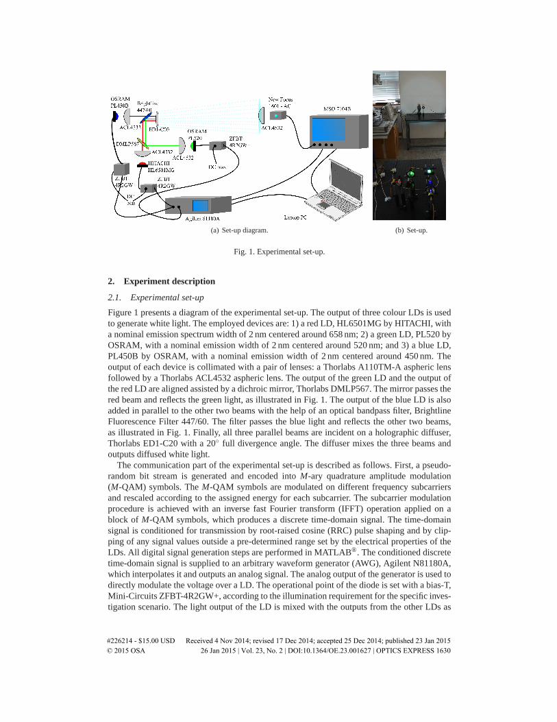
Fig. 1. Experimental set-up.
2. Experiment description
2.1. Experimental set-up
Figure 1 presents a diagram of the experimental set-up. The output of three colour LDs is usedto generate white light. The employed devices are: 1) a red LD, HL6501MG by HITACHI, witha nominal emission spectrum width of 2 nm centered around 658 nm; 2) a green LD, PL520 byOSRAM, with a nominal emission width of 2 nm centered around 520 nm; and 3) a blue LD,PL450B by OSRAM, with a nominal emission width of 2 nm centered around 450 nm. Theoutput of each device is collimated with a pair of lenses: a Thorlabs A110TM-A aspheric lensfollowed by a Thorlabs ACL4532 aspheric lens. The output of the green LD and the output ofthe red LD are aligned assisted by a dichroic mirror, Thorlabs DMLP567. The mirror passes thered beam and reflects the green light, as illustrated in Fig. 1. The output of the blue LD is alsoadded in parallel to the other two beams with the help of an optical bandpass filter, BrightlineFluorescence Filter 447/60. The filter passes the blue light and reflects the other two beams,as illustrated in Fig. 1. Finally, all three parallel beams are incident on a holographic diffuser,Thorlabs ED1-C20 with a 20◦ full divergence angle. The diffuser mixes the three beams andoutputs diffused white light.
The communication part of the experimental set-up is described as follows. First, a pseudo-random bit stream is generated and encoded into M-ary quadrature amplitude modulation(M-QAM) symbols. The M-QAM symbols are modulated on different frequency subcarriersand rescaled according to the assigned energy for each subcarrier. The subcarrier modulationprocedure is achieved with an inverse fast Fourier transform (IFFT) operation applied on ablock of M-QAM symbols, which produces a discrete time-domain signal. The time-domainsignal is conditioned for transmission by root-raised cosine (RRC) pulse shaping and by clip-ping of any signal values outside a pre-determined range set by the electrical properties of theLDs. All digital signal generation steps are performed in MATLAB®. The conditioned discretetime-domain signal is supplied to an arbitrary waveform generator (AWG), Agilent N81180A,which interpolates it and outputs an analog signal. The analog output of the generator is used todirectly modulate the voltage over a LD. The operational point of the diode is set with a bias-T,Mini-Circuits ZFBT-4R2GW+, according to the illumination requirement for the specific inves-tigation scenario. The light output of the LD is mixed with the outputs from the other LDs as
#226214 - $15.00 USD Received 4 Nov 2014; revised 17 Dec 2014; accepted 25 Dec 2014; published 23 Jan 2015 © 2015 OSA 26 Jan 2015 | Vol. 23, No. 2 | DOI:10.1364/OE.23.001627 | OPTICS EXPRESS 1630

described previously. At the receiver site, the white-light output of the diffuser is collected withan aspheric lens, Thorlabs ACL4532, and focused on a p-intrinsic-n (PIN) photodetector, NewFocus 1601FS-AC. The electrical output of the photodetector is digitized with a digital oscil-loscope, Agilent MSO7104B. The captured signal is passed on to the computer and processedin MATLAB® using a series of demodulation steps which include: synchronization, channelestimation, fast Fourier transform (FFT), equalization, and M-QAM demodulation.
In a practical implementation of WDM, a separate photodetector would be used to detectthe communication signal at every wavelength. An optical filter is required in front of each de-tector in order to separate the signals at the different wavelengths. Such optical filters with veryhigh efficiency (> 90%) and a very steep wavelength response profile are already commerciallyavailable. In this study, the AWG is capable of modulating only one LD at a time. Therefore,while all three diodes are switched on during the experiments, they are being modulated oneby one. Hence, the use of an optical filter at the receiver is not required. The optical filter is ex-pected to further improve the operation of the receiver as it would reduce shot noise by filteringout undesired light components and would ensure that the linear operation of the photodetectorcannot be compromised by strong ambient light.
2.2. Modulation parameters
Incoherent visible light communication (VLC) can only be realized using IM/DD. As a result,an information signal has to be both real and non-negative. Conventionally, the OFDM signalis both complex and bipolar. Therefore, it has to be modified before it is suitable for VLC.
A real OFDM signal can be generated with the IFFT operation by imposing Hermitian sym-metry on the block of M-QAM symbols [4, 6]. As part of the Hermitian symmetry, the directcurrent (DC) subcarrier and the 180◦ subcarrier should be set to zero. In addition, half of thesubcarriers, corresponding to the negative frequencies, are set to be complex conjugates ofthe other half, corresponding to the positive frequencies. In an OFDM signal, a total of Nfft
subcarriers are equally spaced in the frequency range [−1/2Ts; 1/2Ts], where Ts is the time-domain signal sampling period which corresponds to the Nyquist rate. Certain subcarriers canbe left unmodulated in order to avoid frequency-dependent distortion effects such as interfer-ence stemming from ambient light sources, low-frequency attenuation due to the DC-wandereffect or signal attenuation due to the frequency response of the front-end elements and thecommunication channel. The spectral efficiency of OFDM can be expressed as:
η =
Nfft2 −1
∑k=0
Mk>0
log2 Mk
Nfft +Ncp(1+β )bits/s/Hz, (1)
where Nfft is the FFT size; Mk is the constellation size modulated on the subcarrier with indexk; Ncp is the OFDM cyclic prefix length; and β is the roll-off factor of the employed RRC filter(for the ideal sinc pulse, β = 0). The single-sided bandwidth of the system can be calculatedas:
B =1
2Ts(1+β ) Hz. (2)
The data rate of the system can be calculated as:
D = 2Bη bits/s. (3)
The FFT size used in this study is Nfft=1024. The cyclic prefix length is set to Ncp=5 afterexhaustive experiments have shown that it is sufficient to remove any significant intersymbolinterference (ISI) effects between the OFDM frames.
#226214 - $15.00 USD Received 4 Nov 2014; revised 17 Dec 2014; accepted 25 Dec 2014; published 23 Jan 2015 © 2015 OSA 26 Jan 2015 | Vol. 23, No. 2 | DOI:10.1364/OE.23.001627 | OPTICS EXPRESS 1631
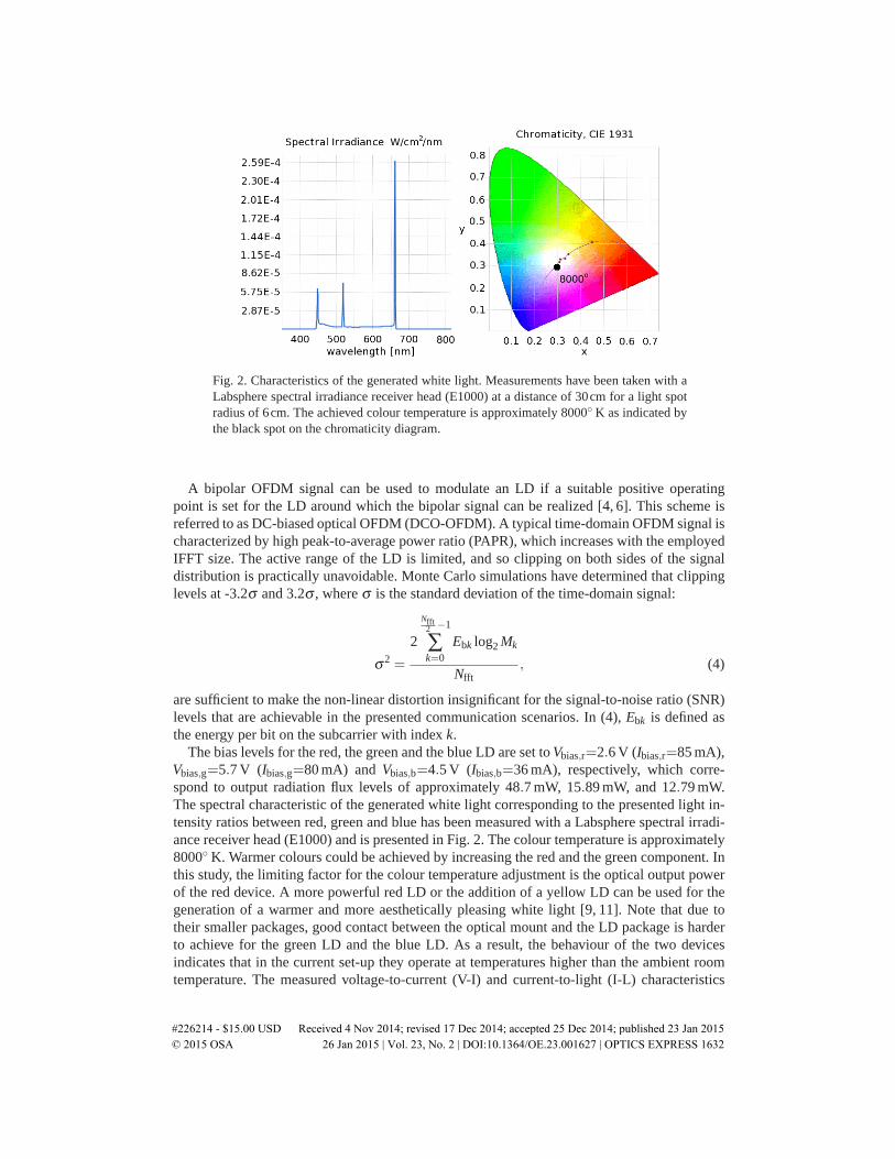
Fig. 2. Characteristics of the generated white light. Measurements have been taken with aLabsphere spectral irradiance receiver head (E1000) at a distance of 30cm for a light spotradius of 6cm. The achieved colour temperature is approximately 8000◦ K as indicated bythe black spot on the chromaticity diagram.
A bipolar OFDM signal can be used to modulate an LD if a suitable positive operatingpoint is set for the LD around which the bipolar signal can be realized [4, 6]. This scheme isreferred to as DC-biased optical OFDM (DCO-OFDM). A typical time-domain OFDM signal ischaracterized by high peak-to-average power ratio (PAPR), which increases with the employedIFFT size. The active range of the LD is limited, and so clipping on both sides of the signaldistribution is practically unavoidable. Monte Carlo simulations have determined that clippinglevels at -3.2σ and 3.2σ , where σ is the standard deviation of the time-domain signal:
σ2 =
2
Nfft2 −1
∑k=0
Ebk log2 Mk
Nfft, (4)
are sufficient to make the non-linear distortion insignificant for the signal-to-noise ratio (SNR)levels that are achievable in the presented communication scenarios. In (4), Ebk is defined asthe energy per bit on the subcarrier with index k.
The bias levels for the red, the green and the blue LD are set to Vbias,r=2.6 V (Ibias,r=85 mA),Vbias,g=5.7 V (Ibias,g=80 mA) and Vbias,b=4.5 V (Ibias,b=36 mA), respectively, which corre-spond to output radiation flux levels of approximately 48.7 mW, 15.89 mW, and 12.79 mW.The spectral characteristic of the generated white light corresponding to the presented light in-tensity ratios between red, green and blue has been measured with a Labsphere spectral irradi-ance receiver head (E1000) and is presented in Fig. 2. The colour temperature is approximately8000◦ K. Warmer colours could be achieved by increasing the red and the green component. Inthis study, the limiting factor for the colour temperature adjustment is the optical output powerof the red device. A more powerful red LD or the addition of a yellow LD can be used for thegeneration of a warmer and more aesthetically pleasing white light [9, 11]. Note that due totheir smaller packages, good contact between the optical mount and the LD package is harderto achieve for the green LD and the blue LD. As a result, the behaviour of the two devicesindicates that in the current set-up they operate at temperatures higher than the ambient roomtemperature. The measured voltage-to-current (V-I) and current-to-light (I-L) characteristics
#226214 - $15.00 USD Received 4 Nov 2014; revised 17 Dec 2014; accepted 25 Dec 2014; published 23 Jan 2015 © 2015 OSA 26 Jan 2015 | Vol. 23, No. 2 | DOI:10.1364/OE.23.001627 | OPTICS EXPRESS 1632

0 0.2 0.4 0.6 0.8 1
−25
−20
−15
−10
−5
0
f [GHz]
|H(
f)|2
RedGreenBlueBack−to−back−3dB Gain
(a) Complete System.
0 0.2 0.4 0.6 0.8 1
−25
−20
−15
−10
−5
0
f [GHz]
|H(
f)|2
Red LDGreen LDBlue LD−3dB Gain
(b) Optical front-end.
Fig. 3. Frequency response of the proposed system.
of the two devices appear to be consistent with operation at temperatures between 40◦ C and60◦ C according to the respective device data sheets. The modulation depth is adjusted accord-ing to the respective scenario under investigation. In general, a larger modulation depth leadsto a higher swing in the optical intensity signal, which increases the SNR at the receiver. How-ever, a higher modulation depth also introduces more non-linearity distortion, which reducesthe achievable SNR at the receiver. In each of the presented cases, the modulation depth is ad-justed empirically in order to maximize the achievable data rate. The sampling frequency of theAWG is fixed at Fs=4 Gs/s, which results in a maximum achievable single-sided bandwidth ofB=1GHz after taking into account the Nyquist sampling criterion and the oversampling factorof 2 used in the pulse shaping procedure. The pulse shaping filter used in the signal generationstep is an RRC filter with a roll-off factor of 0.1. Note that 1 GHz is the analog bandwidth ofthe Agilent MSO7104B oscilloscope and the New Focus photodetector. Hence, it is taken asthe absolute modulation bandwidth limit in this investigation.
The frequency response of the three LDs is consistent in all scenarios investigated in thisstudy and is presented in Fig. 3. The frequency response of the overall system (including thegenerator, the LD, the photodetector, and the oscilloscope) is presented in Fig. 3(a). The 3 dB at-tenuation for the red link occurs around 198 MHz; for the green link it occurs around 245 MHz;and for the blue link the 3dB attenuation occurs around 263 MHz. The frequency response ofthe back-to-back link (generator and oscilloscope only) is also presented in Fig. 3(a). It appearsthat the frequency response of the generator amplifier is the limiting factor for the modulationbandwidth. The frequency responses of the front-end elements only (after accounting for theresponse of the back-to-back link) are presented in Fig. 3(b). The red device exhibits a 3 dBbandwidth of 230 MHz; the green device exhibits a 3 dB bandwidth of 780 MHz; and the bluedevice has a 3 dB bandwidth of approximately 1 GHz. Compared with off-the-shelf LEDs [4,7]and μLEDs [6], the laser diodes exhibit modulation bandwidths which are at least an order ofmagnitude higher. For communication purposes, the LDs clearly appear to be superior to LEDs.
In order to achieve better utilization of the non-flat communication channel, an adaptivebit and energy loading algorithm has been employed in the OFDM generation procedure. Thealgorithm is based on the work of Levin [12] and performs bit and energy allocation based onthe achievable SNR for each communication link. The same bit and energy loading algorithmhas been used to achieve the results in [6].
#226214 - $15.00 USD Received 4 Nov 2014; revised 17 Dec 2014; accepted 25 Dec 2014; published 23 Jan 2015 © 2015 OSA 26 Jan 2015 | Vol. 23, No. 2 | DOI:10.1364/OE.23.001627 | OPTICS EXPRESS 1633
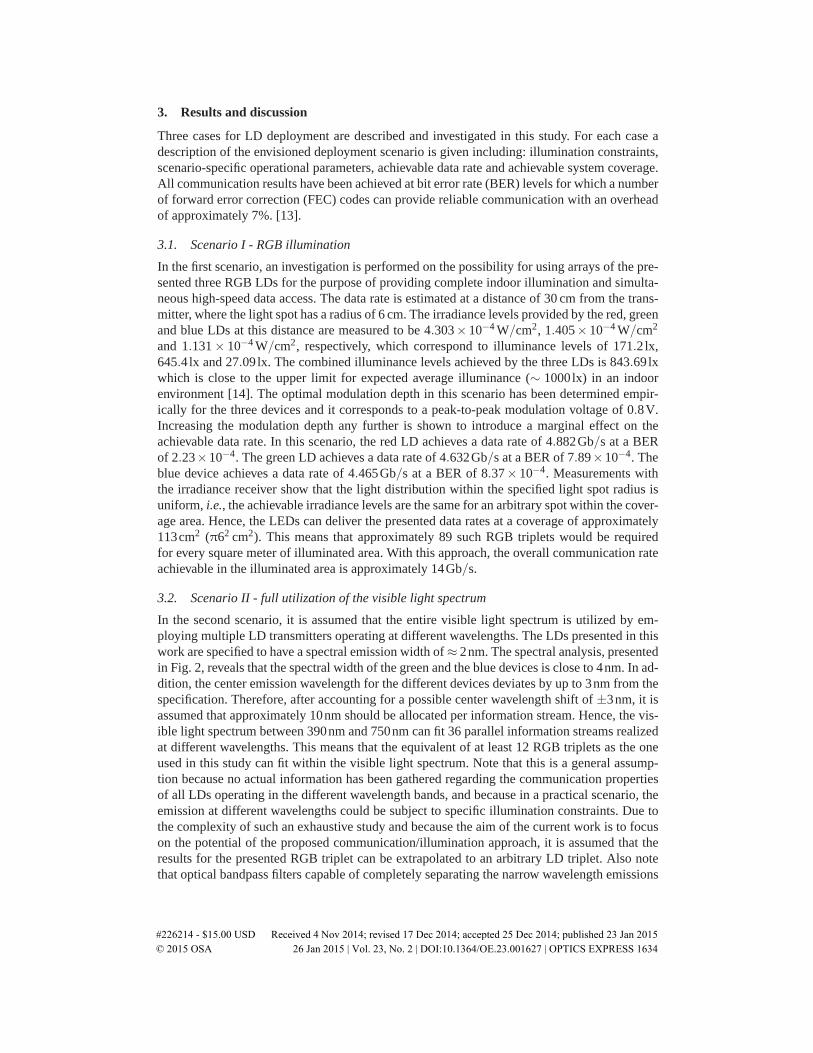
3. Results and discussion
Three cases for LD deployment are described and investigated in this study. For each case adescription of the envisioned deployment scenario is given including: illumination constraints,scenario-specific operational parameters, achievable data rate and achievable system coverage.All communication results have been achieved at bit error rate (BER) levels for which a numberof forward error correction (FEC) codes can provide reliable communication with an overheadof approximately 7%. [13].
3.1. Scenario I - RGB illumination
In the first scenario, an investigation is performed on the possibility for using arrays of the pre-sented three RGB LDs for the purpose of providing complete indoor illumination and simulta-neous high-speed data access. The data rate is estimated at a distance of 30 cm from the trans-mitter, where the light spot has a radius of 6 cm. The irradiance levels provided by the red, greenand blue LDs at this distance are measured to be 4.303× 10⁻⁴ W/cm2, 1.405× 10⁻⁴ W/cm2
and 1.131 × 10⁻⁴ W/cm2, respectively, which correspond to illuminance levels of 171.2lx,645.4lx and 27.09lx. The combined illuminance levels achieved by the three LDs is 843.69lxwhich is close to the upper limit for expected average illuminance (∼ 1000lx) in an indoorenvironment [14]. The optimal modulation depth in this scenario has been determined empir-ically for the three devices and it corresponds to a peak-to-peak modulation voltage of 0.8V.Increasing the modulation depth any further is shown to introduce a marginal effect on theachievable data rate. In this scenario, the red LD achieves a data rate of 4.882Gb/s at a BERof 2.23×10⁻⁴. The green LD achieves a data rate of 4.632Gb/s at a BER of 7.89×10⁻⁴. Theblue device achieves a data rate of 4.465Gb/s at a BER of 8.37× 10⁻⁴. Measurements withthe irradiance receiver show that the light distribution within the specified light spot radius isuniform, i.e., the achievable irradiance levels are the same for an arbitrary spot within the cover-age area. Hence, the LEDs can deliver the presented data rates at a coverage of approximately113cm2 (π62 cm2). This means that approximately 89 such RGB triplets would be requiredfor every square meter of illuminated area. With this approach, the overall communication rateachievable in the illuminated area is approximately 14Gb/s.
3.2. Scenario II - full utilization of the visible light spectrum
In the second scenario, it is assumed that the entire visible light spectrum is utilized by em-ploying multiple LD transmitters operating at different wavelengths. The LDs presented in thiswork are specified to have a spectral emission width of ≈ 2nm. The spectral analysis, presentedin Fig. 2, reveals that the spectral width of the green and the blue devices is close to 4nm. In ad-dition, the center emission wavelength for the different devices deviates by up to 3nm from thespecification. Therefore, after accounting for a possible center wavelength shift of ±3nm, it isassumed that approximately 10nm should be allocated per information stream. Hence, the vis-ible light spectrum between 390nm and 750nm can fit 36 parallel information streams realizedat different wavelengths. This means that the equivalent of at least 12 RGB triplets as the oneused in this study can fit within the visible light spectrum. Note that this is a general assump-tion because no actual information has been gathered regarding the communication propertiesof all LDs operating in the different wavelength bands, and because in a practical scenario, theemission at different wavelengths could be subject to specific illumination constraints. Due tothe complexity of such an exhaustive study and because the aim of the current work is to focuson the potential of the proposed communication/illumination approach, it is assumed that theresults for the presented RGB triplet can be extrapolated to an arbitrary LD triplet. Also notethat optical bandpass filters capable of completely separating the narrow wavelength emissions
#226214 - $15.00 USD Received 4 Nov 2014; revised 17 Dec 2014; accepted 25 Dec 2014; published 23 Jan 2015 © 2015 OSA 26 Jan 2015 | Vol. 23, No. 2 | DOI:10.1364/OE.23.001627 | OPTICS EXPRESS 1634
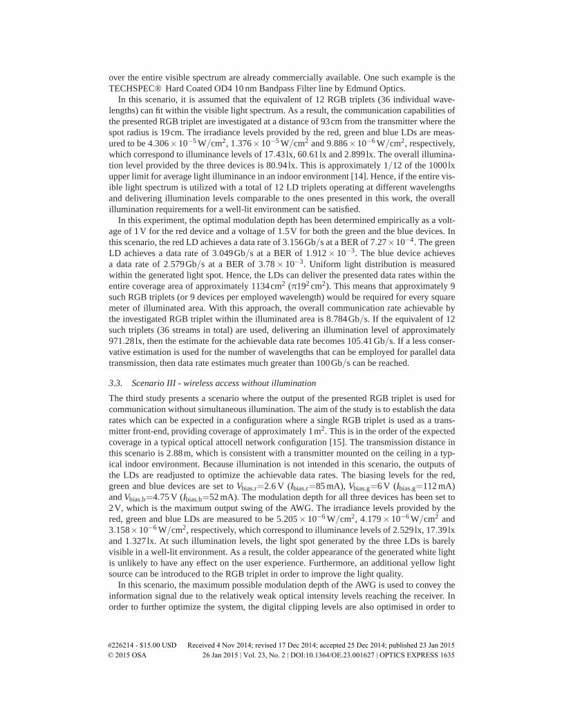
over the entire visible spectrum are already commercially available. One such example is theTECHSPEC® Hard Coated OD4 10 nm Bandpass Filter line by Edmund Optics.
In this scenario, it is assumed that the equivalent of 12 RGB triplets (36 individual wave-lengths) can fit within the visible light spectrum. As a result, the communication capabilities ofthe presented RGB triplet are investigated at a distance of 93cm from the transmitter where thespot radius is 19cm. The irradiance levels provided by the red, green and blue LDs are meas-ured to be 4.306×10⁻⁵ W/cm2, 1.376×10⁻⁵ W/cm2 and 9.886×10⁻⁶ W/cm2, respectively,which correspond to illuminance levels of 17.43lx, 60.61lx and 2.899lx. The overall illumina-tion level provided by the three devices is 80.94lx. This is approximately 1/12 of the 1000lxupper limit for average light illuminance in an indoor environment [14]. Hence, if the entire vis-ible light spectrum is utilized with a total of 12 LD triplets operating at different wavelengthsand delivering illumination levels comparable to the ones presented in this work, the overallillumination requirements for a well-lit environment can be satisfied.
In this experiment, the optimal modulation depth has been determined empirically as a volt-age of 1V for the red device and a voltage of 1.5V for both the green and the blue devices. Inthis scenario, the red LD achieves a data rate of 3.156Gb/s at a BER of 7.27×10⁻⁴. The greenLD achieves a data rate of 3.049Gb/s at a BER of 1.912× 10⁻³. The blue device achievesa data rate of 2.579Gb/s at a BER of 3.78 × 10⁻³. Uniform light distribution is measuredwithin the generated light spot. Hence, the LDs can deliver the presented data rates within theentire coverage area of approximately 1134cm2 (π192 cm2). This means that approximately 9such RGB triplets (or 9 devices per employed wavelength) would be required for every squaremeter of illuminated area. With this approach, the overall communication rate achievable bythe investigated RGB triplet within the illuminated area is 8.784Gb/s. If the equivalent of 12such triplets (36 streams in total) are used, delivering an illumination level of approximately971.28lx, then the estimate for the achievable data rate becomes 105.41Gb/s. If a less conser-vative estimation is used for the number of wavelengths that can be employed for parallel datatransmission, then data rate estimates much greater than 100Gb/s can be reached.
3.3. Scenario III - wireless access without illumination
The third study presents a scenario where the output of the presented RGB triplet is used forcommunication without simultaneous illumination. The aim of the study is to establish the datarates which can be expected in a configuration where a single RGB triplet is used as a trans-mitter front-end, providing coverage of approximately 1m2. This is in the order of the expectedcoverage in a typical optical attocell network configuration [15]. The transmission distance inthis scenario is 2.88m, which is consistent with a transmitter mounted on the ceiling in a typ-ical indoor environment. Because illumination is not intended in this scenario, the outputs ofthe LDs are readjusted to optimize the achievable data rates. The biasing levels for the red,green and blue devices are set to Vbias,r=2.6 V (Ibias,r=85 mA), Vbias,g=6 V (Ibias,g=112 mA)and Vbias,b=4.75 V (Ibias,b=52 mA). The modulation depth for all three devices has been set to2V, which is the maximum output swing of the AWG. The irradiance levels provided by thered, green and blue LDs are measured to be 5.205× 10⁻⁶ W/cm2, 4.179× 10⁻⁶ W/cm2 and3.158×10−6 W/cm2, respectively, which correspond to illuminance levels of 2.529lx, 17.39lxand 1.327lx. At such illumination levels, the light spot generated by the three LDs is barelyvisible in a well-lit environment. As a result, the colder appearance of the generated white lightis unlikely to have any effect on the user experience. Furthermore, an additional yellow lightsource can be introduced to the RGB triplet in order to improve the light quality.
In this scenario, the maximum possible modulation depth of the AWG is used to convey theinformation signal due to the relatively weak optical intensity levels reaching the receiver. Inorder to further optimize the system, the digital clipping levels are also optimised in order to
#226214 - $15.00 USD Received 4 Nov 2014; revised 17 Dec 2014; accepted 25 Dec 2014; published 23 Jan 2015 © 2015 OSA 26 Jan 2015 | Vol. 23, No. 2 | DOI:10.1364/OE.23.001627 | OPTICS EXPRESS 1635
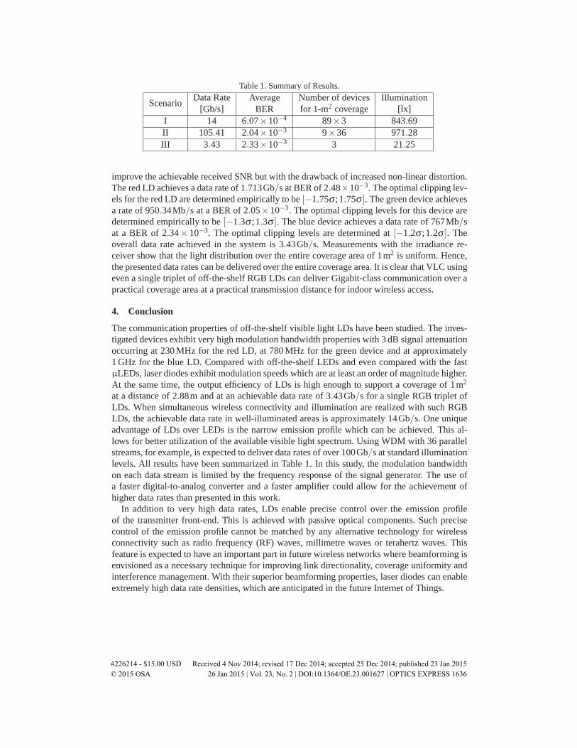
Table 1. Summary of Results.
ScenarioData Rate Average Number of devices Illumination
[Gb/s] BER for 1-m2 coverage [lx]I 14 6.07×10⁻⁴ 89×3 843.69II 105.41 2.04×10⁻³ 9×36 971.28III 3.43 2.33×10⁻³ 3 21.25
improve the achievable received SNR but with the drawback of increased non-linear distortion.The red LD achieves a data rate of 1.713Gb/s at BER of 2.48×10⁻³. The optimal clipping lev-els for the red LD are determined empirically to be [−1.75σ ;1.75σ ]. The green device achievesa rate of 950.34Mb/s at a BER of 2.05×10⁻³. The optimal clipping levels for this device aredetermined empirically to be [−1.3σ ;1.3σ ]. The blue device achieves a data rate of 767Mb/sat a BER of 2.34× 10⁻³. The optimal clipping levels are determined at [−1.2σ ;1.2σ ]. Theoverall data rate achieved in the system is 3.43Gb/s. Measurements with the irradiance re-ceiver show that the light distribution over the entire coverage area of 1m2 is uniform. Hence,the presented data rates can be delivered over the entire coverage area. It is clear that VLC usingeven a single triplet of off-the-shelf RGB LDs can deliver Gigabit-class communication over apractical coverage area at a practical transmission distance for indoor wireless access.
4. Conclusion
The communication properties of off-the-shelf visible light LDs have been studied. The inves-tigated devices exhibit very high modulation bandwidth properties with 3 dB signal attenuationoccurring at 230 MHz for the red LD, at 780 MHz for the green device and at approximately1 GHz for the blue LD. Compared with off-the-shelf LEDs and even compared with the fastμLEDs, laser diodes exhibit modulation speeds which are at least an order of magnitude higher.At the same time, the output efficiency of LDs is high enough to support a coverage of 1m2
at a distance of 2.88m and at an achievable data rate of 3.43Gb/s for a single RGB triplet ofLDs. When simultaneous wireless connectivity and illumination are realized with such RGBLDs, the achievable data rate in well-illuminated areas is approximately 14Gb/s. One uniqueadvantage of LDs over LEDs is the narrow emission profile which can be achieved. This al-lows for better utilization of the available visible light spectrum. Using WDM with 36 parallelstreams, for example, is expected to deliver data rates of over 100Gb/s at standard illuminationlevels. All results have been summarized in Table 1. In this study, the modulation bandwidthon each data stream is limited by the frequency response of the signal generator. The use ofa faster digital-to-analog converter and a faster amplifier could allow for the achievement ofhigher data rates than presented in this work.
In addition to very high data rates, LDs enable precise control over the emission profileof the transmitter front-end. This is achieved with passive optical components. Such precisecontrol of the emission profile cannot be matched by any alternative technology for wirelessconnectivity such as radio frequency (RF) waves, millimetre waves or terahertz waves. Thisfeature is expected to have an important part in future wireless networks where beamforming isenvisioned as a necessary technique for improving link directionality, coverage uniformity andinterference management. With their superior beamforming properties, laser diodes can enableextremely high data rate densities, which are anticipated in the future Internet of Things.
#226214 - $15.00 USD Received 4 Nov 2014; revised 17 Dec 2014; accepted 25 Dec 2014; published 23 Jan 2015 © 2015 OSA 26 Jan 2015 | Vol. 23, No. 2 | DOI:10.1364/OE.23.001627 | OPTICS EXPRESS 1636

Acknowledgment
Prof. Harald Haas acknowledges support by the UK Engineering and Physical Sciences Re-search Council (EPSRC) under Grant EP/K008757/1.
#226214 - $15.00 USD Received 4 Nov 2014; revised 17 Dec 2014; accepted 25 Dec 2014; published 23 Jan 2015 © 2015 OSA 26 Jan 2015 | Vol. 23, No. 2 | DOI:10.1364/OE.23.001627 | OPTICS EXPRESS 1637