edelbrock/magneti marelli pro-flo · edelbrock/magneti marelli powertrain usa, inc pro-flo®...
TRANSCRIPT

Edelbrock / Magneti MarelliPowertrain USA, INC
Pro-Flo®
Multi-Point ElectronicFuel Injection

Pro-Flo EFI Owner’s Manual 08/12
Brochure #63-0053© Edelbrock, LLC 2012 2
CONTENTS
Fuel Injection Fundamentals
Introductory Notes ................................................................................. 2-3
Spark & Fuel Requirements .................................................................. 4-11
Overview - Electronic Engine Control ................................................... 12-13
The Pro-Flo System .............................................................................. 14-19
Calibration Module Operation
Introduction ........................................................................................... 20-23
Operating the Calibration Module ......................................................... 23-26
Display Summary .................................................................................. 27-38
Primary Screens ................................................................................... 39-42
Saving a Set of Modifiers ...................................................................... 43
Restoring a Set of Modifiers ................................................................. 44
System Set-Up and Tuning ................................................................... 45-50
Troubleshooting .................................................................................... 51-64
Wiring Diagrams ................................................................................... 65-67
FUEL INJECTION FUNDAMENTALS
INTRODUCTORY NOTES
Density / Pressure / Vacuum
The Pro-Flo System uses the Speed-Density (SD) method of control. The fuel-flow, spark-advance, and other functions are determined in most part from the critical values of engine speed and intake manifold air density. The intake manifold air density (or charge density) is calculated from inputs of Manifold Absolute Pressure (MAP), Air Charge Temperature (ACT) and coolant temperature. The density represents the relative load (or torque demand of the engine). Later in the manual there will be a discussion on the details of SD control.
Everyone understands the use of RPM as a means of indicating the engine speed. However, there are terms for manifold air (charge) density. The Calibration Module displays values in Inches Of Mercury (“Hg) Manifold Vacuum (MV), since most people are familiar with this measurement as an indicator of relative load; with high vacuum at idle and light loads and low vacuum at heavy loads and Wide Open Throttle (WOT).

Pro-Flo EFI Owner’s Manual 08/12
Brochure #63-0053© Edelbrock, LLC 2012 3
The Manifold Vacuum (MV) value displayed at the Calibration Module is a calculated value derived from the manifold air density. It is calculated on the basis of a set of “standard” conditions; the MV displayed is what the MV would be at these “standard” conditions; which are:
Barometer = 28.94" Hg and Temperature = 80.6 F°.
Camshaft Profile & Manifold Density/Pressure/Vacuum
As noted above, the manifold air density - related to Manifold Vacuum (MV) - is a critical input to the control system. The fuel metering and spark advance values (and others) are determined from density (MV) measurements.
The BASE original calibration in the System ECU was developed on engines that had a particular density (MV) to air-flow “profile”. This “profile” is the relationship between intake air density (MV) and actual air-flow into the engine. In any particular engine at a given RPM, the density (MV) to air-flow relationship is straight forward; an increase in density (MV lower) is an increase in flow. However, this same relationship does not hold true if we compare /across engines with different hardware. For example: Comparing Engine A (Performer Cam) to Engine B (Performer RPM Cam) - both running at 3000 rpm and 10" MV. The actual air-flow will be lower for Engine A vs. Engine B with otherwise identical hardware.
The Most Important Variable Is The Camshaft
The importance of this cannot be over-stated. If everything else stays the same and only the camshaft is changed, a Speed-Density system will need to be re-calibrated in order to account for the altered density (MV) to flow profile. It is important to always maintain a close match between the base calibration and cam used. Other changes, such as valve & port sizes, compression ratio, and even cubic inches; will have only a modest effect on the density (MV) to flow relationship; or, an effect that may be easily taken into account with simple shifts by using your Calibration Module.
INTRODUCTORY NOTES
The camshaft effect upon the base calibration occurs because it alters the density (MV) to flow relationship. Two factors are primarily responsible for this effect:
Pump-Back
The intake valve closes After Bottom Dead Center (ABDC). At higher engine speeds this allows incoming air-fuel mixture to continue filling the cylinder due to the inertia of the air and fuel at high inlet velocities. However, at lower RPM, this late closing can allow some of the mixture to be pumped back into the intake manifold; especially if the throttle opening is small and the reduced inlet density (high MV) increases the pressure difference between the cylinder and manifold. As the intake valve duration is increased, this pump-back phenomenon also increases. And, it has an effect that is “contrary” in nature; as duration increases, the intake air density goes up (MV down) with generally a reduction in actual flow through the engine at low speeds & part-throttle.
Valve Overlap
The intake valve begins to open Before Top Dead Center (BTDC) on the exhaust cycle and the exhaust valve remains open After Top Dead Center into the intake cycle. Therefore, both valves are open at the same time as the engine makes the transition from the exhaust to intake events. This is referred to as valve “overlap”. On small duration camshafts, there is little, if any, overlap. However, if the camshaft profile is altered to improve volumetric efficiencies at higher rpm by using longer valve durations - the result may be a significant amount of overlap. At low RPM, and especially with a small throttle opening, this overlap will result in substantial reverse flow or “cross-talk” between the intake and exhaust side of the engine. Primarily, this amounts to exhaust back-flow into the intake; resulting in elevated intake manifold pressure which translates to increased inlet density (lower MV) simultaneous with dilution of the inlet charge by exhaust gases. This change to a cam with more duration and overlap results in a lower MV but an actual reduction in air flow at lower rpm.
These effects arising from cam changes can have very large effects upon the fuel-metering and spark-advance calibration. Therefore, it is vitally important to start with a base calibration that was developed around a camshaft close to what is in your engine.

Pro-Flo EFI Owner’s Manual 08/12
Brochure #63-0053© Edelbrock, LLC 2012 4
If you have any questions, do not hesitate to call our EFI Technical Hotline at (800) 416-8628, 7am-5pm PST,
Monday-FridayE-mail: [email protected]
SPARK & FUEL REQUIREMENTS
Spark Advance
The charge of air & fuel is burned by a flame-front initiated at the spark-plug. The flame starts as a kernel with a fairly slow rate of expansion; but once a few percent of the charge has been ignited, the combustion process proceeds at high rates. Due to slow initial reaction rates, ignition must occur Before Top Dead Center (BTDC) if maximum efficiency is to be achieved. This is the ADVANCE in ignition - measured in degrees of crank rotation. The optimum advance usually produces the best torque when maximum cylinder pressure is achieved at about 15° After Top Dead Center (ATDC). Depending upon design and operating variables, the spark advance can be from 10° up to more than 50 degrees.
Engine development strives to calibrate spark advance to values named Minimum Best Torque - or MBT. This is the spark advance that will just achieve the maximum torque at some given operating condition of speed and load (as indicated by inlet charge density or manifold vacuum). In most cases, the spark can be advanced several degrees beyond MBT before torque begins to drop. If knock occurs before MBT advance can be determined; the advance is said to be Knock Limited.
The variables that influence spark requirement include base engine design, the particulars of a given configuration (such as cam and compression ratio), fuel used, and operating mode (RPM/Load/Temp). Advance requirement generally increases with speed up to a point where it “peaks” or in some cases decreases slightly with further increase in RPM. Advance requirement decreases with load; the minimum advance at any given engine speed is at WOT. Shown below is a graph of the spark advance requirement for a engine that is equipped with a Pro-Flo system. Spark curves are shown for various engine loads at part-throttle (indicated by manifold vacuum in Hg”) and at WOT.
Pro-Flo EFI System
ENGINE SPEED (RPM)
SPA
RK
AD
VA
NC
E -
CR
AN
K D
EG
RE
ES
15
20
25
30
35
40
45
50
500 1000 1500 2000 2500 3000 3500 4000 4500 5000 5500 6000
SPARK ADV ANCE: VARIOUS ENGINE LOADS
20"
17"7"
WideOpen
Throttle
Pro-Flo EFI Owner’s Manual 08/12
Brochure #63-0053© Edelbrock, LLC 2012 5
SPARK & FUEL REQUIREMENTS
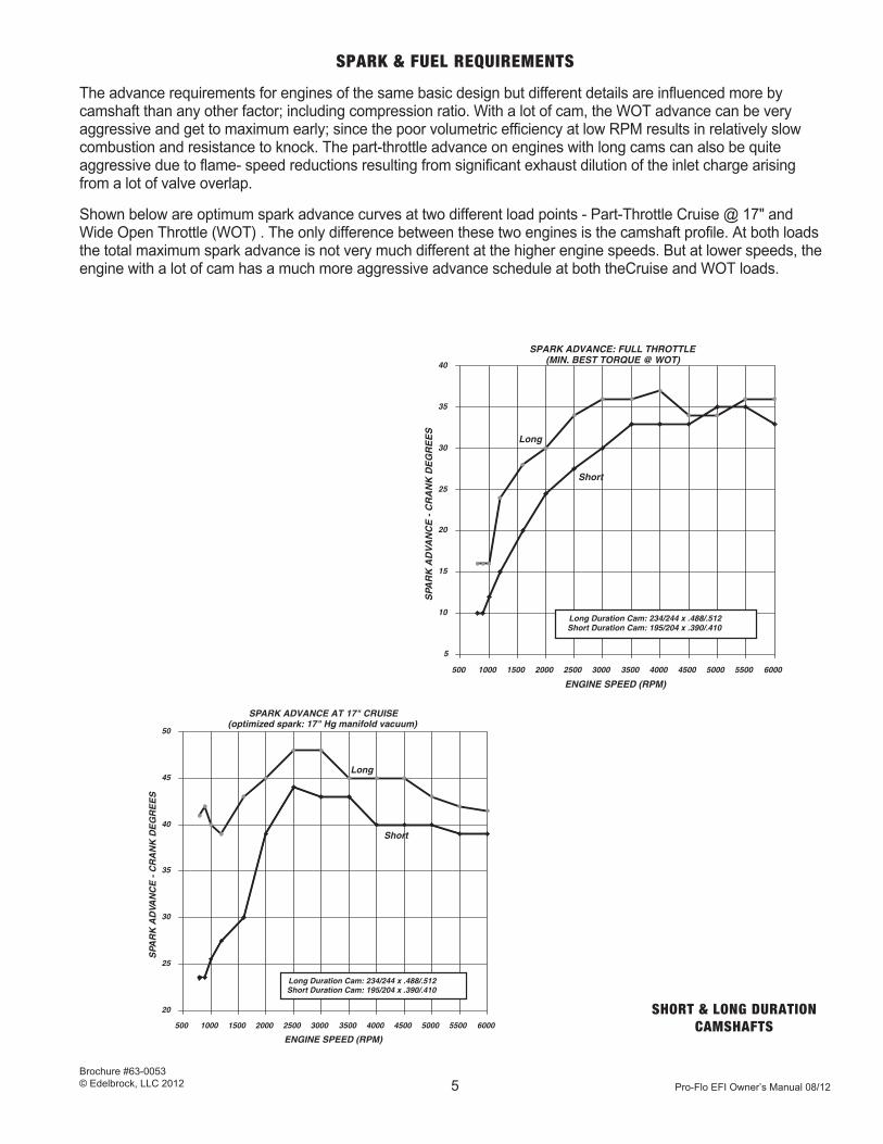
The advance requirements for engines of the same basic design but different details are influenced more by camshaft than any other factor; including compression ratio. With a lot of cam, the WOT advance can be very aggressive and get to maximum early; since the poor volumetric efficiency at low RPM results in relatively slow combustion and resistance to knock. The part-throttle advance on engines with long cams can also be quite aggressive due to flame- speed reductions resulting from significant exhaust dilution of the inlet charge arising from a lot of valve overlap.
Shown below are optimum spark advance curves at two different load points - Part-Throttle Cruise @ 17" and Wide Open Throttle (WOT) . The only difference between these two engines is the camshaft profile. At both loads the total maximum spark advance is not very much different at the higher engine speeds. But at lower speeds, the engine with a lot of cam has a much more aggressive advance schedule at both theCruise and WOT loads.
ENGINE SPEED (RPM)
SPA
RK
AD
VAN
CE
- C
RA
NK
DE
GR
EE
S
20
25
30
35
40
45
50
500 1000 1500 2000 2500 3000 3500 4000 4500 5000 5500 6000
SPARK ADVANCE AT 17" CRUISE(optimized spark: 17" Hg manifold vacuum)
Long Duration Cam: 234/244 x .488/.512Short Duration Cam: 195/204 x .390/.410
Long
Short
ENGINE SPEED (RPM)
SPA
RK
AD
VA
NC
E -
CR
AN
K D
EG
RE
ES
5
10
15
20
25
30
35
40
500 1000 1500 2000 2500 3000 3500 4000 4500 5000 5500 6000
SPARK ADVANCE: FULL THROTTLE(MIN. BEST TORQUE @ WOT)
Long Duration Cam: 234/244 x .488/.512Short Duration Cam: 195/204 x .390/.410
Long
Short
SHORT & LONG DURATION CAMSHAFTS

Pro-Flo EFI Owner’s Manual 08/12
Brochure #63-0053© Edelbrock, LLC 2012 6
SPARK & FUEL REQUIREMENTS
Until the introduction of computer-control of spark, calibration of the spark advance for an engine depended upon the manipulation of distributor components such as the mechanical advance weights, springs, vacuum diaphragm springs, and advance limit stops. This led to many compromises; especially with engines that were owner modified for maximum output. Limitations on part complexity and tolerances allowed for, at most, a dual slope mechanical advance; regardless of the engine spark requirement at WOT. Since avoiding knock was paramount, this often led to mechanical curves for the WOT with less advance than optimum in one or more areas. Also, if the engine used a healthy cam profile, there was no practical way to use a vacuum advance mechanism for achieving required advance at the lowest speeds and loads without over-advancing in many of the higher vacuum mid-range cruise and intermediate loads.
The Pro-Flo system eliminates these handicaps through computer control of the advance, which allows the curves to be tailored for exact engine requirements.
Fuel Metering
The combustion process burns a mixture of air and fuel. This air and fuel mixture may be described in terms of the relative ratio of air to fuel; - the Air/Fuel Ratio (AFR). This value is based on the relative mass - or weight - of air to fuel. For example, if a particular mixture has 15 pounds of air for every 1 pound of fuel; the Air/Fuel Ratio (AFR) is 15. As the relative amount of fuel in the mixture decreases - a leaner mixture - the AFR value becomes larger. An AFR of 16.5 is leaner than AFR of 15.0. As the proportion of fuel becomes greater - a richer mixture - the AFR becomes smaller. AFR of 11.3 is richer than AFR of 13.2.
The AFR of an engine may be measured in several ways, but the most representative and accurate methods use highly specialized exhaust gas analyzers. The AFR data is key to establishing an appropriate fuel metering calibration during engine development.
A fully warmed up engine will run with AFR values as rich as 6.0 to as lean as 22.0 (or even leaner). These are the rich and lean combustion limits, however, and in actual operation the AFR needed at various operating modes will be much closer to the mid-point between these extremes.
AFR Comment AFR Comment
6.0 Rich Burn Limit (fully warm engine) 14.7 Stochiometric AFR
(chemically ideal)
9.0 Black Smoke / Low Power 15.5 Lean Cruise
11.5 Approximate RBT @ WOT 16.5 Usual Best Economy
(Rich Best Torque)
12.2 Safe Best Power @ WOT 18.0 Carbureted Lean Limit
13.3 Approximate LBT @ WOT 22 + EEC/EFI Lean Limit
(Lean Best Torque)
Pro-Flo EFI Owner’s Manual 08/12
Brochure #63-0053© Edelbrock, LLC 2012 7
Engines of substantially different basic design have essentially the same AFR requirements. These metering needs are primarily a function of operating mode; engine temperature, speed (rpm), and relative load. Overall, a high performance engine (fully warmed up) will have AFR values generally in a range from 12.0 to 16.0.
Cold Engine
The combustion process requires vaporized fuel. Much of this vaporization occurs as the air and fuel droplets being drawn past the intake valve, but a substantial portion must take place before the valve opens. In a cold engine; the air, fuel, and all the parts contacted by the fuel are at temperatures that do not promote vaporization. Consequently, additional fuel must be added so that the fraction that does vaporize is sufficient to support combustion. The degree of this fuel addition - or cold enrichment - depends upon the temperature. If the engine is very cold; -20° F for example; the AFR may be as rich as 4.0. As the engine warms up, the AFR must be leaned to normal values.
Idle
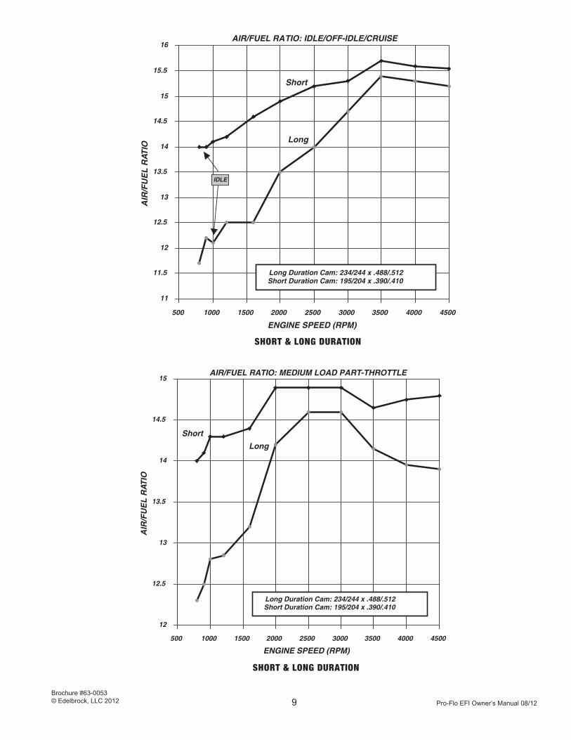
The AFR required for a stable idle is dictated primarily by the camshaft profile. A long duration cam - with big valve overlap - results in an inlet charge that is seriously diluted by exhaust gas (see Introductory Notes). This diluted charge burns slowly and may require a great deal of spark advance. In addition, the combustion tends to be erratic, so a rich mixture is required to minimize cyclic variation (the lopey “rump-rump” characteristic) caused by partial burn cycles. The AFR may need to be 11.5 or richer with a really long duration cam. With a short duration cam, the AFR does not need to be this rich for a stable idle and may be as lean as 14.7 (stoichiometry) in cases where emissions need to be at a minimum.
Off-Idle & Slow Cruise | Low Speed & Light Load
The factors that influence AFR at idle also effect the metering requirements at off-idle operating conditions where the engine rpm is low and the load low (low inlet density - high Manifold Vacuum / or MV). Again, the longer valve duration (and overlap) requires richer AFR for surge-free operation. In the immediate off-idle range the AFR may need to be nearly as rich as the idle; perhaps 12.5 to 13.0 and gradually becoming leaner with increase in speed or load. With a very mild camshaft profile, the engine will often tolerate AFR in the 14.0 to 15.0 range under these same operating conditions.
Cruise & Light Acceleration | Medium Speeds & Loads
As engine rpm increases and the throttle is opened, the effect of valve duration and overlap begin to diminish. There is much less inlet charge dilution and a correspondingly leaner AFR may be used without encountering surge or other driveability problems. AFRs from 14.0 to 15.5 (or even leaner) are common. The “best economy” AFR range from 15.5 to 16.5 requires additional spark advance to compensate for the slow burn rates of lean mixtures.

Pro-Flo EFI Owner’s Manual 08/12
Brochure #63-0053© Edelbrock, LLC 2012 8
SPARK & FUEL REQUIREMENTS
Heavy Load - Part Throttle
As load on the engine increases from additional throttle opening (high inlet density - low MV) the AFR needs to be enrichened to provide more power and avoid the driveability problems associated with lean AFR at high loads. The AFR should be somewhere between the Cruise and WOT AFR values; from about 14.5 to 13.0, depending upon the load and speed.
Wide Open Throttle (WOT)
All 4-cycle gasoline engines have about the same AFR requirements at WOT, where the objective is maximum torque/power. The leanest AFR that provides maximum torque (power) is known as LBT - Lean Best Torque; usually about 13.3 AFR. The richest, known as RBT - Rich Best Torque; around 11.5 AFR. The spread between LBT and RBT can be somewhat closer than this at high engine speeds. The best target AFR for WOT is between 12.0 and 12.5; which insures best WOT power under all circumstances.
Shown below is a typical AFR “map” for an engine that shows the AFR curves at various operating conditions. Following are AFR curves for two different engine configurations under several sets of operating conditions. The engines differ only in the camshaft specifications. Note that the engine with a long-duration cam has significantly richer AFR in the low speed and load ranges.
ENGINE SPEED (RPM)
AIR
/FU
EL
RA
TIO
11
11.5
12
12.5
13
13.5
14
14.5
15
15.5
16
500 1000 1500 2000 2500 3000 3500 4000 4500 5000 5500 6000
AIR/FUEL RATIO METERING: VARIOUS LOADS
17"
10"
4"
Wide Open Throttle
17"/10"/04"/WOT LOADS
Pro-Flo EFI Owner’s Manual 08/12
Brochure #63-0053© Edelbrock, LLC 2012 9
ENGINE SPEED (RPM)
AIR
/FU
EL
RAT
IO
12
12.5
13
13.5
14
14.5
15
500 1000 1500 2000 2500 3000 3500 4000 4500
AIR/FUEL RATIO: MEDIUM LOAD PART-THROTTLE
Long Duration Cam: 234/244 x .488/.512Short Duration Cam: 195/204 x .390/.410
Long
Short
ENGINE SPEED (RPM)
AIR
/FU
EL
RAT
IO
11
11.5
12
12.5
13
13.5
14
14.5
15
15.5
16
500 1000 1500 2000 2500 3000 3500 4000 4500
IDLE
AIR/FUEL RATIO: IDLE/OFF-IDLE/CRUISE
Long Duration Cam: 234/244 x .488/.512Short Duration Cam: 195/204 x .390/.410
Long
Short
SHORT & LONG DURATION
SHORT & LONG DURATION

Pro-Flo EFI Owner’s Manual 08/12
Brochure #63-0053© Edelbrock, LLC 2012 10
ENGINE SPEED (RPM)
AIR
/FU
EL
RAT
IO
10
11
12
13
14
15
16
17
500 1000 1500 2000 2500 3000 3500 4000 4500
AIR/FUEL RATIO: WIDE OPEN THROTTLE (WOT)
Long Duration Cam: 234/244 x .488/.512Short Duration Cam: 195/204 x .390/.410
Long
Short
ENGINE SPEED (RPM)
AIR
/FU
EL
RAT
IO
10
11
12
13
14
15
16
17
500 1000 1500 2000 2500 3000 3500 4000 4500
AIR/FUEL RATIO: HEAVY LOAD PART-THROTTLE
Long Duration Cam: 234/244 x .488/.512Short Duration Cam: 195/204 x .390/.410
Long
Short
LONG & SHORT DURATION CAMS
LONG & SHORT DURATION CAMS

Pro-Flo EFI Owner’s Manual 08/12
Brochure #63-0053© Edelbrock, LLC 2012 11
SPARK & FUEL REQUIREMENTS
Prior to the development of Electronic Engine Control (EEC) with Electronic Fuel Injection (EFI), fuel metering requirements were met with carburetors and wet-flow manifolds. Carburetors can be fairly sophisticated devices and will perform reasonably well as the basic fuel management controller within certain limitations.
However, there are compromises in carburetor calibration that are not required with electronics. In EFI systems such as ProFlo, the fuel metering is controlled on a mode by mode basis. It is possible, as one example, to calibrate lean cruise modes for best fuel-economy and not suffer undesirable effects with light-load accelerations. This is due to the system capability that allows precise definition of the metering by temperature, speed, and load parameters. You change the fuel at the exact area you desire and nowhere else.
Another Pro-Flo advantage is the multi-point port injection of the fuel. This eliminates nearly all of the “wet flow” problems that are associated with carburetors or throttle-body injection (TBI). Accordingly, fuel distribution to the cylinders is uniform, there is no requirement for manifold heat, cold-engine function is much improved, throttle response is crisp regardless of temperature, and leaner AFRs can be used without driveability problems.
OVERVIEW
ELECTRONIC ENGINE CONTROL
ProFlo is a complete Electronic Engine Control (EEC) system that includes control of fuel injection, spark advance, and idle speed functions. Following is a brief outline of system fundamentals and an explanation of the various basic types of system control.
System Fundamentals
All Electronic Engine Control (EEC) systems use a 4-step process to control the engine:
1) Input From Sensors: Sensors send electrical signals to the Electronic Control Unit (ECU).
2) Status Calculation: The ECU determines the engine “status” by interpreting the sensor inputs. Status includes engine temperature, speed, load, rate of load change, and other items that indicate what is happening to the engine.
3) Output Calculation: Using status data, the ECU calculates the desired output values for spark advance, fuel, and idle control.
4) Output To Actuators: The desired output values are translated into electrical signals that are sent to the ignition module (coil driver), fuel injectors, idle control device, etc. etc.
Status and output calculations are performed by a microprocessor -or microcomputer - in the ECU. The micro runs a program that may be divided into two major parts; the Strategy and the Calibration. Strategy is the logic of the control program. It interprets the inputs and determines what TYPE of output is required. The exact VALUE of the output is determined by Calibration. As one example, the Strategy will determine if an injector must be turned on; and the Calibration determines how much fuel it will flow when it is activated. The ProFlo Calibration Module allows you to alter the output values by modifying selected parts of the Calibration.

Pro-Flo EFI Owner’s Manual 08/12
Brochure #63-0053© Edelbrock, LLC 2012 12
Inputs Calculations Outputs
===== ========= ======
Sensors Actuators
Strategy
* Engine Tuner &
& Calibration
ProFlo Module
Engine
*← ←←←←←←←←←←←←←←←←←←←←←←←←← Performance
ECU
OVERVIEW - ELECTRONIC ENGINE CONTROL
Basic System Types
There are several basic types of EEC/EFI systems. All use engine speed (RPM) as one critical input. They differ in the means used to determine the relative engine loading:
* Alpha-N | Uses RPM and Throttle-Angle as means of control.
* Mass Air Flow | Uses RPM and Inlet Air Flow as means of control.
* Speed-Density | Uses RPM and Inlet Density as means of control.
The Alpha-N type of system is found primarily on race cars. The absolute throttle position (from a Throttle Position Sensor - TPS) and engine speed (RPM) are the values used to define the “status” that then determines the outputs. The advantages of Alpha-N are high air-flow capacity (no air-flow restriction from a mass-air meter) and relative insensitivity to base engine modifications (such as camshaft profile). However, if accuracy at part-throttle is important, Alpha-N suffers from the poor resolution at light loads that is inherent from throttle-angle measurement.
Mass Air Flow (MAF) systems are used on many OEM engines. These systems do not directly measure the mass air-flow, but infer it from another input; such as the electrical current required to keep a heated wire (located in the air-flow) at a known constant temperature. One advantage of MAF is that it is able to “track” air-flow changes in the engine over time as the engine wears and accumulates deposits. Another is that it can adjust to changes in the base engine - such as camshaft profile - provided the changes are fairly modest. The disadvantages are possible flow restrictions and sometimes slow response the air-flow meter (MAF). The slow response requires the system to depend heavily upon “other means” during any rapid changes in load (such as stabbing the throttle to WOT). There may also be problems with finding a flow meter location that does not result in inaccuracies that arise from pulsa-tions in the air stream or reversion.
Speed-Density systems - such as the ProFlo - are also used on many OEM engines. In some cases, the inlet density (derived from the measures of Manifold Absolute Pressure - MAP and the Air Charge Temperature - ACT and coolant temperature) is used to calculate an estimate of air-flow into the engine. In others (such as ProFlo), the density measure is used (along with RPM) to directly describe the operating point and the output values are derived from “look-up tables” in the ECU Calibration. A disadvantage of Speed-Density is sensitivity to the base engine configuration as detailed in the Introductory Notes. Advantages include very fast response to changes in load, a high air-flow potential, and good resolution at light loads. Each type of system has advantages and disadvantages. Your ProFlo system uses Speed-Density (with direct look-up) as the best method for high performance engines used in street-driven vehicles. This system is described in more detail on following pages.
® ® ® ® ® ® ® ® ®
® ®
® ® ® ®

Pro-Flo EFI Owner’s Manual 08/12
Brochure #63-0053© Edelbrock, LLC 2012 13
THE PRO-FLO SYSTEM
Basic System Description
* Application: Refer to Instructions
* Control Method: Speed Density (table look-up)
* Spark Advance: ECU Controlled Ignition Module & Distributor
* Fuel Injection: Sequential Multi-Point
* Throttle-Body: 4-Bore Progressive / 2 Bore
* Idle Air Control: Air By-Pass Solenoid
* User Interface: ProFlo Calibration Module
Speed-Density & Table Look-Up
As previously noted, the ProFlo system uses a Speed-Density means of control. The critical inputs are engine speed (RPM) and inlet air density (as the indicator of relative load). Inlet density is derived from measurements of Manifold Absolute Pressure (MAP) and Air Charge Temperature (ACT). The density is analogous to engine Manifold Vacuum (MV) as an indicator of load. The ProFlo module displays inlet density as a Manifold Vacuum (MV) value.
In the “table look-up” method, the ECU-Calibration contains two-dimensional maps of the engine organized by speed (as RPM) and load (as Density - or MV). These RPM and Density (MV) lines are defined in discrete steps - or “break-points”. The “break-points” cross at intersections referred to as “cells”. Each “cell” is an absolutely unique condition of engine RPM and Density (MV).
1000 2000 3000 4000 5000 7000
WOT
6"
12"
18"
LOAD
RPM
In the example table shown above, the “cells” are empty. If this was a look-up table for spark advance, they would each contain a value in crankshaft degrees. If it was for fuel, the cells would have fuel-flow values as an injector “pulse-width” - which is the time the injector stays open for each shot (usually expressed in milliseconds - ms).

Pro-Flo EFI Owner’s Manual 08/12
Brochure #63-0053© Edelbrock, LLC 2012 14
Your ProFlo system has large look-up tables for spark advance and fuel metering; plus many smaller tables for other control items. The spark table has 128 cells (16 rpm x 8 load). The fuel table has up to 240 cells (16 rpm x 15 load).
Since the engine will only rarely be operating at a point that is exactly within a cell, the look-up values are obtained by doing a linear interpolation (a weighted average) from the exact operating point to the surrounding cell values.
ELECTRONIC CONTROL UNIT (ECU)
System control is performed by the Electronic Control Unit (ECU). Your ProFlo ECU is a 35-pin device that uses a Motorola 68HC11 microprocessor. The unit runs with a clock frequency of 8 MHz, which translates into 2 million computer operations per second. A 32 Kilobyte EPROM contains the Strategy and most of the Calibration. The portion of the Calibration that is accessible to the user through the Calibration Module resides in EEPROM that is part of the 68HC11 micro.
SENSORS
Speed/Phase
A Hall-Effect sensor in the distributor is actuated by eight (8) vanes on a rotating wheel. Each vane represents the TDC (actually 10° BTDC) for the 8 cylinders. This provides the ECU with data it uses to calculate absolute crank position and engine speed. One vane is narrower than the others and therefore has less on time in the Hall-Effect sensor. The ECU recognizes this vane as indicating the cylinder #1 position; which is required data for the use of a sequential fuel-injection routine.
Manifold Absolute Pressure | MAP
This sensor is hooked to the intake manifold with a short section of hose. The length & diameter of the hose should not be changed. The pressure of the air in the intake manifold is one of the two measurements required to determine inlet air density (the other is air temperature) and therefore indicates the ABSOLUTE pressure. Accordingly, the system automatically compensates for barometric pressure variations, including those that occur with an increase in altitude.
Air Charge Temperature | ACT (or Manifold Air Temp - MAT)
This sensor measures the temperature of the inlet air. Together with MAP (above) this data is used to calculate the density of the inlet charge. The sensor is based on a thermistor - a device that changes in electrical resistance with temperature. The ECU sends out a regulated 5 volts and reads the return voltage to calculate the temperature.
Engine Coolant Temperature | ECT
Measures water temperature using a thermistor device (as described above under ACT). Coolant temperature data is used in both spark and fuel control. The required cold enrichment, cold advance, and cold idle speed values are determined from data provided by this sensor.
Throttle Position Sensor | TPS
Integral to the Throttle-Body assembly. A potentiometer. Uses a variable resistance and regulated 5 volt input to provide throttle position data to the ECU. Absolute throttle position and rate of change are used in fuel control (Idle / Part-Throttle / WOT mode recognition), transient fuel enrichment, idle speed control, and other strategies. The TPS is factory adjusted but may need to be tweaked for your application. This is referenced in the SYSTEM START UP section of the instructions and explained in more detail at the SET-UP & CALIBRATION section later in this manual.

Pro-Flo EFI Owner’s Manual 08/12
Brochure #63-0053© Edelbrock, LLC 2012 15
ACTUATORS
Ignition Module
The ECU outputs a control signal to the #3518 ignition amplifier that is used to control both coil saturation time (dwell) and discharge (spark timing). This control signal is sometimes referred to as the EST (Electronic Spark Timing).
Idle Air Control (IAC) Solenoid
The ECU outputs a pulsed signal to the solenoid that controls the amount of air by-passing the throttles. The signal is pulsed at a high frequency. The percentage of “On Time” modulates the valve position for more or less air flow.
Fuel Pump
The ECU controls the fuel pump through a relay. At “key on” the pump will run for several seconds to prime the system and then shuts off. At crank or run the pump is again activated. The pump stops if the engine quits running.
The pump will supply 310 pounds of fuel per hour at nominal system pressure of 3.5 bar (50.75 psi). This assumes a system voltage of only 13.0 volts (14.2 is nominal). This flow is sufficient to maintain a 15% fuel return rate even with the injectors at maximum possible flow rate (static).
Injectors
Injectors are of the high impedance type (12-18 Ohm). Do NOT attempt to use low-resistance injectors in this system, as it will result in damage to the ECU. The “static” condition is when the injector is held open 100% of the time.
Each injector is fired once per intake event (every 720° of engine rotation). The ECU controls the fuel flow deliv-ered to the engine by modulating the “pulse-width” (PW) - or time open - for each of the injection events. The “default” Cal Module display screen you see at power-up has a label FUEL: which displays the injector opening time - or PW - in ms (milliseconds or sec/1000). During warm engine operation this value can be anywhere from 0.0 to 18.0 ms. As load increases (MV decreases), the air-flow increases and more fuel is required; resulting in a larger PW. At a constant load (constant MV), an increase in RPM also results in an increase in air flow and corre-sponding fuel-flow requirement; but in this case the fuel flow increase with RPM is MOSTLY accomplished by the more frequent firing of the injector (doubling the RPM also doubles the number of injections per second). This is not a strict mathematical relationship, but as a general rule the PW varies greatly according to load (MV) but only modestly with speed (at a constant load).
Exhaust Gas Oxygen Sensor | EGO or O2 Sensor
The EGO or O2 sensor is the heated type and sometimes referred to as a HEGO sensor. This sensor provides a voltage signal to the ECU that indicates if the Air Fuel Ratio (AFR) is rich or lean of the “stochiometric” value. Stochiometric AFR for pump gasoline - without any alcohol added - is 14.7. At this AFR, the perfect (theoretical) combustion of air and gasoline will result only in H2O (water vapor) and CO2 (carbon dioxide). There will be no CO (carbon monoxide) or O2 (oxygen) in the exhaust. In fact, there is always some CO (about 0.5%) and O2 (about 0.65%) in the exhaust when engines are run at the “chemically ideal” (or stochiometric) AFR. This sensor uses the exhaust oxygen (O2) concentration to alter the electrical output in a “switch” fashion. If the O2 is less than about 0.6% (AFR richer than 14.7), the output voltage is higher than the switch point. If the concentration is more than about 0.7% (AFR leaner than 14.7), the output is lower than the switch point. The sensor cannot be used to differentiate various degrees of rich or lean AFR; - only whether it is rich or lean of the 14.7 (stochiometric) value.
When the AFR is leaner than stoichiometry (14.7), the Cal Module AFR indicator will be illuminated in red. If richer, the light will be green. If you have decided to operate with the “Closed Loop Fuel” strategy activated (more on this later) and the engine is running at a speed/load point where closed-loop is allowed; the indicator light will alternate between red (lean) and green (rich) as the ECU modulates the AFR close to the stochiometric value of 14.7 AFR.
NOTE: The O2 sensor connector pins “A” and “C” will have the same color wire, the middle “B” wire will be a different color wire.

Pro-Flo EFI Owner’s Manual 08/12
Brochure #63-0053© Edelbrock, LLC 2012 16
STRATEGY & CALIBRATION
As noted previously, this system uses the speed-density method of control with direct table look-up for spark advance, idle control, and injector pulse-width values. The following provides some more detail about system operation:
Spark Advance
The required advance is looked up at the base look-up table for each spark event. The look-up table advance values are MBT at WOT and approximate MBT at Part-Throttle. Idle spark advance is derived from a separate table. On cold-engine start and through warm-up, there is a slight amount of extra advance that comes from yet another table that adds advance on the basis of engine coolant temperature. The spark-advance calibrations were done on the dyno and in vehicles using fuel with a pump octane rating of 93 (R+M/2). The graph “SPARK ADVANCE | VARIOUS ENGINE LOADS” at the “SPARK & FUEL REQUIREMENTS” section is a cross-section of the base spark-advance calibration.
Fuel Injection
The required injector pulse-width (PW) is looked up at the base table for each injection event. The Air-Fuel Ratio (AFR) varies with speed and load. The graph “AFR METERING | VARIOUS LOADS” at the “SPARK & FUEL REQUIREMENTS” section displays a good crosssection view of base fuel metering. The calibration is between LBT and RBT at WOT and Heavy Part-Throttle in order to provide a “safe” best-power performance. Idle and Light/Medium Part-Throttle are calibrated for good driveability without an over-rich AFR. Injection is sequential (instead of batch); meaning that each cylinder has the same timing of injection. The fuel is always injected before the intake valve is opened in order to allow a period of “residence” time that enhances vaporization. As the engine speed increases, the injection timing is advanced. The exact injection timing at each RPM was selected primarily on the basis of the hydrocarbon (HC) emissions profile; with minimum values usually indicating best efficiency and strongly related to surge-free driveability.
In addition to the base fuel metering, the control strategy has provisions to alter the PW for special circumstances. On start and warm-up, cold enrichment is determined by a look-up table that provides a modifier value relative to coolant temperature. During rapid load transients, such as the sudden application of throttle, Transient Enrichment (or Acceleration Enrichment) is provided by a strategy that takes into account the magnitude of the change in load, the engine temperature, and RPM. During any closed-throttle decelerations that begin with the engine speed above about 2300 rpm, the fuel is cut completely off and remains off until the speed drops to about 1800 rpm.
Closed-Loop fuel control is selectable from the Cal Module. The base calibration has this function set to “OFF”. If it is set to “ON” it will operate only when a specified set of conditions are met: 1) HEGO (O2) Sensor activity within limits 2) Coolant temperature above 175 F° 3) Manifold Vacuum less than 16" but more than 4" 4) RPM more than 1850 but less than 4200. When all of these conditions are met, the system will alter the look-up PW value, making it larger (richer) or smaller (leaner) in an effort to achieve the stochiometric AFR (14.7). As previously noted, the HEGO (O2) Sensor cannot “know” any AFR except the stochiometric value where it rapidly switches sensor output from low to high (lean to rich) or high to low (rich to lean). Accordingly, control is achieved by shifting the PW smaller when the sensor indicates rich or larger when it indicates lean. In this fashion, the AFR will rapidly oscillate from slightly rich to slightly lean of stoichiometry (14.7 AFR). When the system has managed to achieve control at 14.7, the AFR indicator light on the face of the Cal Module will alternate between red (lean) and green (rich).
Idle Control
In the base calibration, idle speed is automatically controlled to a selected RPM. The Cal Module allows this feature to be modified or turned off, if so desired. In addition to automatic control of the warm idle speed, the strategy controls the “fast idle” speeds during warm-up and provides a type of “dashpot” function to ease the transition into idle and allow smoother gear changes on manual-transmission vehicles.

Pro-Flo EFI Owner’s Manual 08/12
Brochure #63-0053© Edelbrock, LLC 2012 17
CALIBRATION MODULE OPERATION
Introduction
The Edelbrock/Weber Pro-Flo Calibration Module is your tool for monitoring and adjusting the operation of the Pro-Flo engine management system.
The Calibration Module performs the same functions and serves the same purpose as the lap-top computer required by other electronic fuel injection systems. Operation has been simplified, and the one-piece module fits in the palm of your hand.
The Pro-Flo ECU immediately adjusts the output for each modified engine function. A single key stroke allows you to “save” the new value, which is retained when the system is shut off. The following information describes the general procedure for using the Calibration Module.
DANGER: Under NO circumstances should calibrations be adjusted by the driver of the vehicle while the vehicle is in motion. For your safety and the safety of others, bring the vehicle to a complete stop in a safe location before using the Calibration Module.
THE SCREENS
The DISPLAY screen allows you to view various operating parameters of the system, such as coolant temperature, throttle position, engine RPM, etc. There are four available DISPLAY screens.
Display Screen
RPM: 3000 FUEL: 4.0 msVAC: 12.0° Hg SPK: 36°
Idle: 25% RPM: 3000TPS: 28° Target: 950
RPM: 3000 → •••••••••VAC: 12 → ••••
TH20: 180° F TPS: 28°TAIR: 98° F Volt: 14.5
Some parameters are shown on more than on DISPLAY screen. For example, RPM appears on three of the four DISPLAY screens.
The MODIFIER screen allows you to select a group of calibration items for subsequent modification. There are three categories of modifiers: Fuel Modifiers, Spark Modifiers, and Miscellaneous Modifiers.
<MISC. MODIFIERS>ENTER to select
<SPARK MODIFIERS>ENTER to select
<FUEL MODIFIERS>ENTER to select

Pro-Flo EFI Owner’s Manual 08/12
Brochure #63-0053© Edelbrock, LLC 2012 18
FUEL @ ____ 2000: ±0%EXIT = scroll ENTER
POWER ON
ENTER/EXIT
UPDOWN
UPDOWN
UPDOWN
UP / DOWN
UP / DOWN
ENTER/EXITENTER/EXIT
UP / DOWN
ENTER/EXIT
SAVE RESTORE
EXIT EXIT
UP / DOWN
WEBER/ EDELBROCKPro-Flo EFI System
(1-2 second commercial )
RPM: 3000 FUEL: 4.0 msVAC: 12.0Hg SPK: 36˚
TH20: 180̊ F TPS: 28̊TAIR: 98̊ F Volt: 14.5
Idle: 25% RPM: 3000TPS: 28̊ Target: 950
RPM: 3000 –> •••••••••VAC: 12.0 –> ••••
(software identification)ECU: Q1.3 (c) WEBER ’93fCAL: EDEL xxxx CM: 1.6
< FUEL MODIFIERS > ENTER to select
< SPARK MODIFIERS > ENTER to select
FUEL @ WOT 1000: ±0%EXIT = scroll ENTER
FUEL @ 06" 1000: ± 0%EXIT = scroll ENTER
FUEL @ 12" 1000: ± 0%EXIT = scroll ENTER
FUEL @ 18" 1000: ± 0%EXIT = scroll ENTER
Transient Fuel: ± 0%EXIT = scroll ENTER
Cold Start Fuel: ± 0%EXIT = scroll ENTER
Global Fuel Mod: ± 0%EXIT = scroll ENTER
FUEL @ ____ 1000: ±0%EXIT = scroll ENTER
FUEL @ ____ 3000: ± 0%EXIT = scroll ENTER
FUEL @ ____ 4000: ± 0%EXIT = scroll ENTER
FUEL @ ____ 5000: ± 0%EXIT = scroll ENTER
FUEL @ ____ 7000: ± 0%EXIT = scroll ENTER
SPRK @ WOT 1000: ± 0̊EXIT = (+) = ( - )
SPRK @ 9" 1000: ± 0˚EXIT = (+) = ( - )
SPRK @ 18" 1000: ± 0˚EXIT = (+) =( - )
SPRK @ ____ 1000: ±0̊EXIT = scroll ENTER
SPRK @ ____ 1750: ±0̊EXIT = scroll ENTER
SPRK @ ____ 2500: ±0˚EXIT = scroll ENTER
SPRK @ ____ 3500: ± 0̊EXIT = scroll ENTER
SPRK @ ____ 4500: ± 0̊EXIT = scroll ENTER
SPRK @ ____ 6000: ± 0̊EXIT = scroll ENTER
Global SPRK Mod: ± 0̊EXIT = scroll ENTER
UP DOWN UP DOWN
ENTER
EXIT
UP DOWN
ENTER
EXIT
UP DOWN
Target Idle RPM: 950EXIT = scroll ENTER
Idle Fuel Mod: ± 0%EXIT = (+) = ( - )
UP DOWNIdle Spark Mod: ± 0̊
EXIT = scroll ENTER
Idle Spd Actvty: ± 0%EXIT = (+) = ( - )
Rev limiter RPM: 6750EXIT = scroll ENTER
Base Tim’g set: OFFEXIT = scroll ENTER
Closed loop fuel: OFFEXIT = scroll ENTER
Idle Control: OFFEXIT = scroll ENTER
SAVE data set: A/B/CEXIT = scroll ENTER
RESTORE: baseA/B/CEXIT = scroll ENTER
Saving In progress…
Saved to data set #APress EXIT
Restore In progress…
Data set #A RESTOREDPress EXIT
(Return to main menu)
< MISC. MODIFIERS>ENTER to select
(FROM ANYWHERE IN MENU)
(NOTICE: Some values shown represent arbitrary examples)(DIAGNOSTIC error messages will flash on any screen)
CALIBRA TION MODULE DIAGRAM
EXIT EXIT
PRO-FLO ELECTRONIC FUEL INJECTION
CALIBRATION MODULE DIAGRAM

Pro-Flo EFI Owner’s Manual 08/12
Brochure #63-0053© Edelbrock, LLC 2012 19
The EDIT screen allows you to adjust a particular speed-load point or parameter (such as idle speed) within a particular MODIFIER group.
The SAVE screen and the RESTORE screen are used for the SAVE and RESTORE functions, explained later.
The SOFTWARE I.D. screen allows you to identify which version of Pro-Flo is installed, useful in the event of subsequent updates to the system.
THE KEYS
Six keys, or buttons, are used to move from one screen to another and to edit modifiers. The functions of each of them are as follows:
SAVE
The SAVE key is used to initiate the save function, which can be activated whenever you desire to save the current set of calibration modifiers.
EXIT
The EXIT key is used to perform several operations, depending on what screen is active when the key is pressed.
When an EDIT screen within a MODIFIER group is displayed, pressing the EXIT key will move the flashing cursor to the left until it is at its farthest left position. Pressing the EXIT key again will return from the EDIT screen to the appropriate MODIFIER screen.
When a SAVE or RESTORE screen is displayed, pressing the EXIT key will return the screen to the MODIFIER screen or the DISPLAY screen that was present when the SAVE or RESTORE key was pressed.
When the SOFTWARE I.D. screen is displayed, pressing the EXIT key will return the screen to the DISPLAY screen that was displayed when the ENTER key was pressed.
UP ARROW
The UP ARROW key is used to scroll through the various DISPLAY, MODIFIER, and EDIT screens, increase modifier values when an EDIT screen is displayed, and choose data to save or restore when a SAVE or RESTORE screen is displayed.
DOWN ARROW
The DOWN ARROW key is used to scroll through the various DISPLAY, MODIFIER, and EDIT screens in the opposite direction of the UP ARROW key, decrease modifier values when an EDIT screen is displayed, and choose data to save or restore when a SAVE or
RESTORE screen is displayed.
ENTER
The ENTER key is used to enter an EDIT screen from a MODIFIER screen, move the cursor to the right when an EDIT screen is present, and enter the SOFTWARE I.D. screen from a DISPLAY screen.
RESTORE
The RESTORE key is used to initiate the restore function, which can be activated whenever you desire to restore a set of calibration modifiers or the base calibration, regardless of the screen present when RESTORE is pressed.
FUEL @ WOT 1000 :±0%EXIT ↓ = scroll ENTER
SAVE data set: A/B/CEXIT ↓ = SCROLL ENTER
RESTORE: base A/B/CEXIT ↓ = scroll ENTER
ECU:Q5B (c) WEBER ‘93FCAL: EDEL XXXX CM: 1.6
Pro-Flo EFI Owner’s Manual 08/12
Brochure #63-0053© Edelbrock, LLC 2012 20
OPERATING THE CALIBRATION MODULE
SCROLLING
Scrolling to and from various screens is accomplished by using the UP ARROW, DOWN ARROW, ENTER, and EXIT keys. The four DISPLAY screens, the three MODIFIER screens, and the SOFTWARE I.D. screen, can be viewed this way.
The four DISPLAY screens and the three MODIFIER screens are arranged in a loop. The ARROW keys move the display through this loop in either direction.
POWER-ON
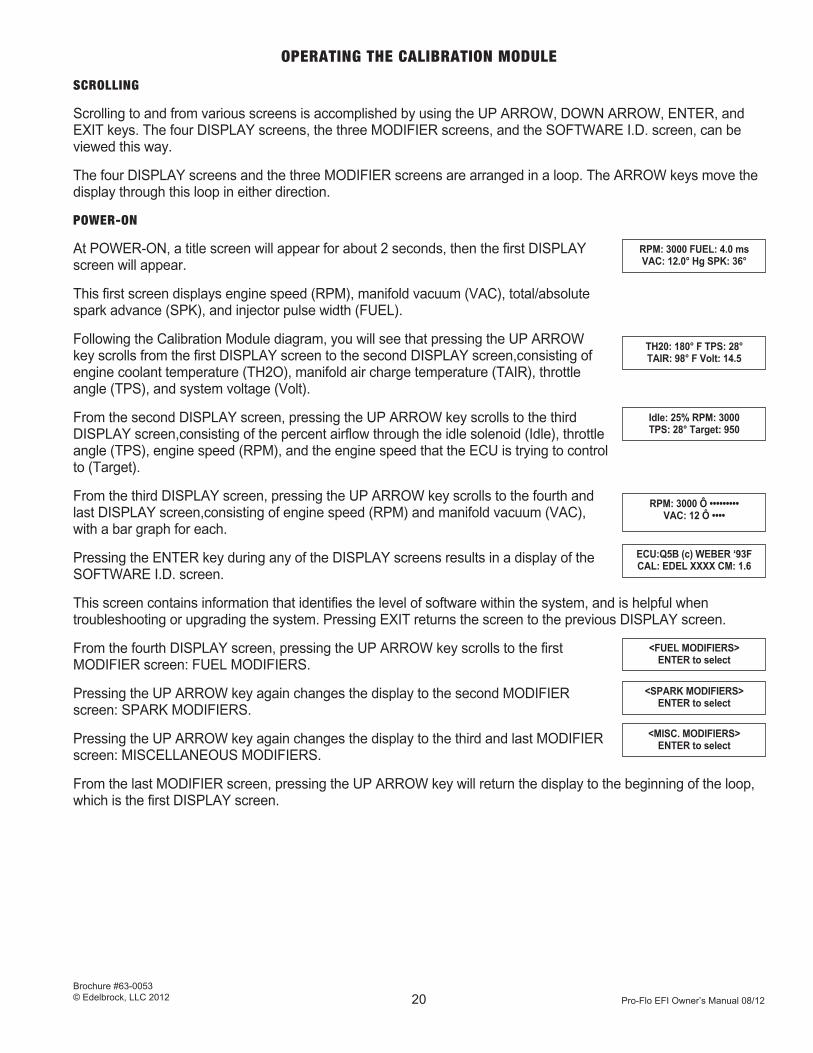
At POWER-ON, a title screen will appear for about 2 seconds, then the first DISPLAY screen will appear.
This first screen displays engine speed (RPM), manifold vacuum (VAC), total/absolute spark advance (SPK), and injector pulse width (FUEL).
Following the Calibration Module diagram, you will see that pressing the UP ARROW key scrolls from the first DISPLAY screen to the second DISPLAY screen,consisting of engine coolant temperature (TH2O), manifold air charge temperature (TAIR), throttle angle (TPS), and system voltage (Volt).
From the second DISPLAY screen, pressing the UP ARROW key scrolls to the third DISPLAY screen,consisting of the percent airflow through the idle solenoid (Idle), throttle angle (TPS), engine speed (RPM), and the engine speed that the ECU is trying to control to (Target).
From the third DISPLAY screen, pressing the UP ARROW key scrolls to the fourth and last DISPLAY screen,consisting of engine speed (RPM) and manifold vacuum (VAC), with a bar graph for each.
Pressing the ENTER key during any of the DISPLAY screens results in a display of the SOFTWARE I.D. screen.
This screen contains information that identifies the level of software within the system, and is helpful when troubleshooting or upgrading the system. Pressing EXIT returns the screen to the previous DISPLAY screen.
From the fourth DISPLAY screen, pressing the UP ARROW key scrolls to the first MODIFIER screen: FUEL MODIFIERS.
Pressing the UP ARROW key again changes the display to the second MODIFIER screen: SPARK MODIFIERS.
Pressing the UP ARROW key again changes the display to the third and last MODIFIER screen: MISCELLANEOUS MODIFIERS.
From the last MODIFIER screen, pressing the UP ARROW key will return the display to the beginning of the loop, which is the first DISPLAY screen.
RPM: 3000 FUEL: 4.0 msVAC: 12.0° Hg SPK: 36°
Idle: 25% RPM: 3000TPS: 28° Target: 950
RPM: 3000 Ô •••••••••VAC: 12 Ô ••••
TH20: 180° F TPS: 28°TAIR: 98° F Volt: 14.5
ECU:Q5B (c) WEBER ‘93FCAL: EDEL XXXX CM: 1.6
<MISC. MODIFIERS>ENTER to select
<SPARK MODIFIERS>ENTER to select
<FUEL MODIFIERS>ENTER to select

Pro-Flo EFI Owner’s Manual 08/12
Brochure #63-0053© Edelbrock, LLC 2012 21
VIEWING AND EDITING MODIFIER VALUES
To edit or view a particular modifier value, you must first use the ARROW keys to scroll to the appropriate MODIFIER screen.
For example, to modify pulse width at a specific load-speed (RPM-VAC) point, you would follow the following procedure (use the Calibration Module diagram or the module itself as you read this procedure):
1. Press the UP ARROW key until the the first MODIFIER screen, FUEL MODIFIERS, is displayed. Below the words FUEL MODIFIERS is the prompt line, indicating which key to press. This particular prompt line reads: “ENTER to select”, indicating that pressing the ENTER key will select the group of modifier values that fall under this heading.
2. Press ENTER to scroll to the screen at the beginning of another loop. The ARROW keys are used to scroll through this loop in the same way that they are used to scroll through the DISPLAY and MODIFIER screens. Note that different prompt lines are used throughout, and are designed to indicate which keys to press to achieve the desired results.
Within the FUEL MODIFIER loop there are four fuel load points (manifold vacuum points), describing the fuel modifier value at WOT, 06 inches, 12 inches, and 18 inches at 1000 rpm, as a percentage of fuel. The first screen that appears when entering the fuel modifier loop describes the fuel modifier value at WOT.
Pressing the EXIT key will return you to the MODIFIER screen. Pressing the ARROW keys will scroll through this loop. Pressing the ENTER key moves the cursor within the screen.
3. Press the ARROW keys to scroll to the fuel load point you wish to modify.
4. To modify the fuel load point selected, press ENTER to scroll to the first fuel modifier matrix screen.
5. Use the ARROW keys to view the six different RPM points available: 1000, 2000, 3000, 4000, 5000, and 7000.
6. Upon reaching the desired RPM point, press ENTER to move the cursor under the modifier value.
7. Press the ARROW keys to increase or decrease the modifier value to obtain the desired results.
8. Press EXIT to move the cursor under the RPM point.
9. Press EXIT again to return to the fuel load point screens. The ARROW keys can be used to scroll to a different fuel load point, or to the other fuel modifiers mentioned above.
10. Press EXIT to return to the FUEL MODIFIERS screen.
The FUEL MODIFIER loop also contains a Transient Fuel modifier, a Cold Start Fuel modifier, and a Global Fuel modifier. These are changed by scrolling to them with the ARROW keys, and pressing ENTER. The cursor will now flash under the modifier value, which can be increased or decreased with the ARROW keys
The procedure for viewing and editing SPARK MODIFIERS, and MISCELLANEOUS MODIFIERS, is the same as for FUEL MODIFIERS.
<FUEL MODIFIERS>ENTER to select
FUEL @ WOT 1000:±0%EXIT ↓ =scroll ENTER
FUEL @ WOT 1000:±0%EXIT ↓ =scroll ENTER
Pro-Flo EFI Owner’s Manual 08/12
Brochure #63-0053© Edelbrock, LLC 2012 22
SAVING A SET OF MODIFIERS
From any screen (except SOFTWARE I.D.), the current set of modifiers, or “data set”, can be stored by pressing the SAVE key. Up to three custom data sets can be saved for future use.
The display asks you to identify which label (A, B, or C) to assign to the data set you intend to save. The ARROW keys are used to move the cursor under the proper label. Press EXIT to return to the main menu. Press ENTER to initiate actual storage of the data set. While this is taking place, a brief message appears on the screen to indicate that saving is in progress. Another message appears confirming which label the data set was saved under. The EXIT key must now be pressed to return to the main menu. Modifiers saved to “A” will be used the next time you start the vehicle.
NOTE: The RED-LEAN/GREEN-RICH indicator light does not function when the save routine is active.
RESTORING A SET OF MODIFIERS
From any screen, the base data set, or any previously saved data set, can be restored. Pressing the RESTORE key initiates the restore routine.
The display asks which data set you want to restore. The ARROW keys are used to move the cursor under the data set label you wish to restore. Press ENTER to initiate actual restore routine.
Press EXIT to return to the main menu.
CAUTION: Only the base data set and any previously saved data sets can be restored. Data that is not saved cannot be restored. Any changes made to the modifier values that are not saved will be lost. If you want to save these changes first, follow the save routine described above.
When the ENTER key is pressed, the ECU will immediately use the restored data set to run the engine. The display will indicate that restore is in progress, and will then confirm which data set has been restored. Press EXIT to return to the main menu.
Note: The RED-LEAN/GREEN-RICH indicator light does not function when the restore routine is active.
ERROR MESSAGES
The ECU continually checks all sensor inputs, and if any value lies outside a predefined window for a given length of time, the Calibration Module will flash an error message indicating which sensor input is faulty. The error message will flash approximately every 5 to 10 seconds until the problem is corrected. If more than one error exists, the error message displayed is for the most critical sensor input. Once that error is corrected the next error will be displayed.
The following is a list of possible error messages, arranged from highest priority to lowest:
MAP Sensor Error
H2O Temp Error
Voltage High/Low
Throttle Input Error
Air Temp Error
O2 Sensor Error
Errors messages, possible causes, and corrections are described in the TROUBLESHOOTING section in this manual.
SAVE data set: A/B/CEXIT ↓=scroll ENTER
RESTORE: base A/B/CEXIT ↓=SCROLL ENTER

Pro-Flo EFI Owner’s Manual 08/12
Brochure #63-0053© Edelbrock, LLC 2012 23
CARE OF THE CALIBRATION MODULE
Do not expose the Calibration Module to rain, snow, or harsh chemicals. Do not leave the module on the dashboard or in direct sunlight. Avoid high temperature storage and operating locations.
Operating temperature range: +5°F to +140°F (-15°C to +60°C)
Storage temperature range: -10°F to +150°F (-23°C to +66°C)
Clean the Calibration Module using only a soft, damp cloth. Use mild dish soap if needed. DO NOT IMMERSE THE CALIBRATION MODULE IN ANY LIQUID; PERMANENT DAMAGE WILL RESULT. Clean the display window with a soft, non-abrasive cloth moistened with water. Apply only light pressure to avoid scratching the window.
CALIBRATION MODULE DISPLAY SUMMARY
DISPLAY 1 (RPM, Fuel, Vac, Sprk)
DISPLAY 2 (Water temp, Throttle position, Air temp, Voltage)
DISPLAY 3 (Idle airflow, RPM, Throttle position, Target idle)
DISPLAY 4 (RPM bar graph, Vac bar graph)
FUEL MODIFIERS ( 27 screens total ) Range of adjustability = +50% / -30% for all points
TRANSIENT FUEL ( +50% / -30%)
COLD START FUEL ( +50% / -30%)
GLOBAL FUEL ( +50% / -30%)
1000 2000 3000 4000 5000 7000
WOT
6"
12"
18"
LOAD
RPM
(24 screens in matrix)
SPARK MODIFIERS (19 screens total) Range of adjustability = +8° / -16° for all points

Pro-Flo EFI Owner’s Manual 08/12
Brochure #63-0053© Edelbrock, LLC 2012 24
1000 1750 2500 3500 4500 6000
WOT
9"
18"
RPM
LOAD
(18 screens in matrix)
MISCELLANEOUS MODIFIERS ( 8 screens total )
Range of Adjustability
TARGET IDLE (500 -1600 RPM)
IDLE FUEL MOD ( ± 50%)
IDLE SPARK MOD ( ± 16° )
IDLE SPEED ACTVTY ( ± 50%)
IDLE CONTROL (ON/OFF)
CLOSED LOOP FUEL (ON/OFF)
BASE TIMING SET (ON/OFF)
REVLIMITER (5000-9500RPM)

Pro-Flo EFI Owner’s Manual 08/12
Brochure #63-0053© Edelbrock, LLC 2012 25
Engine Speed in revolutions per minute.
Injector time-on, in milli-seconds (mS) (1 milli-second = 0.001 second)
RPM: 3000 FUEL: 4.0 mSVAC: 12.0"Hg SPRK: 36º
Manifold vacuum, in inches of mercury. Corrected for temperature and barometric pressure by the ECU
Absolute, or total spark advance, in degrees before piston top dead center in actual crankshaft degrees.
Engine coolant temperature, as read by the ECT sensor, located on the intake manifold water crossover passage.
Throttle angle, as read by the throttle position sensor (TPS) mounted on the side of the throttle body. Should read 10-15° at idle, and 88-90° at full throttle.
Air charge temperature, as read by the air charge temp. sensor (ACT) located in the air cleaner or manifold.
TH2O: 180ºF TPS: 28ºTAIR: 96ºF VOLT: 14.5
DISPLAY SCREEN #2
System voltage. Should always read between 13.8 and 14.8 with engine running for proper system operation.
DESCRIPTION OF CALIBRATION MODULE DISPLAYS
DISPLAY SCREEN #1
Pro-Flo EFI Owner’s Manual 08/12
Brochure #63-0053© Edelbrock, LLC 2012 26
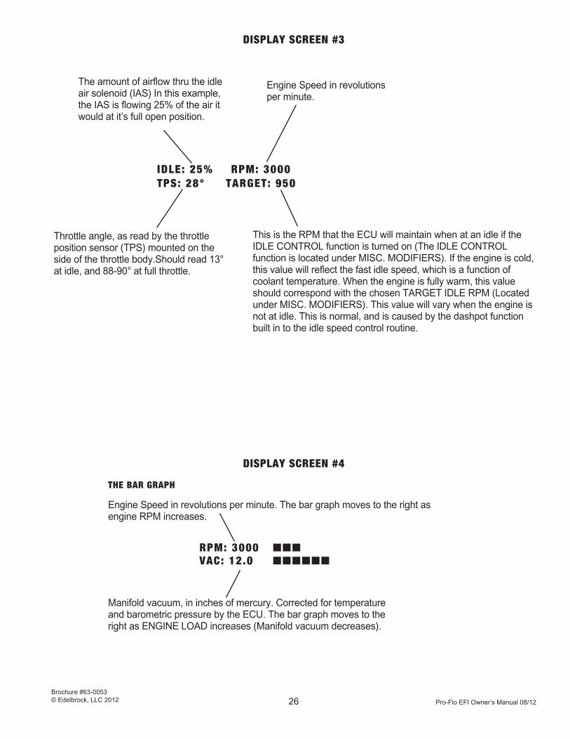
DISPLAY SCREEN #3
The amount of airflow thru the idle air solenoid (IAS) In this example, the IAS is flowing 25% of the air it would at it’s full open position.
Engine Speed in revolutions per minute.
IDLE: 25% RPM: 3000TPS: 28° TARGET: 950
DISPLAY SCREEN #4
THE BAR GRAPH
Engine Speed in revolutions per minute. The bar graph moves to the right as engine RPM increases.
RPM: 3000 ànnnVAC: 12.0 ànnnnnn
Manifold vacuum, in inches of mercury. Corrected for temperature and barometric pressure by the ECU. The bar graph moves to the right as ENGINE LOAD increases (Manifold vacuum decreases).
This is the RPM that the ECU will maintain when at an idle if the IDLE CONTROL function is turned on (The IDLE CONTROL function is located under MISC. MODIFIERS). If the engine is cold, this value will reflect the fast idle speed, which is a function of coolant temperature. When the engine is fully warm, this value should correspond with the chosen TARGET IDLE RPM (Located under MISC. MODIFIERS). This value will vary when the engine is not at idle. This is normal, and is caused by the dashpot function built in to the idle speed control routine.
Throttle angle, as read by the throttle position sensor (TPS) mounted on the side of the throttle body.Should read 13° at idle, and 88-90° at full throttle.

Pro-Flo EFI Owner’s Manual 08/12
Brochure #63-0053© Edelbrock, LLC 2012 27
FUEL MODIFIER SCREEN
FLASHING CURSOR. Indicates parameter to be selected. In this example, the cursor location indicates that the desired RPM point can be selected for modification.
ENGINE RPM POINT.In this example, 1000 RPM has been selected for modification. Other RPM points available are 2000, 3000, 4000, 5000, & 7000.
MODIFIER. The percentage of fuel added or subtracted at that specific LOAD-RPM. When the cursor is flashing to the immediate left of this, the value can be incremented or decremented with the UP/DOWN arrow keys. (LIMITS: ±50%)
ENGINE LOAD POINT. In this example, Wide Open Throttle (WOT), or FULL LOAD, has been selected for modification. When the cursor is flashing to the immediate left of this, one of the four load points (WOT, 06", 12", or 18"), or TRANSIENT, COLD START, or GLOBAL FUEL can be selected with the arrow keys.
FUEL @ WOT n1000: ± 0 % EXIT ↓=scroll ENTER
This indicates that the EXIT key can be pressed, moving the cursor to the left one step at a time, and finally exiting to the primary screen, FUEL MODIFIERS
This indicates that the UP & DOWN arrow keys are used to scroll to a different load point, (or Transient, Cold Start, or Global fuel modifiers), or to select an RPM, depending on where the flashing cursor is located.
NOTE: If the flashing cursor is to the left of the modifier value, then this section will appear as follows:
= (+) ↓=(-)
This indicates that the ENTER key can be pressed, moving the cursor one step at a time to the right.

Pro-Flo EFI Owner’s Manual 08/12
Brochure #63-0053© Edelbrock, LLC 2012 28
TRANSIENT FUEL MODIFIER SCREEN
MODIFIER LABEL
FLASHING CURSOR indicates that this modifier can be incremented or decremented with the UP/DOWN arrow keys.
MODIFIER. Increase or decrease this value to add or subtract the amount of additional fuel injected when a rapid load change occurs (Such as quick change in throttle position).
Transient Fuel: n±0%EXIT =(+) ↓=(-)
This indicates that the EXIT key can be pressed, moving the cursor to the left one step at a time, and finally exiting to the primary screen, FUEL MODIFIERS
This indicates that pressing the UP ARROW key will increment the modifier value.
This indicates that pressing the DOWN ARROW key will decrement the modifier value.
COLD START FUEL MODIFIER
MODIFIER LABEL
FLASHING CURSOR indicates that this modifier can be incremented or decremented with the UP/DOWN arrow keys.
MODIFIER. Increase or decrease this value to add or subtract the amount of additional fuel injected when the engine is below warmed up operating temperatures.
Cold Start Fuel: n± 0%EXIT = (+) ↓= (-)
This indicates that the EXIT key can be pressed, moving the cursor to the left one step at a time, and finally exiting to the primary screen, FUEL MODIFIERS
This indicates that pressing the UP ARROW key will increment the modifier value.
This indicates that pressing the DOWN ARROW key will decrement the modifier value.

Pro-Flo EFI Owner’s Manual 08/12
Brochure #63-0053© Edelbrock, LLC 2012 29
MODIFIER LABEL
FLASHING CURSOR indicates that this modifier can be incremented or decremented with the UP/DOWN arrow keys.
MODIFIER. Increase or decrease this value to add or subtract a percentage of fuel to all LOAD-RPM points to all LOAD-RPM points
GLOBAL FUEL MODIFIER
G l o b a l F u e l : n ± 0 %E X I T = ( + ) ↓= ( - )
This indicates that the EXIT key can be pressed, moving the cursor to the left one step at a time, and finally exiting to the primary screen, FUEL MODIFIERS
This indicates that pressing the UP ARROW key will increment the modifier value.
This indicates that pressing the DOWN ARROW key will decrement the modifier value.
SPARK MODIFIER SCREEN
ENGINE LOAD POINT. In this example, Wide Open Throttle (WOT), or FULL LOAD, has been selected for modification. When the cursor is flashing to the immediate left of this, one of the three load points (WOT, 09", or 18"), or GLOBAL SPARK can be selected using the UP & DOWN arrow keys.
ENGINE RPM POINT. In this example, 1000 RPM has been selected for modification. Other RPM points available are 1750, 2500, 3500, 4500, & 6000.
MODIFIER. The degrees of spark added or subtracted at that specific LOAD-RPM. When the cursor is flashing to the immediate left of this, the value can be incremented or decremented with the UP/DOWN arrow keys. (LIMITS: +8Å/-16Å).
FLASHING CURSOR indicates parameter to be selected. In this example, the cursor location indicates that the desired LOAD point can be selected for modification (Using the arrow keys).
SPRK @ n WOT 1000: ± 0ºEXIT ↓=scrol l ENTER
This indicates that the EXIT key can be pressed, moving the cursor to the left one step at a time, and finally exiting to the primary screen, FUEL MODIFIERS
This indicates that the UP & DOWN arrow keys are used to scroll to a different load point (or Global Spark), or RPM, depending on where the flashing cursor is. NOTE: If the flashing cursor is to the left of the modifier value, then this section will appear as follows:
This indicates that the ENTER key can be pressed, moving the cursor one step at a time to the right.
= (+) ↓=(-)

Pro-Flo EFI Owner’s Manual 08/12
Brochure #63-0053© Edelbrock, LLC 2012 30
GLOBAL SPARK MODIFIER
MODIFIER LABEL
FLASHING CURSOR indicates that this modifier can be incremented or decremented with the UP/DOWN arrow keys.
MODIFIER. Increase or decrease this value to add or subtract spark advance to ALL LOAD-RPM points (Including Idle).
GlobalSpark: n ± 0ºEXIT =(+) ↓ =(-)
This indicates that the EXIT key can be pressed, moving the cursor to the left one step at a time, and finally exiting to the primary screen, SPARK MODIFIERS
This indicates that pressing the UP ARROW key will increment the modifier value.
This indicates that pressing the DOWN ARROW key will decrement the modifier value.
MISCELLANEOUS MODIFIERS
FLASHING CURSOR indicates that this modifier can be incremented or decremented with the UP/DOWN arrow keys.
TARGET (or desired) Idle RPM. When the cursor is flashing to the immediate left of this, the value may be incremented or decremented with the UP & DOWN arrow keys.
TARGETIDLERPM: n 950EXIT = (+) ↓ = (-)
This indicates that the EXIT key can be pressed, moving the cursor to the left one step at a time, and finally exiting to the primary screen, MISC. MODIFIERS
This indicates that pressing the UP ARROW key will increment the modifier value.
This indicates that pressing the DOWN ARROW key will decrement the modifier value.
MODIFIER LABEL

Pro-Flo EFI Owner’s Manual 08/12
Brochure #63-0053© Edelbrock, LLC 2012 31
FLASHING CURSOR indicates that this modifier can be incremented or decremented with the UP/DOWN arrow keys.
MODIFIER. Increase or decrease this value to add or subtract the amount of additional fuel injected when the engine is at an idle.
IDLE FUEL MOD: n ±0%EXIT = (+) ↓ = (-)
This indicates that the EXIT key can be pressed, moving the cursor to the left one step at a time, and finally exiting to the primary screen, MISC. MODIFIERS
This indicates that pressing the UP ARROW key will increment the modifier value.
This indicates that pressing the DOWN ARROW key will decrement the modifier value.
FLASHING CURSOR indicates that this modifier can be incremented or decremented with the UP/DOWN arrow keys.
MODIFIER. The degrees of spark added or subtracted to the base calibration at idle. When the cursor is flashing to the immediate left of this, the value can be incremented or decremented with the UP/DOWN arrow keys. (LIMITS: ±16Å).
IDLE SPARK MOD: n ±0ºEXIT = (+) ↓ = (-)
This indicates that the EXIT key can be pressed, moving the cursor to the left one step at a time, and finally exiting to the primary screen, MISC. MODIFIERS
This indicates that pressing the UP ARROW key will increment the modifier value.
This indicates that pressing the DOWN ARROW key will decrement the modifier value.
MODIFIER LABEL
MODIFIER LABEL

Pro-Flo EFI Owner’s Manual 08/12
Brochure #63-0053© Edelbrock, LLC 2012 32
FLASHING CURSOR indicates that this modifier can be incremented or decremented with the UP/DOWN arrow keys.
MODIFIER. When the cursor is flashing to the immediate left of this, the value can be incremented or decremented with the UP/DOWN arrow keys. (LIMITS: ±50%). See text for more detail.
IDLESPEEDACTIVITY: n ± 0%EXIT = (+) ↓ = (-)
This indicates that the EXIT key can be pressed, moving the cursor to the left one step at a time, and finally exiting to the primary screen, MISC. MODIFIERS
This indicates that pressing the UP ARROW key will increment the modifier value.
This indicates that pressing the DOWN ARROW key will decrement the modifier value.
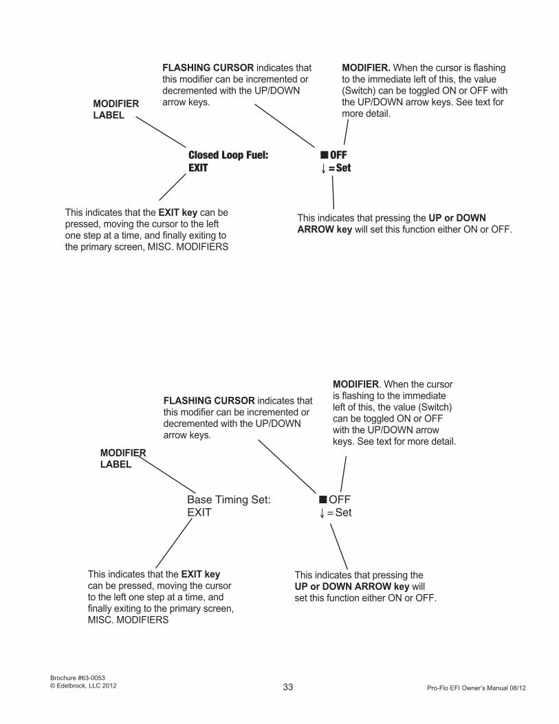
FLASHING CURSOR indicates that this modifier can be incremented or decremented with the UP/DOWN arrow keys.
MODIFIER. When the cursor is flashing to the immediate left of this, the value (Switch) can be toggled ON or OFF with the UP/DOWN arrow keys. See text for more detail.
IDLE CONTROL: nOFFEXIT ↓ = Set
This indicates that the EXIT key can be pressed, moving the cursor to the left one step at a time, and finally exiting to the primary screen, MISC. MODIFIERS
This indicates that pressing the UP or DOWN ARROW key will set this function either ON or OFF.
MODIFIER LABEL
MODIFIER LABEL
Pro-Flo EFI Owner’s Manual 08/12
Brochure #63-0053© Edelbrock, LLC 2012 33
FLASHING CURSOR indicates that this modifier can be incremented or decremented with the UP/DOWN arrow keys.
MODIFIER. When the cursor is flashing to the immediate left of this, the value (Switch) can be toggled ON or OFF with the UP/DOWN arrow keys. See text for more detail.
Closed Loop Fuel: n OFFEXIT ↓ =Set
This indicates that the EXIT key can be pressed, moving the cursor to the left one step at a time, and finally exiting to the primary screen, MISC. MODIFIERS
This indicates that pressing the UP or DOWN ARROW key will set this function either ON or OFF.
FLASHING CURSOR indicates that this modifier can be incremented or decremented with the UP/DOWN arrow keys.
MODIFIER. When the cursor is flashing to the immediate left of this, the value (Switch) can be toggled ON or OFF with the UP/DOWN arrow keys. See text for more detail.
BaseTimingSet: n OFFEXIT ↓ = Set
This indicates that the EXIT key can be pressed, moving the cursor to the left one step at a time, and finally exiting to the primary screen, MISC. MODIFIERS
This indicates that pressing the UP or DOWN ARROW key will set this function either ON or OFF.
MODIFIER LABEL
MODIFIER LABEL

Pro-Flo EFI Owner’s Manual 08/12
Brochure #63-0053© Edelbrock, LLC 2012 34
FLASHING CURSOR indicates that this modifier can be incremented or decremented with the UP/DOWN arrow keys.
MODIFIER. When the cursor is flashing to the immediate left of this, the value can be incremented or decremented with the UP/DOWN arrow keys. RANGE= 5000 to 9500 RPM See text for more details.
Rev Limiter RPM: n6750EXIT =(+) ↓ =(-)
This indicates that the EXIT key can be pressed, moving the cursor to the left one step at a time, and finally exiting to the primary screen, MISC. MODIFIERS
This indicates that pressing the UP ARROW key will increment the modifier value.
This indicates that pressing the DOWN ARROW key will decrement the modifier value.
MODIFIER LABEL

Pro-Flo EFI Owner’s Manual 08/12
Brochure #63-0053© Edelbrock, LLC 2012 35
PRIMARY SCREENS
(DISPLAY & MODIFIER SCREENS)
Using the UP and DOWN arrow keys ( ̄ )SCROLL to the desired display or modifier group:
NOTE: + = PRESS This is the SOFTWARE IDENTIFICATION screen:
RPM: 3000 FUEL: 4.0 mS F ENTER à ECU:Q1.3 (c) WEBER 93F
VAC: 12.0"Hg SPRK: 36º ß F EXIT CAL:EDELXXXX CM:1.6
F
TH20: 180ºF TPS: 28º F ENTER à ECU:Q1.3 (c) WEBER 93F
TAIR: 96ºF VOLT: 14.5 ß F EXIT CAL:EDELXXXX CM:1.6
F
IDLE: 25% RPM: 3000 F ENTER à ECU:Q1.3 (c) WEBER 93F
TPS: 28º TARGET: 950 ß F EXIT CAL:EDELXXXX CM:1.6
F
RPM: 3000 à n n n F ENTER à ECU:Q1.3 (c) WEBER 93F
VAC: 12.0 ß n n n n n n ß F EXIT CAL:EDELXXXX CM:1.6
F
< FUEL MODIFIERS > F ENTER à GO TO FUEL MODIFIER
ENTER to SELECT ß F EXIT PAGE
F
< SPARK MODIFIERS > FENTER à GO TO SPARK MODIFIER
ENTER to SELECT ß F EXIT PAGE
F
< MISC MODIFIERS > F ENTER à GO TO MISC MODIFIER
ENTER to SELECT ß F EXIT PAGE
F
(START AT BEGINNING OF LOOP AGAIN)
z
z
z
z
z
z
z
z
z
z
z
z
z
z

Pro-Flo EFI Owner’s Manual 08/12
Brochure #63-0053© Edelbrock, LLC 2012 36
FUEL MODIFIERS
(EDIT SCREENS)
Using the UP and DOWN arrow keys ( ↓¯) Using the UP and DOWN arrow keys ( ↓¯) Using the UP andDOWN arrow K eys( ↓¯)SCROLL to the desired load point, or other SCROLL to the desired RPM, then press ( ↓¯) add or subtract fuel. Then press fuel modifiers such as TRANSIENT FUEL, ENTER. (This step not applicable to EXIT. Note position of blinking cursor. Then press ENTER. Note position of blinking TRANSIENT, COLD, or GLOBAL FUEL.)cursor. Note position of blinking cursor.
__ BLINKING CURSOR __ BLINKING CURSOR BLINKING CURSOR__
FUEL @ WOT 1000: ± 0 % F ENTER à FUEL @ WOTn1000: ± 0 % F ENTER à FUEL @ WOT 1000: n ± 0 %
EXIT - = scroll ENTER ß F EXIT EXIT - = scroll ENTER ß F EXIT EXIT - = (+) = (-)
F
FUEL @ 06" 1000: ± 0 % F ENTER à FUEL @ 06" n 1000: ± 0 % F ENTER à FUEL @ WOT 1000: n ± 0 %
EXIT - = scrol l ENTER ß F EXIT EXIT - = scroll ENTER ß F EXIT EXIT - = (+) = (-)
F
FUEL @ 12" 1000: ± 0 % F ENTER à FUEL @ 12" n 1000: ± 0 % F ENTER à FUEL @ WOT 1000: n ± 0 %
EXIT - = scrol l ENTER ß F EXIT EXIT - = scroll ENTER ß F EXIT EXIT - = (+) = (-)
F
FUEL @ 18" 1000: ± 0 % F ENTER à FUEL @ 18" n 1000: ± 0 % F ENTER à FUEL @ WOT 1000: n ± 0 %
EXIT - = scrol l ENTER ß F EXIT EXIT - = scroll ENTER ß F EXIT EXIT - = (+) = (-)
F
Transient Fuel: ± 0 % F ENTER à Cold Start Fuel: n ± 0 %
EXIT - = scroll ENTER ß F EXIT EXIT - = (+) = (-)
F
Cold Start Fuel: ± 0 % F ENTER à Cold Start Fuel: n ± 0 %
EXIT - = scroll ENTER ß F EXIT EXIT - = (+) = (-)
F
Global Fuel: ± 0 % F ENTER à Global Fuel: n ± 0 %
EXIT - = scroll ENTER ß F EXIT EXIT - = (+) = (-)
31 2z
z
z
z
z
z
z
z
z
z
z
z
Pro-Flo EFI Owner’s Manual 08/12
Brochure #63-0053© Edelbrock, LLC 2012 37
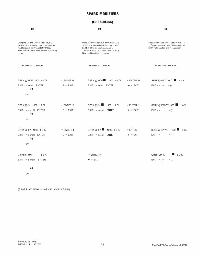
SPARK MODIFIERS
(EDIT SCREENS)
Using the UP and DOWN arrow keys ( ↓¯) Using the UP and DOWN arrow keys ( ↓¯) Using the UP andDOWN arrow K eys( ↓¯)SCROLL to the desired load point, or other SCROLL to the desired RPM, then press ( ↓¯) add or subtract fuel. Then press fuel modifiers such as TRANSIENT FUEL, ENTER. (This step not applicable to EXIT. Note position of blinking cursor.Then press ENTER. Note position of blinking TRANSIENT, COLD, or GLOBAL FUEL.)cursor. Note position of blinking cursor.
__ BLINKING CURSOR __ BLINKING CURSOR BLINKING CURSOR__
SPRK @ WOT 1000: ± 0 % F ENTER à SPRK @ WOTn 1000: ± 0 % F ENTER à SPRK @ WOT 1000: n ± 0 %
EXIT - = scroll ENTER ß F EXIT EXIT - = scroll ENTER ß F EXIT EXIT - = (+) = (-)
F
SPRK @ 9" 1000: ± 0 % F ENTER à SPRK @ 9" n 1000: ± 0 % F ENTER à SPRK @9" WOT 1000: n ± 0 %
EXIT - = scrol l ENTER ß F EXIT EXIT - = scroll ENTER ß F EXIT EXIT - = (+) = (-)
F
SPRK @ 18" 1000: ± 0 % F ENTER à SPRK @ 18" n 1000: ± 0 % F ENTER à SPRK @18" WOT 1000: n ± 0%
EXIT - = scrol l ENTER ß F EXIT EXIT - = scroll ENTER ß F EXIT EXIT - = (+) = (-)
F
Global SPRK: ± 0 % F ENTER à Global SPRK: n ± 0 %
EXIT - = scrol l ENTER ß F EXIT EXIT - = (+) = (-)
F
(START AT BEGINNING OF LOOP AGAIN)
1 2 3z
z
z
z
z
z
z
z
Pro-Flo EFI Owner’s Manual 08/12
Brochure #63-0053© Edelbrock, LLC 2012 38
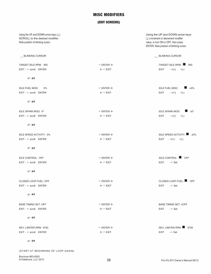
MISC MODIFIERS
(EDIT SCREENS)
UsingtheUPandDOWNarrowkeys( ↓ ) Using the UP and DOWN arrow keys SCROLL to the desired modifier. ( ↓ )incrementordecrementmodifier Notepositionofblinkingcursor. value,orturnONorOFF,thenpress ENTER.Notepositionofblinkingcursor.
__ BLINKING CURSOR ___ BLINKING CURSOR
TARGET IDLE RPM: 950 F ENTER à TARGET IDLE RPM: n 950
EXIT - = scroll ENTER ß F EXIT EXIT - =(+) =(-)
F
IDLE FUEL MOD: 0% F ENTER à IDLE FUEL MOD: n ±0%
EXIT - = scroll ENTER ß F EXIT EXIT - =(+) =(-)
F
IDLE SPARK MOD: 0º F ENTER à IDLE SPARK MOD: n ±0°
EXIT - = scroll ENTER ß F EXIT EXIT - =(+) =(-)
F
IDLE SPEED ACTIVITY: 0% F ENTER à IDLE SPEED ACTIVITY: n ±0%
EXIT - = scroll ENTER ß F EXIT EXIT - =(+) =(-)
F
IDLE CONTROL: OFF F ENTER à IDLE CONTROL: n OFF
EXIT - = scroll ENTER ß F EXIT EXIT - = Set
F
CLOSED LOOP FUEL: OFF F ENTER à CLOSED LOOP FUEL: n OFF
EXIT - = scroll ENTER ß F EXIT EXIT - = Set
F
BASE TIMING SET: OFF F ENTER à BASE TIMING SET: nOFF
EXIT - = scroll ENTER ß F EXIT EXIT - = Set
F
REV. LIMITER RPM: 6750 F ENTER à REV. LIMITER RPM: n 6750
EXIT - = scroll ENTER ß F EXIT EXIT - = Set
F
(START AT BEGINNING OF LOOP AGAIN)
z
z
z
z
z
z
z
z
z
z
z
z
z
z
z
z
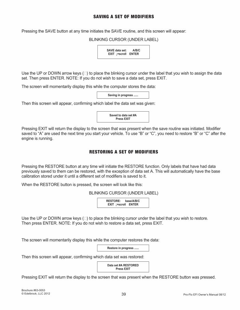
Pro-Flo EFI Owner’s Manual 08/12
Brochure #63-0053© Edelbrock, LLC 2012 39
SAVING A SET OF MODIFIERS
Pressing the SAVE button at any time initiates the SAVE routine, and this screen will appear:
BLINKING CURSOR (UNDER LABEL)
Use the UP or DOWN arrow keys ( ↓) to place the blinking cursor under the label that you wish to assign the data set. Then press ENTER. NOTE: If you do not wish to save a data set, press EXIT.
The screen will momentarily display this while the computer stores the data:
Then this screen will appear, confirming which label the data set was given:
Pressing EXIT will return the display to the screen that was present when the save routine was initiated. Modifier saved to “A” are used the next time you start your vehicle. To use “B” or “C”, you need to restore “B” or “C” after the engine is running.
SAVE data set: A/B/CEXIT ↓=scroll ENTER
Saving in progress ......
Saved to data set #APress EXIT
RESTORING A SET OF MODIFIERS
Pressing the RESTORE button at any time will initiate the RESTORE function. Only labels that have had data previously saved to them can be restored, with the exception of data set A. This will automatically have the base calibration stored under it until a different set of modifiers is saved to it.
When the RESTORE button is pressed, the screen will look like this:
BLINKING CURSOR (UNDER LABEL)
Use the UP or DOWN arrow keys ( ↓) to place the blinking cursor under the label that you wish to restore. Then press ENTER. NOTE: If you do not wish to restore a data set, press EXIT.
The screen will momentarily display this while the computer restores the data:
Then this screen will appear, confirming which data set was restored:
Pressing EXIT will return the display to the screen that was present when the RESTORE button was pressed.
RESTORE: base/A/B/CEXIT ↓=scroll ENTER
Restore in progress ......
Data set #A RESTOREDPress EXIT

Pro-Flo EFI Owner’s Manual 08/12
Brochure #63-0053© Edelbrock, LLC 2012 40
SYSTEM SET UP AND TUNING PROCEDURES
This section describes information and procedures for initial system set up and calibration of the system for your particular vehicle.
Setting the Distributor Timing.
It is mandatory that the distributor be set to 10 degrees before top dead center (TDC). The ECU assumes this 10 degree timing in all spark advance calculations. The spark advance value in the first display screen has this 10 degrees of distributor advance already included.Located in the “MISC. MODIFIERS” submenu is the function “BASE TIMING SET”. “Base timing” refers to mechanical distributor timing only without any electronic spark advance. This function should only be used to set the distributor timing. With base timing ON, run the engine at about 1500 RPM, and using a timing light, set the distributor to 10 degrees before TDC.
WARNING: DO NOT drive vehicle with base timing ON. Serious engine damage may result.
Safeguards are built into the system to make it almost impossible to have the base timing function ON without you knowing it.
Exiting out of this screen is prohibited if base timing is ON.
All SAVES to permanent memory are done with base timing forced OFF.
After the distributor timing is set and the hold-down plate is tightened, turn OFF the base timing function.
Idle Setup
When setting idle, engine must be at full operating temperature (+170°). Set the mechanical portion to best idle condition first, then set electronic idle using the calibration module to achieve proper idle. Follow sections listed below to achieve proper idle.
The idle setup consists of up to five parameters that are located in the “MISC. MODIFIERS” submenu. In addition there are two mechanical adjustments that must be made to the throttle body.
1. Bring vehicle to operating temperature (+170°), then in the “Misc. Modifiers” turn OFF idle control.
2. Set idle stop screw on throttle body to best idle speed. M
3. Set idle fuel modifiers and spark modifiers to best idle quality. C
4. Adjust TPS to 13°.M
5. Recheck Idle speed and quality.M/C
6. Turn ON idle control. C
7. Input same values for target idle using calibration module as where set by the mechanical idle. C
8. With good idle quality and TPS at 13° use calibration module to save to “A”. C
C : Using the Calibration module. M : Mechanical adjustments.

Pro-Flo EFI Owner’s Manual 08/12
Brochure #63-0053© Edelbrock, LLC 2012 41
Spark & Fuel Modifier Set-Points
The various Speed/Load set-points you may access to change spark advance or fuel quantity work in the same fashion as the look-up table “cells” used by the ECU to derive the basic spark and fuel values. When you make a change at a speed/load “Set Point”, all of that change is executed directly at that point. For example, a change of +10% fuel at 12"/2000 will increase the fuel delivery by 10% at that point. As shown below, as the engine operating point moves away from the exact point that was changed (12"/2000 in this example), the effect diminishes in direct proportion to the “distance” to the next “ Set Point”.
Set Point Set Point Set Point Set Point
Speed/Load: 12"/1000 12"/1500 12"/2000 12"/2500 12"/3000
Effect Of +10% 0%↓↓↓ +5%↓↓↓ +10% ↓↓↓ +5% ↓↓↓ 0%
@ 12"/2000.
The example shown demonstrates the effect across a change in RPM. The same effect occurs with respect to load; in this case, the +10% change at 12"/2000 would diminish to 0% at both the 6"/2000 and 18"/2000 Speed/Load (Set) points.
Accordingly, there may be some degree of compromise required when fine-tuning your particular engine. As a general rule however, this will not be the case. Instead, you will often be changing several set points in a “zone” as you strive for the ideal calibration.
Optimizing the Fuel Calibration
Wide-Open-Throttle (WOT)
Unless your engine differs substantially from the standard configurations, the WOT metering will be correct. If you are running small-valve heads, you may want to lean out the WOT from 4000 rpm and up by about 4 to 6 percent (-4% to -6%). If you are not using tubular headers or otherwise have an exhaust system with high back pressure, a similar 4 to 6 percent fuel reduction at 4000 RPM and higher is in order. If you have BOTH small valve heads and a restrictive exhaust, as much as 8 to 12 percent less fuel at 4000 and up may be required. Use the WOT/xxxxRPM fuel modifiers.
The best way to arrive at a feel for where you are is to do timed accelerations across a narrow range of engine speeds, in each case attempting to bracket the Set Point. For example, measure the time from 800 to 1600 rpm in a higher gear. Make several runs and average them. Then add 6% (+6%) to the WOT/1000 set point. Repeat the timed runs. If the times improve, go richer again by 6% and keep going in that direction until the performance does not improve. If more fuel does not help, try 4% leaner from the base calibration. If there is still no improvement, go back to where you were and leave it there. Repeat this for the other Set Points using a 1500 to 2500 rpm pull for the WOT/2000 set point, and so on up the range. Do not be surprised if you cannot find any big improvements. Be especially careful when going lean.
Unless your engine differs substantially from the standard configurations, the WOT metering will be correct. If you are running small-valve heads, you may want to lean out the WOT from 4000 rpm and up by about 4 to 6 percent (-4% to -6%). If you are not using tubular headers or otherwise have an exhaust system with high back pressure, a similar 4 to 6 percent fuel reduction at 4000 RPM and higher is in order. If you have BOTH small valve heads and a restrictive exhaust, as much as 8 to 12 percent less fuel at 4000 and up may be required. Use the WOT/xxxxRPM fuel modifiers.

Pro-Flo EFI Owner’s Manual 08/12
Brochure #63-0053© Edelbrock, LLC 2012 42
The best way to arrive at a feel for where you are is to do timed accelerations across a narrow range of engine speeds, in each case attempting to bracket the Set Point. For example, measure the time from 800 to 1600 rpm in a higher gear. Make several runs and average them. Then add 6% (+6%) to the WOT/1000 set point. Repeat the timed runs. If the times improve, go richer again by 6% and keep going in that direction until the performance does not improve. If more fuel does not help, try 4% leaner from the base calibration. If there is still no improvement, go back to where you were and leave it there. Repeat this for the other Set Points using a 1500 to 2500 rpm pull for the WOT/2000 set point, and so on up the range. Do not be surprised if you cannot find any big improvements. Be especially careful when going lean.
WARNING: If the Cal Module Air/Fuel Ratio (AFR) indicator light should ever stay red (lean) for more than a fraction of a second at WOT; you are very lean for safe engine operation at full load (or you have an exhaust leak that is allowing air to get to the HEGO sensor).
The method suggested above is not practical at lower engine rpm with an automatic transmission; especially if you have a fairly loose converter (which is recommended with a performance cam). An alternative is to measure 0 to 30 mph times while changing the fuel at 1000, 2000, and 3000 rpm. This may not yield any solid evidence one way or another; in which case it can be assumed the baseline (or suggested modifier values) are about right.
Heavy Part-Throttle
Anything less than 8" of manifold vac. (but not WOT) is considered heavy part-throttle. The primary consideration here is good “drive feel” without being too rich. Use the 6"/xxxxRPM set points located under FUEL MODIFIERS to adjust fuel delivery.
Your engine may want something different. The base calibration is on the safe (rich) side. It may be possible to lean out the heavy part-throttle modes without hurting driveability. Watch the AFR light on the Cal Module (red = lean). If the light indicates a consistently lean AFR, especially under 6" vac. above 3000 rpm, exhaust valve durability may suffer. At these fairly heavy loads, a lean AFR is of little benefit to fuel economy so it is best to play it safe.
Light & Medium Load Part-Throttle
These are the cruises and light/medium accelerations. Vac. is 10" or higher. The base calibration has been optimized for good driveability. A modest fuel-economy gain may be obtained from running some areas slightly leaner. Use the 12"/xxxx and 18"/xxxx set points located under FUEL MODIFIERS to adjust fuel delivery at the desired RPM. Driveability and fuel economy will deteriorate if the engine is running too lean. A lean cruise may not yield any fuel economy benefit unless a few degrees of spark advance are added at the same RPM/load points. (Leaner mixtures have slower flame speeds and thus require more advance for maximum efficiency.)
Transient Fuel Enrichment
As noted previously in the description of system operation, the fuel-metering strategy provides additional fuel during heavy load changes. Although this enrichment has been likened to the pump-shot provided by a carburetor, the amount of extra fuel required in a sequential multi-point system is quite small and is needed for only a very short period of time. If you feel the transient performance indicates a lean or rich condition, a TRANSIENT FUEL modifier can alter the activity of this strategy by +\-50%. As a rule however, any perceived misfueling of the engine that is longer in duration than the time it takes to actually move the accelerator pedal is more likely to be associated with the steady state fueling. Too much transient fuel will cause a bigger problem than too little.
Cold Enrichment
Cold engine enrichment can be altered up to +/-50% by the COLD START FUEL modifier. This allows you to richen-up or lean-out the fuel metering in the warm-up period. The base calibration has been tested for appropriate warm-up behavior to temperatures as low as -10°F without problem, but this adjustability will allow you to tweak the calibration to your individual needs. An evaluation of cold engine performance usually requires a few consecutive starts and drives at each level of calibration in order to get a good feel for how it is doing. Unless there are indications of a major problem, make the changes in 10% steps and evaluate each revision over the course of several cold engine start and drive cycles.
Pro-Flo EFI Owner’s Manual 08/12
Brochure #63-0053© Edelbrock, LLC 2012 43
Closed Loop Fuel
Closed-Loop fuel control is selectable from the Cal Module in the MISC MODIFIERS section. The base calibration has this function set to “ON”. If turned “ON” it will operate only when a specified set of conditions are met:
1) HEGO (O2) Sensor activity within limits
2) Coolant temperature above 175° F
3) Manifold Vacuum less than 16" but more than 4"
4) RPM more than 1850 but less than 4200.
When all of these conditions are met, the system will alter the fuel delivery, making it richer or leaner in an effort to achieve the stoichiometric AFR (14.7). As previously noted, the HEGO (O2) Sensor cannot “know” anything about the AFR except that it’s rich, lean or right at the stoichiometric switching point. Accordingly, control is achieved by running the engine leaner when the sensor indicates rich or vise versa. In this fashion, the AFR will rapidly oscillate from slightly rich to slightly lean of stoichiometry (14.7 AFR). When the system is controlling the AFR at 14.7, the indicator light on the Cal Module will alternate between red (lean) and green (rich) with yellow appearing briefly at the switching points.
Operating with Closed Loop Fuel “ON” will provide a roughly stoichiometric (14.7 AFR) mixture for most of the part-throttle operation. There may be some slight variation in drive at the lower speeds and higher vac. modes. At Light/Medium speeds and loads (more than 2500 rpm and 10 to 15" vac.), closed-loop may be slightly richer than the optimum calibration for maximun fuel economy. However, you will never be too far from an optimum part-throttle fuel calibration if running with Closed Loop ON.
Optimizing Spark Calibration
The base calibration was developed using engines that were at the recommended configuration and fuels with pump octane ratings of 93 (R+M/2). Calibration was done on the dyno and in vehicles. The WOT spark is right at MBT everywhere except at the lowest speeds (less than 1000 rpm) where it is Knock Limited. The part-throttle and light throttle advance is generally at MBT. In some light-throttle cruise modes spark timing is retarded to avoid engine surge.
WARNING: BE VERY CAREFUL about adding spark advance. Your engine may respond to small changes here and there. Avoid the temptation to add spark at heavy loads and high rpm unless you have definite indications that more is required (such as a performance improvement at the drag strip). It is very difficult to detect knock at high engine speeds. Serious engine damage can occur before you realize you have gone too far.
The GLOBAL SPARK modifier will change advance at all speeds and loads. IT IS NOT INTENDED TO BE USED AS A SPARK CALIBRATION TOOL. The GLOBAL SPARK MODIFIER is a quick, crude way to reduce spark advance in the event a fuel is used with an octane rating lower than 92 (R+M)/2.
NOTE: Fuel with an octane rating less than 92 is not recommended. Since the base calibration is already advanced to MBT, using the GLOBAL SPARK MODIFIER for additional spark advance is NOT recommended for higher octane fuels (94+).

Pro-Flo EFI Owner’s Manual 08/12
Brochure #63-0053© Edelbrock, LLC 2012 44
Part-Throttle Spark Advance
The operative SPARK MODIFIER used are the 9"/xxxx & 18"/xxxx vacuum/rpm set points. DO NOT use spark knock as an indicator for optimum advance. Individual engine combinations may reaches MBT well before knock at loads with vac. values higher than 6". If you add spark until the onset of knock, you are over-advanced.
At lower RPM and higher vacuum ranges (15" vac. and higher) the base calibration is slightly retarded from MBT and may respond to a little extra advance. If you lean out a cruise mode by a substantial amount, a few degrees more spark in that area may be required in order to achieve best economy.
Rev Limiter
The included rev limiter is adjustable by accessing the REV LIMITER screen located in the MISC. MODIFIERS submenu. This parameter is adjustable in 250 RPM increments from 5000 RPM to 9500 RPM. At the set RPM, fuel delivery and spark advance are adjusted to reduce the engine power output. The fuel will be shut off entirely at 500 RPM above the set point and will not be restored until the RPM falls below the set point.
Save and Restore
The OPERATING INSTRUCTIONS FOR THE CALIBRATION MODULE detail how to SAVE and RESTORE. Following are some pointers on how to use these features to your best advantage.
Up to three (3) unique system calibrations called “data sets” can be saved or restored. These data sets are labeled A, B, and C. In addition, the base calibration (data set) may be restored at any time. Two rules are important to remember:
1) THE SYSTEM WILL ALWAYS INITIALIZE WITH DATA SET “A”.Whenever you turn the ignition key ON, data set “A” is restored automatically. Data sets “B” and “C” can be restored manually. On a new system that has never had any changes, data set “A” is identical to the base calibration.
2) “SAVE” YOUR CHANGES OR THEY WILL BE LOST AT SHUT-DOWN. Changes made with the engine running are put in effect immediately. If the changes are not saved, they will be lost when you turn the key OFF.
Think of the “A” calibration as your “Prime” set-up. As you dial-in the system, save your changes to “B” or “C”. You do not need to wait until you have finished with your entire tuning session. Remember that you manually restore “B” or “C” each time you key ON to run either of those data sets. Once you are confident in your setup save it to “A”.
After you have tuned the system for a while, you may want to experiment with alternate setups but not “lose” your prime calibration (data set A). Again, SAVE the experimental changes to “B” or “C”.
It is easy to move your set ups around. For example: RESTORE from data set “C” and SAVE to data set “A”. Now data sets “A” and “C” are identical and “C” could now be used to save other experimental set ups.

Pro-Flo EFI Owner’s Manual 08/12
Brochure #63-0053© Edelbrock, LLC 2012 45
TROUBLESHOOTING
With proper installation, your Edelbrock/Weber Pro-Flo system will provide a high degree of performance and dependability. Occasionally, component damage, improper installation, or a manufacturing error may cause a failure in system operation. The following are some potential problems that may occur, along with possible causes and corrections. Many of diagnostic procedures require the use of a digital voltmeter.
In the event of any problem upon initial start-up, refer to the system checklist in the SYSTEM START-UP section. In many cases, system failure can be traced to an easily corrected installation error.
Note: Do not use a thrrottle rod, use a throttle cable.
No Communications:
1. No Chip installed. Kit is not shipped with a chip and requires the customer to fill out and mail in for chip.
2. No distributor reference pulses for a long period. (Key on but not started).
SCHEMATIC DRAWING OF EDELBROCK/WEBER
PRO-FLO MAIN SYSTEM HARNESS
Whenever the ignition is ON, the ECU will check the sensor inputs. If any value lies outside a pre-defined window for a given length of time, the Calibration Module will flash an error message indicating which sensor input is faulty. The error message will flash approximately every 5 to 10 seconds until the problem is corrected.If more than one error exists, the error massage displayed is for the most critical sensor input.The following is a list of possible error messages, arranged from highest priority to lowest:
1. MAP Sensor Error
2. Coolant Temp Error
3. Voltage High/Low
4. Throttle Input Error
5. Air Temp Error
6. O2 Sensor Error
7. No communication/ No chip or incorrectly installed
If an error is indicated, it will be necessary to inspect the system for faulty wiring, or bad sensors. For troubleshooting the wiring harness, refer to the wire harness circuit diagram. It is helpful to have a digital voltmeter available in order to check circuit continuity and voltage readings. CAUTION: Care should be taken when probing terminals within a connector; do not force a test probe into terminals. Terminals may be damaged causing poor or no connection.
WARNING: TURN IGNITION OFF whenever connecting or disconnecting ECU from the Main System Harness.
Typically, any problems that occur will exist either in the wiring harness, the connectors, or the sensor itself.

Pro-Flo EFI Owner’s Manual 08/12
Brochure #63-0053© Edelbrock, LLC 2012 46
1. MANIFOLD ABSOLUTE PRESSURE
SENSOR ERROR
THEORY OF OPERATION
The Manifold Absolute Pressure sensor is a three wire device mounted on the air valve and connected to the intake manifold by a short length of vacuum hose. The purpose of this sensor is to send a voltage signal to the ECU that is proportional to the amount of pressure (vacuum) within the intake manifold so the ECU can calculate the correct amount of fuel to deliver to the engine. The Calibration Module will display a MAP SENSOR ERROR message if the signal received by the ECU is not between 0 and 5 volts. Refer to the circuit diagram and note the following circuits.
Sensor Connector ECU pin # Function Cavity
A 11 Sensor ground (internal to ECU)
B 15 MAP signal to ECU
C 30 +5 volt applied to sensor by ECU
TROUBLESHOOTING THE MAP SENSOR AND CIRCUIT
If a MAP sensor error is present, check the value displayed for VAC on the Calibration Module, with the ignition ON but the engine not running. Proceed as follows:
IF VAC DISPLAYED IS 0.0":
POSSIBLE CAUSE CORRECTIVE ACTION
A. CONNECTOR not plugged in. Seat connector fully.
B. CONNECTOR DAMAGE Replace connector. at sensor or ECU.
C. OPEN CIRCUIT Return wire harness to With ignition OFF, disconnect Edelbrock for inspection MAP sensor & ECU from harness and/or replacement Check resistance between MAP connector cavity B and ECU connector cavity 15. Resistance should be not greater than 0.4 ohms.
D. GROUNDED CIRCUIT Return wire harness to With ignition OFF, disconnect Edelbrock for inspection MAP sensor & ECU from harness. and/or replacement. Check resistance between cavity B and ground. There should be infinite resistance (No continuity).

Pro-Flo EFI Owner’s Manual 08/12
Brochure #63-0053© Edelbrock, LLC 2012 47
E. NO VOLTAGE supplied to sensor. Return wire harness to With ECU plugged in, ignition Edelbrock for inspection turned ON, engine not running and/or replacement. disconnect MAP sensor connector and measure voltage across cavities A & C. Voltage should be between 4.9 and 5.1 volts.
F. FAULTY SENSOR Replace sensor. (GM pn 16006835)
IF VAC DISPLAYED IS GREATER THAN 25.0"
POSSIBLE CAUSE CORRECTIVE ACTION
A. SHORT IN HARNESS. With ignition Return wire harness to OFF, disconnect ECU & MAP Edelbrock for inspection sensor from harness. Check and/or replacement. resistance between ground & MAP sensor connector cavities A B & C. Resistance reading should be infinite (No continuity).
B. FAULTY SENSOR Replace sensor (GM pn 16006835)
2. COOLANT TEMP ERROR
THEORY OF OPERATION
The Coolant Temperature Sensor is a two terminal device located on the intake manifold with the sensor tip in contact with engine coolant. The electrical resistance across the two terminals of the sensor is inversely proportional to the temperature of the tip of the sensor. As temperature increases, the resistance across the terminals decreases. The ECU uses this information for, among other things, cold engine enrichment.
The COOLANT TEMP ERROR will flash if the signal received by the ECU from the Coolant Temperature Sensor is not within the proper range of values.
NOTE: If the engine is running and the ECU detects a Coolant Temperature Sensor error, the TH2O (water tem-perature) value displayed by the Calibration Module will default to 95°F. If the engine is not running, but the ignition is turned ON, the TH2O value displayed by the Calibration Module will be abnormally high or low.
TROUBLESHOOTING THE COOLANT TEMPERATURE SENSOR AND CIRCUIT
If a COOLANT TEMP ERROR message is present, look at the TH2O value displayed by the Calibration Module with the ignition ON, but the engine not running, and proceed as follows:
IF TEMPERATURE READING IS ABNORMALLY LOW (example: -67°F):
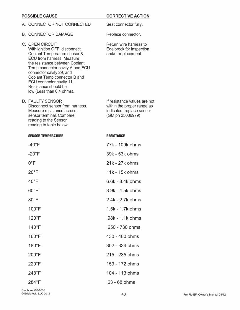
Pro-Flo EFI Owner’s Manual 08/12
Brochure #63-0053© Edelbrock, LLC 2012 48
POSSIBLE CAUSE CORRECTIVE ACTION
A. CONNECTOR NOT CONNECTED Seat connector fully.
B. CONNECTOR DAMAGE Replace connector.
C. OPEN CIRCUIT Return wire harness to With ignition OFF, disconnect Edelbrock for inspection Coolant Temperature sensor & and/or replacement ECU from harness. Measure the resistance between Coolant Temp connector cavity A and ECU connector cavity 29, and Coolant Temp connector B and ECU connector cavity 11. Resistance should be low (Less than 0.4 ohms).
D. FAULTY SENSOR If resistance values are not Disconnect sensor from harness. within the proper range as Measure resistance across indicated, replace sensor sensor terminal. Compare (GM pn 25036979) reading to the Sensor reading to table below:
SENSOR TEMPERATURE RESISTANCE
-40°F 77k - 109k ohms
-20°F 39k - 53k ohms
0°F 21k - 27k ohms
20°F 11k - 15k ohms
40°F 6.6k - 8.4k ohms
60°F 3.9k - 4.5k ohms
80°F 2.4k - 2.7k ohms
100°F 1.5k - 1.7k ohms
120°F .98k - 1.1k ohms
140°F 650 - 730 ohms
160°F 430 - 480 ohms
180°F 302 - 334 ohms
200°F 215 - 235 ohms
220°F 159 - 172 ohms
248°F 104 - 113 ohms
284°F 63 - 68 ohms

Pro-Flo EFI Owner’s Manual 08/12
Brochure #63-0053© Edelbrock, LLC 2012 49
IF TEMPERATURE READING IS ABNORMALLY HIGH
(example: +265°F):
POSSIBLE CAUSE CORRECTIVE ACTION
A. ENGINE OVERHEATED Fix cooling system problem. (Over 265°F).
B. SHORT TO GROUND Return wire harness to With ignition OFF, disconnect Edelbrock for inspection Coolant Temp Sensor & ECU from and/or replacement. harness. Measure the resistance between sensor connector cavity A and ground. Reading should be infinite (No continuity).
C. FAULTY SENSOR If resistance values are not Disconnect sensor from harness. within the proper range as Measure resistance across indicated, replace sensor. sensor terminal. Compare reading (GM pn 25036979) to the SensorTemperature/ Resistance table above.
3. VOLTAGE HIGH/LOW
This error will be present if the voltage supplied to the ECU is greater than 15.2 volts or less than 11.2 volts.
If a VOLTAGE HIGH/LOW error message is present, look at the VOLT reading on the Calibration Module display and proceed as follows:
IF VOLTAGE DISPLAYED IS GREATER THAN 15.2 VOLTS:
POSSIBLE CAUSE CORRECTIVE ACTION
A ALTERNATOR OVERCHARGING Service alternator/regulator.
VOLTAGE LESS THAN 11.2 VOLTS:
POSSIBLE CAUSE CORRECTIVE ACTION
A. ALTERNATOR UNDERCHARGING Service alternator/regulator.
B. POOR CONNECTIONS Clean battery terminals; on vehicle charging system check cable connections & engine grounds.

Pro-Flo EFI Owner’s Manual 08/12
Brochure #63-0053© Edelbrock, LLC 2012 50
4. THROTTLE INPUT ERROR
If a THROTTLE INPUT ERROR is present, inspect the Throttle Position Sensor. Make sure all sensor attaching screws are tight. Next, check the value displayed for TPS on the Calibration Module, with the ignition ON but the engine not running. Proceed as follows:
IF TPS VALUE IS 90.0°:
POSSIBLE CAUSE CORRECTIVE ACTION
A CONNECTOR NOT PLUGGED IN Seat connector fully. Check Bad Power conection to pro-Flo for battery voltage at lug ring
B. CONNECTOR DAMAGE AT SENSOR Replace connector. OR ECU
C. OPEN CIRCUIT Return wire harness to With ignition OFF, disconnect Edelbrock for inspection the Throttle Position Sensor and/or replacement. and ECU from harness. Measure resistance between sensor connector cavity C and ECU connector cavity 17. Resistance should be no greater than 0.4 ohms.
D. NO VOLTAGE supplied to Return wire harness to sensor. Disconnect sensor. Edelbrock for inspection With ECU plugged in and and/or replacement. ignition turned ON, and engine not running, measure voltage across cavities A & B. Voltage should be between 4.9 and 5.1 volts.
E. FAULTY SENSOR Replace sensor.
IF TPS VALUE IS 0.0°:
POSSIBLE CAUSE CORRECTIVE ACTION
A. GROUNDED CIRCUIT Return wire harness to With ignition OFF, disconnect Edelbrock for inspection sensor and ECU from harness. and/or replacement. Check resistance between cavity C and ground. Resistance should be infinite (No continuity).
B FAULTY SENSOR Replace sensor.
C. Improper Adjustment Adjust to 13°

Pro-Flo EFI Owner’s Manual 08/12
Brochure #63-0053© Edelbrock, LLC 2012 51
5. AIR TEMP ERROR
THEORY OF OPERATION
The Manifold Air Temperature sensor is a two terminal device located in the intake manifold or air cleaner with the sensor tip in contact with engine inlet air. The electrical resistance across the two
terminals of the sensor is inversely proportional to the temperature of the tip of the sensor. As the temperature of the sensor tip increases, the resistance across the terminals decreases. The ECU uses this information, along with Manifold Absolute Pressure information, to calculate inlet air density so that the proper amount of fuel can be delivered.
The AIR TEMP ERROR screen will flash if the signal received by the ECU from the Manifold Air Temperature sensor is not within the proper range of values.
NOTE: Unlike the Coolant Temperature Sensor error, the
Calibration Module will not display a default value of 95°F for TAIR when a failure has been detected while the engine is running.
TROUBLESHOOTING THE MANIFOLD
AIR TEMPERATURE CIRCUIT
If an AIR TEMP ERROR message is present, look at the TAIR value displayed by the Calibration Module and proceed as follows:
IF TEMPERATURE IS ABNORMALLY LOW (example: -103°F)
POSSIBLE CAUSE CORRECTIVE ACTION
A. CONNECTOR NOT CONNECTED Seat connector fully.
B CONNECTOR DAMAGE Replace connector. at sensor or ECU
C. OPEN CIRCUIT Return wire harness to With ignition OFF, disconnect Edelbrock for inspection the Manifold Air Temp sensor and/or replacement. and ECU from harness. Measure resistance between sensor connector cavity A and ground. Reading should be infinite (no continuity).
D. FAULTY SENSOR If resistance values are not Disconnect sensor from within the proper range as harness. Measure resistance indicated, replace sensor. across sensor terminal. (GM pn 2503-6751) Compare reading to the Sensor Temperature/Resistance table above.
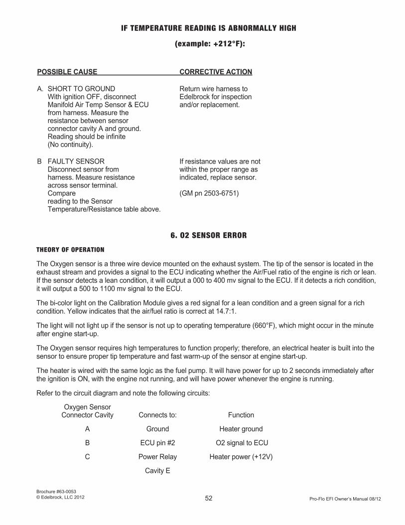
Pro-Flo EFI Owner’s Manual 08/12
Brochure #63-0053© Edelbrock, LLC 2012 52
IF TEMPERATURE READING IS ABNORMALLY HIGH
(example: +212°F):
POSSIBLE CAUSE CORRECTIVE ACTION
A. SHORT TO GROUND Return wire harness to With ignition OFF, disconnect Edelbrock for inspection Manifold Air Temp Sensor & ECU and/or replacement. from harness. Measure the resistance between sensor connector cavity A and ground. Reading should be infinite (No continuity).
B FAULTY SENSOR If resistance values are not Disconnect sensor from within the proper range as harness. Measure resistance indicated, replace sensor. across sensor terminal. Compare (GM pn 2503-6751) reading to the Sensor Temperature/Resistance table above.
6. O2 SENSOR ERROR
THEORY OF OPERATION
The Oxygen sensor is a three wire device mounted on the exhaust system. The tip of the sensor is located in the exhaust stream and provides a signal to the ECU indicating whether the Air/Fuel ratio of the engine is rich or lean. If the sensor detects a lean condition, it will output a 000 to 400 mv signal to the ECU. If it detects a rich condition, it will output a 500 to 1100 mv signal to the ECU.
The bi-color light on the Calibration Module gives a red signal for a lean condition and a green signal for a rich condition. Yellow indicates that the air/fuel ratio is correct at 14.7:1.
The light will not light up if the sensor is not up to operating temperature (660°F), which might occur in the minute after engine start-up.
The Oxygen sensor requires high temperatures to function properly; therefore, an electrical heater is built into the sensor to ensure proper tip temperature and fast warm-up of the sensor at engine start-up.
The heater is wired with the same logic as the fuel pump. It will have power for up to 2 seconds immediately after the ignition is ON, with the engine not running, and will have power whenever the engine is running.
Refer to the circuit diagram and note the following circuits:
Oxygen Sensor Connector Cavity Connects to: Function
A Ground Heater ground
B ECU pin #2 O2 signal to ECU
C Power Relay Heater power (+12V)
Cavity E
Pro-Flo EFI Owner’s Manual 08/12
Brochure #63-0053© Edelbrock, LLC 2012 53
TROUBLESHOOTING THE OXYGEN SENSOR AND CIRCUITS
NOTE: The Calibration Module will display O2 SENSOR ERROR only if there is an Oxygen sensor failure while the engine is running (at operating temperature) AND Closed Loop Fueling is turned ON. The O2 sensor connector pins “A” and “C” will have the same color wire, the middle “B” wire will be a different color wire.
The O2 Sensor can be tested for proper operation using a digital voltmeter. When the sensor is warmed up, measure voltage between Connector cavity B and ground. The output should read between 0 and 1 volt. As the air/fuel ratio decreases, the voltage will increase. At a ratio of 16:1, the voltage should be approximately 0.1. At a ratio of 11:1, the voltage should be approximately 0.9.
If an O2 SENSOR ERROR is present, note the state of the bi-colored light on the Calibration Module and proceed as follows:
BI-COLORED LIGHT IS DARK
POSSIBLE CAUSE CORRECTIVE ACTION
A CONNECTOR NOT CONNECTED Seat connector fully.
B. CONNECTOR DAMAGE Replace connector. at sensor or ECU
C. SENSOR TEMPERATURE TOO LOW Return wire harness to With ignition OFF, disconnect Edelbrock for inspection the Oxygen sensor. Measure and/or replacement. resistance between cavity A on wire harness and battery ground. Reading should be less than 0.4 ohms. Next, check for power. Measure voltage between cavity C on wire harness and ground. Reading should be at least 12V for up to 2 seconds after key ON.
D. SENSOR over tightened Make sure sensor is tightened screwed into sensor fitting. appropriately. CAUTION: Do not over-tighten.
E. FAULTY SENSOR Replace sensor.
F. Chip not installed or installed Chip is not sent with kit. incorrectly. Fuel pump chatters Send in chip card for chip. with key on. Cal Mod displays “No Communications”.
Note: Coated headers do not provide adequate grounding for the 0/2 sensor. Check this by measuring Ohms with a digital ohm meter between the cylinder head and the hex nut of the installed 0/2 sensor. Resistance should be less than 1 ohms.

Pro-Flo EFI Owner’s Manual 08/12
Brochure #63-0053© Edelbrock, LLC 2012 54
TROUBLESHOOTING START-UP PROBLEMS
ENGINE DOES NOT START
POSSIBLE CAUSE CORRECTIVE ACTION
A. DISTRIBUTOR FAILURE Examine distributor making sure the conversion has been done correctly. Check shutter wheel position. Remove a plug, ground to motor and check for spark. Make sure proper wire harness connections have been made.
B. LOW BATTERY VOLTAGE If voltage is less than 12V, Check battery voltage recharge or replace battery.
C. COIL IMPROPERLY CONNECTED Inspect all coil wires for proper connection.
D. IGNITION AMPLIFIER FAILURE Return ignition amplifier to Edelbrock for inspection and/or replacement.
E. Cal Module display goes blank Check Pink/black wire (With 3 Amp fuse) for a minimum while cranking. of 9 Volts while in the cranking and run positions.
F. Cal Module display goes “O” Check Pink/black wire (With 3 Amp fuse) for a minimum while cranking. of 9 Volts while in the cranking and run positions.
ENGINE STARTS, THEN STALLS
POSSIBLE CAUSE CORRECTIVE ACTION
A. NO FUEL PRESSURE Check pressure using the supplied dianostic tap and a fuel pressure gauge. Pressure should be 45-50 psi.
B FUEL PUMP IMPROPERLY INSTALLED Inspect pump to ensure it has not been installed backwards.
C. FUEL PUMP RELAY Check that pump relay has been installed according to instructions. IMPROPERLY CONNECTED
D. PUMP FUSE Check that pump fuse has been installed according to instructions. IMPROPERLY CONNECTED
E. MAIN SYSTEM Return wire harness to Edelbrock for inspection HARNESS PROBLEM and/or replacement.
F. FUEL LEAK Inspect entire fuel system from engine compartment to tank, and repair any leaks.
G FUEL PUMP SUCKING AIR Before starting engine, prime the fuel pump as described in Not primed the SYSTEM START-UP section of this manual.

Pro-Flo EFI Owner’s Manual 08/12
Brochure #63-0053© Edelbrock, LLC 2012 55
H. FILTER IMPROPERLY INSTALLED Inspect filter to ensure it has not been installed backwards. Install filter between pump and engine.
I. BLOCKED FUEL LINE Disconnect fuel line from filter and from fuel rail. Use compressed air to carefully loosen obstruction.
J. INCORRECT TIMING Check for accurate timing using a timing light.
K. AIR FUEL MIXTURE TOO RICH Check that fuel pressure regulator is allowing sufficient return fuel bypass.
L. PLUG WIRES NOT CONNECTED Inspect all spark plug wires for proper connection. Replace worn wires.
ENGINE STARTS, BUT RUNS ROUGH
POSSIBLE CAUSE CORRECTIVE ACTION
A. CAM INCORRECTLY INSTALLED Inspect cam to ensure it has been installed according to MFG’s instruction manual.
B. INCORRECT IGNITION TIMING Check for accurate timing using a timing light.
C. INCORRECT IGNITION PHASING Inspect for correct plug wire connections. Check distributor for correct shutter wheel position.
D. INJECTORS NOT CONNECTED Inspect all injector connectors for proper connection.
E. INCORRECT FIRING ORDER Inspect plug wire routing for the correct firing order.
WATER LEAKS
POSSIBLE CAUSE CORRECTIVE ACTION
A GASKET FAILURE Inspect gaskets. Replace old gaskets.
B. SEALANT FAILURE Use the proper sealant recommended in the instructions.
VACUUM LEAKS
POSSIBLE CAUSE CORRECTIVE ACTION
A. HOSE FAILURE Inspect all hoses for correct re-connection. Replace all questionable hoses.
B. GASKET FAILURE Inspect manifold gaskets. Replace old gaskets.
Pro-Flo EFI Owner’s Manual 08/12
Brochure #63-0053© Edelbrock, LLC 2012 56
NOTE: Use the correct Edelbrock, OEM replacement, or Fel-Pro Printoseal gaskets.
C. FAILURE TO RE-TORQUE MANIFOLD Inspect manifold and torque according to the instructions in this manual.
FOULED PLUGS AND OIL LEAKS
POSSIBLE CAUSE CORRECTIVE ACTION
A. FAILURE TO RE-TORQUE MANIFOLD Inspect manifold and torque according to the instructions in this manual.
B. GASKET FAILURE Inspect gaskets for correctness and wear. Replace old gaskets.
C. SEALANT FAILURE Use the proper sealant recommended in the instructions.
D. END SEAL SLIPPAGE Inspect end seals for a sufficient amount of the correct RTV sealant.
POOR MILEAGE
POSSIBLE CAUSE CORRECTIVE ACTION
A. INCORRECT DISTRIBUTOR CURVES Inspect distributor to ensure that mechanical advance has been locked out. Inspect fuel and spark calibrations with Calibration Module, modifying for conditions if necessary.
B. INCORRECT AUTOMATIC Adjust shift points asdescribed in the TRANSMISSION SHIFT POINTS INTRODUCTION of this manual.
C. VACUUM HOSE LEAK Inspect all hoses for correct re-connection. Replace all questionable hoses.
D. INCORRECT TIMING Check for accurate timing using a timing light.
E. RESTRICTED AIR FLOW Inspect air cleaner element, replacing if necessary.

Pro-Flo EFI Owner’s Manual 08/12
Brochure #63-0053© Edelbrock, LLC 2012 57
Wiri
ng D
iagr
am#3
500,
350
3, 3
507,
355
0, 3
551
Fuel
Pum
p
ECU
Cal
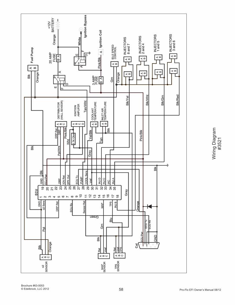
Pro-Flo EFI Owner’s Manual 08/12
Brochure #63-0053© Edelbrock, LLC 2012 58
Wiri
ng D
iagr
am#3
521
Fuel
Pum
pEC
U
Cal
Igni
tion
Byp
ass
Igni
tion
Coi
l
Whi
te

Pro-Flo EFI Owner’s Manual 08/12
Brochure #63-0053© Edelbrock, LLC 2012 59
Wiri
ng D
iagr
am#3
541
Fuel
Pum
pEC
U
Cal
Igni
tion
Byp
ass
Igni
tion
Coi
l
Whi
te

Pro-Flo EFI Owner’s Manual 08/12
Brochure #63-0053© Edelbrock, LLC 2012 60
NOTES

Brochure #63-0053
Edelbrock, LLC
2700 California Street
Torrance, CA 90503
Office Telephone: (310) 781-2222
Tech Telephone only: (800) 416-8628
Tech Fax (310) 972-2730
Email: [email protected]