ecr ion sources-past, present and future - applied physics...
TRANSCRIPT
Claude Lyneis LBNL4/18/2014 Columbia University
ECR Ion Sources-Past, Present and Future
• Production of Highly Charged Ion Beams
• Physics
• Technology
• Challenges
• Recent experiments at Berkeley
Claude Lyneis LBNL4/18/2014 Columbia University
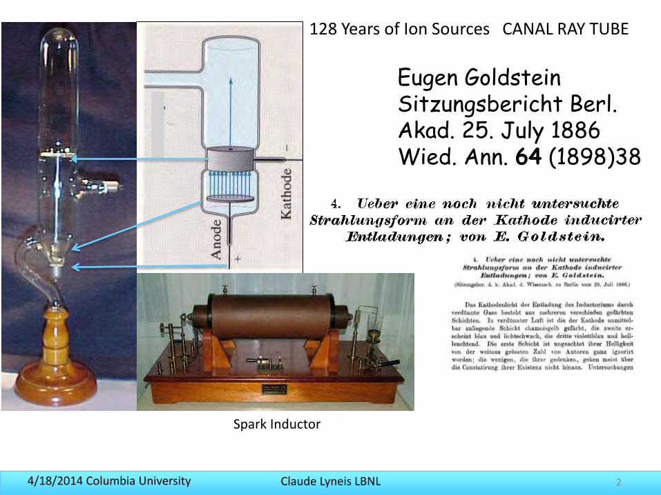
Spark Inductor
Eugen Goldstein Sitzungsbericht Berl. Akad. 25. July 1886Wied. Ann. 64 (1898)38
128 Years of Ion Sources CANAL RAY TUBE
2
Claude Lyneis LBNL4/18/2014 Columbia University 3
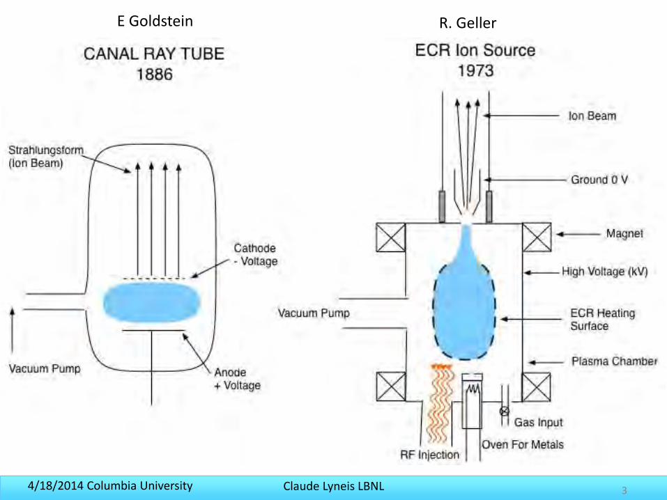
E Goldstein R. Geller
Claude Lyneis LBNL4/18/2014 Columbia University 4
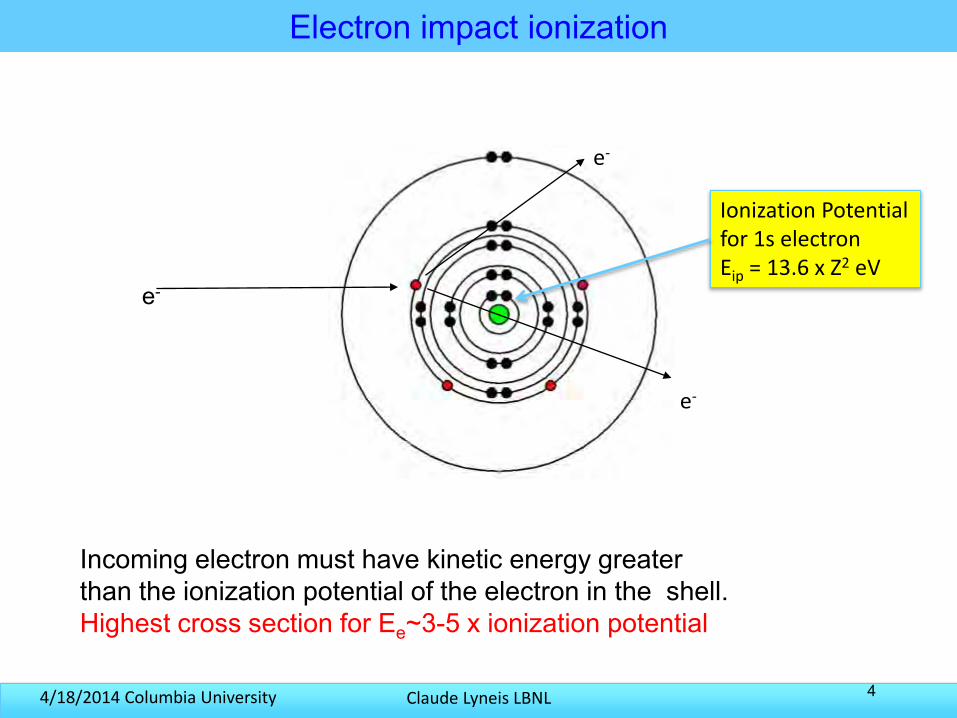
Electron impact ionization
e-
e-
e-
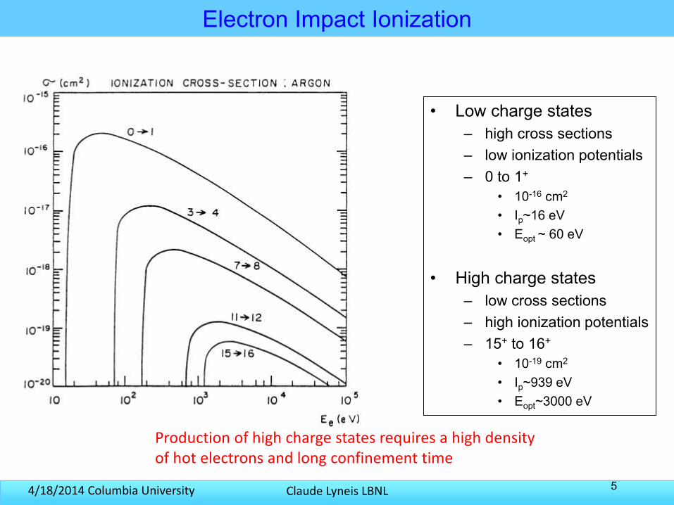
Incoming electron must have kinetic energy greaterthan the ionization potential of the electron in the shell.Highest cross section for Ee~3-5 x ionization potential
Ionization Potentialfor 1s electronEip = 13.6 x Z2 eV
Claude Lyneis LBNL4/18/2014 Columbia University 5
Electron Impact Ionization
• Low charge states– high cross sections– low ionization potentials– 0 to 1+
• 10-16 cm2
• Ip~16 eV• Eopt ~ 60 eV
• High charge states– low cross sections– high ionization potentials– 15+ to 16+
• 10-19 cm2
• Ip~939 eV• Eopt~3000 eV
Production of high charge states requires a high density of hot electrons and long confinement time
Claude Lyneis LBNL4/18/2014 Columbia University
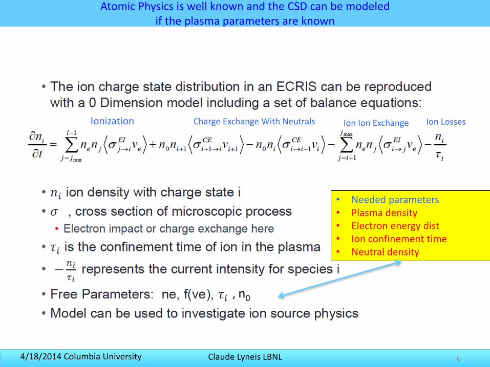
Atomic Physics is well known and the CSD can be modeledif the plasma parameters are known
6
• Needed parameters • Plasma density• Electron energy dist• Ion confinement time• Neutral density
, n0
Ionization Charge Exchange With Neutrals Ion Ion Exchange Ion Losses
Claude Lyneis LBNL4/18/2014 Columbia University 7
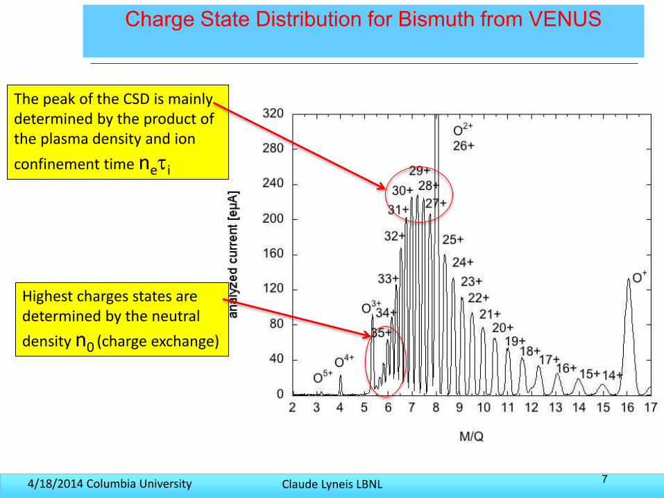
Charge State Distribution for Bismuth from VENUS
The peak of the CSD is mainly determined by the product of the plasma density and ion
confinement time neti
Highest charges states aredetermined by the neutral
density n0 (charge exchange)
Claude Lyneis LBNL4/18/2014 Columbia University
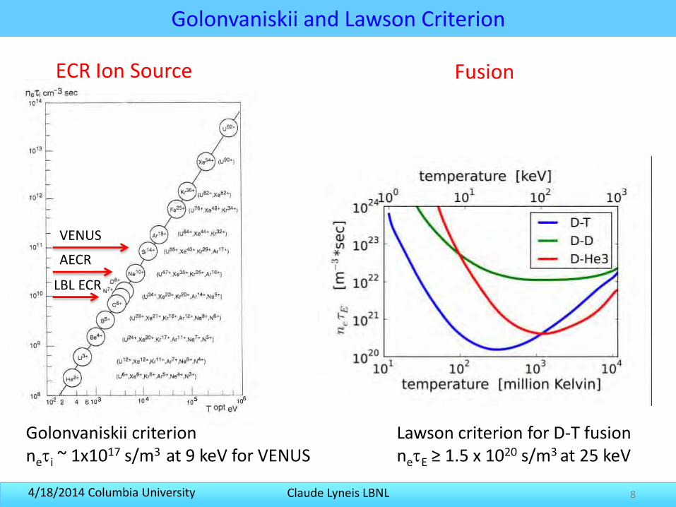
Golonvaniskii and Lawson Criterion
8
Lawson criterion for D-T fusionnetE ≥ 1.5 x 10²⁰ s/m3 at 25 keV
VENUS
Golonvaniskii criterionneti ~ 1x10¹⁷ s/m3 at 9 keV for VENUS
FusionECR Ion Source
AECR
LBL ECR
Claude Lyneis LBNL4/18/2014 Columbia University 9
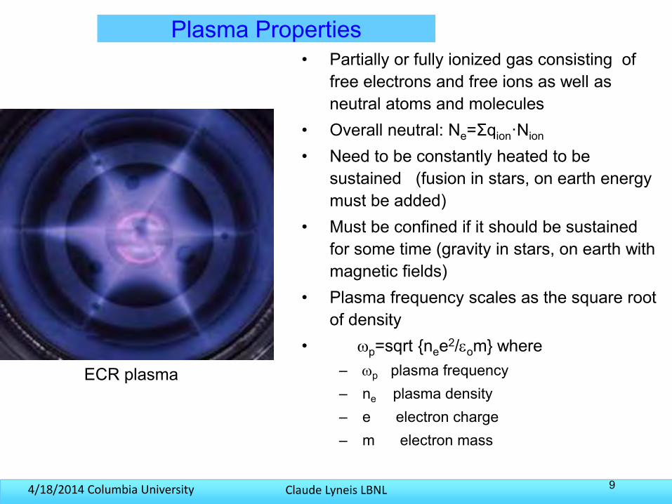
Plasma Properties• Partially or fully ionized gas consisting of
free electrons and free ions as well as neutral atoms and molecules
• Overall neutral: Ne=Σqion·Nion
• Need to be constantly heated to be sustained (fusion in stars, on earth energy must be added)
• Must be confined if it should be sustained for some time (gravity in stars, on earth with magnetic fields)
• Plasma frequency scales as the square root of density
• p=sqrt {nee2/om} where– p plasma frequency– ne plasma density– e electron charge– m electron mass
ECR plasma
Claude Lyneis LBNL4/18/2014 Columbia University 10
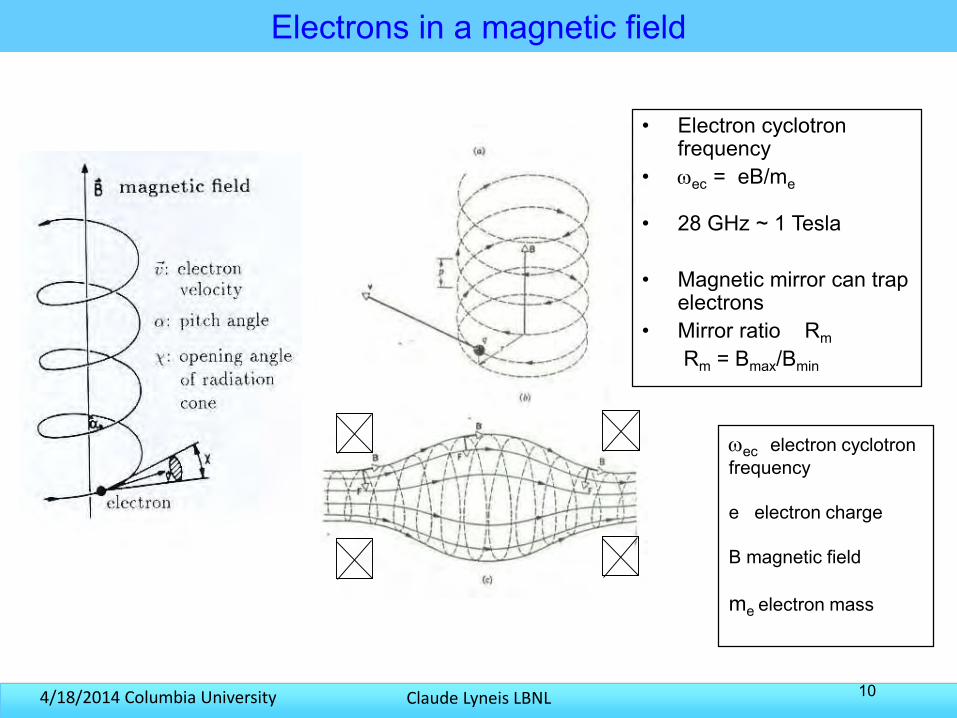
Electrons in a magnetic field
• Electron cyclotron frequency
• ec = eB/me
• 28 GHz ~ 1 Tesla
• Magnetic mirror can trap electrons
• Mirror ratio RmRm = Bmax/Bmin
ec electron cyclotron frequency
e electron charge
B magnetic field
me electron mass
Claude Lyneis LBNL4/18/2014 Columbia University 11
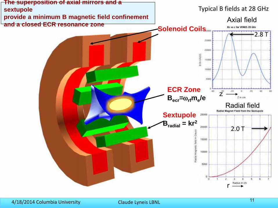
Solenoid Coils
Sextupole
Bradial = kr2
The superposition of axial mirrors and a
sextupole
provide a minimum B magnetic field confinement
and a closed ECR resonance zone
ECR Zone
Becr=rfme/ez
r
Axial field
Radial field
2.8 T
2.0 T
Typical B fields at 28 GHz
Claude Lyneis LBNL4/18/2014 Columbia University
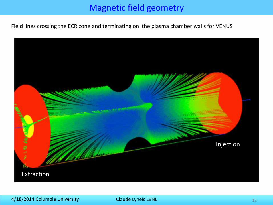
Magnetic field geometry
12
Field lines crossing the ECR zone and terminating on the plasma chamber walls for VENUS
Extraction
Injection
Claude Lyneis LBNL4/18/2014 Columbia University
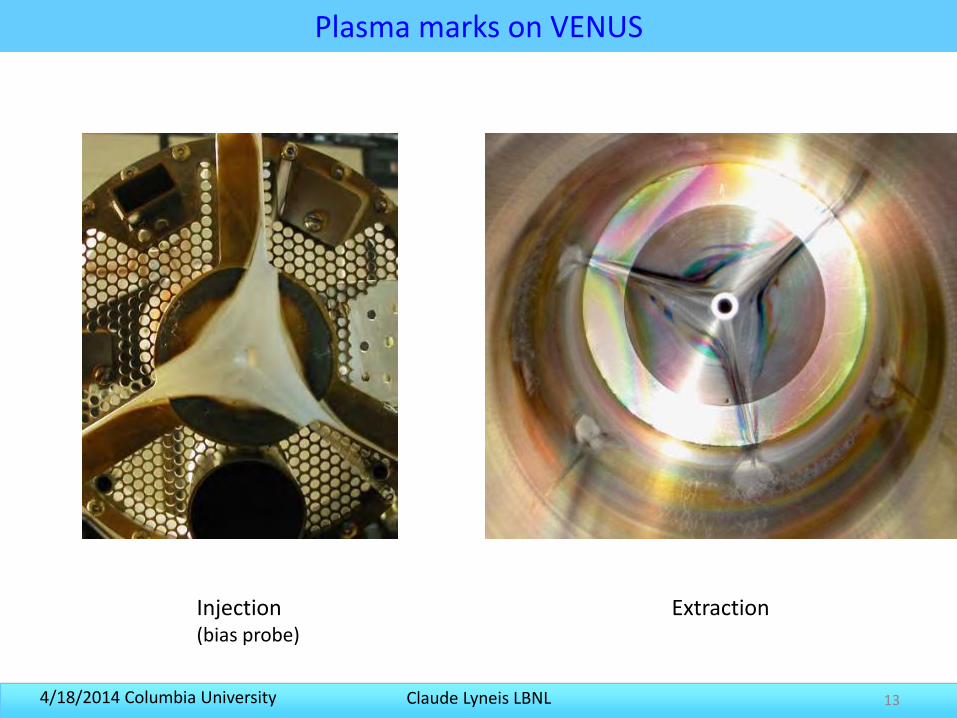
Plasma marks on VENUS
13
Injection(bias probe)
Extraction
Claude Lyneis LBNL4/18/2014 Columbia University 14
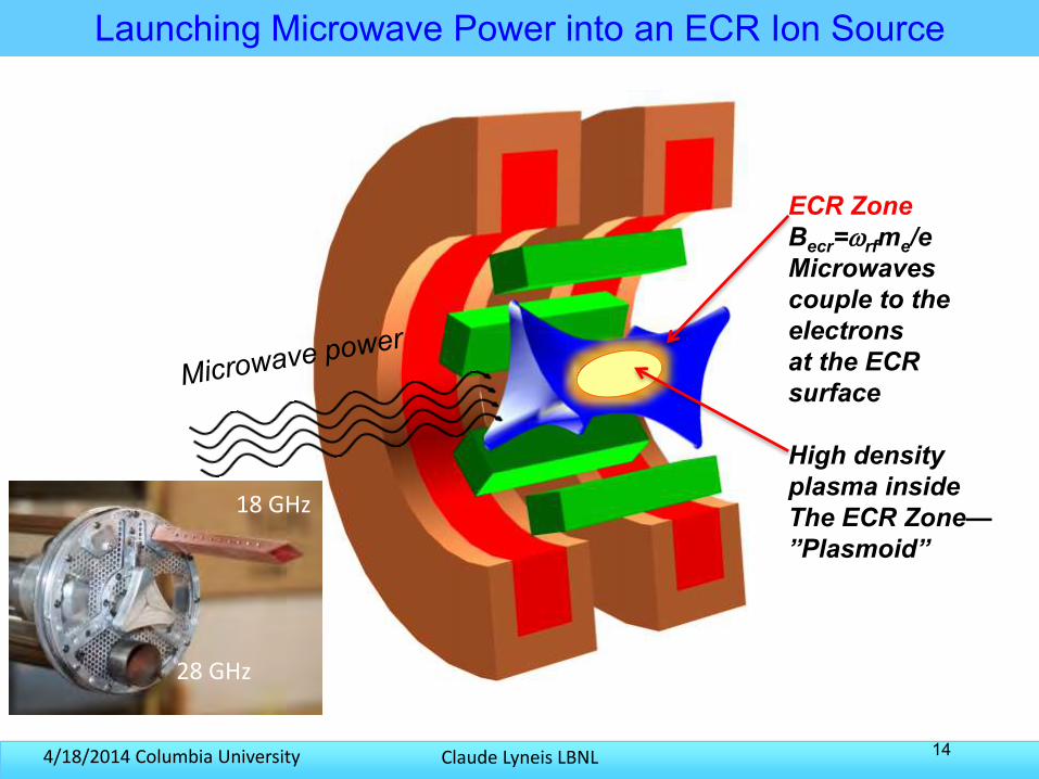
Typical B fields at 28 GHzLaunching Microwave Power into an ECR Ion Source
ECR ZoneBecr=rfme/eMicrowavescouple to the electronsat the ECR surface
High density plasma insideThe ECR Zone—”Plasmoid”
18 GHz
28 GHz
Claude Lyneis LBNL4/18/2014 Columbia University 15
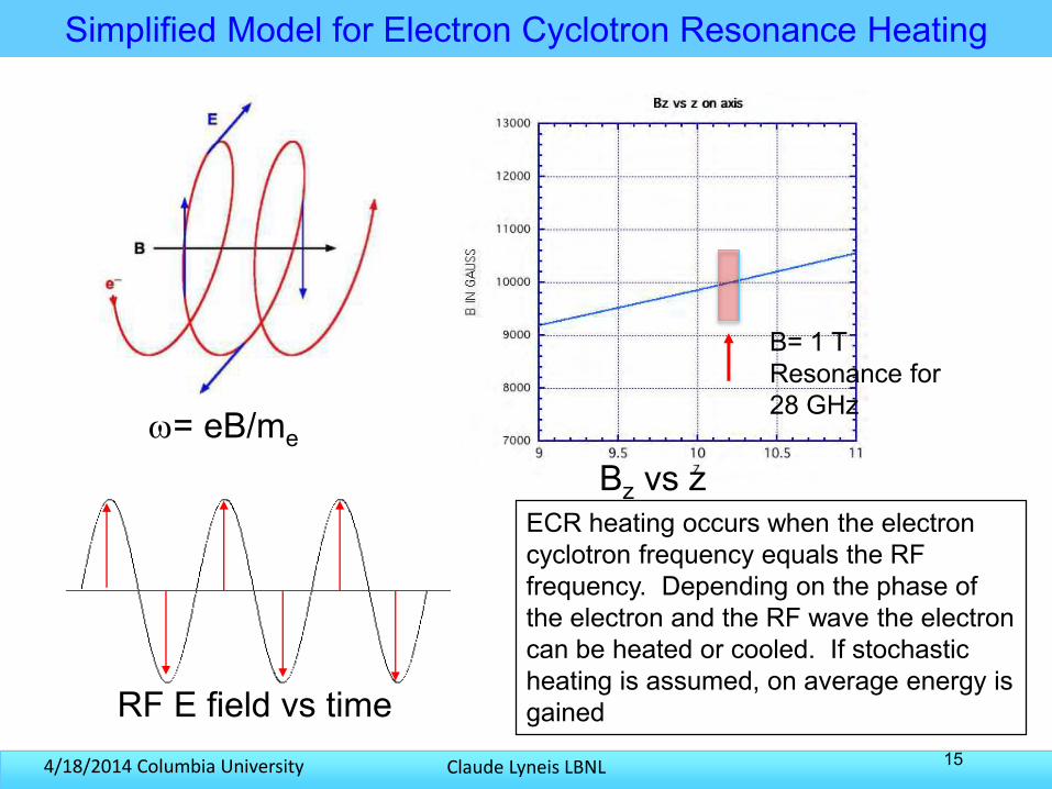
Simplified Model for Electron Cyclotron Resonance Heating
= eB/me
Bz vs z
RF E field vs time
B= 1 TResonance for28 GHz
ECR heating occurs when the electron cyclotron frequency equals the RF frequency. Depending on the phase of the electron and the RF wave the electron can be heated or cooled. If stochastic heating is assumed, on average energy is gained
Claude Lyneis LBNL4/18/2014 Columbia University
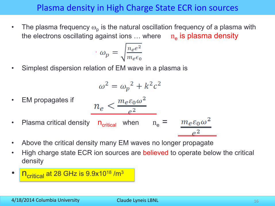
Plasma density in High Charge State ECR ion sources
• The plasma frequency p is the natural oscillation frequency of a plasma with the electrons oscillating against ions … where ne is plasma density
• Simplest dispersion relation of EM wave in a plasma is
• EM propagates if
• Plasma critical density ncritical when ne =
• Above the critical density many EM waves no longer propagate• High charge state ECR ion sources are believed to operate below the critical
density
• ncritical at 28 GHz is 9.9x10¹⁸ /m3
16
Claude Lyneis LBNL4/18/2014 Columbia University 17
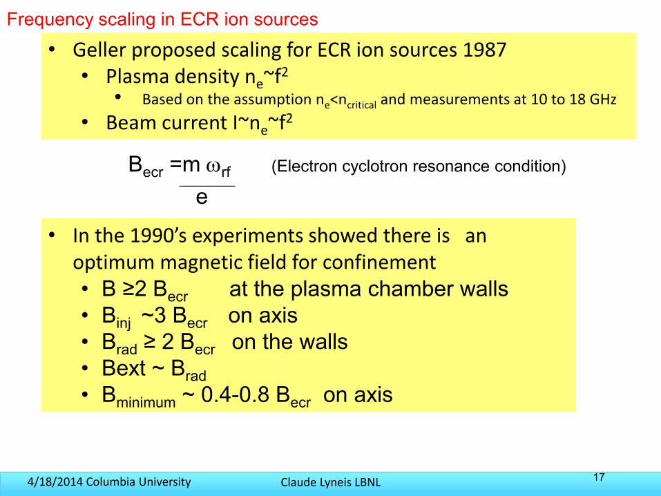
Becr =m rf
e
Frequency scaling in ECR ion sources
(Electron cyclotron resonance condition)
• Geller proposed scaling for ECR ion sources 1987• Plasma density ne~f2
• Based on the assumption ne<ncritical and measurements at 10 to 18 GHz
• Beam current I~ne~f2
• In the 1990’s experiments showed there is an optimum magnetic field for confinement• B ≥2 Becr at the plasma chamber walls• Binj ~3 Becr on axis• Brad ≥ 2 Becr on the walls• Bext ~ Brad• Bminimum ~ 0.4-0.8 Becr on axis
Claude Lyneis LBNL4/18/2014 Columbia University 18
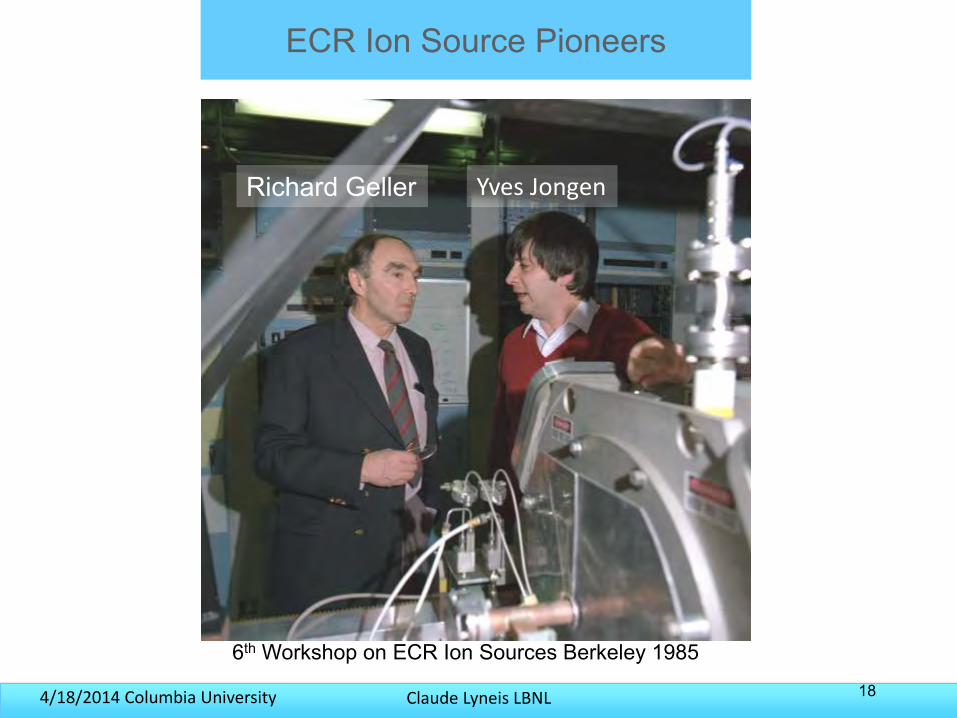
ECR Ion Source Pioneers
Richard Geller Yves Jongen
6th Workshop on ECR Ion Sources Berkeley 1985
Claude Lyneis LBNL4/18/2014 Columbia University 19
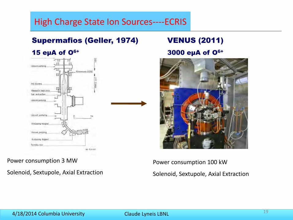
High Charge State Ion Sources----ECRIS
Supermafios (Geller, 1974)
15 eµA of O6+
VENUS (2011)
3000 eµA of O6+
Power consumption 3 MW
Solenoid, Sextupole, Axial Extraction
Power consumption 100 kW
Solenoid, Sextupole, Axial Extraction
Claude Lyneis LBNL4/18/2014 Columbia University 20
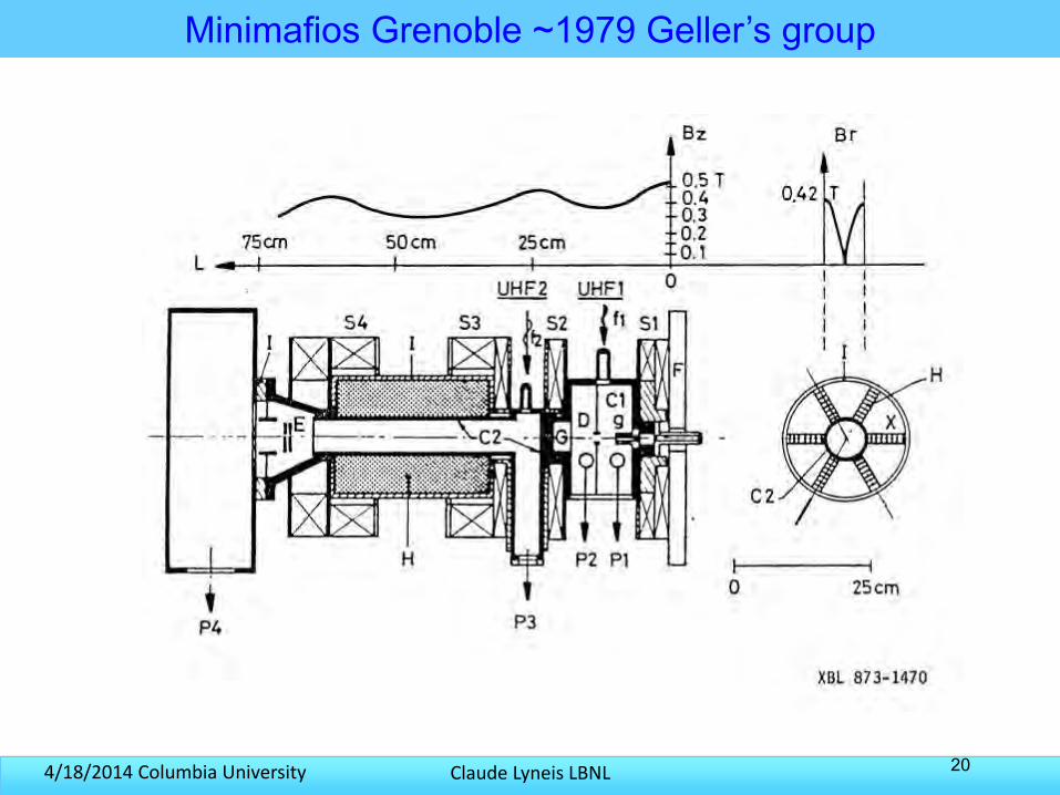
Minimafios Grenoble ~1979 Geller’s group
Claude Lyneis LBNL4/18/2014 Columbia University 21
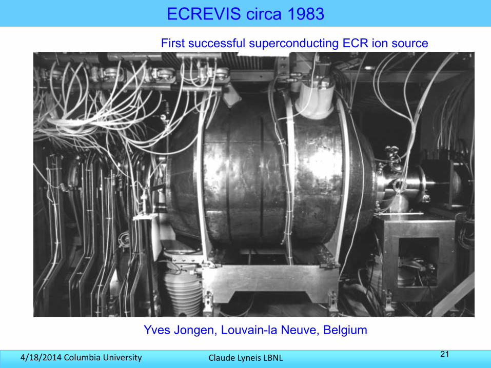
ECREVIS circa 1983First successful superconducting ECR ion source
Yves Jongen, Louvain-la Neuve, Belgium
Claude Lyneis LBNL4/18/2014 Columbia University
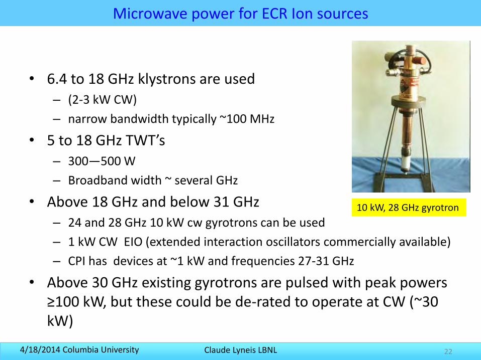
Microwave power for ECR Ion sources
• 6.4 to 18 GHz klystrons are used – (2-3 kW CW)
– narrow bandwidth typically ~100 MHz
• 5 to 18 GHz TWT’s – 300—500 W
– Broadband width ~ several GHz
• Above 18 GHz and below 31 GHz– 24 and 28 GHz 10 kW cw gyrotrons can be used
– 1 kW CW EIO (extended interaction oscillators commercially available)
– CPI has devices at ~1 kW and frequencies 27-31 GHz
• Above 30 GHz existing gyrotrons are pulsed with peak powers ≥100 kW, but these could be de-rated to operate at CW (~30 kW)
22
10 kW, 28 GHz gyrotron
Claude Lyneis LBNL4/18/2014 Columbia University 23
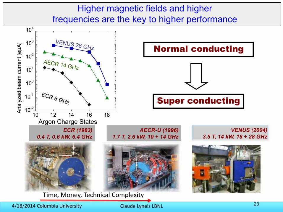
Higher magnetic fields and higher frequencies are the key to higher performance
Normal conducting
Super conducting
10-2
10-1
100
101
102
103
104
10 12 14 16 18Ana
lyze
d be
am c
urre
nt [e
µA]
Argon Charge StatesECR (1983)
0.4 T, 0.6 kW, 6.4 GHzAECR-U (1996)
1.7 T, 2.6 kW, 10 + 14 GHzVENUS (2004)
3.5 T, 14 kW, 18 + 28 GHz
Time, Money, Technical Complexity
Claude Lyneis LBNL4/18/2014 Columbia University
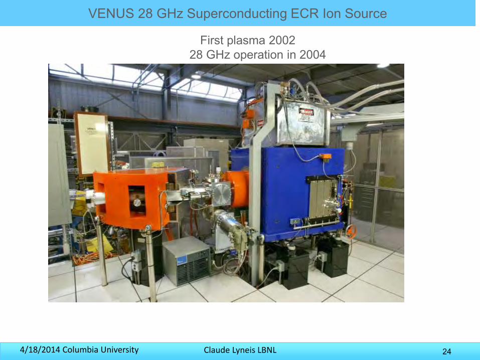
VENUS 28 GHz Superconducting ECR Ion Source
24
First plasma 200228 GHz operation in 2004
Claude Lyneis LBNL4/18/2014 Columbia University
VENUS Magnet Development and Performance
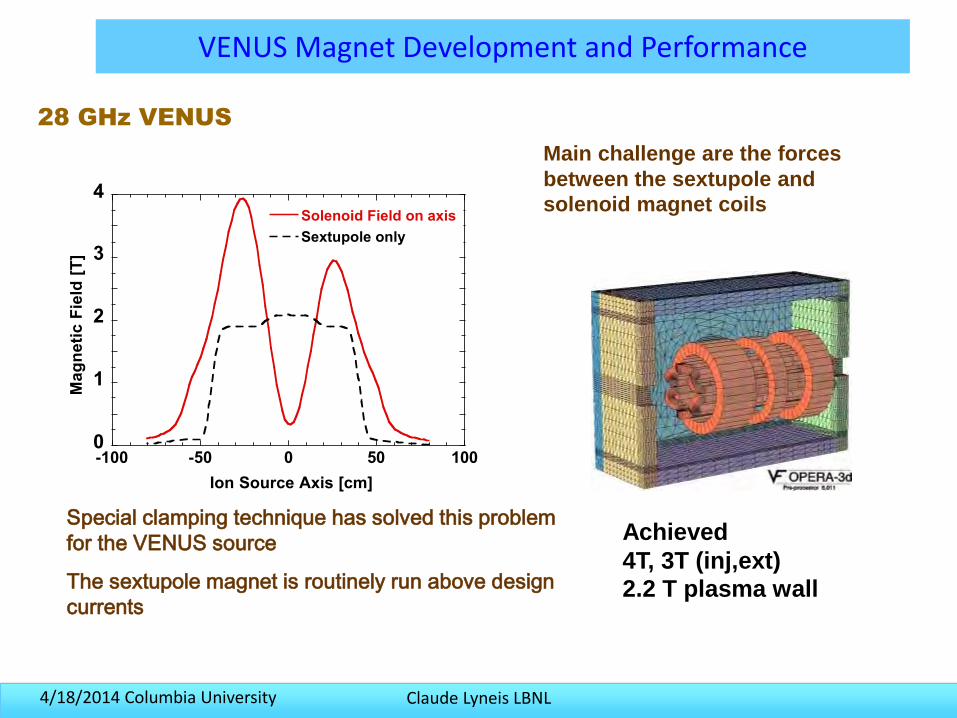
28 GHz VENUS
Main challenge are the forces
between the sextupole and
solenoid magnet coils
Special clamping technique has solved this problem
for the VENUS source
The sextupole magnet is routinely run above design
currents
Achieved
4T, 3T (inj,ext)
2.2 T plasma wall
0
1
2
3
4
-100 -50 0 50 100
Solenoid Field on axis
Sextupole only
Ma
gn
eti
c F
ield
[T
]
Ion Source Axis [cm]
Claude Lyneis LBNL4/18/2014 Columbia University 26
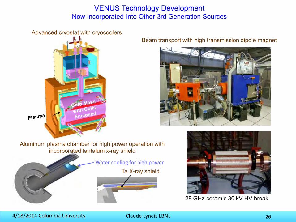
Advanced cryostat with cryocoolersBeam transport with high transmission dipole magnet
Ta X-ray shield
VENUS Technology DevelopmentNow Incorporated Into Other 3rd Generation Sources
Aluminum plasma chamber for high power operation with incorporated tantalum x-ray shield
Water cooling for high power
28 GHz ceramic 30 kV HV break
Claude Lyneis LBNL4/18/2014 Columbia University
Overview of VENUS
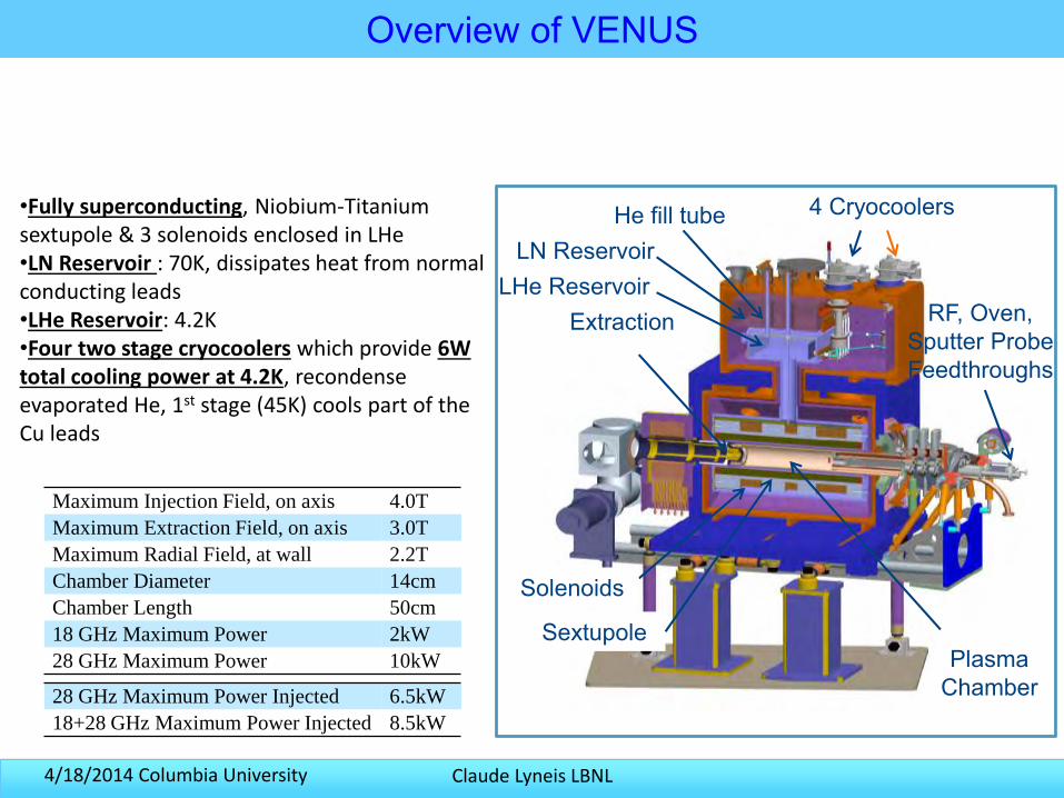
Extraction
4 CryocoolersHe fill tube
Sextupole
LN Reservoir
Solenoids
•Fully superconducting, Niobium-Titanium sextupole & 3 solenoids enclosed in LHe•LN Reservoir : 70K, dissipates heat from normal conducting leads•LHe Reservoir: 4.2K•Four two stage cryocoolers which provide 6W total cooling power at 4.2K, recondenseevaporated He, 1st stage (45K) cools part of the Cu leads
Maximum Injection Field, on axis 4.0T
Maximum Extraction Field, on axis 3.0T
Maximum Radial Field, at wall 2.2T
Chamber Diameter 14cm
Chamber Length 50cm
18 GHz Maximum Power 2kW
28 GHz Maximum Power 10kW
28 GHz Maximum Power Injected 6.5kW
18+28 GHz Maximum Power Injected 8.5kW
Plasma Chamber
RF, Oven, Sputter Probe Feedthroughs
LHe Reservoir
Claude Lyneis LBNL4/18/2014 Columbia University
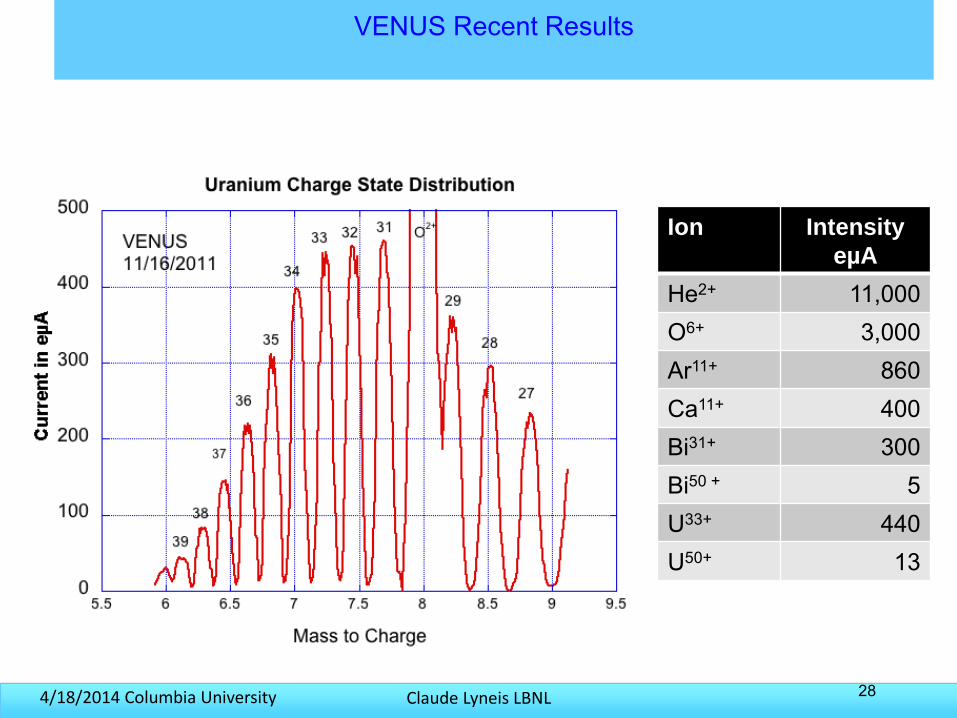
VENUS Recent Results
28
Ion Intensity
eµA
He2+ 11,000O6+ 3,000Ar11+ 860Ca11+ 400Bi31+ 300Bi50 + 5U33+ 440U50+ 13
Claude Lyneis LBNL4/18/2014 Columbia University 29
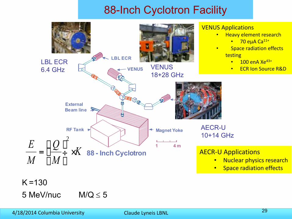
88-Inch Cyclotron Facility
4 m1
88 - Inch Cyclotron
External
Beam line
RF Tank Magnet Yoke
AECR-U
VENUS
LBL ECRLBL ECR 6.4 GHz
AECR-U10+14 GHz
VENUS 18+28 GHz
KM
Q
M
E×÷
ø
öçè
æ=2
K =1305 MeV/nuc M/Q 5
VENUS Applications• Heavy element research
• 70 eµA Ca11+
• Space radiation effects testing
• 100 enA Xe43+
• ECR Ion Source R&D
AECR-U Applications• Nuclear physics research• Space radiation effects
Claude Lyneis LBNL4/18/2014 Columbia University
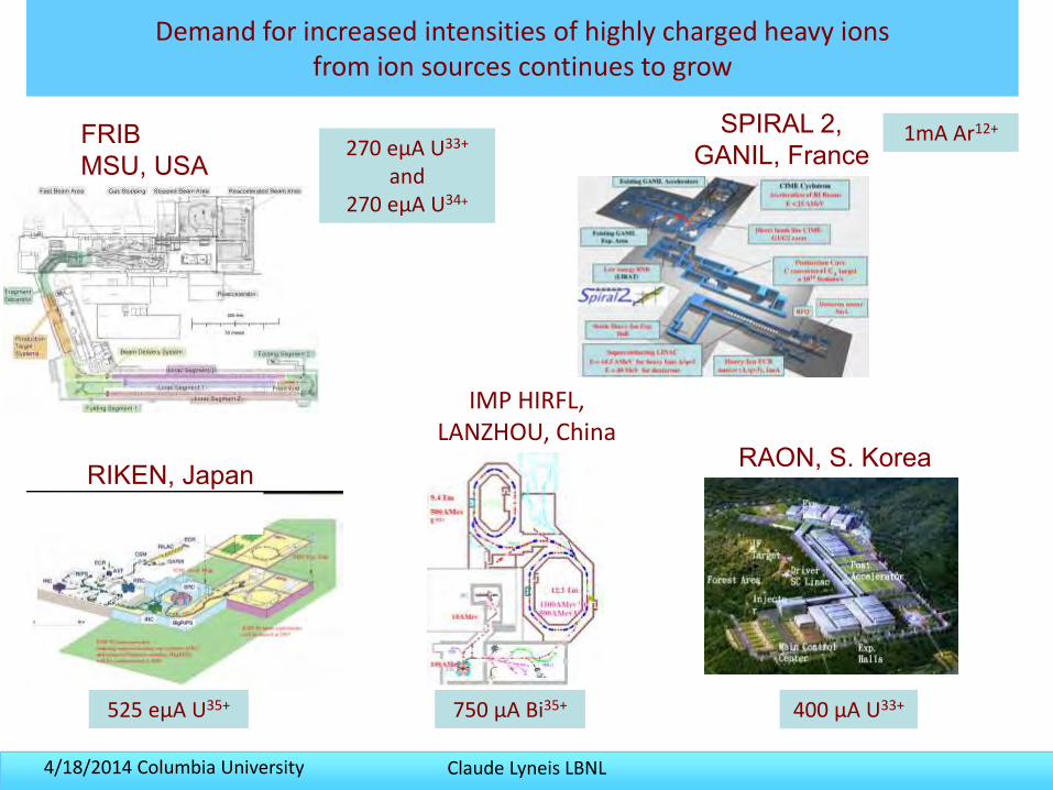
Demand for increased intensities of highly charged heavy ions from ion sources continues to grow
RIKEN, Japan
FRIBMSU, USA
SPIRAL 2, GANIL, France
525 eµA U35+
1mA Ar12+
270 eµA U33+
and 270 eµA U34+
750 µA Bi35+
IMP HIRFL, LANZHOU, China
RAON, S. Korea
400 µA U33+
Claude Lyneis LBNL4/18/2014 Columbia University
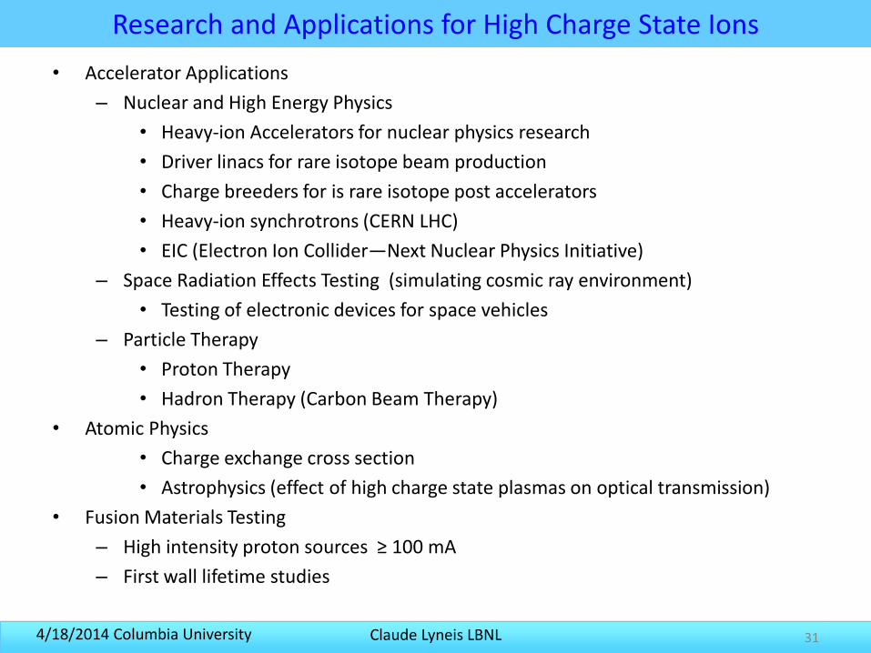
Research and Applications for High Charge State Ions
• Accelerator Applications
– Nuclear and High Energy Physics
• Heavy-ion Accelerators for nuclear physics research
• Driver linacs for rare isotope beam production
• Charge breeders for is rare isotope post accelerators
• Heavy-ion synchrotrons (CERN LHC)
• EIC (Electron Ion Collider—Next Nuclear Physics Initiative)
– Space Radiation Effects Testing (simulating cosmic ray environment)
• Testing of electronic devices for space vehicles
– Particle Therapy
• Proton Therapy
• Hadron Therapy (Carbon Beam Therapy)
• Atomic Physics
• Charge exchange cross section
• Astrophysics (effect of high charge state plasmas on optical transmission)
• Fusion Materials Testing
– High intensity proton sources ≥ 100 mA
– First wall lifetime studies
31
Claude Lyneis LBNL4/18/2014 Columbia University 32
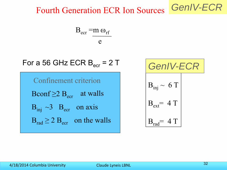
Becr =m wrf
e
Confinement criterion
Bconf ≥2 Becr
Binj ~3 Becr on axis
Brad ≥ 2 Becr on the walls
at wallsBinj ~ 6 T
Bext= 4 T
Brad= 4 T
GenIV-ECR
Fourth Generation ECR Ion Sources GenIV-ECR
For a 56 GHz ECR Becr = 2 T
Claude Lyneis LBNL4/18/2014 Columbia University
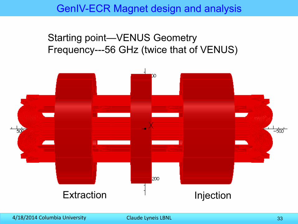
GenIV-ECR Magnet design and analysis
33
Starting point—VENUS GeometryFrequency---56 GHz (twice that of VENUS)
Extraction Injection
Claude Lyneis LBNL4/18/2014 Columbia University 34
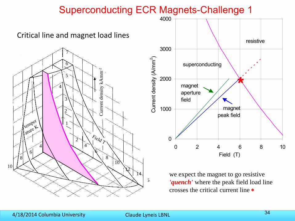
Critical line and magnet load lines
16
0
1000
2000
3000
4000
0 2 4 6 8 10Field (T)
Cur
rent
den
sity
(A/m
m2 )
magnet peak field
superconducting
resistive
magnet aperture field
we expect the magnet to go resistive
'quench' where the peak field load line
crosses the critical current line
*
8
6
42 2
4
6
810
1214
1
2
3
4
5
6
7
Curr
ent
den
sity
kA
mm
-2
10
Superconducting ECR Magnets-Challenge 1
Claude Lyneis LBNL4/18/2014 Columbia University
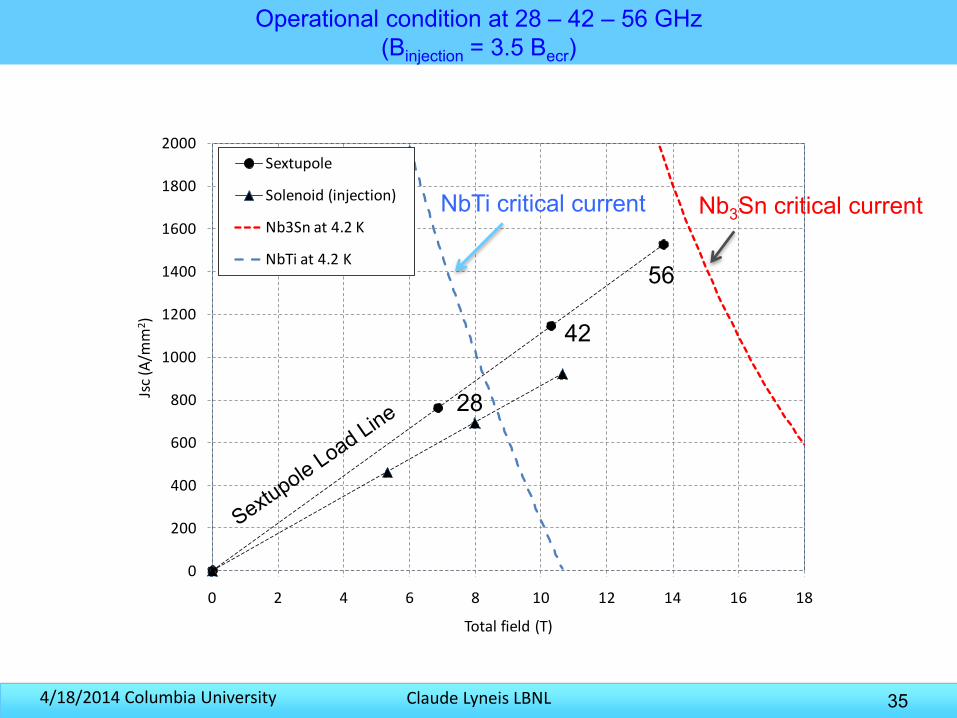
Operational condition at 28 – 42 – 56 GHz(Binjection = 3.5 Becr)
35
0
200
400
600
800
1000
1200
1400
1600
1800
2000
0 2 4 6 8 10 12 14 16 18
Jsc
(A/m
m2)
Total field (T)
Sextupole
Solenoid (injection)
Nb3Sn at 4.2 K
NbTi at 4.2 K
Nb3Sn critical currentNbTi critical current
56
42
28
Claude Lyneis LBNL4/18/2014 Columbia University
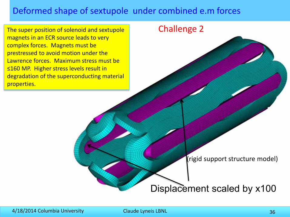
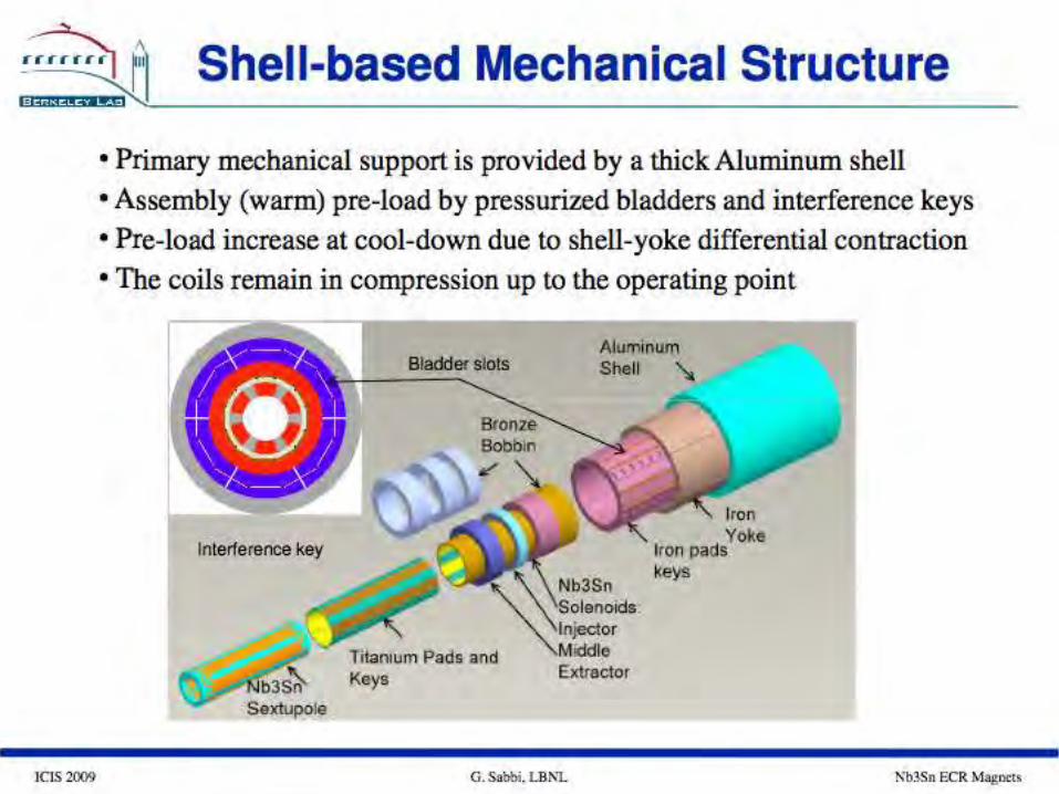
Deformed shape of sextupole under combined e.m forces
36
Displacement scaled by x100
(rigid support structure model)
The super position of solenoid and sextupolemagnets in an ECR source leads to very complex forces. Magnets must be prestressed to avoid motion under the Lawrence forces. Maximum stress must be ≤160 MP. Higher stress levels result in degradation of the superconducting material properties.
Challenge 2
Claude Lyneis LBNL4/18/2014 Columbia UniversityClaude Lyneis U.C. Nuclear Engineering 282 10/5/09 37
Claude Lyneis LBNL4/18/2014 Columbia University
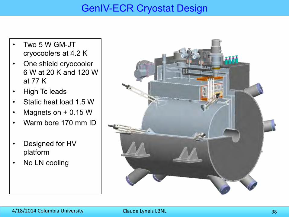
GenIV-ECR Cryostat Design
• Two 5 W GM-JT cryocoolers at 4.2 K
• One shield cryocooler 6 W at 20 K and 120 W at 77 K
• High Tc leads• Static heat load 1.5 W• Magnets on + 0.15 W• Warm bore 170 mm ID
• Designed for HV platform
• No LN cooling
38
Claude Lyneis LBNL4/18/2014 Columbia University
RF coupling, plasma density and diagnostics
• In the ECR community, much of the experimental knowledge is based to the properties of the extracted ion beams, such as charge state distributions, extracted current intensities and time evolution of the charge state distributions
• However the ions are relatively passive participants, they are cold ~ a few eV, they don’t couple to the RF heating and the instabilities are from the plasma electrons
• To improve our understanding of ECR ion source plasma, we need to focus on the electron dynamics and develop/apply diagnostics to study the electrons.
• Questions:
– How strong is the RF coupling/damping in an ECR plasma chamber?
– What limits the plasma density?
– How can we get a handle on these questions?
39
Claude Lyneis LBNL4/18/2014 Columbia University
RF coupling models
• The plasma chamber can be considered a multimode cavity filled with a lossy material.– Typical ECR plasma chambers are highly over-moded, so the
eigenmodes of the cavity are very closely spaced
– Models often assume a single mode is excited, but except at very low densities the modes will overlap
– Models often neglect the plasma loading and assume the chamber has a Q0 similar to an empty chamber ~2000 to 5000 would be typical of an aluminum chamber at vacuum
• The few pass approach assumes strong damping for the RF launched from in injection waveguide– Single pass damping is not well know and depends on density
– RF not adsorbed in the first pass is then reflected by the chamber walls—Complex to model
40
Claude Lyneis LBNL4/18/2014 Columbia University
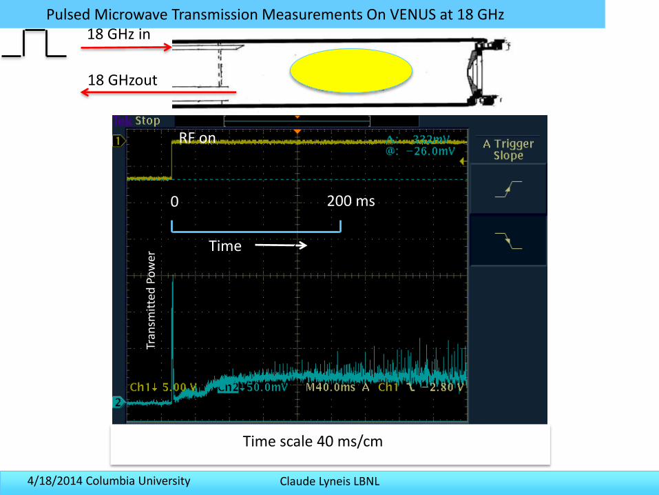
Pulsed Microwave Transmission Measurements On VENUS at 18 GHz
0 200 ms
Time
RF onTr
ansm
itte
d P
ow
er
Time scale 40 ms/cmTime scall 40 ms/cmTime scale 40 ms/cm
18 GHz in
18 GHzout
Claude Lyneis LBNL4/18/2014 Columbia University
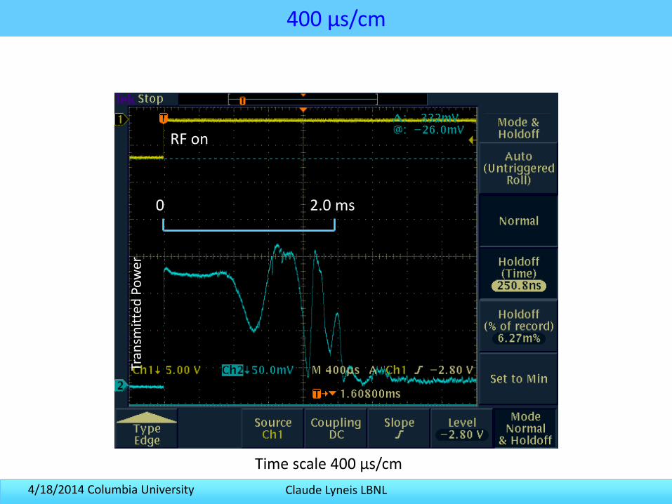
400 µs/cm
0 2.0 ms
Tran
smit
ted
Po
wer
RF on
Time scale 400 µs/cm
Claude Lyneis LBNL4/18/2014 Columbia University
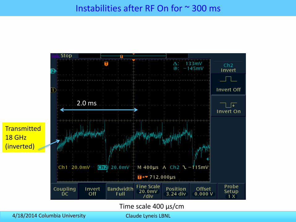
Instabilities after RF On for ~ 300 ms
Time scale 400 µs/cm
Transmitted18 GHz(inverted)
2.0 ms
Claude Lyneis LBNL4/18/2014 Columbia University
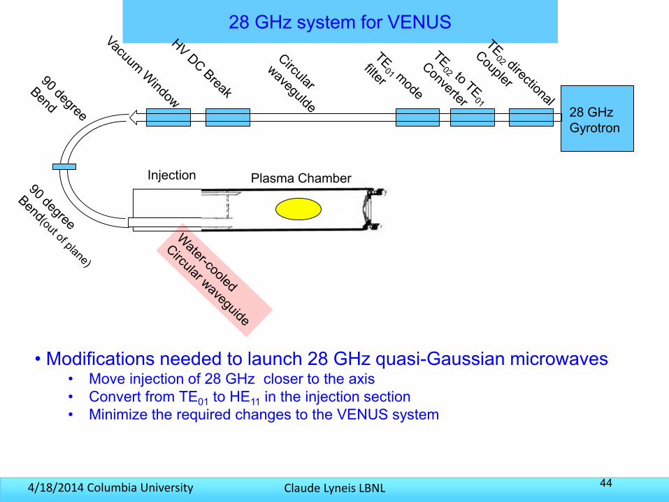
28 GHz system for VENUS
44
28 GHz Gyrotron
Plasma ChamberInjection
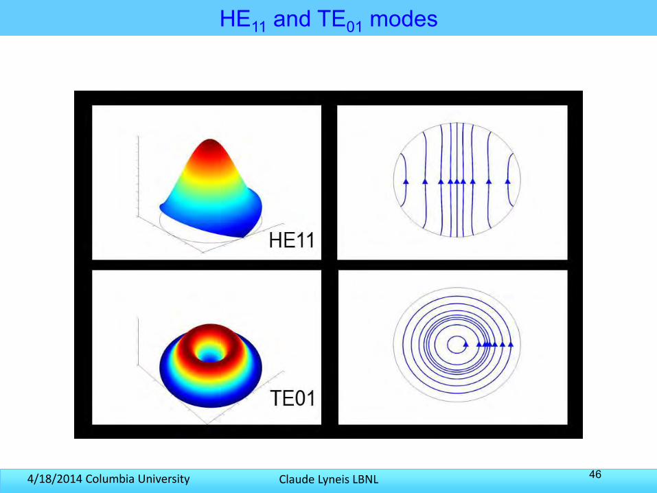
• Modifications needed to launch 28 GHz quasi-Gaussian microwaves• Move injection of 28 GHz closer to the axis• Convert from TE01 to HE11 in the injection section• Minimize the required changes to the VENUS system
Claude Lyneis LBNL4/18/2014 Columbia University
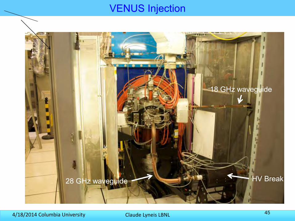
VENUS Injection
45
28 GHz waveguide
18 GHz waveguide
HV Break
Claude Lyneis LBNL4/18/2014 Columbia University
HE11 and TE01 modes
46
Claude Lyneis LBNL4/18/2014 Columbia University
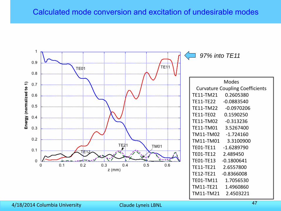
Calculated mode conversion and excitation of undesirable modes
47
Modes Curvature Coupling Coefficients
TE11-TM21 0.2605380 TE11-TE22 -0.0883540 TE11-TM22 -0.0970206 TE11-TE02 0.1590250 TE11-TM02 -0.313236TE11-TM01 3.5267400 TM11-TM02 -1.724160TM11-TM01 3.3100900TE01-TE11 -1.6289790TE01-TE12 2.489450TE01-TE13 -0.1800641 TE11-TE21 2.6557800 TE12-TE21 -0.8366008TE01-TM11 1.7056530 TM11-TE21 1.4960860TM11-TM21 2.4503221
97% into TE11
Claude Lyneis LBNL4/18/2014 Columbia University
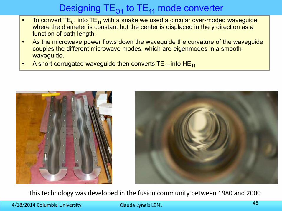
Designing TEO1 to TE11 mode converter
48
• To convert TE01 into TE11 with a snake we used a circular over-moded waveguide where the diameter is constant but the center is displaced in the y direction as a function of path length.
• As the microwave power flows down the waveguide the curvature of the waveguide couples the different microwave modes, which are eigenmodes in a smooth waveguide.
• A short corrugated waveguide then converts TE11 into HE11
This technology was developed in the fusion community between 1980 and 2000
Claude Lyneis LBNL4/18/2014 Columbia University
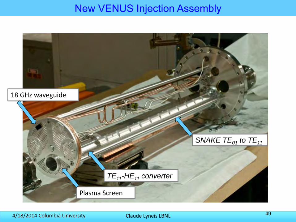
New VENUS Injection Assembly
49
SNAKE TE01 to TE11
TE11-HE11 converter
18 GHz waveguide
Plasma Screen
Claude Lyneis LBNL4/18/2014 Columbia University
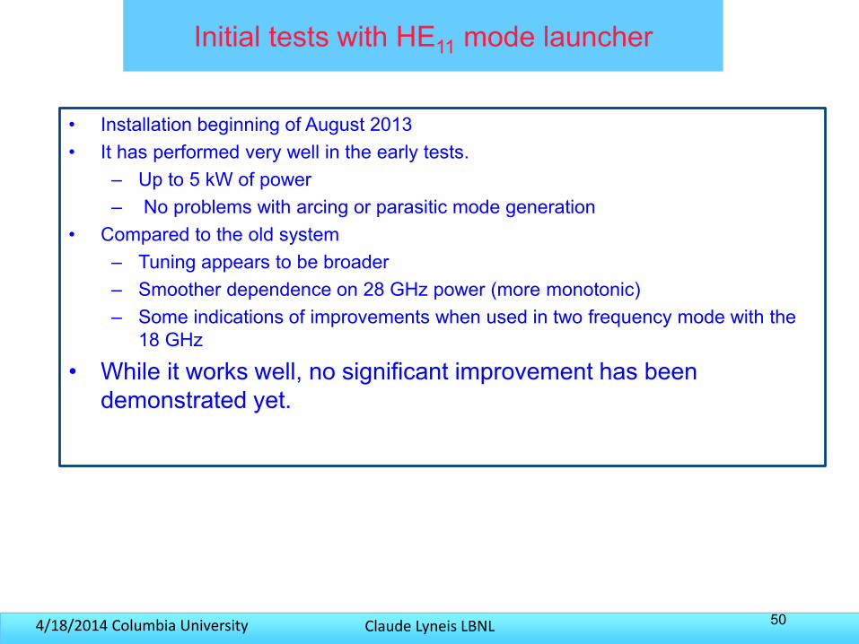
Initial tests with HE11 mode launcher
• Installation beginning of August 2013 • It has performed very well in the early tests.
– Up to 5 kW of power – No problems with arcing or parasitic mode generation
• Compared to the old system– Tuning appears to be broader– Smoother dependence on 28 GHz power (more monotonic)– Some indications of improvements when used in two frequency mode with the
18 GHz
• While it works well, no significant improvement has been demonstrated yet.
50
Claude Lyneis LBNL4/18/2014 Columbia University
Conclusion
• The performance of ECR Ion Sources has steadily improved over the last 40 years– Although from 2006 to present performance is relatively flat
• A detailed theoretical picture of the plasma physics is still open for improvement
• More plasma diagnostics for the hot electron parameters and for RF adsorption would be welcome
• Frequency scaling is roughly correct from 6 to 28 GHz and is expected to work for 4th generation ECR’s at ~50 GHz
• The technical challenges at 50 GHz make it attractive to look for new approaches
51