economical design of a single span long cylindrical … · for long shells, the schorer theory...
TRANSCRIPT

http://www.iaeme.com/IJCIET/index.asp 24 [email protected]
International Journal of Civil Engineering and Technology (IJCIET)
Volume 8, Issue 11, November 2017, pp. 24–34, Article ID: IJCIET_08_11_003
Available online at http://http://www.iaeme.com/ijciet/issues.asp?JType=IJCIET&VType=8&IType=11
ISSN Print: 0976-6308 and ISSN Online: 0976-6316
© IAEME Publication Scopus Indexed
ECONOMICAL DESIGN OF A SINGLE SPAN
LONG CYLINDRICAL SHELL ROOF WITH
EDGE BEAM USING THE SCHORER THEORY
Dr. B. H. V. Pai
Department of Civil Engineering, Manipal Institute of Technology
Manipal University, Manipal, Udupi, Karnataka, India
B. Durga Prasad Baliga
Department of Civil Engineering, Alva’s Institute of Engineering & Technology,
Moodabidri, Mangalore, Karnataka, India
ABSTRACT
Cylindrical shell roofs are common types of shells used for the structures, which
provide large free area without columns. In present work, a single span cylindrical
shell (arc of a circle as directrix) with edge beam has been analysed and designed.
The Schorer Theory which is extensively used for long shells has been used for the
analysis. A program in C language has been developed to analyze the shell and to give
the reinforcement details with edge beam and a solid diaphragm traverse. A simple
iterative technique is used to get the economical geometry of the shell structure.
Economical geometry of the shell with edge beam has been presented for one set of
span, radius of the shell and depth of the edge beam which is taken as constants. The
thickness, semi-central angle of the shell and width of the edge beam are treated as
variable.
Key words: Cylindrical shell, edge beam, C language code, stress resultants, varying
semi-central angle, varying edge beam width, shell efficiency, cost of construction.
Cite this Article: Dr. B. H. V. Pai and B. Durga Prasad Baliga, Economical Design of
a Single Span Long Cylindrical Shell Roof with Edge Beam using the Schorer Theory.
International Journal of Civil Engineering and Technology, 8(11), 2017, pp. 24–34.
http://www.iaeme.com/IJCIET/issues.asp?JType=IJCIET&VType=8&IType=11
1. INTRODUCTION
Owing to the large floor space uninterrupted by columns that it makes possible, and its
economy particularly when the shuttering is used repeatedly, the concrete thin shell roof has
been finding increasing use. Large roof spans of bus, railroad, and air terminals, sport stadia,
aerodrome hangars, textile mills, motor assembly plants and storage buildings have been
effectively covered with reinforced concrete shells. The problem of covering large floor
spaces using a few supporting members as possible is one which has drawn the attention of
engineers for centuries and varying solutions to this problem have produced some of world’s

Dr. B. H. V. Pai and B. Durga Prasad Baliga
http://www.iaeme.com/IJCIET/index.asp 25 [email protected]
most interesting buildings in the ancient as well as the modern age. One of the major
difficulties connected with large span construction arises from the self-weight of the material
employed, and possibilities of even reinforced concrete in its normal form are limited from
this point of view. The development of various forms of thin concrete shells capable of
transmitting direct loads in more than one direction simultaneously has, however, resulted in a
wider and more economical use of reinforced concrete in large span construction because of
the considerable saving in dead weight. The criterion for the transmission of loads in this
manner is the maintenance of the required shape of the shell. This is achieved by tying the
shell and the edge beams together at intervals by means of transverse stiffeners; with the
addition of suitable reinforcement, the shell can then not only sustain loads across the width
of its surface but also along its length. Thus, in the case of a single shell curved in one
direction in the form of a barrel vault, the shell acts as a beam along the length of the barrel
and forms in itself a completely self-contained structural element. Cylindrical shell forms can
be easily shored and easily reinforced. With such outstanding advantages engineers are not
generally familiar with shell structures because the theory and design of shell structures
involve complex mathematics. Figure 1. shows the classification of Singly Curved
Developable Shells[1].
Figure 1 Classification of shells as per IS: 2210 – 1988 [1]
2. STRUCTURAL ACTION OF THE SHELL
A shell structure, because of their geometry and small flexural rigidity of the skin, tend to
carry external loads by in plane forces in addition the transverse forces and moments. But in
its flatter counterparts, under similar loading conditions, develop only transverse force and
moments. By suitably selecting the shape of the shell, it is not only possible to reduce, but
also to eliminate completely the bending effects throughout the shell structure under the given
system of loading for flexure. The conditions of such shells can be termed as moment less
whose efficiency is obviously much more than the corresponding flat shapes. A shell structure
makes use of both the extensional and flexural rigidities in resisting the external loads. The
ratio of load to be carried to the quantity of material consumed in the case of the shell is very
high. Thus the structural efficiency of the shell structure largely depends on the presence of
the curvatures. As always the designer must have physical idea of the behaviour of the
structure he designs, in order to have a qualitative idea of the stresses in long shells with edge
beam it would not be working to imagine the combination as a huge beam with a curved

Economical Design of a Single Span Long Cylindrical Shell Roof with Edge Beam using the
Schorer Theory
http://www.iaeme.com/IJCIET/index.asp 26 [email protected]
cross-section. When simply supported at two curved ends by end frames, at mid span,
maximum tension is created in the edge beams and maximum compression at the crown of the
shell. Maximum shear force is near the supports and is taken by the edge beams and the lower
portions of the shell [2].
3. EFFICIENCY OF THE SHELL
From the above description of the stress distribution, we see that the major part of the shell is
subjected to compression. Within the limits of elastic stability concrete is excellently suited to
take compression and this is in fact the most efficient way in which it can be used. This is a
prime factor leading to the great economy of shell structures in reinforced concrete. The
reduced weight of the shell roof leads to further economy in the supporting frames and
foundations [3].
4. ECONOMIC ADVANTAGES OF THE SHELL
Low initial cost: This is mainly due to the structural efficiency of the shells. When a
number of repetitions are involved the method of centring also gives great scope of
economy.
Negligible maintenance cost.
Economy of steel: Besides reducing the cost, the economy of steel becomes an added
advantage in itself because of the storage of steel and the difficulty in procuring it. [3]
5. FUNCTIONAL ADVANTAGES OF THE SHELL [3]
Efficient use of floor space of larger spans and fewer columns.
The curvature of the shells and the unobstructed space underneath provides greater air
space and better ventilation.
The clear and smooth soffits of the shell gives much better appearance and provide an
excellent reflecting surface for light, giving sufficient and even illumination.
The clear lines in the interior have both psychological and hygienic advantages.
The elegance of the curve offers a new field of creation to the architect.
As the dead weight of the shell is small, large units of formwork are made in one piece
(without being too heavy) and are bodily moved from bay to bay on rails, thus
eliminating, dismantling and re-creating every time. This results in rapid construction.
6. CONSTRUCTION ASPECTS
Shell structures though not really difficult to construct, do demand special attention on the
part of both the designer and the construction engineer, for their successful completion. A
careful and coordinated control is necessary for the time and sequence of stripping the
supports of various members. In particular, it must be noticed that the supports for the edge
beams should not be removed till at least one adjacent shell is cast and cured sufficiently.
Edge beams and shells act in union and the former may not be strong even to take their own
loads by themselves.
Generally, a nominal mix of 1:2:4 (by nominal volume) may be used for the shells of
medium size and a nominal mix by volume of 1:1.5:3 for very large shells. In no case shall
the nominal mix for concrete used in shell construction is lower than 1:2:4. Rapid hardening

Dr. B. H. V. Pai and B. Durga Prasad Baliga
http://www.iaeme.com/IJCIET/index.asp 27 [email protected]
cement may also be used. The reinforcement in the shell must be carefully positioned with
respect to the thickness of the shell as the thickness is very small.
After a shell is designed, the most decisive factor that will govern the cost is the method
of centring. The curvature of the shell increases the cost of making the centring. This is offset
by repeating the centring a great number of times. The cost of erecting, stripping and moving
the centring can be effectively controlled by varying the size of the unit of centring. The
larger the units are used, the more elaborate will be the arrangements required for their lifting,
lowering and transporting from bay to bay. The construction engineer will do well to make a
special study of the problem in each individual case and determine the most economical unit
of centring and the arrangements for its handling [4].
7. PRINCIPLE OBJECTIVE
Structural engineers and architects have utilised computers for a long time keeping in mind
the end goal to fill in as a solid instrument in performing complicated investigation, outline
and drafting errands. Lamentably, the utilisation of computers has additionally been
extraordinarily restricted to routine undertakings. The emphasis must be moved in
empowering structural engineers for better comprehension of the design issue for which the
computers are being utilised. Hence an attempt is made to develop a C language code for the
economical design of a single span cylindrical shell roof with edge beam using The Schorer
Theory.
8. METHOD OF ANALYSIS
Based on the linear elastic theory, shells may be analysed using Elementary Method and
Analytical Methods. Beam Theory and Membrane Theory are the two elementary methods
which serve as a ready means of checking the suitability of the dimensions and are used as
preliminary tools for analysis. These are approximate methods and the stresses obtained are
greater than those obtained from analytical methods.
Analytical Methods comprises of Membrane Analysis and Edge Disturbance Analysis. In
membrane analysis, the shell is regarded as a perfectly flexible membrane, which is infinite in
extent and is assumed to carry loads by means of forces in its plane only. This analysis gives
true normal stresses in longitudinal and transverse direction along with the shear stresses.
Edge disturbances originate from the boundaries, altering the membrane state and causing
bending stresses in the shell. These are accounted for by carrying out edge disturbance
analysis. The superposition of the membrane and the edge disturbance stresses gives the final
stresses in the shell. The actual load is the sum of dead and imposed load. Imposed load on
various types of roofs are given in IS: 875 – 1987 (Part 2) [7].
Cylindrical shells with L/R ratio less than k will be analyzed using any of the accepted
analytical methods listed in IS: 2210 – 1988 [1]. For long shells, The Schorer Theory which is
derived from the Finsterwalder characteristic equation, by ignoring all the lower derivatives
with respect to φ in comparison with the eighth order derivative is widely used analytical
method. The Schorer Theory This theory is applicable only to shells with L/R≤∏.
9. METHOD OF DESIGN
The design part includes the design of shell, edge beam and end traverses. The design is done
in accordance with the recommendations given in IS: 2210 – 1988 [1].
In the design of shell, maximum tensile force is considered for the design of longitudinal
reinforcement. Since the transverse moment is the maximum at mid-span, the transverse

Economical Design of a Single Span Long Cylindrical Shell Roof with Edge Beam using the
Schorer Theory
http://www.iaeme.com/IJCIET/index.asp 28 [email protected]
reinforcement is computed for maximum moment at mid-span. The diagonal reinforcement in
the shell is designed to resist the principal tensions caused by the combined effects of Nx, Nφ,
and Nxφ. For simply supported cylindrical shell, at the support, both Nx and Nφ would be
zero and only Nxφ exists. Hence the principal forces at the support will be equal to +Nxφ and
the direction of this principal force will be 45°. Longitudinal steel is obtained by dividing the
maximum principal tension by the permissible stress in steel. For compressive forces caused
by Nx, nominal reinforcement will be provided. The design for Nφ and Mφ is carried out in
the same way as for a reinforced concrete section subjected to axial load and bending
moment. The transverse steel will be laid touching, and above or below, the longitudinal steel
which is arranged along the middle surface of the shell, depending upon whether the bending
moment at the section is hogging or sagging.
In the edge beam of a long shell, the neutral axis line is close to the junction between the
shell and the edge member so that the bulk of the longitudinal tensile force caused by Nx is
concentrated in the later. Because the stress in the steel is proportional to its distance from the
neutral axis, it is economical to arrange all the steel at the bottom of the edge beam. Nominal
reinforcement will be provided elsewhere in the edge member.
Traverses are provided to maintain the shape of the shell and to carry, in addition to its
own weight, reaction transferred from the shell in the form of shear forces and the loads
directly acting in them. A solid diaphragm is designed for tension at the springing, bending
moment due to dead weight and the shell forces; and shear due to the dead weight and shell
forces [5].
The shear force Nxφ transferred on the traverse from the shell shall be resolved into its
vertical and horizontal component. Area of steel is obtained by dividing the safe permissible
tensile stress in steel. The spacing will be provided as per IS: 2210 – 1988 [1] and IS: 456 –
2000 [6].
Steel for bending moment due to shell forces and due to the dead weight is carried out in
the same manner as that for any reinforce concrete section subjected to bending. Shear due to
shells and dead load of traverse is considered for design of a traverse in shear. In addition to
the shear reinforcement, haunching is provided to the traverse to accommodate the shear rush-
up at the junction of the springing of the shell and the edge beam [5].
10. C LANGUAGE CODE
A computer program in C language has been developed for the economical design of a single
span cylindrical shell, with arc of a circle as the directrix, and with edge beam. This program
gives the optimum geometry of the shell and edge beam for given data such as span of the
shell, chord width of the shell and depth of the edge beam. Live load, grade of concrete and
grade of steel can be given as input values. Prevailing rates for steel per kg, concrete per bag
and formwork per square area can be fed into the program. This program gives the stress
resultants and the reinforcement details for the shell, edge beam and the traverse. The
program also gives the weight of steel, volume of concrete and the area of form-work required
for the shell. Simple iterative technique has been used to obtain the economical shell
geometry by comparison of cost of construction, satisfying all requisite checks as per IS: 456
– 2000 [6] and IS: 2210 – 1988 [1]. Various standard problems were used for the verification
of the stress resultants.

Dr. B. H. V. Pai and B. Durga Prasad Baliga
http://www.iaeme.com/IJCIET/index.asp 29 [email protected]
11. NUMERICAL EXAMPLE
In the present work, an attempt is made to obtain an economical geometry of a single span
cylindrical shell with edge beam for span of the shell = 30 m, chord width = 9 m and depth of
the edge beam = 1.25 m. Live load = 0.65 kN/mm2. Semi-central angle is varied from 30 to 40
degrees.
Figure 2 Variation of Cost for varying Semi-central angle & Edge Beam Width
Figure 3 Variation of Cost for varying Semi-central angle & Edge Beam Width

Economical Design of a Single Span Long Cylindrical Shell Roof with Edge Beam using the
Schorer Theory
http://www.iaeme.com/IJCIET/index.asp 30 [email protected]
Figure 4 Variation of Cost for varying Semi-central angle & Edge Beam Width
Figure 5 Variation of Cost for varying Semi-central angle & Edge Beam Width
Figure 6 Variation of Cost for varying Semi-central angle & Edge Beam Width
Dr. B. H. V. Pai and B. Durga Prasad Baliga
http://www.iaeme.com/IJCIET/index.asp 31 [email protected]
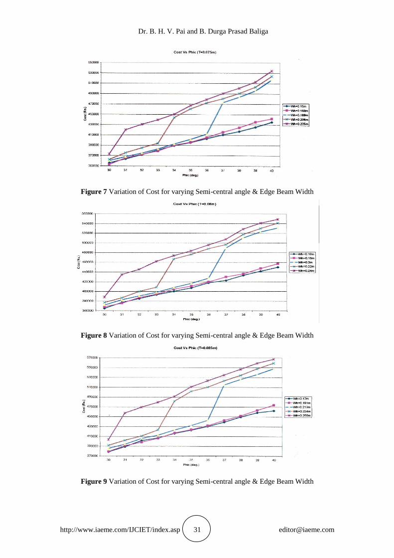
Figure 7 Variation of Cost for varying Semi-central angle & Edge Beam Width
Figure 8 Variation of Cost for varying Semi-central angle & Edge Beam Width
Figure 9 Variation of Cost for varying Semi-central angle & Edge Beam Width

Economical Design of a Single Span Long Cylindrical Shell Roof with Edge Beam using the
Schorer Theory
http://www.iaeme.com/IJCIET/index.asp 32 [email protected]
Figure 10 Variation of Cost for varying Semi-central angle & Edge Beam Width
Figure 11 Variation of Cost for varying Semi-central angle & Edge Beam Width
Figure 12 Variation of Cost for varying Semi-central angle & Edge Beam Width

Dr. B. H. V. Pai and B. Durga Prasad Baliga
http://www.iaeme.com/IJCIET/index.asp 33 [email protected]
12. RESULTS AND DISCUSSIONS
Variations of cost of construction of shell at every one degree increment in semi-central angle
are presented from Fig. 2 to Fig. 12. From the cost comparison study, for every one degree
increase in semi-central angle the following observations are made.
Cost of construction of shell increases almost linearly for every 0.001 m and 0.01 m
increase in width of edge beam, for every 0.005 m increase in shell thickness.
For every 0.013 m increase in width of the edge beam and increment of 0.005 m shell
thickness, the graphs show the cost of construction of shell increases almost linearly
for all values of semi-central angle within 36 degrees, and then suddenly shoots up for
semi-central angle between 36 to 37 degrees, and later on achieves almost linear
increase in cost.
For every 0.014 m increase in width of the edge beam and increment of 0.005 m shell
thickness, the graphs show the cost of construction of shell increases almost linearly
for all values of semi-central angle between 33 to 34 degrees, and then achieve almost
linear increase in cost.
For every 0.015 m increase in width of the edge beam and increment of 0.005 m shell
thickness, the graphs show the cost of construction of shell initially increases rapidly
for all values of semi-central angle between 0 to 31 degrees, and then achieve almost
linear increase in cost.
Economical geometry and cost of construction of shell with edge beam and traverse
obtained through C program for the numerical example considered is presented below:
Span = 30 m, Chord Width = 9 m, Shell Thickness = 0.05 m, Semi-central angle =
30°, Shell Radius = 9 m, Rise of the Shell = 1.206 m, Depth of the Edge Beam = 1.250
m, Width of the Edge Beam = 0.113 m, Total Cost of Construction = Rs. 5, 78,
904.00.
13. CONCLUSIONS
With the above discussions, it can be concluded that:
There is 4.6 % to 6.3 % increase in longitudinal stresses and 9.3 % to 12.3 % increase
in shear stresses for semi-central angle between 36 to 37 degrees.
There is 4.2 % to 5.6 % increase in longitudinal stresses and 8.7 % to 11.4 % increase
in shear stresses for semi-central angle between 33 to 34 degrees.
There is 3.9 % to 4.75 % increase in longitudinal stresses and 7.6 % to 9.8 % increase
in shear stresses for semi-central angle between 33 to 34 degrees.
For the given data and from the above results, it is observed that economical geometry
of the shell structures is when radius of the shell is equal to the chord width of the
shell.
Overall, it can be concluded that the cost of construction of the shell decreases as the
semi-central angel and width of the edge beam decreases.
The cost variation diagram can be readily generated for various input data and can be
used as ready reference by practicing engineers.

Economical Design of a Single Span Long Cylindrical Shell Roof with Edge Beam using the
Schorer Theory
http://www.iaeme.com/IJCIET/index.asp 34 [email protected]
REFERENCES
[1] IS: 2210-1988, “Criteria for the Design of Reinforced Concrete Shell Structures and
Folded Plates, Bureau of Indian Standards, New Delhi.
[2] Ramaswamy, G. S., “Design and Construction of Concrete Shell Roofs”, C.B.S Publishers
& Distributors, New Delhi, 1986.
[3] nptel.ac.in/courses/105106144/word/topic/eBk%20-%20TPC%2016_F.pdf
[4] IS: 2204-1962, Reaffirmed 2000, “Code of Practice for Construction of Reinforced
Concrete Shell Roofs”, Bureau of Indian Standards, New Delhi.
[5] Gibson, J. E., “The Design of Cylindrical Shell Roofs”, E & F. N. Span Ltd., London,
1961.
[6] IS: 456-2000, “Code of Practice for Plain and Reinforced Concrete”, Bureau of Indian
Standards, New Delhi.
[7] IS: 875 (Part 2)-1987, “Code of Practice for Design Loads (other than earthquake) for
Building and Structures (Part 2-Imposed Loads)”, Bureau of Indian Standards, New Delhi.
[8] M V Babu Tanneru, Lakshmipathi Yerra, K Vijaya Krishna Varma Analysis of Ring
Stiffened Cylindrical Shells Using Functionally Graded Material. International Journal of
Mechanical Engineering and Technology (IJMET) 8(7), 2017, pp.145–156.
[9] K. Vijaya Krishna Varma and V.S.V Sai Sumanth, Structural And Thermal Analysis Of
Reinforced Nozzle-Cylindrical Shell Intersection Under Internal Pressure And Nozzle
Radial Thermal Expansion, International Journal of Mechanical Engineering and
Technology 8(8), 2017, pp. 249–255.