ece 370 introduction to biomedical engineering bioinstrumentation - bioelectronics ·...
TRANSCRIPT

University of Cyprus
Biomedical Imaging and Applied Optics
ECE 370
Introduction to Biomedical Engineering
Bioinstrumentation - Bioelectronics

2 2
Biomedical Instrumentation
• Diagnosis and therapy depend heavily on the use of medical instrumentation.
• Medical procedures:
• Medicine can be defined as a multistep procedure on an individual by a physician or group of physicians repeated until the symptoms disappear
• Medical Procedure
1. Collection of data - qualitative and/or quantitative
2. Analysis of data
3. Decision making
4. Treatment planning based on the decision
• Medical devices play a critical role in all of the above steps
• Diagnostic, Therapeutic, Monitoring devices
3 3
Biomedical Instrumentation
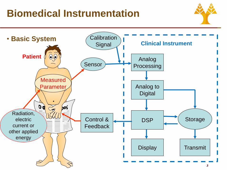
• Basic System
Patient
Sensor Analog
Processing
Analog to
Digital
Storage DSP
Display Transmit
Control &
Feedback
Clinical Instrument
Measured
Parameter
Radiation,
electric
current or
other applied
energy
Calibration
Signal

4 4
Biomedical Instrumentation
• Components of Biomedical Instrumentation System…
• A sensor • Detects biochemical, bioelectrical, or biophysical parameters
• Provides a safe interface with biological materials
• Converts a physical parameter to an electrical output • Should respond only to the form of energy present in the
parameter
• Should be minimally invasive (ideally noninvasive)
• Electronics • Signal conditioning
• Amplify, filter, match the impedance of the sensor
• Further analog processing
• Convert analog signal to digital
• The electronics interface must • Match the electrical characteristics of the sensor/actuator with
computation unit
• Preserve the signal to noise ratio of sensor
• Preserve the bandwidth (i.e., time response) of sensor/actuator
• Provides a safe interface with the sensor/actuator
• Provides a safe interface with the computation unit
• An actuator • Delivers external agents via direct or indirect contact
• Controls biochemical, bioelectrical, or biophysical parameters
• Provides a safe interface with biologic materials

5 5
Biomedical Instrumentation
Components of Biomedical Instrumentation System…
• The computation unit
• provides primary user interface
• provides primary control for the overall system
• provides data storage for the system
• provides primary signal processing functions for the system
• maintains safe operation of the overall system
• Output (display or printer)
• Results must be displayed in a form that the human operator
can perceive
• Numerical, Graphical, Discrete or continuous, Permanent or
temporary, Visual or acoustical
• Auxiliary elements
• Data storage
• Data transmission
• Control and feedback
• Calibration signal

6 6
Biomedical Instrumentation
• Measured Parameters
• Physical quantity, property,
or condition that the
system measures
• Biopotential
• Pressure
• Flow
• Dimension (imaging)
• Displacement (velocity,
acceleration, and force)
• Impedance
• Temperature
• Chemical concentrations
Μαγνητική Τομογραφία
Αξονική Τομογραφία
Υπέρηχοι
Εγκεφαλογράφημα
Καρδιογράφημα
Μυογράφημα
Ανάλυση και Επεξεργασία
Διάγνωση

7 7
Biomedical Instrumentation
• Measured Parameters
Measurement Range Frequency, Hz Method
Blood flow 1 to 300 mL/s 0 to 20 Electromagnetic or ultrasonic
Blood pressure 0 to 400 mmHg 0 to 50 Cuff or strain gage
Cardiac output 4 to 25 L/min 0 to 20 Fick, dye dilution
Electrocardiography 0.5 to 4 mV 0.05 to 150 Skin electrodes
Electroencephalography 5 to 300 V 0.5 to 150 Scalp electrodes
Electromyography 0.1 to 5 mV 0 to 10000 Needle electrodes
Electroretinography 0 to 900 V 0 to 50 Contact lens electrodes
pH 3 to 13 pH units 0 to 1 pH electrode
pCO2 40 to 100 mmHg 0 to 2 pCO2 electrode
pO2 30 to 100 mmHg 0 to 2 pO2 electrode
Pneumotachography 0 to 600 L/min 0 to 40 Pneumotachometer
Respiratory rate 2 to 50 breaths/min 0.1 to 10 Impedance
Temperature 32 to 40 °C 0 to 0.1 Thermistor

8 8
Biomedical Instrumentation
• Bioinstrumentation should be designed with a specific signal in mind.
• The values of the specifications • Have been agreed upon by committees
• Are drawn from research, hospitals, industry, and government.
Specification Value
Input signal dynamic range ±5 mV
Dc offset voltage ±300 mV
Slew rate 320 mV/s
Frequency response 0.05 to 150 Hz
Input impedance at 10 Hz 2.5 M
Dc lead current 0.1 A
Return time after lead switch 1 s
Overload voltage without damage 5000 V
Risk current at 120 V 10 A
Specifications for an electrocardiograph

9 9
Biomedical Instrumentation
• Biomedical measurement systems should demonstrate high …
• Resolution • The smallest incremental quantity that can be
reliably measured.
• However, high resolution does not imply high accuracy.
• Precision • Obtaining the same value from repeated
measurements from the same input under the same conditions.
• However, high precision does not imply high accuracy
• Accuracy • Obtaining the true value from repeated
measurements from the same input under the same conditions
• Repeatability • The quality of obtaining the same output from
repeated measurements from the same input over a period of time.
Low precision High precision
Low accuracy High accuracy
Low Resolution High Resolution
10 10
Biomedical Instrumentation
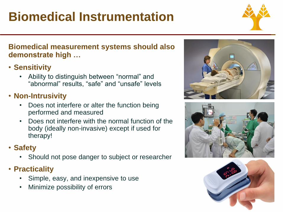
Biomedical measurement systems should also demonstrate high …
• Sensitivity
• Ability to distinguish between “normal” and “abnormal” results, “safe” and “unsafe” levels
• Non-Intrusivity
• Does not interfere or alter the function being performed and measured
• Does not interfere with the normal function of the body (ideally non-invasive) except if used for therapy!
• Safety
• Should not pose danger to subject or researcher
• Practicality
• Simple, easy, and inexpensive to use
• Minimize possibility of errors

11 11
Biomedical Instrumentation
• Problems encountered in measuring a living system
• Many crucial variables in living systems are inaccessible and can not be directly measured
• Variables measured are seldom deterministic
• Intra-patient and Inter-patient variability
• Some biomedical measurements depend on the energy of an external stimulus
• Operation of instruments in the medical environment imposes important additional constraints

12 12
Biomedical Instrumentation
• Errors in measurements • When we measure a variable, we seek to determine the true value
• This true value may be corrupted by a variety of errors.
• For example • Electric and magnetic fields from the power lines may couple into the wires and cause
an undesired added voltage called interference
• Movement of electrodes on the skin may cause an undesired added voltage called an artifact.
• Electronic noise • Thermal voltages in the amplifier semiconductor junctions may cause undesired added
random voltage changes
• Drift • Temperature changes in the amplifier electronic components may cause undesired slow
changes in voltage
• Digitization errors • Measurements become discrete (steps) in both time and amplitude
• We must evaluate each of these error sources to determine their size and what we can do to minimize them
• e.g. frequency filters can be used to reduce noise and interference.

13 13
Biomedical Instrumentation
• Calibration • The instruments should be
calibrated against a standard • An accuracy 3 to 10 times better
than the desired calibration accuracy
• The accuracy of the standard should be traceable
• National Institute of Standards and Technology, TSI, etc.)
• Certification • The instruments should be certified
for safety • E.g. CE
• Regulatory Approval • The instruments must be tested in
clinical trials
• Their clinical use must be approved by the appropriate bodies
• E.g. FDA

14 14
Amplification Basics
• The term "amplify" basically means to make stronger.
• Types of amplification
• There are three kinds of amplifications: Two major types, and the third type is derived from the another two :
• Voltage Amplifier - an amp that boosts the voltage of an input signal
• Current Amplifier - an amp that boosts the current of a signal
• Power Amplifier - the combination of the above two amplifiers

15 15
Bioelectric Amplifier
• Bioelectric Amplifier
• Is the amplifier that used to process bio-potentials
• The gain may be
• Low gain amp: gain factor bw X1 and X10 (EX: action potential)
• Medium gain amp: gain factor bw X10 and X1000 (EX: ECG, Muscles potentials, …)
• High gain or low-level signal amp: gain factor over X10000 to as high as X1000000 (EX: EEG)
• It is usually ac coupled.
• DC-coupling is required where the input signal are clearly dc or change very slowly (0.05 Hz)
• Exceptional for EX.: ECG signal should be AC coupled despite of the component as low as 0.05 Hz to overcome electrode offset potential from electrode-skin connection
• The high-frequency response is the frequency at which the gain drops 3dB below its midfrequency value (for ECG form 0.05 to 100 Hz)

16 16
Bioelectric Amplifier
• Important parameters in a bioelectric amp:
• Noise: normally is the thermal noise generated in resistances and semiconductors devices.
• Drift: change in output signal voltage caused by change in operating temperature.
• High input impedance: 107 to 1012 Ω and it should be at least an order of magnitude high than the source impedance.
• Integrated circuit (IC) operational amplifier is well suited as bioelectric amp because of these properties.

17 17
Amplification Basics
• Types of Amplifiers
• Vacuum Valve
• Transistor
• Operational amplifier
• Vacuum Tube
• In electronics, a vacuum tube or (outside North America) thermionic valve or just valve, is a device generally used to amplify, switch or otherwise modify, a signal by controlling the movement of electrons in an evacuated space.
• Transistor
• Bipolar junction transistor (BJT) are two diodes joined with a very thin common region
• A small electrical input can be amplified by transistor
A simple one-
transistor
amplifier with
positive and
negative supplies

18 18
Operational Amplifier (Op-amp)
• The op-amp is a device for increasing the power of a signal.
• It does this by taking power from a power supply and controlling the output to match the input signal shape but with a larger amplitude (Amplification).
• The op-amp is used also to perform arithmetic operations (addition, subtraction, multiplication) with signals.
• The properties of the negative feedback loop determine the properties of the circuit containing an op-amp.
• It has two inputs: the inverting input (-) and the non-inverting input (+), and one output.
• It has usually two supplies (±Vss) but it can work with one.
Inverting
input
Non-inverting
input
+
- Output
+Vss
-Vss
Symbol of op-amplifier
19 19
Operational Amplifier (Op-amp)
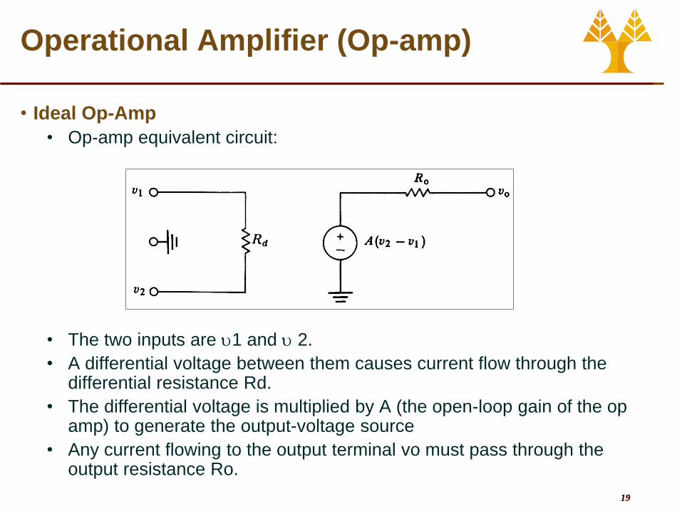
• Ideal Op-Amp
• Op-amp equivalent circuit:
• The two inputs are 1 and 2.
• A differential voltage between them causes current flow through the differential resistance Rd.
• The differential voltage is multiplied by A (the open-loop gain of the op amp) to generate the output-voltage source
• Any current flowing to the output terminal vo must pass through the output resistance Ro.

20 20
Operational Amplifier (Op-amp)
• Inside the Op-Amp (IC-chip)
20 transistors
11 resistors
1 capacitor

21 21
Operational Amplifier (Op-amp)
• Real vs. Ideal Op-amp
Parameter Ideal Op Amp Typical Op Amp
Open-loop voltage gain A ∞ 105 – 109
Common mode voltage gain 0 10-5
Frequency response f ∞ 1- 20 MHz
Input impedance Zin ∞ 106 Ω (bipolar)
109–1012 Ω (FET)
Output impedance Zout 0 100 – 1000 Ω

22 22
Operational Amplifier (Op-amp)
• Summing Point Constraint
• In a negative feedback system, the ideal op-amp output voltage
attains the value needed to force the differential input voltage and
input current to zero.
• Circuit solution
1. Verify that negative feedback is present.
2. Assume that the differential input voltage and the input current of
the op amp are forced to zero. (This is the summing-point
constraint.)
3. Apply standard circuit-analysis principles, such as Kirchhoff’s laws
and Ohm’s law, to solve for the quantities of interest.

23 23
Operational Amplifier (Op-amp)
• Applying the Summing Point Constraint

24 24
1
2
in R
R
v
vA o
v
Operational Amplifier (Op-amp)
• Inverting Amplifier • Non-inverting Amplifiers
1
2
in
1R
R
v
vA o
v

25 25
Operational Amplifier (Op-amp)
• Active Filters- Low-Pass Filter
• A low-pass filter attenuates high frequencies
ffi
f
i
o
CRjR
R
jV
jV
1
1 G Gain
|G|
freq fc = 1/2RiCf
Rf/Ri
0.707 Rf/Ri
+
Ri Rf
i o

26 26
Operational Amplifier (Op-amp)
• Active Filters (High-Pass Filter)
• A high-pass filter attenuates low frequencies and blocks dc.
Ci
+
Ri
i o
Rf
ii
ii
i
f
i
o
CRj
CRj
R
R
jV
jV
1 G Gain
|G|
freq fc = 1/2RiCf
Rf/Ri
0.707 Rf/Ri

27 27
Operational Amplifier (Op-amp)
• Active Filters (Band-Pass Filter)
• A bandpass filter attenuates both low and high frequencies.
iiff
if
i
o
CRjCRj
CRj
jV
jV
11
|G|
freq fcL = 1/2RiCi
Rf/Ri
0.707 Rf/Ri
fcH = 1/2RfCf
+
i o
Rf Ci Ri
Cf

28 28
Operational Amplifier (Op-amp)
• Differential Amplifier
• In differential mode you can signals common to both input signals
1V
3V
2V
1 2
2 1
1
f g
f
out
R R
R R
RV V V
R

29 29
Operational Amplifier (Op-amp)
• Instrumentation Amplifier • High gain and high-input impedance.
• Composed of 2 amplifiers in noninverting format and a 3rd amplifier as a differential amplifier
31
2 1 2
21out
gain
V RR
V V R R

30 30
Operational Amplifier (Op-amp)
• Additional considerations in a bioamplifier • Noise
• DC Drift (low frequency)
• Electronic noise (low and high frequency)
• Line interference (50 or 60 Hz)
• How to decrease noise artifacts? • Shielding of electrodes and equipment
• Filtering (Low pass, high pass)

31 31
Operational Amplifier (Op-amp)
• Additional considerations in a bioamplifier • Motion artifacts
• The contact between the electrode and the tissue changes during the relative motions between the electrodes and the tissue.
• How to decrease the motion artifacts? • High input resistance of the amplifier
• High quality electrodes
• Reduction of the source impedance by usage of electrode gel.
32 32
Operational Amplifier (Op-amp)
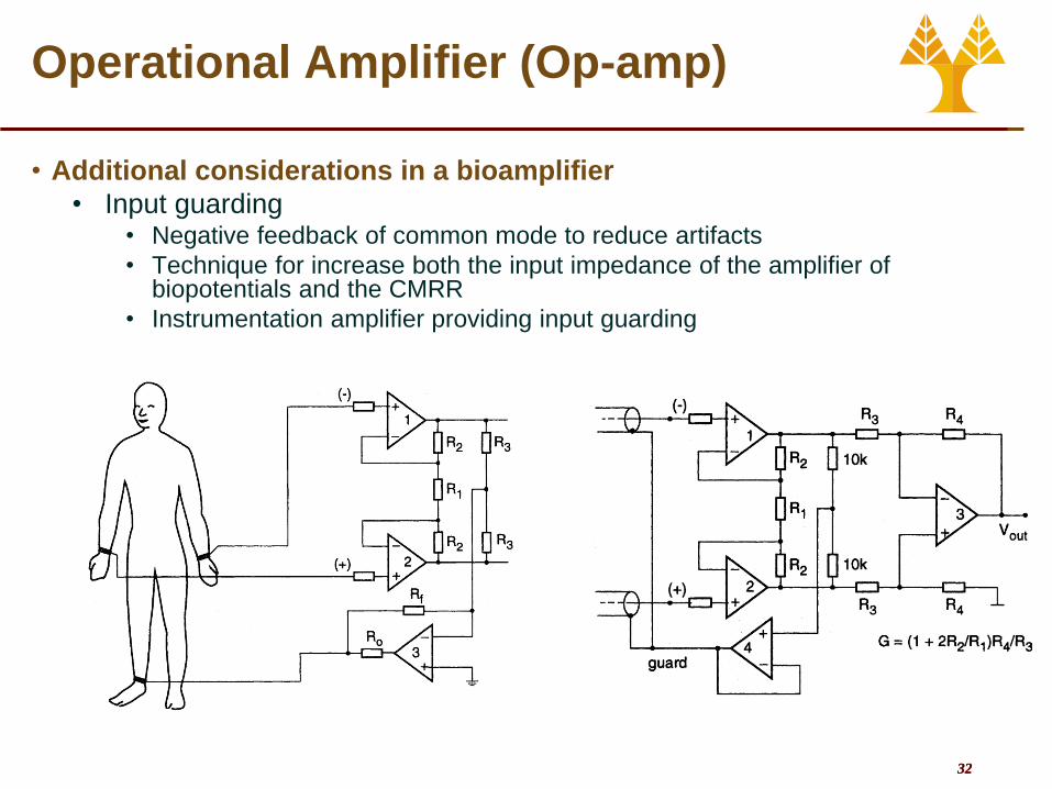
• Additional considerations in a bioamplifier
• Input guarding • Negative feedback of common mode to reduce artifacts
• Technique for increase both the input impedance of the amplifier of biopotentials and the CMRR
• Instrumentation amplifier providing input guarding

33 33
Operational Amplifier (Op-amp)
• Additional considerations in a bioamplifier
• Isolation amplifier
• Isolation is realized in the following technologies:
• Transformer isolation
• Opto-isolation.
• Complete galvanic separation between the input
stage (patient) and the remaining part of the
measure equipment.
Galvanic decoupling
of the patient

34 34
•Diodes
•Zener diodes
•Gas-discharge tubes
Operational Amplifier (Op-amp)
• Additional considerations in a bioamplifier • Surge protection of the bioamplifiers
• Protection of the amplifier from damage due to surge input potentials.
• Zener diodes and gas discharge tubes switch to conducting (short circuit) mode at high voltages (above the “breakdown” voltage

35 35
Operational Amplifier (Op-amp)
• ECG Monitor Circuit

36 36
Operational Amplifier (Op-amp)
• ECG Monitor Circuit

37 37
Other (nonelectric) Biosignals
• Measuring skin resistance
• Galvanic Skin response
(GSR)
• Electrodermal Activity (EDA)
• Skin Conductance Level
(SCL)
• Measuring peripheral body
temperature
• Thermistors present a
resistance that changes with
temperature

38 38
Other (nonelectric) Biosignals
• Measuring blood pressure
• Inflate a cuff to momentarily
interrupt the circulation
• Measure the pressure at
which pulsation appears again
• Measuring blood
oxygenation
• Measure Red/Infrared Ratio
• Digital Signal Processing is
used to do the “math”

39 39
Other (nonelectric) Biosignals
• Measuring blood glucose
• Oxidase glucose on the strip
• Measure the change (color,
conductance, etc)
• Measuring breathing
capacity
• Flow, temperature, motion

40 40
Other (nonelectric) Biosignals
• And just about everything else

University of Cyprus
Biomedical Imaging and Applied Optics
Appendix
DC Circuits
Capacitors and Inductors
AC Circuits
Operational Amplifiers

42 42
Circuit Elements
An electrical circuit consists of circuit elements such as voltage sources,
resistances, inductances and capacitances that are connected in closed
paths by conductors

43 43
DC Circuits
• Current:
• The rate of motion of charge in a circuit
• Symbol: I (or sometimes i).
• SI units: C/s = ampere (A)
• “Conventional current”
• Assumed to consist of the motion of positive charges.
• Conventional current flows from higher to lower potential.
• AC/DC
• Direct current (DC) flows in one direction around the circuit
• Alternating current (AC) “sloshes” back and forth (time-varying that changes its sign periodically)
q q dqI
t t dt

44 44
DC Circuits
• Ohm’s Law and Resistance:
• The current that flows through an
object is directly proportional to the
voltage applied across the object
• The constant of proportionality, R, is
called the resistance of the object.
• SI unit of resistance: ohm (Ω)
• Resistance depends on the
geometry of the object, and a
property, resistivity, of the material
from which it is made
• Resistivity symbol: ρ
• SI units of resistivity: ohm m (Ω m)
IRV
A
LR
L
cross-sectional area A

45 45
DC Circuits
• Electrical Power
• Power is the time rate of doing work
• Voltage is the work done per unit charge
• Current is the time rate at which charge goes by
• Combining
• Ohm’s Law substitutions allow us to write several equivalent expressions for power
• Regardless of how specified, power always has SI units of watts (W)
R
VRIVIP
22
VIt
q
q
W
t
WP
t
qI
q
WV
t
WP

46 46
DC Circuits
• Series Connection
• A circuit, or a set of circuit elements, are said to be connected “in series” if there is only one electrical path through them.
• The same current flows through all series-connected elements. (Equation of continuity)
• Parallel Connection
• A circuit, or a set of circuit elements, are said to be connected “in parallel” if the circuit current is divided among them.
• The same potential difference exists across all parallel-connected elements.
1 2
1 1 1 1...
eq nR R R R
1 2 ...eq nR R R R

47 47
DC Circuits
Kirchoff’s Laws
• The Voltage Law:
• Around any closed loop in a
circuit, the sum of the potential
changes must equal zero.
• (Energy conservation)
• The Current Law:
• At any point in a circuit, the
total of the currents flowing
into that point must be equal
to the total of the currents
flowing out of that point.
• (Charge conservation;
equation of continuity)

48 48
DC Circuits
• Node Voltage Analysis • Mesh Current Analysis
svv 1
03
32
4
2
2
12
R
vv
R
v
R
vv
03
23
5
3
1
13
R
vv
R
v
R
vv
From Kirchoff’s Current Law
1 3 2 1 2 3( ) ( ) 0Ai i R i i R v
From Kirchoff’s Voltage Law
1 2 3 2 4( ) 0Bi i R v i R
1 3 2 3 1( ) 0Bi i R i R v

49 49
DC Circuits
• Superposition Principle
• The superposition
principle states that the
total response is the
sum of the responses to
each of the
independent sources
acting individually

50 50
DC Circuits
• Thévenin Equivalent Circuits
oct vV oc
sc
t
vR
i
t eqR R
Circuit with its source zeroed

51 51
DC Circuits
• Norton Equivalent Circuits
scn iI t
n
t
VI
R

52 52
tLL
LL
Lt
tLLL
Lt
tL RR
dR
dPR
RR
VRiP
RR
VI
0
2
2
DC Circuits
• Maximum Power Transfer

53 53
DC Circuits
• Diode
• Semiconductor
device
• Positive and
negative polarities A forward-biased diode
circuit
A reverse-biased diode
circuit
A bipolar square wave applied to a forward-biased diode circuit
Semiconductor Diode Rectifier

54 54
Summary Table of DC Concepts

55 55
Capacitors and Inductors
• Capacitance
• Ability to store charge
• The SI unit of capacitance is
the farad:
• 1 farad = 1 F = 1
Coulomb/Volt
• For a given charge, a
capacitor with a larger
capacitance will have a
greater potential difference
0
0
0
AQ V C V
d
AC
d
k AC
d
(with dielectric)

56 56
Capacitors and Inductors
• Like resistors, capacitors in circuits can be connected in
series, in parallel, or in more-complex networks containing
both series and parallel connections.
1 2 ...eq nC C C C 1 2
1 1 1 1..
eq nC C C C

57 57
Capacitors and Inductors
• Inductance
• Ability to store magnetic
energy
• The polarity of the voltage is
such as to oppose the change
in current (Lenz’s law).
• Inductance, unit: henry [H]

58 58
Capacitors and Inductors
• Like resistors, inductors in circuits can be connected in
series, in parallel, or in more-complex networks containing
both series and parallel connections.
321
11
LLLLeq
321 LLLLeq

59 59
RC Circuits
• A capacitor connected in series with a resistor is part of an RC
circuit.
• Resistance limits charging current
• Capacitance determines ultimate charge
• Unlike a battery, a capacitor cannot provide a constant source of potential difference.
• This value is constantly changing as the charge leaves the plate.
• Current due to a discharging capacitor is finite and changes over time.

60 60
RC Circuits
• Charging the capacitor
• Assume no initial charge in the capacitor
• At the instant the source is connected,
the capacitor starts to charge.
• The capacitor continues to charge until it
reaches its maximum charge (Q = Cε)
• Once the capacitor is fully charged, the
current in the circuit is zero.
• The potential difference across the
capacitor matches that supplied by the
battery
• The charge on the capacitor increases
exponentially with time
• τ is the time constant
• τ = RC
0( ) 1 1
( )
t t
RC
t t
RCo
q t C e Q e
dq CeI t e I e
dt RC

61 61
RC Circuits
• Discharging the capacitor
• Assume a fully charged capacitor
• At the instant the switch closes, the
capacitor starts to charge.
• The capacitor continues to discharge
until it reaches 0
• Once the capacitor is fully discharged,
the current in the circuit is zero.
• The charge on the capacitor decreases
exponentially with time
• τ is the time constant
• τ = RC 0
0
( )
( )
t t
RC
t t
q t C e Q e
dQ CI t e I e
dt RC

62 62
AC Circuits
• Instantaneous voltage
• Instantaneous current
• θ is the phase angle
• In phasor form
• Impedance
• In series
• In parallel
22
L CZ R X X
v(t) = Vmax sin ωt
i(t) = Imax sin (ωt - θ) Imax= Vmax /|Z|
Zeq = (R1+R2)+j(X1+X2)
1/Zeq=1/(R1 +jX1)+1/(R2 +jX2)
Z =R+jX X=XL-Xc
θ =tan-1(X/R)
V=Vrms∟0 I = Irms∟θ Vrms=Vmax/√2 , Irms=Imax /√2
Z = V / I

63 63
Voltage and current waveforms in a resistive circuit
Voltage and current waveforms in a capacitive circuit
RR RIV
CCC Z IV
90111
CCjC
jZC
RZ R
AC Circuits

64 64
Voltage and current waveforms in an inductive circuit
Voltage and current waveforms in an RC series circuit
LL Lj IV
90 LLjZL
LLL Z IV
AC Circuits

65 65
AC Circuits
• Power can be expressed
in rectangle form
• P- real power
• Q–reactive power
• Power factor
• Maximum Power Transfer
S = P + jQ
P=VrmsIrmscos(θ) =I2rmsR
Q = VrmsIrmssin(θ) = V2rms/X
S2 = P2 + Q2
PF = cos(θ) = cos(θv-θi)
cos(θ)=1 θ = 0
Zload = Zt*

66 66
Summary Table of AC Concepts

67 67
Operational Amplifier (Op-amp)
• The op-amp is a device for increasing the power of a signal.
• It does this by taking power from a power supply and controlling the output to match the input signal shape but with a larger amplitude (Amplification).
• The op-amp is used also to perform arithmetic operations (addition, subtraction, multiplication) with signals.
• The properties of the negative feedback loop determine the properties of the circuit containing an op-amp.
• It has two inputs: the inverting input (-) and the non-inverting input (+), and one output.
• It has usually two supplies (±Vss) but it can work with one.
Inverting
input
Non-inverting
input
+
-
Output
+Vs
s
-
Vs
s
Symbol of op-amplifier

68 68
Operational Amplifier (Op-amp)
• Ideal Op-Amp
• Op-amp equivalent circuit:
• The two inputs are 1 and 2.
• A differential voltage between them causes current flow through the differential resistance Rd.
• The differential voltage is multiplied by A (the open-loop gain of the op amp) to generate the output-voltage source
• Any current flowing to the output terminal vo must pass through the output resistance Ro.
69 69
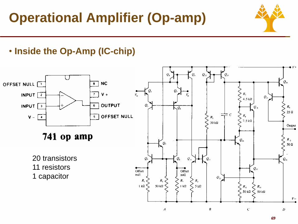
Operational Amplifier (Op-amp)
• Inside the Op-Amp (IC-chip)
20 transistors
11 resistors
1 capacitor

70 70
Operational Amplifier (Op-amp)
• Real vs. Ideal Op-amp
Parameter Ideal Op Amp Typical Op Amp
Open-loop voltage gain A ∞ 105 – 109
Common mode voltage gain 0 10-5
Frequency response f ∞ 1- 20 MHz
Input impedance Zin ∞ 106 Ω (bipolar)
109–1012 Ω (FET)
Output impedance Zout 0 100 – 1000 Ω

71 71
Operational Amplifier (Op-amp)
• Summing Point Constraint
• In a negative feedback system, the ideal op-amp output voltage
attains the value needed to force the differential input voltage and
input current to zero.
• Circuit solution
1. Verify that negative feedback is present.
2. Assume that the differential input voltage and the input current of
the op amp are forced to zero. (This is the summing-point
constraint.)
3. Apply standard circuit-analysis principles, such as Kirchhoff’s laws
and Ohm’s law, to solve for the quantities of interest.

72 72
Operational Amplifier (Op-amp)
• Applying the Summing Point Constraint

73 73
1
2
in R
R
v
vA o
v
Operational Amplifier (Op-amp)
• Inverting Amplifier • Non-inverting Amplifiers
1
2
in
1R
R
v
vA o
v

74 74
Operational Amplifier (Op-amp)
• Voltage Follower
10
111
2
R
R
v
vA o
vin

75 75
Operational Amplifier (Op-amp)
• Summing Amplifier

76 76
dt
dvRCtvo
in
Operational Amplifier (Op-amp)
• Differentiators • Integrators
dttvRC
tv
t
o in
0
1