earthwork and mass diagrams
TRANSCRIPT

NDDOT Construction Conference 2011 East Conference: March 2 and 3, 2011 West Conference: March 7 and 8, 2011

Earthwork Mass Diagrams How a Mass Diagram is Used Note: All information is taken from the NDDOT Standard Specifications for Road and Bridge Construction and the Construction Manual unless
otherwise noted.

Earthwork

Earthwork Topics Cross Sections Quantities- Excavation and Embankment
using average end area method Total Quantities- Topsoil Shrinkage

Cross Sections Two Types 1. Existing 2. Proposed Cross sections tell us the amount of cut and
fill at each station.

Quantities Excavation- the amount of material that
needs to be removed from the grade. Embankment- the amount of material that
needs to be added to the grade. Excavation and embankment are calculated
with cross sections using the average end area method.

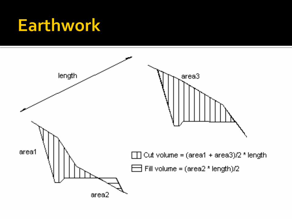
Average End Area Method The area between the existing ground and
proposed ground is calculated at each cross-section.
The area between two consecutive cross-sections is averaged.
This area is multiplied by the distance between two cross-sections.

Total Quantities Topsoil- topsoil quantities are not calculated
into the excavation or embankment. This is a separate value that has to be dealt with separately.
Imported topsoil is needed if the stripping volume acquired does not fulfill the quantity of topsoil that is proposed.
Shrinkage Shrinkage is the % additional volume added
to the embankment quantity. Three States of Material 1. Bank 2. Loose 3. Compacted


Shrinkage In NDDOT plan sets, it will state that “XX%
additional volume has been added to the embankment quantity to account for shrinkage”.
In other words, compacted cubic yards have been converted into bank cubic yards so you can compare “apples to apples”.

SEEDING
A B C D TS TP SD
LOCATION
Calculated
Embankment
Available*
(Cut)
Calculated
Embankment
Required**
(Fill)
Calculated
Embankment:
(+) Excess
(-) Short
Trench
Excavation
Topsoil
Salvaged
Topsoil
ProposedSeeding Area
Begin End CY CY CY CY CY CY ACRE
Highway 2 169+16 182+87 7,665 2,450 +5,215 0 1,965 1,599 2.97
55th Street South 94+77 98+50 1,127 132 +995 0 198 132 0.25
55th Street North 100+50 103+73 508 227 +281 0 124 58 0.11
169+98 169+98 225 0 +225 225 0 0 0
176+75 176+75 518 0 +518 518 0 0 0
182+00 182+00 201 0 +201 201 0 0 0
95+47 95+47 44 0 +44 44 0 0 0
98+12 98+28 205 0 +205 205 0 0 0
100+59 100+59 165 0 +165 165 0 0 0
10,658 2,809 +7,849 1,358 2,287 1,789 3.33TOTALS
Pipes Highway 2
Pipes 55th Street
EARTHWORK TOPSOIL
Pay Item Computation Variable
STATION
*Any existing pavement and base has been calculated and removed from this quantity.
**25% additional volume has been added to embankment to account for shrinkage.
4" was the thickness used for the topsoil computations.
The Excess Topsoil shall be utilized as per note 203-P01.
The Trench Excavation material from the pipes shall be paid for as per Standard Drawing D-714-26.
Computation
Quantity
(CY)
B 2,809
TS 2,287
C - D 6,491
Computation
Quantity
(ACRE)
SD 3.33
SD 3.33SEEDING - HYDROMULCH
Pay Item
Pay Item
COMMON EXCAVATION-TYPE A
TOPSOIL
COMMON EXCAVATION-WASTE
SEEDING - TYPE B - Cl II

Mass Diagrams

Mass Diagram Topics Basic Definitions Mass Ordinates Plot of Mass Ordinate


Basic Definitions Mass Diagram- A graphical representation of
the cumulative amount of earthwork moved along the centerline and distances over which the earth and materials are to be transported.
Photo from : http://www.webs1.uidaho.edu/niatt_labmanual/Chapters/roadwaydesign/theoryandconcepts/ImageFiles/EarthworkMassDiagram.jpg

Vertical Axis- Cubic Yards (excavation and embankment).
Horizontal Axis- Stationing

Mass Ordinates Mass ordinates are the cumulative total of
the excavation and embankment on the project. Mass
Ordinates.

Graph Uphill line indicates cut Downhill line indicates fill Flat line indicates cut and fill are equal Balance point is where the diagram intersects
the baseline and indicates where the cut and fill have balanced out.


What do they tell us? Mass diagrams determine the average haul,
free haul, and overhaul on a given segment of roadway.
Mass diagrams tell the contractors and inspectors the quantity of material moved and how far it can be economically moved.

How a Mass Diagram is Used
How do we use this thing?
Why do we need this in the first place?

Topics Basic Definitions- Haul, Average Haul,
Overhaul How to Calculate Average haul Borrow

Definitions Haul- the transportation of excavated
material from its original position to is final location in the work or other disposal area. This is also know as authorized haul.
Haul= Unit of Excavation x Mean Haul
Distance
Definitions Average haul- determined from mass
diagram. Average haul is the area of the mass diagram representing the number of cubic yard stations of haul between balance points divided by the ordinate of the mass which the yardage is hauled.
Average haul (sta.)= CY sta. of haul /CY
hauled

Mass Diagrams are used to calculate the average or free haul between two given balance points and also the average or free haul for the entire project area.
They also tell the contractor which way the dirt is to be moved and the quantity of dirt to be moved.

Calculation of Average or Free Haul The two values you need for the calculation
of average or free haul are an area and a volume.
These two values can be obtained from the mass diagram.
The area you use is the area under the curve and the volume you use is the sum of the peaks and valleys on the diagram.

Calculation of Average or Free Haul Area- Shaded Portions
Area

Calculation of Average or Free Haul Peaks and Valleys- Above balance line, add peaks and subtract valleys. Below balance line, add valleys and subtract peaks.

Peaks and Valleys Peak
Balance Line
Valley

Calculation of Average or Free Haul The equation for average or free haul is as
follows:
𝐴𝑣𝑒𝑟𝑎𝑔𝑒 𝐻𝑎𝑢𝑙 = 𝐴𝑟𝑒𝑎
𝑃𝑒𝑎𝑘𝑠/𝑉𝑎𝑙𝑙𝑒𝑦𝑠
Area= CY-sta. Peaks/Valleys= CY In order to get correct units, this value has to be
divided by 1 Sta. The resulting number will be in Sta.

Calculation of Average or Free Haul
Balance Points

Example of Average Haul
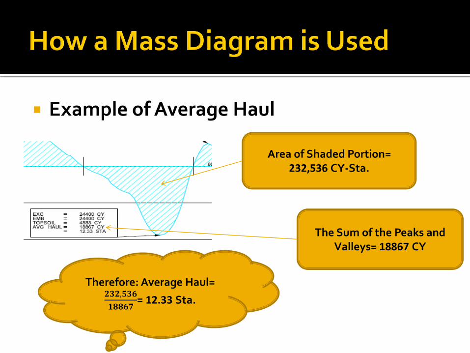
Example of Average Haul
Area of Shaded Portion= 232,536 CY-Sta.
The Sum of the Peaks and Valleys= 18867 CY
Therefore: Average Haul= 𝟐𝟑𝟐,𝟓𝟑𝟔
𝟏𝟖𝟖𝟔𝟕= 12.33 Sta.

Calculation of Average or Free Haul The equation for average or free haul for the
entire project is as follows
𝐴𝑣𝑒𝑟𝑎𝑔𝑒 𝐻𝑎𝑢𝑙 𝑃𝑟𝑜𝑗𝑒𝑐𝑡 = 𝐴𝑟𝑒𝑎𝑠
𝑃𝑒𝑎𝑘𝑠/𝑉𝑎𝑙𝑙𝑒𝑦𝑠
Areas= CY-Sta. Peaks/Valleys= CY The resulting number will be in Sta.

Calculation of Average or Free Haul With the average haul value, you can
determine when and where to pay for overhaul.
When you exceed this average haul distance, you must begin paying for overhaul with a few exceptions.

Definitions Overhaul- the authorized hauling of
excavation beyond the specified free-haul distance.
Free haul=Average haul for project
Overhaul distance= (Distance between centers of gravity) – (Free haul distance)

Overhaul Exceptions Overhaul is paid for when you exceed the
average or free haul distance. Overhaul is only paid if you are outside of the
balance points. This means that if your average or free haul
distance is exceeded within the balance point, you do NOT have to pay for overhaul.

Borrow When using borrow, the dead haul is not
included in calculations. The mass is entered into the diagram where it enters into the project.
This is represented by a vertical line.

What We Covered Earthwork- cross sections, quantities,
average end area method, topsoil, shrinkage. Mass Diagrams- mass ordinates, plot of mass
diagram. How a Mass Diagram is Used- haul, average
haul, how to calculate average haul, overhaul, borrow.

Questions?