earthwork and ground technology site improvement · earthwork and ground technology site...
TRANSCRIPT

Earthwork and Ground Technology
Site Improvement
Slides adapted and upgraded from original presentation slide by College of Engineering, University of Washington.
Methods of site improvement
• Removal and replacement• Preloading• Vertical drains• In-situ densification• Grouting• Stabilization using admixtures• Reinforcement
Removal and replacement
• One of oldest and simplest methods is simply to remove and replace the soil
• Soils that will have to be replaced include contaminated soils or organic soils
• Method is usually practical only above the groundwater table
Preloading
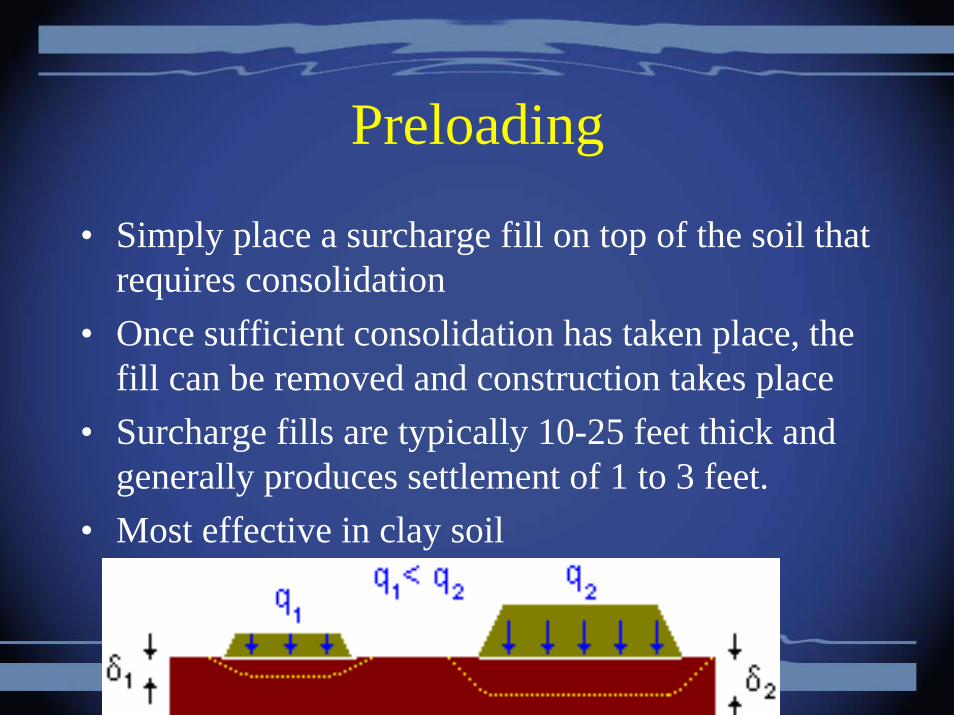
• Simply place a surcharge fill on top of the soil that requires consolidation
• Once sufficient consolidation has taken place, the fill can be removed and construction takes place
• Surcharge fills are typically 10-25 feet thick and generally produces settlement of 1 to 3 feet.
• Most effective in clay soil
Advantages of preloading
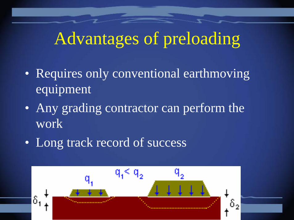
• Requires only conventional earthmoving equipment
• Any grading contractor can perform the work
• Long track record of success
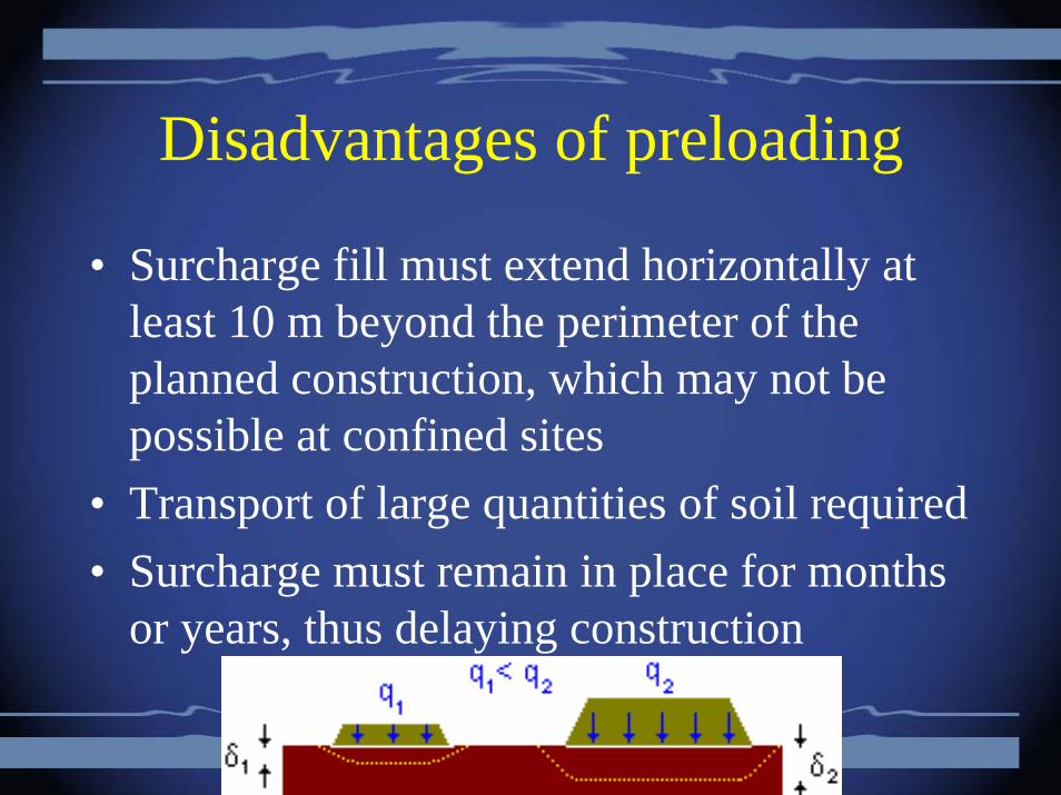
Disadvantages of preloading
• Surcharge fill must extend horizontally at least 10 m beyond the perimeter of the planned construction, which may not be possible at confined sites
• Transport of large quantities of soil required• Surcharge must remain in place for months
or years, thus delaying construction
Vertical Drains
• Vertical drains are installed under a surcharge load to accelerate the drainage of impervious soils and thus speed up consolidation
• These drains provide a shorter path for the water to flow through to get away from the soil
• Time to drain clay layers can be reduced from years to a couple of months

Vertical Drains
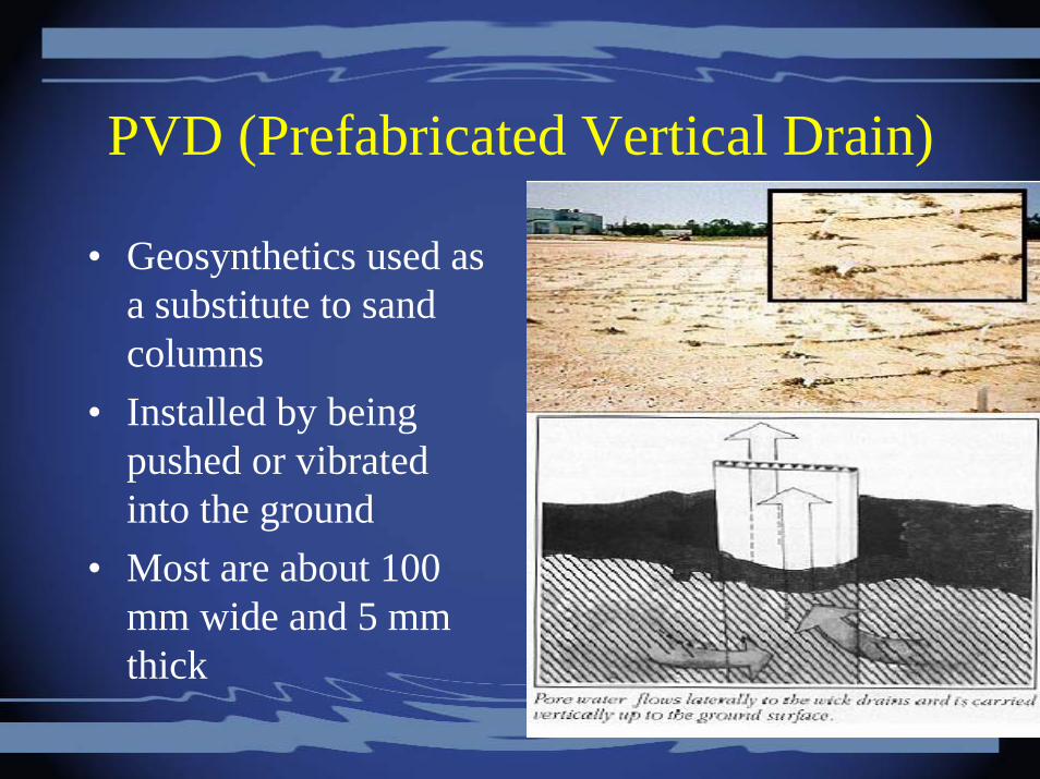
PVD (Prefabricated Vertical Drain)
• Geosynthetics used as a substitute to sand columns
• Installed by being pushed or vibrated into the ground
• Most are about 100 mm wide and 5 mm thick

Vertical Drain Installation
Photo from: http://www.joostdevree.nl/bouwkunde/vertical_drain_2_www_imtek_com_tr.jpg
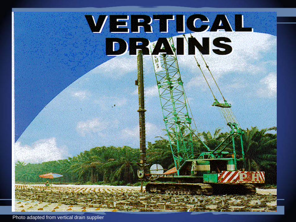
Photo adapted from vertical drain supplier

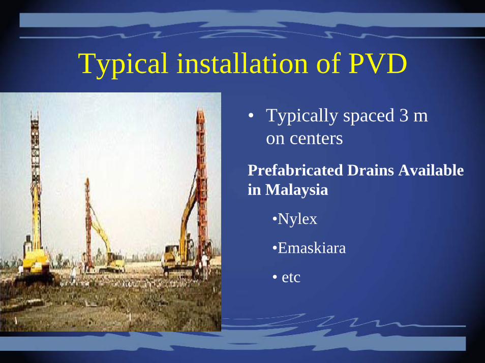
Typical installation of PVD• Typically spaced 3 m
on centers
Prefabricated Drains Available in Malaysia
•Nylex
•Emaskiara
• etc
In-situ densification
• Most effective in sands• Methods used in conventional earthwork are
only effective to about 2 m below the surface
• In-situ methods like dynamic deep compaction are for soils deeper than can be compacted from the surface
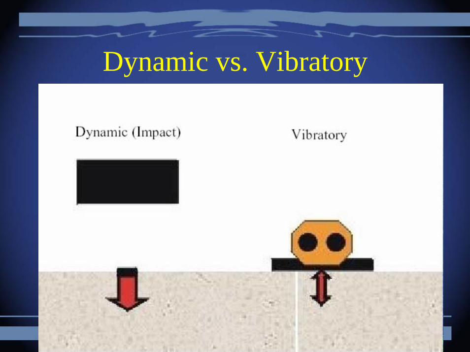
Dynamic vs. Vibratory
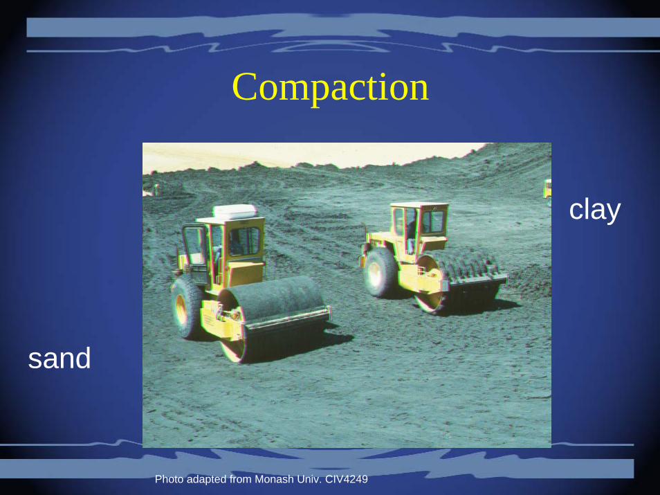
Compaction
sand
clay
Photo adapted from Monash Univ. CIV4249
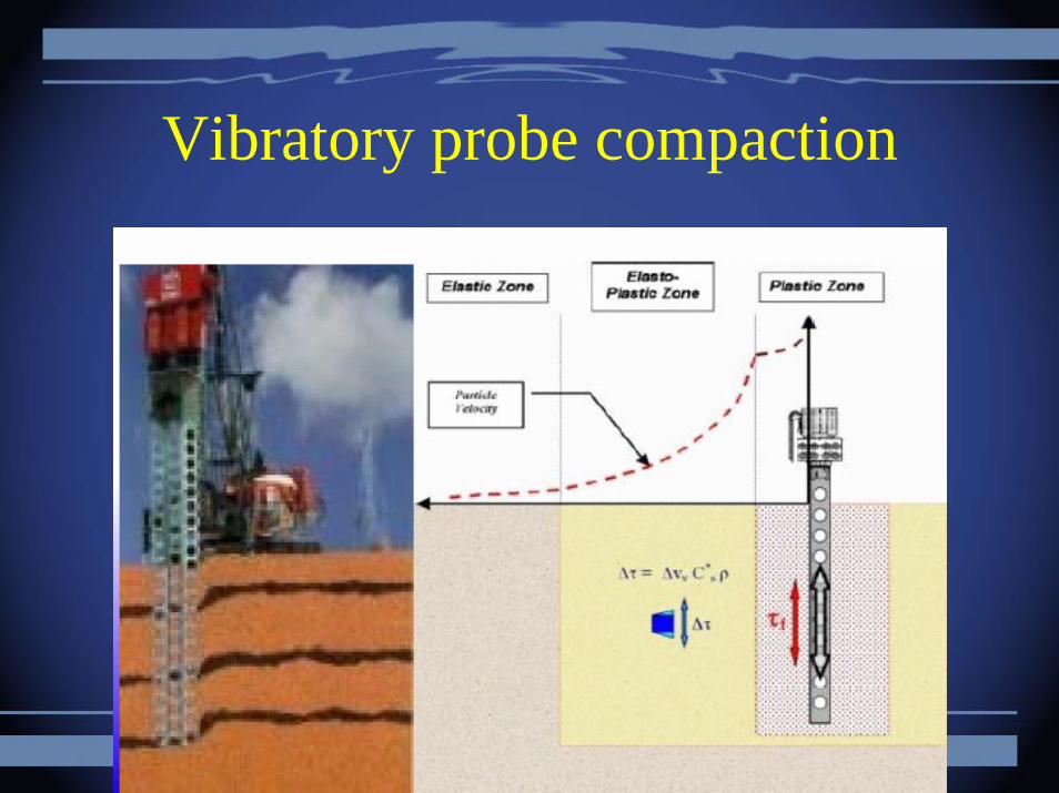
Vibratory probe compaction
• Long probe mounted onto a vibratory pile driver compacts the soil around the probe; penetrations spaced in a grid pattern similar to vertical drains
Vibratory probe compaction
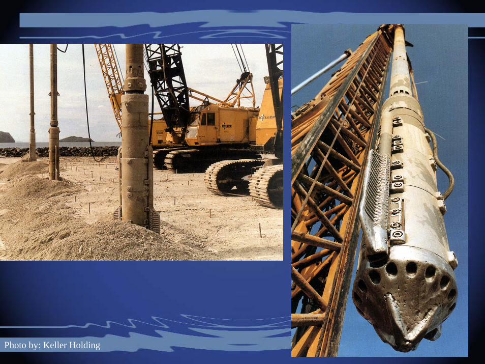
Photo by: Keller Holding
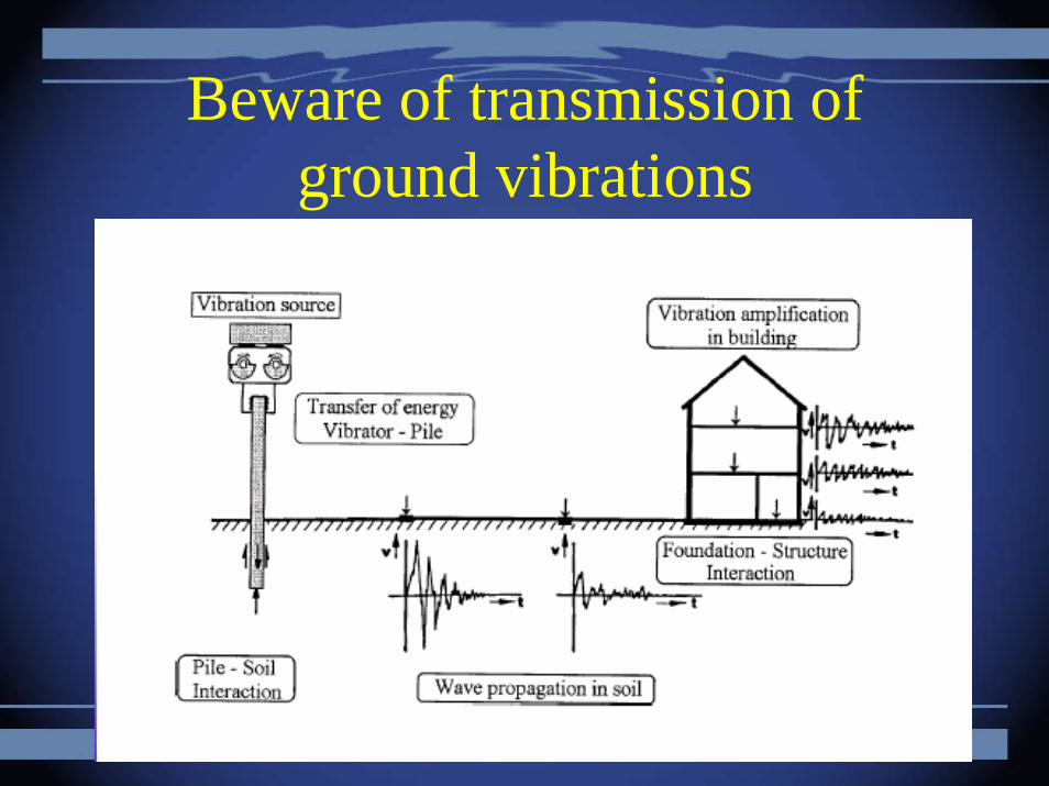
Beware of transmission of ground vibrations

Vibroflotation
• Probe includes the vibrator mechanism and water jets
• Probe is lowered into the ground using a crane• Vibratory eccentric force induces densification
and water jets assist in insertion and extraction • Vibratory probe compaction is effective if silt
content is less than 12-15% and clay is less than 3%
• Probes inserted in grid pattern at a spacing of 1.5 to 3 m
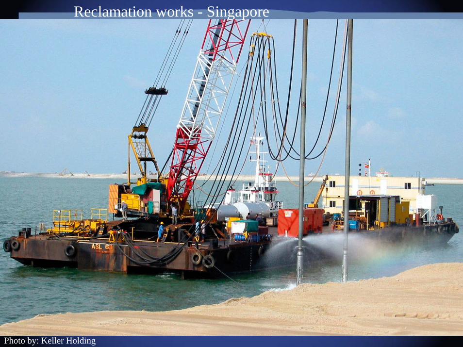
Photo by: Keller Holding
Reclamation works - Singapore
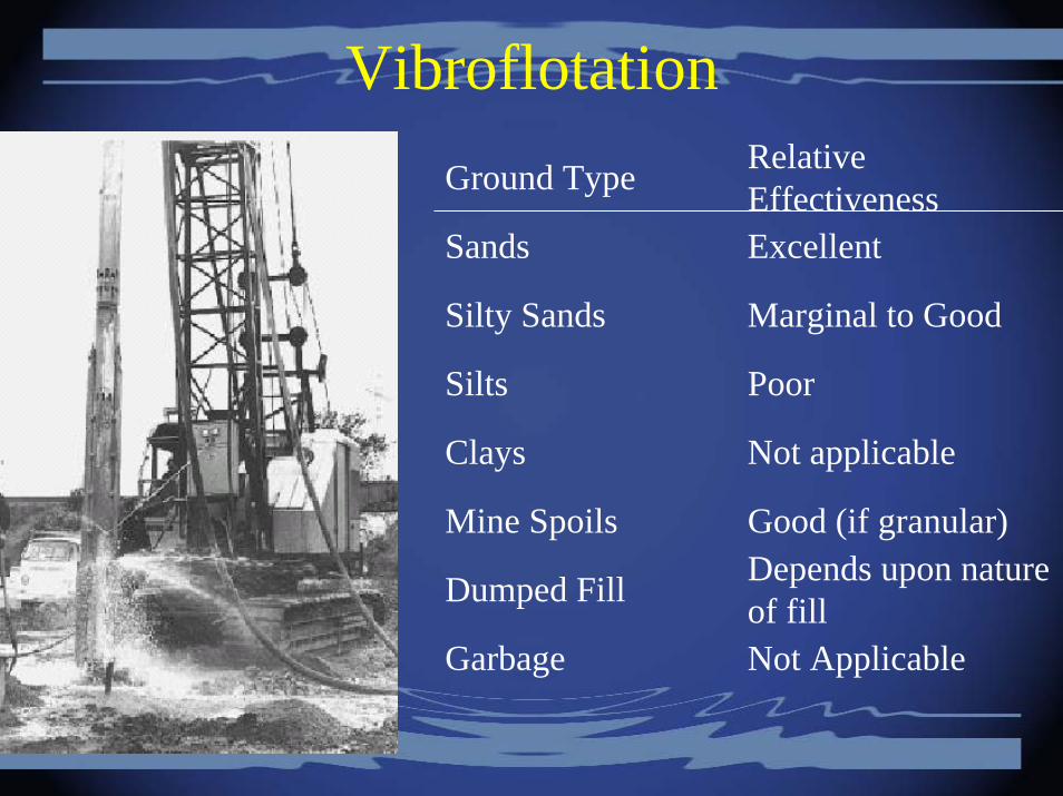
VibroflotationGround Type Relative
Effectiveness Sands Excellent
Silty Sands Marginal to Good
Silts Poor
Clays Not applicable
Mine Spoils Good (if granular)
Dumped Fill Depends upon nature of fill
Garbage Not Applicable
Vibro-replacement stone columns
• Vibro-Replacement extends the range of soils that can be improved by vibratory techniques to include cohesive soils. Reinforcement of the soil with compacted granular columns or "stone columns" is accomplished by the top-feed method.
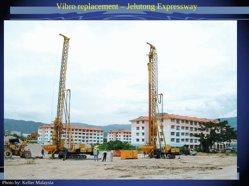
Vibro replacement – Jelutong Expressway
Photo by: Keller Malaysia

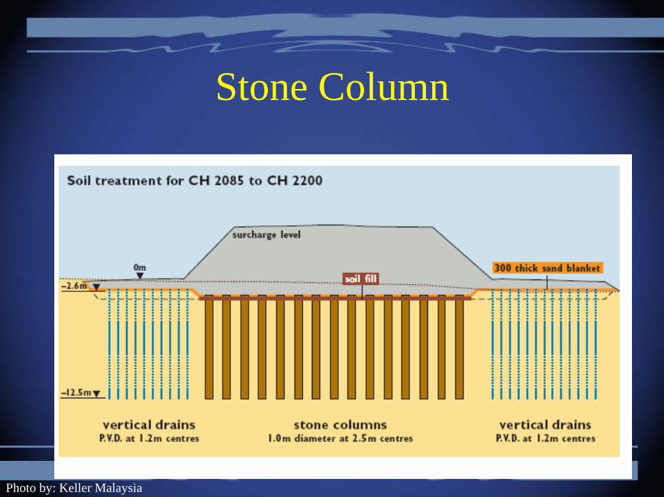
Stone Column
Photo by: Keller Malaysia
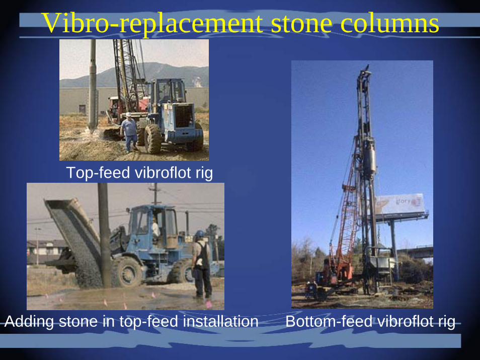
Top-feed vibroflot rig
Adding stone in top-feed installation Bottom-feed vibroflot rig
Vibro-replacement stone columns
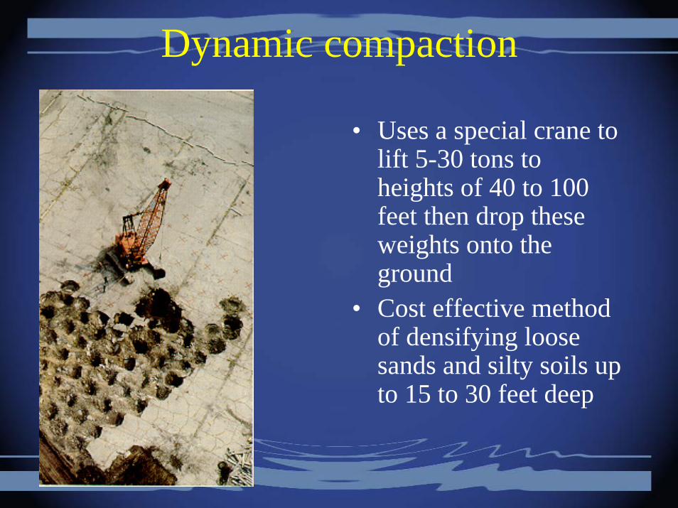
Dynamic compaction
• Uses a special crane to lift 5-30 tons to heights of 40 to 100 feet then drop these weights onto the ground
• Cost effective method of densifying loose sands and silty soils up to 15 to 30 feet deep
Grouting
• Defined as the injection of a special liquid or slurry material called grout into the ground for the purpose of improving the soil or rock
• Types of grouts– Cementitious grouts– Chemical grouts
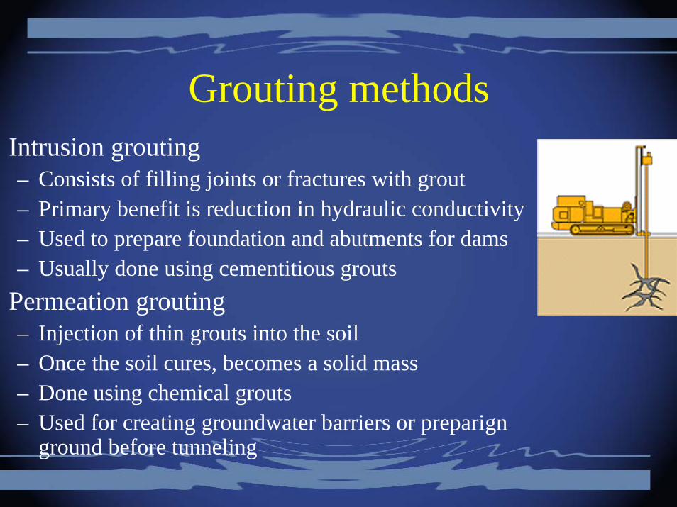
Grouting methodsIntrusion grouting– Consists of filling joints or fractures with grout– Primary benefit is reduction in hydraulic conductivity– Used to prepare foundation and abutments for dams– Usually done using cementitious grouts
Permeation grouting– Injection of thin grouts into the soil– Once the soil cures, becomes a solid mass– Done using chemical grouts– Used for creating groundwater barriers or preparign
ground before tunneling
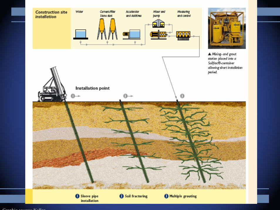
Graphic source: Keller
Grouting methods
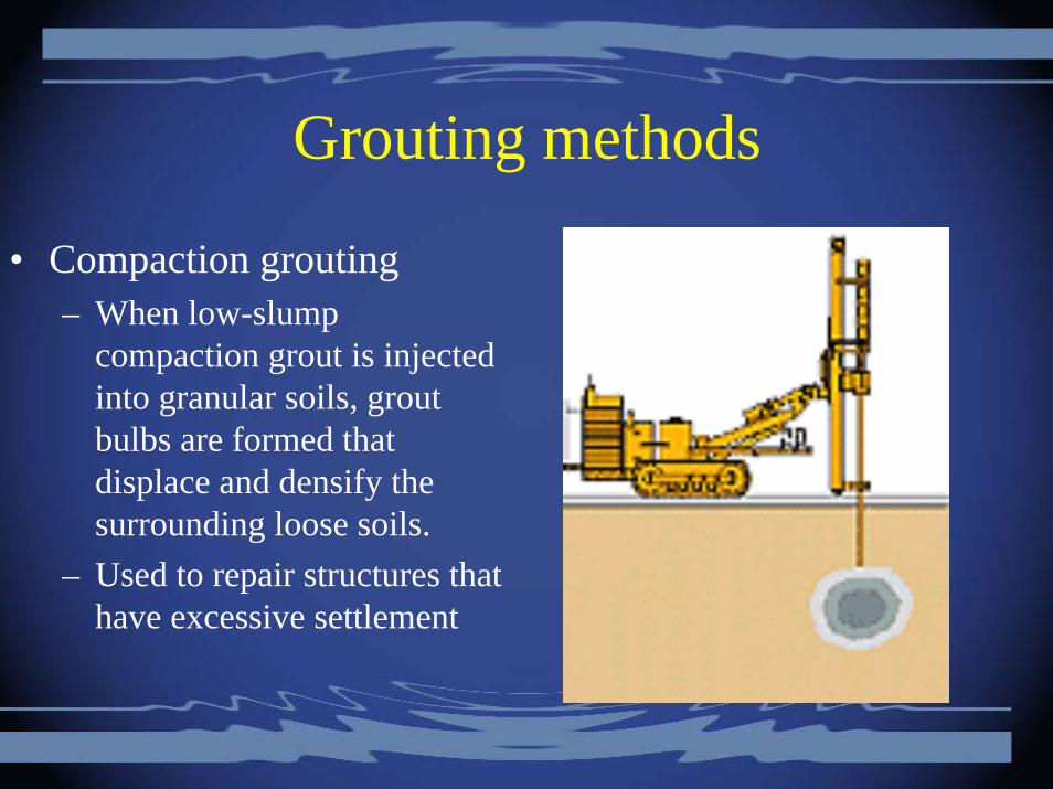
• Compaction grouting– When low-slump
compaction grout is injected into granular soils, grout bulbs are formed that displace and densify the surrounding loose soils.
– Used to repair structures that have excessive settlement
Grouting methods
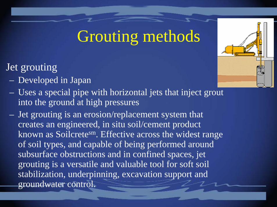
Jet grouting– Developed in Japan– Uses a special pipe with horizontal jets that inject grout
into the ground at high pressures– Jet grouting is an erosion/replacement system that
creates an engineered, in situ soil/cement product known as Soilcretesm. Effective across the widest range of soil types, and capable of being performed around subsurface obstructions and in confined spaces, jet grouting is a versatile and valuable tool for soft soil stabilization, underpinning, excavation support and groundwater control.

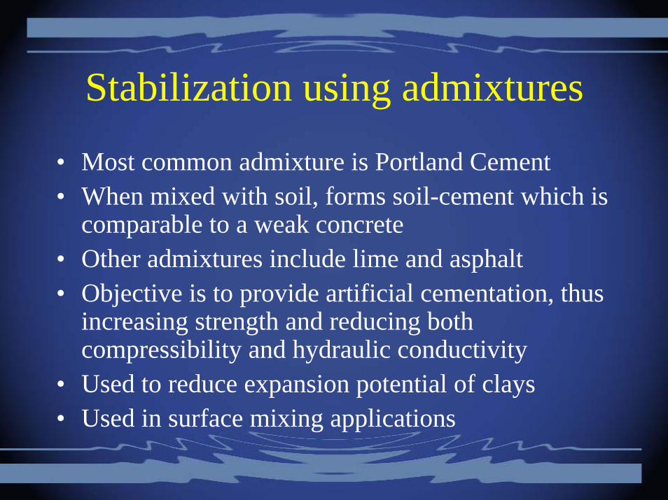
Stabilization using admixtures
• Most common admixture is Portland Cement• When mixed with soil, forms soil-cement which is
comparable to a weak concrete• Other admixtures include lime and asphalt• Objective is to provide artificial cementation, thus
increasing strength and reducing both compressibility and hydraulic conductivity
• Used to reduce expansion potential of clays• Used in surface mixing applications
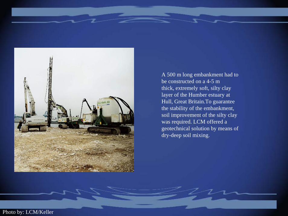
A 500 m long embankment had to be constructed on a 4-5 mthick, extremely soft, silty clay layer of the Humber estuary atHull, Great Britain.To guarantee the stability of the embankment,soil improvement of the silty clay was required. LCM offered ageotechnical solution by means of dry-deep soil mixing.
Photo by: LCM/Keller

Reinforcement• Soil is stronger in compression than in
tension• To improve strength in tension,
geosynthetics placed in soil for soil reinforcement
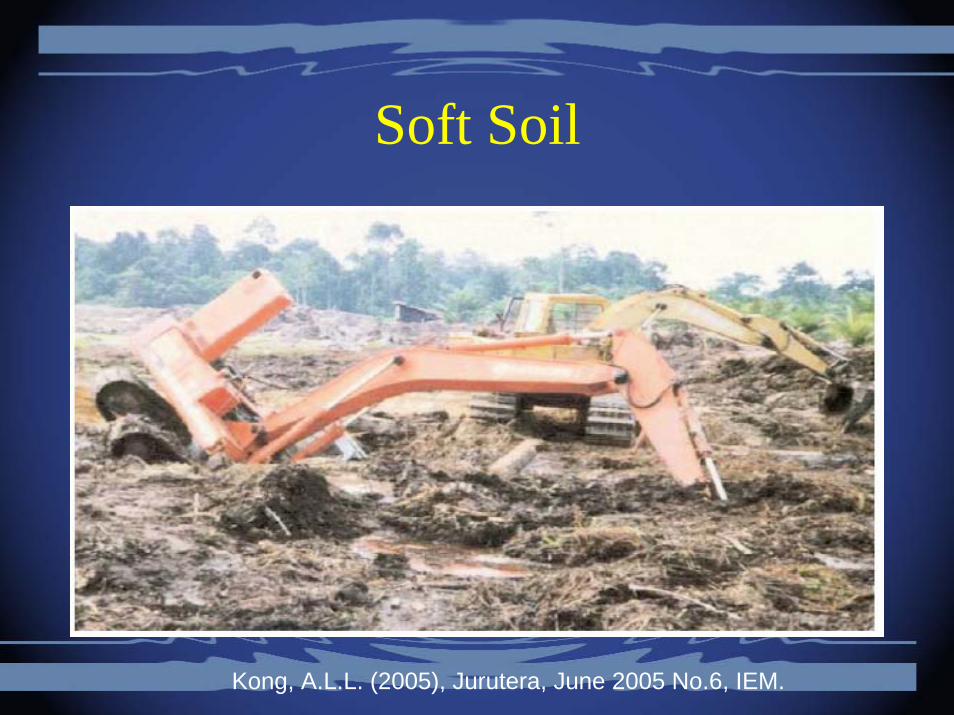
Soft Soil
Kong, A.L.L. (2005), Jurutera, June 2005 No.6, IEM.
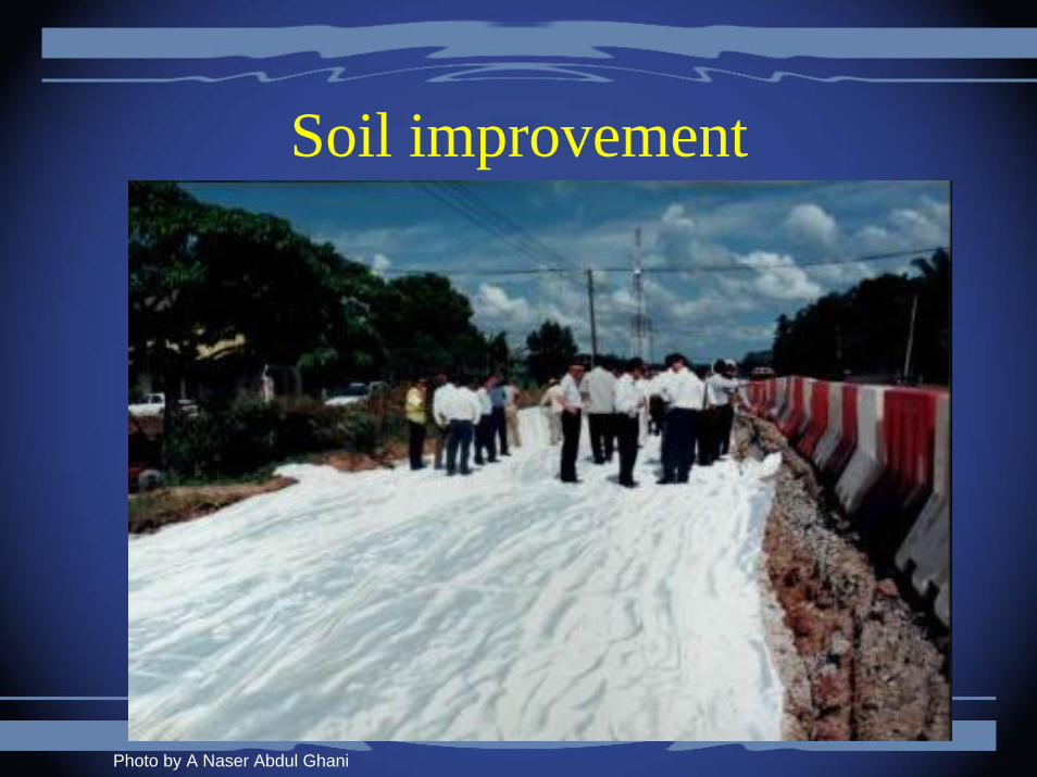
Soil improvement
Photo by A Naser Abdul Ghani
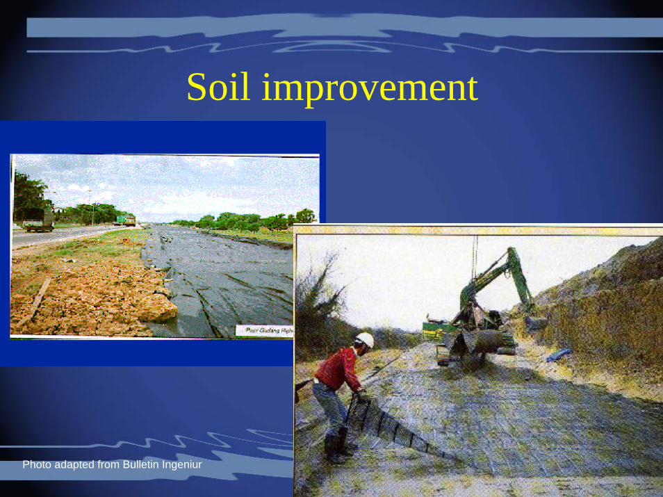
Soil improvement
Photo adapted from Bulletin Ingeniur
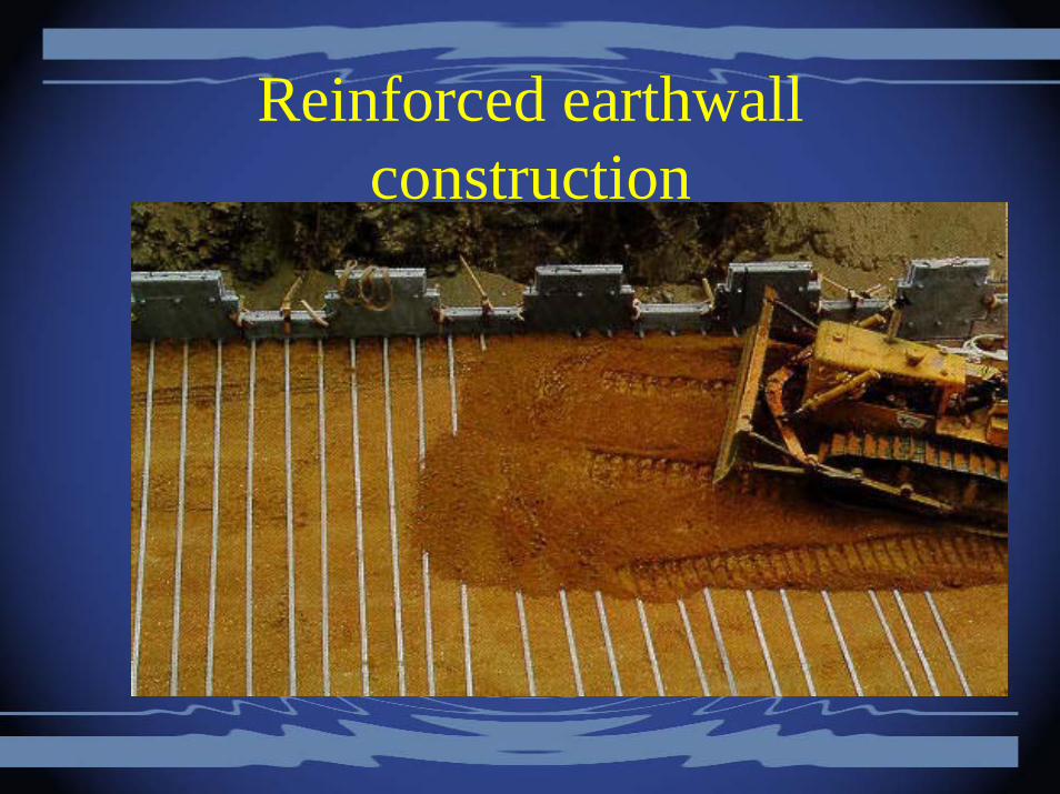
Reinforced earthwallconstruction
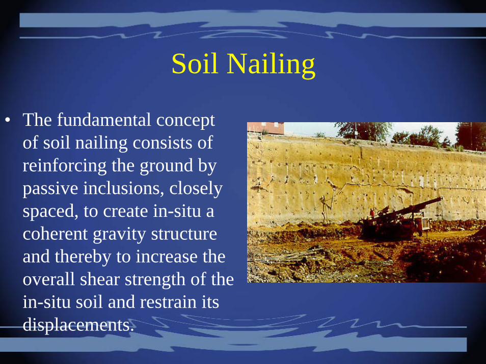
Soil Nailing
• The fundamental concept of soil nailing consists of reinforcing the ground by passive inclusions, closely spaced, to create in-situ a coherent gravity structure and thereby to increase the overall shear strength of the in-situ soil and restrain its displacements.

Photo by A Naser Abdul Ghani