earthquake resistant residential design and construction ... 232 chapters 5-7.pdf ·...
TRANSCRIPT

Earthquake Resistant Residential Design and Construction, Part 2 Course No: S05-007
Credit: 5 PDH
John L. Galinski, PE
Continuing Education and Development, Inc. 9 Greyridge Farm Court Stony Point, NY 10980 P: (877) 322-5800 F: (877) 322-4774 [email protected]


of the National Institute of Building Sciences
Homebuilders’ Guide to Earthquake-Resistant Design and Construction FEMA 232 ─ June 2006
Prepared by the Building Seismic Safety Council for the Federal Emergency Management Agency of the Department of Homeland Security
National Institute of Building Sciences Washington, D.C.
Chapter 5 WALLS
5.1 WOOD LIGHT-FRAME CONSTRUCTION
5.1.1 General Components
In residential construction, the walls provide the primary lateral resistance to wind and earthquake loads. Even in frame type houses (e.g., post-beam construction), the exterior walls provide most of the lateral stability to the house. Although this guide focuses on wood light-frame construction, alternatives such as cold-formed steel, masonry, and concrete construction are used in many regions of the country. The reader is referred to the sections on masonry and concrete construction later in this chapter for some guidance on the use of these materials. For cold-formed steel construction, the reader is referred to the American Iron and Steel Institute’s (AISI) industry standard for prescriptive cold-formed steel construction, Standard for Cold-formed Steel Framing Prescriptive Method for One- and Two-Family Dwellings (2001).
Light-frame walls provide resistance to sliding, overturning, and racking loads induced in the house by an earthquake as illustrated in Figure 5-1. The walls are the principle element for transmitting the loads from the upper stories and roof to the foundation. The concept of how these loads are transferred between the major components of the house is illustrated in Figure 5-2, and the action of the individual wall segments resisting the lateral loads is illustrated in Figure 5-3. Wood light-frame walls typically consist of the lumber framing covered by sheathing material that is attached to the wood framing with nails, staples, or screws. Figure 5-4 illustrates the components of a wall that is sheathed with wood structural panels (OSB or plywood) on the outside and gypsum wallboard on the inside. The figure also shows the addition of hold-down connectors to the framing, which are required by the IRC for some specific bracing configurations. When used, hold-down connectors increase the strength and stiffness of the wall segment.
Four different bracing wall configurations and eight methods (materials) are recognized by the IRC. The bracing wall configurations include:
• IRC Section R602.10.3 braced wall panels (Figure 5-5a), • IRC Section R602.10.5 continuous (wood) structural panel sheathing (Figure 5-5b), • IRC Section 602.10.6 alternate braced wall panels (similar to Figure 5-5c), and • Wood structural panel sheathed walls with hold-down connections as required by the
exceptions in IRC Section R703.7 when stone or masonry veneer is used (Figure 5-5c).
83

FEMA 232, Homebuilders’ Guide
Figure 5-1 Sliding, overturning, and racking action resisted by walls and foundation.
84

Chapter 5, Walls
Figure 5-2 Exploded view of house illustrating load paths.
85

FEMA 232, Homebuilders’ Guide
Figure 5-3 Wall action for resisting lateral loads
Figure 5-4 Exploded view of typical residential wall segment.
86

Chapter 5, Walls
Differences in these bracing wall configurations include sheathing materials, minimum bracing length, extent of sheathing, and anchorage at the wall base. Differences in overturning anchorage for walls are shown in Figure 5-5.
Figure 5-5 Detailing differences for three options when using wood structural panel sheathed walls.
The braced wall panel (IRC Section R602.10.3) is the most commonly used approach. Eight different methods (materials) are recognized by the IRC as acceptable bracing. These are called “braced wall panel construction methods” in the IRC and are listed in Table 5-1. Method 1, let-in bracing, is not allowed to be used in regions of high earthquake hazard because it often will fail as the walls are racked during an earthquake; therefore, this method is not discussed further in this guide.
Of the acceptable braced wall panel materials, wood structural panels and diagonal lumber sheathing are known to perform better than others (i.e., withstand higher deformations while supporting higher loads). Wall panel bracing is required by IRC Section R602.10.4 to be provided in 4-foot minimum lengths sheathed on one face for other than Method 5 and either 4-foot lengths sheathed on both faces or 8-foot lengths sheathed on one face for Method 5. Other than with Method 5, this bracing often is provided in 4-foot-long isolated segments along the wall length.
87

FEMA 232, Homebuilders’ Guide
Table 5-1 Braced Wall Panel Construction Methods (Materials) Recognized by the IRC Construction Method Designation Sheathing Material
1 Nominal 1x4 inch continuous let-in bracing 2 5/8-inch minimum thickness boards applied diagonally to
studs 3 Wood structural panels (OSB or plywood) 5/16-inch
minimum thickness 4 1/2- or 25/32-inch thick structural fiberboard 5 1/2-inch gypsum wallboard 6 Particleboard sheathing 7 Portland cement plaster 8 Hardboard panel siding
Where braced wall panels use wood structural panel (Method 3) or diagonal lumber (Method 2) sheathing, the panel base anchorage to the supporting floor framing or foundation limits the bracing strength and stiffness. The braced wall panel anchorage includes two critical weak links for uplift: the panel end stud connection and the bottom plate (sole plate) connection. Braced wall panel bottom plates are specified by IRC Table R602.3(1) to be attached to the floor platform using three 16d common (0.162 x 3.5 inch) or 16d box (0.148 x 3.5 inch) nails every 16 inches or are specified by IRC Section R403.1.6 to be anchored to the foundation with 1/2-inch-diameter anchor bolts at not more than 6 feet on center. Together, these two weak links cause the wall to fail along the bottom of the wall under relatively low loads (these walls have a capacity of approximately 150 to 400 plf, which translates to an allowable design value of about 50 to 140 plf maximum).
IRC Section R602.10.5, continuous structural panel sheathing, requires that all exterior wall surfaces on a given story level other than door and window openings be sheathed with wood structural panel sheathing (Figure 5-5b). This bracing wall configuration has greater strength and stiffness than braced wall panels with minimum wall base anchorage. The increased strength and stiffness are due in part to the continuity provided by additional sheathing above and below windows and doors (which makes the wall-base connection capacity less critical) and increased overturning capacity due to required corner framing details or hold-downs at wall ends. In recognition of the improved strength and stiffness provided with continuous structural panel sheathing, IRC Section R602.10.5 permits the minimum length of bracing to be reduced and IRC Table R602.10.5 permits use of individual wall bracing panels that are more slender than would otherwise be permitted.
Wood structural panel wall bracing with uplift anchorage provided at each end, per IRC Sections R602.10.6 and R703.7, is the strongest and stiffest option for resisting lateral loads. This wall configuration is illustrated in Figure 5-5c. Although sheathing, fastening, and hold-down loads for these walls are prescribed, the walls are essentially equivalent to engineered shear walls. The alternate braced wall panel provisions of IRC Section R602.10.6 were developed to allow use of braced wall panels narrower than the 4-foot minimum required by IRC Section R602.10.4 (e.g., at the side of garage doors); however, the IRC permits an alternate braced panel to be substituted for each 4 feet of bracing throughout the house. The provisions of IRC Section R703.7 use
88

Chapter 5, Walls
increased wall strength and stiffness to compensate for the increased earthquake loads that occur due to the weight of stone or masonry veneer. As discussed above, where wood structural panel bracing is used, the strength and stiffness of the wall bracing is very dependent on the extent of sheathing and anchorage at the wall base. The configuration shown in Figure 5-5a, using IRC minimum braced wall panel anchorage, is the weakest and least stiff of the wood structural panel bracing configurations. The configuration shown in Figure 5-5b adds strength and stiffness by providing continuous structural panel sheathing and added detailing or tie-downs at wall ends. The strongest and stiffest configuration is illustrated in Figure 5-5c where overturning anchors are provided at each end of each wall segment.
Above-code Recommendation: Use of the configurations shown in Figures 5-5b or 5-5c can significantly increase the strength and stiffness of braced wall panels sheathed with wood structural panel or diagonal lumber sheathing and may be used to provide improved performance whether or not specifically required by the IRC. Use with sheathing materials other than Methods 2 or 3 would provide less benefit and is not recommended.
When the wood structural panel wall bracing option is used in an engineered design, the walls are designed according to empirical tables that provide allowable design loads in pounds per foot of wall depending on the thickness and grade of the sheathing and the size and spacing of the sheathing nails. These walls rely on hold-down anchor connections to resist the overturning loads and substantial connections (nails, lag screws, bolts, etc.) along the top and bottom plates to transmit the lateral loads between the wall framing and the floor platform or foundation. This type of wall can resist allowable design loads up to 870 plf when sheathed on one face with wood structural panels.
5.1.2 Design Requirements
The 2003 IRC requires that wall bracing be provided both at exterior walls and at interior braced wall lines. IRC Section R602.10.1.1 specifies that interior braced wall lines must be added such that the distance between braced wall lines does not exceed 35 feet; however, allowance is made for spacing up to 50 feet. IRC Section R602.10.11 reduces the maximum spacing to 25 feet in SDCs D1 and D2. Within each braced wall line, IRC Table R602.10.1 specifies the minimum bracing as a percentage of the length of the wall line based on the wind and earthquake exposure and the story level under consideration (the lower in the house, the more sheathing is required to resist the higher loads). Some interpretations of the IRC would allow a house located in SDC C to be braced according to the amounts required for SDCs A and B due to the exemption for detached houses in SDC C from all earthquake requirements.
Above-code Recommendation: Houses in SDC C should be braced according to the requirements of SDC D1. Use of the required percentage of wall bracing in each 25-foot length of wall will provide a distributed resistance system of walls rather than a concentrated wall system. Experience has shown that a distributed wall system performs better in an earthquake than concentrated walls in only a few locations.
89

FEMA 232, Homebuilders’ Guide
Table 5-2 excerpts a portion of this bracing information. As previously noted, the amount of bracing may be modified in accordance with IRC Section R602.10.5 when continuous wood structural panel sheathing is provided. In addition, an alternate braced wall panel (per IRC Section R602.10.6) can be substituted for each 4 feet of braced wall panel. The sheathing must be located at the ends of each braced wall line at least 25 feet on center. The idea is to provide a distributed resisting system rather than to concentrate the resistance in a few highly loaded wall segments. Overall, this provides a more robust structure that can resist the loads induced into the house close to the source of the load and not require the floor and roof diaphragms to transmit the loads long distances. Let-in bracing is allowed only for the top story of houses in SDC C due to its tendency to fail at relatively low lateral load levels.
Table 5-2 IRC Sheathing Requirements for Seismic Design Categories C, D1, and D2 Seismic Design
Category Floor Level Sheathing Requirements
C
Top story 16% of wall line for wood structural panel and 25% for all other sheathing types
First story of 2-story or second story of 3-story
30% of wall line for wood structural panel and 45% for all other sheathing types
First story of 3-story 45% of wall line for wood structural panel and 60% for all other sheathing types
D1
Top story 20% of wall line for wood structural panel and 30% for all other sheathing types
First story of 2-story or second story of 3-story
45% of wall line for wood structural panel and 60% for all other sheathing types
First story of 3-story 60% of wall line for wood structural panel and 85% for all other sheathing types
D2
Top story 25% of wall line for wood structural panel and 40% for all other sheathing types
First story of 2-story or second story of 3-story
55% of wall line for wood structural panel and 75% for all other sheathing types
First story of 3-story Not allowed prescriptively must use IBC design methods
Cripple walls 75% of wall line using wood structural panel sheathing only
Although the basic IRC bracing concept is reasonably straightforward, a number of other adjustments may modify the required length of bracing. Close attention is required to ensure that the IRC requirements are met. IRC Section R301.2.2.2.1 limits the dead load of assemblies for houses in SDCs D1 and D2. The maximum permitted for roof plus ceiling dead load is 15 psf (typical asphalt shingle roofs with gypsum ceilings); however, IRC Table R301.2.2.2.1 permits this assembly weight to be increased to 25 psf (for heavier roofing materials) provided that the length of wall bracing is increasd as specified. Footnote d to IRC Table R602.10.1 notes that the earthquake bracing requirements are based on 15 psf (exterior) wall dead load and permits the required earthquake bracing length to be multiplied by 0.85 for walls with dead loads of 8 psf or
90

Chapter 5, Walls
less, provided that the length is not less than required by IRC Section R602.10.4 (4 feet for all but let-in bracing and gypsum board, which require a length of 8 feet) nor less than required for wind loading.
In addition to the adjustments to required bracing length, the second paragraph of IRC Section R602.10.11 (errata, second printing) permits the wood structural panel wall sheathing to begin up to 8 feet from the corner in SDCs D1 and D2 provided that:
• A 2-foot braced panel is applied in each direction at the house corner or • Tie-downs are provided at the end of the braced wall panel closest to the corner.
This is more stringent than for low SDCs where braced wall panels are permitted to be located up to 12 feet 6 inches from wall corners without providing tiedowns or sheathed corners and farther from corners if collectors are provided to carry loads to the braced wall panels. However, a house that is tied together at the corners will resist the loads expected from an earthquake much better than if the corners are not connected well. When using bracing other than wood structural panels in SDCs D1 and D2, braced wall panels must be located at each end of braced wall lines.
Above-code Recommendation: Braced wall panels should extend to every corner.
IRC Section R703.7 presents additional bracing modifications where exterior veneer is used. These requirements are discussed in Section 5.2 of this guide. For the guide’s model house, Figures 5-6a through 5-6c provide plan views identifying the bracing required when the house is in SDC C, has a light finish system such as vinyl siding, and has a crawl space. The bracing requirements for the same house located in SDC D2 are shown in Figures 5-7a through 5-7c. Notice the significant increase in designated wall bracing due to the higher level loads expected in SDC D2.
91

FEMA 232, Homebuilders’ Guide
Figure 5-6a Plan view of crawl space for model house with light-weight finish material located in SDC C.
92

Chapter 5, Walls
Figure 5-6b Plan view of first floor for model house with light-weight finish material located in SDC C.
93

FEMA 232, Homebuilders’ Guide
Figure 5-6c Plan view of second floor for model house with light-weight finish material located in SDC C.
94

Chapter 5, Walls
Figure 5-7a Plan view of crawl space for model house with light-weight finish material located in SDC D2.
95

FEMA 232, Homebuilders’ Guide
Figure 5-7b Plan view of first floor for model house with light-weight finish material located in SDC D2.
96

Chapter 5, Walls
Figure 5-7c Plan view of second floor for model house with light-weight finish material located in SDC D2.
97

Figure 5-8 Properly driven and overdriven nails.
FEMA 232, Homebuilders’ Guide
5.1.3 Cripple Walls
Cripple walls are short frame walls that extend from the foundation to the bottom of the first floor. They are most often found in the western United States. These walls often enclose a crawl space or serve as walls for a stepped foundation. Historically, these walls have been the cause of significant failures in residential construction during earthquakes primarily due to inadequate in-plane strength or inadequate anchorage to the foundation. These walls are the most highly loaded of all the light-frame walls in a house because they have to resist the entire load from the house above. For cripple walls, IRC Section R602.10.2.1 specifies the length of bracing as 1.15 times the bracing required for the story above and indicates that the spacing should be 18 feet instead of 25 feet. This is not applicable in SDC D2, however, where the IRC requires that the cripple wall bracing be a minimum of 75 percent of the wall length and be constructed using wood structural panels. When interior braced wall lines are not supported on a continuous foundation, cripple wall bracing lengths in SDCs D1 and D2 must be modified to increase the sheathing length by 50 percent at exterior braced wall lines or to decrease the nail spacing along sheathing edges to 4 inches on center (per IRC Section R602.10.11.1).
5.1.4 Quality Assurance
Quality assurance for the typical light-frame wall is really quite simple. There are essentially three areas to inspect:
• The sheathing nails, • The anchorage of the framing to the floor framing or foundation below, and • The anchorage of the wall framing to the roof or floor framing above.
The most common problem that adversely affects the performance of all wall types is the overdriving of the nails attaching the sheathing to the studs; this is especially a problem when pneumatic or power-driven nail guns are used. All of the nails used to attach the sheathing to the wall framing should be driven only to where the nail head is flush with the surface of the sheathing as shown in Figure 5-8; an improperly driven (overdriven) nail also is shown in Figure 5-8.
Figure 5-8 Properly and overdriven nails.
98

Chapter 5, Walls
The most important nails are those around the perimeter of each panel of sheathing. These nails govern the strength and stiffness of the panel. If the nails are overdriven (as in Figure 5-8), the strength of the connection is severely compromised. For instance, if 3/8-inch wood structural panel sheathing is used and the nails are overdriven 1/8 inch (typical for many pneumatic nail tools), the strength of the wall is reduced as much as 40 to 50 percent. It is therefore imperative that the sheathing nails be inspected to ensure that they are properly driven. Many pneumatic nail tools have default driving pins that overdrive the nails but changing the driving pin costs little (less than 10 percent of the original cost of the tool). Many tool manufacturers now provide an adjustment on the tool to allow the user to change the depth of the driving pin without replacing the part. (It is recommended that where nail heads occasionally are more than 1/16-inch below the surface, an additional nail should be provided between existing nails. If a substantial number of nails are overdriven, the sheathing should be removed and the framing checked for splitting before replacing the sheathing with proper nailing.)
Nails often are located too close to the edge of the sheathing panel, which can result in the nails tearing out the side of the panel and weakening the wall. Therefore, the minimum edge distance for nailing sheathing is 3/8 inch. The larger the edge distance is, the stronger the wall will be. This is especially true for the row of nails at the bottom of the wall. If the bottom row of nails is located at the mid-height of the bottom plate for the wall, the displacement capacity of the wall is almost double that when the nails are spaced at 3/8 inch. When the edges of two sheathing panels meet on a common stud (2x nominal), the maximum edge distance should be 3/8 inch to prevent the nail from splitting the edge of the stud behind the sheathing.
Another common problem is that the nails are driven through the sheathing but miss the stud behind. Although it is obvious that nails in the air provide no strength or stiffness, this problem is so common it merits emphasizing that sheathing nails must be driven into the studs and top and bottom plates of the wall and not miss the framing. The use of pneumatic nail guns makes it very difficult for the operator to “feel” whether or not the nail has been driven into the stud behind; therefore, all such nailing must be visually inspected from behind to ensure that the nails did not miss the studs.
Finally, the sheathing nailing around the perimeter of each sheet of sheathing should be symmetric about the center of the sheathing panel. This means that there should be approximately the same number of nails along each parallel side of the panel as illustrated in Figure 5-9.
The second area to inspect for quality assurance is the anchorage at the bottom of the wall. For prescriptive walls, the nails must pass through the bottom plate into the floor framing. If the nails miss the floor joists, they have no capacity to resist withdrawal and sliding. If the wall is attached directly to the foundation, 1/2-inch-diameter anchor bolts should be spaced at a maximum of 6 feet on center, and the end bolts should be not more than 12 inches nor closer than 7 bolt diameters from the end of the plate. If the house is located in SDC D1 or D2, the anchor bolts are required to have a steel plate washer between the wood sill plate and the nut. (See Section 3.10 of this guide for more discussion of the use of plate washers.) If the walls are segmented (engineered), the hold-down connector needs to be attached to the end stud (usually a
99

FEMA 232, Homebuilders’ Guide
double stud) and the bolt or threaded rod holding the connector to the foundation or story below needs to be tightened to a snug one-quarter turn condition. Tightening the nut more does not provide higher reliability due to the fact that wood is viscoelastic and the tension in the bolt will not be sustained over time. A common practice to prevent the nuts from loosening during an earthquake is to use a double nut or slack take-up device. The hold-down should connect the end stud either directly to the foundation or to the top of a stud in a wall of the story below in order to effectively transmit the overturning loads into an active resisting element.
Figure 5-9 Illustration of concept of equal numbers of fasteners in line for symmetric nailing schedule.
Finally, the connection between the top plate and the roof framing or floor framing for the story above should be checked. The lateral loads are transmitted through nails or other fasteners connecting the top plate of the wall to the floor or ceiling joists above. (For vaulted ceilings, the connection might be between the top plate and the rafters.) If there is a wall on the story above that has an overturning anchor attached to the end stud, there should be an equivalent connection near the top of a stud in the story below that is upside down from the one on the wall above. A threaded rod should connect the two hold-down anchors to transmit the loads between them. If a stud is being used to transmit overturning loads from the story above, it will need to have an overturning anchor at its base to transmit the loads to the next story or foundation below.
100

Chapter 5, Walls
Above-code Recommendations: Improving the detailing of the braced wall system is the most effective way to obtain earthquake performance levels higher than the code minimums. It is also most effective to concentrate on the lower stories of the house since this is the area that typically has the fewest walls and experiences the highest loads during an earthquake.
Use of continuous structural panel sheathing is recommended as an above-code measure (see Section 5.1.1 and Figure 5-5b of this guide). The analyses of the model house used in this guide indicated that use of continuous wood structural panel sheathing with overturning anchors at corners significantly reduced the drift in all SDCs and improved the performance category from “significant damage” to “moderate damage” in SDC D2. The cost of making this change would be approximately 9 to 10 percent of the cost of the structural portion of the model house. The percentage of the total cost of the house would depend on the level of finishes, fixtures, windows, etc., and the cost of the land relative to the cost of the structural portion of the house. The structural portion of house costs ranges from 15 to 25 percent of total cost; therefore, the cost of fully sheathing a typical house would be approximately 1.5 to 2.5 percent of its total cost.
Use of wood structural panel sheathing extending over and nailed to the floor rim joist or blocking is recommended as an above-code measure. This is illustrated in Figure 5-10 and can be accomplished either by sheathing the wall with oversized panels (9-foot panels on an 8-foot wall) or by cutting and blocking standard size sheets. It is important to leave a vertical gap between sheathing panels at the mid-height of the band joist (approximately 3/4 inch for green solid sawn floor framing) to allow for shrinkage of the wood floor member without causing the sheathing to buckle. Analytical studies of the model house used in this guide indicated that use of sheathing spliced on the rim joist increased the approximate performance category from “significant damage” to “moderate damage” in SDC D2. Improvements identified in the analytical study were less significant in SDCs C and D1. For the model house, the cost of implementing this improvement would be approximately 0.5 percent of the cost of the structural portion of the house, essentially a no-cost item when the total cost of the house is considered.
Use of hold-down anchors at each end of each wood structural panel wall segment is recommended as an above-code measure (see Section 5.1.1 and Figure 5-5c of this guide). Analytical studies of the model house used in this guide indicated that the addition of hold-down anchors significantly reduced drift in all SDCs and the approximate performance category was increased from “significant damage” to “moderate damage” in SDC D2. For the model house, the cost of this improvement would be 18 percent of the structural cost of the house or 2.5 to 4.5 percent of its total cost. This option provides a house with the best connectivity and is the basis for engineered shear wall construction. Further, of all the options, it has the greatest effect on the stiffness and strength of the wall.
101

FEMA 232, Homebuilders’ Guide
Above-code Recommendation: Although not addressed in the analytical studies, use of the above-code measures in combination is thought to have a cumulative effect and is recommended. This level of connectivity will further improve earthquake performance by stiffening and strengthening the walls. Additional above-code options for increasing strength and stiffness include spacing sheathing nails closer than the standard 6 inches on center (additional detailing requirements may be applicable at 3-inch or closer spacing; see the IBC) and placing wood structural panel sheathing on both faces of walls. Use of these above-code recommendations will be most effective where the highest loads are present, such as lower stories and cripple wall levels.
Figure 5-10 Sheathing detail for extending the sheathing over the band joist.
102

Chapter 5, Walls
5.2 STONE AND MASONRY VENEER
Masonry and stone veneer are popular exterior finish materials for residential construction (Figure 5-11). Veneer provides a durable finish for the house but, unfortunately, the added weight of these veneers increases the loads experienced during an earthquake. The IRC permits use of stone and masonry veneer installed over concrete or masonry walls and over a backing of wood light-frame or cold-formed steel construction.
Figure 5-11 Applications of masonry and stone veneer.
This guide section discusses general principles of earthquake-resistant design for houses with veneer, specific IRC requirements important to earthquake performance, and above-code measures for improved earthquake performance.
Stone and masonry veneer is addressed in IRC Sections R702.1 (interior) and R703.7 (general and exterior). For earthquake-resistant construction using veneer, there are two major areas of concern:
• The increased earthquake loading on the house due to the weight of the veneer and • Adequate anchorage of the veneer.
The weight of stone and masonry veneer permitted under the IRC provisions can vary from as little as 20 pounds per square foot installed for adhered veneer to as much as 70 psf installed for a 5-inch-thick anchored veneer with 1 inch of grout. The weight of stone and masonry veneer greatly increases the overall weight of a light-frame house and, as a result, the earthquake loads. The IRC provisions rely exclusively on the strength and stiffness of the light-frame bracing systems to resist wind and earthquake loads, discounting any strength and stiffness that might be provided by the veneer. This is primarily because there is only limited understanding of the ability of the veneer to resist cyclic earthquake loading while acting in combination with the light-frame bracing systems and because the veneer cracks and breaks at smaller displacements than required for the light-frame system to achieve its capacity. As a result, additional requirements apply to light-frame systems with veneer in areas with higher earthquake risk.
103

FEMA 232, Homebuilders’ Guide
Masonry and stone veneers have been damaged in historic earthquakes. Figure 5-12 illustrates damage that occurred during the Northridge earthquake that appears to be due to inadequate connection of the wall studs to the top and bottom plates. In failing, the stone veneer pulled the wall sheathing and many of the studs out of the wall perpendicular to the pictured wall.
Figure 5-12 Stone veneer damaged during the earthquake in Northridge, California.
5.2.1 IRC Earthquake Requirements
The IRC permits use of veneer above the first story above grade in SDCs D1 and D2 only for one-and two-family detached houses of wood light-frame construction without cripple walls.
If a house does not meet these requirements, a design professional should design the house following the requirements of the International Building Code or NFPA 5000. For veneer installed over a light-frame system, requirements are incrementally more restrictive for higher SDCs (IRC Section R703.7). References to the veneer provisions for SDCs C, D1, and D2 appear in IRC Sections R301.2.2.3.1 and R301.2.2.4.2.
For light-frame systems, the general rule is that stone and masonry veneer not exceeding 5 inches in thickness is permitted in the first story above grade across all SDCs without any further requirements (IRC Section R703.7).
Although this veneer will have some impact on earthquake performance, the increase in earthquake load close to the house base is not judged to have significant life-safety implications.
In SDCs A and B, veneer on wood light-frame or cold-formed steel houses can be up to 5 inches thick and extend up to 30 feet above a noncombustible foundation with an additional 8 feet permitted for gable end walls. The 30-foot limit corresponds to the height at which additional
104

Chapter 5, Walls
vertical support of the veneer would be required in an engineered design. Veneer in SDCs A and B has no imposed earthquake limitations, leaving wind provisions to control.
In SDC C, veneer on wood light-frame or cold-formed steel houses can be up to 5 inches thick and extend up to 30 feet above a noncombustible foundation with an additional 8 feet permitted for gable end walls. It is required, however, that the length of bracing walls in other than the topmost story be 1.5 times the length required if veneer is not used. (Note that this provision is applicable to all houses in SDC C.)
In SDC D1, wood light-frame houses are permitted to have veneer up to 4 inches in thickness for a height of 20 feet above a noncombustible foundation with an additional 8 feet allowed for gable end walls or up to 30 feet where the bottom 10 feet (first story) is anchored to a concrete or masonry wall. However, IRC Section R301.2.2.2.1 assembly weight limits for concrete and masonry leave little allowance for veneer weight. Where assembly weight limits cannot be met, engineered design of the concrete or masonry walls may be required.
Veneer on wood light-frame walls in SDC D1 (see IRC Section R703.7) is dependent on the use of wood structural panel sheathing with specified nail size and spacing, increased bracing lengths, use of hold-downs with specified capacities at each end of each braced wall panel, and the prohibition of cripple walls as previously mentioned. The minimum sheathing must be at least 7/16 inch thick and it must be fastened with at least 0.131 x 2.5 inch (8d common) nails that are spaced no more than 4 inches on center at the panel edges. The braced wall length for the top story of the house must be at least 45 percent of the total wall length. Finally, the first two stories must have hold-down connectors installed. The hold-down connectors for the transfer of loads from the second to the first story must have a minimum capacity of 2100 lb and from the first floor to foundation must have a minimum capacity of 3700 lb. Load path requirements with hold-down devices are discussed in Chapter 2 of this guide.
In SDC D2, veneer provisions are similar to those for SDC D1, except for a couple of small changes:
• The maximum thickness of the veneer is limited to 3 inches,
• The top story must be sheathed to 55 percent of the total wall length,
• The second-to-first story overturning anchors must have a capacity of 2300 lb, and
• The first-story-to-foundation overturning anchors must have a minimum capacity of 3900 lb.
Anchorage requirements for anchored stone or masonry veneer are given in IRC Section R703.7.4. Use of galvanized corrugated sheet metal ties or metal strand wire ties is required. The minimum gage required is No. 9 U.S. gage wire for strand wire ties and No. 22 U.S. gage by 7/8 inch corrugated sheet metal ties. The maximum supported veneer area is 2-2/3 square feet per tie for SDCs A, B, and C. The supported area is reduced to 2 square feet per tie for houses in SDC D1 and D2.
105

FEMA 232, Homebuilders’ Guide
The intent of using ties for masonry veneer is not to prevent the veneer from cracking but rather to prevent the veneer from pulling away from the supporting wall system. In earthquakes, the desire is to prevent damaged veneer from becoming a falling hazard and the use of ties should accomplish this by holding the cracked veneer to the supporting wall.
Above-code Recommendations: The sheet metal ties or wires used to fasten veneers should be corrosion resistant, should penetrate the house paper and sheathing, and should be embedded into the wall studs. Fasteners that do not penetrate the studs (i.e., only the sheathing is penetrated) have low withdrawal resistance and significantly reduce the tie’s ability to hold the veneer to the wall.
Where veneer is limited to the first story above grade, increase the length of wood structural panel bracing and use hold-down devices on the braced wall panels in the first story to increase both the strength and stiffness of the first story above grade. These measures will help make the deformation behavior of the light-frame system more compatible with the veneer and reduce cracking of the veneer.
5.2.2 Quality Control
All mortar joints should be completely filled and well tooled for water tightness. This can have a significant effect on the strength and durability of the masonry walls and veneers. To augment the tooling of joints for improving moisture control (which directly affects the longer-term strength of the wall), flashing and weep holes need to be placed at the bottom of the veneer so that any water trapped between the veneer and the structural wall behind can be directed to the outside of the house. The flashing and weep holes frequently are omitted in residential construction, resulting in expensive repairs to the structural walls of the house.
Veneer should be placed such that a 1-inch cavity is maintained between the veneer and the supporting wall. This cavity provides a drainage plane for channeling the moisture that will migrate from the outside surface of the veneer to the inside and then to the bottom of the wall where it can escape to the outside through the weep holes. This drainage plane is very important to prevent the wall sheathing from being constantly wet, which will result in mold, mildew, and decay.
Anchor ties that hold the veneer to the wall need to be placed at the proper spacing to ensure that the area of veneer attributed to each tie does not exceed the maximum allowed for the particular Seismic Design Category. For SDCs D1 and D2, the spacing should be such that each tie is supporting no more than 2 square feet of veneer. The ties also need to be placed such that the nail holding the tie to the wall is embedded into a stud and not just the sheathing material.
Finally, if horizontal reinforcing wire is used, it should be a minimum size of W1.7 and should be placed at a maximum vertical spacing of 18 inches according to the 2002 Masonry Standards Joint Committee Code (ACI 530/ASCE 5/TMS 402, Section 6.2.2.10.2.4.). This wire is embedded in the horizontal mortar joints between the courses of brick. The brick ties that hold
106

Chapter 5, Walls
the veneer onto the wall behind it should be bent around the wire to improve the effectiveness of the tie in preventing the veneer from falling off the wall during an earthquake.
5.3 COLD-FORMED STEEL HOUSES
The IRC permits cold-formed steel framing prescriptive construction. This guide section discusses the general principles of earthquake-resistant design for cold-formed steel houses, specific IRC requirements important to earthquake performance, and above-code measures for improved earthquake performance.
Cold-formed steel construction is, in most respects, like wood light-frame construction. The IRC contains provisions similar to the wood light-frame provisions for cold-formed steel floors, roofs, and walls. The weights of cold-formed steel floor, roof, and wall assemblies are the same or slightly lower than those with wood light-frame construction and result in very similar earthquake loads. The system resisting wind and earthquake loads most commonly consists of floor and roof assemblies acting as horizontal beams carrying loads to shear walls. Cold-formed steel shear walls carry wind and earthquake loads to the foundation. The IRC provides extensive illustrations of minimum construction requirements for cold-formed steel framing. One significant difference between steel and wood light-frame construction is that steel construction assumes that the framing is in-line – that is, that the rafters, studs, and floor joists line up so that the top channels of the walls and other elements are not subjected to compression and bending loads. Figure 5-13 shows a cold-formed steel house under construction.
Figure 5-13 Cold-formed steel house under construction. Photo Courtesy of Dietrich Metal Framing -- a Worthington Industries Company
107

FEMA 232, Homebuilders’ Guide
5.3.1 Scope Limitations
The IRC limits the scope of cold-formed steel houses permitted under the prescriptive provisions. Some scope limitations are found in IRC Chapter 3 while others are found in IRC Section R603.
For all SDCs, steel light-frame houses are limited to two stories above grade; the maximum permitted plan dimensions are 60 feet perpendicular to truss or joist span and 36 feet parallel to truss or joist span (IRC Sections R505.1.1, R603.1.1, R804.1.1). For all SDCs, story height is limited to a 10 foot stud clear height plus a height of floor framing not to exceed 16 inches (IRC Section R301.3). For houses in SDCs D1 and D2, IRC Section R301.2.2.2.1 limits cold-formed steel wall assembly weights to 14 psf for exterior walls and 5 psf for interior walls. Floor and roof plus ceiling assembly weights are also limited to 15 psf by IRC Section R301.2.2.2.1.
Although some interpretations of the IRC assume the code does not directly require that the irregularity limits of IRC Section R301.2.2.2.2 be followed, the same limits are imposed by AISI’s Standard for Cold-formed Steel Framing – Prescriptive Method for One- and Two-Family Dwellings (2001) for SDCs D1 and D2. Attention to the issues associated with irregularities is important to prevent torsional response overloading of critical elements in the wall.
As for wood houses, the design of cold-formed steel houses is typically controlled by wind rather than earthquake loading through SDC C; as a result, there are no added IRC earthquake load requirements for SDC C. Per IRC Section R301.2.2.4.5, houses in SDCs D1 and D2 must conform to the requirements of the 2001 AISI Standard for Cold-Formed Steel Framing – Prescriptive Method for One- and Two-Family Dwellings (AISI/COFS/PM).
5.3.2 IRC Wind and Earthquake Requirements
Unlike wood light-frame systems, the cold-formed steel provisions rely exclusively on bracing at exterior walls for wind and earthquake load resistance. IRC Section R603.7 requires that the exterior walls be fully sheathed. IRC Table R603.7 specifies minimum percentages of full-height sheathing as a function of wind speed and exposure, roof slope, and story being braced. Per IRC Section R603.7, the minimum braced length is not permitted to be less than 20 percent of braced wall length and bracing panels must be a minimum of 4 feet in length to be counted towards the required percent with a minimum 4-foot-long bracing panel required at each corner of each exterior wall. The minimum wood structural panel sheathing thickness is specified as 7/16 inch for oriented strand board and 15/32 inch for plywood. The minimum edge fastening is spaced 6 inches on center using No. 8 screws. All wood structural panel edges are to be blocked.
A number of modifying factors are required to be applied to the tabulated percentage of full-height sheathing. The tabulated bracing percentages are based on walls with an 8-foot clear height and must be multiplied by 1.10 for a 9-foot clear height and 1.20 for a 10-foot clear height (IRC Section R603.7). The required sheathing percentage is permitted to be multiplied by 0.6 where hold-down devices having 4,300 lb capacity are provided at each end of each exterior wall (IRC Section R603.7.2). The minimum percentages of sheathing are based on a house aspect ratio (ratio of greater plan dimension to lesser plan dimension) of 1:1. The minimum
108

Chapter 5, Walls
percentages for the shorter walls must be multiplied by 1.5 and 2.0 for house aspect ratios of 1.5:1 and 2:1 respectively (IRC Table R603.7, footnote c). The minimum percentages are permitted to be multiplied by 0.95 or 0.90 for hipped roofs, depending on roof slope (IRC Table R603.7, Footnote d).
AISI/COFS/PM provisions for bracing in SDCs D1 and D2 are significantly different from IRC requirements for areas of less earthquake risk with respect to bracing approach, percentage of full-height sheathing, and detailing. The IRC basic bracing provisions (SDCs A, B, and C) do not require use of hold-downs and permit reduction of the percentage of full-height sheathing if hold-downs are provided. In contrast, AISI/COFS/PM basic bracing provisions for SDCs D1 and D2 require use of hold-downs at each end of each required full-height sheathing segment. An alternative approach allows hold-downs to only occur at each end of a braced wall line provided that the length of full-height sheathing is increased (up to 3x length otherwise required). This alternative approach is similar to the continuous structural panel sheathing (perforated shear wall) method used in wood light-frame construction. The user is referred to the AISI/COFS/PM document for full details of bracing requirements.
IRC Section R505 addresses floor construction using cold-formed steel framing. The use of wood structural panel floor sheathing is implied by details and fastening requirements. IRC Section R503 controls selection of floor sheathing depending on the spacing of joists and material used. IRC Table R505.3.1(2) requires a minimum fastening of No. 8 screws at 6 inches on center on the perimeter of the sheathing panels and 10 inches on center in the field. This is assumed to be at supported edges with no requirements for blocking at other edges. Similarly, IRC Section R804 implies wood structural panel roof framing, while IRC Table R804.3 requires minimum No. 8 screws at 6 inches on center at edges, 12 inches on center in the field, and 6 inches on center at gable end trusses.
It is very important to use appropriate framing materials and fasteners for the performance of the wall bracing and floor and roof systems to be acceptable. IRC Sections R505.2, R603.2, and R804.2 specify material grade, corrosion protection, and identification of the materials required. IRC Sections R505.2.4, R603.2.4, and R804.2.4 specify fastener requirements. Steel to steel and wood structural panel sheathing to steel connections are required to be made with self-drilling tapping screws conforming to SAE J78 with a Type II coating in accordance with ASTM B633. Screws are required to extend through the steel a minimum of three exposed threads. Steel to steel connections are to be made with self-drilling tapping screws at a minimum edge and center-to-center distances of 0.5 inches. Connections are typically specified with No. 8 screws, but adjustments are given for use of No. 10 and No. 12 screws. Wood structural panel sheathing to steel framing connections are to be made with No. 8 self-drilling tapping screws at minimum head diameter of 0.292 inches, countersunk heads, and a minimum edge distance of 3/8-inches. Gypsum wallboard ceilings are to be attached with minimum No. 6 screws conforming to ASTM C 954.
109
FEMA 232, Homebuilders’ Guide
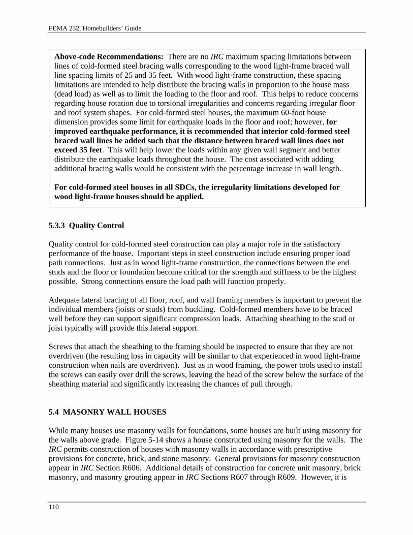
Above-code Recommendations: There are no IRC maximum spacing limitations between lines of cold-formed steel bracing walls corresponding to the wood light-frame braced wall line spacing limits of 25 and 35 feet. With wood light-frame construction, these spacing limitations are intended to help distribute the bracing walls in proportion to the house mass (dead load) as well as to limit the loading to the floor and roof. This helps to reduce concerns regarding house rotation due to torsional irregularities and concerns regarding irregular floor and roof system shapes. For cold-formed steel houses, the maximum 60-foot house dimension provides some limit for earthquake loads in the floor and roof; however, for improved earthquake performance, it is recommended that interior cold-formed steel braced wall lines be added such that the distance between braced wall lines does not exceed 35 feet. This will help lower the loads within any given wall segment and better distribute the earthquake loads throughout the house. The cost associated with adding additional bracing walls would be consistent with the percentage increase in wall length.
For cold-formed steel houses in all SDCs, the irregularity limitations developed for wood light-frame houses should be applied.
5.3.3 Quality Control
Quality control for cold-formed steel construction can play a major role in the satisfactory performance of the house. Important steps in steel construction include ensuring proper load path connections. Just as in wood light-frame construction, the connections between the end studs and the floor or foundation become critical for the strength and stiffness to be the highest possible. Strong connections ensure the load path will function properly.
Adequate lateral bracing of all floor, roof, and wall framing members is important to prevent the individual members (joists or studs) from buckling. Cold-formed members have to be braced well before they can support significant compression loads. Attaching sheathing to the stud or joist typically will provide this lateral support.
Screws that attach the sheathing to the framing should be inspected to ensure that they are not overdriven (the resulting loss in capacity will be similar to that experienced in wood light-frame construction when nails are overdriven). Just as in wood framing, the power tools used to install the screws can easily over drill the screws, leaving the head of the screw below the surface of the sheathing material and significantly increasing the chances of pull through.
5.4 MASONRY WALL HOUSES
While many houses use masonry walls for foundations, some houses are built using masonry for the walls above grade. Figure 5-14 shows a house constructed using masonry for the walls. The IRC permits construction of houses with masonry walls in accordance with prescriptive provisions for concrete, brick, and stone masonry. General provisions for masonry construction appear in IRC Section R606. Additional details of construction for concrete unit masonry, brick masonry, and masonry grouting appear in IRC Sections R607 through R609. However, it is
110

Chapter 5, Walls
important that all masonry cells with reinforcement be grouted, and care should be taken to ensure that the grout is consolidated. Discussed below are the general principles of earthquake-resistant design for masonry wall houses, specific IRC requirements important to earthquake performance, and above-code measures for improved earthquake performance.
Figure 5-14 House constructed with masonry walls.
Masonry wall construction is significantly heavier than light-frame wall construction; however, in most respects, the same principles of earthquake-resistant construction apply. The system resisting wind and earthquake loads most commonly consists of floor and roof assemblies acting as horizontal beams carrying loads to bracing walls. Masonry bracing walls carry wind and earthquake loads down to the foundation with masonry walls primarily resisting loads acting in their strong direction – that is, parallel to the wall. Because masonry walls are heavier than stud framing, it follows that the earthquake loads resisted by each wall element and connection will be greater. As a result, the design of the connections is as important as the proportioning of the floor and roof systems and bracing walls. Significant earthquake loads also develop perpendicular to the wall surface due to the wall’s weight. These loads tend to pull the walls away or push them toward the floor or roof, making wall to floor or roof anchorage critical. Damage from insufficient anchorage or connectivity similar to that shown in Figure 5-12 can result if these connections are not strong enough.
5.4.1 Scope Limitations
One of the primary approaches the IRC uses to deal with the increased earthquake loading associated with masonry wall houses is to limit the scope of houses permitted under the prescriptive provisions. IRC Section R301.2.2 introduces earthquake provisions applicable to houses in SDCs D1 and D2. The first scope limitation is found in IRC Section R301.2.2.2.1, Weights of Materials, which limits masonry walls to 8 inches thick and 80 pounds per square foot, which essentially prohibits the use of rubble stone masonry (IRC Section R606.2.2) as well as relatively thick concrete or brick masonry walls. IRC Section R301.2.2.4.3 triggers the reinforcement and configuration requirements of IRC Section R606.11.3 for all houses in SDC D1 and of Section R606.11.4 for all houses in SDC D2. In SDCs D1 and D2, the scope of
111

FEMA 232, Homebuilders’ Guide
prescriptive construction of houses with masonry walls is effectively limited to walls one story in height with up to 9 feet between lateral supports; beyond this, engineered design is required. A final scope limitation in IRC Section R301.3, Item 3, limits masonry house walls to a clear height of 12 feet with a maximum floor framing depth of 16 inches. An additional 8 feet of masonry wall height is permitted for gable end walls. It is also worth noting that IRC Section R301.2.2.2.2, Item 7, prohibits the mixing of light-frame and masonry construction such that light-frame walls would be required to support earthquake loads due to masonry wall construction (e.g., mixing masonry and light-frame walls on the same story.)
5.4.2 Wall Lateral Support, Reinforcing, and Anchorage
General requirements for lateral support of masonry walls for all SDCs are provided in IRC Section R606.8. Walls are permitted to be laterally supported by cross-walls, pilasters, buttresses, or structural frame members where walls span horizontally between supports and by floors and roofs where walls span vertically between supports. Minimum reinforcing requirements apply only for masonry laid in stack rather than running bond and for interior non-load bearing walls where they intersect with other masonry walls. IRC Section R606.10 requires anchorage of masonry walls to floor and roof systems in accordance with specific details. However, in recent U.S. earthquakes, similar details have been observed to be susceptible to damage. Performance of some of these details for supporting site-built masonry walls also is thought to be problematic. Several details on how to comply with the IRC provisions are provided in the code itself.
IRC Section R606.11.1.1 triggers additional requirements for floor and roof systems for houses in SDCs D1 and D2. Floor and roof wood structural panel sheathing is required to have all edges blocked and nailed at 6 inches on center. Where the floor or roof system is long and narrow (more than twice as long as it is wide), the nailing at sheathing edges is required to be reduced from 6 to 4 inches on center.
For houses in SDC D1, IRC Section R606.11.3 places further limits on masonry walls using prescriptive provisions:
• Masonry walls are limited to one-story, • Additional reinforcing is required, • Reinforcement detailing provisions for masonry columns apply, and • Type N mortar and masonry cement are prohibited.
Similar additional requirements are triggered by IRC Section R606.11.4 for SDC D2. SDCs D1 and D2 requirements are illustrated in IRC Figure R606.10(3). Again, specific design is required for wall to framing anchorage per IRC Section R606.11.2.2.1; thus, the anchorage to roof framing illustrated in IRC Figure R606.10(3) may not be the only alternative.
In the design of wall anchorage to the floor and roof, it is important that a direct tension tie be provided from the wall to the floor or roof framing members if framing is perpendicular or to blocking that is continued across the floor or roof if framing is parallel. Detailing in IRC Figures
112

Chapter 5, Walls
611.8(1) to (7) shows the concept of this connection when used with concrete walls, but they are equally applicable to masonry construction.
5.4.3 Parapet walls
IRC Section R606.2.4 limits masonry thickness and height of parapets in all SDCs and sets the requirements for reinforcing walls of houses in SDCs D1 and D2. Parapet walls are easily damaged in an earthquake and attention to placement of reinforcement and bracing to stabilize the parapet is important.
5.4.4 Problematic Gaps Between Prescriptive and Engineered Construction
The current IRC requirements for masonry construction reveal significant gaps between prescriptive and engineered construction, creating a significant opportunity to employ above-code measures to improve performance.
For areas of high earthquake risk, one notable omission is the lack of a limit on the amount of opening in masonry walls. Light-frame provisions require a percentage of the wall to be solid to provide bracing so that the bracing wall strength is in proportion to the earthquake load, but the same requirement is not imposed for masonry walls. This is of particular concern when the house layout results in front and back walls with a large percentage of openings for doors and windows.
Above-code Recommendation: Each exterior wall and each interior bracing wall should have at least one, and preferably two, sections of solid wall not less than 4 feet in length. Further, sections of solid wall should not be spaced more than 40 feet on center and should be placed as symmetrically as possible (Figure 5-15). The provisions of IRC Section R611.7.4 for ICF walls illustrate a reasonable approach to regulation of minimum wall length. The improvement requires only reasonable planning and should not result in higher construction costs.
IRC Section R403.1 requires that exterior walls be supported on continuous concrete or masonry footings and regulates minimum footing width and depth, but nothing in the IRC appears to require that other masonry walls be supported on foundations.
Above-code Recommendation: It is vital that all masonry walls be supported on substantial continuous footings extended to a depth that provides competent bearing. If this is not done the walls have a high probability of being damaged due to uneven settlement.
There are no IRC maximum spacing limitations between lines of masonry bracing walls corresponding to the light-frame limits of 25 and 35 feet. In light-frame construction, these spacing limitations are intended to help distribute the bracing walls in proportion to the house mass (dead load) as well as to limit the loading to the floor and roof, which helps prevent damage to the house from rotation due to torsional irregularities caused by irregular floor and roof system shapes.
113

FEMA 232, Homebuilders’ Guide
Figure 5-15 Symmetric layout of walls to distribute loads uniformly and thereby prevent torsion.
Above-code Recommendations: Because prescriptive detailing is not available for the addition of interior masonry braced wall lines, it is recommended that the distribution of bracing walls be carefully balanced and that the floor and roof plans use simple rectangular shapes without indentions, bump-outs, or openings. The cost associated with this improvement is proportional to the length of wall added in relation to the initial total wall length.
The IRC also does not regulate house irregularities for masonry construction. The concepts behind IRC Section R301.2.2.2.2, Irregularities 1 through 6, should apply equally to a masonry wall house. The exceptions to Irregularities 2 and 5 also can be applied; however, the rest of the exceptions are not applicable.
Above-code Recommendation: Solid portions of wall should be stacked from floor to floor and masonry walls should be continuous from the top of the structure to the foundation. Masonry walls not directly supported on walls below require engineered design for gravity load support. Design for earthquake and wind loads also should be provided. The cost of this improvement is negligible; it requires only proper planning when laying out the wall positions for the house.
114

Chapter 5, Walls
Above-code Recommendation: Running bond lay up of masonry units is inherently much stronger than a stack bond lay up. For concrete masonry, use of open end units at locations of vertical reinforcement and use of bond beam units for horizontal reinforcement also help to increase the interlocking of the masonry construction, thereby increasing strength. The cost associated with using running bond rather than stacked bond masonry is minimal. The cost of bond beam masonry units for placing horizontal reinforcement at the top of each wall segment would be significantly less than 1 percent of the cost of the original structural system but would dramatically improve the performance of the wall and connection to the floor or roof framing.
Above-code Recommendation: Any of the many required or recommended measures for areas of high earthquake risk would improve the performance of masonry wall houses in areas of lower earthquake risk as well as in high-wind areas. Priorities include provision for reinforcing such as that shown in IRC Figure R606.10(2), wall anchorage using details developed to resist out-of-plane wall loads such as those shown in IRC Figures R611.8(1) to (7) for walls, minimum length of bracing walls, and a maximum spacing of bracing wall lines.
5.4.5 Quality Control
Quality control during masonry construction can play a major role in the satisfactory performance of the masonry. The following should be monitored:
• Proper placement of reinforcing in masonry. Unless specifically designed otherwise, reinforcing should be located as near the centerline of the masonry cavity as possible. In no case should reinforcing be closer than 5/8 inch to a masonry unit wall.
• Anchor bolts should be secured into place before grout placement (not placed into grout following the pour).
• Excess mortar and other obstructions should be cleaned from the cavity to allow free placement of grout.
• Consolidation of the grout after it is placed into the cavity is necessary to eliminate voids.
5.5 INSULATING CONCRETE FORM (ICF) WALL HOUSES
The IRC permits construction of houses with concrete walls in accordance with the prescriptive provisions of IRC Section R611 for ICF (insulating concrete form) walls and Section R612 for conventionally formed walls. ICF walls are concrete that is cast into forms that remain in place to serve as house insulation. The code covers three geometries of ICF forms: flat, waffle-grid, and screen grid forms. Both the waffle and screen grid consist of concrete cast into a series of interconnected horizontal and vertical cores within the insulation. Interior and exterior wall
115

FEMA 232, Homebuilders’ Guide
finishes are applied over the ICF wall form. ICF walls may be used for the full height of the house or for the lower story only with light-frame walls above. The provisions of IRC Section R611 are based on the use of light-frame floor, roof, and ceiling assemblies in ICF wall houses. The light-frame construction can be either wood or steel light-frame; however, current detailing developed for areas of high earthquake demand provides solutions for wood light-frame floors and roofs. This section discusses general principles of earthquake-resistant design for ICF wall houses, specific IRC requirements important to earthquake performance, and above-code measures for improved earthquake performance. An example of ICF construction is shown in Figure 5-16.
Figure 5-16 Insulated concrete form house under construction.
ICF wall construction, like masonry, is significantly heavier than light-frame wall construction. In most respects, however, the same principles of earthquake-resistant construction apply. The system resisting wind and earthquake loads consists of floor and roof assemblies acting as horizontal beams carrying loads to bracing walls. ICF bracing walls carry wind and earthquake loads down to the foundation with ICF walls primarily resisting loads acting in their strong direction, parallel to the wall (shear walls). Because ICF walls are heavier than light-frame walls, the earthquake loads to be resisted by each wall element and connection will be greater. As a result, proportioning of the floor and roof systems and bracing walls is important as are the connections between the walls and the floor and roof framing. Significant earthquake loads also develop perpendicular to the wall surface due to the wall weight. These loads tend to pull the walls away or push them toward the floor or roof, making wall to floor and wall to roof anchorage very important.
5.5.1 Scope Limitations
One of the primary approaches the IRC uses to address the increased earthquake loading with ICF wall houses is to limit the scope of houses permitted under the prescriptive provisions. For ICF, some scope limitations are found in Chapter 3 while others are found in IRC Section R611. For all Seismic Design Categories, ICF wall houses are limited to two stories above grade. The maximum permitted house plan dimension is 60 feet, and framing clear spans are limited to 32 feet for floors and 40 feet for roofs (IRC Section R611.2). For houses in SDCs D1 and D2, IRC Section R301.2.2.2.1 limits the dead weight of concrete walls to 85 pounds per square foot for walls that are 6 inches of solid concrete. IRC Section R611.7.4 limits the minimum nominal thickness of the wall to 5-1/2 inches. Application of these criteria and the maximum unit weights in IRC Table R611.2 permits use of 5-1/2-inch flat ICF walls, 6- and 8-inch waffle-grid
116

Chapter 5, Walls
walls, and 6-inch screen grid walls. The weight of interior and exterior wall finishes is limited to 8 psf (IRC Section R611.2). Floor and roof plus ceiling assembly weights also are limited by IRC Section R301.2.2.2.1 as for the other materials.
For houses in SDCs D1 and D2, IRC Section 611.2 limits the scope to rectangular houses with a maximum floor and roof aspect ratio (length to width ratio) of 2:1 and requires that the ICF walls be aligned vertically (stacked) without cantilevers or setbacks. An additional limitation is that the gable end portion of walls must be of light-frame rather than ICF construction. Further, the top of the ICF wall must be anchored to a required attic floor as described in IRC Section R611.9.
For houses in SDCs D1 and D2, IRC Section R301.2.2.2.2 requires engineered design for irregular portions of houses. The irregularities are discussed in detail in an earlier section of this guide. The exceptions to irregularities are mostly applicable to wood-frame construction and so do not apply. The 2003 IRC as printed refers to irregularities in IRC Sections R301.2.2.7 and R301.2.2.9, which do not exist; the intent was to reference IRC Section R301.2.2.2. IRC Section R611.8.3.1 repeats the prohibition of vertical offsets in floor framing (such as split levels) in SDCs D1 and D2.
IRC Section R301.2.2.4.4 triggers the requirements of IRC Sections R611 and R612 for all houses in SDCs D1 and D2. These requirements include all of the reinforcement and detailing provisions for concrete walls that provide the continuity and connectivity for the system to function effectively under wind or earthquake loads.
5.5.2 Wall Reinforcing and Anchorage
Reinforcing steel is of primary importance for concrete and masonry house performance. The reinforcing steel is what ties the components together and provides toughness to the concrete when it cracks. General requirements for reinforcing of ICF walls are provided in IRC Sections R611.3 through R611.5. Reinforcing is required for all ICF walls across all SDCs. IRC Section R611.7.1.2 imposes additional minimum reinforcing size and spacing limits for houses in SDCs D1 and D2. IRC Section R611.7.1.3 provides similar limits for horizontal reinforcing and includes requirements to provide for continuity of reinforcing around house corners and termination of horizontal reinforcement. Reinforcement is required to be doweled into the foundation and extend for the full height of the ICF wall, including the parapet if applicable. Lap splicing of reinforcing is permitted.
Like light-frame wall bracing provisions, ICF wall provisions require a minimum length or percentage of the wall to be solid (without openings) so that the bracing wall strength is in proportion to the earthquake load. The minimum required lengths of bracing wall for ICF construction in each Seismic Design Category are defined in IRC Section R611.7.4. Minimum bracing lengths must be provided for wind load parallel and perpendicular to the ridge per IRC Tables 611.7(9A) through (10B). The required bracing length must be provided using wall segments not less than 2 feet in width. For all houses in SDCs D1 and D2, the bracing length requirements of IRC Table R611.7(11) also must be met using wall segments that are not less
117

FEMA 232, Homebuilders’ Guide
than 4 feet in width. The increase from 2 to 4 feet provides a wall that is stronger and much better able to withstand cyclic earthquake loading.
Also of primary importance for house performance is the connection of the ICF walls to the floors and roofs, both for bracing loads parallel to the wall and out-of-plane loads perpendicular to the wall. The IRC addresses three types of connections to wood light-frame floors and roofs:
• Top bearing connections where the light-frame floor bears on the top of the ICF wall with light-frame walls above (IRC Section R611.8.1),
• Ledger-bearing connections where the floor or roof is supported off the face of the ICF wall by a wood ledger (IRC Section R611.8.2), and
• Top-bearing connections where the light-frame roof bears on top of the ICF wall (IRC Section R611.9).
It is important that a direct tension tie be provided from the wall to the floor or roof framing or blocking to resist loads perpendicular to the wall (this connection keeps the wall from pulling away from the floor or roof framing). This does not necessarily occur for lower Seismic Design Categories. For top bearing connections, sill plate to framing connections rely on minimum prescriptive fastening at framing perpendicular to the wall and no provision exists for a tension connection at framing parallel to the wall. For ledger-bearing connections, the direct tension ties shown in IRC Figures R611.8(2) through R611.8(5) are not required for lower SDCs, leaving the remaining ledger connection susceptible to cross-grain tension failure as illustrated in Figure 5-17. Very specific prescriptive anchorage requirements capable of resisting perpendicular-to-wall loads are given for sill or ledger to wood framing connections for houses in SDCs D1 and D2. Included are angle clips from sill to joist or blocking, continuous straps tying blocking together, and direct tension ties at ledger-bearing connections. Detailing is illustrated in IRC Figures R611.8(1) to 611.8(7) and R611.9. The specification of a maximum bolt size of 3/8-inch diameter for top-bearing connections is intended to favor bending of the bolt as a failure method over a brittle failure of the concrete or splitting of the wood. Larger bolt sizes should not be substituted.
Figure 5-17 Illustration of cross-grain bending of wood ledger.
118

Chapter 5, Walls
IRC Section R611.8.3 addresses requirements for floor and roof systems. The floor and roof systems act as horizontal beams carrying wind and earthquake loads to the bracing walls. The increased weight of the ICF walls results in increased earthquake load in the floor and roof systems. For SDCs A through C, use of wood structural panel sheathing is required, and the IRC minimum fastening schedules of 6 inches around the perimeter of each sheet and 12 inches along intermediate supports are referenced. IRC Section R611.8.3.1 triggers additional requirements for houses in SDCs D1 and D2. Minimum panel thicknesses are specified for floor and roof wood structural panel sheathing, minimum nail diameter and penetration are specified, all panel edges are required to be blocked, and the panel edge nailing is required to be 4 inches on center in SDC D1 and 3 inches on center in SDC D2.
IRC Section R611.9.1 has similar requirements for roof construction but also contains two notable variations. First, the requirements apply to houses in SDCs D1 and D2. Second, where gable end wall conditions occur, it is required that a wood structural panel sheathed attic be provided to support the gable end wall (for truss roofs, the wood structural panel sheathing can be applied to the bottom of the truss between the truss chord and the ceiling finish material) and that the wall be anchored in accordance with requirements for anchorage to floor and roof diaphragms. IRC Section R611.2 requires that the gable-end portion of this wall be light-framed. The writers of the ICF provisions preferred this solution over allowing increased ICF wall heights at the gable end due to the increased loads associated with concrete and the additional bracing requirements.
IRC Section R403.1 requires that exterior walls be supported on continuous concrete or masonry footings and regulates minimum footing width and depth. If interior ICF walls are provided, these too should be supported on substantial continuous footings extended to a depth that provides competent bearing.
5.5.3 Problematic Gaps Between Prescriptive and Engineered Construction
The current IRC requirements for ICF wall construction reveal some gaps between prescriptive and engineered construction creating an opportunity for above-code measures to improve performance in areas of high earthquake risk.
There are no IRC maximum spacing limitations between lines of ICF bracing walls corresponding to the light-frame limits of 25 and 35 feet. In light-frame construction, these spacing limitations are intended to help distribute the bracing walls in proportion to the house mass (dead load) as well as to limit the loading to the floor and roof. This helps to reduce concerns regarding house rotation due to torsional irregularities and concerns regarding irregular floor and roof system shapes. For ICF wall houses, the scope limitation to rectangular houses reduces the likelihood of rotational behavior.
Above-code Recommendation: Careful balancing of bracing walls around the house perimeter is recommended to further limit torsional behavior. The maximum 60-foot house dimension will provide some limit for earthquake loads in the floor and roof. The cost of distributing the wall segments around the perimeter of the house should not result in any increased cost for construction.
119

FEMA 232, Homebuilders’ Guide
For ICF wall houses, some of the irregularity limitations developed for light-frame houses have been made applicable. The concepts behind IRC Section 301.2.2.2.2, Irregularities 1 through 6, apply equally to an ICF wall house.
Above-code Recommendation: Any of the many required or recommended measures for areas of high earthquake risk would improve performance of ICF wall houses in areas of lower earthquake risk as well as in high-wind areas. Most of the recommendations would improve house performance in high-wind events. Priorities include wall anchorage using details developed to resist out-of-plane wall loads such as those shown in IRC Figures R611.8(2) to R611.8(7).
5.5.4 Quality Control
Quality control for ICF wall construction can play a major role in the satisfactory performance of the house. Important steps in ICF construction include:
• Reinforcing should be placed properly. Unless specifically designed otherwise, reinforcing should be located as near the centerline of the ICF cavity as possible but at least within the middle third of the wall.
• Anchor bolts should be secured into place before concrete placement (not placed into concrete following placement of the concrete) to prevent air pockets from forming around the bolt which reduces its strength.
• Concrete should be consolidated as it is placed into the forms to prevent voids from forming.
120

Chapter 6 ROOF-CEILING SYSTEMS
Woodframe roof-ceiling systems are the focus of this chapter. Cold-formed steel framing for a roof-ceiling system also is permitted by the IRC but will not be discussed; rather, the reader is referred to the AISI Standard for Cold-Formed Steel Framing – Prescriptive Method for One- and Two-Family Dwellings (2001) for guidance. Most of the recommendations for improving the earthquake performance of woodframe roof-ceiling systems also apply to cold-formed steel construction since the systems are very similar.
6.1 GENERAL ROOF-CEILING REQUIREMENTS
Woodframe roof-ceiling systems, regardless of the pitch of the roof, form a roof diaphragm that transfers earthquake lateral loads to braced walls in the story level immediately below the roof in the same manner that floors transfer loads from interior portions of the floor to the braced wall lines of the story below. The lateral loads in the roof-ceiling are based on the mass of the roof-ceiling assembly and a portion of the mass of the walls in the story immediately below the roof.
Woodframe roof-ceilings typically consist of repetitive rafters and ceiling joists or prefabricated (engineered) trusses at a prescribed spacing. They are sheathed with either spaced solid wood boards or with wood structural panels attached to the top surface of the rafter or truss. Figure 6-1 illustrates this type of roof and ceiling framing system. Roof members also can consist of repetitive beams spaced further apart than rafters, either with or without ceiling joists.
Figure 6-1 Typical light-frame roof-ceiling system.
121

FEMA 232, Homebuilders’ Guide
Depending on the roof shape chosen for a house, hip and valley beam members may be needed where intersecting rafters change the direction of their span. Depending on the slope of the roof, hip and valley rafters can experience very high loads when supporting long-span rafters. Therefore, purlins are sometimes provided below and perpendicular to rafters. The purlins, in turn, are supported by a stud or post attached to a wall or beam below. Ridge boards also are often provided at the peak of a roof where sloping rafters meet. Blocking between rafters (or trusses) is used at the bearing points of rafters and ceiling joists to prevent lateral movement or rolling of the rafter. Finish materials such as gypsum board are typically applied to the bottom surface of ceiling joists or the bottom chord of a truss if the space below is to be occupied.
Rafters, purlins, ridge boards, and hip or valley members can be sawn lumber, end-jointed lumber, or any one of a variety of prefabricated (engineered) members. Examples of engineered lumber include wood I-joists or solid rectangular structural composite members such as parallel strand lumber (PSL), laminated veneer lumber (LVL), or laminated strand lumber (LSL). Roof beams and blocking can be either sawn lumber or engineered lumber.
The minimum required size and maximum span and spacing of roof rafters or beams, ceiling joists, and trusses is based on providing adequate support for dead and live vertical loads prescribed by the code. Snow loads must be considered for rafters, and attic storage must be taken into account for ceiling joists. Vertical deflection of rafters and ceiling joists is another design consideration that may limit the maximum span of these members. Rafter spans listed in prescriptive tables are based on the horizontal projection of the rafter rather than being measured along the slope, which would be a greater distance.
Tables in IRC Chapter 8 and similar tables in other documents such as those published by the American Forest and Paper Association (AF&PA) or engineered lumber manufacturers are available for use in selecting the proper combination of size, span, and spacing of most roof-ceiling framing members. Depending on the roof pitch, certain roof members require engineering to determine their size. For a roof pitch less than 3:12, the size of ridge boards and hip or valley members must be individually determined based on their spans and the span of the rafters they support.
6.2 SPECIAL FRAMING CONSIDERATIONS
Roof rafters must either be tied together at the ridge by a gusset plate or be framed to a ridge board. Ridge boards in roofs having a pitch of 3:12 or greater must be at least 1x nominal thickness and at least the same depth as the cut end of the intersecting rafters. Valley and hip members in a roof having a pitch of 3:12 or greater must be at least 2x nominal thickness and at least the same depth as the cut end of the rafters. Because the cut end depth of a rafter increases with increasing roof pitch, a 2x8 rafter will need a 1x10 nominal ridge board and a 2x10 nominal hip or valley member for a pitch up to 9:12. At a pitch exceeding 9:12, a 1x12 or 2x12 will be needed because the cut end of a 2x8 rafter will be greater than the 9-1/4 inch actual depth of a 1x10 or 2x10 nominal member. Figure 6-2 shows a 1x12 ridge board for a 12:12 pitch condition with the dimension for the cut end of a 2x8 rafter.
122

Chapter 6, Roof-Ceiling Systems
Figure 6-2 Ridge board for 12:12 pitch roof.
One additional consideration when using nominal 1x ridge boards is that ceiling joists or rafter ties are needed at the top plate of the supporting walls to prevent the walls from spreading outward. The ceiling joists or rafter ties act as a brace to resist the outward thrust of the rafters at the wall support ends of rafters. In the absence of ceiling joists or ties at the wall top plate, rafters must be supported at the ridge by a beam designed for the support of rafter loads. In addition, where a nominal 1x ridge is used and a 2x valley or hip member intersects the ridge, the valley or hip member must be supported by a stud or post attached to a bearing wall below to transfer the high loads associated with hip and valley rafters.
Above-code Recommendations: A special condition can occur at the gable ends of a roof. When the exterior wall at the gable end has its double top plate level with the low ends of the roof framing, the wall studs are not continuous to the roof sheathing along the gable edge. A section view of this condition is shown in Figure 6-3. To provide above-code performance, the framing extending above the top plate to the level of the sloping gable end roof sheathing should be braced at regular intervals of not more than 4 feet on center at both the wall top plate level and along the top edge of the sloping roof edge. This bracing permits the top of the exterior wall and the framing extending above to resist the lateral loads that are acting perpendicular to the wall. Without this bracing, the framing above the double top plate could be easily displaced because a hinge can form where the gable end wall framing attaches to the top plate.
Another above-code alternative to the framing shown in Figure 6-3 would be to provide wall studs that are continuous to a sloping double top plate located just below the roof sheathing (balloon framing). When continuous studs are provided, there is no weak location for a hinge to form. However, when this method is used, the required stud size, spacing, and maximum height must comply with IRC Table R602.3.1 or the wall studs will need to be engineered by a design professional. Bracing a gable end wall also is important for providing resistance to high winds, especially for roofs with a steep pitch.
123

FEMA 232, Homebuilders’ Guide
Figure 6-3 Gable end wall or gable truss bracing.
6.3 BLOCKING AND LATERAL LOAD PATHS FOR ROOF SYSTEMS
Rafters and ceiling joists having a nominal depth-to-thickness ratio exceeding 5:1 (e.g., 2x10) need blocking at their points of bearing to prevent them from rotating or displacing laterally from their intended position. Rotation loads on rafters occur when the roof sheathing is resisting lateral loads perpendicular to the rafter because these loads are actually trying to move the top edge of the rafter sideways. Preventing rotation is typically accomplished by installing full-depth solid blocking along wall top plates between rafters and ceiling joists. Figure 6-4 illustrates blocking installed between adjacent pairs of a ceiling joist and rafter that are bearing on an exterior wall.
124
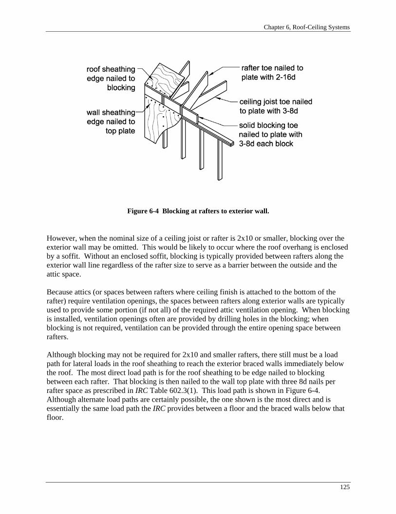
Chapter 6, Roof-Ceiling Systems
Figure 6-4 Blocking at rafters to exterior wall.
However, when the nominal size of a ceiling joist or rafter is 2x10 or smaller, blocking over the exterior wall may be omitted. This would be likely to occur where the roof overhang is enclosed by a soffit. Without an enclosed soffit, blocking is typically provided between rafters along the exterior wall line regardless of the rafter size to serve as a barrier between the outside and the attic space.
Because attics (or spaces between rafters where ceiling finish is attached to the bottom of the rafter) require ventilation openings, the spaces between rafters along exterior walls are typically used to provide some portion (if not all) of the required attic ventilation opening. When blocking is installed, ventilation openings often are provided by drilling holes in the blocking; when blocking is not required, ventilation can be provided through the entire opening space between rafters.
Although blocking may not be required for 2x10 and smaller rafters, there still must be a load path for lateral loads in the roof sheathing to reach the exterior braced walls immediately below the roof. The most direct load path is for the roof sheathing to be edge nailed to blocking between each rafter. That blocking is then nailed to the wall top plate with three 8d nails per rafter space as prescribed in IRC Table 602.3(1). This load path is shown in Figure 6-4. Although alternate load paths are certainly possible, the one shown is the most direct and is essentially the same load path the IRC provides between a floor and the braced walls below that floor.
125

FEMA 232, Homebuilders’ Guide
Above-code Recommendation: In Seismic Design Categories D1 and D2, blocking is recommended between rafters along exterior wall lines to provide a surface for the edge nailing of roof sheathing and to provide a very direct load path to the top plate of the exterior braced walls. When this blocking is provided, it also is necessary to ensure that minimum attic ventilation opening requirements are met. Depending on the attic area being ventilated, this can be accomplished by drilling holes in the blocking and, when more opening area is necessary, by adding gable end wall openings or ridge vents.
6.4 CONNECTION OF CEILING JOISTS AND RAFTERS TO WALLS BELOW
Ceiling joists and rafters (or trusses) are required to be connected to the top plate of supporting walls as specified in IRC Table R602.3(1). These connections also provide a portion of the load path that transfers loads from the roof diaphragm into the braced walls below. Ceiling joists require a toe-nailed connection to the top plate using three 8d box or common nails. Rafters also require a toe-nailed connection to the top plate using two 16d box or common nails. Blocking installed between the rafters or ceiling joists requires a toe-nailed connection to the top plate using a minimum of three 8d box or common nails in each block. Toe nailing must be done correctly if the needed transfer of loads is to occur; therefore, ensure that the nails do not split the wood. In high-wind areas, light-gage steel connectors often are used in place of these toe-nailed connections. The use of commercially available light gage steel connectors in place of toe nails can reduce wood splitting and provide more reliable load transfer. Additional information on proper toe-nailing installation is illustrated in Figure 4-8.
6.5 ROOF SHEATHING
Wood boards installed either perpendicular or at an angle to the rafters (or trusses) or wood structural panels can be used as roof sheathing. IRC Table R803.1 specifies the minimum thickness for wood board roof sheathing for various spacings between roof rafters, trusses, or beams.
Above-code Recommendation: Solid wood board roof sheathing is rarely used in modern housing construction except perhaps along roof eave overhangs. When wood boards are used and are installed perpendicular to rafters they provide a very weak diaphragm with little stiffness. As a result, solid wood board sheathing installed perpendicular to rafters should not be used in Seismic Design Categories C, D1, and D2. Wood boards installed diagonally would provide much better diaphragm capacity but are very rarely used in modern housing construction.
Wood structural panel roof sheathing is the most common roof sheathing used in current construction. The minimum thickness is based on rafter (or truss) spacing and the grade of sheathing panels selected. IRC Table R503.2.1.1(1) is used to determine the minimum required thickness for wood structural panel roof sheathing materials for a variety of rafter spacings. For roofs, the short direction panel joints between wood structural panels can be either staggered or
126

Chapter 6, Roof-Ceiling Systems
not staggered. Typical wood structural panel roof sheathing installation using staggered joints is illustrated in Figure 6-5.
Figure 6-5 Typical roof diaphragm sheathing nailing when wood structural panels are used.
When the roof covering consists of wood shingles or shakes, IRC Chapter 9 permits the use of spaced wood boards as roof sheathing. However, spaced wood board sheathing is not permitted in Seismic Design Category D2. This limitation in SDC D2 is intended to provide a stiffer and stronger roof diaphragm that will resist the larger lateral loads anticipated in SDC D2. When wood boards are used, they typically are nailed to each rafter with only two 8d box or common nails. Wood structural panel sheathing results in the stiffest roof diaphragms, and the panels typically are fastened to the rafters with 8d box or common nails spaced at 6 inches along supported edges and 12 inches in the field of the panel. When spaced wood boards are used, even fewer nails are provided than with solid wood board sheathing and even less lateral resistance results.
Above-code Recommendation: Spaced wood board sheathing is not recommended for use in Seismic Design Categories C and D1.
127

FEMA 232, Homebuilders’ Guide
6.6 LATERAL CAPACITY ISSUES FOR WOOD FRAMED ROOFS
The lateral capacity of a roof diaphragm sheathed with wood structural panels is based upon the same five factors as floor diaphragms. (See the discussion in Section 4.7 of this guide for more information on the effects of sheathing thickness, fastener size and spacing, use of blocking, and layout of wood structural panel sheathing.)
The effects of distance between braced wall lines below the roof and the effects of large roof openings (e.g., skylights) are also similar to those discussed for floors. The recommendations for reinforcing floor diaphragms with large openings also apply when roof openings exceed the code maximum limits. (See Section 4-7 for more information.)
Although roof-ceiling systems typically are subjected to the smallest loads when a house experiences earthquake ground motion, several simple things can be done to improve the performance of the system.
Above-code Recommendations:
Reinforce the framing around skylights to provide positive connections to transfer the diaphragm loads around the opening. Strapping and blocking as illustrated in Figure 4-11 can be used to strengthen the roof around large openings and the additional cost for the blocking and strapping for a typical skylight opening would add less than 0.4 percent to the cost of the structural portion of the project.
Make sure all rafters and ceiling joists are blocked at all locations where they are in contact with a top plate of a wall below (alternately a rim joist may be used). For the exterior walls of the model house, this would cost 0.8 percent of the structural portion of the project. If interior walls were also blocked, an additional cost of 0.7 percent of the structural portion of the project would be incurred.
Glue the sheathing to the roof framing in the same way most floor sheathing is installed and then block the roof as well. Construction adhesives are typically used to prevent squeaky floors but they also strengthen and stiffen. The cost of adding adhesive to the roof system for the model house in this guide would be 1.8 percent of the structural system, and adding blocking to the roof system would add another 3.4 percent to the cost of the structural system.
128

Chapter 6, Roof-Ceiling Systems
6.7 QUALITY CONTROL
The most important item to monitor for quality of the roof diaphragm system is to ensure that the nails used to attach the sheathing to the framing are driven flush with the top of the sheathing and not overdriven and counter sunk into the sheathing materials. Overdriving sheathing nails has been shown to reduce the strength of shear walls and diaphragms. Evidence of a 40 to 60 percent loss in strength of the shear wall and diaphragm has been observed in laboratory tests of assemblies with overdriven nails. (See Section 5.1.4 of this Guide for more discussion on the effects of overdriven nails and how pneumatic tools can be altered to correct for this error.)
To ensure the quality of the roof-ceiling system, make sure blocking is installed correctly so that the wood framing is not split by the toe nailing.
If adhesives are used to attach the sheathing, attention needs to be paid to the time between the application of the adhesive and when the nails are driven to hold the sheathing in place. Especially in hot weather, the adhesive tends to skin over or cure on the surface quickly, which reduces the adhesion between the glue and the sheathing. Check the time allowed for each specific product used.
129

FEMA 232, Homebuilders’ Guide
130

Chapter 7 CHIMNEYS, FIREPLACES, BALCONIES, AND DECKS
This chapter provides an overview of the IRC provisions for earthquake-resistant design and construction of chimneys, fireplaces, balconies, and decks in houses. Above-code recommendations for improved earthquake performance are provided.
7.1 CHIMNEYS AND FIREPLACES
IRC Chapter 10 presents requirements for masonry fireplaces and chimneys and for factory-built fireplaces and chimneys enclosed in framing. The provisions of the IRC are intended for the moderately sized fireplaces and chimneys commonly found in houses.
Above-code Recommendation: Where fireplaces or chimneys are large or oddly configured, an engineered design is encouraged in order to fully address the design of the chimney and fireplace and their influence on the house.
7.1.1 Masonry Chimneys and Fireplaces
Although the IRC permits construction of masonry fireplaces and chimneys in earthquake-prone regions, masonry chimneys are particularly vulnerable to earthquake damage, and such damage has occurred in most moderate to severe U.S. earthquakes (Figures 7-1 and 7-2). Masonry fireplaces and chimneys can be heavy and rigid, and many chimneys in existing houses also are brittle. The movement of the fireplace and chimney in response to earthquake ground motions can be significantly different from the movement of the light-frame house itself, creating the potential for damage to both the chimney and the house.
Figure 7-1 Chimney damage.Photo Courtesy NationalInformation Service for Earthquake Engineering, University of California, Berkeley
131

FEMA 232, Homebuilders’ Guide
Figure 7-2 Chimney damage in Northridge earthquake.
The IRC triggers requirements for masonry fireplace and chimney reinforcing steel and anchorage to floors, roofs, and ceilings for houses in SDCs D1 and D2. Although these requirements cannot completely eliminate the possibility of damage to the fireplace and chimney in an earthquake, their use permits a chimney to better withstand earthquake loads and should lessen the falling hazard posed by a damaged chimney. Although it may be possible with systematic engineering design to mitigate the damage often seen in masonry chimneys and fireplaces, the lower weight and greater flexibility of factory-built fireplaces and chimneys make them the better choice for light-frame houses in earthquake-prone areas.
A substantial footing is necessary if a fireplace and chimney is to perform well under any type of loading. The footing should extend to a depth not less than that of surrounding footings. IRC Section R1003 contains minimum footing requirements.
IRC Section R1003.3 provides requirements for masonry chimney and fireplace reinforcing steel. The minimum amount of vertical reinforcing steel is four No. 4 bars for a chimney up to 40 inches wide (a depth of approximately 24 inches is common). An additional two No. 4 vertical bars are required for each additional flue or each additional 40 inches of width. Where the reinforcing bars cannot run full height, a lap splice of not less than 24 inches is needed. Grout, continuous from the footing to the top of the chimney, must surround the reinforcing steel. For horizontal reinforcing, a minimum of 1/4-inch ties at not more than 18 inches on center is required in the mortar joints. IRC Section R1003.3 also cites the Section R609 requirements for grouted masonry discussed in Chapter 5 of this guide. Proper grouting and consolidation around the reinforcing steel is needed in order for the reinforcing and anchorage to contribute to earthquake resistance. Lack of grout and poorly consolidated grout are common contributors to earthquake damage. It is also important to note that IRC Section R609 prohibits the use of Type N masonry mortar in SDCs D1 and D2.
132

Chapter 7, Chimneys, Fireplaces, Balconies, and Decks
Anchorage of the masonry chimney to the framing at each above grade floor, roof, and ceiling level is necessary. IRC Section R1003.4 provides anchorage requirements applicable in SDCs D1 and D2. Steel straps not less than 3/16-inch by 1-inch are required to extend a minimum of 12 inches into the chimney masonry, hook around outer reinforcing bars, and extend not less than 6 inches beyond the hook. Chimney anchorage locations are illustrated in Figures 7-3 and 7-4. The IRC provisions specify anchorage to a minimum of four ceiling or roof joists with not less than two 1/2-inch bolts. This description does not give details of the intended configuration and does not address framing parallel to the chimney wall. Figures 7-5 and 7-6 illustrate implementation of this anchorage provision with detailing consistent with industry recommendations (MIA, 1995) and earlier Uniform Building Code provisions. Anchorage in general conformance with Figures 7-5 and 7-6 should be consistent with the intent of the IRC.
Figure 7-3 Locations for earthquake anchorage of masonry chimney at exterior house wall.
133

FEMA 232, Homebuilders’ Guide
Figure 7-4 Chimney section showing earthquake anchorage.
Figure 7-5 Anchorage detail for framing parallel to exterior wall.
134
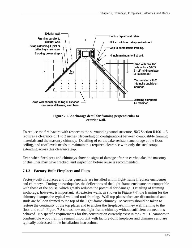
Chapter 7, Chimneys, Fireplaces, Balconies, and Decks
Figure 7-6 Anchorage detail for framing perpendicular to exterior wall.
To reduce the fire hazard with respect to the surrounding wood structure, IRC Section R1001.15 requires a clearance of 1 to 2 inches (depending on configuration) between combustible framing materials and the masonry chimney. Detailing of earthquake-resistant anchorage at the floor, ceiling, and roof levels needs to maintain this required clearance with only the steel straps extending across this clearance gap.
Even when fireplaces and chimneys show no signs of damage after an earthquake, the masonry or flue liner may have cracked, and inspection before reuse is recommended.
7.1.2 Factory-Built Fireplaces and Flues
Factory-built fireplaces and flues generally are installed within light-frame fireplace enclosures and chimneys. During an earthquake, the deflections of the light-frame enclosure are compatible with those of the house, which greatly reduces the potential for damage. Detailing of framing anchorage, however, is important. At exterior walls, as shown in Figure 7-7, the framing for the chimney disrupts the typical wall and roof framing. Wall top plates often are discontinued and studs are balloon framed to the top of the light-frame chimney. Measures should be taken to restore the continuity of the top plates and to anchor the fireplace/chimney wall framing to the floor and roof. Figure 7-8 shows how one light-frame chimney without sufficient connections behaved. No specific requirements for this construction currently exist in the IRC. Clearances to combustible wood framing remain important with factory-built fireplaces and chimneys and are typically addressed in the installation instructions.
135

FEMA 232, Homebuilders’ Guide
Figure 7-8 Collapsed factory-built chimney, light-frame enclosure, and deck after the San Simeon earthquake.
Figure 7-7 Factory-built flue Photo courtesy of Josh Marrow, Simpson Gumpertz and Heger and light-frame enclosure. Inc.
Above-code Recommendations: Factory-built fireplaces and flues typically are installed within light-frame fireplace enclosures and chimneys that generally perform well during earthquakes; therefore, their use in the higher Seismic Design Categories is recommended. However, special attention should be given to the detailing of the framing anchorage and to compliance with clearances to combustible wood framing addressed in installation instructions.
Use of stone or masonry veneer increases the weight of the light-frame chimney, thereby increasing earthquake loads proportionately. Particular care should be taken to tie the wood framing into the floor and roof when veneer is used. Veneer attachment to the framing should be in accordance with IRC Chapter 7. See Section 5.2 of this guide for a discussion of veneer attachment.
Above-code Recommendation: Use of reinforcing steel and chimney anchorage are recommended to improve the performance of fireplaces and chimneys across all Seismic Design Categories and particularly in SDC C. Adding reinforcement and anchorage for the chimney on the model house used in this guide would increase the cost of the structural portion of the house by approximately 2 percent, which is approximately 0.5 percent of the total cost.
136

Chapter 7, Chimneys, Fireplaces, Balconies, and Decks
Above-code Recommendation: Both masonry and factory-built fireplaces and chimneys result in increased weight and earthquake loading as well as discontinuities in house configuration. Additional bracing walls in both directions in the vicinity of the fireplace are recommended to resist the additional earthquake load. This will result in a reduction in the amount of window opening available, but the cost of adding the wall will likely be offset by the reduced cost for windows.
7.2 BALCONIES AND DECKS
Balconies and decks often are prominent features of modern residential construction and, for many people, add much desired living space (see Figure 7-9). Although the IRC contains some provisions addressing balconies and decks, the earthquake resistance of balconies and decks has not been systematically considered in the development of the IRC provisions. This section addresses three aspects of balconies and decks that need consideration:
• The effect of added floor area beyond braced wall lines, • Anchorage for earthquake loads, and • Vertical support.
7.2.1 Added Floor Area Beyond Braced Wall Lines
The bracing provisions of the IRC reflect the need to support the floor area within the exterior braced wall lines. The addition of balconies and decks creates additional weight and increases earthquake loads, a fact that was not envisioned when required bracing lengths were determined. Although the addition of a small balcony or deck is not likely to greatly affect the earthquake performance of a house, the addition of a large balcony or deck may. Further, balconies and decks tend to concentrate the added earthquake load on one side of the house and one braced wall line. This can contribute to rotational behavior (see the discussion of plan irregularities in Section 2.3 of this guide) and concentrations of damage.
Two IRC sections limit balcony and deck size:
• IRC Section R502.3.3 addresses floor framing cantilevers, including exterior balconies. IRC Table R502.3.3(2) specifies permitted cantilevers as a function of framing size and spacing and live load. Permissible cantilevers range up to a maximum of 6 feet (see additional discussion of back-span connections in Section 4.3 of this guide).
• For SDCs D1 and D2, IRC Section R301.2.2.2.2, Item 2, requires braced wall lines on all edges of a floor or roof. The exception to Item 2 permits floors that do not support braced wall panels to extend up to 6 feet beyond a braced wall line.
137

FEMA 232, Homebuilders’ Guide
Figure 7-9 Decks and balconies in residential construction.
Balconies extending more than 6 feet beyond the exterior house wall in all Seismic Design Categories fall outside of the framing provisions of the IRC and require engineered design.
Where balconies or decks extend more that 6 feet beyond the house exterior, additional lines of bracing for earthquake and wind loads are sometimes provided. When this approach is taken, it is important that loading in both the longitudinal and transverse directions be considered. In addition, when both the house and supplemental bracing are used to support the balcony or deck, the load-deformation behavior of the bracing system must be compatible with that of the house. Where this is not the case, it is best to completely separate the balcony or deck from the house and provide a gap large enough to permit independent movement.
138

Chapter 7, Chimneys, Fireplaces, Balconies, and Decks
7.2.2 Anchorage for Earthquake Loads
Where a balcony or deck is laterally supported by the house, adequate connection to the house is key to good earthquake performance. The IRC includes two provisions that address anchorage to the house:
• IRC Section R311.2.1 requires that the connections used to attach exterior balconies, stairs, and similar exit facilities to the rest of the structure provide for resistance to both vertical and lateral loads, but the magnitude of loads to be resisted is not specified. Use of toe nails or nails subject to withdrawal is prohibited.
• IRC Section R502.2.1 provides similar requirements for decks.
Because balcony framing generally has a back span that extends into the interior of the house, adequate connection generally is not an issue; however, care should be taken to ensure that the back span is adequately fastened to the floor sheathing or to lapped floor framing and that blocking is provided where the cantilever bears on the exterior wall.
Above-code Recommendation: Deck framing, on the other hand, does not generally have inherent continuity into the house. Attachment only to the floor band (rim) joist is not sufficient and will result in failures between the band joist and the rest of the floor system. Engineered design of connections is recommended as is use of a positive connection, such as the hold-down device shown in Figure 7-10.
Figure 7-10 Hold-down device providing positive connection of deck framing to house framing.
139
FEMA 232, Homebuilders’ Guide
7.2.3 Vertical Support Issues
Although beyond the scope of earthquake resistance, two issues – vertical load connections and moisture and decay – related to vertical support of decks and balconies are of enough significance to warrant discussion.
Deck construction is notoriously problematic and typically at least one deck collapse occurs somewhere in the United States every week. Inadequate connection between the deck and the house for vertical loads is the biggest problem. Where an engineered design is not provided, connections for vertical loads very often are inadequate. Inadequate connection for lateral loading also can be a contributor. Attention to adequacy of vertical load connections is imperative for safety.
Above code Recommendation: Providing a line of vertical support (posts and beams) alongside the exterior house wall can help to reduce the load on the deck-to-house connection.
The interface between a balcony or deck and the exterior house wall is critical for the waterproofing system. Penetration of moisture at this interface can endanger not only the capacity of the connection but also the interior and exterior framing members. IRC Section R319.1.2 requires that the joints of exterior balconies be designed such that moisture will not collect in the connection area or that the connection be otherwise protected from moisture.
Above-code Recommendation: The joints of exterior decks should be designed such that moisture will not collect in the connection area or that the connection is otherwise protected from moisture.
The resource list provided in Appendix E includes references addressing deck connections and moisture and decay issues.
Above-code Recommendation: As noted, balconies and decks often are subjected to significant lateral loads during an earthquake. As an above-code measure for houses located in SDCs C, D1 and D2, the connections used to attach the deck to the house should be designed by a registered design professional to ensure that the loads acting on the deck are properly transferred to the framing of the house. In addition, the lateral bracing of the deck for the sides not attached to the house and for all sides of free-standing decks must be sufficient to prevent a torsional response.
140