earthing and grounding for the control … · earthing and grounding for the control of emi in...
TRANSCRIPT
EARTHING AND GROUNDING FOR THE CONTROL OF EMI IN
INDUSTRIAL INSTRUMENTATION AND CONTROL SYSTEMS
Dependra Ambelal
Department of Electrical Engineering
University of the Vitwatersrand
Johannesburg
EARTHING AND GROUNDING FOR THE CONTROL OF EMI ININDUSTRIAL INSTRUMENTATION AND CONTROL SYSTEMS
Dependra Ambelal
Department of Electrical Engineering
University of the Witwatersrand
Johannesburg
A project report submitted to the Faculty of Engineering, in partial
fulfilment of the requirements for the Degree of Master of Science in
Engineering.
Declaration
I declare that this project report is my own, unaided work. It is being
submitted for the Degree of Masters of Science in Engineering in the
University of the Witwatersrand, Johannesburg. It has not been submitted
before for any degree or examination in any other University.
(D. Ambelal)
day of
Declaration ii
ABSTRACT
When earthing and grounding is. installed for safety and protection
purposes, the requirements are clear, and well developed standards and
implementation methods exist. When installed to prevent interference,
the requirements are unclear and no substantial standardisation or
agreement on implementation methods exists.
This study investigates the various aspects, in theory and practice, of
earthing and grounding for the control of EMI in industrial
instrumentation and coitrol systetr Practical engineering guidelines
and principles are suggested for tV* •o n e c t design and implementation
of earthing and grounding systems in order to ensure that correct
electromagnetic interference reduction techniques have been incorporated.
Topics examined in this study include:
o The industrial EMI environment
o Ground circuit behaviour in all frequency regions
o Interference coupling mechanisms
e Signal and shield grounding
o Lightning protection grounding
o Integrated systematic engineering approach to grounding design
o The earth clectrode system
o Computer control system grounding
o Measurement and testing
The main conclusion is that earthing and grounding system should also be
designed like any other circuit and that a co-ordinated and systematic
engineering approach is required to ensure noise free operation.
Abstract iii
To my Grandfather
PREFACE
Based on their experience with a number of installed Distributed Computer
Control Systems, the Industrial Products Group of Honeywell South Africa
(Pty) Ltd. identified the need for a thorough and complete investigation
of the probleus of earthing and grounding in such systems. It was against
this background that the study in this project report was undertaken with
the objective of compiling a reference guide for practicing engineers.
This project report provides the necessary information relating to the
many aspects of earthing and grounding in an industrial environment, with
a particular emphasis on reduction of interference. To be effective as
a guide, it was felt necessary to include all the information pertinent
to all aspects of the subject; ranging from an examination of the
electromagnetic industrial environment and the frequency dependent
behaviour of ground circuits to plant-wide system grounding analysis
methods - hence the voluminous nature of the document. Any omissions of
any subject matter is, however, regretted and the only explanation offered
is that of time which is a limiting factor in any study.
This subject area is of particular interest to me dne to my early
involvement with industrial instrumentation and control systems where the
haphazard practices on site led me to realise that principles and
practices are not so well established. Manufacturer's installation
guides provided some guidelines but, in general, it was found that the
process of adapting existing guidelines to the application at hand was
subjective and in most cases the empirical on-site observations have been
the dominating deciding factor. Hence, when the opportunity arose, 1 took
it upon myself to provide a reference guide which would cover all the
subject areas of practical concern to the engine if.
Prefacev
ACKNOWLEDGEMENTS
Kind acknowledgement is made:
To Professor I.M. MacLeod for his supervision and guidance throughout
the project.
To Mr. Paul Neill for initiating the project and for the fruitful
discussions.
To Mr. X.S.G. Strauss for his time and for sharing insight into the
study.
To my family for their support and in the preparation of this
document.
To my friend Mahesh for his time and for his editing
To The University of the Wifwatersr^Tl, the Cour.cil for Scientific
and Industrial Research (CSIR) and to * r ywall South Africa for their
financial support.
Acknowledgementsvi
TABLE OF CONTENTS
CHAPTER 1 ......................................................................................................... 1
1.0 INTRODUCTION TO EARTHING AND GROUNDING .................... 21.1 Goal* ............................................................................................................. 21.2 History of Earthing and Grounding ................................................. 31.3 Why Ground? ............................................................................................. 41.4 Why Earth? ................................................................................................. 101.5 Earthing and Grounding Issues .........................................................111.6 Survey of Succeeding Chapters .........................................................12
CHAPTER 2 ......................................................................................................... 16
2.0 THE INDUSTRIAL INTERFERENCE ENVIRONMENT .................... 172.1 Introduction .......................................................... ................................172.2 The Process Control Environment .....................................................182.3 The Industrial EMI Environment. .....................................................22
2.3.1 Interference Sources .....................................................................242.3.1.1 Incidental Sources ..................................... 25
2.3.1.2 External Ir'nntional Sources ......................... 33
2.3.1.3 Power Line Phenomena ................................... 35
2.3.1.4 Natural Phenomena ....................................... 36
2.3.2 Propagation and Coupling Media .................................................382.3.3 Receptor Elements .........................................................................38
2.4 EMI Characteristics .................................................................................402.4.1 Narrowband EMi .............................................................................422.4.2 Broad-Band EM' .....................................................................422.4.3 Transient E .....................................................................44
2.5 Summary . . . .........................................................................46
CHAPTER 3 .........................................................................................................47
3.0 CHARACTERISTICS OF GROUND CIRCUITS .................................483.1 Introduction .............................................................................................48
Table of Contents vii
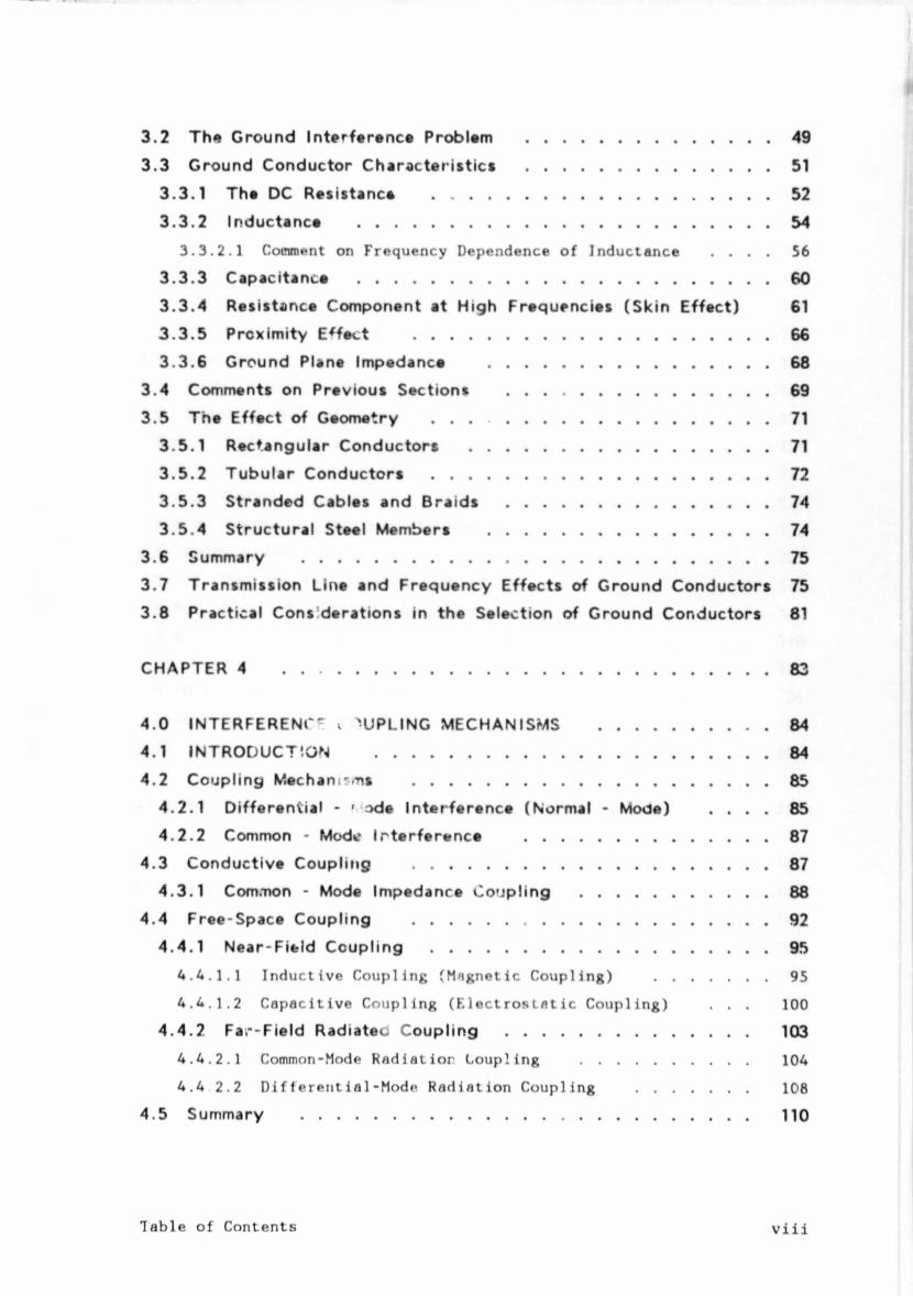
3.2 The Ground Interference Problem .....................................................493.3 Ground Conductor Characteristics .....................................................51
3.3.1 The DC Resistance .........................................................................523 .3 .2 Inductance ......................................................................................... 54
3.3.2.1 Comment on Frequency Dependence of Inductance . . . . 56
3.3 .3 Capacitance .........................................................................................603 .3 .4 Resistance Component at High Frequencies (Skin Effect) 613 .3 .5 Proximity Effect .............................................................................663 .3 .6 Ground Plane Impedance .............................................................68
3.4 Comments on Previous Sections .........................................................693.5 The Effect of Geometry .........................................................................71
3.5.1 Rectangular Conductors .................................................................713 .5 .2 Tubular Conductors .........................................................................723 .5 .3 Stranded Cables and Braids .........................................................743 .5.4 Structural Steel Members .............................................................74
3.6 Summary ..................................................................................................... 753.7 Transmission Line and Frequency Effects of Ground Conductors 753.8 Practical Considerations in the Selection of Ground Conductors 81
CHAPTER 4 ......................................................................................................... 83
4.0 INTERFERENCE v 'UPLING MECHANISMS .................................... 844.1 INTRODUCTION .....................................................................................844.2 Coupling Meehans-ns .............................................................................85
4.2.1 Differential - ' ode Interference (Normal - Mode) . . . . 854.2.2 Common - Mode I interference .....................................................87
4.3 Conductive Coupling .............................................................................874.3.1 Common - Mode Impedance Coupling ........................................ 88
4.4 Free-Space Coupling .............................................................................924.4.1 Near-Field Coupling .........................................................................95
4.4.1.1 Inductive Coupling (Magnetic Coupling) ..............95
4. 4. 1.2 Capacitive Coupling (F.lectrosiatic Coupling) . . . 100
4.4.2 Far-Field Radiateo Coupling .................................................... 1034.4.2.1 Common-Mode Radiation Coupling ..................... 104
4.4 2.2 Differential-Mode Radiation Coupling .............. 108
4.5 Summary ................................................................................................. 110
Table of Contentsviii
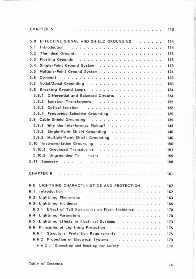
5.0 EFFECTIVE SIGNAL a ND SHIELD GROUNDING5.1 Introduction .........................................................5.2 The Ideal Ground. .............................................5.3 Floating Grounds .................................................5.4 Single-Point Ground System .............................5.5 Multiple-Point Ground System ........................5.6 Comment .................................................................5.7 Nodal/Zonal Grounding .....................................5.8 Breaking Ground Loops .....................................
5.8.1 Differential and Balanced Circuits . . . !/.6.2 Isolation Transformers ............................5 .8.3 Optical Isolation ............................................5 .8.4 Frequency Selective Grounding . ... ,
5.9 Cable Shield Grounding ........................................5.9.1 Why the Interference Pickup? ................ ...5.9.2 Single-Point Shield Grounding ................ ...5 .9.3 Multiple-Point ShieM Grounding . . . . ,
5.10 Instrumentation Grounoing ................................5.10.1 Grounded Transducers ................................5.10.2 Ungrounded Tr , -xer* ........................
5.11 Summary . . . . ........................................
LIGHTNING CHARACT ISTICS AND PROTECTION Introduction ..................................................................... Lightning Phenomena ............................................. Lightning Incidence .................................................
Effect of Tall Structures on Flash Incidence Lightning Parameters ..................................................... Lightning Effects in Electrical Systems ................
6.6 Principles of Lightning Protection ............................ Structural Protection Requirements ................ Protection of Electrical Systems ........................
6.6.2.1 Grounding and Bonding for Safety . . . .179
Table of Contentsix
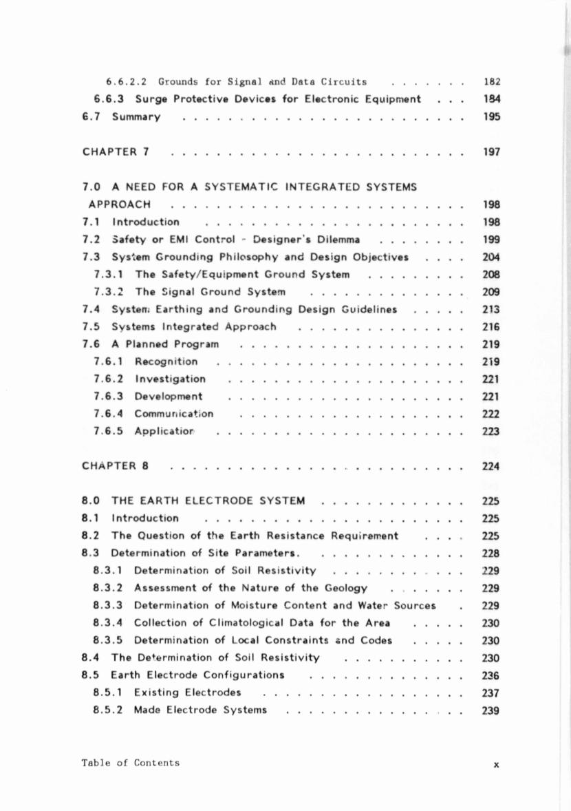
6.6.2.2 Grounds for Signal and Data Circuits .............. 162
6.6 .3 Surge Protective Devices for Electronic Equipment . . . 1846.7 Summery ................................................................................................. 195
CHAPTER 7 ..................................................................................................... 197
7.0 A NEED FOR A SYSTEMATIC INTEGRATED SYSTEMS APPROACH ..................................................................................................... 198
7.1 Introduction ......................................................................................... 1987.2 Safety or EMI Control - Designer's Dilemma ............................ 1997.3 System Grounding Philosophy and Design Objectives . . . . 204
7.3.1 The Safety/Equipment Ground System ................................ 2087.3.2 The Signal Ground System .................................................... 209
7.4 System Earthing and Grounding Design Guidelines ................ 2137.5 Systems Integrated Approach ........................................................ 2167.6 A Planned Program ............................................................................. 219
7.6.1 Recognition ..................................................................................... 2197.6.2 Investigation ................................................................................. 2217.6.3 Development ................................................................................. 2217.6.4 Communication ............................................................................. 2227 6.5 Applicatior ..................................................................................... 223
CHAPTER 8 .........................................................„ ....................................... 224
8.0 THE EARTH ELECTRODE SYSTEM ................................................ 2258.1 Introduction ......................................................................................... 2258.2 The Question of the Earth Resistance Requirement . . . . 2258.3 Determination of Site Parameters......................................................... 228
8.3.1 Determination of Soil Resistivity ............................................ 2298.3.2 Assessment of the Nature of the Geology ........................ 2298.3.3 Determination of Moisture Content and Water Sources . 2298.3.4 Collection of Climatological Data for the Area ................ 2308.3.5 Determination of Local Constraints and Codes ................ 230
8.4 The Determination of Soil Resistivity ........................................ 2308.5 Earth Electrode Configurations .................................................... 236
8.5.1 Existing Electrodes .................................................................... 2378.5.2 Made Electrode Systems ............................................................ 239
Table of Contents x
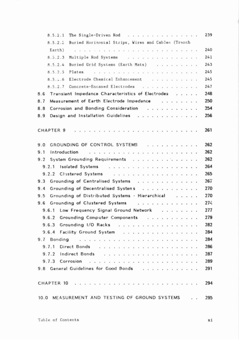
8.5.2.1 The Single-Driven Rod ................................ 239
8.5.2.1 Buried Horizontal Strips, Wires and Cables (Trench
Earth) ......................................................... 240
8.5.2.3 Multiple Rod Systems ................................ 241
8.5.2.4 Buried Grid Systems (Earth Mats) .................. 243
8.5.2.5 Plates ................................................ 245
8.5. *..6 Electrode Chemical Enhancement ..................... 245
8.5.2.7 Concrete-Encased Electrodes ......................... 247
8.6 Transient Impedance Characteristics of Electrodes ................ 2488.7 Measurement of Earth Electrode Impedance ............................ 2508.8 Corrosion and Bonding Consideration ........................................ 2548.9 Design and Installation Guidelines ................................................ 256
CHAPTER 9 ..................................................................................................... 261
9.0 GROUNDING OF CONTROL SYSTEMS ........................................ 2629.1 Introduction ......................................................................................... 2629.2 System Grounding Requirements ............................ ' ...................... 262
9.2.1 Isolated Systems ........................................................................ 2649.2.2 Clustered Systems .................................................................... 265
9.3 Grounding of Centralised Systems ................................................ 2679.4 Grounding of Decentralised Systens ............................................ 2709.5 Grounding of Distributed Systems - Hierarchical ................ 2709.6 Grounding of Clustered Systems ................................................ 274
9.6.1 Low Frequency Signal Ground Network ............................ 2779.6.2 Grounding Computer Components ........................................ 2799.6.3 Grounding I/O Racks ................................................................ 2829.6.4 Facility Ground System ............................................................ 284
9.7 Bonding ................................................................................................. 2849.7.1 Direct Bonds ................................................................................ 2869.7.2 Indirect Bonds ............................................................................ 2879.7.3 Corrosion ........................................................................................ 289
9.8 General Guidelines for Good Bonds ............................................ 291
CHAPTER 10 ..................................................................................................... 294
10.0 MEASUREMENT AND TESTING OF GROUND SYSTEMS . . 295
Table of Contents x i
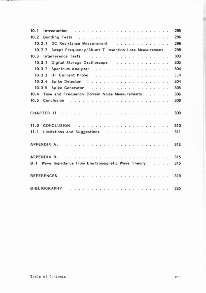
10.1 Introduction ......................................................................................... 29510.2 Bonding Tests ..................................................................................... 296
10.2.1 DC Resistance Measurement ................................................ 29610.2.2 Swept Frequency/Shunt-T Insertion Loss Measurement 298
10.3 Interference Tests ............................................................................. 30310.3.1 Digital Storage Oscilloscope ................................................ 30310.3.2 Spectrum Analyzer .................................................................... 30410.3.3 HF Current Probe ....................................................................10.3.4 Spike Detector ............................................................................ 30410.3.5 Spike Generator ........................................................................ 305
10.4 Time and Frequency Domain Noise Measurements ................ 30610.5 Conclusion ............................................................................................. 308
CHAPTER 11 ..................................................................................................... 309
11.0 CONCLUSION ............................................................................. 31011.1 Limitations and Suggestions ........................................................ 311
APFENDIX A .......................................................................................................... 313
APPENDIX B .......................................................................................................... 315B.1 Wave Impedance from Electromagnetic Wave Theory . . . . 315
REFERENCES ................................................................................................. 319
BIBLIOGRAPHY ............................................................................................. 335
Table of Contents xii
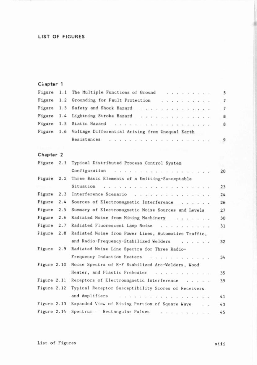
LIST OF FIGURES
Ci.apter 1
Figure 1.1 The Multiple Functions of Ground .................. 5
Figure 1.2 Grounding for Fault Protection ..................... 7
Figure 1.3 Safety and Shock Hazard .............................. 7
Figure 1.4 Lightning Stroke Hazard .............................. 8
Figure 1.5 Static Hazard ......................................... 8
Figure 1.6 Voltage Differential Arising from Unequal Earth
Resistances ............................................ 9
Chapter 2Figure 2.1 Typical Distributed Process Control System
Configuration ......................................... 20
Figure 2.2 Three Basic Elements of a Emitting-Susceptable
Situation .............................................. 23
Figure 2.3 Interference Scenario ................................ 24
Figure 2.4 Sources of Electromagnetic Interference ........... 26
Figure 2.5 Summary of Electromagnetic Noise Sources and Levels 27
Figure 2.6 Radiated Noise from Mining Machinery .............. 30
Figure 2.7 Radiated Fluorescent Lamp Noise ..................... 31
figure 2.8 Radiated Noise from Power Lines, Automotive Traffic,
and Radio-Frequency-Stabilized Welders ........... 32
Figure 2.9 Radiated Noise Line Spectra for Three Radio-
Frequency Induction Heaters ......................... 34
Figure 2.10 Noise Spectra of R-F Stabilized Arc-Welders, Wood
Heater, and Plastic Preheater ....................... 35
Figure 2.11 Receptors of Electromagnetic Interference ......... 39
Figure 2.12 Typical Receptor Susceptibility Scores of Receivers
and Amplifiers ....................................... 41
Fifure 2.13 Expanded View of Rising Portion of Square Wave . . 43
Figure 2.14 Spectrum Rectangular Pulses .................... 45
List of Figuresxiii
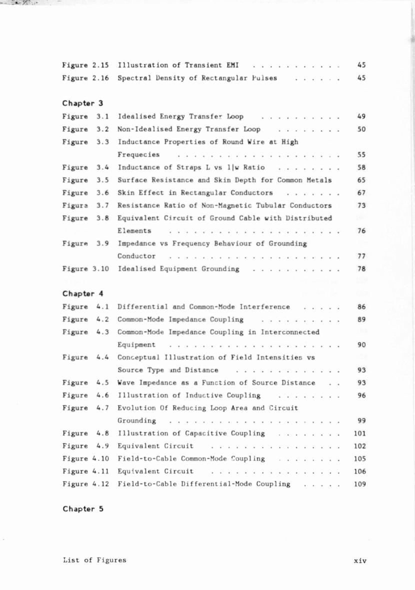
Figure 2.15
Figure 2.16
Chapter 3Figure 3.1
Figure 3.2
Figure 3.3
Figure 3.4
Figure 3.5
Figure 3.6
Figurs 3.7
Figure 3.8
Figure 3.9
Figure 3.10
Chapter 4Figure 4.1
Figure 4.2
Figure 4.3
Figure 4.4
Figure 4.5
Figure 4.6
Figure 4.7
Figure 4.8
Figure 4.9
Figure 4.10
Figure 4.11
Figure 4.12
Chapter 5
Illustration of Transient EMI ....................... .... 45
Spectral Density of Rectangular Pulses ........... .... 45
Idealised Energy Transfer Loop ......................... 49
Non-Idealised Energy Transfer Loop ................ .... 50
Inductance Properties of Round Wire at High
Frequecies ................................................ 55
Inductance of Straps L vs l|w Ratio ................ .... 58
Surface Resistance and Skin Depth for Common Metals 65
Skin Effect in Rectangular Conductors .................. 67
Resistance Ratio of Non-Magnetic Tubular Conductors 73
Equivalent Circuit of Ground Cable with Distributed
Elements .............................................. .... 76
Impedance vs Frequency Behaviour of Grounding
Conductor .............................................. .... 77
Idealised Equipment Grounding ....................... .... 78
Differential and Common-Mode Interference ......... 86
Common-Mode Impedance Coupling ..................... 89
Common-Mode Impedance Coupling in Interconnected
Equipment .............................................. 90
Conceptual Illustration of Field Intensities vs
Source Type ind Distance ............................ 93
Wave Impedance as a Function of Source Distance . . 93
Illustration of Inductive Coupling ................ 96
Evolution Of Reducing Loop Area and Circuit
Grounding .............................................. 99
Illustration of Capacitive Coupling ................ 101
Equivalent Circuit .................................. 102
Field-to-Cable Common-Mode Coupling ................ 105
Equivalent Circuit .................................. 106
Field-to-Cable Differential-Mode Coupling ......... 109
List of Figures xiv
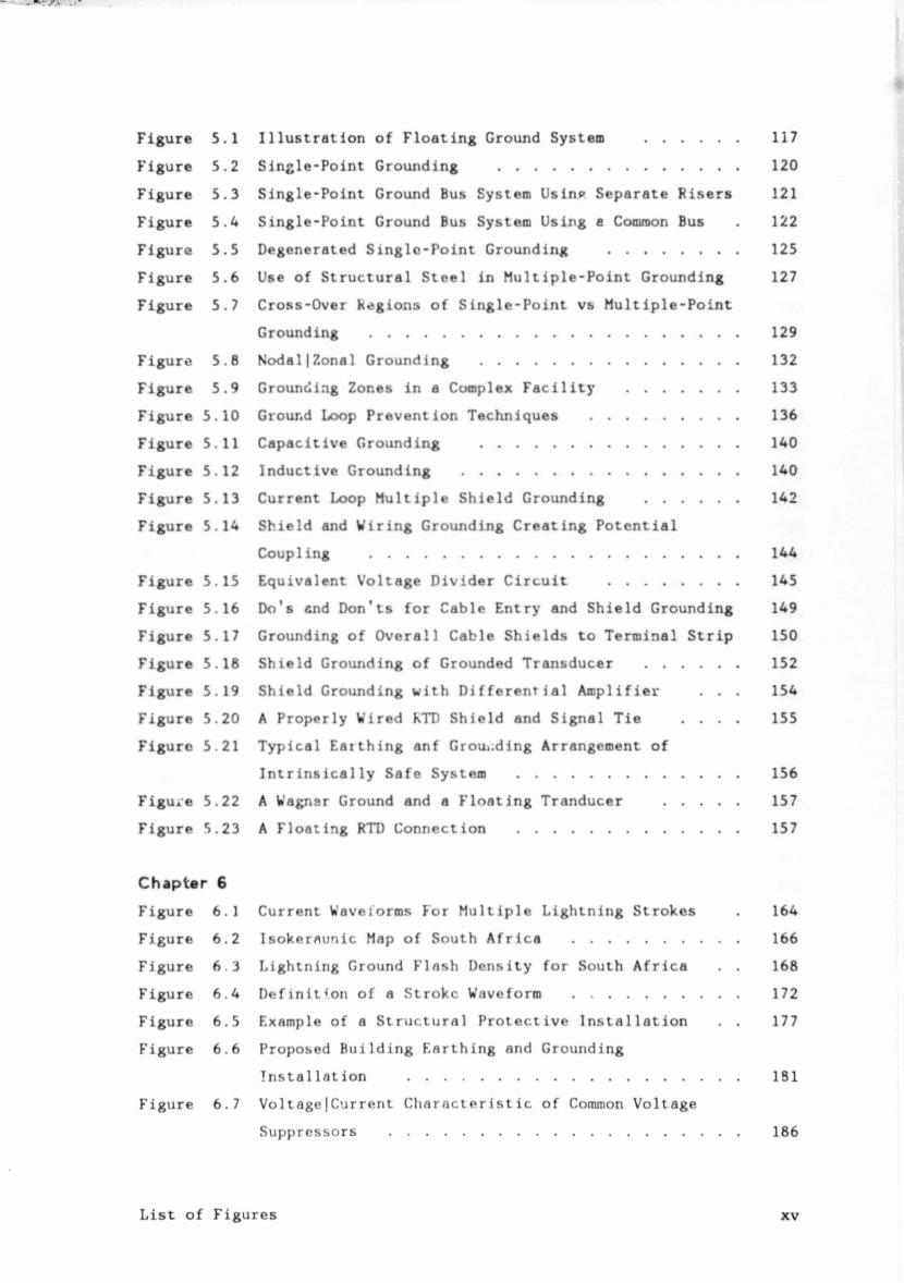
Figure 5.1 Illustration of Floating Ground System ............ 117
Figure 5.2 Single-Point Grounding ............................... 120
Figure 5.3 Single-Point Ground Bus System Usinp Separate Risers 121
Figure 5.4 Single-Point Ground Bus System Using e Common Bus . 122
Figure 5.5 Degenerated Singlc-Point Grounding ................. 125
Figure 5.6 Use of Structural Steel in Multiple-Point Grounding 127
Figure 5.7 Cross-Over Regions of Single-Point vs Multiple-Point
Grounding .............................................. 129
Figure 5.6 Nodal|Zonal Grounding ................................. 132
Figure 5.9 Grounding Zones in a Complex Facility .............. 133
Figure 5.10 Ground Loop Prevention Techniques ................... 136
Figure 5.11 Capacitive Grounding ................................. 140
Figure 5.12 Inductive Grounding ................................... 140
Figure 5.13 Current Loop Multiple Shield Grounding ............ 142
Figure 5.14 Shield and Wiring Grounding Creating Potential
Coupling .............................................. 144
Figure 5.15 Equivalent Voltage Divider Circuit ................. 145
Figure 5.16 Do's and Don’ts for Cable Entry and Shield Grounding 149
Figure 5.17 Grounding of Overall Cable Shields to Terminal Strip 150
Figure 5.18 Shield Grounding of Grounded Transducer ............ 152
Figure 5.19 Shield Grounding with Differential Amplifier . . . 154
Figure 5.20 A Properly Wired KTD Shield and Signal Tie . . . . 155
Figure 5.21 Typical Eaithing anf Grounding Arrangement of
Intrinsically Safe System ........................... 156
Figure 5.22 A Wagnar Ground and a Floating Tranducer .......... 157
Figure 5.23 A Floating RTD Connection ............................ 157
Chapter 6
Figure 6.1 Current Waveiorms For Multiple Lightning Strokes . 164
Figure 6.2 Isokeraunic Map of South Africa ...................... 166
Figure 6.3 Lightning Ground Flash Density for South Africa . . 168
Figure 6.4 Definition of a Stroke Waveform ..................... 172
Figure 6.5 Example of a Structural Protective Installation . . 177
Figure 6.6 Proposed Building Earthing and Grounding
Installation ......................................... 181
Figure 6.7 Voltage|Current Characteristic of Common Voltage
Suppressors ............................................ 186
List of Figures xv
Figure 6.8 General Circuit Arrangement for Primary and
Secondary Protection for Incoming Lines ............ 187
Figure 6.9 System Protective Concept ............................. 189
Figure 6.10 Examples of Signal Pair Protection ................. 190
Figure 6.11 Installation of Varistors for Lightning Protection
of Coaxial Cables ..................................... 192
Figure 6.12 Examples of Protection of Equipment Racks .......... 193
Figure 6.13 Examples of Protection of AC Mains Supply System . 194
Chapter 7
Figure 7.1 Typical on Site Power Ground Interconnections . . . 200
Figure 7.2 Single-Phase AC Power Ground Connections .......... 202
Figure 7.3 Three-Phase AC Power System Ground Connections . . 202
Figure 7.4 Scope of Grounding ................................... 205
Figure 7.5 The Three Questions of Grounding ................... 206
Figure 7.6 Facility Ground System ............................... 210
Figure 7.7 Possible Noise Sources for Separate Signal and
Equipment Grounding ................................... 212
Figure 7.8 Reduced Noise Plant Earthing and Grounding System . 214
Figure 7.9 Systems Integrated Approach to EMI Control . . . . 218
Figure 7.10 Systems Engineering Approach ........................ 220
Chapter 8
Figure 8.1 The Wenner Arrangemnt ................................. 234
Figure 8.2 Example of a Depth Curve ............................ 235
Figure 8.3 Single-Driven Rod ...................................... 239
Figure 8.4 Typical Buried Wire Configuration ................... 241
Figure 8.5 Typical Multiple Rod System .......................... 242
Figure 8.6 Typical Combination of Earth Rods and Grid Mesh . . 244
Figure 8.7 Chemical Enhancement of Earth Connection .......... 246
Figure 8 8 Earth Connection Using Concrete with Robar . . . . 247
Figure 8.9 Variation with Time of Surge Impedance ............ 249
Figure 8.10 Fa 11-of-Potent'a 1 Earth Resistance Measurement . . 252
Figure 8.11 Frequency Scanning Method ............................ 254
Figure 8.12 General Layout for Earth Electrode Around an
Irregular Structure ................................... 259
List of Figures
Figure 8.13 Electrode Configuration for Adjacent and
Interconnected Structures ........................... ...260
Chapter 9Figure 9.1 Different System Structures ......................... ...263
Figure 9.2 Grounding of AC Powered Isolated System ........... ...265
Figure 9.3 A Clustered System .................................. ...266
Figure 9.4 Power Grounding of Clustered System ................ ...268
Figure 9.5 Analog Signal Protection Outside the Earthing Area 273
Figure 9.6 Clean AC Power Source for Process Control Computer
System ................................................ ...276
Figure 9.7 Schematic of Low-Frequency Signal Ground Network . 278
Figure 9.8 Typical Single-Point Grounding with Some Common
Mistakes .............................................. ...280
Figure 9.9 Separate Analog and Digital Ground ................ ... 283
Figure 9.10 Elements of a Facility Ground System ................. 285
Figure 9.11 Equivalent Circuit of a Bonded System ................. 288
Figure 9.12 Finishing Around Dissimilar Metal Bonding Joints . 291
Chapter 10Figure 10.1 Bond Resistance Measurement ......................... ... 298
Figuie 10.2 Basis for Shunt-T Insertion Loss Measurement Method 300
Figure 10.3 Schematic Diagram of Details of Bond Test Fixture . 301
Figure 10.4 Swept Frequency System for Measuring Bond Impedance 302
Figure 10.5 Bond Impedance Displays ................................. 303
Figure 10.6 Stray Current Measurement with Current Probe . . . 305
Figure 10.7 Test Set-Up for Time and Frequency Domain
Measurement on Ground Systems ....................... ... 307
Appendix BFigure B.l Field of a !>hort Electric Di-Pole .................. ... 316
List of Figuresxvii
LIST OF TABLES
Table 3.1 Per Unit Length Resistance of Grounding Straps . . . 53
Table 3.2 Impedance of Straight Circular Copper Vires . . . . 57
Table 3.3 Impedance of Copper Straps ............................ 59
Table 3.4 Parameter K versus Ratio w|t .......................... 66
Table 3.5 Metal Ground Plane Impedance in Ohms Per Square . . 70
Table 6.1 Lightning Ground Flash Density for South Africa . . 169
Table 6.2 Flash Parameters ....................................... 171
Table 8.1 Resistivity of Soils ................................... 232
Table 8.2 Effect of Salt Content on Soil Resistivity .......... 232
Table 8.3 Effect of Moisture Content on Soil Resistivity . . . 232
Table 8.4 Effect of Temperature on Soil Resistivity-Sandy Loam 233
Table 8.5 Formulas for Calculation of Resistar.ce to Earth . . 238
Table 8.6 Relative Advantages and Disadvantages of the
Principle Types of Earth Electrodes ................ 257
Table 9.1 Electrochemical Series of Metals and Alloys . . . . 290
Table A.l Conversion Table ....................................... 313
List of Tables xviii
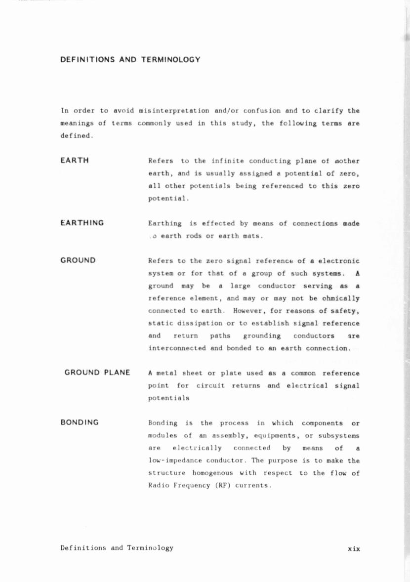
DEFINITIONS AND TERMINOLOGY
In order to avoid misinterpretation and/or confusion and to clarify the
meanings of terms commonly used in this study, the following terms are
defined.
EARTH Refers to the Infinite conducting plane of oother
earth, and is usually assigned 0 potential of zero,
all other potentials being referenced to this zero
potential.
EARTHING Earthing is effected by means of connections made
. 0 earth rods or earth mats.
GROUND Refers to the zero signal reference of a electronic
system or for that of a group of such systems. A ground may be a large conductor serving as a
reference element, and may or may not be ohmically
connected to earth. However, for reasons of safety,
static dissipation or to establish signal reference
and return paths grounding conductors are
interconnected and bonded to an earth connection.
GROUND PLANE A metal sheet or plate used as a common reference
point for circuit returns and electrical signal
potent ials
BONDING Bonding is the process in which components or
modules of an assembly, equipments, or subsystems
are e 1ectrica1ly connected by means of a
low-impedance conductor. The purpose is to make the
structure homogenous with respect to the flow of
Radio Frequency (RF) currents.
Definitions and Terminologyxix
IN T F R ,r RENCE
ELECTRICAL NOISE
SUSCEPTIBILITY
EMI
EMC
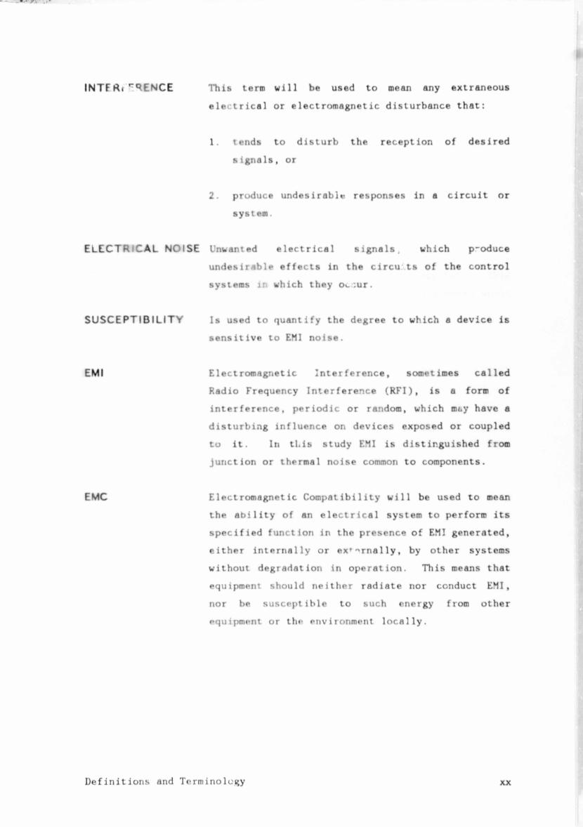
This tern will be used to mean any extraneous
electrical or electromagnetic disturbance that:
1. tends to disturb the reception of desired
signals, or
2. produce undesirable responses in a circuit or
system.
Unwanted electrical signals. which p-oduce
undesirable effects in the circu ts of the control
systems in which they Oi_:ur.
Is used to quantify the degree to which a device is
sensitive to EMI noise.
Electromagnetic Interference, sometimes called
Radio Frequency Interference (RFI), is a form of
interference, periodic or random, which mt.y have a
disturbing influence on devices exposed or coupled
to it. In this study EMI is distinguished from
junction or thermal noise common to components.
Electromagnetic Compatibility will be used to mean
the ability of an electrical system to perform its
specified function in the presence of EMI generated,
either internally or ex^rnally, by other systems
without degradation in operation. This means that
equipment should neither radiate nor conduct EMI,
nor be susceptible to such energy from other
equipment or the environment locally.
Definitions and Terminology xx
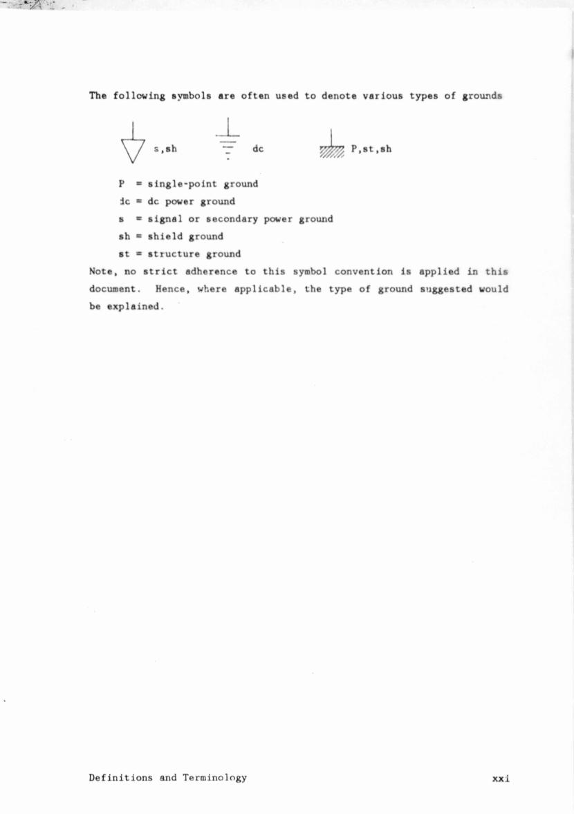
The following symbols are often used to denote various types of grounds
P * single-point ground
ic * dc power ground
s = signal or secondary power ground
sh « shield ground
st * structure ground
Note, no strict adherence to this symbol convention is applied in this
document. Hence, where applicable, the type of ground suggested would
be explained.
Definitions and Terminology xxi
dc
CHAPTER 1
CHAPTER 1
1.0 INTRODUCTION TO EARTHING AND GROUNDING
The r-odern industrial plant is increasingly characterised by
sophisticated microprocessor-based electronic instiumentation and process
cortrol systems Due to the complexity of these systems, total
malfunction and/or varying degrees of performance degradation are likely
to result unless the design of the system earthing and grounding is
approached methodically and from a total system perspective.
Many grounding systems are totally unstructured and the reason why some
systems work and ^thers do not, is never quite clear. It is wishful
thinking to expect a grounding system to work well if no thought is given
to its design. A grounding rule which is valid for shock or fire
protection at power frequencies may not be valid for the control of
Electromagnetic Interference (EMI) in a strong Ultra High Frequency (UHF)
environment. As with any circuit, a good ground system must be designed.
Thus a set of guidelines to assist in the design and installation of
earthing and grounding systems for industrial instrumentation and control
systems is required.
1.1 GOALS
The goal of this study Is v.o establish a proper perspective of the
functions of various earthing and grounding systems for electronic
installations and to present the scientific principles governing the
performance of grounding networks in all frequency regions. A set of
guidelines are to be developed to facilitate the correct analysis and
design of earthing and grounding networks for industrial instrumentation
and control installations where the prime objective is control of
Electromagnetic Interference (EMI).
Introduction To Earthing and Grounding2
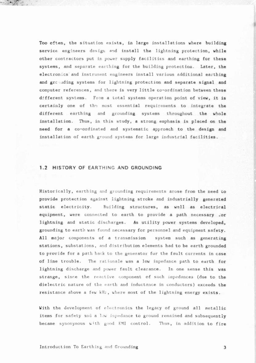
often, situation exists, installations
servicc. engineers design and install lightning protection,
contractors put in power supply facilities and earthing
and separate earthing for the building protection.
electronics and instrument engineers install various tdditiona! earthing
grc aiding systems for lightning protection separate
computer references, and there is very little co-ordination between
different systems. Fiore a total systems operation point it
certainly one of th'j most essential requirements integrate
earthing and grounding systems throughout
Thus, in this study, strong emphasis
co-ordinated and systematic approach
installation of earth ground systems for large industrial facilities.
Historically, earthing and giounding requirements arose from the need to
provide protection against lightning stroke and industrially generated
static electricity. Building structures, as well as electriral
equipment, were connected to earth to provide a path necessary »or
lightning and static discharges. As utility |>ower systems developed,
grounding to earth was found necessary for personnel and equipment safety.
All major components of a transmission system such as generating
stations, substations, and distribution elements had to be earth grounded
to provide for a path bark to the generator for the fault currents in case
of line trouble. The rationale was a low impedance path to earth for
lightning discharge and power fault clearance. In one sense this was
strange, s i m e the reactive component of such impedances (due to the
dielectric nature of the earth and inductance in conductors) exceeds the
resistance above a few kH;, where most of the lightning energy exists.
With the development of electronics the legacy of ground all metallic
items for safety and a low impedance to ground remained and subsequently
became synonymous with good F.MI control. Thus, in addition to fire
Introduction To Earthing and Grounding3
protection and mechanical reasons, not EMI reasons, metal became the usual
choice for structural narts surrounding the electrical and electronic
circuitry. This is a significant fact, for much of the cause for
grounding mystique (and dile.nma) can be related to the presence of metal.
The ready availability of something to ground to has obscured the real
reason why a ground is needed. In addition, the closeness of the metal
to electrical circuitry poses a possible shock hazard and EMI (when poorly
bonded). This leads to arguments about earthing the metal which obscures
the prior fact that the part should perhaps not have been metallic in the
(12)
first place . Thus it can be said that a thorough understanding of
the principles of grounding for purposes other than meeting the minimum
requirements of the electrical safety code has been lacking and that the
true function of signal grounding networks for the reduction of EMI has
been obscured.
1.3 WHY GROUND?
The terms "earthing" and "grounding" are very often confused or are used
to describe the wrong practice in electronics. Throughout the study, a distinction is drawn between thes» two terms. "Grounding" is intended
to relate to those measures or principles whereby electrical circuits are
interconnected and bonded to an earth connection, while, "Earthing" will
relate to the means of establishing an electrical connection to the mass
of the earth.
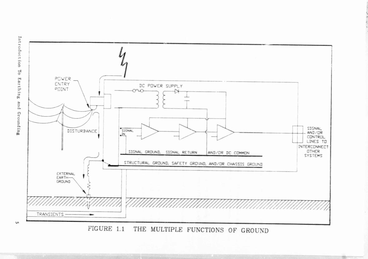
A situation commonly encountered is that of multiple electronic circuits
and equipment sharing common metallic paths which, in turn, may also serve
as power returns, lightning discharge paths, or an integral portion of
an electromagnetic shield (Figure 1.1). In such eases numerous currents
from various sources may be present in the common impedance path which
frequently leads to undesired EMI coupling. Hence, it can be said that
effective grounding should bo the realisation of an appropriate reference
network serving multiple roles without producing EMI between user
circuits and equipment.
Introduction To Earthing and Grounding4
WE 3
Introduction To Earthing and Grounding
5
FIGURE 1.1 THE MULTIPLE FUNCTIONS OF GROUND
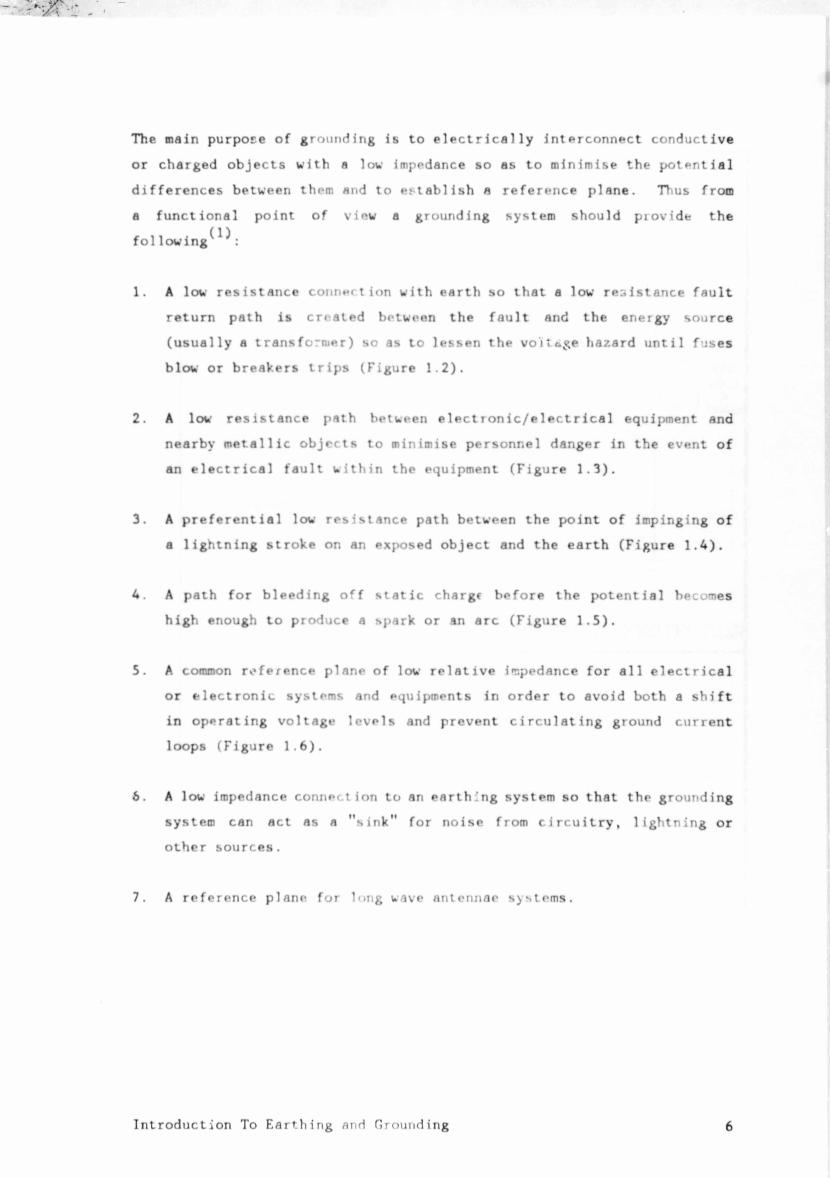
The main purpose of grounding is to electrically interconnect conductive
or charged objects with a low impedance so as to minimise the potential
differences between them and to establish n reference plane. Thus from
a functional point of view a grounding system should provide the
fol lowing^ ̂ :
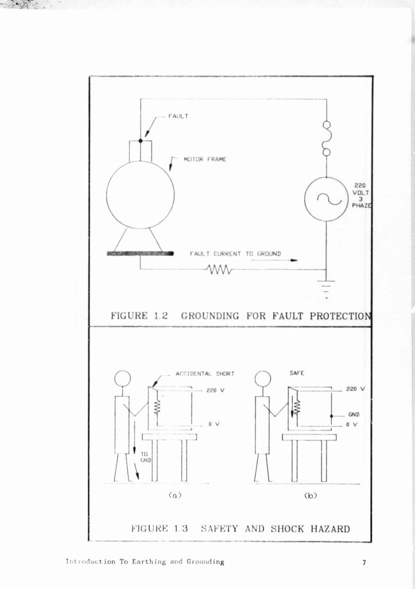
1. A low resistance Connert ion with earth so that a low resistance fault
return path is created between the fault and the eneigy source
(usually a transfo-nier) so as to lessen the voltage hazard until fuses
blow or breakers trips (Figure 1.2).
2. A low resistance path between electronic/electrical equipment and
nearby metallic objects to minimise personnel danger in the event of
an electrical fault within the equipment (Figure 1.3).
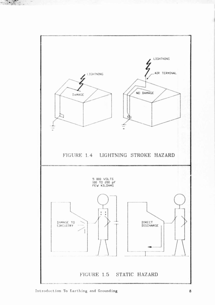
3. A preferential low resistance path between the point of impinging of
a lightning stroke on an exposed object and the earth (Figure 1.4).
4. A path for bleeding off static chargc before the potential becomes
high enough to produce a spark or an arc (Figure 1.5).
5. A common reference plane of low relative impedance for all electrical
or electronic systems and equipments in order to avoid both a shift
in operating voltage levels and prevent circulating ground current
loops (Figure 1.6).
6. A low impedance connection to an earthing system so that the grounding
system can act as a "sink" for noise from circuitry, lightning or
other sources.
7. A reference plane for long wave antennae systems.
Introduction To Earthing and Grounding 6
Introduction To Earthing and Grounding7
-' »•* —
UJ
Uz
&*& U q U m
o ar * ■* o-l I
z
£uuC
uD<H
d>
• i <
-X »-
k- (j r.;
or iu t't
< j u id ui ar
&
AM/V
(VI
t?cu
KA
►-4
I
9-*
%AM
II
> <3
13
* * «
-JM
OJ
X
UCZ
j U
J J Q S
U in U m
n ^ u a
jury fl
I
\AI-z
V u
< » cr a
►- D
ui o
CXJti
►H
«g •j <nr
T *- Ui - tj rJ
M J M
T I UJ i.) I.i cr
&
m(/>
U Jry rv
u a
, r
I
!
I
Introduction To Earthing and Grounding 9
FIGU
RE
1.6
- VO
LTAG
E D
IFFE
REN
TIAL
AR
ISIN
G FR
OM
UN
EQU
AL
EA
RTH
EL
ECTR
ODE
RESI
STAN
CES
AND
UN
EQU
AL
STRA
Y C
UR
RE
NTS
1.4 WHY EARTH?
Earthing, as already defined, is the process by which an electrical
connection is made to earth by means of an earth electrode system. Such
a system typically includes a network of rods, wires, pipes, counterpoises
or other configurations of m**tals (earth grid meshes) which establishes
electrical contact between the elements of the facility and the earth.
The earth system should, amongst others, achieve the following
(3)
objectives :
1. Insure that any faults to earth on the distribution system supplying
the facility have a sufficiently low impedance path back to the
substation or generating station to reliably cause transformer
station high voltage breakers to trip and clear the fault.
2. Provide a low impedance path for the discharge of lightning strokes
in such a manner that protects the structure, its occupants, and the
equipment inside.
3. Restrict the step-and-touch potential gradient in areas accessible
to persons to a level below the hazardous threshold even under
lightning discharge or power fault conditions.
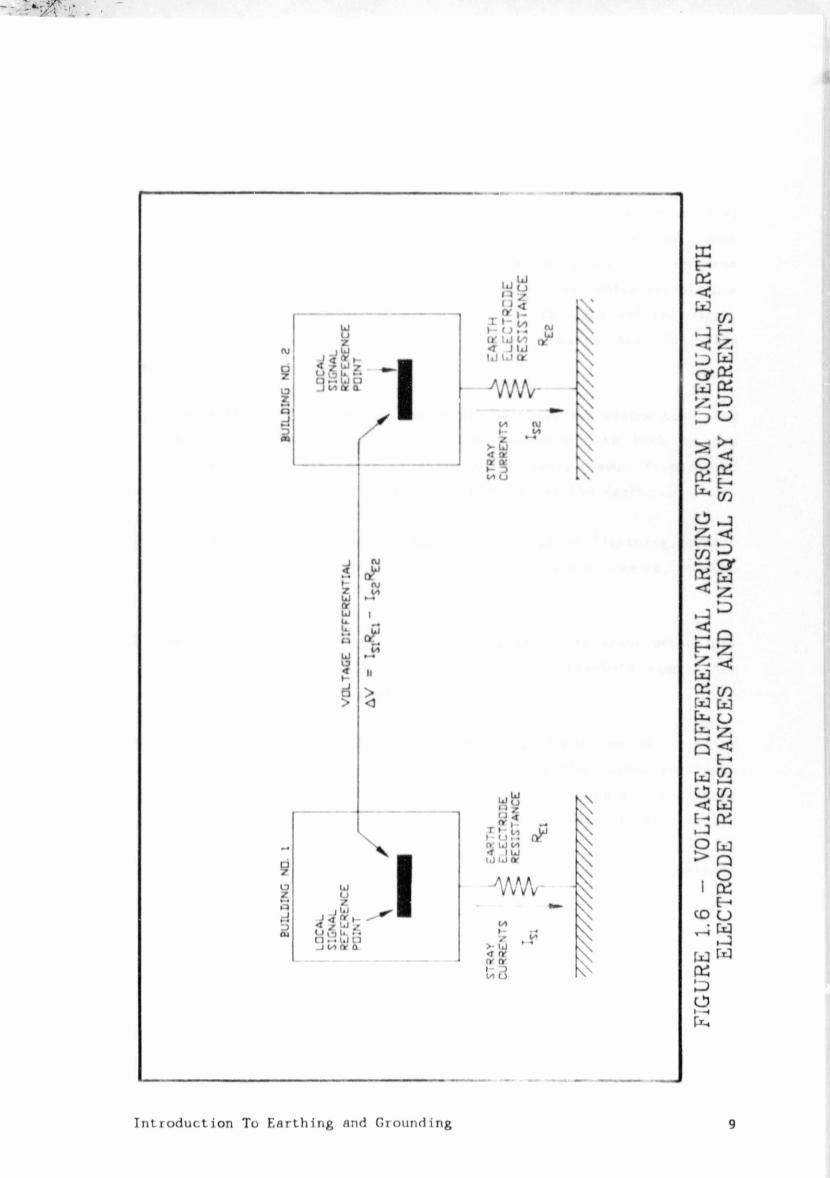
4. Assist in the control of interference in signal and control circuitry
by minimising voltage differentials between the signal reference
networks of separate facilities and also in preventing ground-current
loops which result in cc ,:imon-mode impedance coupling. (Figure 1.6)
5. Form a natural "sink" from atmospheric lightning and other natural
sources.
Introduction To Earthing and Grounding 10
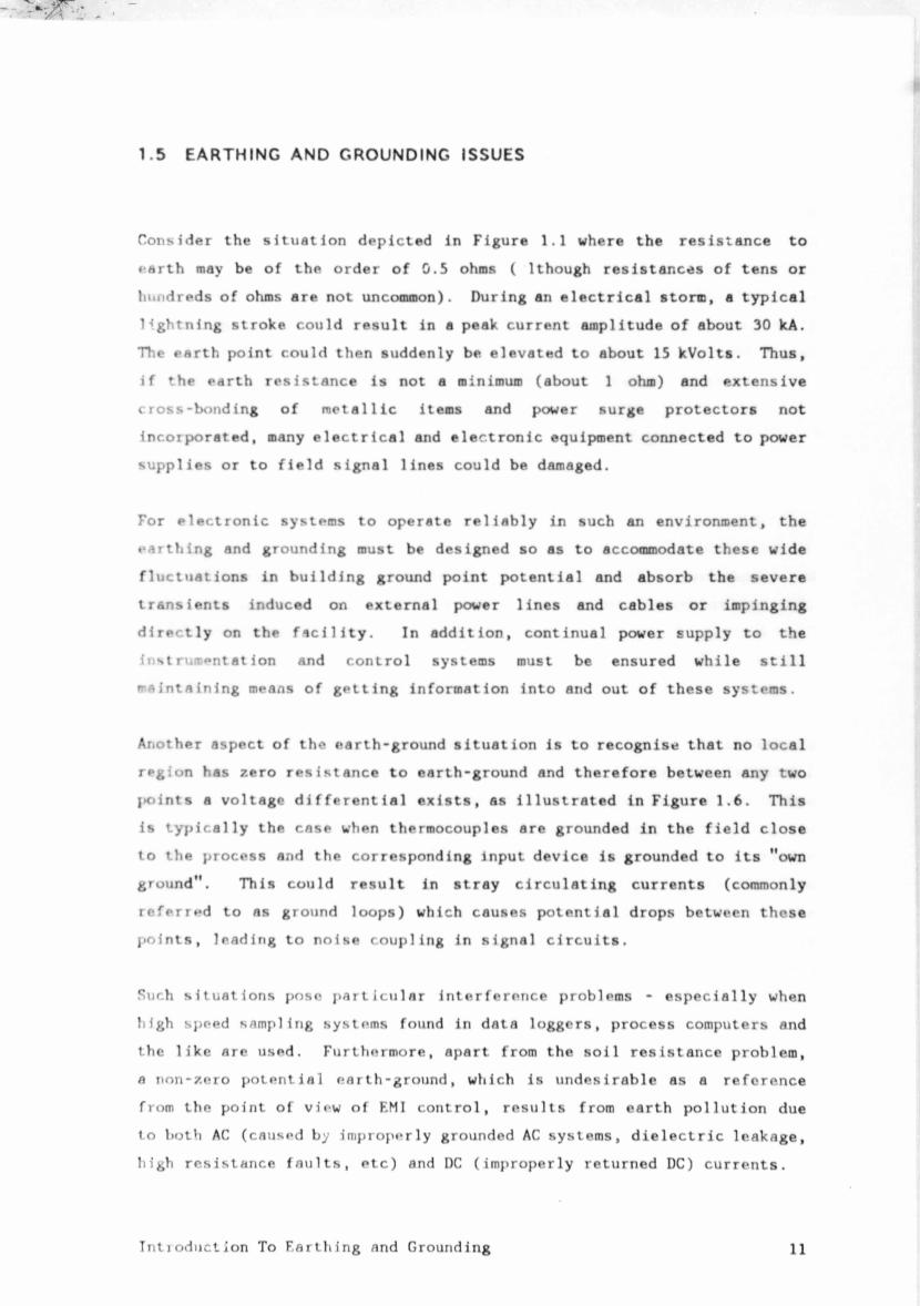
1.5 EARTHING AND GROUNDING ISSUES
Consider the situation depicted in Figure 1.1 where the resistance to
earth may be of the order of 0.5 ohms ( lthough resistances of tens or
hundreds of ohms are not uncommon). During an electrical storm, a typical
lightning stroke could result in a peak current amplitude of about 30 kA.
The earth point could then suddenly be elevated to about 15 kVolts. Thus,
if the earth resistance is not a minimum (about 1 ohm) and extensive
cross-bonding of metallic items and power surge protectors not
incorporated, many electrical and electronic equipment connected to power
supplies or to field signal lines could be damaged.
For electronic systems to operate reliably in such an environment, the
earthing and grounding must be designed so as to accommodate these wide
fluctuations in building ground point potential and absorb the severe
transients induced on external power lines and cables or impinging
directly on the facility. In addition, continual power supply to the
instrumentation and control systems must be ensured while still
n-aintaining means of getting information into and out of these systems.
Another aspect of the earth-ground situation is to recognise that no local
region has zero resistance to earth-ground and therefore between any two
l>oints a voltage differential exists, as illustrated in Figure 1.6. This
is typically the case when thermocouples are grounded in the field close
to the process and the corresponding input device is grounded to its "own
ground". This could result in stray circulating currents (commonly
referred to as ground loops) which causes potential drops between these
points, leading to noise coupling in signal circuits.
Such situations pose particular interference problems - especially when
high speed samp]ing systems found in data loggers, process computers and
the like are used. Furthermore, apart from the soil resistance problem,
a non-zero potential earth-ground, which is undesirable as a reference
from the point of view of F.MI control, results from earth pollution due
to both AC (caused by improperly grounded AC systems, dielectric leakage,
high resistance faults, etc) and DC (improperly returned DC) currents.
Introduction To Farthing and Grounding 11
The above serves to illustrate that * fng (^ud power) earth grounds
can conflict with EMI “control ref rei . •• > • *rtt ^ >unds (i.e signal and
instrumentation ground), either in t vs of ;• ational requirements or
in terms of techniques of implemeni*tinn A ’ ic intent of the remaining
chapters is to foster ar understai ng -ri t' •• 1 ectron.agnet i c properties
of ground networks and of the var '* t which affect the impedance
of earth and ground systems s t' * ’ • igners t.an .Tj^'ropriately
configure networks in fa ilities lit ' •••ms, equipni it and signal
circuits and have high a--grees o ^nf in their perfo ;ince.
1.6 SURVEY OF SUCCEEDING CHAP RS
The following chapters examine techniques and
practices pertaining of EMI.
The breakdown of the 11 •» :
Chapter 2 - The Inte^e-e-H * ^vito -n-
In this chapter, the ■'magnetic i ■ ,ient is described to
illustrate the wide * . .en< .*• ’ r levels Associated with
potential electromaK *t : --'rence ( " I) . ’ is FMT common
to the industrial •*: v r a M O t id* of and
the various victim tor •ments, p>- t ’ * level sensitive
electronic system pre 'ted IT | ible, graphical data
have been inclurt-d for { poses of an i il appraisal of the
interference env >nment. In /»ddii n, ’ e terferwnce signal is
characterised and examined in terms of n . hand, broad-hand, and
t rans ient EMI.
Chapter 3 - Characteristics of Ground Ciri nits
Introduction To Earthing and Grounding12
configurations. of establishing common ground or reference
planes is described. Mathematics),
formulae tables a m which give values of the resistance and
’■ conductors and straps. Ground
plane is relationships developed to
illustrate the high-frequency behaviour of grounding
conductors.
Chapter 4 - Interft* te Coupling Mechanisms
In this chapter coupling modes and mechanisms are identified and
analysed. common-mode impedance coupling, capacitive
coupling, ' pling and common-and-differential mode radiation
coupling. signal causes interference in circuits is
illustrated, p- ■? emphasis on the role of the ground circuit.
Basic guidelines established for interference reduction in ground
circuits as the basis for grounding concepts developed
in later
Chapter 5 - Effect v* Signal and Shield Grounding
Ground such as floating ground, single-point
grounding, hybrid grounding are discussed.
Guidelines wavelength considerations are provided
which aid of of the The problems of common
are examined and techniques
for presented. The question of where to ground
shields )!!. on frequency and circuit
sensitivity cons : <lr it for selecting either
shield grc..*iding. In addition, the aspects
of transducers through proper
Chapter 6 - I ightnify Characteristics and Protection
of the effects
eleitionic. systems. strike with a
Introduction To F.irthi and Grounding13
Author Ambelal Dependra
Name of thesis Earthing And Grounding For The Control Of Emi In Industrial Instrumentation And Control Systems. 1986
PUBLISHER: University of the Witwatersrand, Johannesburg
©2013
LEGAL NOTICES:
Copyright Notice: All materials on the Un i ve r s i t y o f the Wi twa te r s rand , Johannesbu rg L ib ra ry website are protected by South African copyright law and may not be distributed, transmitted, displayed, or otherwise published in any format, without the prior written permission of the copyright owner.
Disclaimer and Terms of Use: Provided that you maintain all copyright and other notices contained therein, you may download material (one machine readable copy and one print copy per page) for your personal and/or educational non-commercial use only.
The University of the Witwatersrand, Johannesburg, is not responsible for any errors or omissions and excludes any and all liability for any errors in or omissions from the information on the Library website.