eagle project mining permit application volume i · application eagle project mining permit...
TRANSCRIPT

Application
Eagle Project Mining Permit Application Volume I Project I.D.: 04W018
Kennecott Eagle Minerals Company Marquette, Michigan
February 2006
Printed on Recycled Paper


LJS\J:\scopes\04w018\10000\FVD reports\Final MPA\r-Mine Permit App text.doc
Distribution List
No. of Copies Sent To
2 Mr. Hal Fitch Michigan Department of Environmental Quality 525 West Allegan St Lansing, MI 48909
8 Mr. Joe Maki District Geologist Michigan Department of Environmental Quality 420 5th St Gwinn, MI 49841
1 Ms. Lynne Boyd Michigan Department of Natural Resources Forest, Mineral and Fire Management Mason Building P.O. Box 30452 Lansing, MI 48909
1 Mr. James Ekdahl Michigan Department of Natural Resources Upper Peninsula Field Deputy 1990 US Highway 41 S Marquette, MI 49855
2 Mr. Gene Smary Warner Norcross & Judd LLP 900 Fifth Third Center, 111 Lyon St, N.W. Grand Rapids, MI 49503-2489


LJS\J:\scopes\04w018\10000\FVD reports\Final MPA\r-Mine Permit App text.doc i
Eagle Project Kennecott Eagle Minerals Company
Mining Permit Application
Contents Page 1 Introduction .............................................................................................................................1
1.1 Background....................................................................................................................1 1.2 Mining Permit Application Documents .........................................................................1 1.3 Other Permits .................................................................................................................2 1.4 Document Preparers and Qualifications ........................................................................3 1.5 Checklist ........................................................................................................................5
2 Project Location Information ..................................................................................................6 2.1 Site Location ..................................................................................................................6 2.2 Land Use and Zoning.....................................................................................................6 2.3 Surface and Mineral Rights Ownership.........................................................................6 2.4 Conservation and Historical Preservation Easements....................................................6 2.5 Adjacent Properties and Measures Taken to Prevent Damage ......................................7
3 Eagle Project Geology.............................................................................................................8 4 Mining Plan .............................................................................................................................9
4.1 Project Development......................................................................................................9 4.1.1 Schedule for Construction................................................................................10 4.1.2 Operations Production Rates and Mining Methods .........................................11 4.1.3 Employment Schedule .....................................................................................12
4.2 Development Activities ...............................................................................................13 4.2.1 Topsoil Stripping, Stockpiling and Stabilizing................................................13 4.2.2 Facility Grading Plan .......................................................................................13 4.2.3 Excavation, Stockpiling and Earthwork Balance for Surface Structures ........14 4.2.4 Development Rock Excavation and Storage....................................................15 4.2.5 Geology and Ore Resources.............................................................................15 4.2.6 Geochemistry of Ore, Waste Rock and Peripheral Rock.................................17 4.2.7 Plans to Limit Access to the Facility ...............................................................17
4.3 Surface Facilities and Operations ................................................................................18 4.3.1 Site Access, Parking and Roads.......................................................................18 4.3.2 Buildings and Structures ..................................................................................18 4.3.3 Truck Wash and Scales....................................................................................19 4.3.4 Mine Portal.......................................................................................................19 4.3.5 Ore Conveying and Crushing...........................................................................20 4.3.6 Coarse Ore Storage Area .................................................................................21 4.3.7 Ore Transportation ...........................................................................................21 4.3.8 Ventilation Shaft ..............................................................................................21 4.3.9 Temporary Development Rock Storage Area..................................................21 4.3.10 Storm Water Management Systems.................................................................22
4.3.10.1 Operations Area Storm Water ..........................................................23

Contents (continued) Page
LJS\J:\scopes\04w018\10000\FVD reports\Final MPA\r-Mine Permit App text.doc ii
4.3.10.2 Non-Contact Storm Water................................................................23 4.3.10.3 Soil Erosion and Sediment Control Plan..........................................24 4.3.10.4 Soil Erosion and Sediment Control Plan During Construction........24 4.3.10.5 Soil Erosion and Sediment Control Plan During Operations...........26
4.3.11 Site Utilities .....................................................................................................26 4.3.11.1 Electric Service ................................................................................26 4.3.11.2 Mine and Surface Facilities Heating ................................................26 4.3.11.3 Telephone Service ............................................................................27 4.3.11.4 Potable Water ...................................................................................27 4.3.11.5 Sanitary System................................................................................27
4.3.12 Water Usage, Treatment and Discharge ..........................................................28 4.3.12.1 Wastewater Sources and Characteristics..........................................28 4.3.12.2 Water Balance ..................................................................................30 4.3.12.3 Wastewater Treatment System.........................................................30
4.3.13 Backfill Aggregate Stockpiles .........................................................................32 4.3.14 Security and Access Control............................................................................32 4.3.15 Aesthetics and Landscaping.............................................................................32 4.3.16 Fuel Handling and Chemical Storage ..............................................................32 4.3.17 Blasting Materials Handling and Storage ........................................................33 4.3.18 Spill Prevention and Countermeasures Plan ....................................................33
4.4 Underground Mine Description ...................................................................................34 4.4.1 Mine Design and Layout..................................................................................34 4.4.2 Mine Access.....................................................................................................36 4.4.3 Transverse Blasthole Stoping ..........................................................................37 4.4.4 Production Drilling and Blasting .....................................................................38
4.4.4.1 Production Drilling...........................................................................38 4.4.4.2 Production Blasting ..........................................................................38
4.4.5 Level Development and Stope Sequence.........................................................38 4.5 Underground Facilities.................................................................................................39
4.5.1 Mine Dewatering System.................................................................................39 4.5.2 Mine Ventilation Systems................................................................................40 4.5.3 Underground Ore Handling Systems ...............................................................41 4.5.4 Communication Systems .................................................................................41 4.5.5 Sanitation Systems ...........................................................................................42 4.5.6 Underground Electric Supply ..........................................................................42 4.5.7 Compressed Air System...................................................................................42 4.5.8 Mine Utility Water...........................................................................................42
4.6 Mine Backfill ...............................................................................................................42 4.6.1 Mine Stability and Subsidence Prevention ......................................................43
5 Treatment and Containment Plan for Mine Related Material ...............................................44 5.1 Temporary Development Rock Storage Area..............................................................44
5.1.1 Design Objectives of the TDRSA....................................................................44 5.1.2 Facility Location ..............................................................................................45 5.1.3 Design Volume ................................................................................................46 5.1.4 Subgrade Design ..............................................................................................46 5.1.5 Composite Liner...............................................................................................46

Contents (continued) Page
LJS\J:\scopes\04w018\10000\FVD reports\Final MPA\r-Mine Permit App text.doc iii
5.1.5.1 Geosynthetic Clay Liner (GCL) Equivalence ..................................47 5.1.5.2 Liner Stability Analysis....................................................................47 5.1.5.3 Chemical Compatibility of the TDRSA Liner System and Contact
Water ................................................................................................49 5.1.6 Water Collection System .................................................................................50 5.1.7 Contact Water Extraction System....................................................................51
5.1.7.1 Collection Pipe Clean Out................................................................52 5.1.8 Leak Detection System ....................................................................................52
5.2 TDRSA Operations......................................................................................................53 5.2.1 Filling Sequence...............................................................................................53 5.2.2 Temporary Cover .............................................................................................53 5.2.3 Removal Sequence...........................................................................................54
5.3 Quality Assurance and Quality Control for Liner and Cover Construction ................55 5.3.1 Field Testing and Inspections ..........................................................................55 5.3.2 Laboratory Testing...........................................................................................55 5.3.3 Certification Report .........................................................................................55
5.4 COSA...........................................................................................................................55 6 Operations Monitoring Plan ..................................................................................................57
6.1 Monitoring of the Temporary Development Rock Storage Area and Mine Water .....57 6.1.1 Leak Detection System ....................................................................................57 6.1.2 TDRSA Contact Water Collection System......................................................58 6.1.3 TDRSA and Mine Water Monitoring ..............................................................58
6.2 Groundwater Quality Monitoring ................................................................................60 6.2.1 Background Monitoring Wells ........................................................................60 6.2.2 TDRSA Monitoring Wells...............................................................................60 6.2.3 Contact Water Basin Monitoring Wells...........................................................60 6.2.4 Underground Mine...........................................................................................60 6.2.5 Groundwater Monitoring Parameters List .......................................................60
6.3 Regional Hydrologic Monitoring.................................................................................62 6.3.1 Surface Water Monitoring ...............................................................................62 6.3.2 Regional Groundwater Elevation Monitoring .................................................64
6.4 Groundwater and Surface Water Sampling Procedures...............................................64 6.5 Berms Embankments and Basins.................................................................................65 6.6 Biological Monitoring..................................................................................................65
6.6.1 Threatened and Endangered Species Monitoring ............................................66 6.6.2 Wetland Monitoring.........................................................................................66 6.6.3 Flora/Fauna Monitoring ...................................................................................66 6.6.4 Aquatics ...........................................................................................................67
6.7 Miscellaneous Monitoring Activities...........................................................................67 6.8 Minimization and Mitigation of Impacts .....................................................................67
7 Reclamation Plan...................................................................................................................70 7.1 Reclamation Sequencing and Timing ..........................................................................70 7.2 Final Land Use.............................................................................................................71 7.3 Site Construction Reclamation ....................................................................................72 7.4 Closure Reclamation....................................................................................................72
7.4.1 Surface Facilities..............................................................................................72

Contents (continued) Page
LJS\J:\scopes\04w018\10000\FVD reports\Final MPA\r-Mine Permit App text.doc iv
7.4.1.1 TDRSA.............................................................................................72 7.4.1.2 Roads and Access.............................................................................73 7.4.1.3 Buildings and Structures ..................................................................73 7.4.1.4 Surface Water Management Facilities .............................................73 7.4.1.5 Site Utilities......................................................................................73 7.4.1.6 Sanitary System................................................................................74 7.4.1.7 Potable Water System ......................................................................74 7.4.1.8 Water Treatment System..................................................................74 7.4.1.9 Earth Grading and Topsoil Placement .............................................74 7.4.1.10 Revegetation.....................................................................................75 7.4.1.11 Erosion Control ................................................................................75
7.4.2 Underground Facilities.....................................................................................75 7.4.2.1 Mineral Extraction Areas .................................................................75 7.4.2.2 Ore Handling Systems......................................................................75 7.4.2.3 Ventilation Systems..........................................................................76 7.4.2.4 Electrical and Other Utilities............................................................76 7.4.2.5 Sanitary Systems ..............................................................................76 7.4.2.6 Dewatering Systems.........................................................................76 7.4.2.7 Mechanical Equipment.....................................................................76 7.4.2.8 Underground Openings and Portal ...................................................76
7.4.2.8.1 Reclamation of Underground Openings..........................77 7.4.2.8.2 Mine Portal ......................................................................78
7.5 Post-Closure Care and Monitoring ..............................................................................78 7.5.1 Post-Closure Care ............................................................................................78 7.5.2 Post-Closure Monitoring Plan .........................................................................78
7.5.2.1 Post Reclamation Groundwater Monitoring Plan ............................78 7.5.2.2 Post Reclamation Surface Water Quality Monitoring Plan..............80 7.5.2.3 Biological Monitoring ......................................................................80 7.5.2.4 Sampling Protocols ..........................................................................80
7.6 Reclamation Costs .......................................................................................................82 8 Contingency Plan...................................................................................................................86
8.1 Contingency Items .......................................................................................................86 8.1.1 Release of Toxic or Acid-Forming Materials ..................................................86
8.1.1.1 Coarse Ore Storage Area..................................................................87 8.1.1.2 Temporary Development Rock Storage Area ..................................87 8.1.1.3 Ore Transportation ...........................................................................88
8.1.2 Storage, Transportation and Handling of Explosives ......................................89 8.1.3 Fuel Storage and Distribution ..........................................................................89 8.1.4 Fires..................................................................................................................91
8.1.4.1 Mine Fire ..........................................................................................91 8.1.4.2 Surface Fire ......................................................................................92
8.1.5 Wastewater Collection and Treatment.............................................................92 8.1.5.1 Contact Water Basins .......................................................................93 8.1.5.2 Non-Contact Storm Water................................................................93 8.1.5.3 Treated Water Infiltration System....................................................94
8.1.6 Berm Failures...................................................................................................94

Contents (continued) Page
LJS\J:\scopes\04w018\10000\FVD reports\Final MPA\r-Mine Permit App text.doc v
8.1.7 Air Emissions...................................................................................................94 8.1.7.1 Fugitive Emissions During Construction .........................................95 8.1.7.2 Air Emissions During Operations ....................................................95 8.1.7.3 Air Emissions During Reclamation..................................................96
8.1.8 Spills of Hazardous Substances .......................................................................96 8.1.9 Other Natural Risks..........................................................................................97 8.1.10 Power Disruption .............................................................................................98 8.1.11 Unplanned Subsidence.....................................................................................98 8.1.12 Containment System Leaks..............................................................................99
8.2 Emergency Procedures.................................................................................................99 8.3 Testing of Contingency Plan......................................................................................101
9 Financial Assurance.............................................................................................................103 9.1 Reclamation and Post-Closure Monitoring Costs......................................................103 9.2 Administrative Costs..................................................................................................103 9.3 Environmental Contingency Costs ............................................................................103 9.4 Operating Contingency Costs ....................................................................................103 9.5 Financial Assurance Instrument.................................................................................104 9.6 Standards for Release of Financial Assurance...........................................................104
10 References ...........................................................................................................................105
Tables Table 1-1 Document Preparation – List of Contributors..........................................................3 Table 4-1 Annual Production Schedule..................................................................................12 Table 4-2 Projected Employment...........................................................................................12 Table 4-3 Earthwork Balance.................................................................................................14 Table 4-4 Annual Development Rock Balance - Tonnes.......................................................15 Table 4-5 Geological Resource by Zone................................................................................17 Table 4-6 Geological Resource by Class ...............................................................................17 Table 4-7 Proposed Major Surface Facility Buildings...........................................................19 Table 4-8 Design Capacity Non-Contact Water Infiltration Basins.......................................24 Table 4-9 Mine Backfill Requirements ..................................................................................42 Table 5-1 Summary of TDRSA Stability Analysis ................................................................48 Table 5-2 Summary of Stability Analysis for Liner System..................................................49 Table 5-3 Summary of Geotextile Strength Calculations ......................................................51 Table 5-4 TDRSA Development Rock Filling.......................................................................53 Table 6-1 Leak Detection Sump Water Quality Parameter List ............................................58 Table 6-2 TDRSA and Mine Water Parameter List and Sampling Frequency ......................59 Table 6-3 Groundwater Quality Monitoring Program Parameter List and Sampling Frequency........................................................................................61 Table 6-4 Surface Water Quality Monitoring Program Parameter List and Sampling Frequency ..............................................................................................63 Table 6-5 Miscellaneous Environmental Monitoring and Maintenance Activities ...............68 Table 7-1 Reclamation Sequence ...........................................................................................70 Table 7-2 Reclamation Activities...........................................................................................71
Contents (continued) Page
LJS\J:\scopes\04w018\10000\FVD reports\Final MPA\r-Mine Permit App text.doc vi
Table 7-3 TDRSA Reclamation .............................................................................................72 Table 7-4 Post-Reclamation Groundwater Quality Monitoring Program Parameter List and Sampling Frequency ...............................................................79 Table 7-5 Post Reclamation Surface Water Quality Monitoring Program Parameter List and Sampling Frequency ...............................................................81 Table 7-6 Reclamation and Monitoring Cost Estimate ..........................................................83 Table 7-7 Summary of Reclamation and Monitoring Costs...................................................85 Table 8-1 Chemical Reagents Used at the WWTP ................................................................97 Table 9-1 Financial Assurance Costs ...................................................................................104
Illustrations Illustration 4-1 3D Representation of the Section through Deposit looking North ................16 Illustration 4-2 3D Schematic of Underground Mine.............................................................35 Illustration 4-3 Emergency Escape Routes.............................................................................37 Illustration 4-4 Typical Stope Development Plan...................................................................38 Illustration 4-5 Groundwater Dewatering System..................................................................40
Figures (Figures are provided after page 106)
Figure 2-1 Project Location Figure 2-2 Michigamme Township Zoning Map Figure 2-3 Project Mineral Rights Figure 2-4 Project Surface Ownership Figure 4-1 Existing Site Conditions Figure 4-2 Site Development Plan and Topographic Map Figure 4-3 Project Facility Plan on Aerial Photograph Figure 4-4 Overall Project Timeline Figure 4-5 Overall Mine Section Figure 4-6 Facility Grading Plan Figure 4-7 Portal Plan and Sections Figure 4-8 Underground Material Handling Figure 4-9 Surface Material Handling - General Arrangement Figure 4-10 Surface Material Handling - Crusher Figure 4-11 Surface Material Handling - Crushed Ore Bins Figure 4-12 Exhaust Raise Fan Figure 4-13 Lined Operations Area Details Figure 4-14 Site Erosion Control Plans - Construction Phase Figure 4-15 Site Erosion Control Plans - Operations Phase Figure 4-16 Erosion Control Details Figure 4-17 Erosion Control Details Figure 4-18A Water Balance – Maximum Annual Precipitation and Mine Inflow

Contents (continued)
LJS\J:\scopes\04w018\10000\FVD reports\Final MPA\r-Mine Permit App text.doc vii
Figure 4-18B Water Balance - Average Annual Precipitation and Expected Case Mine Inflow Figure 4-19 Contact Water Basin - Typical Section and Details Figure 4-20 Mine Layout - 383 Meter Level Figure 4-21 Mine Layout - 353 Meter Level Figure 4-22 Mine Layout - 323 Meter Level Figure 4-23 Mine Layout - 293 Meter Level Figure 4-24 Mine Layout - 263 Meter Level Figure 4-25 Mine Layout - 248 Meter Level – Exhaust Level Figure 4-26 Mine Layout - 233 Meter Level Figure 4-27 Mine Layout - 203 Meter Level Figure 4-28 Mine Layout - 188 Meter Level Figure 4-29 Mine Layout - 173 Meter Level Figure 4-30 Mine Layout - 143 Meter Level Figure 4-31 Mining Method - Blasthole Stope and Backfill Figure 4-32 Mine Ventilation Schematic Figure 4-33 Backfill Plant Flow Diagram Figure 5-1 TDRSA Base Grades and Contact Water Collection System Figure 5-2 TDRSA Final Grades Figure 5-3 TDRSA Liner System and Temporary Cover Figure 5-4 TDRSA Typical Profile Along Internal Access Ramp Figure 5-5 TDRSA Contact Water Collection Trench Figure 5-6 TDRSA Contact Water Collection Sump and Leak Detection System Figure 5-7 TDRSA Filling/Covering Sequence Figure 5-8 TDRSA Cross Sections Figure 5-9 TDRSA Cross Sections Figure 6-1 Operations Groundwater Quality Monitoring Program Figure 6-2 Regional Surface Water Monitoring Stations Figure 6-3 Regional Groundwater Elevation Monitoring Locations Figure 6-4 Operations Biological Monitoring Programs Figure 6-5 Wetland Monitoring Well Locations Figure 6-6 Aquatic Sampling Locations Figure 7-1 Reclamation and Erosion Control Plan Figure 7-2 Reclamation Plan for Underground Workings Figure 7-3 Post-Reclamation Groundwater Quality Monitoring Plan Figure 7-4 Post-Reclamation Surface Water Quality Monitoring Plan

Contents (continued)
LJS\J:\scopes\04w018\10000\FVD reports\Final MPA\r-Mine Permit App text.doc viii
Appendices
Appendix A Mining Permit Application Forms and Checklist A-1 MDEQ Mining Permit Application A-2 MDNR Land Use Application Form A-3 MPA Checklist Appendix B Kennecott Organization Report Appendix C Geologic and Geotechnical Reports for the Eagle Project C-1 Geology of the Eagle Nickel-Copper Deposit C-2 Eagle Project Geotechnical Study C-3 Subsidence Analysis Report Appendix D Geochemical Analysis D-1 Phase 1 Eagle Project Geochemistry Study D-2 Phase II Eagle Project Geochemistry Study D-3 TDRSA Water Chemistry D-4 Mine Water Chemistry During Operations D-5 Post-Reflooded Mine Water Chemistry Appendix E Storm Water Design Calculations Appendix F HELP Model Analysis Appendix G Geotechnical Calculations G-1 TDRSA Stability Analysis G-2 TDRSA Access Ramp Stability Analysis Appendix H Contact Water Collection System Calculations H-1 Pump Capacity System Calculations H-2 Pipe Strength Calculations H-3 Geotextile Strength Calculations Appendix I TDRSA CQA Plan Appendix J NRCS Native Grass Planting Guide Note: The appendices listed above are contained in the following volumes: Volume IA: Appendix A through Appendix C Volume IB: Appendix D: Appendix D-1 Volume IC: Appendix D continued Appendix D-2 through Appendix D-5 Volume ID: Appendix E through Appendix J

LJS\J:\scopes\04w018\10000\FVD reports\Final MPA\r-Mine Permit App text.doc ix
Eagle Project Mining Permit Application
List of Abbreviations, Acronyms, and Symbols ARD Acid rock drainage cfm cubic feet per meter ºC degrees Celsius CFR Code of Federal Regulations CHMM Certified Hazardous Materials Manager COSA Coarse ore storage area CWB Contact water basin CR County road CRP Concentrate reduction process EIA Environmental Impact Assessment EPCRA Emergency Planning and Community Right to Know Act F.S. Factor of Safety Ft feet ft2 square feet ft/d feet per day FW footwall g/t grams/tonne g/cc grams per cubic centimeter gal gallons gpm gallons per minute GCL Geosynthetic clay liner HDPE High density polyethylene Hp horse power HSE Health and Safety or the Environment HW hanging wall IDS Inverse – distance – squared in. inches KEMC Kennecott Eagle Minerals Company Kg kilograms kW kilowatt LDS Leak Detection System LHD Load haul dumps M meters m3 cubic meters mil one thousandth of an inch mm millimeters MCL Michigan Compiled Laws MCRC Marquette County Road Commission MDEQ Michigan Department of Environmental Quality MDNR Michigan Department of Natural Resources MDOT Michigan Department of Transportation mg/l milligrams per liter MPA Mining Permit Application MSHA Mining Safety and Health Administration mW megawatt

List of Abbreviations (con’t)
LJS\J:\scopes\04w018\10000\FVD reports\Final MPA\r-Mine Permit App text.doc x
m2 square meters NCWIB Non-contact water infiltration basin NREPA Michigan Natural Resources and Environmental Protection Act OSHA Occupational Health and Safety Administration OSS On-site septic system % percent P.E. Professional Engineer P.G. Professional Geologist P.H. Professional Hydrologist PIPP Pollution Incident Prevention Plan psig pounds per square inch gauge PVC Polyvinyl chloride PWS Professional Wetland Scientist R Rule RAR Return air raise RP-20 Resources Production District 20 scfm static cubic feet per minute SCR Selective catalytic reduction SESC Soil Erosion and Sediment Control SPCC Plan Spill Prevention Control and Countermeasures Plan TDRSA Temporary development rock storage area tonnes (t) metric tonnes (1 tonne = 1.1 ton) TSM 24+ Temporary seed mixture 24+ TWIS Treated water infiltration system t/d tonnes per day t/yr tonnes per year ug/l micrograms per liter USEPA United States Environmental Protection Agency UTM Universal Transverse Mercator WWTP Wastewater treatment plant TDS Total dissolved solids Yd3 cubic yards Yr year
LJS\J:\scopes\04w018\10000\FVD reports\Final MPA\r-Mine Permit App text.doc xi
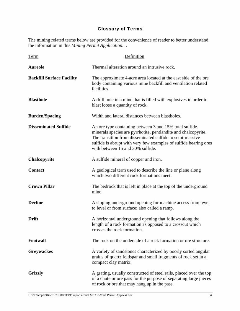
Glossary of Terms The mining related terms below are provided for the convenience of reader to better understand the information in this Mining Permit Application. . Term Definition Aureole Thermal alteration around an intrusive rock. Backfill Surface Facility The approximate 4-acre area located at the east side of the ore
body containing various mine backfill and ventilation related facilities.
Blasthole A drill hole in a mine that is filled with explosives in order to
blast loose a quantity of rock. Burden/Spacing Width and lateral distances between blastholes. Disseminated Sulfide An ore type containing between 3 and 15% total sulfide.
minerals species are pyrrhotite, pentlandite and chalcopyrite. The transition from disseminated sulfide to semi-massive sulfide is abrupt with very few examples of sulfide bearing ores with between 15 and 30% sulfide.
Chalcopyrite A sulfide mineral of copper and iron. Contact A geological term used to describe the line or plane along
which two different rock formations meet. Crown Pillar The bedrock that is left in place at the top of the underground
mine. Decline A sloping underground opening for machine access from level
to level or from surface; also called a ramp. Drift A horizontal underground opening that follows along the
length of a rock formation as opposed to a crosscut which crosses the rock formation.
Footwall The rock on the underside of a rock formation or ore structure. Greywackes A variety of sandstones characterized by poorly sorted angular
grains of quartz feldspar and small fragments of rock set in a compact clay matrix.
Grizzly A grating, usually constructed of steel rails, placed over the top
of a chute or ore pass for the purpose of separating large pieces of rock or ore that may hang up in the pass.
Glossary (con’t)
LJS\J:\scopes\04w018\10000\FVD reports\Final MPA\r-Mine Permit App text.doc xii
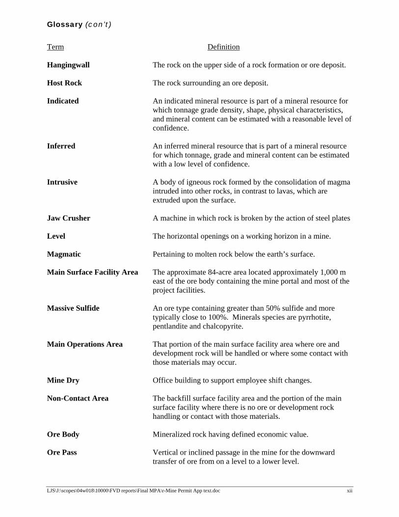
Term Definition Hangingwall The rock on the upper side of a rock formation or ore deposit. Host Rock The rock surrounding an ore deposit. Indicated An indicated mineral resource is part of a mineral resource for
which tonnage grade density, shape, physical characteristics, and mineral content can be estimated with a reasonable level of confidence.
Inferred An inferred mineral resource that is part of a mineral resource
for which tonnage, grade and mineral content can be estimated with a low level of confidence.
Intrusive A body of igneous rock formed by the consolidation of magma
intruded into other rocks, in contrast to lavas, which are extruded upon the surface.
Jaw Crusher A machine in which rock is broken by the action of steel plates Level The horizontal openings on a working horizon in a mine. Magmatic Pertaining to molten rock below the earth’s surface. Main Surface Facility Area The approximate 84-acre area located approximately 1,000 m
east of the ore body containing the mine portal and most of the project facilities.
Massive Sulfide An ore type containing greater than 50% sulfide and more
typically close to 100%. Minerals species are pyrrhotite, pentlandite and chalcopyrite.
Main Operations Area That portion of the main surface facility area where ore and
development rock will be handled or where some contact with those materials may occur.
Mine Dry Office building to support employee shift changes. Non-Contact Area The backfill surface facility area and the portion of the main
surface facility where there is no ore or development rock handling or contact with those materials.
Ore Body Mineralized rock having defined economic value. Ore Pass Vertical or inclined passage in the mine for the downward
transfer of ore from on a level to a lower level.

Glossary (con’t)
LJS\J:\scopes\04w018\10000\FVD reports\Final MPA\r-Mine Permit App text.doc xiii
Term Definition Ore Reserves The calculated tonnage and grade of mineralization which can
be economically extracted; classified as possible, probable and proven according to the level of confidence that can be placed in the data.
Outcrop An exposure of rock or mineral deposit that can be seen on
surface, that is not covered by soil or water. Pattern An arrangement of boreholes laid out in a blast area, expressed
in terms of burden and spacing measured in feet. Pentlandite A sulfide mineral of nickel and iron. Peridotite An ultramafic intrusive rock with less than 10% feldspar.
Olivine and pyroxene are the principal minerals species; Quartz is absent.
Portal The surface entrance to the mine. Powder Density Density of explosive package per blasthole. Proterozoic Time period extending from 2400 million years to 545 million
year before present. Pyrrhotite Iron sulfide. Raise A vertical or inclined underground working that has been
excavated from the bottom upward Rise Vertical distance of horizontal opening. Semi-Massive Sulfide An ore type containing between 30 and 50% total sulfide by
volume. Sulfide minerals species are pyrrhotite, pentlandite and chalcopyrite.
Spacing Distance in feet between boreholes in a row measured
perpendicular to the burden and parallel to the free face. Span Lateral distance of horizontal open. Stope An excavation in a mine from which ore is, or has been,
extracted. Sump An underground excavation where water accumulates before
being pumped to surface.
Glossary (con’t)
LJS\J:\scopes\04w018\10000\FVD reports\Final MPA\r-Mine Permit App text.doc xiv
Term Definition Transverse Blasthole Stoping The mining method chosen for the Eagle Project using 10 m
wide stopes extending from the north face to the south face of the ore body.
Ultramafic Rock deficient in quartz and rich in Mg-Fe minerals such as
olivine, pyroxene augite.

LJS\J:\scopes\04w018\10000\FVD reports\Final MPA\r-Mine Permit App text.doc Foth & Van Dyke and Assoc., Inc. • 1
1 Introduction Kennecott Eagle Minerals Company (KEMC) is proposing to develop an underground nickel and copper mine in Michigamme Township, Marquette County, Michigan. As part of the permitting process for the project, KEMC needs to apply for a Mining Permit in accordance with Part 632 of the Michigan Natural Resources and Environmental Protection Act (NREPA) (MCL §324.63201 et. seq.) and rules promulgated under R 425.101 et.seq. of the Michigan Administrative Code. This volume (Volume I) of the Mining Permit Application (MPA) and associated appendices contains required permit application forms; the mining, reclamation, environmental protection, and contingency; plans and financial assurance information as required in Part 632 and R 425.201(1)(a)(b)(d-h). Volume IA contains Appendices A through C that are referenced in this document. Volume IB contains Appendix D-1. Volume IC contains Appendices D-2 through D-5. Volume ID contains Appendices E through J. The Environmental Impact Assessment (EIA) required under Part 632 and R 425.201(1)(c) is contained in Volume II of this Mining Permit Application. Appendices for the EIA are contained in Volume IIA through Volume IIH. This MPA is based on engineering and other environmental studies as they relate to the design, construction, operation, closure, reclamation, and post-closure care of the Eagle Project facilities. The material presented in this application is representative of the type and size of facilities to be constructed and operated. 1.1 Background
The Eagle deposit is a high-grade magmatic sulfide deposit containing nickel and copper mineralization and minor amounts of cobalt, and gold. The Eagle deposit was discovered in 2002 by drilling areas known to contain sulfide-bearing peridotite intrusions. The economic minerals are predominately pentlandite and chalcopyrite. KEMC is proposing to mine the Eagle deposit by underground mining methods. Extracted ore will be brought to the surface where it will be crushed and trucked off-site along an approved trucking route to a railhead. The ore will be transferred to rail cars for shipment to an off-site processor. There will be no milling or chemical processing of ore at the Eagle Project site. As such, surface facilities for the operation will be limited to those necessary for storing and crushing ore; managing development rock; water storage, treatment and discharge; mine backfilling; mine ventilation; and, other ancillary operations. 1.2 Mining Permit Application Documents
This MPA is being submitted by KEMC to request a permit to mine at the Eagle Project site in Michigamme Township, Marquette County, Michigan. This volume (Volume I and associated Appendices in Volume IA through Volume ID) of the MPA includes the following items required under Part 632 and R 425.201(1)(a)(d-h):
♦ A permit application form for the Michigan Department of Environmental Quality (MDEQ) (Appendix A) along with a checklist to facilitate MDEQ review;
♦ A Michigan Department of Natural Resources (MDNR) Land Use Application Form for
leasing State Land that will be used for project surface facilities (Appendix A);

LJS\J:\scopes\04w018\10000\FVD reports\Final MPA\r-Mine Permit App text.doc Foth & Van Dyke and Assoc., Inc. • 2
♦ A permit application fee provided under separate cover by KEMC;
♦ A mining plan, containment plan, monitoring plan, reclamation plan and environmental protection plan (Sections 4, 5 ,6 and 7);
♦ A contingency plan (Section 8);
♦ A description of the amount of financial assurance that will be provided to satisfy the
requirements of R 425.301 (Section 9);
♦ A listing of other applicable permits and licenses that are being applied for concurrently with this MPA (Section 1.3);
♦ KEMC’s Organization Report (Appendix B); and
♦ An EIA (Volume II of this application).
This MPA includes the requirements of Part 632 of NREPA and Nonferrous Metallic Mineral Mining rules specified in R 425.101 et. seq. of the Michigan Administrative Code. This application is supported by tables and illustrations inserted within the narrative report and figures and appendices that follow the narrative report. The appendices contain technical reports, calculations and other data that support the designs presented in this application. 1.3 Other Permits
KEMC is concurrently applying for other permits required for operation of the Eagle Project. The anticipated permit applications are contained under separate cover in the format required by the respective regulatory agencies. These permit applications and related regulatory documents are as follows:
♦ A Michigan Air Use Permit – Permit to Install Application (Foth & Van Dyke, 2005a) submitted to the MDEQ for air emissions related to the proposed mine operation.
♦ A Groundwater Discharge Permit Application (Foth & Van Dyke, 2006) submitted to the
MDEQ for the treatment and discharge to the subsurface of treated water from the Eagle Project.
♦ Notice of Coverage for storm water management during construction activities and a
Notice of Intent for storm water management during operations will be submitted to the MDEQ for the potential release of non-contact storm water runoff.
♦ A Type II Non-Transient Non-Community Water Supply Permit Application will be
submitted to the Marquette County Health Department for water consumption and use by site workers.
♦ A Commercial Septic System Permit Application will be submitted to the Marquette
County Health Department for the treatment and discharge of sanitary wastewater generated by site workers.
LJS\J:\scopes\04w018\10000\FVD reports\Final MPA\r-Mine Permit App text.doc Foth & Van Dyke and Assoc., Inc. • 3
♦ A Mineral Extraction Permit Application (Foth & Van Dyke, 2005b) submitted to
Michigamme Township.
♦ Documentation will be submitted to the MDEQ, prior to construction, for certification of planned aboveground storage tanks for diesel fuel, gasoline and propane.
♦ A Spill Prevention Control and Countermeasures Plan (SPCC Plan) will be prepared per
40 CFR 112.
♦ A Pollution Incident Prevention Plan (PIPP) will be prepared per R 324.2001 et. seq. During operations KEMC will also file annual reports in compliance with the Federal Emergency Planning and Community Right to Know Act (EPCRA). As a result of the MDEQ’s review of the EIA, it is possible that other environmental permits may be identified for the Eagle Project. If other permit requirements are identified, KEMC will submit the applications as soon as possible. KEMC will begin construction of the Eagle Project after acquiring all environmental permits needed for the Eagle Project. 1.4 Document Preparers and Qualifications
This Mining Permit Application was prepared by Foth & Van Dyke and Associates, Inc. under contract to KEMC. This document incorporates information prepared by other qualified professionals working under contract to Kennecott and/or Foth & Van Dyke. The following is a summary of the organizations and individuals who have contributed to the preparation of this Mining Permit Application.
Table 1-1 Document Preparation – List of Contributors
Organization Individuals Qualifications BHE Environmental, Inc. 11733 Chesterdale Rd Cincinnati, OH 45246
Christopher Bergman, Ph.D, RPA
Archaeologist
ECT, Inc. 501 Avis Dr Ste 5C Ann Arbor, MI 48108
Donald Tilton, Ph.D., PWS John Freeland, Ph.D., PWS
Wetland Scientist Wetland Scientist
Fletcher Driscoll & Associates, LLC 1560 221st Ave. NW Oak Grove, MN 55011
Tom Davis, P.G.
Professional Geologist

Table 1-1 Continued)
LJS\J:\scopes\04w018\10000\FVD reports\Final MPA\r-Mine Permit App text.doc Foth & Van Dyke and Assoc., Inc. • 4
Organization Individuals Qualifications Foth & Van Dyke 2737 S Ridge Rd PO Box 19012 Green Bay, WI 54304
Stephen V. Donohue, P.H.(1)
John Starke, P.E.(1)
Steven Dischler, P.E. Ronald Meister, P.G.(1)
Janis S. Kesy, P.G. John Fassbender, P.E. Andrea Martin, P.E. Curtis Dungey, CHMM Gerald Eykholt, Ph.D., P.E. Michael Liebman , P.E.
Professional Hydrologist Professional Engineer Professional Engineer Professional Geologist Professional Geologist Professional Engineer Professional Engineer Air Quality/Meteorology Professional Engineer Professional Engineer
Golder Associates, Inc. 44 Union Blvd Ste 300 Lakewood, CO 80228
Scott H. Miller, P.G David Regalbutto, P.G. David Bare John Wozniewicz Kevin Beauchamp, P.E.
Professional Geologist Professional Geologist Air Quality/Meteorology Hydrogeologist Professional Engineer
Kennecott Eagle Minerals Company 1004 Harbor Hills Dr Ste 103 Marquette, MI 49855
Jonathan Cherry, P.E.(1)
Andrew Ware Alicia Duex
Professional Engineer Exploration Geologist Environmental Scientist
Kennecott Exploration #354-200 Granville St Vancouver, B.C. V6C 1S4
D. Rossell S. Coombes
Exploration Geologist Exploration Geologist
Kennecott Minerals Company 224 North 2200 West Salt Lake City, UT 84116
Fred Fox(1)
Director Health, Safety, Environment and Reclamation
King & MacGregor Environmental Inc. 2520 Woodmeadow Dr SE Grand Rapids, MI 49546
Doug Workman, Ph.D.
Aquatic Scientist
McIntosh Engineering, Inc. 1438 W Broadway Rd Ste 101 Tempe, AZ 85282
Sandy Watson
Mining Engineer
North Jackson Company 1004 Harbor Hills Dr PO Box 218 Marquette, MI 48909
Daniel Wiitala, P.G.
Professional Geologist

Table 1-1 Continued)
LJS\J:\scopes\04w018\10000\FVD reports\Final MPA\r-Mine Permit App text.doc Foth & Van Dyke and Assoc., Inc. • 5
Organization Individuals Qualifications Rio Tinto Technical Services 5295 South 300 West Ste 300 Murray, UT 84107
Roger Sawyer
Engineer
Wetland Coastal Resources 5801 W Michigan Ave Lansing, MI 48917
Hal Harrington Mike Nurse Stuart Kogge Carl Bennett
Biological Team Leader Wetland/Aquatic Scientist Wetland/Aquatic Scientist Wildlife Biologist
(1) Individuals involved with the preparation of reclamation plan. 1.5 Checklist
As part of this MPA a checklist has been prepared in reference to the rules to facilitate MDEQ review of this application. This checklist is provided in Appendix A.
LJS\J:\scopes\04w018\10000\FVD reports\Final MPA\r-Mine Permit App text.doc Foth & Van Dyke and Assoc., Inc. • 6
2 Project Location Information
2.1 Site Location
The proposed Eagle Project is located in Marquette County in the Upper Peninsula of Michigan, approximately 25 miles northwest of the city of Marquette and 10 miles southwest of the community of Big Bay. Figure 2-1 shows that the project is located on Triple A Road. 2.2 Land Use and Zoning
The Eagle Project is situated on the Yellow Dog Plains near the Salmon Trout River Main Branch. Land in the vicinity of the Eagle Project is primarily used for timber harvesting and recreational purposes. No permanent residences exist in the area. The closest populated area is Big Bay located approximate 10 miles to the northeast. The nearest known residences to the Eagle Project site are:
♦ A seasonal camp on Kennecott-owned land approximately 1.4 miles west-northwest of the mine portal.
♦ A seasonal camp known locally as Dodge City approximately 2.2 miles north of the mine
portal.
♦ A permanent residence approximately 6.4 miles east of the mine portal. The Eagle Project is located entirely in Sections 11 and 12, T50N-R29W, Township of Michigamme, Marquette County, Michigan. Figure 2-2 is a reproduction of the Michigamme Township Official Zoning Map “D/E” dated May 25, 1992 showing that the Eagle Project is located in Michigamme Township Zoning District RP-20. On land zoned as RP-20 (Resources Production Twenty), mineral extraction is a permitted principal use (Michigamme Township, 1992/1994). As noted earlier in this report, KEMC has submitted a Mineral Extraction Permit Application (Foth & Van Dyke, 2005b) to Michigamme Township for the Eagle Project. 2.3 Surface and Mineral Rights Ownership
KEMC owns a 100% interest in the Eagle Project site through a mixture of private mineral titles and state mineral leases and surface ownership. Figure 2-3 and Figure 2-4 show the location of the mineral title and leases and the surface ownership and leases, respectively. KEMC owns the surface title over the mineral deposit as shown in Figure 2-4. Two surface facilities will be constructed to support the Eagle Project. The aggregate backfill surface facility and vent shaft is located on KEMC-owned land near the ore body. The main project surface facilities are located on lands owned by the State of Michigan. KEMC leases the mineral rights on these state-owned lands and through the terms of the leases has the right to obtain a land use permit from the MDNR for the construction of mining related surface facilities. A copy of the MDNR Land Use Permit Application Form is provided in Appendix A. 2.4 Conservation and Historical Preservation Easements
In the summer of 2004, and summer of 2005, archaeologists from BHE Environmental Inc. completed a Phase I Archaeological Survey in an area around the main surface facility and backfill surface facility (BHE Environmental, 2005). This document is included in the
LJS\J:\scopes\04w018\10000\FVD reports\Final MPA\r-Mine Permit App text.doc Foth & Van Dyke and Assoc., Inc. • 7
Appendices for the EIA. The BHE Environmental, Inc., Phase I Archaeological Survey information determined the following:
♦ The Phase I Archaeological Survey yielded no evidence of prehistoric or historic occupation within the facility boundaries.
♦ A visual inspection of a larger areas surrounding the proposed surface facilities did
delineate a small scatter of prehistoric debris. Since the debris was discovered in a disturbed area of a utilized roadway the prehistoric context of the site could not be assessed.
♦ The Phase I Survey did not discover Paleo-Indian artifacts.
♦ The Phase I Survey did discover two historic-era occupations outside the area for the
proposed surface facilities which were most likely early to mid 20th-century logging camps. Both of these camps are situated adjacent to existing roads and both contain evidence of structural foundations.
BHE Environmental, Inc. concluded that there were no cultural properties potentially eligible or eligible to the NRHP (National Register of Historic Places) that exist within the surveyed areas. There are no known conservation or historic easements within 1,320 ft of the Eagle Project facilities. 2.5 Adjacent Properties and Measures Taken to Prevent Damage
The surface facilities for the Eagle Project include the main surface facility and the backfill surface facility displayed in Figure 2-4. With respect to the properties that border these surface facilities the following is noted:
♦ The backfill surface facility is located on KEMC owned property and there are no activities proposed that would impact adjacent properties since the surface activities are limited to an area of a few acres that border the Triple A Road.
♦ As of January 1, 2006,the main surface facilities are bordered by the following property
owners: State of Michigan and Plum Creek to the north; the State of Michigan and Longyear to the east; State of Michigan and KEMC property to the south; and KEMC property to the west.
The measures described in this permit application are proposed to prevent damage to adjacent properties not owned by KEMC.

LJS\J:\scopes\04w018\10000\FVD reports\Final MPA\r-Mine Permit App text.doc Foth & Van Dyke and Assoc., Inc. • 8
3 Eagle Project Geology Appendix C contains a report by Rossell and Coombes (2005) that describes the regional Precambrian geology and geology of the Eagle deposit. The EIA contained in Volume II of this Mining Permit Application provides a detailed description of the Quaternary geology and hydrogeologic characteristics of the local Precambrian and Quaternary formations relevant to the assessment of potential environmental impacts. Appendix C also contains geotechnical reports prepared by Golder Associates Ltd. (2005a and 2006) that present detailed analyses on the geotechnical characteristics of the bedrock conditions at the site relevant to the design and stability of the underground mine workings and prevention of surface subsidence.

LJS\J:\scopes\04w018\10000\FVD reports\Final MPA\r-Mine Permit App text.doc Foth & Van Dyke and Assoc., Inc. • 9
4 Mining Plan This section contains information presenting the proposed mining operations pursuant to R 425.203, including descriptions of general mining activities, surface and underground facilities and the overall mining plan. In reviewing the figures in this document, the reviewer will notice that both English and Metric units are used to describe units of measurement. The site plan is in UTM Zone 16 coordinates in meters. Thus planimetric elevation and horizontal coordinate appears in metric units of meters. Additional data with respect to topography and certain engineering details have been converted and/or presented in more common English units. 4.1 Project Development
The Eagle Project development will include surface and underground facilities required for the mining of the ore body. Figure 4-1 is an existing conditions map showing the location of the surface facilities and ore body. Figures 4-2 through 4-3 show the proposed Eagle Project surface facilities on a planimetric map and aerial photograph. The total surface area required for the project development is approximately 145 acres (fenced facility boundaries and access road). The project facility area (disturbed area) as shown on Figure 4-1 is approximately 92 acres. The location of the surface facilities was selected based upon:
♦ Proximity to the ore body, ♦ Minimizing disturbance to sensitive surface features and water bodies, ♦ Minimizing visual impacts from local roads, ♦ Accessibility to county and state roads, and ♦ Maintaining the natural topographic configuration of the property during operations and
post-reclamation periods. The proposed Eagle Project site includes the following facilities collectively referred to as the mine site.
♦ The main surface facilities that support the mine operation are located in the NW ¼ of Section 12, T50N, R29W and include the following:
Assay Lab Maintenance Shop and Compressor Plant Generator Plant Propane Storage and Mine Air Heater Laydown Area for Mining Supplies Contact Water Basins # 1 and # 2 (CWBs) Non-Contact Water Infiltration Basins # 3, # 4 and # 6 (NCWIBs) Loading Dock/Warehouse Emergency Response Facility Fuel Storage Area Temporary Development Rock Storage Area (TDRSA) Coarse Ore Storage Area (COSA) Crusher Ramp, Crusher, Conveyor and Crushed Ore Storage Bins Mine Portal Septic System Mine Dry/ Office Buildings Wastewater Treatment Plant (WWTP)

LJS\J:\scopes\04w018\10000\FVD reports\Final MPA\r-Mine Permit App text.doc Foth & Van Dyke and Assoc., Inc. • 10
Treated Water Infiltration System (TWIS) Potable Water Supply Well Non-Potable Water Storage Tank Visitor and Employee Parking Area Truck Wash Truck Scale Gate House Access Road Construction Staging Area Soil Stockpile Area Storage buildings for explosives
♦ The backfill facility located in the NE ¼ of Section 11, T50N, R29W includes the following:
Covered Aggregate Raise and Feed Hopper 110-ton Fly Ash Silo 110-ton Cement Silo Aggregate Storage Area Aggregate Raise Lined Binder Borehole NCWIB # 5 Exhaust Fan Housing
The ore body is located in the N½ of Section 11, T50N, R29W. Total rock excavation including mineable resource and development rock is estimated at approximately 4,100,000 tonnes. Except for the water treatment facilities, the entire project development from construction through operations and closure is expected to take approximately 11 years depending on ore production rates. Closure of the WWTP will occur in year 17. The overall project timeline is presented on Figure 4-4. 4.1.1 Schedule for Construction The schedule for the major activities involved in surface construction and underground development will take approximately 2 years. This schedule brings the mine on line in year 2 with full mine production occurring in year 3. The major construction activities for the Eagle Project are as follows: Phase 1 Surface Facilities Construction
♦ Construction of perimeter fence; ♦ Preparing the construction staging area and soil stockpile areas; ♦ Clearing, grubbing and stripping and stockpiling of topsoil; ♦ Construction of the mine site access road; ♦ Construction of the TDRSA; ♦ Construction of the WWTP; ♦ Construction of CWBs #1 and #2; ♦ Construction of the TWIS, and ♦ Construction of the NCWIBs.
LJS\J:\scopes\04w018\10000\FVD reports\Final MPA\r-Mine Permit App text.doc Foth & Van Dyke and Assoc., Inc. • 11
Phase 2 Surface Facilities Construction ♦ Construction of the generator plant and installation of the generators; ♦ Construction of the compressor plant and installation of the compressors; ♦ Construction of the maintenance shop, warehouse and office buildings; ♦ Construction of the COSA; ♦ Improvements to Triple A Road and CR 510; ♦ Construction of the surface crusher, crusher ramp and dump, conveyor and crushed ore
storage bins; ♦ Construction of surface backfill system facilities and power line to the generator plant;
and, ♦ Construction of miscellaneous remaining facilities, including the truck wash, scales, and
fuel storage area. Subsurface Facilities Construction Figure 4-5 shows an overall cross-section of the underground mine workings. The sequential order of subsurface facilities construction will include:
♦ Constructing the portal, established at approximate 444 m (meters above MSL). ♦ Constructing the main decline from surface to level 263 m, ♦ Constructing the backfill plant and lower levels of the main exhaust rise, ♦ Developing the main exhaust raise from the surface to the 263 m level, ♦ Developing the main decline from the 263 m to the 143 m level, ♦ Developing the 248 m level exhaust drift, ♦ Developing the 233 m, 203 m, 188 m, 173 m and 143 m level drifts, ♦ Constructing the aggregate raise and cement boreholes, ♦ Installing the emergency escape elevator, ♦ Developing the sump and pump stations at the 188 m and 143 m levels, ♦ Developing the interlevel return air raises below the 263 m level.
4.1.2 Operations Production Rates and Mining Methods The selected mining method proposed for the Eagle Project consists of 30 m (~98 ft) high by 10 m (~33 ft) wide and 15 m (~49 ft) high by 10 m (~33 ft) wide blasthole stoping. The length of the stope is based upon the ore cut-off grade. A small portion of the ore deposit may be mined using the blind bench mining technique. This method will be used to recover small high-grade zones outside of the designed blasthole stopes. The key criteria considered in the selection of the mining methods are as follows:
♦ Use bulk-mining methods to maintain maximum productivity;
♦ Maintaining high recovery rates of high grade ore;
♦ Minimize overall dilution rates due to the cost associated with transportation of crushed ore off-site for processing;
♦ Use a mine and backfilling process that is planned and designed to eliminate any
measurable surface subsidence.
LJS\J:\scopes\04w018\10000\FVD reports\Final MPA\r-Mine Permit App text.doc Foth & Van Dyke and Assoc., Inc. • 12
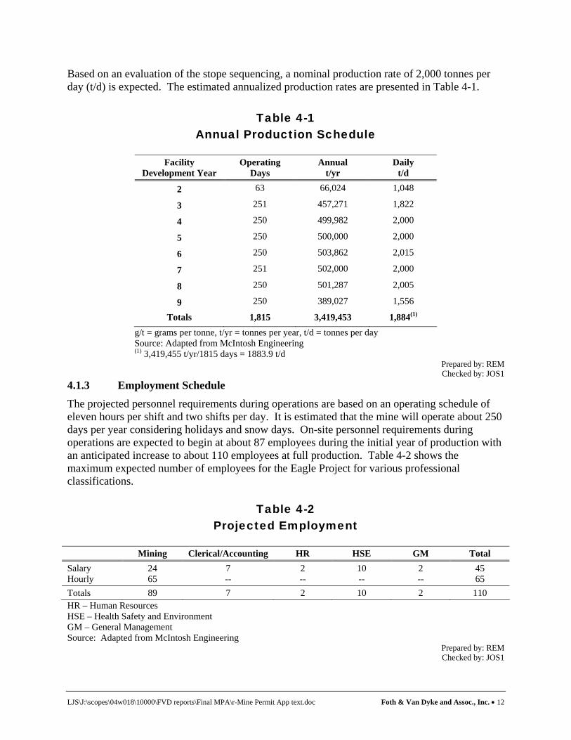
Based on an evaluation of the stope sequencing, a nominal production rate of 2,000 tonnes per day (t/d) is expected. The estimated annualized production rates are presented in Table 4-1.
Table 4-1 Annual Production Schedule
Facility
Development Year Operating
Days Annual
t/yr Daily
t/d
2 63 66,024 1,048
3 251 457,271 1,822
4 250 499,982 2,000
5 250 500,000 2,000
6 250 503,862 2,015
7 251 502,000 2,000
8 250 501,287 2,005
9 250 389,027 1,556
Totals 1,815 3,419,453 1,884(1) g/t = grams per tonne, t/yr = tonnes per year, t/d = tonnes per day Source: Adapted from McIntosh Engineering (1) 3,419,455 t/yr/1815 days = 1883.9 t/d
Prepared by: REM Checked by: JOS1
4.1.3 Employment Schedule The projected personnel requirements during operations are based on an operating schedule of eleven hours per shift and two shifts per day. It is estimated that the mine will operate about 250 days per year considering holidays and snow days. On-site personnel requirements during operations are expected to begin at about 87 employees during the initial year of production with an anticipated increase to about 110 employees at full production. Table 4-2 shows the maximum expected number of employees for the Eagle Project for various professional classifications.
Table 4-2 Projected Employment
Mining Clerical/Accounting HR HSE GM Total
Salary Hourly
24 65
7 --
2 --
10 --
2 --
45 65
Totals 89 7 2 10 2 110 HR – Human Resources HSE – Health Safety and Environment GM – General Management Source: Adapted from McIntosh Engineering
Prepared by: REM Checked by: JOS1
LJS\J:\scopes\04w018\10000\FVD reports\Final MPA\r-Mine Permit App text.doc Foth & Van Dyke and Assoc., Inc. • 13
4.2 Development Activities
Surface activities associated with the mine development include stripping and stockpiling of soils, and development of the TDRSA, CWBs, TWIS, and other surface facilities. 4.2.1 Topsoil Stripping, Stockpiling and Stabilizing The initial construction activities for the surface facilities will in general consist of the following:
♦ Installing erosion control devices such as siltation fences;
♦ Where necessary for facility construction, removal of marketable timber by a contractor;
♦ Removal of remaining trees and brush that will be chipped and stockpiled on-site for use in landscaping and reclamation of the mine site;
♦ Grubbing of roots and stumps that will be chipped or burned on-site;
♦ Stripping of the upper organic soil horizons (topsoil) from the area for reclamation, and
♦ Stockpiling and stabilizing the topsoil for later use in site landscaping and reclamation.
Based on the soil borings completed on the mine site, the average topsoil thickness is approximately three inches. The quantity of topsoil to be stripped from the site is estimated at approximately 28,600 cubic yards (yd3). The clearing, grubbing, topsoil stripping and stockpiling will be completed using conventional earth-moving equipment such as bulldozers, scrapers, graders and off-road trucks. Topsoil will be stockpiled in a controlled manner in the topsoil stockpile area. Topsoil and other soil stockpiles will be surrounded by silt fencing or similar erosion control devices to prevent soil erosion. In addition, topsoil stockpiles will be seeded with a Michigan Department of Transportation (MDOT), 2003 Standard Specification for Construction (MDOT, 2003) Temporary Seed Mixture 24+ (TSM 24+). TSM 24+ includes a 50/50 mixture of Perennial Ryegrass and Spring Oats. The rye and oats will quickly establish vegetation on the stockpile(s) and mitigate soil erosion and dusting until the topsoil is needed for site reclamation. 4.2.2 Facility Grading Plan
Upon completion of clearing and grubbing the area will be roughly graded as shown on Figure 4-6. The grading plan was designed to separate surface water runoff into zones for the main operations area and non-contact areas. The main operations area is the area of the facility that would be directly affected by mine activities. As such, storm water runoff from these areas will be collected in the CWBs. Non-contact areas are those areas which are not affected by mining activities associated with ore and development rock handling activities. Storm water runoff from these areas will be routed to the NCWIBs as shown on Figure 4-2. After rough grading is completed excavation for the TDRSA, CWBs, NCWIBs and other structures will be completed.

LJS\J:\scopes\04w018\10000\FVD reports\Final MPA\r-Mine Permit App text.doc Foth & Van Dyke and Assoc., Inc. • 14
4.2.3 Excavation, Stockpiling and Earthwork Balance for Surface Structures The preliminary earthwork balance is based on the design of the primary environmental protection structures that include the TDRSA, CWBs, NCWIBs and the TWIS. Note that grading for the other buildings and structures for the Eagle Project is considered incidental since these structures will, for the most part, be constructed at grade. Also, excavated rock during the mine development is not included in the earthwork balance since development rock will be temporarily stored in the TDRSA and eventually used as backfill in the mine stopes. Table 4-3 provides the earthwork balance for the facility construction as displayed on Figure 4-2. The cut needed to prepare the grades for the major facilities will be used to cover the TWIS and construct the soil berms. Excess soil from the site development will be placed in berms around the facility as shown on Figure 4-2. The soils placed in the berms will be used during the reclamation phase to return the mine site area to the reclamation grades. Also, if building and other structures need fill for the final design grades, this material can be removed from the stockpiled berms.
Table 4-3 Earthwork Balance
Structure Cut (-) (1)(yd3) Required Fill(2)
(+) (1)(yd3) Net (+/-) (1)(yd3) Comments Stripping/Stockpiling Topsoil 28,600(3) 11,400 +17,200
Refer to Note #3- Excess topsoil will be stockpiled
CWB #1(4) 28,800 1200 +27,600 -- CWB #2(4) 28,800 1200 +27,600 -- NCWIB #3(4) 15,700 1200 +14,500 -- NCWIB #4(4) 8,500 800 +7,700 -- NCWIB #5(4) 4,800 700 +4,100 -- NCWIB #6(4) 1,300 400 +900 -- TWIS5 ------- 29,800 -29,800 Five foot cover over
infiltration piping TDRSA 134,800 2,600 +132,200 -- Berms -------- 202,000 -202,000 See Figure 4-2
Total 251,300 251,300 0 Notes: CWB- Contact Water Basin NCWIB- Non-Contact Water Infiltration Basin TDRSA- Temporary Development Rock Storage Area TWIS- Treated Water Infiltration System (1) Cut, Fill and Net volumes are in cubic yards. Multiply cubic yards (yd3) by 0.7646 to get cubic meters (m3) (2) Cut/Fill volumes are rounded to the nearest one hundred yd3. (3) Topsoil quantity assumes an average of three inches across the mine and surface backfill sites. Also assumes that
40% of the total quantity will be used on-site during construction to revegetate the disturbed areas. (4) Assumes that CWB and NCWIB include a two-ft high berm around their perimeters, except the inlets, to prevent
surface water run-on. (5) Five feet of cover soils placed over TWIS distribution piping.
Prepared by: REM Checked by: JOS1

LJS\J:\scopes\04w018\10000\FVD reports\Final MPA\r-Mine Permit App text.doc Foth & Van Dyke and Assoc., Inc. • 15
4.2.4 Development Rock Excavation and Storage Prior to extraction of the ore, KEMC must remove rock from portals, drifts, raises, and ramps that are developed to access the ore body. This rock is referred to as development rock. Excavation of the subsurface mine facilities begins at the mine portal located on the west side of the rock outcrop as shown on Figure 4-2. Development rock excavated to access the ore body will be hauled to the surface using low-profile haul trucks and placed in the TDRSA and amended with limestone. Table 4-4 lists the estimated quantities in metric tons (tonnes) of development rock that will be produced during mine development and mining. Column 7 – Backfill Rock Balance – lists the annual rock balance based upon the backfill requirements for development rock. Excess development rock will be stored in the TDRSA for approximately 7 years. For the first 3 years of facility development, no stope backfilling is planned or required due to the sequential primary/secondary stope backfill plan which will maintain mine stability during this period. The peak tonnage of development rock to be stored in the TDRSA occurs in year 3, totaling 378,914 tonnes. Beginning with year 4, stored rock in the TDRSA will be reduced with mine backfilling.
Table 4-4 Annual Development Rock Balance – Tonnes
(1) Facility
Development Year
(2) Excavated
Development Rock
(3) Underground
Road Bed Requirements
(4) Subtotal
Development Rock
Balance
(5) Cumulative
Totals
(6) Secondary
Backfill Requirements
(7) Backfill Rock
Balance(1) (Col 7 + Col 4
– Col 6) 1 147,557 2,819 144,738 144,738 0 +144,738 2 178,359 3,796 174,563 319,301 0 +319,301 3 60,462 849 59,613 378,914 0 +378,914 4 72,811 840 71,971 450,885 143,599 +307,287 5 45,047 712 44,335 495,220 111,092 +240,530 6 63,171 1,295 61,876 557,096 189,435 +112,971 7 79,872 1,712 78,160 635,256 146,409 +44,722 8 22,055 475 21,580 656,836 136,496 -70,194 9 6,591 88 6,503 663,339 209,388 -273,079
Totals 675,925 12,586 663,339 936,419 -273,079 Source: Adapted from McIntosh Engineering 1 tonne (metric ton) = 1.102 ton (short ton) (1) Backfill deficit will be supplied by importation of aggregate
Prepared by: REM Checked by: JOS1
4.2.5 Geology and Ore Resources The Eagle nickel-copper sulfide mineralization is hosted in a 480-meter long, east-west-trending, ultramafic body which intrudes Proterozoic siltstones, sandstones, greywackes and slates. These sediments dip shallowly to the northeast and have been thermally metamorphosed in a 2-meter to 10-meter aureole around the ultramafic. Sediment-intrusive contacts are reasonably sharp and regular.

LJS\J:\scopes\04w018\10000\FVD reports\Final MPA\r-Mine Permit App text.doc Foth & Van Dyke and Assoc., Inc. • 16
The intrusive is predominantly peridotite, dips sub-vertically or steeply northwards and is covered by unconsolidated fluvial-glacial till and outwash. It tapers from 100 m (~328 ft) wide at surface to a 5 m (~16 ft) to 10 m (~33 ft) wide dyke at the base. No major faults have been identified that offset the intrusive. Oxidation is negligible and primarily confined to a few tens of meters below the Quaternary sediments. A 3D representation of the deposit is shown in Illustration 4-1.
Illustration 4-1 3D Representation of the Section through Deposit looking North
Source: Kennecott Minerals Company. The sulfide mineralization is divided into massive (>80% sulfide), semi-massive (30-80% sulfide) and disseminated (<30% sulfide) types. The massive sulfide and semi-massive sulfide are distinct phases of mineralization. The geologic resource model is based on information from exploration drill holes, and uses separate wire-framed bodies for the massive sulfide, the semi-massive sulfide and the ultramafic intrusion. Metal grades and densities were interpolated using an inverse-distance-squared (IDS) averaging routine. The total geologic resources based upon this modeling are shown in Tables 4-5 and 4-6. The projected mineable resource as presented in Table 4-1 is 3,419,453 tonnes which is approximately 42% of the total geologic resource (peridotite) and approximately 84% at the massive and semi-massive sulfide units.

LJS\J:\scopes\04w018\10000\FVD reports\Final MPA\r-Mine Permit App text.doc Foth & Van Dyke and Assoc., Inc. • 17
Table 4-5
Geologic Resource by Zone
Zone Tonnes
(million) Cu %
Ni %
Au g/t
Co g/t
Massive Sulfide 1.477 4.15 6.11 0.32 0.17 Semi-Massive Sulfide Western Zone 1.914 2.33 2.09 0.28 0.05 Eastern Zone 0.659 1.80 2.18 0.23 0.06 Total Semi-Massive Sulfide 2.573 2.19 2.12 0.27 0.06 Total MSU and SMSU 4.050 2.91 3.57 0.28 0.10 Peridotite 8.064 0.41 0.54 0.05 0.02
g/t = grams per tonne, % = percent Source: Kennecott
Prepared by: REM Checked by: JOS1
Table 4-6 Geologic Resource by Class
Class Tonnes
(million) Cu (%)
Ni (%)
Au (g/t)
Co (%)
Indicated 3.585 3.00 3.75 0.29 0.10 Inferred 0.465 2.20 2.21 0.22 0.06 Total 4.050 2.91 3.57 0.28 0.10
g/t = grams per tonne, % = percent Source: Kennecott
Prepared by: REM Checked by: JOS1
4.2.6 Geochemistry of Ore, Waste Rock and Peripheral Rock A detailed description of the geochemistry of the Eagle deposit is provided in the Eagle Project Phase I and Phase II geochemistry reports prepared by Geochimica, Inc. (2004 and 2005). Copies of these reports are provided in Appendix D. Descriptions of the geochemical analysis of the water pumped from the mine and TDRSA during operations, and post-reclamation underground water quality in the reclaimed mine are also provided in Appendix D. 4.2.7 Plans to Limit Access to the Facility Access to the facility will be limited by the following design features:
♦ The Eagle Project surface facilities will be surrounded by a 8-foot high chain link fence.
♦ A single access road is proposed for the main surface facility that is gated and has a gatehouse manned during facility operation.

LJS\J:\scopes\04w018\10000\FVD reports\Final MPA\r-Mine Permit App text.doc Foth & Van Dyke and Assoc., Inc. • 18
♦ The main surface facility is obscured from view by a tree covered rock outcrop and other
tree covered areas;
♦ The excess soil berms constructed around the majority of the facility will further obscure the facilities from view and restrict site access.
4.3 Surface Facilities and Operations
The surface facilities required to support the mining operations are shown on Figure 4-2 and are discussed in the following sections. Figure 4-6 shows the pre-construction-site grading plan for the surface facilities. Additional surface facilities may be added during operations if required to support mining or other operational needs. 4.3.1 Site Access, Parking and Roads Access to the Eagle Project will be via Triple A Road. The main access road will be surfaced with gravel for all-weather use. Entrance to the mine facilities will only be permitted through the main entrance gate as shown on Figure 4-2. At the main entrance will be a gate house with visitor parking. Employee parking is provided adjacent to the office/mine dry building. On-site access to the surface facilities will be provided by all-weather gravel roads. Construction of access roads will be conducted using road grading equipment such as scrapers and dozers. Initially trees and vegetation will be grubbed. Topsoil will then be stripped from the roadways and stockpiled for future use. Once the road subgrade has been leveled, proof-rolling will be conducted to densify subsoils and identify potential loose/soft areas. If loose/soft areas are identified, weak materials will be removed and/or crushed stone will be compacted into the subgrade for added stability. Excess soil from grading will be stockpiled for future site reclamation. The main haul road from the portal to the COSA will be surfaced with 4 inches of bituminous concrete to permit efficient management of ore particulate that could drop from the ore carriers leaving the mine. 4.3.2 Buildings and Structures The surface facilities will include the building and structures as shown on Figure 4-2. Planned major surface buildings are listed in Table 4-7.

LJS\J:\scopes\04w018\10000\FVD reports\Final MPA\r-Mine Permit App text.doc Foth & Van Dyke and Assoc., Inc. • 19
Table 4-7
Proposed Major Surface Facility Buildings
Building
Area m2 (ft2)
Mine Dry/Office (2 floors) 1,263 (13,600) Truck Wash 368 (4,000) Assay Lab/Core Storage 316 (3,400) Generator Plant 427 (4,600) Mine Air Heater 269 (2,900) Maintenance Shop/Compressor Plant 687 (7,400) Coarse Ore Storage 1,394 (15,000) Water Treatment Plant 500 (5,380) Crusher Building 549 (5,810)
Total 5,764 (62,020) Prepared by: JOS1
Checked by: SVD1
Final sizes of the buildings may change when the building designs and operational needs are finalized. It is expected that most buildings will be steel framed with either concrete block or steel siding. The main facility staging area is shown on Figure 4-2. This area will be used to stockpile topsoil and temporarily store materials and equipment such as piping and vehicles. 4.3.3 Truck Wash and Scales All vehicles leaving the main operations area, as shown on Figure 4-2, will be required to go through a truck wash before they leave the area. The main operations area is that part of the mine site that contains truck, excavation and other equipment associated with the mine operations. The truck wash will be an enclosed system that recycles the wash water. Water that is not recyclable due to excessive sediment loading will be routed to the water treatment plant for processing. The truck scale (see Figure 4-2) is included on the truck access road within the fenced area. The primary function of the scales will be to weigh the ore in the trucks before the ore is shipped off-site for processing. 4.3.4 Mine Portal
The Eagle Project portal will be positioned at the western face of the rock outcrop at the main surface facility. The portal will have a span of 7.2 meters (~24 ft) and a rise of 5.8 meters (~19 ft) as shown on Figure 4-7. The first 37 meters (~122 ft) will be constructed of a pre-fabricated steel arch, socketed into competent bedrock at the outcrop. Note that the actual portal entry into the bedrock is below existing land surface (Figure 4-7). The portal grade will be approximately 15%. To prevent icy conditions during winter months, the portal will be heated using generator exhaust heaters and propane-fired heaters as necessary.

LJS\J:\scopes\04w018\10000\FVD reports\Final MPA\r-Mine Permit App text.doc Foth & Van Dyke and Assoc., Inc. • 20
4.3.5 Ore Conveying and Crushing A generalized cross-section of the overall mine process is shown on Figure 4-8. The general ore flow process is as follows:
♦ On the lower mine levels ore will be remotely loaded from the stopes using Load-Haul-Dumps (LHDs) which will deliver the ore to low profile production trucks near the decline.
♦ On the upper mine levels ore will be remotely loaded using LHDs and delivered to a
centrally located coarse ore grizzly. Ore will drop down a 3.0 m (~10 ft) by 3.0 m (~10 ft) ore pass to the 263 level, loading the low profile production trucks.
♦ Once loaded the low profile production trucks will proceed up the decline to the 3,000 m3
(3,924 yd3) COSA as shown on Figure 4-2. The COSA will have a nominal 5,000 tonnes storage capacity.
♦ The decline design includes passing bays which will be developed every 300 m (~984 ft)
for vehicles and personnel bypass. It is estimated that two production trucks will be required to support the approximate 2,000 tonnes/day (2200 tons/day) production rate.
♦ From the COSA front end loaders will transfer ore to the enclosed grizzly feeding the
crusher process. The grizzly openings will measure approximately 0.5 m x 0.5 m (20 in x 20 in). The grizzly will be equipped with a stationary rock breaker to process oversized ore. The ore will pass through a vibrating grizzly feeder to remove undersized material (less than six inches). This material will by-pass the crusher and be fed directly to the transfer conveyor to be routed to the crushed ore bins.
♦ Grizzled ore (6 in to 20 in size) will feed to a single-toggle jaw crusher having a 150 hp
electric motor. Crushed ore drops onto the transfer conveyor to be routed to the crushed ore bins. The crusher will be equipped with a wet-type dust collector equipped with a 25,000 cfm fan and silencer.
♦ A crusher building will enclose crushing related equipment. The building will have an
overhead bridge crane for installation and maintenance of equipment. In addition to the dust collection at the crusher, the building will be equipped with a baghouse to further reduce dust emissions from activities inside the building. The crusher building and process is illustrated on Figures 4-9 and 4-10.
♦ Crushed ore exits the crusher building on a covered transfer conveyor equipped with a
walkway for inspection and maintenance. The conveyor transfers the ore to the top of two 300 tonne (330 ton) capacity crushed ore bins. The bins are equipped with chutes at the base to perform truck loading. The crushed ore bins and building are illustrated in Figure 4-11.

LJS\J:\scopes\04w018\10000\FVD reports\Final MPA\r-Mine Permit App text.doc Foth & Van Dyke and Assoc., Inc. • 21
4.3.6 Coarse Ore Storage Area The coarse ore storage area (COSA) will be an approximately 3,000 m3 (~3,924 yd3) building for storage of approximately 5,000 tonnes of ore. The COSA will measure approximately 1394 m2 (~15,000 ft2) and be approximately 7 m (~23 ft) tall. The building will be metal framed and have metal siding enclosed on three sides. The floor of the building will be reinforced concrete 0.3 m (~12 in) thick sloping toward a collection sump. The collection sump will collect contact water from stockpiled ore for pumping into the CWB for treatment. 4.3.7 Ore Transportation Ore transport from the underground mine will include a number of different processes. LHD's will deliver ore to low profile production trucks. Production trucks will proceed up the decline to the COSA. From the COSA, the ore will be moved by front-end loader to the crusher feed. Ore that passes through the crusher will charge the transfer conveyor. The transfer conveyor will feed a second transfer conveyor which charges two crushed ore bins. From the crushed ore bins approximately 50 tonne capacity ore trucks will be loaded for transport to the railhead. It is expected that approximately 40 truck loads per day will be required to transport the ore to the railhead. During transport the ore will be covered with secured caps. All ore trucks will be washed at the truck wash before exiting the main operations area. Presently KEMC plans to use the following approved trucking route to the railhead:
♦ East on Triple A Road, 9 miles to CR 510, ♦ East on CR 510, approximately 3 miles to CR 550, ♦ South on CR 550 approximately 20 miles to a railhead in the vicinity of Marquette.
KEMC is continuing to study transportation routes and railhead locations, and the final transportation plan may change from that described above. The railhead facilities will include an enclosed bulk ore storage building(s) and enclosed conveyor/rail car loading equipment. All ore handling processes will be within enclosed structures to prevent release of ore. 4.3.8 Ventilation Shaft Intake air to the mine workings will be provided via the main decline. The mine exhaust raise measuring approximately 4.3 m (~14 ft) in diameter will be located at the surface backfill facility as shown on Figure 4-2. At the exhaust raise a 600-hp exhaust fan will be installed for pulling air (induced draft) through the mine workings. The ventilation system design was completed by McIntosh Engineering based upon a minimum air flow requirement of 150 cfm per worker and equipment demand. A schematic of the main exhaust fan is displayed in Figure 4-12. Modifications of the exhaust fan system may be required based upon final design and fabrication. Further discussion of the mine ventilation system is provided later in Section 4.5.2. 4.3.9 Temporary Development Rock Storage Area The TDRSA will be constructed for the temporary storage of development rock. The size of TDRSA will be approximately 5.9 acres providing 219,925 m3 (~285,000 yd3) of storage capacity, based upon 378,914 tonnes of planned excess development rock. The location of the TDRSA with relation to other mine surface facilities is shown on Figure 4-2.
LJS\J:\scopes\04w018\10000\FVD reports\Final MPA\r-Mine Permit App text.doc Foth & Van Dyke and Assoc., Inc. • 22
The design of TDRSA was completed pursuant to R 425.203 and R 425.409. The TDRSA will incorporate a geomembrane cover, a contact water collection system, a composite base liner system, and a leak detection system. Combined, these systems will minimize the generation of contact water. The leak detection system constructed below the base liner will allow for monitoring and collection (if needed) of percolation through the composite base liner system. Detail design concepts of the TDRSA are provided in Section 5 of this report. Contact water will be collected at the base of the TDRSA using a granular soil collection medium and geocomposite drainage fabric sloping towards a collection sump. Liquid in the sumps will be pumped via a submersible pump through a side-slope riser to the CWBs for storage and eventual treatment by the on-site WWTP. In addition, the development rock that is placed in the TDRSA will be amended with approximately 7,800 tonnes of limestone. As described in Appendix D-3, the addition of readily-available high-calcium limestone will:
♦ Provide acid-neutralizing capacity to the TDRSA that will prevent the generation of low pH water.
♦ Raise the pH of the water collected in the TDRSA thereby reducing the concentrations in
the contact water of pH-sensitive metals such as copper and stabilizing the ferric hydroxide that will precipitate and absorb other trace metals.
4.3.10 Storm Water Management Systems The Eagle Project Site has been designed so that non-contact storm water runoff is collected and treated separately from storm water runoff from the operational area. Storm water systems for the project site are divided into two general areas as shown on Figure 4-2. Operations area storm water runoff will be routed to the lined CWBs for storage and eventual treatment at the WWTP prior to discharge at the TWIS. The operations area includes that portion of the mine site that will contain ore and ore-related process handling equipment and storage facilities. Within the operations area is an approximate 4.2 acre bituminous lined area. This bituminous area includes the main production haul road from the portal to the COSA and crusher area and is intended to provide effective surface management of this area during operations. The lined operations area is also shown on Figure. 4.2. The lined areas will consist of 4-inches of bituminous concrete supported by 12-inches of road aggregate. Details of the lined operations area is shown on Figure 4-13. The non-contact area of the project site is that portion of the project site that will not contain any ore processing or related storage facilities. Storm water runoff in the non-contact area will not contain any mining related constituents and will be routed to NCWIBs where it will be allowed to infiltrate into the subsurface. The storm water runoff management design calculations are provided in Appendix E.

LJS\J:\scopes\04w018\10000\FVD reports\Final MPA\r-Mine Permit App text.doc Foth & Van Dyke and Assoc., Inc. • 23
The storm water runoff management facilities have been designed such that runoff will not leave the site. Both the CWBs and NCWIBs are sized to store the largest of the following storm events:
♦ A 100-year 24-hour rainfall event.
♦ A 50-year combined rainfall and snowmelt runoff event. Appendix E provides documentation of the methodology used for sizing the storm water storage basins (operations area and non-contact area) at the Eagle Site. As described in Appendix E, the hydrology used to size the runoff storage basins includes standard TR-55 methods to determine the peak 100-year rainfall runoff volumes, and a hydrologic procedure to estimate the runoff expected from a combined 50-year rainfall and snowmelt event. The calculations show that the 50-year combined rainfall and snowmelt event generates larger runoff volumes than the 100-year 24-hour rainfall event and, therefore, results in a more conservative design. The methodology used as a basis of design is a very conservative approach to sizing the storm water runoff basins so that overtopping is not likely to occur, even under severe runoff conditions. For the CWBs, contingencies (see Section 8) for routing to other mine areas will prevent off-site flow of water from the main operations area. Similarly, storm water release from the NCWIBs will be limited to very infrequent runoff events. These releases from the NCWIBs, if they occur, will be permitted with an Industrial Storm Water Permit. 4.3.10.1 Operations Area Storm Water Figure 4-2 shows the main operations area. Storm water runoff from the main operations area will be conveyed to, and collected in, the two CWBs, prior to treatment at the WWTP. Figure 4-2 shows the general configuration and size of the CWBs. The 100-year, 24-hour rainfall and 50-year combined event (rainfall and snowmelt) will produce approximately 4,700,000 gallons and 7,800,000 gallons, respectively. The design of the CWBs is based upon the more critical event having a combined operating capacity of 7,800,000 gallons. During winter months an agitator or other devices may be installed in the CWBs to prevent ice build-up. 4.3.10.2 Non-Contact Storm Water Non-contact areas are disturbed areas of the site which will not come in contact with development rock or ore. Figure 4-2 shows the proposed non-contact areas. Non-contact storm water runoff will be conveyed to, and collected in, one of four NCWIBs, as shown on Figure 4-2. The NCWIBs are designed to retain storm water runoff allowing it to infiltrate to the subsurface. Four NCWIBs will be provided to accommodate runoff. One basin will be located in the northwest area of the main surface facility and will receive runoff from the construction staging/soil storage area. The second and third basins will be located southeast of the main site along the access road and will receive runoff from the office/warehouse and employee parking lot areas. The fourth basin will be located at the backfill surface facility and will receive runoff from the clean backfill surface facility. Figure 2 in Appendix E shows the conceptual design cross section of the NCWIBs. The areas associated with each basin, the calculated precipitation event, and the basin design capacities are summarized in Table 4-8.
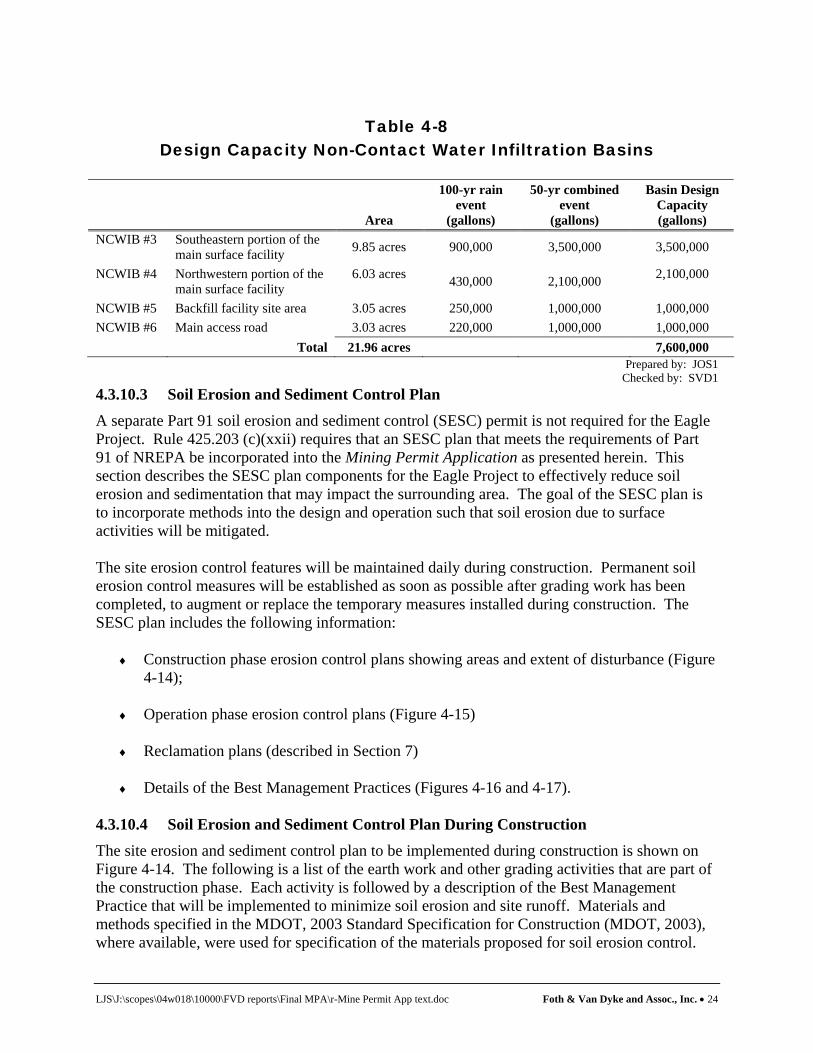
LJS\J:\scopes\04w018\10000\FVD reports\Final MPA\r-Mine Permit App text.doc Foth & Van Dyke and Assoc., Inc. • 24
Table 4-8
Design Capacity Non-Contact Water Infiltration Basins
Area
100-yr rain event
(gallons)
50-yr combined event
(gallons)
Basin Design Capacity (gallons)
NCWIB #3 Southeastern portion of the main surface facility 9.85 acres 900,000 3,500,000 3,500,000
NCWIB #4 Northwestern portion of the main surface facility
6.03 acres 430,000 2,100,000 2,100,000
NCWIB #5 Backfill facility site area 3.05 acres 250,000 1,000,000 1,000,000 NCWIB #6 Main access road 3.03 acres 220,000 1,000,000 1,000,000 Total 21.96 acres 7,600,000
Prepared by: JOS1 Checked by: SVD1
4.3.10.3 Soil Erosion and Sediment Control Plan A separate Part 91 soil erosion and sediment control (SESC) permit is not required for the Eagle Project. Rule 425.203 (c)(xxii) requires that an SESC plan that meets the requirements of Part 91 of NREPA be incorporated into the Mining Permit Application as presented herein. This section describes the SESC plan components for the Eagle Project to effectively reduce soil erosion and sedimentation that may impact the surrounding area. The goal of the SESC plan is to incorporate methods into the design and operation such that soil erosion due to surface activities will be mitigated. The site erosion control features will be maintained daily during construction. Permanent soil erosion control measures will be established as soon as possible after grading work has been completed, to augment or replace the temporary measures installed during construction. The SESC plan includes the following information:
♦ Construction phase erosion control plans showing areas and extent of disturbance (Figure 4-14);
♦ Operation phase erosion control plans (Figure 4-15)
♦ Reclamation plans (described in Section 7)
♦ Details of the Best Management Practices (Figures 4-16 and 4-17).
4.3.10.4 Soil Erosion and Sediment Control Plan During Construction The site erosion and sediment control plan to be implemented during construction is shown on Figure 4-14. The following is a list of the earth work and other grading activities that are part of the construction phase. Each activity is followed by a description of the Best Management Practice that will be implemented to minimize soil erosion and site runoff. Materials and methods specified in the MDOT, 2003 Standard Specification for Construction (MDOT, 2003), where available, were used for specification of the materials proposed for soil erosion control.

LJS\J:\scopes\04w018\10000\FVD reports\Final MPA\r-Mine Permit App text.doc Foth & Van Dyke and Assoc., Inc. • 25
KEMC staff will be certified as construction and industrial storm water operators to complete the required inspections and coordinate repairs and maintenance during construction. Surface Water Diversion - Diversion of surface water run-on to the mine site surface facilities will not be necessary since areas around the surface facilities are generally very flat with slopes less than 0.5%. In addition, the subsoils are clean sands that have a high infiltration rate which will limit run-on. Land Clearing - Land clearing is the removal of woody and herbaceous plant material and consists of two components: clearing which is the cutting and removal of trees and grubbing which is the removal of stumps and roots. Marketable timber will be removed from the site and sold. Unmarketable timber, herbaceous plants, dead wood, stumps and other vegetation will be chipped and stockpiled on-site for use in reclamation. Stumps that are too large to be chipped will be stockpiled and burned on-site. The soil and erosion control practices that are proposed include:
♦ Clearing marketable and non-marketable trees;
♦ Completing the grubbing and removal of tree harvesting remains in a single operation to minimize disturbance; and,
♦ Construction of silt fence downgradient of the areas to be cleared and grubbed prior to
the start of earth disturbance. Refer to Figure 4-14 for the approximate locations where silt fence will be installed. Details of erosion control methods are provided on Figure 4-16 and 4-17.
Topsoil Stripping and Stockpiling - Following land clearing and grubbing, topsoil will be stripped from the mine site area as shown on Figure 4-14. Topsoil is defined as the A-horizon of the soil in which organic matter accumulates. The topsoil thickness over the mine site is typically less than three inches thick and is non-existent at many locations. A 3-inch thickness has been used to size the topsoil stockpiles. Prior to stripping the topsoil additional silt fence will be constructed downgradient of the disturbed areas. Topsoil and any excess soil will be stockpiled in the previously prepared stockpile area with maximum side-slopes of 3 horizontal to 1 vertical (3H:1V). Silt fence will also be constructed around the soil stockpiles. Topsoil and excess soil will be stockpiled with conventional earth-moving equipment. Prior to seeding, the stockpile soil surface will be “track walked” (i.e. driving a bulldozer up and down the slope to leave a pattern of track imprints parallel to the slope contours) to create a rough surface. This rough surface will enhance the ability of the soil to withstand erosion until vegetation has developed. The stockpiles will be seeded with a mixture typically used on sandy soil for roadside restoration projects as specified in the MDOT, 2003 Standard Specifications for Construction (MDOT, 2003). Seed mixtures will include temporary species such as oats or perennial rye grass that germinate quickly and act as a nurse crop until the perennial species germinate and develop. Site Excavation and Grading - The site will be rough-graded to the grades as shown on Figure 4-6, prior to excavation of the TDRSA, NCWIBs and CWBs. As part of the final site grading design, diversion berms and ditching will be used to separate the main operations and non-

LJS\J:\scopes\04w018\10000\FVD reports\Final MPA\r-Mine Permit App text.doc Foth & Van Dyke and Assoc., Inc. • 26
contact areas. Excess soil will be used to build berms around the facility as shown on Figure 4-15. Once the surface facilities are under construction, disturbed areas will be seeded as soon as possible. 4.3.10.5 Soil Erosion and Sediment Control Plan During Operations The site erosion control and sediment control to be implemented during operations is shown on Figure 4-15. Once the surface facilities are constructed and vegetation has been re-established, the main component of the SESC plan will be to maintain the storm water conveyance and storage basins as designed and constructed. This will require regular inspections after precipitation or snow melt events. Areas that show erosion or rutting will be repaired as soon as practical by filling with topsoil and seeding, as described in the previous section. The NCWIBs will be inspected for siltation which could reduce the infiltration capacity of the basins. Planned operation and maintenance activities for the facility storm water and erosion control structures are listed in the table provided on Figure 4-15. This includes maintenance and repair of the storm water conveyance system and erosion control features described above during construction. KEMC will designate one of the technical staff to be a certified storm water operator to complete the regular inspections and coordinate repairs or maintenance during operations. 4.3.11 Site Utilities The site utilities for the Eagle Project surface facilities will include electrical, heating, telephone, water and sanitary systems. A utility water system will be provided for operation needs including the crusher system and underground drilling equipment, etc. A fire water system will also be provided that will distribute water to the mine and surface facilities at designated locations for fire protection. 4.3.11.1 Electric Service Facility electric power is provided by a set of three diesel generators, each capable of delivering 1825 kW of power. Each generator will be equipped with selective catalytic reduction (SCR) units installed on individual exhaust stacks. SCR units will reduce the concentration of NOx in the generator exhaust. Three generators will be provided, however, only two will be operating at all times. This provides redundancy and regular periods of downtime for maintenance. The generators will be operated equally throughout the year with equal loading, barring malfunction. The maximum routine power needed during full mine operation will be approximately 2.63 mW. The generators will be fueled with No. 2 diesel fuel with a sulfur content of less than 0.5%. The electrical distribution system will provide power to the main surface facilities, the backfill surface facilities, the potable well, and underground facilities. 4.3.11.2 Mine and Surface Facilities Heating
Captured generator exhaust heat will heat the portal to a temperature above 32° F. Four propane heaters having a combined capacity of 16,000,000 Btu/hr will also be provided to augment heating needs to keep the portal above 32°F. Combustion by-products from the propane heaters

LJS\J:\scopes\04w018\10000\FVD reports\Final MPA\r-Mine Permit App text.doc Foth & Van Dyke and Assoc., Inc. • 27
will be vented through stacks or will be directly vented into the mine through duct work to the portal. Electrical base board heaters will be provided in office spaces and other surface facilities requiring heat. 4.3.11.3 Telephone Service Currently, landline telephone service is not available to the Eagle Project site. During all phases of the project, communications will be provided through the use of satellite telephones or other means. A separate communication system will be provided for underground operations employing a base station with a multi-channel system for both voice and data communication. 4.3.11.4 Potable Water A potable water system will be provided to supply potable water to the site buildings, the lab, and to the mine. A well, pump, potable water tank, and distribution system will be provided for potable water. KEMC plans to use well QAL011D (see Figure 4-1) as a potable well for the project and will apply for a Type II Non-Transient Non-Community Water Supply Permit from the Marquette County Health Department. 4.3.11.5 Sanitary System The Eagle Project on-site septic system (OSS) is designed based upon expected operation loading and will be permitted through the Marquette County Health Department. The design flow for the OSS is based on the number of employees. From Table 4-2, the total project employment will be 110. From Table 1 of the Michigan Criteria for Subsurface Sewage Disposal, the design flow for an employee at an industrial facility is approximately 35 gallons per day (gpd). Therefore, the peak design flow based upon the State of Michigan criteria for the OSS is 3,850 gpd. The OSS includes the following components as discussed below:
♦ Septic tank ♦ Dosing pumps ♦ Soil absorption system
The septic tank system will provide a total of 4,000 gallons capacity. The volume will be split into 2 or 3 tanks or compartments. The first compartment will be a minimum of 2,000 gallons. The multiple compartment design will provide improved solids separation and treatment. The design flow for the OSS exceeds 2,000 gpd and as such is required by state code to use dosing pumps for septic tank effluent distribution. Therefore, two dosing pumps will be provided to operate on an alternating basis. The dosing pumps will be located in a separate tank with septic tank effluent flowing into the dosing tank. The soil absorption system will consist of distribution piping placed in a shallow gravel trench. The trench width will be three feet and the trenches will be spaced with four feet between the

LJS\J:\scopes\04w018\10000\FVD reports\Final MPA\r-Mine Permit App text.doc Foth & Van Dyke and Assoc., Inc. • 28
trench walls. The distribution piping will be 1.5-in. diameter PVC or HDPE pipe with perforations typically five feet apart. The dosing pumps will provide adequate pressure to force equal flow through each perforation. The infiltration rate of site soils has been measured as approximately 60 ft/d (Foth & Van Dyke, 2006). The loading rate (gpd/ft2) is determined based on soil types. Based upon the Michigan Criteria for Subsurface Sewage Disposal Section IX, C, 5 the design loading rate for this type of soil is 0.5 gpd/ft2. The area required for a design flow rate of 3,850 gpd is 7,700 ft2 of trench. With trenches three feet wide and spaced four feet between trenches, the total area required for soil absorption is 18,000 ft2. Additional space is needed for the septic tanks and dosing pump chamber. The distribution system will be designed with three cells. Each cell will have a shut-off valve to allow one cell to rest or be repaired while the other cells are in operation. A reserve area is required to provide a replacement of the soil absorption system without using the initial system. Figure 4-2 shows the location at the OSS. The area identified for the OSS is adequate for the initial soil absorption system and, if necessary, replacement of the soil absorption system. During initial site development, the construction contractor will be responsible for providing temporary facilities during construction until the OSS system and the sanitary sewer piping to the OSS is operational. During the mine operation the septic tanks will be pumped on an annual basis to remove excess solids. The dosing pumps will be inspected and maintained on a regular basis. The distribution system will be inspected several times during the year and cells rested each year. This system along with routine maintenance will provide effective sanitary wastewater treatment and disposal at the mine site. 4.3.12 Water Usage, Treatment and Discharge The Eagle Project will have an extensive water management program. Figure 4-2 shows the locations of the main water management facilities including the CWBs, the WWTP, and the TWIS. Water requiring treatment will be generated during construction, operation, and closure of the Eagle Project. Each of the major sources of mine water is discussed in more detail below. The design of the facilities to be used for collection, treatment, and disposal of these wastewaters is also discussed below. A more detailed description of the water sources and treatment and discharge systems is provided in the Groundwater Discharge Permit Application (Foth & Van Dyke, 2006). 4.3.12.1 Wastewater Sources and Characteristics The following is a summary of the different wastewater sources that will be treated by the WWTP. Mine Drainage - Sources of water inflow to the mine will include groundwater infiltration into the mine, water vapor contained in ventilation air entering the mine, treated water pumped to the mine for use in mining operations, and water contained in the mine backfill material.

LJS\J:\scopes\04w018\10000\FVD reports\Final MPA\r-Mine Permit App text.doc Foth & Van Dyke and Assoc., Inc. • 29
The mine drainage water will primarily consist of a composite of groundwater that infiltrates into the mine and treated water used in the mine (utility water) for dust suppression and for operation of mining equipment and operating the backfill plant. Drainage from the mine backfill material is anticipated to be negligible and is not included in the water balance. The mine drainage water will be collected in underground sumps and will be pumped to the CWBs. Two sources of groundwater are anticipated to be encountered during development and operation of the mine. The primary source will be groundwater that flows from the upper bedrock regions into the upper mining levels. The upper bedrock water that is expected to be encountered during both the mine development and mine operation phases, will represent the bulk of the water pumped from the mine and is low in total dissolved solids (TDS). The second source of groundwater is water that is stored within the weakly connected fractures of the lower bedrock and which is expected to be encountered during initial development when the stored water in the rock drains to the mine sumps. The deeper bedrock water is more saline than the upper bedrock groundwater. The chemical characteristics of the groundwater in the area of the Eagle Project were estimated based on background groundwater sampling and analysis work conducted by Golder Associates, Ltd. (2005b) and Golder Associates, Inc. (2006). Analysis of groundwater samples from exploration holes open to the upper bedrock and yielding non-saline water were used to determine the chemical characteristics for the upper bedrock groundwater. Groundwater samples from testing of deep exploration holes were used to determine the chemical characteristics of the water stored in fractures of the deeper bedrock. The chemical characteristics of the composite mine drainage water will depend on the background characteristics of the groundwater that infiltrates into the mine and on the impact of groundwater contact with the mine workings. The mine drainage water will contain readily soluble substances, mineral oxidation products, and colloidal materials that will result from the short-term reactions between water and materials within the mine. The incremental increases in the concentrations of the various constituents in the groundwater infiltrating into the mine, due to contact with the mine workings, are provided in Appendix D-4. The Groundwater Discharge Permit Application (Foth & Van Dyke, 2006) describes the methodology for combining background bedrock groundwater quality data and geochemical predictions to estimate the chemical characteristics of the mine drainage water pumped from the mine during operations. Although ammonia and nitrates are not anticipated to occur in the groundwater in significant concentrations, they will be present in the mine drainage water as byproducts from blasting operations. Ammonia and nitrate concentrations in the mine drainage water were estimated based on information supplied by Kennecott from other representative mines. The estimated mine drainage water characteristics are provided in Table 4-1 of the Groundwater Discharge Permit Application (Foth & Van Dyke, 2006). Temporary Development Rock Storage Area - Water coming in contact with the stored development rock amended with limestone may contain readily soluble substances and colloidal materials. The water will have a neutral pH. The chemical characteristics of the TDRSA contact water are provided in Appendix D. The geomembrane cover which will be installed over the TDRSA will further reduce the generation of contact water requiring treatment.

LJS\J:\scopes\04w018\10000\FVD reports\Final MPA\r-Mine Permit App text.doc Foth & Van Dyke and Assoc., Inc. • 30
Storm Water - During construction and operation of the mine and surface facilities, storm water runoff will be collected and managed within the facility. The storm water runoff from the operational area will be collected in the CWBs and treated at the WWTP. Non-contact surface water runoff will be managed separately by NCWIBs and is not part of the influent water to the WWTP. For WWTP design purposes, operational surface water runoff from the main operations area was conservatively estimated to have the same water chemistry as the combined contact water (mine drainage water and TDRSA contact water). Miscellaneous Sources of Wastewater - Wastewater will also be generated from the laboratory and shops. The wastewater generated in the laboratory will include small amounts of laboratory chemicals used in ore analysis and in analysis of wastewaters. Wastes generated in the laboratories will be disposed off-site by a qualified contractor or will be discharged to the CWBs and processed. Wastewater generated in the shops will include small amounts of grease and oil, metal shavings, other particulate materials, and wash water. Most of the grease will be captured in traps. These wastewaters will be discharged to the CWBs and treated by the WWTP. Small quantities of wastewater from the truck wash and crusher system will also be discharged to the CWBs and treated by the WWTP. 4.3.12.2 Water Balance Two water balance models have been prepared for the Eagle Project. The first water balance model (Figure 4-18A) evaluates the system water balance based upon the design basis groundwater inflow and maximum annual precipitation. For WWTP design purposes a design basis of 250 gpm of groundwater inflow was assumed. This design basis exceeds the upper bound groundwater inflow estimated of 215 gpm. The groundwater inflow modeling is provided in the EIA in Volume II of this Mining Permit Application. The second water balance model (Figure 4-18B) evaluates the system water balance using expected groundwater inflow (75 gpm) and average annual precipitation. The water balance determines the water inputs, water uses, and water discharges associated with the mine and the main operations area. Potable water for sanitary uses will be obtained from an on-site well. Sanitary wastewater will be collected and disposed separately in a septic system. The Groundwater Discharge Permit Application (Foth & Van Dyke, 2006) contains additional discussions on the design basis of the WWTP and the development of the water balances in Figures 4-18A and 4-18B. 4.3.12.3 Wastewater Treatment System The WWTP will treat wastewater collected and stored in the CWBs and is designed to produce a treated effluent which will meet the effluent standards for discharge to groundwater by way of the TWIS. The WWTP will be designed to provide a level of treatment to comply with MDEQ groundwater quality standards.

LJS\J:\scopes\04w018\10000\FVD reports\Final MPA\r-Mine Permit App text.doc Foth & Van Dyke and Assoc., Inc. • 31
The water treatment system includes the following processes:
♦ CWBs ♦ Main wastewater treatment process ♦ Concentrate reduction process ♦ Evaporation/Crystallization process ♦ Sludge handling process ♦ TWIS
Detailed descriptions of these processes are provided in the Groundwater Discharge Permit Application (Foth & Van Dyke, 2006). All wastewater generated at the Eagle Project, with the exception of sanitary wastewater, will be routed to, and temporarily stored in CWBs No.1 and No.2. Appendix E provides the design capacity of the CWBs. A cross section and details of the CWBs are shown on Figure 4-19. These basins will provide wastewater storage and equalization capacity. Wastewater will be pumped from these basins to the WWTP. The main wastewater treatment process will include a base treatment system and an advanced treatment system. The base treatment system will include pH adjustment, metals precipitation, and filtration to substantially reduce the mass of dissolved solids present in the raw wastewater. The advanced treatment system will include a reverse osmosis system and pH adjustment as a polishing step to further reduce the concentrations of dissolved solids in the base treatment system effluent. The discharge streams from the final wastewater treatment process will include treated water, metals precipitation sludge, and reverse osmosis concentrate. The treated water will be suitable for discharge to groundwater the TWIS. The TWIS consists of series of distribution piping connecting to five subsurface infiltration cells. Within each infiltration cell will be 1.5-in diameter perforated PVC discharge piping covered with 5 ft of select soils, then topsoiled and seeded. The metals precipitation sludge will be routed to the sludge handling process for dewatering. The reverse osmosis concentrate will be routed to the concentrate reduction process (CRP) for treatment and volume reduction. The CRP will be provided to maximize the water recovery for the WWTP and correspondingly minimize the volume of concentrate treated by the evaporator/crystallizer process. The CRP will treat the concentrate from the main wastewater treatment process reverse osmosis system. The treatment processes proposed for this system include breakpoint chlorination, softening/metals precipitation, microfiltration, pH adjustment, reverse osmosis, and ion exchange. The discharge streams from the concentrate reduction process will include treated water, microfiltration sludge, and reverse osmosis concentrate. The treated water will be suitable for discharge to groundwater by way of the TWIS. The microfiltration sludge will be routed to the sludge handling process for dewatering. The reverse osmosis concentrate will be routed to an evaporation/crystallization process for volume reduction or incorporated with the cemented mine backfill. The sludge handling process will dewater sludge from the main wastewater treatment process metals precipitation/sedimentation system and sludge from the concentrate reduction process microfiltration system. A plate and frame filter press will be used for sludge dewatering. Filtrate from the filter press will be routed back to the head end of the concentrate reduction process for

LJS\J:\scopes\04w018\10000\FVD reports\Final MPA\r-Mine Permit App text.doc Foth & Van Dyke and Assoc., Inc. • 32
treatment. The dewatered sludge from the filter press will be will be managed in accordance with applicable regulations. During periods when cemented backfill is not generated, the evaporation/crystallization process is provided for volume reduction of the reverse osmosis concentrate from the CRP. Distillate from the evaporator will be discharged though the TWIS along with treated water from the main wastewater treatment process. Brine solids from the crystallizer will be managed in accordance with applicable regulations. 4.3.13 Backfill Aggregate Stockpiles The backfill aggregate stockpile area located near the backfill raise is shown on Figure 4-2. Also present near the aggregate stockpile and backfill raise will be a 110-tonne capacity fly ash silo, and a 110-tonne capacity cement silo. During full production it is estimated that approximately 200 tonnes per day of aggregate will be required for mine backfilling operations. Clean aggregate will be supplied from a local vendor. Aggregate from the stockpile will be moved via front-end loader to the aggregate hopper feeding the 2.4 m (~8 ft) diameter aggregate raise. Surface water drainage from the aggregate stockpiles will be controlled via perimeter ditching, draining to NCWIB #5 as shown on Figure 4-2. 4.3.14 Security and Access Control Security and access control will be maintained at all times at the Eagle Project. Surrounding the facility will be an 8-foot high chain link fence. Access to the facility will only be allowed via the main facility entrance off Triple A Road. Vehicles entering or leaving the facility must pass through the main gate. An attendant will be present at the gate house to control facility entry. In addition, the excess soil berm constructed around the facility boundary will also limit unauthorized access. 4.3.15 Aesthetics and Landscaping The Eagle Project will be naturally obscured by the existing trees and the rock outcrop at the main surface facility. In addition, a berm of excess soil will be placed directly around the boundary of the facility to limit visibility of the site. KEMC may selectively plant trees to further obscure the mine facilities from Triple A Road. Near the entrance road landscaping will blend with the natural flora to develop a balanced natural appearance. 4.3.16 Fuel Handling and Chemical Storage Fuel handling at the facility will include diesel to power the generators, regular unleaded gasoline for light equipment and propane for heating. The fuel storage facility will be located within the fenced and secured area shown on Figure 4-2, and will contain three diesel fuel storage tanks each having an approximate capacity of 20,000 gallons (for a total of 60,000 gallons) located within a roofed secondary containment system. One smaller tank for regular unleaded gasoline will also be provided within the containment area. Leak testing of the tanks will be conducted by the vendor upon installation to verify tank tightness. Diesel-fueled generators to supply facility electric power will be located south of the fuel storage tanks. Propane storage of an approximate capacity of 24,000 gallons will be located within the

LJS\J:\scopes\04w018\10000\FVD reports\Final MPA\r-Mine Permit App text.doc Foth & Van Dyke and Assoc., Inc. • 33
secure area of the mine property adjacent to a building that will contain a propane-fired air heating system for the mine. Fuel truck unloading will be conducted on a concrete or asphalt pad with spill protection provisions consisting of a small catch basin which drains into the secondary containment area via double walled piping. The unloading pad area will be roofed to minimize collection and treatment of precipitation. Underground fuel lines from the storage tanks that feed the electrical generators will be double walled with leak detection provisions. A discussion of the SPCC Plan is provided below. It is anticipated that diesel fuel consumption will be approximately 5,000 gallons per day. It is expected that 6 tanker trucks or approximately 30,000 gallons of diesel fuel will be delivered each week to the site. The fuel tanks will be designed in compliance with all federal, state and local requirements. A designated fueling station will be established for fueling underground vehicles using a tanker vehicle. 4.3.17 Blasting Materials Handling and Storage The blasting and cap magazine buildings will be located at a secure location within the mine facility. The blasting and cap magazine buildings will be constructed of reinforced concrete following Mining Safety and Health Administration (MSHA) requirements. The building will have explosion proof air handling and moisture control systems. Entry into these buildings will only be allowed by certified blasting material handlers. KEMC will obtain a permit from the Bureau of Alcohol, Tobacco and Fire Arms for storage and use of the explosives for the project. 4.3.18 Spill Prevention and Countermeasures Plan A SPCC Plan will be prepared for the fuel storage area that will incorporate the provisions set forth in 40 CFR 112. The SPCC Plan will be prepared prior to the commencement of operations at the facility. The SPCC Plan will be reviewed and certified by a Professional Engineer, maintained at the facility and reviewed and revised as required by federal, state, and local regulations. Pursuant to the SPCC Plan and regulatory requirements, tanks and secondary containment will be designed to contain a potential spill. Storage tanks and containment areas will also be installed such that prevention measures for all fuel handling and storage are incorporated into the design, including techniques that will be used to contain potential spills during loading and off-loading of vehicles. In addition to the federal SPCC requirements, all aboveground storage tanks containing flammable or combustible materials must be in compliance with the Michigan Fire Prevention Code statute at 1941 PA 207. The statute applies not only to tanks that store liquid petroleum products, but also to storage of compressed gases, including propane. Design plans for affected storage tanks will be submitted to the MDEQ Waste and Hazardous Materials Division for approval. In addition to the above requirements, the facility will also comply with R 324.2001 through 2009. These rules require preparation of a PIPP to address potential spillage of fuel, salt and other “polluting materials” listed under Rule 324.2009. While a portion of these rules contain requirements that are similar to the federal SPCC rules, the regulations also contain requirements to cover salt and any listed “polluting material” that is above indicated Threshold Reporting Quantities. The listed materials include numerous metal compounds, including copper and nickel. The rules state that if these materials are in solid form, they shall be stored such that they

LJS\J:\scopes\04w018\10000\FVD reports\Final MPA\r-Mine Permit App text.doc Foth & Van Dyke and Assoc., Inc. • 34
are “enclosed, covered, contained or otherwise protected to prevent run-on and runoff”. Design provisions for all storage facilities at the site contain adequate measures to meet this requirement. To ensure that an overall cohesive spill prevention and pollution control plan is prepared for the site, it is anticipated that the PIPP will incorporate all requirements of the SPCC Plan as well as requirements for other regulated chemicals at the site. The PIPP will be prepared prior to commencement of operations at the site. Once the written PIPP is prepared, notice will be provided to the state and other emergency agencies that the PIPP is available. The PIPP will then be provided upon request. In accordance with state regulations, the PIPP will be reviewed every 3 years. 4.4 Underground Mine Description
The basic design concept for the underground mine will be to employ transverse blasthole stoping with blind benching. The mine design is based upon extracting 2,000 tonnes per day of ore. Total mineable reserves are approximately 3,419,453 tonnes. An overall section of the mine is shown in Figure 4-5. 4.4.1 Mine Design and Layout The mine design is based upon 10 production levels as shown on Figure 4-5. Mining will progress from mine level 143 m upward to mine level 353 m. Mine level 383 m will be selectively mined based upon further geotechnical analysis conducted on the crown pillar as mining progresses upward. The geotechnical analysis conducted by Golder Associates has determined that the proposed mining plan will be stable. A copy of the Golder Associates geotechnical reports are provided in Appendix C. Additional geotechnical analysis will be conducted as part of continuous rock mass assessment performed during each level development. The mine design is based upon: 1) maintaining economic production levels by incorporating bulk-mining methods, and 2) preventing surface subsidence due to underground mining. The geotechnical analysis presented in Appendix C has determined there will be no measurable subsidence at ground surface due to the underground mine. A 3-dimensional schematic of the underground mine is displayed on Illustration 4-2.
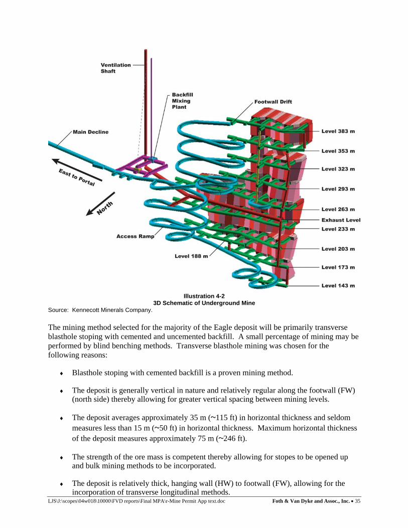
LJS\J:\scopes\04w018\10000\FVD reports\Final MPA\r-Mine Permit App text.doc Foth & Van Dyke and Assoc., Inc. • 35
Illustration 4-2 3D Schematic of Underground Mine
Source: Kennecott Minerals Company. The mining method selected for the majority of the Eagle deposit will be primarily transverse blasthole stoping with cemented and uncemented backfill. A small percentage of mining may be performed by blind benching methods. Transverse blasthole mining was chosen for the following reasons:
♦ Blasthole stoping with cemented backfill is a proven mining method. ♦ The deposit is generally vertical in nature and relatively regular along the footwall (FW)
(north side) thereby allowing for greater vertical spacing between mining levels.
♦ The deposit averages approximately 35 m (~115 ft) in horizontal thickness and seldom measures less than 15 m (~50 ft) in horizontal thickness. Maximum horizontal thickness of the deposit measures approximately 75 m (~246 ft).
♦ The strength of the ore mass is competent thereby allowing for stopes to be opened up
and bulk mining methods to be incorporated.
♦ The deposit is relatively thick, hanging wall (HW) to footwall (FW), allowing for the incorporation of transverse longitudinal methods.

LJS\J:\scopes\04w018\10000\FVD reports\Final MPA\r-Mine Permit App text.doc Foth & Van Dyke and Assoc., Inc. • 36
♦ There is an availability of backfill material on-site for use in secondary stopes for
uncemented backfill. 4.4.2 Mine Access The mine design includes the following access developments:
♦ Portal ♦ Main Decline ♦ Footwall Drift ♦ Emergency Escape
Construction of these developments may employ the use of cement and bentonite based grout for localized control of water inflow to the mine workings. Portal The portal facility is located on the west side of the bedrock outcrop shown in Figure 4-2. The portal will be constructed with steel arches having a 7.2 m (~24 ft) span and 5.8 m (~19 ft) rise. The steel arch sets will extend out from the rock face approximately 37.0 m (~121 ft). The rock cut will be backfilled with compacted engineered fill after the steel plates are set. A concrete headwall will secure the steel arch plates into the bedrock. Details of the portal are shown on Figure 4-7. Main Decline Mine access is gained through the main decline. The decline will be at 5.5 m (~18 ft) wide by 5.0 m (~16 ft) high sloped 15.0% for 120 m (~39 ft) then reduced to -12.0%. The decline is slightly steeper initially in order to quickly access the bedrock thereby minimizing the volume of alluvium excavated and required support. Dimensions of the main decline are based on clearance criteria of the low profile production haul trucks as well as maximum ventilation velocities in the decline. Footwall Drift FW drifts will measure 4.5 m (~15 ft) wide by 4.5 m (~15 ft) high. The largest equipment expected to enter the FW drifts are the 5.4 m3 (~7 yd3) production LHDs. FW development is designed to maintain a minimum 20 m (~66 ft) offset from the stope FW. The FW drift provides access to the transverse blasthole stopes, sump, mine load center, exhaust raise, etc. Emergency Escape Emergency escape will be provided by an elevator installed in the main exhaust raise. The bottom of the elevator is located at mine level 248 m and exits the raise on surface at an air lock-off the exhaust fan housing. The elevator is installed on the wall of the raise. The elevator, shown in Figure 4-12, has a design capacity of 545 kg or approximately 5-6 persons. A manway will also be installed in the return air raise between mining levels. The manway will have platforms spaced every 7.0 m (~23 ft). The emergency escape routes are shown on Illustration 4-3.

LJS\J:\scopes\04w018\10000\FVD reports\Final MPA\r-Mine Permit App text.doc Foth & Van Dyke and Assoc., Inc. • 37
Illustration 4-3
Emergency Escape Routes Source: Adapted from McIntosh Engineers 4.4.3 Transverse Blasthole Stoping Two sizes of transverse stopes were developed, 30 m (~98 ft) high (sill to sill) and 15 m (~49 ft) high (sill to sill). All transverse stopes measure 10 m (~33 ft) wide, regardless of their height. The 30 m (~98 ft) high stopes have lengths, (HW to FW) ranging from approximately 15 m (~49 ft) to 70 m (~230 ft). The 15 m (~49 ft) high stopes have lengths (HW to FW) ranging from approximately 15 m (~49 ft) to 40 m (~131 ft). The 15 m (~49 ft) high stopes were designed to increase recovery. Each stope includes a top cut (or drill level) at the top of the stope and an undercut (or production level) at the bottom. Top cut and undercut levels are developed by drifting from the FW to the HW, then slashing the stope to the full 10 m (~33 ft) width. Actual stope limits will be identified by stope definition drilling and sampling programs during operations. Current stope designs have both HW and FW planes that best follow the ore body within the capabilities of the production drills. This allows for the design of inclined HW and FW stope limits, thereby reducing waste and increasing ore recovery. Once stope development is complete, a slot raise is developed. Slot raise cut holes are planned at 0.76 m (~30 in) in diameter, then opened up to 2.4 m (~8 ft) by 2.4 m (~8 ft). Smaller diameter slot raise cut holes are developed using the 115 mm (~4.5 in) production drill blast holes. The slot is drilled and shot in a two-row blast to the full 10 m width of the stope. The slot is designed at 4.5 m (~15 ft) long HW to FW. Illustration 4-4 shows this sequence for a typical 30 m (~98 ft) stope.

LJS\J:\scopes\04w018\10000\FVD reports\Final MPA\r-Mine Permit App text.doc Foth & Van Dyke and Assoc., Inc. • 38
Illustration 4-4 Typical Stope Development Plan
Source: Adapted from McIntosh Engineers 4.4.4 Production Drilling and Blasting
4.4.4.1 Production Drilling Production drilling will be performed by track-mounted drill rigs capable of drilling 89 mm (~3.5 in) to 165 mm (~6.5 in) diameter holes up to 100 m (~328 in) in length. The drills are powered using high pressure air. Typical production drilling will have the drill holes staggered in a diamond pattern alternating between four holes and three holes per row. Blasthole burden and spacing distances are estimated to be approximately 2.3 m (~7.5 ft) and 3.0 m (~9.7 ft), respectively. 4.4.4.2 Production Blasting
Production blasting will be accomplished using emulsions produced and delivered by a local explosive supplier. The maximum explosive density that can be used in 115 mm (~4.5 in) holes is 1.27 g/cc. Based upon the burden and spacing design, blasthole powder density will be 1.2 g/cc. The ability to use a higher density explosive in the future could allow for expanding the drilling pattern and therefore ultimately reducing the cost per tonne of drilling by reducing the number of holes drilled. As an alternative to emulsion, ANFO can be used. KEMC crews will perform production emulsion loading. All loading will be performed using a bulk emulsion loading system. 4.4.5 Level Development and Stope Sequence As shown on Figure 4-5 the Eagle Project will be developed with 10 levels. Figures 4-20 through 4-30 illustrate plan views of each level development. As discussed in Section 4.4.1,

LJS\J:\scopes\04w018\10000\FVD reports\Final MPA\r-Mine Permit App text.doc Foth & Van Dyke and Assoc., Inc. • 39
mine level 383 m will be selectively mined based upon further geotechnical analysis of the crown pillar and evaluation of the appropriate mining method. Level development will begin at the lowest mining levels, progressing vertically to the upper levels. Initial production is scheduled to start on mine level 143 m and mine level 173 m. Mining during the first three and a half years will be limited to production at or below mine level 263 m. Upper mine levels will be brought on line once production below mine level 263 m declines. The mining method entails development of primary and secondary stopes. A series of four-panel production units are designed to mine 10 m (~33 ft) wide by 30 m (~98 ft) high transverse stopes with minimum ground support. The stoping sequence is illustrated in Figure 4-31. The primary stopes will be filled with engineered cemented aggregate backfill prior to mining the secondary stopes. Once the primary stopes are backfilled, mining the secondary stopes will commence. Secondary stopes will be backfilled with uncemented limestone-amended development rock. Production stopes within each level were designed to sustain a consistent production rate of 2,000 t/d once full production is achieved. The production of each of the active stopes is estimated to be 500 t/d to meet the total 2,000 t/d nominal production. Production is expected to begin in year 2, with two active stopes in production during the ramp-up period. Full production will be achieved in the middle of year three when two additional active stopes are brought on line. The production rate of 2,000 t/d will be sustained until the third quarter of year nine. Production at the Eagle Project is expected to be completed near the end of year nine. 4.5 Underground Facilities
Underground facilities to support the KEMC Eagle Project will include:
♦ Mine dewatering system, ♦ Ventilation and air heating systems, ♦ Communication system, ♦ Ore hauling system, ♦ Sanitation system, ♦ Electrical system, ♦ Compressed air system, and ♦ Emergency escape, and ♦ Emergency safe room with oxygen supplied, food and water.
The facilities are discussed in further detail in the following sections. 4.5.1 Mine Dewatering System The mine dewatering system for the Eagle Project is designed to support a total of 600 gpm of pumping requirements during full production. Note that 600 gpm is not the rate of groundwater inflow to the mine. Based upon groundwater modeling the upper bound estimate of groundwater inflow is approximately 215 gpm. The groundwater inflow coupled with approximate operating service requirements results in a 600 gpm mine water pumping system.

LJS\J:\scopes\04w018\10000\FVD reports\Final MPA\r-Mine Permit App text.doc Foth & Van Dyke and Assoc., Inc. • 40
The following Illustration 4-5 shows the dewatering system flow plan. Three main dewatering pump stations are included in the dewatering system design, one located near the mine bottom, the second at mine level 173 m, and the third at the main decline at mine level 300 m. The level 173 pump station will service the development requirements until the lower station (level 143 m) has been installed. The mine level 143 m pump station will be equipped with two 58-hp pumps to pump groundwater to mine level 173 m. At mine level 173 m, two 125-hp pumps will be installed with a 10,000-gallon agitator tank. From mine level 173 m, water will be pumped to the 300 m level pump station also employing two 125 hp pumps with an agitator tank. From mine level 300 m, water will be pumped to the surface CWBs.
Illustration 4-5 Groundwater Dewatering System
Source: Adapted from McIntosh Engineers 4.5.2 Mine Ventilation Systems The ventilation design is based upon providing sufficient airflow to the mine workings to maintain safe working conditions. A minimum airflow of 150 cfm per underground worker was used in the design. The total estimated ventilation requirements are 427,000 cfm including employee and equipment demand. Intake air to the mine is provided via the main decline. Each mine level is ventilated from the decline to a dedicated return air raise. This system is referred to as single-pass ventilation which is well-suited for maintaining safe working conditions. Each return air raise will be connected to the exhaust drift on mine level 248 m.

LJS\J:\scopes\04w018\10000\FVD reports\Final MPA\r-Mine Permit App text.doc Foth & Van Dyke and Assoc., Inc. • 41
The 600 hp main exhaust fan will pull air (induced draft) from the main decline to each operating level to achieve the ventilation requirements. Used air is then pulled through return air raises (RAR) to the exhaust drift and then to the exhaust raise. Figure 4-32 is schematic of the overall mine ventilation system. 4.5.3 Underground Ore Handling Systems The underground ore flow process for the Eagle Project is as follows:
♦ On the lower mining levels, below and including mine level 263 m, ore will be remotely loaded from the stopes by production LHDs and delivered to low profile production trucks near the ramp access. If a production truck is not waiting to be loaded, the LHD dumps its bucket at an adjacent load bay and continues removing ore from the stope. When the truck arrives the LHD loads the truck from the loading bay.
♦ On levels above mine level 263 m, ore will be remotely loaded from the stopes by a
production LHDs and delivered to a centrally located coarse ore grizzly off the FW drift. Remotely operated LHD’s will be employed under these operational conditions to limit the operator’s presence within the recently blasted stope. The operator will be able to safely operate the LHD outside of the stope using this remote system. Ore drops down the ore pass to mine level 263 m where it loads the low profile production trucks. The ore pass grizzlies are equipped with dust covers to prevent dusting on the levels as well as short circuiting the ventilation. Dust covers are equipped with electric winches and operated remotely by the LHD operators.
♦ Once loaded, the low profile production trucks proceed up the decline to the COSA. In
the decline design, passing bays are included every 300 m (~984 ft) for vehicles and personnel to allow for the loaded trucks to pass.
♦ The COSA will have a capacity of 3,000 m3 (~3,924 yd3). The production trucks dump
their loads and proceed back underground. The underground ore handling system is based upon “best” facility economics. Because economics are constantly changing due to market conditions, changes to the underground ore handling system may be necessary to reflect future market conditions. 4.5.4 Communication Systems Communications through the mine will be accomplished using a digital cable system. At each level and at other designated locations, wireless routers will be installed. The main control will be in the dispatch center on surface. The base station is multi-channel and used for both voice and data communication. A computer will be integrated with the system to manage data communication. Data communication is for vehicle dispatch systems. Voice communication will be hand held or vehicle mounted radios. The cable system will have multiple vehicle-mounted radios. A tag reading system will be installed at critical areas to ensure all persons are accounted for within the mine. In addition, a manual tag out system will also be used.

LJS\J:\scopes\04w018\10000\FVD reports\Final MPA\r-Mine Permit App text.doc Foth & Van Dyke and Assoc., Inc. • 42
4.5.5 Sanitation Systems Underground sanitation facilities will be provided in accordance with applicable requirements and may consist of portable toilets and sinks placed at several underground locations. Toilets will be periodically brought to the surface and cleaned or exchanged by a vendor. 4.5.6 Underground Electric Supply Underground electrical demand will be provided by the three surface diesel generators. Only two generators will be running at any given time. The third generator will be used as back-up. Routine power needed during full mine operation will be approximately 2.63 mW. The largest loads for the Eagle Project will be from the exhaust raise fan, backfill plant and the dewatering pumps. Power will also be supplied to remote sites (backfill facility and potable well pump). 4.5.7 Compressed Air System Compressed air is required for support of mining activities. Compressed air will be distributed from the surface air plant to mine workings using steel pipe. Compressed air requirement for the Eagle Project is 3,600 scfm based upon a line pressure requirement for equipment at 80 to 90 psig. The connection between mining levels will consist of 150 mm (~6.0 in) pipes installed in the main access ramps. Laterals across mining levels will be 100 mm (~4 in) pipes. 4.5.8 Mine Utility Water Treated mine utility water will be supplied to both surface and underground facilities including the crusher, truck wash, drilling equipment and underground dust control equipment, etc. (see Figures 4-18A and 4-18B for water balance). 4.6 Mine Backfill
Mine backfilling will be conducted in mined out stopes concurrent with the mining of new stopes. The primary stopes will be backfilled using cemented aggregate. The secondary stopes will be backfilled either with limestone amended development rock or other aggregate fill material. The estimated amount of material for secondary backfilling is 936,419 tonnes (Table 4-4). Table 4-9 summarizes the total required primary and secondary backfill tonnage.
Table 4-9 Mine Backfill Requirements
Backfill Type Quantity (tonnes)
Primary Backfill 1,766,867
Secondary Backfill 936,419(1) Total 2,103,288
(1) Excluding 12,586 tonnes placed as underground roadbed during mine operations Adapted from McIntosh Engineering
Prepared by: JOS1 Checked by: SVD1
LJS\J:\scopes\04w018\10000\FVD reports\Final MPA\r-Mine Permit App text.doc Foth & Van Dyke and Assoc., Inc. • 43
The backfill cement plant will be located near mine level 263 m. A 2.4 m (~8 ft) diameter raise will feed the aggregate silo. The capacity of the silo is approximately 800 tonnes. If needed, aggregate will be stockpiled at the surface near the raise. Cement and fly ash storage silos will be located on the surface providing 110 tonnes of capacity each. Once the cement/fly ash is thoroughly blended, the mix will be discharged to an underground binder bin via a cased 250 mm (~10 in) diameter borehole, feeding a colloidal mixer. It is estimated that cement binder will be approximately 6% by weight. The binder mix is estimated to be a 50:50 proportion of cement and Class C fly ash. The backfill plant will include an automatic colloidal slurry mixer which feeds a continuous backfill mixer. The mixer will be positioned to allow drive-through with the 40-tonne backfill trucks. The loaded 40-tonne trucks will then take the mix to the designated stope. Figure 4-33 illustrates the backfill plant flow diagram. Water requirements for the backfill mixing process are displayed in the water balance for the project (Figures 4-18A and 4-18B). 4.6.1 Mine Stability and Subsidence Prevention Golder Associates conducted mine stability and ground surface subsidence modeling as documented in Appendix C. Both plastic and elastic deformation of the crown pillar rock mass were evaluated. Plastic deformation is defined as the collapse and subsequent unraveling and bulking of the displaced rock mass. Elastic deformation is the displacement of the rock mass by “bending” over a void space. Plastic and elastic deformation are both a function of the effectiveness of the backfilling plan. The analyses presented in Appendix C show that plastic deformation will not occur with the proposed stope backfilling plan. Plastic deformation of the crown pillar will be limited to no more than 2 cm at the bedrock/alluvial contact. Given this small displacement, movement at the ground surface will not be measurable. KEMC will conduct subsidence monitoring during operations and during the 20 year post-reclamation monitoring period. The mine decline stability was also assessed by Golder Associates and determined to be stable without backfilling. As such, backfill of the mine decline will only occur at specific locations to prevent interconnection of different groundwater regimes as described in the reclamation plan in Section 7. As needed, rock support mechanisms such as roof bolting may be employed to stabilize the decline roof at discrete locations.
LJS\J:\scopes\04w018\10000\FVD reports\Final MPA\r-Mine Permit App text.doc Foth & Van Dyke and Assoc., Inc. • 44
5 Treatment and Containment Plan for Mine Related Material This treatment and containment plan has been prepared in accordance with R 425.203(h) and R 425.409. This treatment and containment plan describes measures to prevent impacts to groundwater and surface water and applies to all reactive earthen materials. Treatment and containment facilities as part of this plan will include the TDRSA and COSA. Plans for addressing the potential for leaching of mining related constituents from the peripheral rock to the aquifer at the site is addressed in the reclamation plan for the underground mine in Section 7 and the contingency plan in Section 8. Note that the treatment and containment plan for the TDRSA and COSA as well as the reclamation of the underground mine is designed to protect groundwater in aquifers per the definition of an aquifer in R 425.102(1)(c). As such, protection of groundwater quality in the alluvial aquifer consisting of glacial outwash and till and its associated surface water systems are the design objective for the treatment and containment plan. 5.1 Temporary Development Rock Storage Area
The TDRSA is designed to temporarily store development rock generated during mine development from the decline, drifts, levels, raises and other underground workings needed to access the ore body. Table 4-4 provides a list of the quantity of development rock removed each year and temporarily stored in the TDRSA. The development rock will be hauled to the surface and placed in the TDRSA using low profile production trucks. The size of the TDRSA is based on the mine planning and operations information developed by KEMC and the geochemical analysis completed by Geochimica, Inc. (Appendix D). This information forms the basis of the design and includes the following:
♦ The TDRSA is a temporary facility that will be operated for a period of about seven years;
♦ The maximum quantity of development rock that will be stored in the TDRSA is
189,500 m3 (247,900 yd3).
♦ The development rock that is stored in the TDRSA will be amended with approximately 7,800 tonnes of high calcium limestone to:
Add additional neutralizing capacity to the TDRSA.
Reduce the concentration of pH sensitive metals in the contact water that is collected
in the contact water collection system of the TDRSA. 5.1.1 Design Objectives of the TDRSA
The primary function of the TDRSA is to provide for environmentally secure surface storage of development rock generated during the mining process until the rock can be returned to the mine as backfill. The major design objectives for the TDRSA are listed below.
♦ To design, construct and operate the facility using sound engineering practices and in compliance with the standards prescribed in R 425.203(h) and R 425.409.

LJS\J:\scopes\04w018\10000\FVD reports\Final MPA\r-Mine Permit App text.doc Foth & Van Dyke and Assoc., Inc. • 45
♦ To locate the facility to avoid impacts to wetlands and surface water bodies and achieve isolation from groundwater and protection of groundwater quality in the regional alluvial aquifer.
♦ To size the facility to accommodate excess development rock to be generated throughout
the Eagle Project life.
♦ To limit oxidation of the development rock to the extent practicable over the life of the facility with the following design features.
Treat the development rock with high-calcium limestone to reduce the potential for
development of ARD;
Design and construct the base liner system and contact water collection system to effectively contain the development rock and contact water that drains from the rock.
Cover the areas of the TDRSA that are filled to grade with a temporary geomembrane
cover to minimize development rock contact with precipitation. The location and design of the TDRSA are described below along with a discussion of the rationale for selecting each of the components. 5.1.2 Facility Location The location of the TDRSA was selected with the goals of minimizing impacts to the environment and maintaining the aesthetics of the view corridors from the Triple A Road. Figure 4-2 and 4-3 show the location of the TDRSA in relation to other site features. The following are some of the separation distances and design features regarding the facility location.
♦ The TDRSA is located in an area where groundwater in the alluvial aquifer flows northeast, away from the Salmon Trout River Main Branch.
♦ The TDRSA is located approximately 731 m (~2,400 ft) northeast of the closest surface
water body, the Salmon Trout River Main Branch;
♦ The TDRSA is located approximately 518 m (~1,700 ft) north of the closest wetland that is located south of Triple A Road.
♦ The subgrade (bottom of the proposed composite liner system) of the TDRSA is
approximately 13.7 m (~45 ft) above the groundwater in the glacial alluvium.
♦ The majority of the TDRSA is located in an existing open clear-cut area.
♦ The TDRSA is located approximately 290 m (~950 ft) north of the Triple A Road at its closest point.

LJS\J:\scopes\04w018\10000\FVD reports\Final MPA\r-Mine Permit App text.doc Foth & Van Dyke and Assoc., Inc. • 46
5.1.3 Design Volume Table 4-4 presents the volume of development rock that will be stored in the TDRSA over the nine year life of the facility. The maximum anticipated volume based on the expected mine development schedule is 189, 500 m3 (~247,900 yd3). To account for variable development rock quantities and the addition of limestone, a contingency volume of 15% is included, resulting in a design volume of 217,925 m3 (~285,000 yd3). This volume includes the limestone that will be added to the development rock. If additional volume is required the final surface slopes can be steepened without compromising the stability of the facility. The capacity of the TDRSA is the volume derived from the difference between the base grades, Figure 5-1, and the final grades, Figure 5-2. 5.1.4 Subgrade Design The TDRSA subgrade and perimeter berm are the earthen structures on which the liner and contact water collection system are placed. Figure 5-1 shows the TDRSA basegrade which is the top of the composite liner. The subgrade of the TDRSA is founded in medium dense fine to medium, medium, and medium to coarse sands with typically less than 5% passing the number 200 sieve (P200). These soils are typically poorly graded sand (SP) per the Unified Soil Classification System (USCS). The subgrade has been designed to comply with R 425.409(a)(i)(C) to limit the head on the liner (except for the leachate collection sump) to one foot or less. The base grade configuration shown on Figure 5-1 includes the following:
♦ 2% slope from the interior sideslopes to the leachate collection pipes. ♦ 0.5% slope on the leachate collection system piping to the leachate collection sump. ♦ 3:1 (H:V) inside sidewall slope to the floor.
During excavation for the TDRSA the subgrade surface will be observed by a qualified field technician. Any observed unacceptable subgrade areas will be over-excavated and reconstructed with compacted fill soil. 5.1.5 Composite Liner A composite liner system as shown on Figure 5-3 was selected for the TDRSA consisting of the components listed below from bottom to top:
♦ A prepared subgrade as described previously;
♦ A geosynthetic clay liner (GCL). The GCL consists of granular bentonite clay encased within two non-woven geotextile fabrics. The GCL is an alternative to a 3-ft thick compacted clay layer as prescribed under R 425.409(a)(i)(B). This component has a saturated hydraulic conductivity of 1 x 10⁻¹⁰ cm/sec; less than the 1 x 10⁻⁷ cm/sec prescriptive requirement for the clay liner.
♦ A 60-mil high density polyethylene (HDPE) geomembrane. A 60 mil HDPE is selected
because of its very low permeability and compatibility with contact water chemistry.

LJS\J:\scopes\04w018\10000\FVD reports\Final MPA\r-Mine Permit App text.doc Foth & Van Dyke and Assoc., Inc. • 47
5.1.5.1 Geosynthetic Clay Liner (GCL) Equivalence Pursuant to R 425.409(a)(i)(B), KEMC is proposing an alternative liner design consisting of a 60-mil HDPE geomembrane liner underlain by a GCL. A water balance model using the Hydrologic Evaluation of Landfill Performance (HELP) model evaluated the equivalency of the proposed liner design to the prescriptive liner components specified in R 425.409(a)(i)(A). Based upon the analysis presented in Appendix F, the proposed alternative design provides better protection to the environment than the prescriptive design. Based on HELP model analysis of the prescriptive requirements in R 425.409 and the alternative design proposed here, the theoretical leakage through the alternative liner design is 0.000511 inches per acre-day compared to the prescriptive liner design of 0.01022 inches per acre-day, which is 20 times less than the prescriptive design. The proposed design will also provide greater collection efficiency for contact water collection. The HELP model is an analytical tool that evaluates the theoretical water balance through the system. HELP model predicted leakage rates should only be evaluated on a comparative basis considering different liner systems. It is KEMC’s intent to design a system that will not leak. Actual experience with the use of GCLs over the last 10 years has been very favorable for such applications. The MDEQ permits the use of GCLs for municipal solid waste landfill liner systems which have a potential to be in contact with a much more concentrated mixture of chemicals. The successful use of GCLs for mining and landfill applications is well documented around the U.S. by numerous state agencies including the MDEQ solid waste staff. 5.1.5.2 Liner Stability Analysis Stability analysis of the TDRSA was conducted to evaluate the strength of the liner components for the following operational conditions.
♦ Interim filling where the TDRSA is active and filling is occurring, which results in the steepest interim slope; and,
♦ Final build-out configuration where the TDRSA is filled to its design capacity.
The analyses were conducted using the PC STABLE computer program which evaluates potential failure surfaces using limit equilibrium methods. Based upon published shear strength test results for similar liner system components (referenced in Appendix G) the analysis used a minimum interfacial friction of 18° (ø = 18º). Both random and block failure surfaces were investigated to determine the critical factor of safety. Water levels were also introduced in the analysis assuming the TDRSA under the CWBs contingency plan would temporarily store excess pretreated water. Water level elevations were assumed to be 15 ft deep (top of perimeter berm at final build-out) and 4 ft and 9 ft deep (1 ft below the top of rock work working level) for interim conditions. Results of the analysis are presented in Table 5-1.

LJS\J:\scopes\04w018\10000\FVD reports\Final MPA\r-Mine Permit App text.doc Foth & Van Dyke and Assoc., Inc. • 48
Table 5-1
Summary of TDRSA Stability Analysis
Factor of Safety w/o Water w/Water (4)
Condition Block Random Block Random Interim(1)
♦ 5’ (rock on floor)(2) 1.23 2.02 1.13 1.96 ♦ 10’ (rock on floor)(3) 1.56 1.91 1.36 1.78
Final Build-Out(4) 3.64 5.18 3.05 3.97
(1) Interim slope is 1:1 (H:V) (2) 5 ft of rock present on base having a maximum outslope differential height of 35 ft. (3) 10 ft of rock on the base having a maximum outslope differential height of 45 ft.
Prepared by: JOS1 Checked by: SVD1
The stability calculations are provided in Appendix G. Results of the analyses indicate that the TDRSA will be stable and the liner system has adequate strength under the anticipated loading conditions. Under interim conditions, to maintain a factor of safety greater than 1.1, it is recommended that at least five feet of development rock be initially placed across the base. Under this condition, the maximum interim differential height should not exceed 35 ft above the top of rock on the base. If ten feet of development rock is initially placed across the base, the differential height should not exceed 45 ft. These analyses assume the foundation soils will be stable based upon the construction practices described in Section 5.1.4. Review of data from soil borings completed within the vicinity of the TDRSA shows the subsoils generally consist of medium to medium dense sands. The relative density of these soils would relate to a shear strength (i.e. friction angle) greater than the liner system components. As such any critical failure surface would have to propagate between the liner components having lower shear strength. Stability of the liner system was also conducted during simulated operations when loaded low profile haul trucks ramp down to the TDRSA floor. Because of the weight of these vehicles, stress to the underlying liner system was evaluated to verify stable conditions. This stability analysis of the liner system was evaluated using infinite slope concept whereby the calculated factor of safety against instability is a function of the liner system resistive forces divided by the driving forces. Results of this analysis are presented Table 5-2.

LJS\J:\scopes\04w018\10000\FVD reports\Final MPA\r-Mine Permit App text.doc Foth & Van Dyke and Assoc., Inc. • 49
Table 5-2 Summary of Stability Analysis
for Liner System
Condition Factor of Safety Static Slope 2.8
Vehicle Load 2.5 Prepared by: JOS1 Checked by: SVD1
Because the calculated factor of safety exceeds a minimum allowable design factor of safety of 1.1, it is determined that the liner system below the access ramp will be stable during operations. Results of this analysis are also presented in Appendix G. Details of the access ramp are shown on Figure 5-4. 5.1.5.3 Chemical Compatibility of the TDRSA Liner System and Contact Water Chemical deterioration of TDRSA geomembrane liner due to contact water is expected to be negligible due to the benign chemistry of the contact water and due to the short design life of the facility. Unless the geomembrane has leaks, no contact water will reach the GCL. Therefore, potential modes of chemical deterioration of the liner system for the TDRSA are focused on the chemical compatibility of the TDRSA water with the bentonite material in the GCL. Analysis of the expected water chemistry of the contact water in the TDRSA filled with limestone amended development rock is provided in Appendix D-3. Considering a wide range of permeants, potential modes of deterioration of bentonite are generally associated with chemical interactions that hinder the natural swelling of the bentonite when hydrated. Chemical factors include double layer compression. This can occur from:
♦ Permeants with high electrical conductivity. ♦ Permeants with high ionic strength. ♦ Permeants with ionic exchange of sodium (the cation that promotes swelling) with
calcium or other divalent cations. Deterioration can occur with permeants of extremely high or low pH (12<pH<2). Based upon the water chemistry analysis conducted for the TDRSA contact water, pH will be neutral, around 6. However, the effect is greatly reduced when there is pre-hydration of the bentonite (Ruhl and Daniel, 1997). Chemical deterioration caused by organic solvents can occur because of dielectric modification. However, no solvents are expected in the TDRSA contact water and this effect is greatly reduced when the primary liquid is water and the organics are miscible (Shackelford 1994). Chemical compatibility of the permeant and the GCL is also highly dependent on the level of percolation expected. The level of percolation may be measured by pore volumes of flow, the volume of percolation normalized to the pore volume within the bentonite clay. The damaging effects of more aggressive permeants may occur after several pore volumes of flow. More moderate incompatibility effects, such cation exchange with moderate concentrations of calcium and other divalent metals, may require many pore volumes of flow.

LJS\J:\scopes\04w018\10000\FVD reports\Final MPA\r-Mine Permit App text.doc Foth & Van Dyke and Assoc., Inc. • 50
For the case of the proposed TDRSA contact water drainage and liner system, total theoretical percolation would not be measurable. Estimates for liner percolation and drainage system performance were developed using Visual HELP Version 2.2.0.3 (Waterloo Hydrogeologic, Inc., Waterloo, Ontario). Using conservative assumptions for the buildup of head in the drainage layer, the model outcome for total theoretical percolation over the 7-yr period of operation was 0.004 cm (0.0014 in). Assuming a bentonite-layer thickness of 0.91 cm (0.030 ft) and a total porosity of 0.75, the total theoretical percolation is less than 1/100th of a pore volume of the GCL. As such, physical characteristics of the GCL such as permeability will not be altered. Since the TDRSA water will be composed of modest concentrations of ions and is expected to have a near-neutral pH, the potential for deterioration of the liner systems is negligible. In addition, the amount of percolation is so minimal that, if there was a potential for deterioration, the deterioration of the composite liner performance is unlikely because the opportunity for permeant contact and fluid exchange is greatly limited. 5.1.6 Water Collection System Details of the contact water collection system are shown on Figure 5-5. The contact water collection system overlying the TDRSA composite liner consists of the following components:
♦ A 12-in. thick granular drainage material having a minimum hydraulic conductivity of 1x10⁻³ cm/sec.
♦ A geocomposite drainage fabric consisting of a geonet encased between two 10 oz/yd2
non-woven geotextiles sloping 2% toward a 6-in diameter perforated HDPE collection pipe.
♦ A 6-in diameter perforated HDPE pipe sloping 0.5% to the collection sump. Surrounding
the 6-in diameter HDPE collection pipe will be a coarse aggregate envelope having a minimum hydraulic conductivity of 1x10⁻¹ cm/sec. Details of the collection pipe trench are shown on Figure 5-5.
Pursuant to Rule 425.409 (a)(i)(E), a water balance analysis was completed using the Hydrological Evaluation of Landfill Performance (HELP) model to demonstrate the proposed water collection system will maintain less than one-foot of head on the TDRSA liner (excluding the collection sump). HELP model results are presented in Appendix F. The HELP model evaluated a worst case precipitation (peak precipitation recorded for Houghton, Michigan over a 7 year period) when the TDRSA facility is open, without the cover system in place. The maximum daily precipitation during this period is 3.21 inches (1991). Based upon the results of the HELP analysis for this severe condition, the proposed collection system will provide approximately 100 percent collection efficiency, having no more than 0.175 inches of head build-up on liner during a peak daily event, less than the 12-in requirement. System water collection efficiency is the total amount of water collected and removed by drainage layer divided by the total water coming to drainage layer. The strength of the 10 oz/yd2 geotextile casing of the geocomposite was evaluated for burst resistance, tensile strength and tear resistance based upon the peak vehicular loads. These
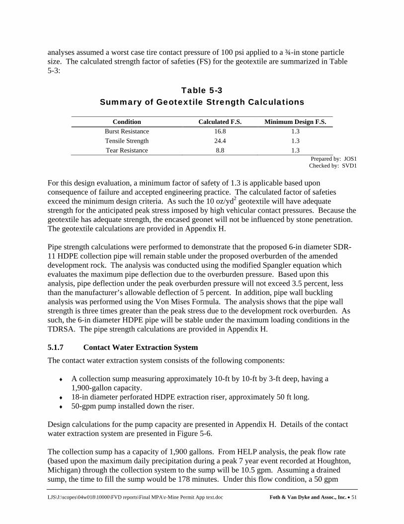
LJS\J:\scopes\04w018\10000\FVD reports\Final MPA\r-Mine Permit App text.doc Foth & Van Dyke and Assoc., Inc. • 51
analyses assumed a worst case tire contact pressure of 100 psi applied to a ¾-in stone particle size. The calculated strength factor of safeties (FS) for the geotextile are summarized in Table 5-3:
Table 5-3 Summary of Geotextile Strength Calculations
Condition Calculated F.S. Minimum Design F.S.
Burst Resistance 16.8 1.3 Tensile Strength 24.4 1.3 Tear Resistance 8.8 1.3
Prepared by: JOS1 Checked by: SVD1
For this design evaluation, a minimum factor of safety of 1.3 is applicable based upon consequence of failure and accepted engineering practice. The calculated factor of safeties exceed the minimum design criteria. As such the 10 oz/yd2 geotextile will have adequate strength for the anticipated peak stress imposed by high vehicular contact pressures. Because the geotextile has adequate strength, the encased geonet will not be influenced by stone penetration. The geotextile calculations are provided in Appendix H. Pipe strength calculations were performed to demonstrate that the proposed 6-in diameter SDR-11 HDPE collection pipe will remain stable under the proposed overburden of the amended development rock. The analysis was conducted using the modified Spangler equation which evaluates the maximum pipe deflection due to the overburden pressure. Based upon this analysis, pipe deflection under the peak overburden pressure will not exceed 3.5 percent, less than the manufacturer’s allowable deflection of 5 percent. In addition, pipe wall buckling analysis was performed using the Von Mises Formula. The analysis shows that the pipe wall strength is three times greater than the peak stress due to the development rock overburden. As such, the 6-in diameter HDPE pipe will be stable under the maximum loading conditions in the TDRSA. The pipe strength calculations are provided in Appendix H. 5.1.7 Contact Water Extraction System
The contact water extraction system consists of the following components:
♦ A collection sump measuring approximately 10-ft by 10-ft by 3-ft deep, having a 1,900-gallon capacity.
♦ 18-in diameter perforated HDPE extraction riser, approximately 50 ft long. ♦ 50-gpm pump installed down the riser.
Design calculations for the pump capacity are presented in Appendix H. Details of the contact water extraction system are presented in Figure 5-6. The collection sump has a capacity of 1,900 gallons. From HELP analysis, the peak flow rate (based upon the maximum daily precipitation during a peak 7 year event recorded at Houghton, Michigan) through the collection system to the sump will be 10.5 gpm. Assuming a drained sump, the time to fill the sump would be 178 minutes. Under this flow condition, a 50 gpm
LJS\J:\scopes\04w018\10000\FVD reports\Final MPA\r-Mine Permit App text.doc Foth & Van Dyke and Assoc., Inc. • 52
pump has been selected for use in the TDRSA primary extraction sump. Because this is a worst case flow condition (i.e., the facility open without the cover geomembrane installed) a smaller pump may be installed when the temporary cover has been placed. The pump sizing calculations are provided in Appendix H. 5.1.7.1 Collection Pipe Clean Out Part of the contact water collection system will be sideslope clean-out risers for periodic cleaning of the 6-in diameter contact water collection line. The clean-out risers will be directly connected to the collection line to allow cleaning by high pressure water jet of the perforated collection line. Clean-out access will be provided at both north and south ends of the TDRSA to facilitate pipe cleaning from two sides of the TDRSA. Upon construction of the TDRSA the 6-in diameter SDR-11 HDPE collection line will be initially jetted to remove any sediments collected in the line during construction. 5.1.8 Leak Detection System A leak detection system (LDS) is included in the design of the TDRSA to provide early warning of potential water leakage through the composite liner system. The LDS is provided at the low point of the TRDSA below the contact water collection sump as shown in Figure 5-6. The rationale for the LDS design is as follows:
♦ The TDRSA is a temporary containment facility to be in service for about seven years. As such there are no concerns over potential long-term leakage from the TDRSA.
♦ The TDRSA composite liner will be subjected to a rigorous quality assurance and quality
control process that includes a leak location survey prior to use. The leak location survey tests the water tightness of the geomembrane after installation. As such the liner is tested under conditions that are expected to exist during operation of the TDRSA.
♦ The contact water collection sump is the low point in the liner system and will have a
head on it the majority of the time. As such this location reflects the worst case conditions for the composite liner as related to potential leakage.
♦ A comprehensive groundwater monitoring program around the TDRSA is proposed in
Section 6. The groundwater monitoring program consists of monitoring wells within 150 ft of the TDRSA that are monitored on a regular basis in accordance with R 425.406.
The LDS for the TDRSA consists of the following components:
♦ An 18-in diameter HDPE extraction riser with a submersible sideslope riser pump.
♦ A collection sump measuring 10-ft by 8-ft by 2-ft deep, having a capacity of approximately 1,200 gallons.
♦ An underlying liner system to prevent release of detection liquid that will consist of a
60-mil HDPE underlain by a GCL.

LJS\J:\scopes\04w018\10000\FVD reports\Final MPA\r-Mine Permit App text.doc Foth & Van Dyke and Assoc., Inc. • 53
Construction QA/QC procedures for the entire TDRSA composite liner system including the subgrade, LDS, and liner will be conducted in accordance with the CQA plan provided in Appendix I. 5.2 TDRSA Operations
The TDRSA will be operated to minimize generation of ARD through a combination of efficient filling sequence, amending the development rock with limestone, and placement of a temporary cover. 5.2.1 Filling Sequence The filling sequence for the TDRSA is illustrated in Figure 5-7. Initially an access ramp will be developed to access the TDRSA bottom. Development rock having a typical 3-in to 4-in particle size will be unloaded at the base of the access ramp and graded two feet thick across the entire floor area. A five to 10-foot layer of development rock will then be placed entirely across the base before filling progresses to the peak build-out elevation. Filling will then proceed from north to south to the design grades as illustrated in Figure 5-7. During the filling sequence the outslope of the active face (outslope of unloaded rock) shall not exceed 1:1 (H:V). Table 5-4 shows the development rock quantities relative to the TDRSA filling sequence. Figure 5-7 illustrates the traffic pattern for entering and leaving the TDRSA. The traffic pattern may be modified based upon operational sequencing of filling and rock removal.
Table 5-4 TDRSA Development Rock Filling
Development
Rock Generation Tonnes (1)
Development Rock Balance
m3 (2)
Development Rock Balance
yd3 (2) Filling
Sequence
Facility Development
Year Comments 144,738 72,400 94,700 1 1 Filling across floor area to 5 to 10 ft. 319,301 159,650 208,800 2 2-3 Filling progressing from north to
south
378,913 189,500 247,900 3 4 Filling complete in year 4, 90% of facility has temporary cover installed
378,913 189,500 247,900 4 4 Temporary cover installation complete
Notes: 1) Development rock quantities from McIntosh Engineers. 2) Cubic meters and cubic yards rounded to the nearest hundred.
Prepared by: JOS1/REM Checked by: SVD1
5.2.2 Temporary Cover As discussed previously, the TDRSA will be a temporary storage facility for mine development rock. Based upon the facility timeline shown in Table 4-4, it is expected that the TDRSA will be at final grade in year 3. Rock removal for mine backfilling will begin in year 4. As such there will only be a short period of time (no more than 1 year) where the facility will be entirely capped with the temporary geomembrane cover. Because of the temporary and short term nature

LJS\J:\scopes\04w018\10000\FVD reports\Final MPA\r-Mine Permit App text.doc Foth & Van Dyke and Assoc., Inc. • 54
of this facility, a cover system has been designed that will not only limit precipitation contact with the development rock but will also provide KEMC with operational flexibility. A temporary cover will be placed over the development rock once final rock elevations have been achieved. It is anticipated that cover installation may occur in two phases, dependent upon fill rates. If fill rates are higher such that the TDRSA is filled to capacity in less than two years, then cover installation could occur in one sequence. The proposed temporary cover system for the TDRSA will consist of the following components from bottom to top.
♦ A geotextile fabric (if needed) will be placed on top of the development rock to prevent loss of the bridging layer into the development rock
♦ A bridging layer (if needed) of smaller sized development rock (typically 3-in to 4-in
particle size) to bridge the larger rock yields.
♦ A 4-in to 6-in grading layer of select site soils or geotextile for geomembrane placement.
♦ A geomembrane consisting of a 30-mil PVC liner.
♦ A ballast system consisting of tethered sand bags will be anchored to the geomembrane. Details of the cover system are provided on Figure 5-3. Cross sections of the TDRSA showing proposed cover elevation are shown in Figures 5-8 and 5-9. Initially a non-woven geotextile may be placed over the development rock to prevent loss of the bridging layer into the development rock mass. A bridging layer will then be placed directly over the geotextile to support the sand grading layer (if needed). On-site soils will be used for the sand grading layer, placed 4-inches to 6-inches thick. Once the grading layer is placed, the geomembrane will be installed. The geomembrane installation will follow the construction quality control procedures specified in the CQA plan contained in Appendix I. Sand bags will be used as weights over the geomembrane. Because the TDRSA is a short term facility, a cover system comprised of permanent layered earth is not needed. As such, a ballast system comprised of tethered sand bags will be used to secure the geomembrane. 5.2.3 Removal Sequence Removal of the development rock from the TDRSA will proceed from the north side of the facility to the south. First the temporary cover will be removed in 4 staged sequences to allow access to the underlying rock. Between each cover removal sequence, the underlying development rock will be excavated and returned to the mine. After all the development rock has been removed from a stage area, the underlying contact water collection system and liner systems will be removed and disposed. During rock removal operations, at least two feet of granular material will be maintained over all active lined areas for liner protection. It is expected that development rock removal will occur in 4 stages over a 1 to 2-year period. As discussed in Section 5.1.5.2 in order to maintain stability of the liner system the maximum the differential height of the rock face will be limited to the height presented in Table 5-1.
LJS\J:\scopes\04w018\10000\FVD reports\Final MPA\r-Mine Permit App text.doc Foth & Van Dyke and Assoc., Inc. • 55
5.3 Quality Assurance and Quality Control for Liner and Cover
Construction
During installation of the various liner components of the TDRSA, quality assurance and quality control activities will be performed to ensure that the liner is constructed in accordance to project specifications and permit requirements. This testing program will include, but not be limited to:
♦ field testing and on-site inspections, ♦ laboratory testing, and ♦ certification report preparation.
Construction quality assurance (CQA) procedures have been developed in accordance with Michigan’s Solid Waste Management Rules and are discussed below. A CQA Plan for the construction of the TDRSA is provided in Appendix I. 5.3.1 Field Testing and Inspections A CQA technician, experienced in construction documentation of the various liner components, will be on-site during construction of the TDRSA to provide construction observation, documentation, and testing as outlined in the CQA Plan. The on-site CQA technician will be under the supervision of a professional engineer registered in the State of Michigan. Continuous on-site inspections will be provided during all major construction activities of the TDRSA including subgrade preparation, liner system installation, and contact collection system installation. 5.3.2 Laboratory Testing Laboratory testing will be performed as outlined in the CQA Plan. A qualified third-party laboratory will be contracted to provide the specified laboratory testing. Laboratory testing will be required for soils and geosynthetics conformance testing. 5.3.3 Certification Report
Following completion of liner installation and prior to placing the TDRSA into service, a certification report will be prepared, documenting that installation of the various liner components and the contact water collection system was performed in accordance with project specifications and manufacturer’s specifications. The report will be certified by a professional engineer registered in the State of Michigan. Details of the certification report are provided in the CQA Plan in Appendix I. 5.4 COSA
As described in Section 4.3.6, the COSA will be constructed to contain mined ore. The COSA building will measure approximately 1,394 m2 (15,000 ft2) having a storage capacity of 3,000 m3 (3,924 yd3). This building will be enclosed on three sides and constructed of steel framing with steel siding. A clear plastic drop door will be installed across the open site to minimize precipitation contact with the ore and reduce fugitive dust release. The floor of the COSA will be constructed of 12 in thick reinforced concrete sloping to a catch basin for collection of contact water. Any collected contact water will be pumped to the CWBs for treatment. Because the ore

LJS\J:\scopes\04w018\10000\FVD reports\Final MPA\r-Mine Permit App text.doc Foth & Van Dyke and Assoc., Inc. • 56
will contain no significant free water, very little contact water generation is expected. The COSA design features will provide adequate containment for the mined ore and will prevent exposure of it to the environment.

LJS\J:\scopes\04w018\10000\FVD reports\Final MPA\r-Mine Permit App text.doc Foth & Van Dyke and Assoc., Inc. • 57
6 Operations Monitoring Plan The operations monitoring plan described in this section is designed to meet the requirements of R 425.203 and R 425.406. The monitoring plan includes the following elements:
♦ Monitoring the TDRSA. ♦ Monitoring the geochemistry of the water pumped from the TDRSA and underground
mine. ♦ Monitoring groundwater quality surrounding the Eagle Project facilities and mine. ♦ Monitoring regional streamflow and quality. ♦ Monitoring regional groundwater elevations. ♦ Monitoring flora and fauna. ♦ Inspection of berms and embankments. ♦ Miscellaneous operational monitoring activities for environmental protection.
Per R 425.203(g) this plan does not include monitoring that will be completed in accordance with the groundwater discharge permit, air permit or storm water construction and industrial storm water permits. Post-closure monitoring is described in the reclamation plan in Section 7. 6.1 Monitoring of the Temporary Development Rock Storage Area
and Mine Water
TDRSA and mine water monitoring will consist of several elements which include:
♦ Monitoring the leak detection system beneath the TDRSA. ♦ Monitoring the head levels on the TDRSA liner. ♦ Monitoring the chemistry of the water pumped from the underground mine and TDRSA
to the CWBs. 6.1.1 Leak Detection System The leak detection system is monitored using a liquid level sensor that provides a measurement of the liquid level (if any) in the leak detection sump. If liquid is present, a pump is manually operated and a sample is drawn directly from the sump into the appropriate sample containers. Water that collects in this secondary liner system, if any, will be pumped out, recorded and analyzed for key parameters indicative of TDRSA water passing through the TDRSA composite liner. Table 6-1 summarizes the parameter list for the water samples collected from the leak detection system. Note that it is expected that there will be some water in the collection sump after the TDRSA is constructed. This is due to precipitation falling in the sump during construction. As such, the chemistry of the water from the leak detection system sump will be analyzed for key parameters at concentrations indicative of the characteristics of the contact water.

LJS\J:\scopes\04w018\10000\FVD reports\Final MPA\r-Mine Permit App text.doc Foth & Van Dyke and Assoc., Inc. • 58
Table 6-1 Leak Detection System Sump Water Quality Parameters List
Parameter Analytical Method Reporting Limit Units
Sulfate EPA-375.4/9038 1.0(1) mg/l pH Field Measurement -- standard pH units
(1)Sulfate levels of approximately 500 mg/l will be indicative of leakage from the TDRSA composite liner. Prepared by: SVD1
Checked by: JSK
6.1.2 TDRSA Contact Water Collection System Monitoring of the TDRSA contact water collection system is designed to verify, per R 425.409, that the level of contact water in the collection system never exceeds one foot of head on the facility composite liner system, (excluding the sump), except as needed for the CWB contingency plan (see Section 8). Head levels in the TDRSA will be monitored continuously through use of a pressure transducer. The pressure transducer will be installed with the sump pump in the extraction sump (see Figure 5-6). The pressure transducer and extraction sump will be instrumented and controlled to pump water out of the sump at levels that maintain less than one foot of head on the TDRSA liner. The water levels will be reviewed during operations on a weekly basis to confirm system performance. As described in the contingency plan, the TDRSA may be used, on an emergency basis, for the temporary storage of contact water during rare extreme snow melt conditions when the water flow to the WWTP and CWBs may exceed WWTP and CWB capacity. The 6-in diameter contact water collection line will be cleaned annually no later than October of each year. Cleaning will be conducted by a certified high pressure line cleaner contracted by KEMC. 6.1.3 TDRSA and Mine Water Monitoring
The geochemistry of the water pumped from the TDRSA and mine has been estimated from the geochemistry testing program documented by Geochimica, Inc. and summarized in technical memoranda provided in Appendix D-3 and Appendix D-4. As part of the ongoing geochemistry assessment of the mine operations, KEMC will analyze water samples from the TDRSA and mine on a quarterly basis and annual in accordance with the parameter list specified in Table 6-2.
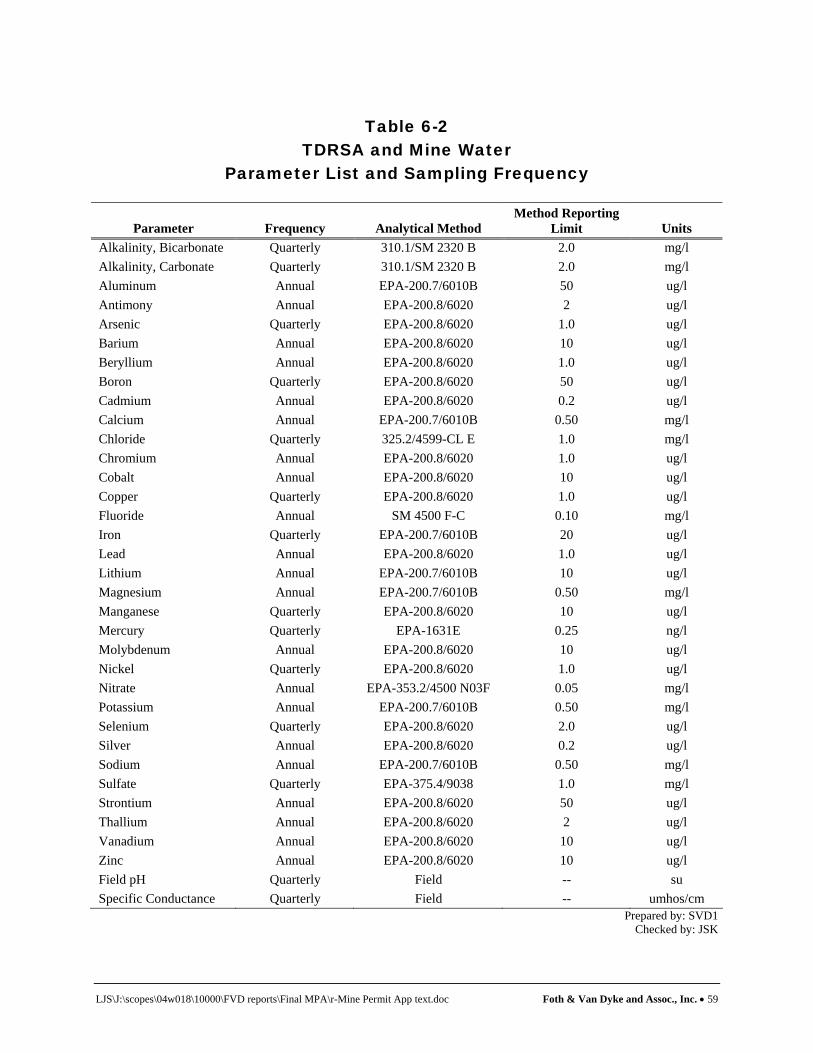
LJS\J:\scopes\04w018\10000\FVD reports\Final MPA\r-Mine Permit App text.doc Foth & Van Dyke and Assoc., Inc. • 59
Table 6-2
TDRSA and Mine Water Parameter List and Sampling Frequency
Parameter Frequency Analytical Method Method Reporting
Limit Units Alkalinity, Bicarbonate Quarterly 310.1/SM 2320 B 2.0 mg/l Alkalinity, Carbonate Quarterly 310.1/SM 2320 B 2.0 mg/l Aluminum Annual EPA-200.7/6010B 50 ug/l Antimony Annual EPA-200.8/6020 2 ug/l Arsenic Quarterly EPA-200.8/6020 1.0 ug/l Barium Annual EPA-200.8/6020 10 ug/l Beryllium Annual EPA-200.8/6020 1.0 ug/l Boron Quarterly EPA-200.8/6020 50 ug/l Cadmium Annual EPA-200.8/6020 0.2 ug/l Calcium Annual EPA-200.7/6010B 0.50 mg/l Chloride Quarterly 325.2/4599-CL E 1.0 mg/l Chromium Annual EPA-200.8/6020 1.0 ug/l Cobalt Annual EPA-200.8/6020 10 ug/l Copper Quarterly EPA-200.8/6020 1.0 ug/l Fluoride Annual SM 4500 F-C 0.10 mg/l Iron Quarterly EPA-200.7/6010B 20 ug/l Lead Annual EPA-200.8/6020 1.0 ug/l Lithium Annual EPA-200.7/6010B 10 ug/l Magnesium Annual EPA-200.7/6010B 0.50 mg/l Manganese Quarterly EPA-200.8/6020 10 ug/l Mercury Quarterly EPA-1631E 0.25 ng/l Molybdenum Annual EPA-200.8/6020 10 ug/l Nickel Quarterly EPA-200.8/6020 1.0 ug/l Nitrate Annual EPA-353.2/4500 N03F 0.05 mg/l Potassium Annual EPA-200.7/6010B 0.50 mg/l Selenium Quarterly EPA-200.8/6020 2.0 ug/l Silver Annual EPA-200.8/6020 0.2 ug/l Sodium Annual EPA-200.7/6010B 0.50 mg/l Sulfate Quarterly EPA-375.4/9038 1.0 mg/l Strontium Annual EPA-200.8/6020 50 ug/l Thallium Annual EPA-200.8/6020 2 ug/l Vanadium Annual EPA-200.8/6020 10 ug/l Zinc Annual EPA-200.8/6020 10 ug/l Field pH Quarterly Field -- su Specific Conductance Quarterly Field -- umhos/cm
Prepared by: SVD1 Checked by: JSK
LJS\J:\scopes\04w018\10000\FVD reports\Final MPA\r-Mine Permit App text.doc Foth & Van Dyke and Assoc., Inc. • 60
6.2 Groundwater Quality Monitoring
Groundwater quality monitoring around various Eagle Project facilities will be completed on a quarterly and annual basis. Monitoring of groundwater surrounding the TWIS is described in the Groundwater Discharge Permit Application (Foth & Van Dyke, 2006). As part of the Eagle Project operations, groundwater quality will also be monitored around the TDRSA, CWBs and the underground mine. A description of the background monitoring wells and the number and location of wells for each facility is provided in Sections 6.2.1 through 6.2.5(1). Groundwater elevation will also be measured each time a sample is obtained. 6.2.1 Background Monitoring Wells Figure 6-1 displays the facility plan with existing, and proposed monitoring wells located to assess facility performance. Figure 6-1 also displays wells that will be abandoned in accordance with MDEQ requirements due to facility construction activities. Wells QAL026 A/D/E are located upgradient of the main site facility and are the designated background monitoring wells for project facilities and the underground mine. The background monitoring wells will monitor background groundwater quality in the A Zone and D Zone hydrostratigraphic units comprised of outwash sands, and the E Zone hydrostratigraphic unit comprised of glacial till. 6.2.2 TDRSA Monitoring Wells Figure 6-1 displays the location of wells for monitoring groundwater quality along the downgradient side (east) of the TDRSA. As required by R 425.406, a well is located at the limits of the TDRSA. Additional compliance monitoring wells are located 150 ft downgradient of the TDRSA. 6.2.3 Contact Water Basin Monitoring Wells Figure 6-1 displays the location of wells for groundwater quality monitoring along the downgradient side (east) of the CWBs. 6.2.4 Underground Mine Figure 6-1 displays the location of wells for monitoring groundwater quality surrounding the underground mine. As displayed on Figure 6-1 the wells are located within and surrounding the vertical projection of the limits of the mineable resource and the mine workings. As required by R 425.406 compliance monitoring wells are located 150 ft from the limits of the mine. 6.2.5 Groundwater Monitoring Parameters List
Table 6-3 summarizes the parameter list and sampling frequency for the groundwater monitoring program. Analytical methods and reporting limits are also provided in Table 6-3. (1)See note 7 on Figure 6-1 for designated purpose of wells for groundwater quality monitoring program.
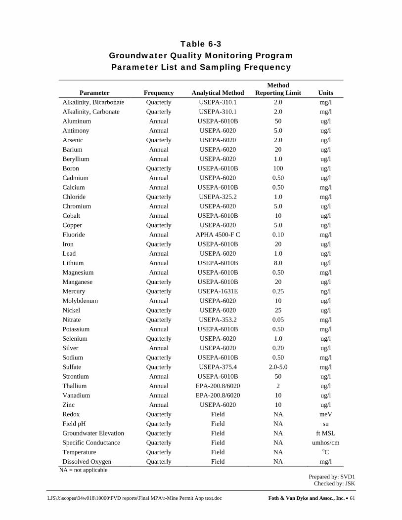
LJS\J:\scopes\04w018\10000\FVD reports\Final MPA\r-Mine Permit App text.doc Foth & Van Dyke and Assoc., Inc. • 61
Table 6-3 Groundwater Quality Monitoring Program Parameter List and Sampling Frequency
Parameter Frequency Analytical Method Method
Reporting Limit Units Alkalinity, Bicarbonate Quarterly USEPA-310.1 2.0 mg/l Alkalinity, Carbonate Quarterly USEPA-310.1 2.0 mg/l Aluminum Annual USEPA-6010B 50 ug/l Antimony Annual USEPA-6020 5.0 ug/l Arsenic Quarterly USEPA-6020 2.0 ug/l Barium Annual USEPA-6020 20 ug/l Beryllium Annual USEPA-6020 1.0 ug/l Boron Quarterly USEPA-6010B 100 ug/l Cadmium Annual USEPA-6020 0.50 ug/l Calcium Annual USEPA-6010B 0.50 mg/l Chloride Quarterly USEPA-325.2 1.0 mg/l Chromium Annual USEPA-6020 5.0 ug/l Cobalt Annual USEPA-6010B 10 ug/l Copper Quarterly USEPA-6020 5.0 ug/l Fluoride Annual APHA 4500-F C 0.10 mg/l Iron Quarterly USEPA-6010B 20 ug/l Lead Annual USEPA-6020 1.0 ug/l Lithium Annual USEPA-6010B 8.0 ug/l Magnesium Annual USEPA-6010B 0.50 mg/l Manganese Quarterly USEPA-6010B 20 ug/l Mercury Quarterly USEPA-1631E 0.25 ng/l Molybdenum Annual USEPA-6020 10 ug/l Nickel Quarterly USEPA-6020 25 ug/l Nitrate Quarterly USEPA-353.2 0.05 mg/l Potassium Annual USEPA-6010B 0.50 mg/l Selenium Quarterly USEPA-6020 1.0 ug/l Silver Annual USEPA-6020 0.20 ug/l Sodium Quarterly USEPA-6010B 0.50 mg/l Sulfate Quarterly USEPA-375.4 2.0-5.0 mg/l Strontium Annual USEPA-6010B 50 ug/l Thallium Annual EPA-200.8/6020 2 ug/l Vanadium Annual EPA-200.8/6020 10 ug/l Zinc Annual USEPA-6020 10 ug/l Redox Quarterly Field NA meV Field pH Quarterly Field NA su Groundwater Elevation Quarterly Field NA ft MSL Specific Conductance Quarterly Field NA umhos/cm Temperature Quarterly Field NA oC Dissolved Oxygen Quarterly Field NA mg/l
NA = not applicable Prepared by: SVD1
Checked by: JSK

LJS\J:\scopes\04w018\10000\FVD reports\Final MPA\r-Mine Permit App text.doc Foth & Van Dyke and Assoc., Inc. • 62
6.3 Regional Hydrologic Monitoring
As part of the operations environmental monitoring plan, KEMC will implement regional hydrologic monitoring program to evaluate local and regional streamflow and quality and local and regional groundwater elevations. Sections 6.3.1 and 6.3.2 describe the hydrologic monitoring that KEMC will implement per the requirements of R 425.203(g) and R 425.406. 6.3.1 Surface Water Monitoring Figure 6-2 displays the location of surface water monitoring stations that were employed for the baseline hydrologic studies that will be used for monitoring potential environmental impacts to streamflow and surface water quality. Four monitoring stations are included on the Salmon Trout River Main Branch. Two monitoring stations are located on the Salmon Trout River East Branch. One monitoring station is located on the Yellow Dog River. One monitoring station is located on the Cedar River and will be monitored to collect data in a reference watershed that will not be influenced by project activities. Surface Water Flow Surface water monitoring stations STRM004, STRM005, STRE002 and YDRM002 have been instrumented with continuous monitoring devices for temperature, conductivity and stage. KEMC will continue to operate these monitoring stations and devices during the mining project. Continuous measurements of stream stage will be used to derive flow data from rating curves of the stage/discharge relationship as presented in the Baseline Hydrology Study (North Jackson Company, 2005). In addition, monitoring stations STRM001, STRM002, STRE001 and CDRM004 will be monitored for streamflow on a quarterly basis coinciding with surface water quality measurements. Surface Water Quality The quarterly surface water monitoring events will take place during the summer baseflow (August), fall rain (likely October of each year), winter baseflow (February) and spring snowmelt and runoff (likely April of each year). Figure 6-2 shows the location of existing surface water quality monitoring stations that were used for the baseline studies. Monitoring stations STRM001, STRM002, STRM004, STRM005, STRE001, STRE002, YDRM002 and CDRM004 will be monitored on a quarterly basis for the parameters listed in Table 6-4.

LJS\J:\scopes\04w018\10000\FVD reports\Final MPA\r-Mine Permit App text.doc Foth & Van Dyke and Assoc., Inc. • 63
Table 6-4 Surface Water Quality Monitoring Program Parameter List and Sampling Frequency
Parameter Frequency Analytical
Method Method
Reporting Limit Units Field Temperature Quarterly Field NA oC D.O. Quarterly Field NA mg/l Specific Conductance Quarterly Field NA umhos/cm pH Quarterly Field NA su Metals Aluminum Annual EPA-200.7/6010B 50 ug/l Lithium Annual EPA-200.7/6010B 10 ug/l Antimony Annual EPA-200.8/6020 2.0 ug/l Arsenic Quarterly EPA-200.8/6020 1.0 ug/l Barium Annual EPA-200.8/6020 10 ug/l Iron Quarterly EPA-200.7/6010B 20 ug/l Beryllium Annual EPA-200.8/6020 1.0 ug/l Boron Quarterly EPA-200.8/6020 50 ug/l Cadmium Annual EPA-200.8/6020 0.2 ug/l Chromium Annual EPA-200.8/6020 1.0 ug/l Copper Quarterly EPA-200.8/6020 1.0 ug/l Cobalt Quarterly EPA-200.8/6020 10 ug/l Lead Annual EPA-200.8/6020 1.0 ug/l Manganese Quarterly EPA-200.8/6020 10 ug/l Molybdenum Annual EPA-200.8/6020 10 ug/l Nickel Quarterly EPA-200.8/6020 1.0 ug/l Selenium Quarterly EPA-200.8/6020 2.0 ug/l Silver Annual EPA-200.8/6020 0.2 ug/l Zinc Annual EPA-200.8/6020 10 ug/l Mercury Quarterly EPA-1631E 0.25 ng/l Anions Alkalinity, Bicarbonate Annual 310.1/SM 2320 B 2.0 mg/l Alkalinity, Carbonate Annual 310.1/SM 2320 B 2.0 mg/l Chloride Annual 325.2/4500-CL E 1.0 mg/l Fluoride Annual SM 4500 F-C 0.10 mg/l Nitrate-N Annual 353.2/4500 NO3F 0.05 mg/l Sulfate Quarterly EPA-375.4/9038 1.0 mg/l Cations Calcium Annual EPA-200.7/6010B 0.50 mg/l Potassium Annual EPA-200.7/6010B 0.50 mg/l Magnesium Annual EPA-200.7/6010B 0.50 mg/l Sodium Annual EPA-200.7/6010B 0.50 mg/l Total Dissolved Solids Quarterly EPA-160.1 50 mg/l
Prepared by: SVD1 Checked by: JS

LJS\J:\scopes\04w018\10000\FVD reports\Final MPA\r-Mine Permit App text.doc Foth & Van Dyke and Assoc., Inc. • 64
6.3.2 Regional Groundwater Elevation Monitoring Figure 6-3 displays the wells that, in addition to those displayed on Figure 6-1, will be employed to monitor potential groundwater elevation changes due to mine dewatering. The regional monitoring wells cover an area of approximately 14 square miles. Groundwater elevation will be monitored on a quarterly basis coinciding with the quarterly monitoring events described in Section 6.2. The wells for the regional groundwater elevation monitoring program were selected based on the following criteria:
♦ Regional coverage to assess potential changes in the groundwater divide between groundwater basins of the Salmon Trout River Main Branch, Salmon Trout River East Branch, and the Yellow Dog River.
♦ Proximity to surface water systems and wetlands.
♦ Formation in which the well is screened.
Collectively, the monitoring of groundwater elevation in the wells shown on Figure 6-3 and those included in the groundwater quality monitoring program (Figure 6-1) will allow KEMC to assess changes in the groundwater elevations and flow due to mine dewatering. 6.4 Groundwater and Surface Water Sampling Procedures
The collection of groundwater samples, water samples from the TDRSA and mine, and surface water samples will be completed in accordance with the Eagle Project Quality Assurance Project Plan and Standard Operating Procedures (North Jackson, 2004a and 2004b). These quality control documents have been previously provided to MDEQ and describe the following per R 425.203:
♦ Surface water sampling procedures ♦ Groundwater sampling procedures including well purging procedures. ♦ Procedures to prevent cross contamination of samples. ♦ QA/QC program including the use of field blanks and duplicates. ♦ Procedures for the collection of groundwater and surface water field data. ♦ Sample preservation, documentation and chain-of-custody procedures. ♦ Data validation procedures. ♦ Well installation development and abandonment procedures.
During operations groundwater and surface water quality data will be statistically assessed for distributional changes as a result of site activities. Statistical methods will include testing for trends in water chemistry, and comparing constituent concentration levels to those observed in background or upgradient locations. Appropriate parametric or nonparametric statistical methods will be selected in consideration of the observed data characteristics, namely, the distributional form of the data and the degree of left censuring (amount of data below detection). In addition, sources of variation in the data unrelated to site activities, such as seasonality, will be statistically estimated and controlled. Relevant documents containing guidance for selecting appropriate statistical tests are:

LJS\J:\scopes\04w018\10000\FVD reports\Final MPA\r-Mine Permit App text.doc Foth & Van Dyke and Assoc., Inc. • 65
♦ MDEQ, 2002. Sampling Strategies and Statistics Training Materials for Part 201
Cleanup Criteria. ♦ Gilbert, R.O., 1987. Statistical Methods for Environmental Pollution Monitoring, Van
Nostrand Reinhold, New York.
♦ USEPA, 2000. Practical Methods for Data Analysis–EPA QA/G-9, EPA/600/R-96/084.
♦ USEPA, 1992. Statistical Analysis for Groundwater Monitoring Data at RCRA Facilities – Addendum to Interim Final Guidance, PB89-151047.
KEMC will provide to MDEQ quarterly and annual summary reports of monitoring data and analyses completed. All related mine monitoring data will be maintained by KEMC in a database including well borehole logs and construction forms. 6.5 Berms Embankments and Basins
The exterior containment berms and embankments of the TDRSA, CWBs and the NCWIBs will be inspected monthly or after any rainfall event that exceeds ½ inch in a 24-hour period. These inspections will identify preventative maintenance required to maintain stability of the berms and embankments. A surface inspection log will be maintained at the Eagle Project site that documents the results of these inspections. The preventative maintenance, inspection and corrective maintenance procedures are as follows:
♦ Inspect ditches and storm water conveyance structures. Record the location of any erosion or siltation and clean any sediment from ditches and culvert pipes sediment cleaned from ditches and culvert pipes will be disposed of in the TDRSA.
♦ Inspect berms for cracking or settlement. Record location and extent of same. Provide
required materials to repair impacted area. The CWBs will be checked via staff gage or probe monthly to determine the thickness of the sediment accumulated in the bottom of each of the two basins. When the sediment thickness exceeds the maximum design thickness of three feet the CWB will be cleaned out. Removed sediment will be disposed of in the TDRSA. The four NCWIBs are labeled as NCWIB #3, NCWIB #4, NCWIB #5 and NCWIB #6 and receive storm water runoff from the areas of the mine site and the mine backfill surface facilities that do not come in contact with ore or development rock. These facilities will be monitored in accordance with the storm water permits for the project. 6.6 Biological Monitoring
Figure 6-4 shows the locations of monitoring stations and transects that were established as part of the baseline studies for threatened and endangered species and wildlife. Also displayed are mapped wetlands and the location of identified populations of the state-listed threatened plant species the narrow-leaved gentian as determined by Wetland and Coastal Resources, Inc. (WCR)

LJS\J:\scopes\04w018\10000\FVD reports\Final MPA\r-Mine Permit App text.doc Foth & Van Dyke and Assoc., Inc. • 66
(2005a). During operations, KEMC is proposing to implement a biological monitoring program to document the condition of local biological resources. 6.6.1 Threatened and Endangered Species Monitoring As documented in the EIA in Volume II of this application, the narrow-leaved gentian has been mapped in nearby locations in wetland fringe and upland areas and is not expected to be impacted by mine dewatering operations. As such no mitigation plans are required for this species. KEMC is proposing to document on an annual basis the health of the narrow-leaved gentian communities identified along the Salmon Trout River Main Branch south of the Triple A Road. The annual evaluation will include an assessment of local climatic conditions (drought, insect infestations, precipitation, etc.), photographic documentation and a visual description of the health of the colonies relative to other colonies that have been documented in the area as described in the EIA. The locations of narrow-leaved gentian communities at the Eagle Project site are shown in Figure 6-4. The narrow-leaved gentian was the only state-listed species at the project site. The monitoring of the narrow-leaved gentian will not be used for compliance assessment purposes. 6.6.2 Wetland Monitoring Wetlands in the Eagle Project area were identified and described by WCR. WCR, (2005b, 2006) identified the approximate size and location of wetlands which are shown on Figure 6-4. Figure 6-4 shows the location of selected wetlands adjacent to the ore body and mine site that will be monitored during mine operations and include the following:
♦ Ore body and backfill facility – wetland areas 1, 6, 7, 8, 9, 10, 11, 12 and 13. ♦ Mine surface facility – wetland area 26
The monitoring and observation of the wetlands listed above will include the following:
♦ Monitoring of shallow groundwater levels in nested wetland piezometers shown in Figure 6-5.
♦ An annual visual assessment of these wetlands for wetland vegetation.
The wetland data collected will be submitted with the annual monitoring report required under R 425.501. The monitoring of wetland conditions will be completed to confirm EIA predictions on wetland impacts and will not be used for compliance assessment purposes. 6.6.3 Flora/Fauna Monitoring
WCR completed a field assessment of small mammals, birds, frogs and toads, along with their preferred habitats, during spring, summer and fall of 2004. The results of the assessment have been reported by WCR (2005c) and include habitat and wildlife typical of the Upper Peninsula of Michigan.

LJS\J:\scopes\04w018\10000\FVD reports\Final MPA\r-Mine Permit App text.doc Foth & Van Dyke and Assoc., Inc. • 67
During the initial assessment, seven wildlife sampling transects were established and surveyed. These transects and transect numbers are shown on Figure 6-4. The transects include 21 wildlife sampling stations and three frog/toad sampling stations located within the various habitat types. Flora and fauna monitoring during Eagle Project operations will include the following:
♦ Semi-annual (spring and fall) observations along the seven transects. ♦ Recording observations at the 21 wildlife sampling stations. ♦ Recording observations at the three frog/toad sampling stations.
Observations will be documented and included with the Eagle Project’s annual report required under R 425.501. The flora and fauna monitoring will be completed to confirm baseline conditions and document the trends and conditions of these resources during operations. The flora and fauna monitoring will not be used for compliance assessment purposes. 6.6.4 Aquatics Figure 6-6 shows the location of aquatic monitoring stations that were established as part of the baseline study (WCR, 2005d). During operations KEMC will continue to monitor and assess the fisheries and aquatic macro invertebrate populations at these locations. Annual assessments will take place in late summer to early fall. The annual surveys will be documented and included in the Eagle Project’s annual report required under R 425.501. The aquatic monitoring will be completed to confirm baseline conditions and document trends and conditions of these resources during operations. The aquatic monitoring will not be used for compliance assessment purposes. 6.7 Miscellaneous Monitoring Activities
During operations other miscellaneous environmentally related monitoring activities will be implemented by KEMC. These activities are summarized in the following Table 6-5. 6.8 Minimization and Mitigation of Impacts
R 425.203(k) requires that an applicant for a mining permit prepare and submit plans to prevent, minimize and mitigate adverse impacts of the proposed mining operation on flora, fish, wildlife habitat and biodiversity. KEMC’s mine planning team, described in Section 1 of this document, has thoroughly studied the environment in the vicinity of the proposed Eagle Project site. In so doing, the mining plans that have been developed and described in Sections 4, 5, 7 and 8 were designed to prevent and minimize adverse impacts on the surrounding environment. Mine facilities have been located away from wetland and surface water resources. Mine facility construction will not disturb any known listed species. Facilities are located in areas that have previously been disturbed by logging and thus unique habitats and biodiversity will not be affected. While a listed plant species, the narrow-leaved gentian, was found within riparian wetlands along the Salmon Trout River Main Branch, documented abundant populations in a variety of habitats (see EIA in Volume II of this application) indicate potential secondary impacts on the local populations will not affect the viability of the local identified communities. As such KEMC is not proposing any additional mitigation measures outside of those that are incorporated into the mining plan.
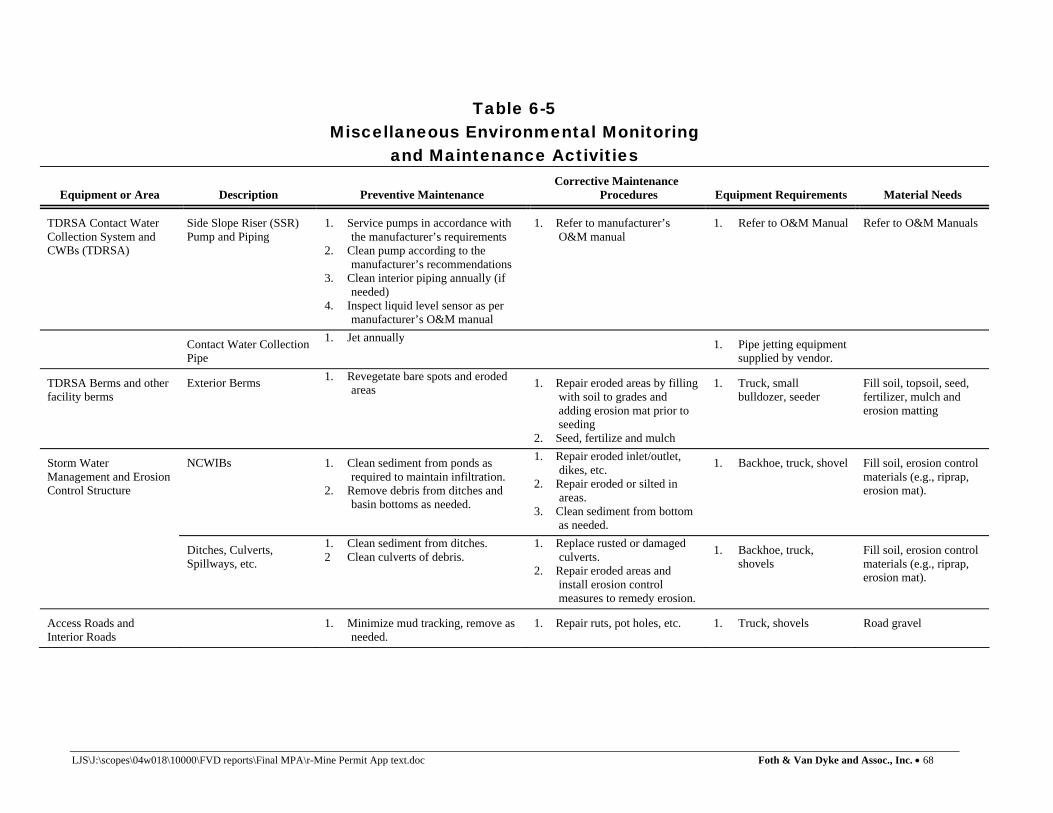
LJS\J:\scopes\04w018\10000\FVD reports\Final MPA\r-Mine Permit App text.doc Foth & Van Dyke and Assoc., Inc. • 68
Table 6-5 Miscellaneous Environmental Monitoring
and Maintenance Activities
Equipment or Area Description Preventive Maintenance Corrective Maintenance
Procedures Equipment Requirements Material Needs
TDRSA Contact Water Collection System and CWBs (TDRSA)
Side Slope Riser (SSR) Pump and Piping
1. Service pumps in accordance with the manufacturer’s requirements
2. Clean pump according to the manufacturer’s recommendations
3. Clean interior piping annually (if needed)
4. Inspect liquid level sensor as per manufacturer’s O&M manual
1. Refer to manufacturer’s O&M manual
1. Refer to O&M Manual
Refer to O&M Manuals
Contact Water Collection Pipe
1. Jet annually 1. Pipe jetting equipment supplied by vendor.
TDRSA Berms and other facility berms
Exterior Berms 1. Revegetate bare spots and eroded areas 1. Repair eroded areas by filling
with soil to grades and adding erosion mat prior to seeding
2. Seed, fertilize and mulch
1. Truck, small bulldozer, seeder
Fill soil, topsoil, seed, fertilizer, mulch and erosion matting
Storm Water Management and Erosion Control Structure
NCWIBs 1. Clean sediment from ponds as required to maintain infiltration.
2. Remove debris from ditches and basin bottoms as needed.
1. Repair eroded inlet/outlet, dikes, etc.
2. Repair eroded or silted in areas.
3. Clean sediment from bottom as needed.
1. Backhoe, truck, shovel Fill soil, erosion control materials (e.g., riprap, erosion mat).
Ditches, Culverts, Spillways, etc.
1. Clean sediment from ditches. 2 Clean culverts of debris.
1. Replace rusted or damaged culverts.
2. Repair eroded areas and install erosion control measures to remedy erosion.
1. Backhoe, truck, shovels
Fill soil, erosion control materials (e.g., riprap, erosion mat).
Access Roads and Interior Roads
1. Minimize mud tracking, remove as needed.
1. Repair ruts, pot holes, etc. 1. Truck, shovels Road gravel

Table 6-5 (con’t)
LJS\J:\scopes\04w018\10000\FVD reports\Final MPA\r-Mine Permit App text.doc Foth & Van Dyke and Assoc., Inc. • 69
Equipment or Area Description Preventive Maintenance Corrective Maintenance
Procedures Equipment Requirements Material Needs
Soil Stockpiles Topsoil and other soil stockpiles
1. Maintain silt fences. 2. Maintain other erosion control
devices.
1. Replace or repair silt fence as needed.
2. Repair eroded areas including regrading and revegetation.
3. Clean ditches where silt and/or sand has accumulated.
1. Shovel, backhoe Silt fencing
Environmental Monitoring Devices
Groundwater Monitoring Wells
1. Mark wells with flag to prevent damage during other maintenance.
2. Install protector pipes
1. Repair/replace broken protector pipes, surface seals and locks
1. Shovel Protector pipes, concrete lock/key set, PVC pipe
Security Devices Means to Control Entry (fencing/gates) Exterior Lighting
1. Repaint rusted or scratched areas. 2. Replace burnt out bulbs.
1. Repair or replace worn or rusty fences.
2. Repair rusty or out of order locks, etc.
Fence/gate parts and locks
Prepared by: REM Checked by: SVD1

LJS\J:\scopes\04w018\10000\FVD reports\Final MPA\r-Mine Permit App text.doc Foth & Van Dyke and Assoc., Inc. • 70
7 Reclamation Plan This section presents the Eagle Project Reclamation Plan pursuant to R 425.204 and R 425.407. The goal of the reclamation plan is to establish a self sustaining ecosystem that is consistent with local end use goals. A self sustaining ecosystem will simulate the natural biodiversity of the flora and fauna through the reclaimed areas. Reclamation of the property will consist of restoring approximately 90 acres of surface area and the underground mine workings. The proposed reclamation plan will restore the property to a condition commensurate with pre-mining landscape using native vegetation to promote enhancement of wildlife habitat. The final land use of the site will be compatible with existing uses on adjacent properties. Included with the Reclamation Plan are procedures and time lines for closure of both surface and underground facilities and estimated costs. Post-closure monitoring is discussed in Section 7.5. Reclamation of the railhead facility will be assessed upon-site selection and preliminary design. Because the railhead facility will be entirely enclosed, little if any reclamation would be required. Site structures would remain standing and sold to other potential railhead users. At the end of mining operations, KEMC may consider donating one or more Eagle Project structures to the local community for civic use. MDNR and MDEQ will be notified regarding changes in building ownership and uses. 7.1 Reclamation Sequencing and Timing
Reclamation activities related to the proposed development will commence during initial construction activities at the site and will continue through facility closure into the post-closure care period. Reclamation sequencing has been established based upon three different site development events as presented in Table 7-1.
Table 7-1 Reclamation Sequence
Sequence Event Facility
Development Year 1 Site Construction 1-2 2 Closure(1) 8(1), 9-11 3 Post-Closure 12-37(2)
(1)TDRSA closure. (2) Wastewater treatment system will close the 5th year of post-closure, year 17.
Prepared by: JOS1 Checked by: SVD1
Sequence 1 will occur concurrent with site construction, and will include reclaiming areas disturbed during site construction as soon as practical after construction is completed for a particular area. At facility closure after mining activities cease, (Sequence 2) unnecessary site infrastructure will be decommissioned and the property restored to pre-mining conditions. Post-closure reclamation (Sequence 3) will occur after closure for a period of 20 years. Table 7-2 lists significant activities associated with each reclamation sequence.
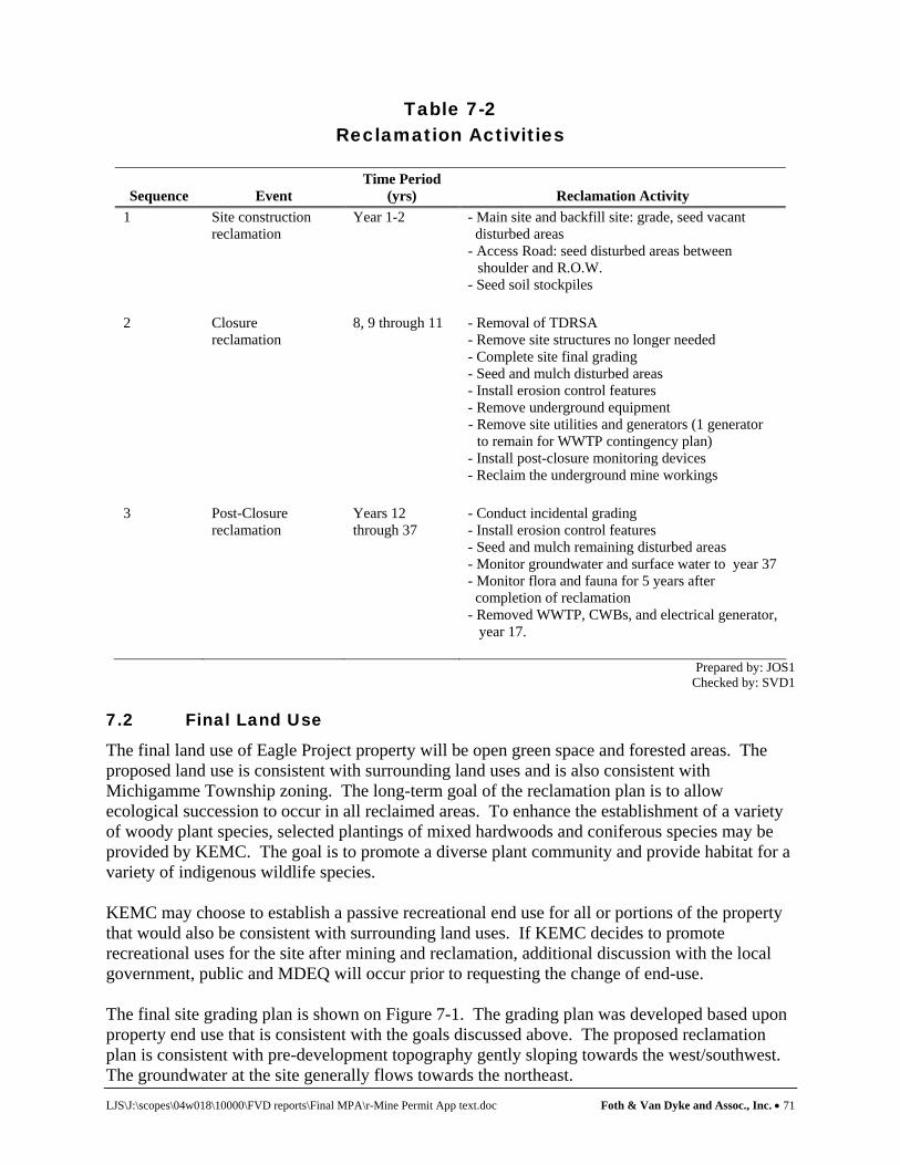
LJS\J:\scopes\04w018\10000\FVD reports\Final MPA\r-Mine Permit App text.doc Foth & Van Dyke and Assoc., Inc. • 71
Table 7-2 Reclamation Activities
Sequence Event Time Period
(yrs) Reclamation Activity 1 Site construction
reclamation Year 1-2 - Main site and backfill site: grade, seed vacant
disturbed areas - Access Road: seed disturbed areas between shoulder and R.O.W. - Seed soil stockpiles
2 Closure reclamation
8, 9 through 11 - Removal of TDRSA - Remove site structures no longer needed - Complete site final grading - Seed and mulch disturbed areas - Install erosion control features - Remove underground equipment - Remove site utilities and generators (1 generator
to remain for WWTP contingency plan) - Install post-closure monitoring devices - Reclaim the underground mine workings
3 Post-Closure reclamation
Years 12 through 37
- Conduct incidental grading - Install erosion control features - Seed and mulch remaining disturbed areas - Monitor groundwater and surface water to year 37 - Monitor flora and fauna for 5 years after completion of reclamation - Removed WWTP, CWBs, and electrical generator, year 17.
Prepared by: JOS1 Checked by: SVD1
7.2 Final Land Use
The final land use of Eagle Project property will be open green space and forested areas. The proposed land use is consistent with surrounding land uses and is also consistent with Michigamme Township zoning. The long-term goal of the reclamation plan is to allow ecological succession to occur in all reclaimed areas. To enhance the establishment of a variety of woody plant species, selected plantings of mixed hardwoods and coniferous species may be provided by KEMC. The goal is to promote a diverse plant community and provide habitat for a variety of indigenous wildlife species. KEMC may choose to establish a passive recreational end use for all or portions of the property that would also be consistent with surrounding land uses. If KEMC decides to promote recreational uses for the site after mining and reclamation, additional discussion with the local government, public and MDEQ will occur prior to requesting the change of end-use. The final site grading plan is shown on Figure 7-1. The grading plan was developed based upon property end use that is consistent with the goals discussed above. The proposed reclamation plan is consistent with pre-development topography gently sloping towards the west/southwest. The groundwater at the site generally flows towards the northeast.

LJS\J:\scopes\04w018\10000\FVD reports\Final MPA\r-Mine Permit App text.doc Foth & Van Dyke and Assoc., Inc. • 72
7.3 Site Construction Reclamation
During site construction reclamation will be performed concurrently for disturbed areas surrounding the facilities under construction. Reclamation of these areas will include proper grading and applying seeding and mulching. Storm water management facilities including grading, ditches and detention basins will be constructed at the start of construction. Silt fences and other erosion control devices will be installed as necessary. 7.4 Closure Reclamation
7.4.1 Surface Facilities Closure for the surface facilities will occur at different times during the life of the facility beginning with the closure of the TDRSA in operating year 8. Closure of the remaining surface facilities and underground facilities is expected to be completed in year 11. However, the CWBs, WWTP and one generator will remain in operation for the first 5 years of post-closure as a contingency for treatment of mine water. It is expected these facilities will close in year 17. 7.4.1.1 TDRSA Closure of the TDRSA is expected to begin in operating year 8. As presented in Section 4 development rock will be returned to the mine as part of the underground reclamation. Upon removal of the development rock, the underlying water collection system and liner will be removed. The water collection drainage layer may be used as backfill in the mine or disposed off-site in accordance with applicable regulations. Geosynthetic liner components including the geomembrane liners, geotextiles and GCL will be removed and disposed of underground or at an approved off-site landfill. Mechanical components such as pumps or other salvageable materials will be removed from the property. Upon removal of all facility components, the area will be regraded to allow efficient use of the area during continued mining operation. Table 7-3 provides a breakdown of materials and quantities required for reclamation of the TDRSA.
Table 7-3 TDRSA Reclamation
Component Quantity Disposal Collection Sand ~9,700 yd3 Mine Backfill1
Collection Piping ~660 lin ft Salvage
Collection Pump(s) 2 ea Landfill1
Geomembrane Liner ~262,000 ft2 Landfill1
Geotextile/GCL ~262,000 ft2 Landfill1
Cover Geomembrane ~263,000 ft2 Landfill1
1Or other approved method. Prepared by: JOS1
Checked by: SVD1

LJS\J:\scopes\04w018\10000\FVD reports\Final MPA\r-Mine Permit App text.doc Foth & Van Dyke and Assoc., Inc. • 73
7.4.1.2 Roads and Access Reclamation of facility roads is expected to begin in year 9 and 10. With the exception of the main site access roads, internal site roads will be graded to provide a natural pre-development condition. A minimum number of roads will be maintained to allow access to post-closure monitoring devices. Roads to be reclaimed will be graded consistent with surrounding ground slopes, topsoiled and revegetated. Any gravel surface material will be disposed of underground or removed from the site. 7.4.1.3 Buildings and Structures With the exception of the WWTP and generator buildings, closure of facility buildings is expected to begin in year 9 starting with the decommissioning of the assay/lab and core storage buildings. Over the following 2 years the remainder of the site buildings are anticipated to be closed and the area reclaimed as described previously. The estimated timeframe for closure of all the site buildings and structures is about 2 years. Reclamation activities for the surface buildings will follow a similar approach. Initially all salvageable materials will be removed from the buildings. This could include doors, cabinets, lighting fixtures, plumbing fixtures, pumps, cables and conduits, etc. After salvageable materials have been removed the structures will be demolished. Designated demolition debris will be removed from the site and disposed at an approved off-site disposal facility. All regulated materials, if any, will be disposed in a manner consistent with state and federal regulations. After the framing of the buildings are demolished and removed, the concrete foundations and floor slabs will be broken up. Broken concrete may be used as backfill for the mine reclamation. After removal of all debris the building areas will be graded to eliminate ponding and to promote surface water drainage. KEMC may enter into an agreement with the Michigamme Township or Marquette County for civic uses of some of the buildings. If this occurs, KEMC will donate the buildings and provide access easements to these structures. The MDNR and MDEQ will be notified of any building ownership change. 7.4.1.4 Surface Water Management Facilities
Reclamation for the surface water management facilities will include removal of the contact and non-contact water basins, removal of hard structures, such as pumps, culverts and risers, and revegetating. In order to maintain surface water and erosion control across the property during other reclamation activities, closure of the NCWIBs will be at the end of closure Sequence 3. Closure of the CWBs will occur as discussed previously, depending on the timing of decommissioning of the WWTP. Salvage materials such as pumps, and other mechanical systems will be removed. Culverts will be removed and ditches regraded to conform to the reclamation grading plan. After hard structures are removed the areas will be regraded and vegetated 7.4.1.5 Site Utilities The majority of the site utilities will be closed and areas reclaimed in year 9. One generator will remain in operation until the WWTP is decommissioned in year 17. Reclamation will include

LJS\J:\scopes\04w018\10000\FVD reports\Final MPA\r-Mine Permit App text.doc Foth & Van Dyke and Assoc., Inc. • 74
removal of cables, piping, generators and electrical transformers for storage. After removal of salvage materials, the disturbed areas will be regraded consistent with the reclamation grading plan. Waste items will be disposed in a manner consistent with applicable regulations. Disturbed areas will then be revegetated. 7.4.1.6 Sanitary System Reclamation of the sanitary systems will include removal of septic holding tanks, pipes and valves, including all pipes in the drain field. Most of sanitary components will not be salvageable and will require disposal at an approved off-site landfill. The disturbed areas will then be regraded consistent with the reclamation grading plan and revegetated. 7.4.1.7 Potable Water System Reclamation of the potable water system will include removal of pressure tanks, piping, treatment systems, and piping. The potable well will be abandoned pursuant to MDEQ well abandonment requirements. 7.4.1.8 Water Treatment System The TWIS will be decommissioned at the end of year 12 when the underground mine is reclaimed. Reclamation of the TWIS will include removal of all piping and mechanical systems and regrading the infiltration cell areas. Plastic pipe will either be disposed underground or at an approved landfill. The water treatment system will remain in operation for 5 years into the post-closure period (approximately year 17) as part of the contingency plan for the underground mine. In year 17 the WWTP, CWBs, and the generator building will be decommissioned and the areas reclaimed. Salvageable items such as pumps, conduits, duct work, etc., will be removed. The buildings will be demolished and the area graded consistent with the reclamation grading plan and seed, fertilizer and mulch will be applied. 7.4.1.9 Earth Grading and Topsoil Placement Earth grading and topsoil placement will begin in year 9 with the majority completed in year 11. Topsoil material will be natural on-site topsoil stockpiled during site development. In year 17, the WWTP, CWB and generator building areas will be regraded and topsoiled. After the surface facilities have been removed, the disturbed areas will be final graded and topsoiled. Stockpiled excess soils will be graded across the site in lifts not exceeding 18 to 24 in. After placement of each lift the soil will be compacted and the subsequent lift of soils will be placed. Approximately 200,000 cubic yards of stockpiled soil will be required to achieve the reclamation grades. Grading of stockpiled soils will be accomplished using scrapers and dozers. After completion of site grading, topsoil will be placed. Topsoil will be reclaimed from the on-site stockpile. Generally topsoil material will be graded to approximately 3 in. thick, consistent to predevelopment thickness. Estimated total quantity of topsoil required for the property reclamation is approximately 28,600 yd3. Placement of topsoil will be conducted using scrapers and dozers to reach the desired thickness.

LJS\J:\scopes\04w018\10000\FVD reports\Final MPA\r-Mine Permit App text.doc Foth & Van Dyke and Assoc., Inc. • 75
7.4.1.10 Revegetation Revegetation consisting of native grasses will begin in year 2 (areas disturbed during site development) and in years 9 through 11, and year 17. The proposed planting plan will include species indigenous to the area, promoting a self sustaining plant community. Seeding will be performed using either broadcast, hydro-seeding and/or drill-seeding. Seeding rates will be established upon final selection of ground cover. Native grass planting will follow the procedures outlined in the Natural Resources Construction Service (NRCS), Native Grass Planting Conservation Reserve Enhancement Program, CREP-CP2. A copy of this manual is provided in Appendix J. This document provides seed lists and application rates of native grasses based upon land use. Figure 7-1 shows approximate area of revegetation at final reclamation. Prior to vegetation, topsoil will be analyzed for proper nutrients including pH, nitrogen and organic content. Fertilizer will be applied at an appropriate rate based on topsoil nutrient testing. 7.4.1.11 Erosion Control Erosion control procedures will be implemented continuously through the life of the facility and into post-closure. Erosion control methods outlined in Section 4 are also applicable during reclamation. During reclamation, erosion control practices will include:
♦ Applying mulch to all ground cover areas ♦ Installing silt fence ♦ Installing erosion control fabric on slopes steeper than 8% ♦ Installing straw bale check dams or rock filled gabions in drainage ditches ♦ Using of sized riprap in ditches to reduce water velocity
During reclamation temporary silt control basins will be constructed to contain surface water runoff. These structures will be strategically placed during final site grading to better control surface water runoff during site reclamation activities. After completion of site grading the temporary basins will be filled in and restored to the surrounding topography. 7.4.2 Underground Facilities
7.4.2.1 Mineral Extraction Areas Reclamation of stopes will be conducted concurrent with mining of new stopes. Stope backing is planned to commence in year 4. Reclamation of the mined stopes will be conducted using sequential backfill methods. The primary stopes will be backfilled using cemented aggregate. The secondary stopes will be backfilled initially using limestone-amended development rock followed by quarried aggregate. Expected quantities of backfill materials are presented in Table 4-5 and 4-9. Backfilling of the stopes will not only stabilize the mine for continued ore extraction but also prevent surface subsidence. Surface subsidence modeling completed for the project shows that the backfilled mine will result in no measurable surface displacement (Appendix C). 7.4.2.2 Ore Handling Systems The ore handling systems reclamation will occur in years 9 through 10. Reclamation of the underground ore handling systems will involve salvaging production equipment including the
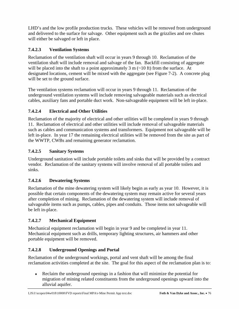
LJS\J:\scopes\04w018\10000\FVD reports\Final MPA\r-Mine Permit App text.doc Foth & Van Dyke and Assoc., Inc. • 76
LHD’s and the low profile production trucks. These vehicles will be removed from underground and delivered to the surface for salvage. Other equipment such as the grizzlies and ore chutes will either be salvaged or left in place. 7.4.2.3 Ventilation Systems Reclamation of the ventilation shaft will occur in years 9 through 10. Reclamation of the ventilation shaft will include removal and salvage of the fan. Backfill consisting of aggregate will be placed into the shaft to a point approximately 3 m (~10 ft) from the surface. At designated locations, cement will be mixed with the aggregate (see Figure 7-2). A concrete plug will be set to the ground surface. The ventilation systems reclamation will occur in years 9 through 11. Reclamation of the underground ventilation systems will include removing salvageable materials such as electrical cables, auxiliary fans and portable duct work. Non-salvageable equipment will be left in-place. 7.4.2.4 Electrical and Other Utilities Reclamation of the majority of electrical and other utilities will be completed in years 9 through 11. Reclamation of electrical and other utilities will include removal of salvageable materials such as cables and communication systems and transformers. Equipment not salvageable will be left in-place. In year 17 the remaining electrical utilities will be removed from the site as part of the WWTP, CWBs and remaining generator reclamation. 7.4.2.5 Sanitary Systems Underground sanitation will include portable toilets and sinks that will be provided by a contract vendor. Reclamation of the sanitary systems will involve removal of all portable toilets and sinks. 7.4.2.6 Dewatering Systems Reclamation of the mine dewatering system will likely begin as early as year 10. However, it is possible that certain components of the dewatering system may remain active for several years after completion of mining. Reclamation of the dewatering system will include removal of salvageable items such as pumps, cables, pipes and conduits. Those items not salvageable will be left in-place. 7.4.2.7 Mechanical Equipment
Mechanical equipment reclamation will begin in year 9 and be completed in year 11. Mechanical equipment such as drills, temporary lighting structures, air hammers and other portable equipment will be removed. 7.4.2.8 Underground Openings and Portal
Reclamation of the underground workings, portal and vent shaft will be among the final reclamation activities completed at the site. The goal for this aspect of the reclamation plan is to:
♦ Reclaim the underground openings in a fashion that will minimize the potential for migration of mining related constituents from the underground openings upward into the alluvial aquifer.

LJS\J:\scopes\04w018\10000\FVD reports\Final MPA\r-Mine Permit App text.doc Foth & Van Dyke and Assoc., Inc. • 77
♦ Remove the vent shaft equipment and seal the vertical opening and aggregate raises for
long term safety and environmental protection.
♦ Reclaim the mine portal and restore the rock face of the outcrop. 7.4.2.8.1 Reclamation of Underground Openings The bedrock characterization work completed by Golder Associates Ltd. (2005b) and Golder Associates, Inc. (2006) has documented two hydrologic characteristics of the bedrock system around the Eagle deposit that are relevant to the reclamation of the underground workings.
♦ The upper bedrock above 335 m MSL is characterized by low permeability bedrock that contains non-saline water.
♦ The lower bedrock below 335 m MSL is characterized by rock that exhibits matrix
permeability and infrequent fracture dominated hydraulic features. In addition, the lower bedrock contains saline water.
♦ There is no pattern of upward vertical hydraulic gradients within the bedrock. Thus there
is little, if any, potential for migration of water in and around the mine up into the alluvial aquifer.
Based on these features and the expected water chemistry of the water in the reflooded underground mine (see Appendix D-5) KEMC is proposing plans for reclaiming the underground openings that will:
♦ Seal the openings so that there is no vertical mining related connections between the upper and lower bedrock.
♦ Accelerate reflooding of the underground openings through two new wells that will pump
water into the mine workings in the upper and lower bedrock (see Figures 7-2 and 7-3 for approximate well locations).
♦ Monitor the workings and surrounding bedrock vertical gradients (see bedrock
piezometer locations on Figure 7-3) to confirm that there is no potential for approximate upward migration of mining related constituents after reflooding is completed.
♦ As a contingency plan, KEMC will leave the WWTP and associated infrastructure in
place for five years after reflooding is complete. If monitoring indicates there is the potential for upward migration of mining related constituents associated with the underground openings, KEMC will pump water out of the upper bedrock workings, treat it at the WWTP and recirculate the treated water back into the upper bedrock workings. This process of flushing the upper bedrock workings with clean water will continue for a period of several years until water quality conditions in the upper workings are protective of groundwater in the regional aquifer. Note this is not a perpetual care contingency.
Figure 7-2 displays a section through the mine workings and denotes the location of backfill aggregate and cemented aggregate that will seal the mine workings as prescribed above. In
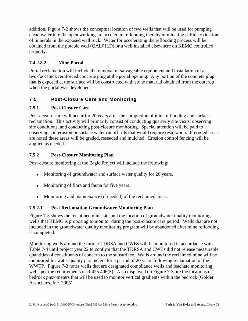
LJS\J:\scopes\04w018\10000\FVD reports\Final MPA\r-Mine Permit App text.doc Foth & Van Dyke and Assoc., Inc. • 78
addition, Figure 7-2 shows the conceptual location of two wells that will be used for pumping clean water into the open workings to accelerate reflooding thereby terminating sulfide oxidation of minerals in the exposed wall rock. Water for accelerating the reflooding process will be obtained from the potable well (QAL011D) or a well installed elsewhere on KEMC controlled property. 7.4.2.8.2 Mine Portal Portal reclamation will include the removal of salvageable equipment and installation of a two-foot thick reinforced concrete plug at the portal opening. Any portion of the concrete plug that is exposed at the surface will be constructed with stone material obtained from the outcrop when the portal was developed. 7.5 Post-Closure Care and Monitoring
7.5.1 Post-Closure Care Post-closure care will occur for 20 years after the completion of mine reflooding and surface reclamation. This activity will primarily consist of conducting quarterly site visits, observing site conditions, and conducting post-closure monitoring. Special attention will be paid to observing soil erosion or surface water runoff rills that would require restoration. If eroded areas are noted these areas will be graded, reseeded and mulched. Erosion control fencing will be applied as needed. 7.5.2 Post-Closure Monitoring Plan Post-closure monitoring at the Eagle Project will include the following:
♦ Monitoring of groundwater and surface water quality for 20 years.
♦ Monitoring of flora and fauna for five years.
♦ Monitoring and maintenance (if needed) of the reclaimed areas. 7.5.2.1 Post Reclamation Groundwater Monitoring Plan
Figure 7-3 shows the reclaimed mine site and the location of groundwater quality monitoring wells that KEMC is proposing to monitor during the post-closure care period. Wells that are not included in the groundwater quality monitoring program will be abandoned after mine reflooding is completed. Monitoring wells around the former TDRSA and CWBs will be monitored in accordance with Table 7-4 until project year 22 to confirm that the TDRSA and CWBs did not release measurable quantities of constituents of concern to the subsurface. Wells around the reclaimed mine will be monitored for water quality parameters for a period of 20 years following reclamation of the WWTP. Figure 7-3 notes wells that are designated compliance wells and leachate monitoring wells per the requirements of R 425.406(5). Also displayed on Figure 7-3 are the locations of bedrock piezometers that will be used to monitor vertical gradients within the bedrock (Golder Associates, Inc. 2006).

LJS\J:\scopes\04w018\10000\FVD reports\Final MPA\r-Mine Permit App text.doc Foth & Van Dyke and Assoc., Inc. • 79
Table 7-4 Post-Reclamation Groundwater Quality Monitoring Program
Parameter List and Sampling Frequency
Parameter Frequency Analytical Method Method
Reporting Limit Units Alkalinity, Bicarbonate Quarterly(1) USEPA-310.1 2.0 mg/l Alkalinity, Carbonate Quarterly(1) USEPA-310.1 2.0 mg/l Aluminum Annual USEPA-6010B 50 ug/l Antimony Annual USEPA-6020 5.0 ug/l Arsenic Quarterly(1) USEPA-6020 2.0 ug/l Barium Annual USEPA-6020 20 ug/l Beryllium Annual USEPA-6020 1.0 ug/l Boron Quarterly(1) USEPA-6010B 100 ug/l Cadmium Annual USEPA-6020 0.50 ug/l Calcium Annual USEPA-6010B 0.50 mg/l Chloride Quarterly(1) USEPA-325.2 1.0 mg/l Chromium Annual USEPA-6020 5.0 ug/l Cobalt Annual USEPA-6010B 10 ug/l Copper Quarterly(1) USEPA-6020 5.0 ug/l Fluoride Annual APHA 4500-F C 0.10 mg/l Iron Quarterly(1) USEPA-6010B 20 ug/l Lead Annual USEPA-6020 1.0 ug/l Lithium Annual USEPA-6010B 8.0 ug/l Magnesium Annual USEPA-6010B 0.50 mg/l Manganese Quarterly(1) USEPA-6010B 20 ug/l Mercury Quarterly(1) USEPA-1631E 0.25 ng/l Molybdenum Annual USEPA-6020 10 ug/l Nickel Quarterly(1) USEPA-6020 25 ug/l Nitrate Quarterly(1) USEPA-353.2 0.05 mg/l Potassium Annual USEPA-6010B 0.50 mg/l Selenium Quarterly(1) USEPA-6020 1.0 ug/l Silver Annual USEPA-6020 0.20 ug/l Sodium Quarterly(1) USEPA-6010B 0.50 mg/l Sulfate Quarterly(1) USEPA-375.4 2.0-5.0 mg/l Strontium Annual USEPA-6010B 50 ug/l Thallium Annual EPA-200.8/6020 2 ug/l Vanadium Annual EPA-200.8/6020 10 ug/l Zinc Annual USEPA-6020 10 ug/l Redox Quarterly(1) Field NA meV Field pH Quarterly(1) Field NA su Groundwater Elevation Quarterly(1) Field NA ft MSL Specific Conductance Quarterly(1) Field NA umhos/cm Temperature Quarterly Field NA oC Dissolved Oxygen Quarterly(1) Field NA mg/l
(1) After project year 27, parameters will be analyzed on an annual basis. Prepared by: SVD1
Checked by: JSK

LJS\J:\scopes\04w018\10000\FVD reports\Final MPA\r-Mine Permit App text.doc Foth & Van Dyke and Assoc., Inc. • 80
7.5.2.2 Post Reclamation Surface Water Quality Monitoring Plan Figure 7-4 shows the location of surface water monitoring stations that KEMC will use to monitor surface water quality during the 20-year post-closure care period. These monitoring stations will be sampled in accordance with the parameter and frequency list contained in Table 7-5. 7.5.2.3 Biological Monitoring KEMC will continue the operational biological monitoring program described in Section 6 for a period of five years after reflooding of the underground mine. 7.5.2.4 Sampling Protocols The sampling procedures and statistical methods used in the operational monitoring plan will continue to be used during the post-closure monitoring period.

LJS\J:\scopes\04w018\10000\FVD reports\Final MPA\r-Mine Permit App text.doc Foth & Van Dyke and Assoc., Inc. • 81
Table 7-5 Post Reclamation Surface Water Quality Monitoring Program
Parameter List and Sampling Frequency
Parameter Frequency Analytical Method Method
Reporting Limit Units Field Temperature Quarterly Field NA oC D.O. Quarterly Field NA mg/l Specific Conductance Quarterly Field NA umhos/cm pH Quarterly Field NA su Metals Aluminum Annual EPA-200.7/6010B 50 ug/l Lithium Annual EPA-200.7/6010B 10 ug/l Antimony Annual EPA-200.8/6020 2.0 ug/l Arsenic Quarterly(1) EPA-200.8/6020 1.0 ug/l Barium Annual EPA-200.8/6020 10 ug/l Iron Quarterly(1) EPA-200.7/6010B 20 ug/l Beryllium Annual EPA-200.8/6020 1.0 ug/l Boron Quarterly(1) EPA-200.8/6020 50 ug/l Cadmium Annual EPA-200.8/6020 0.2 ug/l Chromium Annual EPA-200.8/6020 1.0 ug/l Copper Quarterly(1) EPA-200.8/6020 1.0 ug/l Cobalt Quarterly(1) EPA-200.8/6020 10 ug/l Lead Annual EPA-200.8/6020 1.0 ug/l Manganese Quarterly(1) EPA-200.8/6020 10 ug/l Molybdenum Annual EPA-200.8/6020 10 ug/l Nickel Quarterly(1) EPA-200.8/6020 1.0 ug/l Selenium Quarterly(1) EPA-200.8/6020 2.0 ug/l Silver Annual EPA-200.8/6020 0.2 ug/l Zinc Annual EPA-200.8/6020 10 ug/l Mercury Quarterly(1) EPA-1631E 0.25 ng/l Anions Alkalinity, Bicarbonate Annual 310.1/SM 2320 B 2.0 mg/l Alkalinity, Carbonate Annual 310.1/SM 2320 B 2.0 mg/l Chloride Annual 325.2/4500-CL E 1.0 mg/l Fluoride Annual SM 4500 F-C 0.10 mg/l Nitrate-N Annual 353.2/4500 NO3F 0.05 mg/l Sulfate Quarterly(1) EPA-375.4/9038 1.0 mg/l Cations Calcium Annual EPA-200.7/6010B 0.50 mg/l Potassium Annual EPA-200.7/6010B 0.50 mg/l Magnesium Annual EPA-200.7/6010B 0.50 mg/l Sodium Annual EPA-200.7/6010B 0.50 mg/l Total Dissolved Solids Quarterly(1) EPA-160.1 50 mg/l
(1) After project year 27, parameters will be analyzed on an annual basis.
Prepared by: SVD1 Checked by: JSK

LJS\J:\scopes\04w018\10000\FVD reports\Final MPA\r-Mine Permit App text.doc Foth & Van Dyke and Assoc., Inc. • 82
7.6 Reclamation Costs
Total estimated reclamation cost for the Eagle Project is $6,738,050, including a 10% contingency. Included with this cost is $1,415,000 for post-closure monitoring. Reclamation line item costs are provided in Table 7-6. The summary reclamation cost is presented in Table 7-7. The unit costs are based upon “Means Building Construction Cost Data” or engineering judgment from experience, assuming a third party would perform the work. The unit costs include labor, materials, and overhead and profit.

LJS\J:\scopes\04w018\10000\FVD reports\Final MPA\r-Mine Permit App text.doc Foth & Van Dyke and Assoc., Inc. • 83
Table 7-6 Reclamation and Monitoring Cost Estimate
Item Unit Cost/Unit Extension
Years 1 and 2 (Site Construction) 1. Regrading 16 ac $1,000/ac $16,000 2. Install Erosion Control Devices (silt fence) 4,000 lf $2/lf $8,000 3. Seed/Mulch 16 ac $2,500/ac $40,000 4. Plantings (trees/shrubs) 80 $100/planting $8,000
Annual Cost $72,000 Year 8 (TDRSA)
1. TDRSA Removal ♦ Remove Salvageable Materials
Lump Sum $5,000
♦ Remove 12” Drainage Layer 10,000 yd3 $3.50/ yd3 $35,000 ♦ Remove Geosynthetic Components
(HDPE/GCL/Geotextile) each Lump Sum $10,000
2. Regrade Area 145,000 yd3 $3/ yd3 $435,000 3. Topsoil 6 acres $2,000/ac $12,000 4. Install (silt fence) 2,500 lf $2/lf $5,000 5. Seed/Fertilize/Mulch 6 acres $2,500/ac $15,000
Annual Cost $517,000 Year 9 (Closure)
1. Remove Salvageable Materials from Buildings
-- Lump Sum $25,000
2. Remove Site Utilities -- Lump Sum $25,000 3. Demolish Buildings 10 structures $6,000 $60,000 4. Dispose of Regulated Materials 2,000 tons $40/ton $80,000 5. Parking Lot Removal 7,000 sy $4/sy $28,000 6. Fence Removal 11,500 lf $2/lf $23,000 7. Regrading of Basins 3 & 4 34,000 yd3 $3/ yd3 $102,000 8. Regrade Building Sites 3 acres $1,000/ac $3,000 9. Seed/Mulch Disturbed Areas 10 acres $2,500/ac $25,000 10. Install Silt Fence 2,000 lf $2/lf $4,000
Annual Cost $375,000 Year 10 (Closure)
1. Remove Surface Salvageable Materials Lump Sum $50,000 2. Backfill Surface Raises and Cap 6,000 yd3 $12/ yd3 $72,000 3. Install Mine Plugs 1,000 $100/ yd3 $100,000 4. Remove Site Utilities -- Lump Sum $150,000 5. Demolish Buildings (completed) -- Lump Sum $100,000 6. Dispose of Regulated Materials 500 tons $40/ton $20,000 7. Regrade Building Sites 10 acres $1,000 $10,000 8. Seed/Mulch Disturbed Areas 20 acres $2,500 $50,000 9. Install Erosion Control Devices (silt fencing) 2,000 lf $2/lf $4,000 10. Backfill Mine Portal 15,300 yd3 $12/ yd3 $184,000 11. Remove Salvageable Materials from
Underground -- Lump Sum $100,000 12. TDRSA Backfilling 250,000 yd3 $3.50/ yd3 $875,000 13. Backfilling Stopes(1) 50,000 yd3 $20/yd3(2) 1,000,000 14. Install Reflooding Wells -- Lump Sum $50,000
Annual Cost $2,765,000 Year 11 Closure
1. Regrading of remaining disturbed areas 10 acres $1,000/acre $10,000 2. Seed/mulch disturbed areas 10 acres $2,500/acre $25,000 3. Install erosion control devices (silt fencing) 2,000/lf $2/lf $4,000
Annual Cost $39,000
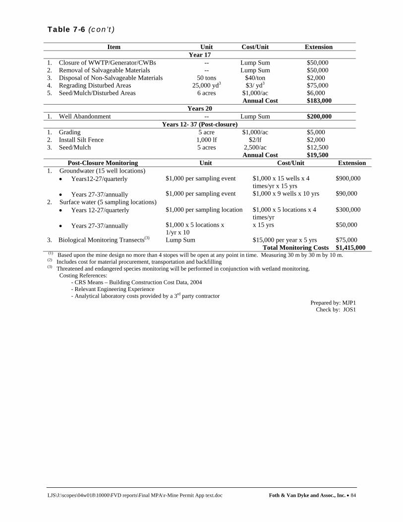
Table 7-6 (con’t)
LJS\J:\scopes\04w018\10000\FVD reports\Final MPA\r-Mine Permit App text.doc Foth & Van Dyke and Assoc., Inc. • 84
Item Unit Cost/Unit Extension Year 17
1. Closure of WWTP/Generator/CWBs -- Lump Sum $50,000 2. Removal of Salvageable Materials -- Lump Sum $50,000 3. Disposal of Non-Salvageable Materials 50 tons $40/ton $2,000 4. Regrading Disturbed Areas 25,000 yd3 $3/ yd3 $75,000 5. Seed/Mulch/Disturbed Areas 6 acres $1,000/ac $6,000
Annual Cost $183,000 Years 20
1. Well Abandonment -- Lump Sum $200,000 Years 12- 37 (Post-closure)
1. Grading 5 acre $1,000/ac $5,000 2. Install Silt Fence 1,000 lf $2/lf $2,000 3. Seed/Mulch 5 acres 2,500/ac $12,500
Annual Cost $19,500 Post-Closure Monitoring Unit Cost/Unit Extension
1. Groundwater (15 well locations) • Years12-27/quarterly
• Years 27-37/annually
$1,000 per sampling event $1,000 per sampling event
$1,000 x 15 wells x 4 times/yr x 15 yrs $1,000 x 9 wells x 10 yrs
$900,000 $90,000
2. Surface water (5 sampling locations) • Years 12-27/quarterly • Years 27-37/annually
$1,000 per sampling location $1,000 x 5 locations x 1/yr x 10
$1,000 x 5 locations x 4 times/yr x 15 yrs
$300,000 $50,000
3. Biological Monitoring Transects(3) Lump Sum $15,000 per year x 5 yrs $75,000 Total Monitoring Costs $1,415,000
(1) Based upon the mine design no more than 4 stopes will be open at any point in time. Measuring 30 m by 30 m by 10 m. (2) Includes cost for material procurement, transportation and backfilling (3) Threatened and endangered species monitoring will be performed in conjunction with wetland monitoring.
Costing References: - CRS Means – Building Construction Cost Data, 2004 - Relevant Engineering Experience - Analytical laboratory costs provided by a 3rd party contractor
Prepared by: MJP1 Check by: JOS1
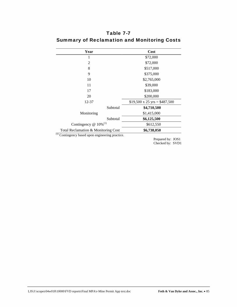
LJS\J:\scopes\04w018\10000\FVD reports\Final MPA\r-Mine Permit App text.doc Foth & Van Dyke and Assoc., Inc. • 85
Table 7-7
Summary of Reclamation and Monitoring Costs
Year Cost 1 $72,000 2 $72,000 8 $517,000 9 $375,000
10 $2,765,000 11 $39,000 17 $183,000 20 $200,000
12-37 $19,500 x 25 yrs = $487,500 Subtotal $4,710,500
Monitoring $1,415,000 Subtotal $6,125,500
Contingency @ 10%(1) $612,550 Total Reclamation & Monitoring Cost $6,738,050
(1) Contingency based upon engineering practice. Prepared by: JOS1 Checked by: SVD1

LJS\J:\scopes\04w018\10000\FVD reports\Final MPA\r-Mine Permit App text.doc Foth & Van Dyke and Assoc., Inc. • 86
8 Contingency Plan This section of the Mining Permit Application addresses contingency plan requirements defined in R 425.205. This includes a qualitative assessment of the risk to public health and safety or the environment (HSE risks) associated with potential accidents or failures involving activities with the Eagle Project. Engineering or operational controls to protect human health and the environment are discussed in Section 4 and Section 5 of this document. The focus of this contingency plan is on possible HSE risks and contingency measures. Possible HSE risks to on-site workers will be addressed by KEMC through HSE procedures in accordance with Occupational Safety and Health Administration (OSHA) and Mine Safety and Health Administration (MSHA) requirements. The Eagle Project involves mining ore, as well as storing and treating by-products of that process. KEMC’s mining, storage and treatment facilities have been designed, and will be constructed and operated, to protect the environment through the use of proven technologies and engineering practices. The environmental protection features are discussed in Section 4 and Section 5. 8.1 Contingency Items
This contingency plan addresses the items listed below in this Section in accordance with R 425.205 (1)(a)(i) - (xii).
♦ Release or threat of release of toxic or acid-forming materials ♦ Storage, transportation and handling of explosives ♦ Fuel storage and distribution ♦ Fires ♦ Wastewater collection and treatment system ♦ Air emissions ♦ Spills of hazardous substances ♦ Other natural risks defined in the EIA ♦ Power disruption ♦ Unplanned subsidence, and ♦ Leaks from containment systems for stockpiles or disposal and storage facilities. ♦ Basin berm failures.
For each contingency item, a description of the risk is provided, followed by a qualitative assessment of the risk(s) to the environment or public health and safety. Next, the response measures to be taken in the event of an accident or failure are described. 8.1.1 Release of Toxic or Acid-Forming Materials Potentially reactive materials generated as a result of mining operations include the ore and development rock. As discussed in Section 4, both the development rock and ore have the potential to leach mining related constituents when exposed to air and water. As described in the following sub-sections, handling and temporary storage of both the ore and development rock have been carefully considered in the design of the Eagle Project so as to prevent the uncontrolled release of ARD. On-site beneficiation of ore from the Eagle Project is limited to primary crushing prior to transporting by truck to an off-site railhead and from the railhead to an
LJS\J:\scopes\04w018\10000\FVD reports\Final MPA\r-Mine Permit App text.doc Foth & Van Dyke and Assoc., Inc. • 87
off-site mill for secondary processing. Therefore, the only chemical reagents used on-site are associated with the WWTP, and are discussed in Section 8.1.5. 8.1.1.1 Coarse Ore Storage Area Coarse ore from the underground mine will be trucked to the surface and placed in the COSA. The COSA will be a three-sided building with a full roof that is used for temporary storage of stockpiled coarse ore. The COSA will have a concrete floor that will be sloped to a floor drain that will collect any contact water associated with the ore. This contact water will be drained or pumped into the composite lined CWB where it is stored until treatment at the wastewater treatment plant. Contingency measures associated with the CWB liner systems are discussed in Section 8.1.12. 8.1.1.2 Temporary Development Rock Storage Area Development of the mine begins with excavation of surrounding rock to provide access to the ore body through portals, raises and ramps. This surrounding rock is known as “development rock.” At the beginning of mining, the development rock from these excavations will be temporarily stored at the surface in the TDRSA, since adequate space will not be available underground until additional ore has been removed. As mining progresses, additional development rock will be mined and will be returned underground to backfill areas where the ore has been removed. Most of the development rock will be inert while stored on the surface, posing no threat to the environment. Ongoing tests show some of this rock has the potential to oxidize when exposed to air and water over longer periods of time. Therefore, KEMC will handle the development rock in a way to minimize the potential formation of ARD, and if formed, prevent it from being released into the environment. Accordingly, KEMC has designed a state-of-the-art TDRSA to contain the development rock. As discussed in Section 5, the TDRSA will be constructed of the following components to minimize the potential generation of ARD, and if formed, prevent it from being released to the environment:
♦ A composite liner system comprised of a geomembrane liner underlain by a GCL. ♦ A water collection system over the composite liner to collect precipitation that comes in
contact with development rock. The collection system also helps protect the geomembrane from damage by the development rock. The collection system will consist of a geocomposite drainage fabric overlain by a 12-in thick granular drainage layer sloping towards the collection sump.
♦ A leak detection system for early detection and collection of potential percolation through
the composite liner system. The leak detection system includes a collection sump, and a sump pump for liquid removal.
♦ A geomembrane cover system placed over the development rock.
LJS\J:\scopes\04w018\10000\FVD reports\Final MPA\r-Mine Permit App text.doc Foth & Van Dyke and Assoc., Inc. • 88
When development rock is placed in the TDRSA it will be amended with high-calcium limestone as an additional contingency measure to offset the formation of ARD. Moreover, the development rock will be covered to further limit the generation of ARD by minimizing contact with precipitation. After approximately seven years, the development rock will be returned underground as mine backfill. The short term nature of this project significantly reduces the potential for release of toxic and acid-forming materials. If the water that comes in contact with the development rock does become acidic, it will not be exposed to the environment due to the design of the TDRSA. Further, all contact water from the TDRSA will be collected and treated at the WWTP. Contingency actions associated with potential water basin berm failures are discussed in Section 8.1.6. The contingency actions that address potential failure of the liner contact water collection system are discussed in Section 8.1.12. 8.1.1.3 Ore Transportation The ore will be loaded from the ore storage bins into tractor-trailer trucks and transported to a railhead location. All loaded ore trucks will have the tires, sides and undercarriages washed at the on-site truck wash prior to leaving the site. In addition, KEMC is continuing to study available transportation routes and railhead locations. Presently the following route is proposed for moving the ore from the Eagle Project site to the railhead:
♦ East on Triple A Road 9.0 miles to CR 510. ♦ East on CR 510 3.0 miles to CR 550. ♦ South on CR 550 approximately 20 plus miles to a railhead in the vicinity of Marquette.
The trucks will be covered end-dump units with a length limit of 60 ft. The truck will handle 50-52 tons per load on average. During seasonal weight restrictions designated by the Marquette County Road Commission (MCRC) loads would be reduced to a 65% load at approximately 33 tons/load. Ore will be trucked to the railhead and loaded into an enclosed bulk ore storage building. Ore will be loaded onto rail cars with a front end loader from inside the building and shipped via the CN rail line to an off-site processing facility. KEMC will work with the MCRC on proposed improvements to Triple A Road and CR 510 to minimize the potential for adverse effects from the additional traffic. These improvements will consist of upgrading the surface and improving drainage from the road. Currently, drainage from some sections of the Triple A Road is marginal with ponding in some areas during periods of high rainfall and snowmelt. It is envisioned that improvements would include enhancing key areas of soft subgrade by a combination of undercut and backfill, building up the roadway to include an all-weather gravel surface and adding culverts and ditching to improve drainage. Improving the road surface and drainage on these two roads will reduce the dust and sediment runoff that is currently produced by traffic. Safety will also be improved as the improvements will make the road easier to travel and improved drainage will reduce puddles during storm events or spring melt, and ice during the winter. In addition, KEMC will work with MCRC to maintain a safe road surface for employees, vendors and ore shipping. Potential truck accidents are possible while transporting ore from the mine site to the railhead site. In the event of a truck roll over, ore could be spilled onto the road and adjacent areas. Since the coarse ore is a crushed rock sized material, it will be relatively easy to pick the material

LJS\J:\scopes\04w018\10000\FVD reports\Final MPA\r-Mine Permit App text.doc Foth & Van Dyke and Assoc., Inc. • 89
up with conventional earthmoving equipment and place the ore back into a truck or railcar. If such an event should occur, removal action would take place as soon as possible. Although geochemical testing of the ore has shown that ARD will not occur in this short of a time period, it will be important to respond appropriately to any spills. If the accident results in spillage of ore into a water body, specialized equipment such as temporary dams/cofferdams and large backhoes may be required to remove the material from the water. The railhead facility will be designed such that all loading and unloading of ore will occur in an enclosed building with a concrete floor. These features will prevent release of dust and prevent precipitation from contacting the ore. Once the ore is loaded onto the rail cars, the rail cars will be covered during transportation to the off-site processing facility. 8.1.2 Storage, Transportation and Handling of Explosives Blasting agents or explosives will be required for blasting operations in the development and operation of the mine. The most likely explosives to be used are emulsions of ammonium nitrate/fuel oil (ANFO). Although uncommon, accidental detonation of explosives could result from impact, shock, fire, or electrical discharge. The entire surface operations are located within a fenced area. Vehicular access to the Eagle Project will be controlled by a gate house and the fence system. The storage, transportation, and use of explosives will comply with applicable MSHA standards. Ammonium nitrate and fuel oil will be stored separately. Explosives stored on the surface will be in an isolated magazine located at a secure site at the mine facility. Magazine construction will comply with appropriate codes. Caps, primers, and detonating cord will be stored in a separate magazine. The only access to the magazine area is via a dedicated road from the main facility. Explosives will be transported by a clearly marked truck to the mine portal for distribution and use in the mine. The main impacts of an uncontrolled explosion on the surface would be in the immediate area of the explosion and would include direct injury from the blast zone, falling debris, fire, and the release of combustion products. Combustion products expected from the explosives are carbon monoxide and nitrogen oxides. Neither of these products is expected to be generated in high enough concentrations for significant above ground or off-site exposures to occur. Dust could also be generated but would likely settle to the ground before migrating beyond the Eagle Project site. Uncontrolled underground explosions have not been considered since the environmental effects would not be different from controlled explosions in normal mine operations. In the event of a surface explosion, the Emergency Procedure will be followed, as discussed in Section 8.2. 8.1.3 Fuel Storage and Distribution The fuel storage facility will be located within a fenced and secured area and will contain three diesel fuel storage tanks having an approximate capacity of 20,000 gallons each, all located within a secondary containment system. Fuel storage will also include one smaller tank for regular unleaded gasoline. A building containing diesel fueled generators will be located south of the fuel storage tanks. Propane storage of an approximate capacity of 24,000 gallons will be

LJS\J:\scopes\04w018\10000\FVD reports\Final MPA\r-Mine Permit App text.doc Foth & Van Dyke and Assoc., Inc. • 90
located within the secure area of the mine property adjacent to a building that will contain a propane-fired air heating system for the mine. In general, fuel spills and leaks will be minimized by the following measures:
♦ Training of personnel responsible for hauling fuel in proper procedures and emergency response,
♦ Regular equipment inspections and documentation of findings, and
♦ Adequate secondary containment around all above ground tanks, and
♦ Staging of on-site emergency response equipment to quickly respond to unanticipated
spills or leaks. Specific procedures will be prepared as part of the project’s SPCC Plan. As noted in Section 4.3.18, this plan will be incorporated in a complete PIPP for the entire site. Diesel fuel, gasoline and propane (fuels) will be transported to the Eagle Project by tanker truck from local petroleum distributors. The probability of an accidental release during transportation will be dependant on the location of the supplier(s) and the frequency of shipment, neither of which have been determined. A fuel release resulting from a vehicular accident during transportation is judged to be a low probability event. Transport of fuel in tanker trucks does not pose an unusual risk to the region since tanker trucks currently travel to the region on a regular basis to deliver fuels to gasoline stations located in the communities surrounding the Eagle Project. Three potential release events associated with the surface-stored fuels are a bulk tank failure, mishandling/leaking hoses, and a construction/reclamation phase release. Bulk Tank Failure - A tank failure could potentially result from unusual thermal, mechanical, or chemical stresses. Chemical stresses are not anticipated as the storage tanks will be constructed of materials compatible with the fuels. Mechanical stress is also not anticipated since the tanks will be located within a bermed area offering protection from vehicles. During construction, tanker fuel trucks designed for fueling will be used. Contingency measures required to mitigate a fuel spill will be developed in the PIPP that will be developed prior to construction. In addition, tank integrity testing will be performed at regular frequencies to verify that the storage tanks are not leaking. Mishandling/Leaking Hoses - A release might result from leaking hoses or valves, or from operator mishandling. This type of release is likely to be small in volume and is judged to be a low probability event given that operators will be trained to manage these types of potential releases. These small spills will be cleaned up by using on-site spill response equipment such as absorbent materials and/or removing impacted soils. Construction/Reclamation Phase Release - A major fuel spill during the construction or reclamation phases could occur from a mobile storage tank failure or mishandling of fuels. Such a release is also considered to be a low probability event given that operators will be trained to

LJS\J:\scopes\04w018\10000\FVD reports\Final MPA\r-Mine Permit App text.doc Foth & Van Dyke and Assoc., Inc. • 91
manage these types of potential releases. As with mishandling or leaking hoses, these small spills will be cleaned up by using on-site spill response equipment such as absorbent materials and/or removing impacted soils. Absorptive materials may be used initially to contain a potential spill. After the initial response, soil impacted with residual fuel would be addressed. Remedial efforts could include, if necessary, the removal of soil to preclude migration of fuel to groundwater or surface water. The project's PIPP plan will address fueling operations, fuel spill prevention measures, inspections, training, security, spill reporting, and equipment needs. All responses to a fuel spill, both large and small, will follow the guidelines dictated by the spill response plan. The tanks will be inspected regularly, and records of spills will be kept and reported to MDEQ and other agencies as required. In the unlikely event of a massive tank failure, secondary containment is incorporated into the design with significant capacity to contain the entire contents of the largest single tank plus sufficient freeboard to contain a 24-hour, 25-year rain event. The contained fuel would then be removed by pumping to portable tanks. The tanks will be covered with a roof to minimize accumulation of precipitation inside the secondary containment. In the event of a release, fuels would be adsorbed by soil, retarding their migration. Exposures to contaminated groundwater are not expected because of regulatory requirements for timely and effective response actions which will dictate soil or source removal before migration to groundwater takes place. A transportation-related fuel spill resulting from a non-traffic accident is considered a low probability event. Therefore, the risk of a fuel spill from a non-traffic accident is judged to be minor. Contingency plans for responding to fuel spills from tanker trucks are required of all mobile transport owners as dictated by Department of Transportation (DOT) regulation 49 CFR 130. These response plans require appropriate personnel training and the development of procedures for timely response to spills. The plan must identify who will respond to the spill and describe the response actions to potential releases, including the complete loss of cargo. The plan must also list the names and addresses of regulatory contacts to be notified in the event of a release. 8.1.4 Fires This section discusses contingency measures to be taken in the event of either an underground mine fire or surface fires. 8.1.4.1 Mine Fire
One potential source of combustion could occur during the handling of combustible minerals in the Eagle Project ore body. The ore body contains certain quantities of pyrrhotite, which is an iron sulfide mineral. Iron sulfide is considered to be a phyrophoric material that oxidizes exothermically when exposed to air. Due to the exothermic reaction, ignition can occur, especially if the surface area is increased with the occurrence of finely divided material. This situation is often encountered in a petroleum refinery, where finely divided iron sulfide scales form in refinery units in oxygen deficient atmospheres. When subsequently exposed to air, these crystals of iron sulfide oxidize rapidly back to iron oxide. While this condition can also occur in

LJS\J:\scopes\04w018\10000\FVD reports\Final MPA\r-Mine Permit App text.doc Foth & Van Dyke and Assoc., Inc. • 92
underground mines, this problem should be adequately controlled through proper mine ventilation. In the event that a mine fire develops it would be expected to be localized, short lived, and would not pose a threat to the workers or the environment. Off-site populations would not be exposed to agents resulting in adverse effects. Events that do not result in exposure cannot result in health effects and do not pose a risk. Mine fires, therefore, pose a negligible risk. Appropriate preventative and contingency measures will be exercised as required by MSHA. These measures include the installation of fire suppression systems, the widespread distribution of fire extinguishers throughout the mine, employee safety training programs, and the use of a mine rescue team trained in firefighting techniques. Mine evacuation procedures, as discussed in Section 8.2, may be invoked, depending on the nature and extent of an underground fire. 8.1.4.2 Surface Fire Surface fires can be started by a variety of causes including vehicular accidents, accidental ignition of fuels or flammable chemical reagents, and lightening strikes. Smoking will only be allowed in designated areas on the site. Contingency measures include having the required safety equipment, appropriate personnel training and standard operating procedures. Given these measures, uncontrolled or large surface fires are considered a low probability event with negligible risk. Because the Eagle Project is situated in a forested region, forest fires started off-site could potentially impact the mine site. The cleared area in the vicinity of the surface facilities and excess soil berms will serve as a fire break to protect surface facilities. Contingency measures discussed below can be implemented in the event of an off-site forest fire. In order to minimize the risk of a fire on-site, stringent safety standards will be followed during construction and operation of surface facilities. During the construction phase, a water truck will be stationed on-site and all construction equipment will be equipped with fire extinguishers. If controlled burning is required to eliminate waste wood following site clearing activities, a permit will be obtained from the MDNR which would specify measures to be taken for the prevention of fires. During the plant operation phase, standard fire safety measures will be exercised. Fire extinguishers and standby water pipelines will be located in high risk areas and personnel will be trained in their use. The surface rescue team will be trained in fire fighting techniques to respond to fires. On-site fire fighting equipment will include a fire control vehicle and an above ground water storage tank and distribution system for fire suppression. 8.1.5 Wastewater Collection and Treatment The major sources of water requiring treatment are groundwater inflow to the mine, contact water from the TDRSA and storm water runoff from the operations area. These waters will be treated at the WWTP and returned to the subsurface at the TWIS per the Groundwater Discharge Permit for the project.

LJS\J:\scopes\04w018\10000\FVD reports\Final MPA\r-Mine Permit App text.doc Foth & Van Dyke and Assoc., Inc. • 93
The basic treatment processes for the facility include filtration, hydroxide precipitation, reverse osmosis, ion exchange and evaporation. Solids generated from the WWTP will be disposed of in accordance with applicable regulations. All non-sanitary wastewater generated at the Eagle Project will be routed to CWBs No.1 and No.2. These basins will provide wastewater storage and equalization capacity. Wastewater will be pumped from these basins to the WWTP. The wastewater treatment system will be designed to handle various process upset conditions such as power disruption (Section 8.1.10) or maintenance of the various process units. The wastewater effluent will be continually monitored for key indicator parameters to verify the proper operation. Effluent not meeting treatment requirements will be pumped back to the CWBs for re-treatment. The CWBs are designed to hold 14 days of mine drainage water. This 14-day storage capacity of the CWBs will allow sufficient time to correct the process upset condition. Potential hazards and chemical reagents associated with the WWTP are discussed in Section 8.1.8. 8.1.5.1 Contact Water Basins The CWBs are very conservatively designed to handle peak snow melt and rain events that exceed the 100-yr, 24-hr precipitation event. The CWBs has also been designed with the following contingencies:
♦ The CWBs are designed to hold 14 days of mine drainage water allowing sufficient time for maintenance of WWTP equipment.
♦ In the unlikely event that a runoff event exceeds capacity of the CWBs, excess water will
be routed to the composite-lined TDRSA for emergency temporary storage.
♦ As an additional contingency, water can be pumped into vacant underground mine workings for additional temporary storage of water in the event ample storage is not available at the TDRSA. This is considered an extremely unlikely condition given the very conservative design of the CWBs.
Potential release events associated with breach of the composite liner, and overtopping of the berms are discussed in Section 8.1.6. Potential leakage of the liner system is discussed in Section 8.1.12. 8.1.5.2 Non-Contact Storm Water Storm water runoff from the non-contact areas will be directed to one of four NCWIBs. The NCWIBs allows runoff from non-contact areas to infiltrate through the on-site sandy soils. In general, the NCWIBs have been designed such that no runoff is expected to leave the disturbed areas of the site. The NCWIBs are very conservatively sized to accommodate the same runoff event as the CWBs. As an additional conservative design measure, the CWBs have been sized assuming the ground is frozen 6 months out of the year with no infiltration during this time period. In the event that the infiltration capacity of the CWB soils is reduced over time by the presence of silt, the solids will be removed to restore the infiltration capacity. As a final contingency measure, the CWBs

LJS\J:\scopes\04w018\10000\FVD reports\Final MPA\r-Mine Permit App text.doc Foth & Van Dyke and Assoc., Inc. • 94
have been designed with an emergency overflow structure that will have an industrial storm water discharge permit from the MDEQ. 8.1.5.3 Treated Water Infiltration System Treated water will be piped from the WWTP to the TWIS in a buried pipeline. The treated water will be discharged to the on-site sandy soils through the TWIS. The TWIS will be located in highly permeable soil. The treated effluent will be applied evenly within individual infiltration cells and discharged to groundwater. The treated effluent will be applied to the TWIS through five separate infiltration cells. This design will allow at least one cell to be out of service for resting and/or maintenance while the other cells are being used. Potential failure mechanisms of the TWIS include reduced infiltration capacity, pipe breakage and frost damage. The infiltration capacity of the TWIS is designed with a capacity that is greater than the capacity of the WWTP. In the unlikely event that the infiltration capacity becomes reduced over time, additional capacity could be constructed adjacent to the proposed footprint. If pipe breakage occurs, the damaged sections will be removed and replaced. Frost is not expected to be a problem. As a contingency against frost damage, the TWIS will be used for stockpiling some of the excess topsoil stripped from the site. This five feet of additional soil cover will preclude frost penetration to the depth of the infiltration zone. 8.1.6 Berm Failures This section discusses contingency actions to be taken in the event of berm failures at the CWBs and TDRSA. Liner failures are discussed in Section 8.1.12. Embankment failure of the CWBs or the TDRSA is not likely due to the very small height of the embankments, and the flat slopes and the stable nature of the onsite foundation soils at the site. Due to the short embankment height and excellent foundation soils on-site, berm failure is a very nominal risk. In addition, all construction will be under strict QA/QC procedures to verify good construction of the embankments. Overtopping of the CWBs is also very unlikely due to 2 ft freeboard above an already very conservative design. In addition, in the event of a catastrophic flood event, the TDRSA will be used for excess water storage. Erosion on the external berm slopes could be caused by unusually high precipitation. Erosion control contingency measures will be to quickly repair potential rutting or other soil instability with conventional earth moving equipment. 8.1.7 Air Emissions The construction, operation and reclamation phases of the project will be performed in a manner to minimize the potential for accidents or failures that could result in off-site air quality impacts. All phases of the project will incorporate a combination of operating and work practices, maintenance practices, emission controls and engineering design to minimize potential accidents or failures. Below is a description of identified areas of risk and associated contingency measures that may be required. As part of a comprehensive environmental control plan, these contingency measures will assist in minimizing air impacts to the surrounding area.

LJS\J:\scopes\04w018\10000\FVD reports\Final MPA\r-Mine Permit App text.doc Foth & Van Dyke and Assoc., Inc. • 95
8.1.7.1 Fugitive Emissions During Construction During surface construction, areas subject to cut and fill operations and development of soil stockpiles will be temporarily re-vegetated and/or covered after final grading for soil stabilization and dust control. Temporary re-vegetation will start during the first year and continue through the completion of construction. After final grading of embankment slopes, temporary or permanent vegetation will be planted for soil stabilization and to reduce wind blown dust. While these soil stabilization efforts are expected to be effective, there is a potential that excessive dust could be created by extreme weather conditions. These conditions could include strong wind storms or gusts in the area or excessive rain events. Such events could erode soil and vegetation, creating newly exposed soil that could also be subject to wind dispersion. To address this risk, KEMC will closely monitor re-vegetated and covered areas during the construction phase. If vegetated or covered areas are disturbed by wind activity or excessive rainfall, protective mats and/or vegetation will be re-established as soon as possible. Temporary covers may also need to be re-anchored to ensure temporary stockpiles are protected. In addition to the above situation, there may be periods when hot and/or dry conditions could occur during the construction phase. To the extent necessary during these periods, roadways will be kept moist by instituting a watering program over identified traffic areas. It is anticipated this program will minimize excessive dust associated with mobile equipment. In the event fugitive dust is still identified as an issue, the cause of the problem will be determined such that appropriate action can occur. 8.1.7.2 Air Emissions During Operations During operation of the mine, potential emissions from the facility will be controlled as detailed in the project’s Michigan Air Use Permit – Permit to Install Application (Foth & Van Dyke, 2005a). These controls will include implementation of an on-site roadway watering program, use of building enclosures or flexible membrane covers on storage areas, installation of dust collection or suppression systems such as a baghouse, wet scrubber or water sprays to control dust during ore crushing and following prescribed preventive maintenance procedures for the facility. Crushed ore that is moved off-site will be transported in covered trucks to minimize dust emissions. Below is a more detailed discussion of potential airborne risks associated with proposed operations at the facility. During facility operations, KEMC will utilize certain pieces of mobile equipment to move crushed ore materials about the site. Equipment will include ore production trucks, front end loaders, product haul trucks and miscellaneous delivery trucks. To control dust emissions during movement of these vehicles across the site during dry periods, a comprehensive on-site watering program has been developed to control these potential fugitive sources of dust. While the watering program will be closely monitored, if excessive dust emissions should occur, the facility will take appropriate corrective action, which could include intensifying and/or adjusting the watering program to properly address the problem. To minimize dust emissions from development rock, coarse ore and crushed ore storage areas, such areas will either be fully or partially enclosed. Materials will be moved to and from these areas during the course of operations. Given the relatively large size of these materials, it is anticipated that the risk of excessive fugitive dust emissions from these activities is low. The

LJS\J:\scopes\04w018\10000\FVD reports\Final MPA\r-Mine Permit App text.doc Foth & Van Dyke and Assoc., Inc. • 96
TDRSA will also be temporary in nature, in that development rock will be moved back underground to fill secondary stope areas that have been mined. A combination of wet scrubber and fabric filter baghouse will be used at the crushing building to minimize emissions of fugitive dust and small amounts of metals that occur in the host material, such as copper and nickel. Although this equipment should control emissions, there is a possibility that some an anomalous condition could occur. An abnormal condition could include a break in a bag at the baghouse. Breaks in bags or other abnormal operations associated with the baghouse or wet scrubber will be routinely monitored on a daily basis when the equipment is operating. This will be accomplished through monitoring of pressure drop across the bags, monitoring of gas flow, liquid flow rate and visual observations of stack emissions to assess opacity. In the event the monitoring program reveals an abnormality, a thorough investigation of the cause will occur. If necessary, ore processing operations will be shut down until the problem is corrected. Although the risk of fugitive dust during transport of crushed ore material off-site is considered to be low due to its large size, this risk will be further reduced by covering loads with either a tarpaulin or other appropriate covering. Portland cement and fly ash will be incorporated as a binder for aggregate material used in backfilling primary stope areas underground. The cement and fly ash will be unloaded at the surface and stored in silos at the surface backfill facilities. Controls will be incorporated to minimize fugitive dust emissions during this process. Controls will include use of a truck mounted pneumatic conveying system, vent fabric collectors and enclosed screw conveyors. While it is anticipated the risk of accidental emissions from these operations is moderate, KEMC will be prepared to take appropriate corrective action if an upset condition should occur. 8.1.7.3 Air Emissions During Reclamation Once underground mining and ore crushing activities are completed at the site, reclamation will commence in accordance with R 425.204. Similar to activities described above, there is a moderate risk fugitive dust emissions could be released during certain re-vegetation activities and during temporary storage of materials in stockpiles. Similar to controls employed during the construction phase, areas that are reclaimed will be re-vegetated to stabilize soil and reduce dust emissions. If severe wind or an excessive rain event reduces the effectiveness of these protective measures, appropriate action will take place as soon as possible to restore vegetated areas to their previous effectiveness and replace covers as necessary. To the extent necessary, areas being reclaimed will be kept in a wet state by continuing the watering program. It is anticipated this program should minimize the possibility of excessive dust associated with mobile equipment. In the event fugitive dust is identified as an issue, corrective action will determine the cause of the problem and appropriate action will occur. 8.1.8 Spills of Hazardous Substances
Since secondary mineral processing is not planned on-site, the primary chemical reagents used are associated with the WWTP. Table 8-1 includes a list of reagents planned for use at the WWTP along with the approximate usage rates, method of transportation to the site and the type of shipping container.

LJS\J:\scopes\04w018\10000\FVD reports\Final MPA\r-Mine Permit App text.doc Foth & Van Dyke and Assoc., Inc. • 97
Table 8-1 Chemical Reagents Used at the WWTP
Estimated Monthly
Consumption (tons)
Reagent CAS# Physical State Shipping
Container Primary Use Deliver Mode Minimum Maximum
Polymer Not yet chosen Not yet chosen 1-Ton Bags Flocculent Truck 0.02 0.05 Lime 1305-62-0 Solid Bulk pH Modifier Truck 2 6
Sodium Hydroxide 1310-73-2 Liquid Bulk pH Modifier Truck 12 35
Hydrochloric Acid 8014-95-7 Liquid Bulk pH Modifier Truck 4 13
Antiscalant Not yet chosen Liquid Drums Antiscalant Truck 0.03 0.1 Sodium
Hypochlorite Solution 7681-52-9 Liquid Bulk Disinfectant Truck 0.5 1.5
Note – Consumption range is approximate and will be finalized during final design of the WWTP. Prepared by: JJF1
Checked by: SVD1 Chemical storage and delivery systems will follow current standards that are designed to prevent and to contain spills. All use areas and indoor storage areas will be designed, constructed and/or protected to prevent run-on and run-off to surface or groundwaters. This will include development of secondary containment areas for liquids. The secondary containment area will be constructed of materials that are compatible with and impervious to the liquids that are being stored. In addition, the truck off-loading area for bulk chemicals will be curbed with a sloped pad, such that spills will be directed and contained within the secondary containment area. A release in the WWTP from the associated piping will be contained within the curbed and contained plant area and neutralized. Absorbent materials will be available to contain acid or caustic spills. Response to a major spill will be in compliance with the PIPP that will be prepared for the facility prior to the commencement of operations. Spill containment measures for chemical storage and handling will reduce the risk of a spill from impacting the environment. Due to the low volatility of these chemicals, fugitive emissions from the WWTP to the atmosphere during a spill incident are likely to be negligible. Off-site exposures are not expected. It is therefore anticipated that management and handling of WWTP reagents will not pose a significant risk to human health or the environment. 8.1.9 Other Natural Risks Earthquakes – The Upper Peninsula of Michigan is in a seismically stable area. The USGS seismic impact zone maps show the maximum horizontal acceleration to be less than 0.1 g in 250 years at 90% probability. Therefore, the mine site is not located in a seismic impact zone and the risk of an earthquake is minimal. Therefore, no contingency measures are discussed in this section.
Floods - High precipitation events have been discussed previously in sections that describe the CWBs, NCWIBs and the TDRSA. Section 4 and Section 7 also discuss the proposed handling of surface water runoff to control erosion during each phase of mine construction, operation and reclamation. High precipitation could also lead to the failure of erosion control structures. The
LJS\J:\scopes\04w018\10000\FVD reports\Final MPA\r-Mine Permit App text.doc Foth & Van Dyke and Assoc., Inc. • 98
impacts of such an event would be localized erosion. Contingency measures to control erosion include sandbag sediment barriers and temporary diversion berms. Long term or off-site impacts would not be expected. Failed erosion control structures would be repaired or rebuilt. Impacts from high precipitation are reversible and off-site impacts are not expected to occur. Given the considerable planning and engineering efforts to manage high precipitation events, the risk posed by high precipitation is considered negligible. Severe Thunderstorms or Tornadoes – Severe thunderstorms or tornadoes will be addressed in the emergency procedures to be developed for the mine site. Certain buildings will be designated shelters in the event of severe weather. Evacuation procedures will be part of the on-site training of all employees. Blizzard – The mine site will be designed to accommodate the winter conditions anticipated for the Upper Peninsula. Triple A Road will be upgraded to accommodate the truck transport of ore offsite. Therefore, it is anticipated that the mine will be accessible during the worst of winter weather. KEMC will work with the MCRC on an arrangement for maintenance of the County Roads during winter conditions. If road conditions deteriorate beyond the capability of the County maintenance equipment, KEMC will have arrangements to keep workers on-site for extended periods. Forest Fires – Forest fires were discussed in Section 8.1.4. 8.1.10 Power Disruption Electrical power for the project will be provided by diesel powered generators. To provide the power, the generator plant for the project will contain three 1,825 kilowatt (kW) generators. The required power (approximately 2.63 mW during operations) will be generated by running two of the generators with one in reserve to address scheduled or unscheduled maintenance of the units. In the unlikely event that more than one unit will be down at any given time, KEMC would have to reduce operations so as to keep critical equipment in operation with the reduced power. The details of this will be part of the operating procedures for the facility. In the event the WWTP would need to be temporarily shut down during power disruptions, the CWBs have been designed to hold up to 14 days of mine inflow water. Power outages greater than 14 days are highly unlikely. 8.1.11 Unplanned Subsidence
The blast hole mining method proposed for the Eagle Project consists of primary and secondary stopes. This method requires that the primary stopes on both sides, and the level above the secondary stopes, be backfilled prior to mining the secondary stopes. Mining will start at the lowest mining horizons and progress vertically to the top of the deposit over the life of the mine. This mining method and sequence will minimize the potential for surface subsidence to occur. The primary stopes will be backfilled using engineered cemented aggregates. A 50:50 mix of Portland cement and Class C fly ash is planned to be used to prepare the backfill. The quantity of binder (i.e. cement and fly ash) required is estimated at approximately 6.0% by weight. The secondary stopes will be backfilled with limestone amended development rock from the TDRSA or local uncemented fill material obtained from on-site or local sources. Backfilling the primary

LJS\J:\scopes\04w018\10000\FVD reports\Final MPA\r-Mine Permit App text.doc Foth & Van Dyke and Assoc., Inc. • 99
and secondary stopes as proposed above is designed to mitigate surface subsidence and the subsidence is predicted to be immeasurable at the ground surface. A comprehensive evaluation of the stability of the crown pillar and surface subsidence was completed as part of the mine design and is provided in Appendix C. The conclusion of the stability assessment was that the pillar is predicted to be stable with the typical rock mass classification values obtained prior to the start of mining. The crown pillar assessment also predicted the vertical displacement of the crown pillar. The modeling results predicted vertical displacement at the top of bedrock less than 2 cm (<1 in). Given that the bedrock is covered by overburden, this displacement of the crown pillar and this subsidence will be imperceptible at the ground surface. The contingency measures to be taken in the event unanticipated surface subsidence occurs will be initiated based on subsidence monitoring. Subsidence monitoring will be performed at two locations above the ore body, adjacent to the overlying wetland. In the event of unanticipated subsidence, the mining sequence and backfill methods as described above and in Section 4, will be evaluated and adjusted to reduce the subsidence. Adjustments to the stope sequence, backfill methods, crown pillar thickness, and backfill mix would be adjusted as needed to minimize subsidence. 8.1.12 Containment System Leaks Details of the containment systems for the CWBs and TDRSA were previously discussed. These containment facilities are both designed with composite liner systems to minimize the potential for release. In addition, QA/QC measures as discussed in Appendix I will assure proper construction of the containment structures. As an additional preventative measure to minimize the potential for leaks from these facilities, leak location surveys will be completed to identify potential leaks that would go undetected during construction QA/QC. 8.2 Emergency Procedures
This section includes the emergency notification procedures and contacts for the Eagle Project Site. In accordance with R 425.205(2), a copy of this contingency plan will be provided to each emergency management coordinator having jurisdiction over the affected area at the time the application is submitted to the MDEQ. Emergency Notification Procedures – An emergency will be defined as any unusual event or circumstance that endangers life, health, property or the environment. KEMC has adopted an Incident Command System (ICS) structure to respond to such emergencies. The ICS structure allows key individuals to take immediate responsibility and control of the situation and ensures appropriate public authorities, safety agencies and the general public are notified, depending on the nature of the emergency. A brief description of the ICS structure is as follows:
♦ Incident Commander (IC): The General Manager at the facility will be designated the IC and will be responsible to ensure that emergency response actions are carried out in an appropriate and timely manner. The IC will ensure that appropriate resources are available, ensure the incident is secured, and release resources in an orderly manner. The IC will also ensure appropriate notification is made to all required regulatory agencies and necessary emergency response agencies.
LJS\J:\scopes\04w018\10000\FVD reports\Final MPA\r-Mine Permit App text.doc Foth & Van Dyke and Assoc., Inc. • 100
♦ Safety Officer: The facility safety officer and staff are responsible for ongoing review of
ICS structures and will monitor activities in response to any emergencies. During an emergency, the safety officer will manage special situations that expose responders to hazards, coordinate emergency response personnel, mine rescue teams, fire response, and ensure relevant emergency equipment is available for emergency service. This individual will also work with the IC to ensure appropriate personnel are made available to respond to the situation.
♦ Environmental Officer: The facility environmental manager will be responsible for
managing any environmental aspects of an emergency situation. This individual will coordinate with the IC to ensure environmental impact is minimized, determine the type of response that is needed and act as a liaison between environmental agencies and mine site personnel.
♦ Public Relations Officer: The facility human relations manager will be responsible for
managing all contacts with the public and will coordinate with the IC and the safety and environmental officers to provide appropriate information to the general public. This individual will also meet all arriving outside response agencies and pass on instructions from the IC. This individual will also immediately notify families of employees injured or affected.
Evacuation Procedures – While the immediate surrounding area is sparsely populated, if it is necessary to evacuate the general public, this activity will be handled in conjunction with emergency response agencies. The Public Relations Officer will be responsible for this notification, working with other site personnel, including the IC safety and environmental officers. In the event evacuation of mine personnel is required, KEMC will have certain established emergency response procedures for underground facilities as well as surface faculties. All evacuation procedures will be developed in compliance with MSHA regulations. Emergency Equipment – Emergency equipment will include but will not be limited to the following:
♦ ABC Rechargeable fire extinguishers ♦ Telephone mine communication system ♦ Radios ♦ First aid kits, stretchers, backboards, and appropriate medical supplies ♦ 30 minute air packs ♦ BG 4 breathers, RZ testers ♦ Cap lamps ♦ Self rescuers ♦ Portable Refuge Stations ♦ Mine elevator ♦ Spill Kits (hydrocarbon and chemical) ♦ Water truck and fire hoses ♦ HAZMAT response equipment

LJS\J:\scopes\04w018\10000\FVD reports\Final MPA\r-Mine Permit App text.doc Foth & Van Dyke and Assoc., Inc. • 101
This equipment will be located both underground and at the surface facilities. Fire extinguishers will be located at appropriate locations throughout the facility, in accordance with MSHA requirements. Mine and surface facility personnel will also be equipped with radios for general communications and emergencies. Other emergency response equipment will be located at appropriate and convenient locations for easy access for response personnel. The location of this equipment will be further delineated in final site plans for the facility. Emergency Telephone Numbers – Emergency telephone numbers are included for site and emergency response agencies, as required by R 425.205(1)(c). They are as follows:
♦ Operator and Emergency Management Coordinator: Jon Cherry – (906) 225-5791
♦ Local Ambulance Services: 911
♦ Hospitals: Marquette General Hospital – (906) 225-3560 Bell Hospital – (906) 485-2200
♦ Local Fire Departments: Powell Township - 911 Marquette Township – 911
Due to the location of the Eagle Project, Powell Township will be the first contact as they are the closest responder.
♦ Local Police: Marquette County Central Dispatch – 911
Marquette County Sheriff Department – (906) 225-8435 Michigan State Police – (906) 475-9922 (direct line)
♦ MDEQ Gwinn Office – (906) 346-8300 ♦ Pollution Emergency Alerting System (in Michigan) - 1-800-292-4706 ♦ Federal Agencies: EPA Region 5 Environmental Hotline – 1-800-621-8431
EPA National Response Center – 1-800-424-8802 MSHA North Central District – (218) 720-5448
♦ MDNR Marquette Field Office – (906) 228-6561
♦ Michigamme Township Supervisor: John Olson – (906) 323-6547 8.3 Testing of Contingency Plan
During the course of each year, the facility will test the effectiveness of the Contingency Plan. Conducting an effective test will be comprised of two components. The first component will include participation in adequate training programs on emergency response procedures for those individuals that will be involved in responding to emergencies. These individuals will include the Incident Commander, Safety Officer, Environmental Officer, Public Relations Officer and other individuals designated to respond to fires and participate in mine rescue. Individuals will

LJS\J:\scopes\04w018\10000\FVD reports\Final MPA\r-Mine Permit App text.doc Foth & Van Dyke and Assoc., Inc. • 102
receive appropriate information with respect to their specific roles, including procedures and use of certain emergency response equipment. The second component of an effective Contingency Plan will be to conduct mock field tests. At least one mock field test will be performed each year. The Safety Officer will work with the Environmental Officer and the Incident Commander to first define the situation that will be tested. The types of test situations could include responding to a release of a hazardous substance, responding to a fire (aboveground or underground) or responding to a natural disaster such as a tornado. A list of objectives will be developed for planning and evaluating each identified test situation. A date and time will then be established to carry out the test. Local emergency response officials may be involved, depending on the type of situation selected. Once the test is completed, members of the ICS team and other KEMC officials will evaluate the effectiveness of the response and make recommendations to improve the system. These recommendations will then be incorporated into a revision of the facility Contingency Plan.
LJS\J:\scopes\04w018\10000\FVD reports\Final MPA\r-Mine Permit App text.doc Foth & Van Dyke and Assoc., Inc. • 103
9 Financial Assurance KEMC will provide financial assurance pursuant to R 425.301. This section presents the financial assurance including site reclamation and post-closure monitoring costs, MDEQ administrative costs, and operating and environmental contingency costs. The financial assurance cost elements are summarized in the following Table 9-1. The total estimated financial assurance cost for the Eagle Project is $11,370,460. KEMC will file a financial assurance instrument with the MDEQ upon issuance of project permits, and agreement with MDEQ on the financial assurance costs. 9.1 Reclamation and Post-Closure Monitoring Costs
A detailed description and cost for reclamation and post-closure monitoring are described in Section 7. The total reclamation and monitoring costs for the Eagle Project are $6,738,050. Reclamation and post-closure monitoring costs are detailed in Table 7-6 and Table 7-7. 9.2 Administrative Costs
MDEQ administrative costs will include those activities necessary to implement remediation, reclamation and post-closure monitoring including:
♦ Contract negotiations with contractors. ♦ Staff administration. ♦ Legal expenses. ♦ Construction management and oversight.
The estimated MDEQ administrative cost is $1,684,513. 9.3 Environmental Contingency Costs
Environmental contingency costs are those costs associated with unlikely remediation to air, surface water and groundwater. The estimated total environmental contingency cost is $1,684,513. Note that because of the facility environmental controls and monitoring that will be conducted, potential environmental impacts are extremely remote. 9.4 Operating Contingency Costs
Operating contingency costs include those costs necessary to continue operation of the facility environmental controls such as the WWTP, site generator(s) for electricity, pumps or other site operations for a six-month period until reclamation can begin. The estimated operating contingency cost is $1,263,384.

LJS\J:\scopes\04w018\10000\FVD reports\Final MPA\r-Mine Permit App text.doc Foth & Van Dyke and Assoc., Inc. • 104
Table 9-1
Financial Assurance Costs
• Reclamation/Monitoring $6,738,050 • MDEQ Administrative Oversight
(25% of Reclamation and Monitoring Costs)
Subtotal • Environmental Contingency Cost
(20% of Reclamation/Monitoring and MDEQ Oversight Costs)
• Operating Contingency Cost (15% of Reclamation/Monitoring and MDEQ Oversight Costs)
$1,684,513 $8,422,563
$1,684,513
$1,263,384
Total Financial Assurance Cost $11,370,460 Prepared by: JOS1 Checked by: SVD1 9.5 Financial Assurance Instrument
KEMC will work with MDEQ to establish a financial assurance instrument meeting the requirement per R 425.302. 9.6 Standards for Release of Financial Assurance
KEMC proposes the following standards for release of financial assurance at the completion of reclamation. KEMC may request partial release of the financial assurance for those portions of the site that are reclaimed and have met the release criteria. Listed below are the standards for release for that portion of the financial assurance that addresses site reclamation:
♦ Seventy percent vegetation coverage of a given area not having bare spots exceeding 144 square inches.
♦ Demolition and/or removal of all facility surface buildings (except for those buildings
which could potentially be donated to the local community).
♦ Demolition and/or removal of all facility utilities, including cables, generators, lines, piping, etc.
♦ General conformance to the reclamation grading plan
♦ Documentation of successful mine, portal, and raise backfilling.
♦ Documentation of successful “best management practices” to eliminate surface water
erosional features.
♦ Documentation of successful reclamation of the TDRSA.

LJS\J:\scopes\04w018\10000\FVD reports\Final MPA\r-Mine Permit App text.doc Foth & Van Dyke and Assoc., Inc. • 105
10 References BHE Environmental, September 2005. Phase I Archaeological Survey of CA. 73 Acres for
Kennecott Minerals Company, Eagle Project, Marquette County, Michigan (see Volume II Appendix List).
Foth & Van Dyke, 2005a. Eagle Project – Michigan Air Use Permit – Permit to Install
Application. Foth & Van Dyke, 2005b. Eagle Project – Michigamme Township Application for Mineral
Extraction Permit. Foth & Van Dyke, 2006. Eagle Project – Groundwater Discharge Permit Application. Geochimica, Inc.2004. Report on Phase I Eagle Project Acid Rock Drainage Study – Marquette
County, Michigan (contained in Appendix D-1). Geochimica, Inc. 2005. Report of Investigations, Eagle Project, Marquette County Michigan.
Geochemistry Phase II (contained in Appendix D-2). Gilbert, R.O., 1987. Statistical Methods for Environmental Pollution Monitoring, Van Nostrand
Reinhold, New York. Golder Associates, Ltd, January 26, 2005a. Eagle Project Geotechnical Study (contained in
Appendix C-2). Golder Associates, Ltd. February 2006. Eagle Project – Additional Geotechnical Scope
(contained in Appendix C-3). Golder Associates, Ltd. 2005b. Environmental Baseline Study Bedrock Hydrogeologic
Investigation (see Volume II Appendix List). Golder Associates, Inc. 2006. Eagle Project Phase II Bedrock Hydrogeology Investigation (see
Volume II Appendix List). MDEQ, 2002. Sampling Strategies and Statistics Training Materials for Part 201 Cleanup
Criteria. Michigan Department of Transportation, 2003 Standard Specifications for Construction Michigamme Township Zoning Ordinance, May 24, 1992 amended August 9, 1994 North Jackson Company, September 2005. Eagle Project – Environmental Baseline Study
Hydrology Report (see Volume II Appendix List). North Jackson Company, January 2006. Eagle Project – Supplemental Hydrogeologic Report
for Groundwater Discharge Permit (see Volume II Appendix List, also Foth & Van Dyke, 2006).

LJS\J:\scopes\04w018\10000\FVD reports\Final MPA\r-Mine Permit App text.doc Foth & Van Dyke and Assoc., Inc. • 106
North Jackson Company, September 2004a. Eagle Project – Hydrologic Assessments Standard Operating Procedures Manual (previously submitted to MDEQ).
North Jackson Company, September 2004b. Eagle Project – Quality Assurance Project Plan
(previously submitted to MDEQ). Rossell, D. and Coombes, S. April 29, 2005. The Geology of the Eagle Nickel – Copper Deposit.
Kennecott Exploration Company (see Appendix C-1). Ruhl, J.L. and Daniel, D.E. (1997). “Geosynthetic Clay Liners Permeated with Chemical
Solutions and Leachates,” Journal of Geotechnical and Geoenvironmental Engineering, ASCE, Vol. 123, No. 4, pp. 369-381.
Shackelford, C.D. (1994), “Waste-soil interactions that alter hydraulic conductivity.” Hydraulic
Conductivity and Waste Contaminant Transport in Soil, ASTM STP 1142, D.E. Daniel and S.J. Trautwein, Eds., ASTM, pp. 111-168.
USEPA, 2000. Practical Methods for Data Analysis – EPA QA/G-9, EPA/600/R-96/084. USEPA, 1992. Statistical Analysis of Groundwater Monitoring Data at RCRA Facilities –
Addendum to Interim Final Guidance, PB89-151047. Wetland and Coastal Resources, Inc. September 2005a. Threatened and Endangered Species
Assessment, Kennecott Minerals Company, Marquette County, Michigan (see Volume II Appendix List).
Wetland and Coastal Resources, Inc. September 2005b. Wetland Delineation Report Kennecott
Minerals Company Eagle Project Marquette County, Michigan (see Volume II Appendix List).
Wetland and Coastal Resources, Inc. September 2005c. Wildlife Species Assessment, Kennecott
Minerals Company Eagle Project Marquette County, Michigan (see Volume II Appendix List).
Wetland and Coastal Resources, Inc. September 2005d. Aquatic Assessment, Kennecott
Minerals Company, Eagle Project, Marquette County, Michigan (see Volume II Appendix List).
Wetland and Coast Resources, Inc. 2006 Wetland Data Form Compilation (see Volume II
Appendix List).

LJS\J:\scopes\04w018\10000\FVD reports\Final MPA\r-Mine Permit App text.doc Foth & Van Dyke and Assoc., Inc.
Figures