eae knx switch actuatoreaetechnology.com/download/product_manual_sw108_r1.pdf · product manual...
TRANSCRIPT

Order Number: 48002
EAE KNX Switch Actuator Product Manual SW108

Product Manual SW108 EAE KNX Switch Actuator SW108 PM R1.0
©EAE Technology www.eaetechnology.com Page 1 / 21
Content 1 General ............................................................................................................................................ 2
2 Device Technology ........................................................................................................................... 3
2.1 Connection Diagram ................................................................................................................ 3
2.2 Technical Data ......................................................................................................................... 4
3 Communication Object Table .......................................................................................................... 5
4 Parameters ...................................................................................................................................... 6
4.1 Main General ........................................................................................................................... 6
4.2 Scene ....................................................................................................................................... 9
4.3 Channel General .................................................................................................................... 10
4.4 Function ................................................................................................................................. 12
4.4.1 Staircase Function ......................................................................................................... 13
4.4.2 External Logic Function ................................................................................................. 15
4.4.3 Internal Logic Function .................................................................................................. 16
4.4.4 Priority Function ............................................................................................................ 16
4.4.5 Threshold Function ........................................................................................................ 17
4.4.6 Operating Hour Function ............................................................................................... 19
4.4.7 Sweep Function ............................................................................................................. 20
5 Process Priority Table .................................................................................................................... 21

Product Manual SW108 EAE KNX Switch Actuator SW108 PM R1.0
©EAE Technology www.eaetechnology.com Page 2 / 21
1 General
EAE KNX Switch Actuator has eight channels which can be configured with ETS3/ETS4 or higher
version. Each channel is independent of another. It has a separate bistable switching relay. SW108
has been designed especially for loads with high surge currents. It has 16A/20AX (C-Load) relays
inside channels. C-Load feature enables a convenient control of fluorescent lambs. Also device has a
manual operating feature. The relay can be switched on or off with slide switches.
The following function list provides;
Staircase
External logic
Internal logic
Priority
Threshold
Operating hour
Sweep
Each channel of devices can choose any of these functions. The outputs are parameterized
individually via ETS3/4. After bus voltage failure or voltage return the relay position is selected on
dependence on the parameterization. In “ETS reset”, device parameters are return download
configuration.
NOTE: Each channel is uniform. Device factory default physical address is 15.15.255.
Product Manual SW108 EAE KNX Switch Actuator SW108 PM R1.0
©EAE Technology www.eaetechnology.com Page 3 / 21
2 Device Technology
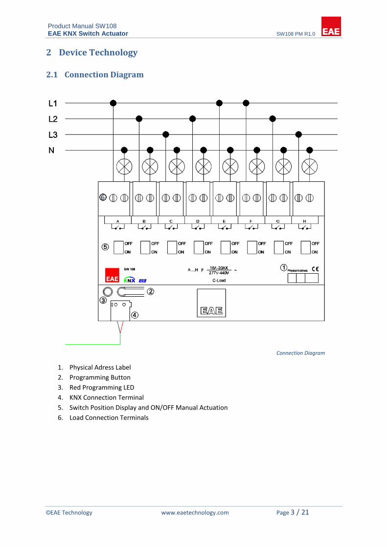
2.1 Connection Diagram
Connection Diagram
1. Physical Adress Label
2. Programming Button
3. Red Programming LED
4. KNX Connection Terminal
5. Switch Position Display and ON/OFF Manual Actuation
6. Load Connection Terminals

Product Manual SW108 EAE KNX Switch Actuator SW108 PM R1.0
©EAE Technology www.eaetechnology.com Page 4 / 21
2.2 Technical Data
Type of protection IP 20 EN 60 529 Safety class II EN 61 140 Power supply : - Voltage 21V… 30V DC, SELV - Current consumption < 10 mA External supply ---
Connections - Screw terminals - Max tightening torque
0,5…4 mm² solid and stranded wire 0,5…2,5mm² stranded wire with ferrule 0.8 Nm
- KNX Bus connect terminal Output - Number 8 output - Switching voltage 277/440V AC; 50/60 Hz - Switching capacity 277 V AC 16A / AC 1 - Fluorescent lighting load to EN 60
669-1 16 AX/250 VAC
Output life - Mechanical life > 3 x 10⁶ Type of contact - potential-free, bistable Installation - 35mm mounting rail EN 60 715 Operating elements - LED (red) and button For physical address Temperature range - Ambient -5° C + 45° C - Storage -25° C + 55° C - Transport -25° C + 70° C Humidity - max. air humidity 95 % no moisture condensation Dimensions 65,5 x 143 x 89mm Weight 0.45 kg Box Plastic, polycarbonate, color grey CE In accordance with the EMC
guideline and low voltage
Application program Communications objects
Number of addresses(max) Number of assignments(max)
122 253 253
NOTE: Device default physical address is 15.15.255. In order to configure universal interface, ETS
application file “.knxprod” is needed. It’s possible to download the file on EAE website. ETS is
required for programming the device. Parameter settings and related group addresses can be
changed by ETS. Learn more read ETS help file.

Product Manual SW108 EAE KNX Switch Actuator SW108 PM R1.0
©EAE Technology www.eaetechnology.com Page 5 / 21
3 Communication Object Table
The following 122 communication objects are available in the SW108. Never are all objects available
together.
No Object name Function DTP Type Number of bits
Flags
0 General, In operation true / false DTP_Bool 1.002 1 bit CWT
1 General Scene 8-bit recall / save DPT_Scene 18.001 1 byte CW
2, 17, 32, 47, 62, 77, 92, 107
Output 1, Switch on / off DPT_Switch 1.001 1 bit CW
3, 18, 33, 48 63, 78, 93, 108
Output 1,Status Switch on / off DPT_Switch 1.001 1 bit CRT
4, 19, 34, 49, 64, 79, 94, 109
Output 1,Enable staircase function
enable / disable DPT_Enable 1.003 1 bit CRW
5, 20, 35, 50, 65, 80, 95, 110
Output 1,Staircase lighting duration
0h … 65535h DPT_TimePeriodHrs 7.007
2 byte CRW
6, 21, 36, 51, 66, 81, 96, 111
Output 1,Permanent ON on / off DPT_Switch 1.001 1 bit CW
7, 22, 37, 52, 67, 82, 97, 112
Output 1,External logic input
on / off DPT_Switch 1.001 1 bit CW
8, 23, 38, 53, 68, 83, 98, 113
Output 1,Forced positioning on / off DPT_Switch_Control 2.001
2 bit CW
9, 24, 39, 54, 69, 84, 99, 114
Output 1,Start value of operating hour
0h … 65535 hour DPT_TimePeriodHrs 7.007
2 byte CW
Output 1,Limit value of operating hour
0h … 65535 hour DPT_TimePeriodHrs 7.007
2 byte CW
10, 25, 40, 55, 70, 85, 100,
115
Output 1,Counter reset of opr. hour
No action/reset trig
DPT_Reset 1.015 1 bit CW
11, 26, 41, 56, 71, 86, 101,
116
Output 1,Current value of opr. hour
0h … 65535h DPT_TimePeriodHrs 7.007
2 byte CR(T)
12, 27, 42, 57, 72, 87, 102,
117
Output 1,Operating hour runout
true / false DPT_Bool 1.002 1 bit CT
13, 28, 43, 58, 73, 88, 103,
118
Output 1,Threshold input Value 0…65535 DPT_Value_2Ucount 7.001
2 byte CW
Output 1,Threshold input Value 0…255 DPT_Value_1Ucount 5.010
1 byte CW
14, 29, 44, 59, 74, 89, 104,
119
Output 1,Threshold value Value 0…65535 DPT_Value_2Ucount 7.001
2 byte CW
Output 1,Threshold value Value 0…255 DPT_Value_1Ucount 5.010
1 byte CW
15, 30, 45, 60, 75, 90, 105,
120
Output 1,Threshold status true / false DTP_Bool 1.002 1 bit CRT
16, 31, 46, 61, 76, 91, 106,
121
Output 1,Sweep trigger DPT_Trigger 1.017 1 bit CW

Product Manual SW108 EAE KNX Switch Actuator SW108 PM R1.0
©EAE Technology www.eaetechnology.com Page 6 / 21
4 Parameters
4.1 Main General
General Parameters
Enable manual Operation *yes no
The switch actuator can be switched on or off with slide switches. This parameter determines the
position of relays can be modified manually or not.
Set the parameter to “yes”.
Each relay can be operated manually.
Set the parameter to “no”.
It is still possible to change relays position but relay return its old position in a maximum of
16 seconds.
Device alive operation active yes *no
This object is used to report that device is still alive and connected the KNX line. Telegram value can
be selected ON/OFF. If a telegram is not received, device may be defective or KNX cable can be
disconnected. If the parameter selected yes;

Product Manual SW108 EAE KNX Switch Actuator SW108 PM R1.0
©EAE Technology www.eaetechnology.com Page 7 / 21
In operation value *send value ‘0’ send value ‘1’
Telegram data can be selected.
Operation send interval [min] 1…*15…255
Here the time interval which in operation communication object cyclically sends to KNX line.
Activate scene yes *no
If the parameter select ‘yes’, scene screen open on the main window. You can find scene information
under the scene function title.
Overwrite threshold value with download *yes no
During storage of a threshold, the threshold values are stored permanently in the device. As an
alternative, the original values can be reloaded into the device during each programming run of the
ETS.
Set the parameter to “yes”
User threshold values store in the device. This means threshold communication object will be
overwrite threshold values but ETS download can’t write on it.
Set the parameter to “no”
Threshold values stored in the device with a storage function will be maintained. If no threshold
values have been stored, the threshold values last programmed in the ETS remain valid.
Overwrite scene values with download *yes no
During storage of a scene, the scene values are stored permanently in the device. As an alternative,
the original values can be reloaded into the device during each programming run of the ETS.
Set the parameter to “yes”
Scenes values stored in the device. This means scene communication object will be overwrite
scene values but ETS download can’t write on it.
Set the parameter to “no”
Scene values stored in the device with a storage function will be maintained. If no scene values
have been stored, the scene values last programmed in the ETS remain valid.
Overwrite operating hour values with download
*yes no
During storage of an operating hour, the operating hour values are stored permanently in the device.
As an alternative, the original values can be reloaded into the device during each programming run of
the ETS.

Product Manual SW108 EAE KNX Switch Actuator SW108 PM R1.0
©EAE Technology www.eaetechnology.com Page 8 / 21
Set the parameter to “yes”
Operating hour values stored in the device. This means operating hour communication object
will be overwrite operating hour values but ETS download can’t write on it.
Set the parameter to “no”
Operating hour values stored in the device with a storage function will be maintained. If no
operating hour values have been stored, the operating hour values last programmed in the ETS
remain valid.
Transmission delay [2…255s] after bus voltage recovery
*2…255
The parameter defines the behavior of the switch actuator at a bus power return. The transmission
delay time determines the period between bus voltage recovery and the point after which telegrams
can be sent.
Telegram limit active yes *no
Parameter selects “yes”;
Telegram limit period 50ms…*10s…1min
The limit period can be adjusted via this parameter.
Max. number of transmitted telegrams within a period
0…20…255
Max number of telegrams per period, can be sent freely.
Product Manual SW108 EAE KNX Switch Actuator SW108 PM R1.0
©EAE Technology www.eaetechnology.com Page 9 / 21
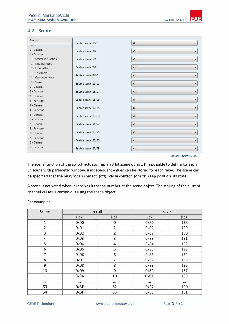
4.2 Scene
Scene Parameters
The scene function of the switch actuator has an 8 bit scene object. It is possible to define for each
64 scene with parameter window. 8 independent values can be stored for each relay. The scene can
be specified that the relay ‘open contact’ (off), ‘close contact’ (on) or ‘keep position’ its state.
A scene is activated when it receives its scene number at the scene object. The storing of the current
channel values is carried out using the scene object.
For example;
Scene recall save
Hex. Des. Hex. Des.
1 0x00 0 0x80 128
2 0x01 1 0x81 129
3 0x02 2 0x82 130
4 0x03 3 0x83 131
5 0x04 4 0x84 132
6 0x05 5 0x85 133
7 0x06 6 0x86 134
8 0x07 7 0x87 135
9 0x08 8 0x88 136
10 0x09 9 0x89 137
11 0x0A 10 0x8A 138
… … … … …
63 0x3E 62 0xE2 190
64 0x3F 63 0xE3 191

Product Manual SW108 EAE KNX Switch Actuator SW108 PM R1.0
©EAE Technology www.eaetechnology.com Page 10 / 21
4.3 Channel General
Channel General Parameters
Contact type normally closed *normally open
The relays of a switching output can be parameterized as normally closed or normally open. This
feature offers the possibility of inversion the switching state. Important: This state is only valid for
switch communication object. Other relay function always works normally.
Normally closed contact
Switch state = off (0) relay contact closed
Switch state = on (1) relay contact open
Normally open contact
Switch state = off (0) relay contact open
Switch state = on (1) relay contact closed
Send switch status feedback telegram no after change after request *after change or request
The switch status feedback can be used as an active or passive communication object. Active
message object, the switch status telegram is transmitted to the bus automatically when a relay state
changes. Passive status object, there is no telegram transmission after relay state changes. If you
want to learn switch status, you must read communication object. Communication object flags are
automatically set by ETS.
NOTE: Switching state changes by manual operation are not detected.

Product Manual SW108 EAE KNX Switch Actuator SW108 PM R1.0
©EAE Technology www.eaetechnology.com Page 11 / 21
Create status object “Status Switch” *yes no
If this parameter select ‘yes’, ETS create another communication object for use only status switch.
The status object can be used to display the current output switching status on a display.
Send status after bus voltage return yes *no
You can use this parameter to send the switching state in the event of bus voltage recovery.
Behavior after ETS program *keep position open contact close contact
After ETS programming, relay position set the wanted switching position.
Set the parameter to “keep position”
In this setting, the relay remains in the current state. Any manual operation occurs in the
meantime the switch actuator return its old position. The device doesn’t know the status of the
relay.
Set the parameter to “open contact” or “close contact”
The relay contact open or close after bus voltage return.
Behavior bus voltage failure *keep position open contact close contact
When the bus voltage fails, the device set the wanted switching state of the output. The relay can be
open, close or keep position it occupied prior to the failure. At the same time, the current switching
position of the relay is stored in the devices.
Behavior bus voltage return keep position open contact close contact *state as before bus voltage failure
When the bus voltage returns, the device set the wanted switching state of the output.
Set the parameter to “keep position”
In this setting, the relay remains in the current state. Any manual operation occurs in the
meantime the switch actuator return its old position. The device doesn’t know the status of the
relay.
Set the parameter to “open contact” or “close contact”
The relay contact open or close after bus voltage return.
Set the parameter to “state as before bus voltage failure”
If the parameter set to “state as before bus voltage failure”, then the relay is set to the value.
The value stored at the time of the bus voltage failure.

Product Manual SW108 EAE KNX Switch Actuator SW108 PM R1.0
©EAE Technology www.eaetechnology.com Page 12 / 21
4.4 Function
Function Parameters
Above function parameters can be set for each channel. These functions;
I. Staircase
II. External logic
III. Internal logic
IV. Priority
V. Threshold
VI. Operating hour
VII. Sweep
Please find description of these functions below.

Product Manual SW108 EAE KNX Switch Actuator SW108 PM R1.0
©EAE Technology www.eaetechnology.com Page 13 / 21
4.4.1 Staircase Function
Staircase Function Parameters
In order to use staircase function, ‘Staircase’ should be enabled on the function window. Than
required parameters and communication objects will be visible. The staircase function can be
parameterized for each channel.
Staircase function has got a three communication object. These are “Enable staircase function”,
“Staircase lighting duration” and “Permanent ON”.
Duration of staircase lighting [min]/ [sec] 0…*5…240[min] *0…59 [sec]
Staircase function on time is calculated by “duration of staircase lighting”. Staircase lighting time is
defined by this parameter. At the end of the on time, the relay off or active the staircase warning
functions.
Staircase retrigger *not retriggerable yes retriggerable up to staircase lighting time 2x up to staircase lighting time 3x up to staircase lighting time 4x up to staircase lighting time 5x
This parameter defines whether the staircase on time can be retrigger able or not so the on time can
be extended by ‘Enable staircase function’. You can repeat retrigger function until the repeater count
reached the maximum value (2x, 3x, 4x, 5x). If the parameter selects ‘not retriggerable’, staircase on
time doesn’t extend.
Reaction to OFF telegram *switch off Ignore
After this parameter selected ‘switching off’, ignored ‘Enable staircase function’ communication
object ‘disable’ command.

Product Manual SW108 EAE KNX Switch Actuator SW108 PM R1.0
©EAE Technology www.eaetechnology.com Page 14 / 21
Staircase time can be changed by object yes *no
‘Staircase lighting duration’ communication object is visible if a ‘Staircase time can be changed by
object’ parameter selects ‘yes’. This communication object is 2 byte. The value defines the staircase
on time in second.
NOTE: After a bus voltage fails, staircase on time returns default value (Duration of staircase lighting).
Restart staircase after “Permanent ON” yes *no
If this parameter is selected ‘yes’, receive ‘Permanent ON’ communication object after restart
staircase function.
Activate pre-warning time? yes *no
The warning function can be activated by this parameter select ‘yes’. Then, you can adjust pre-
warning time, number of pre-warning and time for pre-warning interval. The warning function is for
warning that the staircase lighting time run out and the lights are switched off soon. In the warning,
lights short turn off. Switch status is ON until finish warning time.
Pre-warning time Minutes (0…59) Second (0…59)
*0…59 0…*30…59
How long the lights shall be switched on in the period.
Number of pre-warning (1…10) 1…*2…10
Enter the number of how many blink doing in the warning.
Time for pre-warning intervals Seconds (0…59)
0…*3…59
How long the lights shall be switched off in the period.
Activate on delay yes *no
This parameter is used to delay switch off position before staircase start.

Product Manual SW108 EAE KNX Switch Actuator SW108 PM R1.0
©EAE Technology www.eaetechnology.com Page 15 / 21
4.4.2 External Logic Function
External Logic Parameters
Logic function can be used independently for each output. With this function, the ‘Switch’ object can
be logically linked with the ‘External logic input’. Channel relay switch a result of the logic operation.
For example ‘Switch’ object value 1 and ‘External logic input’ object value 0 relay switch as a result of
1 & 0 operation.
External logic function type *AND OR XOR
This parameter selects the type of logic function between ‘Switch’ and ‘External logic input’ objects.
Invert result yes *no
If you want to inverted logic function result, you should select ‘yes’.
Logic object value after bus voltage return “1” *”0”
This parameter defines the value of the ‘External logic input’ object after bus voltage return.
NOTE: The values of the ‘External logic’ communication objects doesn’t store at the bus voltage
failure.

Product Manual SW108 EAE KNX Switch Actuator SW108 PM R1.0
©EAE Technology www.eaetechnology.com Page 16 / 21
4.4.3 Internal Logic Function
Internal Logic Parameters
You can enter the opening or closing scenario of the channel. In this function, each relay can be
switched only one time because this reaction protects the devices from infinite loop. An internal logic
function can be parameterized separately for each output. The relay of the channel doesn’t
participate to the scenario.
Relay 1…8 state *don’t care off on
To create scenario to open or close channel relay, positions of other channels of the switch actuator
are set with these parameters. The channels that doesn’t need to participate this scenario should be
left don’t care.
4.4.4 Priority Function
If the priority function is enabled, ‘Forced positioning’ communication object is visible. It hasn’t got
any parameter. This is the standard forced position working.
Bit 1 Bit 0 Function
0 0 forced positioning not active – normal control
0 1 forced positioning not active – normal control
1 0 Forced positioning active – switch off
1 1 Forced positioning active – switch on

Product Manual SW108 EAE KNX Switch Actuator SW108 PM R1.0
©EAE Technology www.eaetechnology.com Page 17 / 21
4.4.5 Threshold Function
Threshold Parameters
The function can be configured 1 byte or 2 byte. The value of Threshold input communication object
falls below or exceeds a limit of threshold value. Then the relay position can be changed by this way.
Object size *1 byte 2 byte
The threshold value function data type determined here. All of the parameters associated with it
which will change.
Threshold value 0…*128…255 (for 1 byte) 0…*20000…65535 (for 2 byte)
Threshold limit value enters here. This parameter is dependent ‘Object size’ parameter.
Threshold reaction *OFF (0) below threshold, ON (1) above threshold ON (1) below threshold, OFF (0) above threshold
This parameter determines the switch state. If the value of the ‘Threshold input’ communication
object value bellows or above the threshold limit value, the relay switched on or off position.
Threshold value can be changed by object
yes *no
If the parameter selects ‘yes’, ‘Threshold value’ communication object is visible. Threshold value can
be changed by this object.
Threshold hysteresis yes *no
Hysteresis is dependence of a system not only its current value but also on its past value.
If the parameter selects ‘yes’;

Product Manual SW108 EAE KNX Switch Actuator SW108 PM R1.0
©EAE Technology www.eaetechnology.com Page 18 / 21
Hysteresis percentage (1…10) %1…*%5…%11
For example: Hysteresis percentage parameter selected %10. You can see this state below graphic.
Threshold hysteresis value measure formula 100 * 10 / 100 = 10 and threshold high and low limit 100
+- 10.
Threshold Graphic

Product Manual SW108 EAE KNX Switch Actuator SW108 PM R1.0
©EAE Technology www.eaetechnology.com Page 19 / 21
4.4.6 Operating Hour Function
Operating Hour Parameters
The operating hours count the relay on time. The operating hours sums up to determined on time.
The accumulated operating hours are stored in the 2 byte counter. The counter value sends to bus
cyclically or after request. If the voltage fails or ETS programming, all operating hour counter stored
in the devices. After the bus voltage returns, the device updates communication object value.
NOTE: User changed relay position by hand; device cannot detect it so operating hour doesn’t start
the counting.
Counter type *up counter down counter
Up counter: The operating hours start the count from ’0’. The maximum counting value is 65535
hours. When the operating hour reached limit value, ‘Operating hour runout’ telegram sends to bus.
Then the operating hours counter stop.
Down counter: The operating hours preset value counting down. When the counter reached ‘0’, the
counting status is reported to the bus via ‘Operating hour runout’.
Limit value preset no preset *set with parameter set with object
The start or limit value preset here. A limit value can be preset as an option.
No preset
For up/down counter the limit value set to 65535. This is the maximum value both of operating
hour.

Product Manual SW108 EAE KNX Switch Actuator SW108 PM R1.0
©EAE Technology www.eaetechnology.com Page 20 / 21
Set with parameter
This parameter selects; ‘Limit value/Counter start’ parameter is visible. This parameter is used for
setting limit value of up counter, start value of down counter.
Set with object
This parameter defines whether the start/limit value can be individually adapted from the bus.
Send counter value cyclic sending *after request cyclic sending and after request
The current count of the operating hours can be learned three way ‘cyclic sending’, ‘after request’
and ‘cyclic sending and after request’.
4.4.7 Sweep Function
Sweep Parameters
Sweep function only starts to operate if the relay is switched ON. It’s an alternative way for turning
off the relay with pre-warning. The sweep function is desired to warn a person that lights will go out
shortly.
Send counter value 1…*3…10
The lamps connected to the relay will then be switched off as many times. Enter the number of how
many blink doing in the warning.
Blink on time 0,5sec…*1sec…5sec
How long the lights shall be switched on in the period.

Product Manual SW108 EAE KNX Switch Actuator SW108 PM R1.0
©EAE Technology www.eaetechnology.com Page 21 / 21
Blink off time *300ms…1sec
How long the lights shall be switched off in the period.
Wait time after blinks (sec) 0…*30…255
How long the lights shall be switched on after sweep blink finished.
5 Process Priority Table