e-chains for the prevention of static and ignitable charge
DESCRIPTION
This cataloque includes - the range of electricaly conductive energy chains available within the igus product range. It also includes technical data and application techniques.TRANSCRIPT

®
e.chains.
esd.atex.®.eu...e-chainsystem
s®...P
roduct range...24h, from stock... 01.01.2012
D-EU-ESD KATALOG ICON 23.11.2011 15:08 Uhr Seite 1

2
In more and more applications in modern production facilities, the demands on the prevention of sta-tic charges are increasing. Essentially there are two reasons for this
● ESD - Avoidance of static charges in the field of manufacturing processes of electronic components or assemblies
● ATEX - Prevention of explosive static charge in hazardous environment
Measurements of the electrical surface leakage resistance for igus® e-chains® with the special material igumidGC were made already in 1992 by the igus® GmbH together with the PTB (Physikalisch-Technische-Bundes-anstalt) in Braunschweig, supplemented by additional certifications in 1998 and 1999 according to DIN 53482and the guidelines for static electricity "ZH1/200" of the Federation of Trade Associations. In the course of fur-ther innovation, the material igumid ESD was certified by the PTB (Physikalisch-Technische-Bundesanstalt) inMay 2002. The material igumid ESD combines in its properties the requirements of the ESD as well as ATEXcriteria. In some mechanical requirements, the igumid ESD surpasses even the standard material igumid GLWand has been tested with over 10 million cycles in the igus® technology center.
Your benefits with ESD products● ESD material tested with over 10 million cycles for the highest requirements● Snap-open e-chains® with mounting brackets and interior separation
in ESD and ATEX design available from stock● Standardized product - igumid ESD with PTB certificate● Proven over years of use in explosion-proof areas● Short delivery times: 7.00 - 20.00 h - ordering and delivery service
ESD&ATEX...ig
More information at: [email protected] or http://atex-info.igus.eu
Available from stock. Delivery in 24h or today!* *Delivery time means time until shipping of goods
D-EU-ESD KATALOG ICON 23.11.2011 15:08 Uhr Seite 2

3
Conductivity ofigus® productsfrom igumid ESDIn contrast to temporarily acting applied conduc-tive surface coatings or volatile incorporated anti-static agents, the used additives grant a long lastingand maintenance-free conductivity. An e-chain® isnot sufficient to ensure sufficient conductivity, if onlythe individual components exhibit conductivity, butthe whole e-chain® from one to the other end musthave a continuous conductivity. All products in thiscatalog are optimized in this regard and the conti-nuous conductivity is measured and documentedprior to delivery by a 100% test.Only e-chains® that have passed this test are provi-ded with the test seal and delivered. Color* of igu-mid ESD products: similar to RAL7015, slate-grayto secure distinguishability with standard materials.(*Exception: Cover zipper e-chains® series 07/09 - here black in color)
us®...e-chains®...
100% of the produced
ESD e-chains® are checked
for their continuous conductivity
"from one end to the other"
igus® GmbH 51147 Cologne | Phone +49- (0) 22 03-96 49-800 Fax -222 | [email protected] | www.igus.eu
D-EU-ESD KATALOG ICON 23.11.2011 15:08 Uhr Seite 3

4
igumid...ESD...Structural designNot only the material is important for a safe electrostatic discharge. The structural design is also crucial for atruly safe use. The e-chains® from the E4.1 modular kit ensure a permanently constant discharge because theyhave a positive connection of the chain links to one another. With the patented "tongue and groove", the innerplate engages the outer plate - thereby guaranteeing a discharge - even after several million cycles. The e-chains® from the E2/000 range ensure a safe discharge as the clearance between the pins and the bore of thelinks to each other is extremely low. Installation instructions with respect to ESD/Atex and declaration ofconformity can be found on page 68/69 of this catalog.
Nothing suitable in the bearing range? Many other products of the complete igus® e-chains® range are also available as special design in ESD/Atexversions. igus® will be happy to make an offer for your individually desired product in the required quanti-ty, if technically possible. The significantly improved profitability, as well as the rapid availability of the bea-ring range - especially in the spare parts supply - should always constitute the first choice.
A little tip from the igus® plain bearings world: A huge range of conductive iglidur®
plastic plain bearings available from stock can be found at www.igus.eu/eu/F
igumid ESD materials data
*Valuees upon request
Important notice: Using the special material in combination with reduced pin/bore clearance can lead to a higher rolling resistance compared to e-chain®
in standard version - especially when using the e-chain® in countries with persistently high levels of humidity.
Materials data Measurement Values
igumid ESD units igumid ESD
Mechanical properties
Yield stress (dry/wet) MPa *
Elongation at break (dry/wet) % *
Modulus of elasticity (tensile test) MPa *
Elasticity limit (bending) MPa 9.500
Bending strength MPa 230
Shore hardness D – 83
General properties
Density g/m3 1,2
Moisture absorption 23/50 RF Wt.-% 1,9
Maximum water absorption Wt.-% 7,3
Electrical properties
Specific contact resistance Ω*cm <109
Surface resistance ROA Ω <109
Materials data Measurement Values
igumid ESD units igumid ESD
Thermal properties
Lower operating temperature °C -40°C / -40°F
Upper long-term operating temperature°C 80°C / 176°F
Upper short-term operating temperature°C 150°C / 302°F
Material evidence
Fire behavior according to UL94 – HB
Silicon-free – Yes
Halogen-free – Yes
2002/95/EG (RoHS) – Yes
2002/96/EG (WEEE). – Yes
Color (RAL, approximately)
ESD e-chains® slate-gray ≈ RAL7015
Exception: Lid zipper Series 07/09 black ≈ RAL9004
D-EU-ESD KATALOG ICON 23.11.2011 15:08 Uhr Seite 4

5
Applications
ESD application with igus® E2/000 e-chains® of the series 2400 in a centrifuge
for de-oiling, drying, cleaning, coating and rust protection
igus® ESD option of the system E2/000 in a tank car filling station.
100% ATEX safety must be ensured during the transport of gases.
D-EU-ESD KATALOG ICON 23.11.2011 15:08 Uhr Seite 5

ø 8ø 13
ø 18ø 23ø 32
ø 18ø 25ø 28ø 38ø 50ø 74
ø 56ø 74
10,315
212535
212832425680
6280
07 10 - 50 1509 16 - 50 19,3
1500 15 - 80 282500 25 - 125 352700 50 - 125 50
E4.21 30 - 70 28E4.28 40 - 125 42E4.32 50 - 200 54E4.42 50 - 200 64E4.56 75 - 300 84E4.80 75 - 300 108
14240 50 - 200 8415050 75 - 300 108
hi ø max.
Bi
ha
6Available from stock. Delivery in 24h or today!* *Delivery time means time until shipping of goods
Inner widthBi [mm]from - to
Series /product
Inner heighthi [mm] +ø cable max.
Outer heightha [mm]
Openingprinciple
ESD&ATEX.....zipper e-chains® - quick opening due to zipper-principleESD e-chains® - zip-open along outer radius
ESD e-chains® - snap-open along outer radius
ESD e-chains® - crossbars every link - robust version- can be opened from both sides
ESD e-chains® - crossbars every link - light version - can be opened from both sides
Legende● Standard� Suitable to a limited extent▲ Options■ Especially suitable* In preparation/upon request
E2/000 e-chains® - two-piece e-chains® - the E2 standard!
E4.1 - ONE e-chain® family for all applications
E4/light - specialty: light weight - low price, cost effective
D-EU-ESD KATALOG ICON 23.11.2011 15:08 Uhr Seite 6

16,5- 57 18 - 38 20 0,4 0,55 – – – 1024,2- 58,2 28 - 48 20 0,7 1,0 – ● ● 14
28,5- 93,5 38 - 145 33,3 2 1,75 75 ● ● 2041 - 141 55 - 175 46 5 2,25 100 ● ● 2466 - 141 63 - 150 56 8 2,75 120 ● ● 28
44 - 84 48 - 100 30,5 4 2,5 120 ● ● 3460 - 145 55 - 125 46 10 2,5 200 ● ● 3873 - 223 63 - 250 56 15 3,3 200 ● – 4276 - 226 75 - 250 67 37 4,0 300 ● – 46109 - 334 135 - 250 91 62,5 5,0 400 ● – 50100 - 350 200 - 300 111 80 6,2 400 ● – 54
76 - 226 150 - 250 91 40 4,0 150 ● – 60105 - 330 150 - 250 91 55 4,6 250 ● – 64
R
m
kg
mBa
7igus® GmbH 51147 Cologne | Phone +49- (0) 22 03-96 49-800 Fax -222 | [email protected] | www.igus.eu
Sepa
rato
rs
Full w
idth
She
lves
Interior separationpossiblities
PageOuter widthBa [mm]from - to
Bending radiusR [mm]von - bis
Pitch [mm]
Unsupportedfill weightmax [kg/m]
Unsupportedlength FLBmax [m]
Long travelmax [m]
Product range..
D-EU-ESD KATALOG ICON 23.11.2011 15:08 Uhr Seite 7

8
Zipper
Available from stock. Delivery in 24h or today!* *Delivery time means time until shipping of goods
zipper ESD Introduction
zipper ESD - zip fastening e-chains®
zipper e-chains® convince in practicality andperformance. The "zipper" function makesthem a very useful product to reduce assem-bly time. The small pitch, the tough-elasticzipper-band, and the sturdy link work well inhigh-acceleration environments. The "zipper"Series is one of the most popular e-chain®
Series in demanding applications.● zipper-like design for quick
opening and closing of lids● zipper lids can be separated
and joined at each chain link● Small pitch for low noise and
smooth operation● High accelerations: 100 m/s2
and more are possible● Interior separation possible for
larger versions (Series 09)
Typical industries and applications● Pick & place robots ● Semi-conductor machines ● Linear motors, actuators ● Measuring equipment● Machine tools
Fast Opening and Closing
with "zipper"
iF-Design
Award Winner
D-EU-ESD KATALOG ICON 23.11.2011 15:08 Uhr Seite 8

hi [mm] Bi [mm] Ba [mm] ha [mm] R [mm]
07 10,3 10 - 50 16,5 - 57 15,0 18 - 38 0,55 1009 15,0 16 - 50 24,2 - 58,2 19,3 28 - 48 1,00 14
9
07 ≤ 0,55 m
09 ≤ 1,0 m
FLG
FLB
Technical Data - zipper ESD
Vertical hanging
Vertical standing
Side mounted unsupported
Unsupported application
e-chain®
Series
Installation methods overview, maximum travels - zipper ESD
FLG = with straight upper run FLB = with permitted sag
Gliding speed / acceleration (maximum) max. 10 [m/s] / max. 50 [m/s2]
Speed / acceleration FLG max. max. 20 [m/s] / max. 200 [m/s2]
Speed / acceleration FLB max. max. 3 [m/s] / max. 6 [m/s2]
Material - permitted temperature °C igumid ESD / -40° up to +80° C
Flammability class, igumid ESD VDE 0304 IIC UL94 HB
upon request upon request upon request
upon request upon request upon request
igus® GmbH 51147 Cologne | Phone +49- (0) 22 03-96 49-800 Fax -222 | [email protected] | www.igus.eu
zipper ESD Contents Technical Data
Series Inner height Inner width Outer width Outer height Bending radius Unsupported Page
length max. [m]
zipper - two-piece ESD e-chains®
zip-open along outer radius
9
D-EU-ESD KATALOG ICON 23.11.2011 15:08 Uhr Seite 9

1010
07.
07.
07.
07.
07.
07.
10
16
20
30
40
50
.R.0.ESD
.R.0.ESD
.R.0.ESD
.R.0.ESD
.R.0.ESD
.R.0.ESD
BaBi
8,0max. 10
,3
15
Ba[mm]
Bi[mm]
16,5
22,5
27
37
47
57
10
16
20
30
40
50
| 018 | 028 | 038 |
| 018 | 028 | 038 |
| 018 | 028 | 038 |
| 018 | 028 | 038 |
| 018 | 028 | 038 |
| 018 | 028 | 038 |
07. 40. 038.0.ESD
07ESD 10,3
060.10. 12PZ.ESD
060.16. 12PZ.ESD
060.20. 12PZ.ESD
060.30. 12PZ.ESD
060.40. 12PZ.ESD
060.50. 12PZ.ESD
Index: ESD, color grey
Bending radius R
Width index (depends on Bi)
Series / Type
Order key
R Bending radii[mm]
Available from stock. Delivery in 24h or today!* *Delivery time means time until shipping of goods
zipper ESD Series 07 Product range
zipper ESD | Series 07 | zip-open along outer radius
3D-CAD files, configurators, PDF www.igus.eu/eu/07
Supplement Part No. with required radius (R) Example: 07.40.038.0.ESD
ESD e-chains®
from stock* ESD Mounting brackets Polymer, one-piece from stock*
D-EU-ESD KATALOG ICON 23.11.2011 15:08 Uhr Seite 10

0.25
00.25 1.000 0.75
0.50
0.75
1.00
0.50 1.00 2.000 1.50
FLBFLG
0.50
S/2
20
S
H -
15
15
H
D
HF
= H
+ 1
0
22R+3
FLG
FLB
H
HF
S (FLG)
S (FLB)
R 018 028 038
H 51 71 91
D 56 66 76
K 100 130 160
11
07ESD
FLG = with straight upper runFLB = with permitted sag
S = Length of travelR = Bending radius
H = Nominal clearance heightHF = Required clearance height
D = Overlength e-chain®, radius in final positionK = π • R + "safety"
Moving end
Fixed end
Fill
wei
ght
[kg
/m]
Unsupported length FLG / FLB [m]
Length of travel S [m]
Example
Fill weight = 0,25 [kg/m]
Unsupported length FLB = 0,52 m
Length of travel = 1,04 m
The required clearance height: HF = H + 10 mm (with 0,2 kg/m fill weight)
Unsupported e-chains® feature positive
camber over short travels. This must be
accounted for when specifying the clea-
rance height HF. Please consult igus® if
space is particularly restricted.
The diagrams for unsupported length are appli-cable for the standard e-chains® in the igumid GLWmaterial. The values can also be used for the asses-sment of e-chain® applications in special materialESD. If the respective maximum unsupported lengthexceeds 80%, the suitability of the e-chain® shouldbe verified by a practice-oriented test.
Unsupported applications
igus® GmbH 51147 Cologne | Phone +49- (0) 22 03-96 49-800 Fax -222 | [email protected] | www.igus.eu
zipper ESD Series 07 Dimensions Unsupported
Pitch = 20 mm/link Links/m = 50 (1000 mm)Chain length= S/2 + K
Speed, material, temperature and
flammability class page 9
Technical Data
D-EU-ESD KATALOG ICON 23.11.2011 15:08 Uhr Seite 11

060.40.1PZA1.ESD
060.40.2PZA1.ESD
12
A1 A3A2 A4
10.
16.
20.
30.
40.
50.
060.10. 12PZ.ESD
060.16. 12PZ.ESD
060.20. 12PZ.ESD
060.30. 12PZ.ESD
060.40. 12PZ.ESD
060.50. 12PZ.ESD
060.40.12PZA1.ESD
–
–
–
22
32
42
16,5
22,5
27,0
37,0
47,0
57,0
1
2
2
3
4
5
07ESD
5,8/90° 5,8/90°
B
10 8 41084
3,2 3,2
A A B
17
90°
060...1(PZ) 060...2(PZ)
Part No. structure
Number
of teeth
A…must be indicated onpreassembled configurations
Full set = 12
Mounting brackets forselected width index
Width
Index
Dim. A[mm]
Dim. B[mm]
Part No. ESD
full set with
tiewrap plates
Index: ESD
3D-CAD files, configurators, PDF www.igus.eu/eu/07
With integrated strainrelief tiewrap plates
Possible installation conditions: For the preassembled mode please add index A1... A4 e.g. 060.40.12PZ.A1.ESD
Single-part order
Mounting bracket Moving end
(preass. + tiewrap plate)
Mounting bracket Fixed end
(preass. + tiewrap plate)
One-piece mounting bracket
Available with or without
strain relief tiewrap plates
Corrosion-resistant
Inner and outer attachment possible
Various installation options on the
fixed end and/or the moving end
ESD mounting bracket | Polymer locking, one-pieceRecommended for unsupported and gliding applications
zipper ESD Series 07 Mounting bracketsOne-piece mounting bracket
Moving end
Fixed end
Moving end Fixed end
060.16.12 - 060.20.12: center bores only
060.30.12 - 060.40.12: bores (see figure above)
D-EU-ESD KATALOG ICON 23.11.2011 15:08 Uhr Seite 12

13
07ESD
igus® GmbH 51147 Cologne | Phone +49- (0) 22 03-96 49-800 Fax -222 | [email protected] | www.igus.eu
zipper ESD Series 07 My Sketches
D-EU-ESD KATALOG ICON 23.11.2011 15:08 Uhr Seite 13

1414
09.
09.
09.
09.
09.
16
20
30
40
50
.R.0.ESD
.R.0.ESD
.R.0.ESD
.R.0.ESD
.R.0.ESD
BaBi
12,5max. 15 19
,3
Ba[mm]
Bi[mm]
24,2
28,2
38,2
48,2
58,2
16
20
30
40
50
| – | 038 | – |
| – | – | 048 |
| 028 | 038 | 048 |
| 028 | 038 | 048 |
| 028 | 038 | 048 |
09. 40. 048.0.ESD
09ESD 15
1,4
7
B09.2.ESD
B09.2.1.ESD
080.16. 12PZ.ESD
080.20. 12PZ.ESD
080.30. 12PZ.ESD
080.40. 12PZ.ESD
080.50. 12PZ.ESD
Order key
Index: ESD, color grey
Bending radius R
Width index (depends on Bi)
Series / Type
R Bending radii[mm]
Available from stock. Delivery in 24h or today!* *Delivery time means time until shipping of goods
zipper ESD Series 09 Product range
zipper ESD | Series 09 | zip-open along outer radius
zipper ESD | Series 09 | Interior separation | Standard
3D-CAD files, configurators, PDF www.igus.eu/eu/09
Supplement Part No. with required radius (R) Example: 09.40.048.0.ESD
ESD e-chains®
from stock*
Standard separator ESDFor all applications. Maximum locking strength
and safe standing in e-chains®. In the standard
configuration separators are assembled every 2nd
e-chain® link! More interior separators upon request.
ESD Mounting brackets Polymer, one-piece from stock*
Slotted separator
ESD
unassembled
assembled
D-EU-ESD KATALOG ICON 23.11.2011 15:08 Uhr Seite 14

0.25
00.25 0.50 1.000 0.75
0.50
0.75
1.00
0.50 1.00 2.000 1.50
FLB
FLG
S/2
20
S
H -
19,
3
19,3
H
D
HF
= H
+ 1
5
28R+3
FLG
FLB
H
HF
S (FLG)
S (FLB)
R 028 038 048
H 75 95 115
D 68 78 88
K 130 160 195
15
09ESD
Moving end
Fixed end
Fill
wei
ght
[kg
/m]
Unsupported length FLG / FLB [m]
Length of travel S [m]
Example
Fill weight = 0,5 [kg/m]
Unsupported length FLB = 0,63 m
Length of travel = 1,26 m
The required clearance height: HF = H + 15 mm (with 0,3 kg/m fill weight)
igus® GmbH 51147 Cologne | Phone +49- (0) 22 03-96 49-800 Fax -222 | [email protected] | www.igus.eu
zipper ESD Series 09 Dimensions Unsupported
Pitch = 20 mm/link Links/m = 50 (1000 mm)Chain length= S/2 + K
Speed, material, temperature and
flammability class page 9
Technical Data
Unsupported e-chains® feature positive
camber over short travels. This must be
accounted for when specifying the clea-
rance height HF. Please consult igus® if
space is particularly restricted.
The diagrams for unsupported length are appli-cable for the standard e-chains® in the igumid GLWmaterial. The values can also be used for the asses-sment of e-chain® applications in special materialESD. If the respective maximum unsupported lengthexceeds 80%, the suitability of the e-chain® shouldbe verified by a practice-oriented test.
Unsupported applications
FLG = with straight upper runFLB = with permitted sag
S = Length of travelR = Bending radius
H = Nominal clearance heightHF = Required clearance height
D = Overlength e-chain®, radius in final positionK = π • R + "safety"
D-EU-ESD KATALOG ICON 23.11.2011 15:08 Uhr Seite 15

080.40.1PZA1.ESD
080.40.2PZA1.ESD
16
A1 A3A2 A4
16
20
30
40
50
080.16. 12PZ.ESD
080.20. 12PZ.ESD
080.30. 12PZ.ESD
080.40. 12PZ.ESD
080.50. 12PZ.ESD
080.40.12PZA1.ESD
–
–
22
32
42
24,2
28,2
38,2
48,2
58,2
2
2
3
4
5
09ESD
B
15 8 51585
A BA
5,8/90° 5,8/90°
3,2 3,2
17
3°
2°
3°
080...1(PZ) 080...2(PZ)
Single-part order
Mounting bracket Moving end
(preass. + tiewrap plate)
Mounting bracket Fixed end
(preass. + tiewrap plate)
Number
of teeth
3D-CAD files, configurators, PDF www.igus.eu/eu/09
With integrated strainrelief tiewrap plates
A…must be indicated onpreassembled configurations
Full set = 12
Mounting brackets forselected width index
Part No. structure
Width
Index
Dim. A[mm]
Dim. B[mm]
Part No. ESD
full set with
tiewrap plates
Possible installation conditions: For the preassembled mode please add index A1... A4 e.g. 080.40.12PZA1.ESD
One-piece mounting bracket
Available with or without
strain relief tiewrap plates
Corrosion-resistant
Inner and outer attachment possible
Various installation options on the
fixed end and/or the moving end
ESD mounting bracket | Polymer locking, one-pieceRecommended for unsupported and gliding applications
zipper ESD Series 09 Mounting bracketsOne-piece mounting bracket
Index: ESD
Moving end
Fixed end
Moving end Fixed end
080.16.12 - 080.20.12: center bores only
080.30.12 - 080.40.12: bores (see figure above)
D-EU-ESD KATALOG ICON 23.11.2011 15:08 Uhr Seite 16

17
09ESD
igus® GmbH 51147 Cologne | Phone +49- (0) 22 03-96 49-800 Fax -222 | [email protected] | www.igus.eu
zipper ESD Series 09 My Sketches
D-EU-ESD KATALOG ICON 23.11.2011 15:08 Uhr Seite 17

18Available from stock. Delivery in 24h or today!* *Delivery time means time until shipping of goods
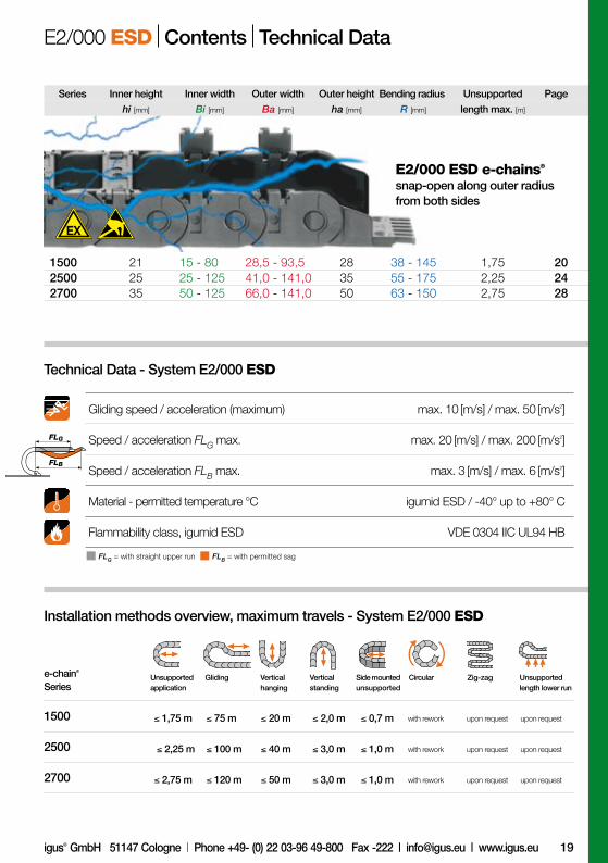
E2/000 ESD Introduction
E2/000 ESD with 2-piecelink-design for a wide range of applicationsDie E2/000 Series is igus® fourth generationin this popular size range. All past experienceswent into this Millenium Series: easy and ver-satile assembly combined with ruggedness- high stability paired with quieter motion -long cable life and many fixation options. Thedesign is consistent within all E2/000 varia-tions. It is the standard product for machinebuilders around the world.
Typical industries and applications● Pick & place robots ● Semi-conductor machines ● Linear motors, actuators ● Measuring equipment● Machine tools
System E2/000 -
2-piece link-design
Electrically conductive ESD/ATEX version
with PTB-certification upon request
D-EU-ESD KATALOG ICON 23.11.2011 15:08 Uhr Seite 18
hi [mm] Bi [mm] Ba [mm] ha [mm] R [mm]
1500 21 15 - 80 28,5 - 93,5 28 38 - 145 1,75 202500 25 25 - 125 41,0 - 141,0 35 55 - 175 2,25 242700 35 50 - 125 66,0 - 141,0 50 63 - 150 2,75 28
19
1500 ≤ 1,75 m ≤ 75 m ≤ 20 m ≤ 2,0 m ≤ 0,7 m
2500 ≤ 2,25 m ≤ 100 m ≤ 40 m ≤ 3,0 m ≤ 1,0 m
2700 ≤ 2,75 m ≤ 120 m ≤ 50 m ≤ 3,0 m ≤ 1,0 m
FLG
FLB
e-chain®
Series
with rework upon request upon request
with rework upon request upon request
with rework upon request upon request
Vertical hanging
Vertical standing
Side mounted unsupported
Unsupported application
Gliding Zig-zag Circular Unsupportedlength lower run
Installation methods overview, maximum travels - System E2/000 ESD
Gliding speed / acceleration (maximum) max. 10 [m/s] / max. 50 [m/s2]
Speed / acceleration FLG max. max. 20 [m/s] / max. 200 [m/s2]
Speed / acceleration FLB max. max. 3 [m/s] / max. 6 [m/s2]
Material - permitted temperature °C igumid ESD / -40° up to +80° C
Flammability class, igumid ESD VDE 0304 IIC UL94 HB
FLG = with straight upper run FLB = with permitted sag
Technical Data - System E2/000 ESD
igus® GmbH 51147 Cologne | Phone +49- (0) 22 03-96 49-800 Fax -222 | [email protected] | www.igus.eu
E2/000 ESD Contents Technical Data
Series Inner height Inner width Outer width Outer height Bending radius Unsupported Page
length max. [m]
E2/000 ESD e-chains®
snap-open along outer radiusfrom both sides
D-EU-ESD KATALOG ICON 23.11.2011 15:08 Uhr Seite 19

20
21 21
20
1500.
1500.
1500.
1500.
1500.
1500.
015
025
038
050
068
080
.R.0.ESD
.R.0.ESD
.R.0.ESD
.R.0.ESD
.R.0.ESD
.R.0.ESD
BaBi
18max. 21 28
Ba[mm]
Bi[mm]
28,5
38,5
51,5
63,5
81,5
93,5
15
25
38
50
68
80
| 038 | 048 | – | – | – | – |
| 038 | 048 | 075 | – | – | – |
| 038 | 048 | 075 | – | – | – |
| 038 | 048 | 075 | 100 | 125 | – |
| 038 | 048 | 075 | 100 | 125 | 145 |
| 038 | 048 | 075 | 100 | 125 | 145 |
1500. 038. 038.0.ESD
1500ESD 21
2,5
10
21.1
21.1.ESD
21.1.1.ESD
–
15000.025.34PZB.ESD
15000.038.34PZB.ESD
15000.050.34PZB.ESD
15000.068.34PZB.ESD
15000.080.34PZB.ESD
Index: ESD, color grey
Bending radius R
Width index (depends on Bi)
Series / Type
Order key
R Bending radii[mm]
Available from stock. Delivery in 24h or today!* *Delivery time means time until shipping of goods
E2/000 ESD Series 1500 Product range
ESD e-chains® | Series 1500 | snap-open along outer radius
ESD e-chains® | Series 1500 | Interior separation | Standard
3D-CAD files, configurators, PDF www.igus.eu/eu/1500
Supplement Part No. with required radius (R) Example: 1500.038.038.0.ESD
ESD e-chains®
from stock*
Standard separator ESDFor all applications. Maximum locking strength
and safe standing in e-chains®. In the standard
configuration separators are assembled every 2nd
e-chain® link! More interior separators upon request.
KMA mounting brackets ESDpivoting, from stock**
Slotted separator
ESD
unassembled
assembled
D-EU-ESD KATALOG ICON 23.11.2011 15:08 Uhr Seite 20

8.0
20
10
6.0
4.0
2.0
1.5
1.0
0.5
00.5 1.0 2.0 3.01.5 2.50 3.5
0 2.0 4.0 6.0
FLG
FLB
D
H
H -
28
R33,3
S/2
S
28
HF
= H
+ 2
5
32
37,5
FLG
FLB
H
HF
S (FLG)
S (FLB)
R 038 048 075 100 125 145
H 104 124 178 228 278 318
D 102 112 139 164 189 209
K 190 220 305 385 460 525
21
1500ESD
Moving end
Fixed end
Fill
wei
ght
[kg
/m]
Unsupported length FLG / FLB [m]
Length of travel S [m]
Example
Fill weight = 1,5 [kg/m]
Unsupported length FLB = 1,3 m
Length of travel = 2,6 m
The required clearance height: HF = H + 25 mm (with 0,5 kg/m fill weight)
igus® GmbH 51147 Cologne | Phone +49- (0) 22 03-96 49-800 Fax -222 | [email protected] | www.igus.eu
E2/000 ESD Series 1500 Dimensions Unsupported
Pitch = 33,3 mm/link Links/m = 30 (1000 mm)kettenlänge = S/2 + K
Speed, material, temperature and
flammability class page 19
Technical Data
Unsupported e-chains® feature positive
camber over short travels. This must be
accounted for when specifying the clea-
rance height HF. Please consult igus® if
space is particularly restricted.
The diagrams for unsupported length are appli-cable for the standard e-chains® in the igumid GLWmaterial. The values can also be used for the asses-sment of e-chain® applications in special materialESD. If the respective maximum unsupported lengthexceeds 80%, the suitability of the e-chain® shouldbe verified by a practice-oriented test.
Unsupported applications
FLG = with straight upper runFLB = with permitted sag
S = Length of travelR = Bending radius
H = Nominal clearance heightHF = Required clearance height
D = Overlength e-chain®, radius in final positionK = π • R + "safety"
D-EU-ESD KATALOG ICON 23.11.2011 15:08 Uhr Seite 21

22
A1 A3A2 A4
ø 5,5
A B
ø 6,2
12
20
B A
ø 6,2
12 32
ø 5,5
37,5 37,5
.015.
.025.
.038.
.050.
.068.
.080.
–
15000.025.34PZB.ESD
15000.038.34PZB.ESD
15000.050.34PZB.ESD
15000.068.34PZB.ESD
15000.080.34PZB.ESD
15000.038.4PZA1.ESD
15000.038.3PZA1.ESD
15000.038.34PZA1.ESD
15000...3PZ(B) 15000...4PZ(B)
–
12
25
37
55
67
–
15
20
30
40
60
–
3
4
5
6
8
1500ESD
Number
of teeth
3D-CAD files, configurators, PDF www.igus.eu/eu/1500
With integrated strainrelief tiewrap plates
A…must be indicated onpreassembled configurations
Full set = 34
Mounting brackets forselected width index
Part No. structure
Width
Index
Dim. A[mm]
Dim. B[mm]
Part No. ESD
full set with
tiewrap plates
Possible installation conditions: For the preassembled mode please add index A1... A4 e.g. 15000.038.34PZBA1.ESD
Single-part order
Mounting bracket Moving end
(preass. + tiewrap plate)
Mounting bracket Fixed end
(preass. + tiewrap plate)
For tight installation conditions
Strain relief with detachable
tiewrap plates
Variable traverse angle
for flexible assembly
Corrosion-resistant
Various installation options on the
fixed end and/or the moving end
Note: Mounting brackets not to assemble at the gable end
ESD mounting bracket | Polymer pivotingRecommended for unsupported and gliding applications
Moving end
Fixed end
Moving end Fixed end
10-57° je nach Radius
E2/000 ESD 1500 KMA Mounting brackets pivotingFor tight installation conditions
Index: ESD
D-EU-ESD KATALOG ICON 23.11.2011 15:08 Uhr Seite 22

23
37
37
ø 4,5A =
Bi -
7
A =
Bi -
7
1537
537
ø 4,5 ø 4,5
B =
Bi +
24
C =
Bi +
27ø 4,5
15 5
.015.
.025.
.038.
.050.
.068.
.080.
39
49
62
74
92
104
14000.12
14000.12
14000.12
14000.12
14000.12
14000.12
14000. 1
14000. 2
14000. 12.E
14000.1 14000.2* 14000.1 14000.2*
8
18
31
43
61
73
14000.12.E
14000.12.E
14000.12.E
14000.12.E
14000.12.E
14000.12.E
42
52
65
77
95
107
1500ESD
Full set, 4 parts2 with pin / 2 with bore
Mounting bracket
Optional stainless steel
Part No. structure
Possible installation conditions - further installation angles installation sketch
Note: By ordering steel mounting brackets in combination
with an e-chain®, they will be delivered assembled!
Width
Index
Dim. B[mm]
Dim. C[mm]
Dim. A[mm]
Part No.
full set
Part No.
full set
stainless steel**
Single-part order
Mounting bracket Moving end
(1 part left / right)
Mounting bracket Fixed end
(1 part left / right)
Locked connections
One part (2-piece) for
all e-chain® widths
Electrically conductive
Bolted connection outside of
chain cross-section possible
Stainless steel version available(**Material: stainless steel 1.4301)
*pivoting with no stop (360°). Screw-on area of the mounting brackets can be on the interior or exterior.
Mounting bracket | Steel lockingRecommended for unsupported, vertical hanging and standing applications
Moving end
Fixed end
Moving end Fixed end Moving end Fixed end
E2/000 ESD 1500 Steel Mounting brackets lockingElectrically conductive
D-EU-ESD KATALOG ICON 23.11.2011 15:08 Uhr Seite 23

24
21 21
24
2500.
2500.
2500.
2500.
2500.
2500.
2500.
02
03
05
07
09
10
12
.R.0.ESD
.R.0.ESD
.R.0.ESD
.R.0.ESD
.R.0.ESD
.R.0.ESD
.R.0.ESD
BaBi
23max. 25 35
Ba[mm]
Bi[mm]
41
54
73
93
105
119
141
25
38
57
77
89
103
125
| 055 | 075 | 100 | 125 | 175 |
| 055 | 075 | 100 | 125 | 175 |
| 055 | 075 | 100 | 125 | 175 |
| 055 | 075 | 100 | 125 | 175 |
| 055 | 075 | 100 | 125 | 175 |
| 055 | 075 | 100 | 125 | 175 |
| 055 | 075 | 100 | 125 | 175 |
2500. 02. 055.0.ESD
2500ESD 25
2,5
10
25.1
25.1.ESD
25.1.1.ESD
24001.02.12ZB.ESD
24001.03.12ZB.ESD
24001.05.12ZB.ESD
24001.07.12ZB.ESD
24001.09.12ZB.ESD
24001.10.12ZB.ESD
24001.12.12ZB.ESD
Index: ESD, color grey
Bending radius R
Width index (depends on Bi)
Series / Type
Order key
R Bending radii[mm]
Available from stock. Delivery in 24h or today!* *Delivery time means time until shipping of goods
E2/000 ESD Series 2500 Product range
ESD e-chains® | Series 2500 | snap-open along outer radius
ESD e-chains® | Series 2500 | Interior separation | Standard
3D-CAD files, configurators, PDF www.igus.eu/eu/2500
Supplement Part No. with required radius (R) Example: 2500.02.055.0.ESD
ESD e-chains®
from stock*
Slotted separator
ESD
unassembled
assembled
Standard separator ESDFor all applications. Maximum locking strength
and safe standing in e-chains®. In the standard
configuration separators are assembled every 2nd
e-chain® link! More interior separators upon request.
ESD KMA pivotingMounting brackets from stock*
D-EU-ESD KATALOG ICON 23.11.2011 15:08 Uhr Seite 24

8.0
20
10
6.0
4.0
2.0
1.5
1.0
0.5
00.5 1.0 2.0 3.01.5 2.50 3.5
0 2.0 4.0 6.0
FLG
FLB
D
H
H -
35
R+6
46
S/2
S
35
HF
= H
+ 2
5
FLG
FLB
H
HF
S (FLG)
S (FLB)
R 055* 075 100 125 175
H 145 185 235 285 385
D 142 162 187 212 262
K 265 330 410 485 645
25
2500ESD
Unsupported e-chains® feature positive
camber over short travels. This must be
accounted for when specifying the clea-
rance height HF. Please consult igus® if
space is particularly restricted.
The diagrams for unsupported length are appli-cable for the standard e-chains® in the igumid GLWmaterial. The values can also be used for the asses-sment of e-chain® applications in special materialESD. If the respective maximum unsupported lengthexceeds 80%, the suitability of the e-chain® shouldbe verified by a practice-oriented test.
Unsupported applications
Moving end
Fixed end
Fill
wei
ght
[kg
/m]
Unsupported length FLG / FLB [m]
Length of travel S [m]
Example
Fill weight = 1,5 [kg/m]
Unsupported length FLB = 1,7 m
Length of travel = 3,3 m
The required clearance height: HF = H + 25 mm (with 1,5 kg/m fill weight)
igus® GmbH 51147 Cologne | Phone +49- (0) 22 03-96 49-800 Fax -222 | [email protected] | www.igus.eu
E2/000 ESD Series 2500 Dimensions Unsupported
Pitch = 46 mm/link Links/m = 22 (1012 mm)Chain length= S/2 + K
Speed, material, temperature and
flammability class page 19
Technical Data
FLG = with straight upper runFLB = with permitted sag
S = Length of travelR = Bending radius
H = Nominal clearance heightHF = Required clearance height
D = Overlength e-chain®, radius in final positionK = π • R + "safety"
D-EU-ESD KATALOG ICON 23.11.2011 15:08 Uhr Seite 25

26
A
10
12,5
24,5
8,5
8
B =
B
i + 1
9
8,548
9,5
ø 4,5
35
A =
B
i + 1
1
10 15
Bi
18°
20°
.02.
.03.
.05.
.07.
.09.
.10.
.12.
44
57
76
86
108
122
144
2
4
6
7
9
10
12
24001.02.12ZB.ESD
24001.03.12ZB.ESD
24001.05.12ZB.ESD
24001.07.12ZB.ESD
24001.09.12ZB.ESD
24001.10.12ZB.ESD
24001.12.12ZB.ESD
24001...1 24001...2
36
49
68
88
100
114
136
2500ESD
24001.02.1ZBA.ESD
24001.02.2ZBA.ESD
24001.02.12ZBA.ESD
Width
Index
Dim. B[mm]
Number
of teeth
Dim. A[mm]
Part No. ESD
full set with
tiewrap plates
Moving end Fixed end
Moving end
Fixed end
Frontal view
of KMA
3D-CAD files, configurators, PDF www.igus.eu/eu/2500
These attachment types are triggered automatically in thechoice of the KMA mounting bracket. For the preassemb-led mode please add index A e.g. 24001.02.12ZBA.ESD
ESD mounting bracket | KMA pivoting | All-sides attachmentRecommended for unsupported and gliding applications
Bolted connection outside of
chain cross-section possible
For tight installation conditions
Universally mountable with
attachment capability on all sides
Pluggable strain relief tiewrap plate,
adjustable to 3 heights
Option: threaded sockets upon request(KMA = Polymer Metal Mounting Bracket)
E2/000 ESD 2500 KMA Mounting brackets pivotingFor tight installation conditions, all-sides attachment
With integrated strainrelief tiewrap plates
A…must be indicated onpreassembled configurations
Full set = 12
Mounting brackets forselected width index
Part No. structure
Single-part order
Mounting bracket Moving end
(preass. + tiewrap plate)
Mounting bracket Fixed end
(preass. + tiewrap plate)
Index: ESD
D-EU-ESD KATALOG ICON 23.11.2011 15:08 Uhr Seite 26

27
2500ESD
24
56
956
7 7
B B
56 24
56
93
A A
33 3
7 7
45°
45°
45°45°
.02.
.03.
.05.
.07.
.09.
.10.
.12.
60
73
92
112
124
138
160
2000.32
2000.32
2000.32
2000.32
2000.32
2000.32
2000.32
2020. 3
2020. 2
2000. 32.E
2000.3 2000.2* 2000.3 2000.2
–
25
44
64
76
90
112
2000.32.E
2000.32.E
2000.32.E
2000.32.E
2000.32.E
2000.32.E
2000.32.E
igus® GmbH 51147 Cologne | Phone +49- (0) 22 03-96 49-800 Fax -222 | [email protected] | www.igus.eu
E2/000 ESD 2500 Steel Mounting brackets pivotingElectrically conductive
Full set, 4 parts2 with pin / 2 with bore
Mounting bracket
Optional stainless steel
Note: By ordering steel mounting brackets in combination
with an e-chain®, they will be delivered assembled!
*pivoting with no stop (360°)
Width
Index
Dim. B[mm]
Dim. A[mm]
Part No.
full set
Part No.
full set
stainless steel**
Possible installation conditions - further installation angles installation sketch
Single-part order
Mounting bracket Moving end
(1 part left / right)
Mounting bracket Fixed end
(1 part left / right)
Part No. structure
Mounting bracket | Steel pivotingRecommended for unsupported, vertical hanging and standing applications
For pivoting connections
One part (two-piece) for
all e-chain® widths
Electrically conductive
Bolted connection outside of
chain cross-section possible
Stainless steel version available(**Material: stainless steel 1.4301)
Moving end
Fixed end
Moving end Fixed end Moving end Fixed end
D-EU-ESD KATALOG ICON 23.11.2011 15:08 Uhr Seite 27

2828
2700.
2700.
2700.
2700.
2700.
2700.
05
06
07
09
10
12
.R.0.ESD
.R.0.ESD
.R.0.ESD
.R.0.ESD
.R.0.ESD
.R.0.ESD
BaBi
32max. 35 50
Ba[mm]
Bi[mm]
66
81
91
106
116
141
50
65
75
90
100
125
| 063 | 075 | – | – | – |
| – | 075 | 100 | – | – |
| 063 | 075 | 100 | 125 | 150 |
| 063 | 075 | 100 | 125 | 150 |
| – | 075 | 100 | 125 | 150 |
| – | 075 | 100 | 125 | 150 |
2700. 12. 100.0.ESD
2700ESD 35
3
12
35.1
35.1.ESD
35.1.1.ESD
26001.05.12.C.ESD
26001.06.12.C.ESD
26001.07.12.C.ESD
26001.09.12.C.ESD
26001.10.12.C.ESD
26001.12.12.C.ESD
Index: ESD, color grey
Bending radius R
Width index (depends on Bi)
Series / Type
Order key
R Bending radii[mm]
Available from stock. Delivery in 24h or today!* *Delivery time means time until shipping of goods
E2/000 ESD Series 2700 Product range
ESD e-chains® | Series 2700 | snap-open along outer radius
ESD e-chains® | Series 2700 | Interior separation | Standard
3D-CAD files, configurators, PDF www.igus.eu/eu/2700
Supplement Part No. with required radius (R) Example: 2700.12.100.0.ESD
ESD e-chains®
from stock*
Slotted separator
ESD
unassembled
assembled
Standard separator ESDFor all applications. Maximum locking strength
and safe standing in e-chains®. In the standard
configuration separators are assembled every 2nd
e-chain® link! More interior separators upon request.
KMA mounting brackets ESDpivoting, from stock**
D-EU-ESD KATALOG ICON 23.11.2011 15:08 Uhr Seite 28

8.0
20
10
6.0
4.0
2.0
1.5
1.0
0.5
00.5 1.0 2.0 3.01.5 2.50 3.5
0 2.0 4.0 6.0
FLG
FLB
D
H
H -
50
R+6
56
S/2
S
50
HF
= H
+ 3
5
FLG
FLB
H
HF
S (FLG)
S (FLB)
R 063 075 100 125 150
H 176 200 250 300 350
D 172 184 209 234 259
K 310 350 430 505 585
29
2700ESD
Unsupported applications
Unsupported e-chains® feature positive
camber over short travels. This must be
accounted for when specifying the clea-
rance height HF. Please consult igus® if
space is particularly restricted.
The diagrams for unsupported length are appli-cable for the standard e-chains® in the igumid GLWmaterial. The values can also be used for the asses-sment of e-chain® applications in special materialESD. If the respective maximum unsupported lengthexceeds 80%, the suitability of the e-chain® shouldbe verified by a practice-oriented test.
Moving end
Fixed end
Fill
wei
ght
[kg
/m]
Unsupported length FLG / FLB [m]
Length of travel S [m]
Example
Fill weight = 1,5 [kg/m]
Unsupported length FLB = 2,2 m
Length of travel = 4,4 m
The required clearance height: HF = H + 35 mm (with 2,0 kg/m fill weight)
igus® GmbH 51147 Cologne | Phone +49- (0) 22 03-96 49-800 Fax -222 | [email protected] | www.igus.eu
E2/000 ESD Series 2700 Dimensions Unsupported
Pitch = 56 mm/link Links/m = 18 (1008 mm)Chain length= S/2 + K
Speed, material, temperature and
flammability class page 19
Technical Data
FLG = with straight upper runFLB = with permitted sag
S = Length of travelR = Bending radius
H = Nominal clearance heightHF = Required clearance height
D = Overlength e-chain®, radius in final positionK = π • R + "safety"
D-EU-ESD KATALOG ICON 23.11.2011 15:08 Uhr Seite 29

30
A
05.
06.
07.
09.
10.
12.
69
84
94
109
119
144
26001.05.12.C.ESD
26001.06.12.C.ESD
26001.07.12.C.ESD
26001.09.12.C.ESD
26001.10.12.C.ESD
26001.12.12.C.ESD
26001.05.12.ESD
26001.06.12.ESD
26001.07.12.ESD
26001.09.12.ESD
26001.10.12.ESD
26001.12.12.ESD
58
73
83
98
108
133
2700ESD
26001.12.1.C.A.ESD
26001.12.2.C.A.ESD
26001.12.12.C.A.ESD
Bi +
8 =
A
Bi +
19 =
B
7228,5
19
Bi +
8 =
AB
i + 1
9 =
B72
28,5
Bi +
8 =
A
ø 5,5 ø 5,5
Bi -
6
45°
45°
45°
45°
26001...1 26001...2
Width
Index
Dim. B[mm]
Dim. A[mm]
Part No. ESD
Full set with
C-profile
Part No. ESD
Full set without
C-profile
3D-CAD files, configurators, PDF www.igus.eu/eu/2700ESD
These attachment types are triggered automatically in thechoice of the KMA mounting bracket. For the preassemb-led mode please add index A e.g. 26001.12.12.C.A.ESD
ESD mounting bracket | KMA pivoting | All-sides attachmentRecommended for unsupported and gliding applications
Bolted connection outside of
chain cross-section possible
For tight installation conditions
Universally mountable with
attachment capability on all sides
C-profile option
Option: threaded sockets upon request(KMA = Polymer Metal Mounting Bracket)
E2/000 ESD 2700 KMA Mounting brackets pivotingFor tight installation conditions, all-sides attachment
Full set withintegrated C-profile
A…must be indicated onpreassembled configurations
Mounting brackets forselected width index
Part No. structure
Single-part order
Mounting bracket Moving end
(preass. + tiewrap plate)
Mounting bracket Fixed end
(preass. + tiewrap plate)
Index: ESD
Moving end Fixed end
Moving end
Fixed end
Frontal view
of KMA
D-EU-ESD KATALOG ICON 23.11.2011 15:08 Uhr Seite 30

31
2700ESD
05.
06.
07.
09.
10.
12.
83
98
108
123
133
158
260.12
260.12
260.12
260.12
260.12
260.12
260. 1
260. 2
260. 12.E
37
52
62
77
87
112
260.12.E
260.12.E
260.12.E
260.12.E
260.12.E
260.12.E
24
56
956
B B A A
7 7
7 7
33
33
24
56
956
260.1 260.2* 260.1 260.2
igus® GmbH 51147 Cologne | Phone +49- (0) 22 03-96 49-800 Fax -222 | [email protected] | www.igus.eu
E2/000 ESD 2700 Steel Mounting brackets pivotingElectrically conductive
Full set, 4 parts2 with pin / 2 with bore
Mounting bracket
Optional stainless steel
Note: By ordering steel mounting brackets in combination
with an e-chain®, they will be delivered assembled!
Width
Index
Dim. B[mm]
Dim. A[mm]
Part No.
full set
Part No.
full set
stainless steel**
Possible installation conditions - further installation angles installation sketch
Single-part order
Mounting bracket Moving end
(1 part left / right)
Mounting bracket Fixed end
(1 part left / right)
Part No. structure
Mounting bracket | Steel pivotingRecommended for unsupported, vertical hanging and standing applications
Locked connections
One part (2-piece) for
all e-chain® widths
Electrically conductive
Bolted connection outside of
chain cross-section possible
Stainless steel version available(**Material: stainless steel 1.4301)
*pivoting with no stop (360°)
Moving end
Fixed end
Moving end Fixed end Moving end Fixed end
D-EU-ESD KATALOG ICON 23.11.2011 15:08 Uhr Seite 31

32Available from stock. Delivery in 24h or today!* *Delivery time means time until shipping of goods
E4.1 ESD Introduction
E4.1 ESD - ONE e-chain®
for allmost all applicationsDas E4.1-System combines all the advanta-ges of its three predecessors. E4.1 profits from25 years of igus® experience in 4-piece e-chains® and is the best igus® e-chain® in theproduct range. The E4.1 series is more stablewith the same or smaller dimensions than theirpredecessors. Almost all accessory compo-nents and mounting dimensions are identical.With the E4.1, the service life of your applica-tion can be still increased with lower costs.● Undercut design for ideal lateral stability,
high shear force on long travels and for large unsupported lengths
● Well suited for side-mounted applications● Noise dampening pads● Outer and inner links for quick assembly,
with or without pretension ● Dirt repellant, with smooth, wear-resistant
surface and side wear pads
Typical industries and applications● Pick & place robots ● Semi-conductor machines ● Linear motors, actuators ● Measuring equipment● Machine tools
ESD classification: Electrically conductive
ESD/ATEX version upon request
Cleanroom test
upon request
D-EU-ESD KATALOG ICON 23.11.2011 15:08 Uhr Seite 32

hi [mm] Bi [mm] Ba [mm] ha [mm] R [mm]
E4.21 21 30 - 70 44 - 84 28 048 - 100 2,50 34E4.28 28 40 - 125 60 - 145 42 055 - 125 2,50 38E4.32 32 50 - 200 73 - 223 54 063 - 250 3,30 42E4.42 42 50 - 200 76 - 226 64 075 - 250 4,00 46E4.56 56 75 - 300 109 - 334 84 135 - 250 5,00 50E4.80 80 75 - 300 125 - 350 108 200 - 300 6,20 54
33
E4.21 ≤ 2,5 m ≤ 120 m ≤ 40 m ≤ 3,0 m ≤ 1,0 m
E4.28 ≤ 2,5 m ≤ 200 m ≤ 80 m ≤ 5,0 m ≤ 1,2 m
E4.32 ≤ 3,3 m ≤ 200 m ≤ 80 m ≤ 5,0 m ≤ 1,5 m
E4.42 ≤ 4,0 m ≤ 300 m ≤ 100 m ≤ 6,0 m ≤ 2,0 m
E4.56 ≤ 5,0 m ≤ 400 m ≤ 100 m ≤ 6,0 m ≤ 2,5 m
E4.80 ≤ 6,2 m ≤ 400 m ≤ 120 m ≤ 6,0 m ≤ 3,0 m
FLG
FLB
Zig-zag Circular Unsupportedlength lower run
FLG = with straight upper run FLB = with permitted sag
Vertical hanging
Vertical standing
Side mounted unsupported
Unsupported application
e-chain®
SeriesGliding
Installation methods overview, maximum travels - System E4.1 ESD
Gliding speed / acceleration (maximum) max. 10 [m/s] / max. 50 [m/s2]
Speed / acceleration FLG max. max. 20 [m/s] / max. 200 [m/s2]
Speed / acceleration FLB max. max. 3 [m/s] / max. 6 [m/s2]
Material - permitted temperature °C igumid ESD / -40° up to +80° C
Flammability class, igumid ESD VDE 0304 IIC UL94 HB
Technical Data - System E4.1 ESD
E4.1 ESD Contents Technical Data
Series Inner height Inner width Outer width Outer height Bending radius Unsupported Page
length max. [m]
ESD e-chains®
Crossbars every linkfor particulary demandingapplications
with rework upon request upon request
with rework upon request upon request
with rework upon request upon request
with rework upon request upon request
with rework upon request upon request
with rework upon request upon request
D-EU-ESD KATALOG ICON 23.11.2011 15:08 Uhr Seite 33

34
21 21
34
E4.21.
E4.21.
E4.21.
E4.21.
E4.21.
030
040
050
060
070
.R.0.ESD
.R.0.ESD
.R.0.ESD
.R.0.ESD
.R.0.ESD
13
21BaBi
18max. 21 28
Ba[mm]
Bi[mm]
44
54
64
74
84
30
40
50
60
70
| 048 | 063 | 075 | 100 |
| 048 | 063 | 075 | 100 |
| 048 | 063 | 075 | 100 |
| 048 | 063 | 075 | 100 |
| 048 | 063 | 075 | 100 |
E4.21. 070. 100.0.ESD
E4.21ESD 21
1,5
8
T2102.ESD
T2112.ESD
E4.210.030.1.12.ESD
E4.210.040.1.12.ESD
E4.210.050.1.12.ESD
E4.210.060.1.12.ESD
E4.210.070.1.12.ESD
Index: ESD, color grey
Bending radius R
Width index (depends on Bi)
Series / Type
Order key
R Bending radii[mm]
Available from stock. Delivery in 24h or today!* *Delivery time means time until shipping of goods
E4.1 ESD Series E4.21 Product range
ESD e-chains® | Series E4.21 with crossbars every link
ESD e-chains® | Series E4.21 | Interior separation | Standard
3D-CAD files, configurators, PDF www.igus.eu/eu/E4.21
Supplement Part No. with required radius (R) Example: E4.21.070.100.0.ESD
ESD e-chains®
from stock*
Standard separator ESDFor all applications. Maximum locking strength
and safe standing in e-chains®. In the standard
configuration separators are assembled every 2nd
e-chain® link! More interior separators upon request.
KMA mounting brackets ESDpivoting, from stock**
Slotted separator
ESD
unassembled
assembled
D-EU-ESD KATALOG ICON 23.11.2011 15:08 Uhr Seite 34

0
0.5 1.0 2.0 3.0 4.0 5.01.5 3.5 4.5
0.5
1.0
1.5
2.04.06.08.0
10
20
30
40
50
0 2.0 4.0 6.0 8.0 10
FLB
2.5
FLG
0
D
H
H -
28
R
S/2S
28
30,5
HF
= H
+ 3
0
FLG
FLB
H
HF
S (FLG)
S (FLB)
R 048 063 075 100
H 124 154 178 228
D 095 110 120 145
K 215 260 300 380
35
E4.21ESD
Moving end
Fixed end
Fill
wei
ght
[kg
/m]
Unsupported length FLG / FLB [m]
Length of travel S [m]
Example
Fill weight = 2,0 [kg/m]
Unsupported length FLB = 1,25 m
Length of travel = 2,5 m
The required clearance height: HF = H + 30 mm (with 1,5 kg/m fill weight)
igus® GmbH 51147 Cologne | Phone +49- (0) 22 03-96 49-800 Fax -222 | [email protected] | www.igus.eu
E4.1 ESD Series E4.21 Dimensions Unsupported
Pitch = 30,5 mm/link Links/m = 33 (1007 mm)Chain length= S/2 + K
Speed, material, temperature and
flammability class page 33
Technical Data
Unsupported e-chains® feature positive
camber over short travels. This must be
accounted for when specifying the clea-
rance height HF. Please consult igus® if
space is particularly restricted.
The diagrams for unsupported length are appli-cable for the standard e-chains® in the igumid GLWmaterial. The values can also be used for the asses-sment of e-chain® applications in special materialESD. If the respective maximum unsupported lengthexceeds 80%, the suitability of the e-chain® shouldbe verified by a practice-oriented test.
Unsupported applications
FLG = with straight upper runFLB = with permitted sag
S = Length of travelR = Bending radius
H = Nominal clearance heightHF = Required clearance height
D = Overlength e-chain®, radius in final positionK = π • R + "safety"
D-EU-ESD KATALOG ICON 23.11.2011 15:08 Uhr Seite 35

E4.210.070.1.2.ESD
E4.210.070.1.1.ESD
36
E4.210.070.1.12.ESD
E4.21ESD
Bi +
18
35 30,5 35
8,5 8,5SW7 ø 4,3
Bi +
9
Bi
Bi +
18
Bi +
9
Bi
48°
48°
E4.210...1.1 E4.210...1.2
030.
040.
050.
060.
070.
E4.210.030.1.12.ESD
E4.210.040.1.12.ESD
E4.210.050.1.12.ESD
E4.210.060.1.12.ESD
E4.210.070.1.12.ESD
Bi[mm]
30
40
50
60
70
3D-CAD files, configurators, PDF www.igus.eu/eu/E4.21
Part No. structure
Index: ESD
Full set
odd
Width index
Series
Single-part order
Mounting bracket Moving end
(odd number of links)
Mounting bracket Fixed end
(odd number of links)
For tight installation conditions
Corrosion-resistant
Option: threaded sockets upon request(KMA = Polymer Metal Mounting Bracket)
ESD mounting bracket | KMA pivotingRecommended for unsupported and gliding applications
E4.1 ESD E4.21 KMA Mounting brackets pivoting
Moving end
Fixed end
Fixed end Moving end
Width
Index
Part No. ESDfull set pivoting
Special feature mounting brackets: Series E4.21Mounting brackets with attachment points on all sides
Note: Series E4.21: mounting brackets always need to end
with an inner plate (odd number of links)!
Special design of the counterbore as hexagon - the inlay of the nut (M4) and the
counterboring of the hexagon socket head srew (M4), is consequently possible
D-EU-ESD KATALOG ICON 23.11.2011 15:08 Uhr Seite 36

37
E4.21ESD
igus® GmbH 51147 Cologne | Phone +49- (0) 22 03-96 49-800 Fax -222 | [email protected] | www.igus.eu
E4.1 ESD Series E4.21 My Sketches
D-EU-ESD KATALOG ICON 23.11.2011 15:08 Uhr Seite 37

38
21 21
38
E4.28.
E4.28.
E4.28.
E4.28.
E4.28.
E4.28.
E4.28.
E4.28.
040
050
062
070
075
087
100
125
.R.0.ESD
.R.0.ESD
.R.0.ESD
.R.0.ESD
.R.0.ESD
.R.0.ESD
.R.0.ESD
.R.0.ESD
BaBiBaBiBaBiBaBi
25max. 28 42
Ba[mm]
Bi[mm]
60
70
82
90
95
107
120
145
40
50
62
70
75
87
100
125
| 055 | 063 | 075 | 100 | 125 |
| 055 | 063 | 075 | 100 | 125 |
| 055 | 063 | 075 | 100 | 125 |
| 055 | 063 | 075 | 100 | 125 |
| 055 | 063 | 075 | 100 | 125 |
| 055 | 063 | 075 | 100 | 125 |
| 055 | 063 | 075 | 100 | 125 |
| 055 | 063 | 075 | 100 | 125 |
E4.28. 100. 100.0.ESD
E4.28ESD 28
2
10
2201.ESD
2211.ESD
E4.280.040. .12.ESD
E4.280.050. .12.ESD
E4.280.062. .12.ESD
E4.280.070. .12.ESD
E4.280.075. .12.ESD
E4.280.087. .12.ESD
E4.280.100. .12.ESD
E4.280.125. .12.ESD********
Index: ESD, color grey
Bending radius R
Width index (depends on Bi)
Series / Type
Order key
R Bending radii[mm]
Available from stock. Delivery in 24h or today!* *Delivery time means time until shipping of goods
E4.1 ESD Series E4.28 Product range
ESD e-chains® | Series E4.28 with crossbars every link
ESD e-chains® | Series E4.28 | Interior separation | Standard
3D-CAD files, configurators, PDF www.igus.eu/eu/E4.28
Supplement Part No. with required radius (R) Example: E4.28.100.100.0.ESD
ESD e-chains®
from stock*
Standard separator ESDFor all applications. Maximum locking strength
and safe standing in e-chains®. In the standard
configuration separators are assembled every 2nd
e-chain® link! More interior separators upon request.
KMA mounting brackets ESDpivoting, from stock**
Note: see
mounting brackets
*
Slotted separator
ESD
unassembled
assembled
D-EU-ESD KATALOG ICON 23.11.2011 15:08 Uhr Seite 38

0
0.5 1.0 2.0 3.0 4.0 5.01.5 3.5 4.5
0.5
1.0
1.5
2.04.06.08.0
10
20
30
40
50
0 2.0 4.0 6.0 8.0 10
FLG
FLB
2.50
D
H
H -
42R
S/2
S
42
46
HF
= H
+ 4
0
FLG
FLB
H
HF
S (FLG)
S (FLB)
R 055 063 075 100 125
H 152 168 192 242 292
D 122 130 142 167 192
K 265 290 330 410 485
39
E4.28ESD
Moving end
Fixed end
Fill
wei
ght
[kg
/m]
Unsupported length FLG / FLB [m]
Length of travel S [m]
Example
Fill weight = 4,0 [kg/m]
Unsupported length FLB = 1,75 m
Length of travel = 3,5 m
The required clearance height: HF = H + 40 mm (with 3,0 kg/m fill weight)
igus® GmbH 51147 Cologne | Phone +49- (0) 22 03-96 49-800 Fax -222 | [email protected] | www.igus.eu
E4.1 ESD Series E4.28 Dimensions Unsupported
Pitch = 46 mm/link Links/m = 22 (1012 mm)Chain length= S/2 + K
Speed, material, temperature and
flammability class page 33
Technical Data
Unsupported e-chains® feature positive
camber over short travels. This must be
accounted for when specifying the clea-
rance height HF. Please consult igus® if
space is particularly restricted.
The diagrams for unsupported length are appli-cable for the standard e-chains® in the igumid GLWmaterial. The values can also be used for the asses-sment of e-chain® applications in special materialESD. If the respective maximum unsupported lengthexceeds 80%, the suitability of the e-chain® shouldbe verified by a practice-oriented test.
Unsupported applications
FLG = with straight upper runFLB = with permitted sag
S = Length of travelR = Bending radius
H = Nominal clearance heightHF = Required clearance height
D = Overlength e-chain®, radius in final positionK = π • R + "safety"
D-EU-ESD KATALOG ICON 23.11.2011 15:09 Uhr Seite 39

Bi[mm]
40
50
62
70
75
87
100
125
040.
050.
062.
070.
075.
087.
100.
125.
E4.280.040. .12.ESD
E4.280.050. .12.ESD
E4.280.062. .12.ESD
E4.280.070. .12.ESD
E4.280.075. .12.ESD
E4.280.087. .12.ESD
E4.280.100. .12.ESD
E4.280.125. .12.ESD********
E4.280.100. .2.ESD
E4.280.100. .1.ESD 2
2
40
E4.280.100. .12.ESD2
E4.28ESD
58,5 58,5
1512,5
5,5
Bi +
24
Bi +
12
Bi
12,515
Bi +
12
17B
i + 1
2
Bi +
24
30°
30°
E4.280... .1 E4.280... .2 **
12
3 45
12
3 4
= 2= 1
Width Index
Part No. ESDFull set pivoting
Part No. structure
Index: ESD
Full set
odd
Width index
Series
Single-part order
Mounting bracket Moving end
(odd number of links)
Mounting bracket Fixed end
(odd number of links)
Note*: The E4.1 System may end with either an inner or anouter side link. Keep in mind that an outer side link alwaysforms the first e-chain® link at the moving end. The Part Nos. depend on an even or odd numbers of links. Please insert: Index (for odd) or (for even)!21
3D-CAD files, configurators, PDF www.igus.eu/eu/E4.28
Standard
For tight installation conditions
Corrosion-resistant
Option: threaded sockets upon request(KMA = Polymer Metal Mounting Bracket)
ESD mounting bracket | KMA pivoting | All-sides attachmentRecommended for unsupported and gliding applications
E4.1 ESD E4.28 KMA Mounting brackets pivotingFor tight installation conditions, all-sides attachment
Moving end
Fixed end
Frontal view
of KMA
Fixed end Moving end
Traverse angledepending onradius
D-EU-ESD KATALOG ICON 23.11.2011 15:09 Uhr Seite 40

41
E4.28ESD
igus® GmbH 51147 Cologne | Phone +49- (0) 22 03-96 49-800 Fax -222 | [email protected] | www.igus.eu
E4.1 ESD Series E4.28 My Sketches
D-EU-ESD KATALOG ICON 23.11.2011 15:09 Uhr Seite 41

4242
E4.32.
E4.32.
E4.32.
E4.32.
E4.32.
E4.32.
E4.32.
05
06
07
10
15
18
20
.R.0.ESD
.R.0.ESD
.R.0.ESD
.R.0.ESD
.R.0.ESD
.R.0.ESD
.R.0.ESD
BaBiBaBiBaBiBaBi
28max. 32 54
Ba[mm]
Bi[mm]
73
91
98
123
173
198
223
50
68
75
100
150
175
200
| 063 | 075 | 100 | 125 | 200 | 250 |
| 063 | 075 | 100 | 125 | 200 | 250 |
| 063 | 075 | 100 | 125 | 200 | 250 |
| 063 | 075 | 100 | 125 | 200 | 250 |
| 063 | 075 | 100 | 125 | 200 | 250 |
| 063 | 075 | 100 | 125 | 200 | 250 |
| 063 | 075 | 100 | 125 | 200 | 250 |
E4.32. 10. 100.0.ESD
E4.32ESD 32
3
12
35.1.ESD
35.1.1.ESD
E4.320.05. .12.C.ESD
E4.320.06. .12.C.ESD
E4.320.07. .12.C.ESD
E4.320.10. .12.C.ESD
E4.320.15. .12.C.ESD
E4.320.18. .12.C.ESD
E4.320.20. .12.C.ESD*******
Index: ESD, color grey
Bending radius R
Width index (depends on Bi)
Series / Type
Order key
R Bending radii[mm]
Available from stock. Delivery in 24h or today!* *Delivery time means time until shipping of goods
E4.1 ESD Series E4.32 Product range
ESD e-chains® | Series E4.32 with crossbars every link
ESD e-chains® | Series E4.32 | Interior separation | Standard
3D-CAD files, configurators, PDF www.igus.eu/eu/E4.32
Supplement Part No. with required radius (R) Example: E4.32.10.100.0.ESD
ESD e-chains®
from stock*
Standard separator ESDFor all applications. Maximum locking strength
and safe standing in e-chains®. In the standard
configuration separators are assembled every 2nd
e-chain® link! More interior separators upon request.
KMA mounting brackets ESDpivoting, from stock**
Note: see
mounting brackets
*
Slotted separator
ESD
unassembled
assembled
D-EU-ESD KATALOG ICON 23.11.2011 15:09 Uhr Seite 42

0
0.5 1.0 2.0 3.0 4.0 5.01.5 3.5 4.5
0.5
1.0
1.5
2.04.06.08.0
10
20
30
40
50
0 2.0 4.0 6.0 8.0 10
FLG
FLB
2.50
D
H
H -
54R
S/2
S
54
56
HF
= H
+ 4
0
FLG
FLB
H
HF
S (FLG)
S (FLB)
R 063 075 100 125 200 250
H +200 180 204 254 304 454 554
D 146 158 183 208 283 333
K 310 350 430 505 745 900
43
E4.32ESD
Unsupported applications
Moving end
Fixed end
Fill
wei
ght
[kg
/m]
Unsupported length FLG / FLB [m]
Length of travel S [m]
Example
Fill weight = 4,0 [kg/m]
Unsupported length FLB = 2,4 m
Length of travel = 4,8 m
The required clearance height: HF = H + 40 mm (with 2,0 kg/m fill weight)
igus® GmbH 51147 Cologne | Phone +49- (0) 22 03-96 49-800 Fax -222 | [email protected] | www.igus.eu
E4.1 ESD Series E4.32 Dimensions Unsupported
Pitch = 56 mm/link Links/m = 18 (1008 mm)Chain length= S/2 + K
Speed, material, temperature and
flammability class page 33
Technical Data
Unsupported e-chains® feature positive
camber over short travels. This must be
accounted for when specifying the clea-
rance height HF. Please consult igus® if
space is particularly restricted.
The diagrams for unsupported length are appli-cable for the standard e-chains® in the igumid GLWmaterial. The values can also be used for the asses-sment of e-chain® applications in special materialESD. If the respective maximum unsupported lengthexceeds 80%, the suitability of the e-chain® shouldbe verified by a practice-oriented test.
FLG = with straight upper runFLB = with permitted sag
S = Length of travelR = Bending radius
H = Nominal clearance heightHF = Required clearance height
D = Overlength e-chain®, radius in final positionK = π • R + "safety"
D-EU-ESD KATALOG ICON 23.11.2011 15:09 Uhr Seite 43

E4.320.10. .2.ESD
E4.320.10. .1.ESD 2
2
44
E4.320.10. .12.ESD2
E4.32ESD
Bi[mm]
50
68
75
100
150
175
200
05.
06.
07.
10.
15.
18.
20.
E4.320.05. .12.C.ESD
E4.320.06. .12.C.ESD
E4.320.07. .12.C.ESD
E4.320.10. .12.C.ESD
E4.320.15. .12.C.ESD
E4.320.18. .12.C.ESD
E4.320.20. .12.C.ESD******* E4.320.05. .12.ESD
E4.320.06. .12.ESD
E4.320.07. .12.ESD
E4.320.10. .12.ESD
E4.320.15. .12.ESD
E4.320.18. .12.ESD
E4.320.20. .12.ESD*******
12
3 45
12
3 4
= 2= 1
73 73
22,512,5
Bi +
27
Bi +
14
Bi
12,522,5
Bi +
14
22
5,5
30°
30°
E4.320... .1 E4.320... .2 **
3D-CAD files, configurators, PDF www.igus.eu/eu/E4.32
Part No. structure
Index: ESD
Full set
odd
Width index
Series
Single-part order
Mounting bracket Moving end
(odd number of links)
Mounting bracket Fixed end
(odd number of links)
Standard
For tight installation conditions
Option: integrated C-profile (Index .C)
Corrosion-resistant
Option: threaded sockets upon request(KMA = Polymer Metal Mounting Bracket)
ESD mounting bracket | KMA pivoting | All-sides attachmentRecommended for unsupported and gliding applications
E4.1 ESD E4.32 KMA Mounting brackets pivotingFor tight installation conditions, all-sides attachment
Width Index
Part No. full set ESDpivoting with C-profile
Part No. full set ESDpivoting without C-profile
Note*: The E4.1 System may end with either an inner or anouter side link. Keep in mind that an outer side link alwaysforms the first e-chain® link at the moving end. The Part Nos. depend on an even or odd numbers of links. Please insert: Index (for odd) or (for even)!21
Moving end
Fixed end
Frontal view
of KMA
Traverse angledepending onradius
Fixed end Moving end
D-EU-ESD KATALOG ICON 23.11.2011 15:09 Uhr Seite 44

45
E4.32ESD
igus® GmbH 51147 Cologne | Phone +49- (0) 22 03-96 49-800 Fax -222 | [email protected] | www.igus.eu
E4.1 ESD Series E4.32 My Sketches
D-EU-ESD KATALOG ICON 23.11.2011 15:09 Uhr Seite 45

4646
E4.42.
E4.42.
E4.42.
E4.42.
E4.42.
E4.42.
05
087
10
15
18
20
.R.0.ESD
.R.0.ESD
.R.0.ESD
.R.0.ESD
.R.0.ESD
.R.0.ESD
BaBiBaBiBaBiBaBi
38max. 42 64
Ba[mm]
Bi[mm]
76
114
126
176
201
226
50
87
100
150
175
200
| 075 | 100 | 150 | 200 | 250 |
| 075 | 100 | 150 | 200 | 250 |
| 075 | 100 | 150 | 200 | 250 |
| 075 | 100 | 150 | 200 | 250 |
| 075 | 100 | 150 | 200 | 250 |
| 075 | 100 | 150 | 200 | 250 |
E4.42. 10. 100.0.ESD
E4.42ESD 42
3
14
42.1.ESD
42.1.1.ESD
E4.420.05 . .12.C.ESD
E4.420.087. .12.C.ESD
E4.420.10 . .12.C.ESD
E4.420.15 . .12.C.ESD
E4.420.18 . .12.C.ESD
E4.420.20 . .12.C.ESD******
R Bending radii[mm]
Index: ESD, color grey
Bending radius R
Width index (depends on Bi)
Series / Type
Order key
Available from stock. Delivery in 24h or today!* *Delivery time means time until shipping of goods
E4.1 ESD Series E4.42 Product range
ESD e-chains® | Series E4.42 with crossbars every link
ESD e-chains® | Series E4.42 | Interior separation | Standard
3D-CAD files, configurators, PDF www.igus.eu/eu/E4.42
Supplement Part No. with required radius (R) Example: E4.42.10.100.0.ESD
ESD e-chains®
from stock*
Standard separator ESDFor all applications. Maximum locking strength
and safe standing in e-chains®. In the standard
configuration separators are assembled every 2nd
e-chain® link! More interior separators upon request.
KMA mounting brackets ESDpivoting, from stock**
Note: see
mounting brackets
*
Slotted separator
ESD
unassembled
assembled
D-EU-ESD KATALOG ICON 23.11.2011 15:09 Uhr Seite 46

0
0.5 1.0 2.0 3.0 4.0 5.01.5 3.5 4.5
0.5
1.0
1.5
2.04.06.08.0
10
20
30
40
50
0 2.0 4.0 6.0 8.0 10
FLGFLB
2.50
D
H
H -
64R
S/2
S
64
67
HF
= H
+ 4
0
FLG
FLB
H
HF
S (FLG)
S (FLB)
R 075 100 150 200 250
H -0+25 214 264 364 464 564
D 174 199 249 299 349
K 370 450 610 765 920
47
E4.42ESD
Moving end
Fixed end
Fill
wei
ght
[kg
/m]
Unsupported length FLG / FLB [m]
Length of travel S [m]
Example
Fill weight = 4,0 [kg/m]
Unsupported length FLB = 3,4 m
Length of travel = 6,8 m
The required clearance height: HF = H + 40 mm (with 3,0 kg/m fill weight)
igus® GmbH 51147 Cologne | Phone +49- (0) 22 03-96 49-800 Fax -222 | [email protected] | www.igus.eu
E4.1 ESD Series E4.42 Dimensions Unsupported
Pitch = 67 mm/link Links/m = 15 (1005 mm)Chain length= S/2 + K
Speed, material, temperature and
flammability class page 33
Technical Data
Unsupported e-chains® feature positive
camber over short travels. This must be
accounted for when specifying the clea-
rance height HF. Please consult igus® if
space is particularly restricted.
The diagrams for unsupported length are appli-cable for the standard e-chains® in the igumid GLWmaterial. The values can also be used for the asses-sment of e-chain® applications in special materialESD. If the respective maximum unsupported lengthexceeds 80%, the suitability of the e-chain® shouldbe verified by a practice-oriented test.
Unsupported applications
FLG = with straight upper runFLB = with permitted sag
S = Length of travelR = Bending radius
H = Nominal clearance heightHF = Required clearance height
D = Overlength e-chain®, radius in final positionK = π • R + "safety"
D-EU-ESD KATALOG ICON 23.11.2011 15:09 Uhr Seite 47

E4.420.10. .2.ESD
E4.420.10. .1.ESD 2
2
48
E4.420.10. .12.ESD2
E4.42ESD
Bi[mm]
50
87
100
150
175
200
05.
087.
10.
15.
18.
20.
E4.420.05 . .12.C.ESD
E4.420.087. .12.C.ESD
E4.420.10 . .12.C.ESD
E4.420.15 . .12.C.ESD
E4.420.18 . .12.C.ESD
E4.420.20 . .12.C.ESD****** E4.420.05 . .12.ESD
E4.420.087. .12.ESD
E4.420.10 . .12.ESD
E4.420.15 . .12.ESD
E4.420.18 . .12.ESD
E4.420.20 . .12.ESD******
12
3 45
12
3 4
= 2= 1
82 82
22,515
Bi +
16
Bi
Bi +
16
22
Bi +
32
6,5
1522,5
30°
30°
E4.420... .1 E4.420... .2 **
Part No. structure
Index: ESD
Full set
odd
Width index
Series
Single-part order
Mounting bracket Moving end
(odd number of links)
Mounting bracket Fixed end
(odd number of links)
Standard
For tight installation conditions
Option: integrated C-profile (Index .C)
Corrosion-resistant
Option: threaded sockets upon request(KMA = Polymer Metal Mounting Bracket)
ESD mounting bracket | KMA pivoting | All-sides attachmentRecommended for unsupported and gliding applications
Width Index
Part No. full set ESDpivoting with C-profile
Part No. full set ESDpivoting without C-profile
Note*: The E4.1 System may end with either an inner or anouter side link. Keep in mind that an outer side link alwaysforms the first e-chain® link at the moving end. The Part Nos. depend on an even or odd numbers of links. Please insert: Index (for odd) or (for even)!21
3D-CAD files, configurators, PDF www.igus.eu/eu/E4.42
E4.1 ESD E4.42 KMA Mounting brackets pivotingFor tight installation conditions, all-sides attachment
Moving end
Fixed end
Fixed end Moving end Frontal view
of KMA
Traverse angledepending onradius
D-EU-ESD KATALOG ICON 23.11.2011 15:09 Uhr Seite 48
49
E4.42ESD
igus® GmbH 51147 Cologne | Phone +49- (0) 22 03-96 49-800 Fax -222 | [email protected] | www.igus.eu
E4.1 ESD Series E4.42 My Sketches
D-EU-ESD KATALOG ICON 23.11.2011 15:09 Uhr Seite 49

5050
E4.56.
E4.56.
E4.56.
E4.56.
E4.56.
E4.56.
07
12
15
20
25
30
.R.0.ESD
.R.0.ESD
.R.0.ESD
.R.0.ESD
.R.0.ESD
.R.0.ESD
BaBiBaBiBaBiBaBi
50max. 56 84
Ba[mm]
Bi[mm]
109
159
184
234
284
334
75
125
150
200
250
300
| 135 | 150 | 175 | 200 | 250 |
| 135 | 150 | 175 | 200 | 250 |
| 135 | 150 | 175 | 200 | 250 |
| 135 | 150 | 175 | 200 | 250 |
| 135 | 150 | 175 | 200 | 250 |
| 135 | 150 | 175 | 200 | 250 |
E4.56. 15. 150.0.ESD
E4.56ESD 56
4
18
56.1.ESD
56.1.1.ESD
E4.560.07. .12.C.ESD
E4.560.12. .12.C.ESD
E4.560.15. .12.C.ESD
E4.560.20. .12.C.ESD
E4.560.25. .12.C.ESD
E4.560.30. .12.C.ESD******
Index: ESD, color grey
Bending radius R
Width index (depends on Bi)
Series / Type
Order key
R Bending radii[mm]
Available from stock. Delivery in 24h or today!* *Delivery time means time until shipping of goods
E4.1 ESD Series E4.56 Product range
ESD e-chains® | Series E4.56 with crossbars every link
ESD e-chains® | Series E4.56 | Interior separation | Standard
3D-CAD files, configurators, PDF www.igus.eu/eu/E4.56
Supplement Part No. with required radius (R) Example: E4.56.15.150.0.ESD
ESD e-chains®
from stock*
Standard separator ESDFor all applications. Maximum locking strength
and safe standing in e-chains®. In the standard
configuration separators are assembled every 2nd
e-chain® link! More interior separators upon request.
KMA mounting brackets ESDpivoting, from stock**
Note: see
mounting brackets
*
Slotted separator
ESD
unassembled
assembled
D-EU-ESD KATALOG ICON 23.11.2011 15:09 Uhr Seite 50

0 2.0 4.0 6.0 8.0 10 12
0
0.5
1.0
1.5
2.04.0
8.0
20
30
40
50
85
6065
75
0 0.5 1.0 2.0 3.0 4.0 5.0 6.01.5 2.5 3.5 4.5 5.5
FLG
FLB
10
D
H
H -
84R
S/2
S
84
91
HF
= H
+ 5
0
FLG
FLB
H
HF
S (FLG)
S (FLB)
R 135 150 175 200 250
H -0+25 354 384 434 484 584
D 268 283 308 333 383
K 610 655 735 815 970
51
E4.56ESD
Moving end
Fixed end
Fill
wei
ght
[kg
/m]
Unsupported length FLG / FLB [m]
Length of travel S [m]
Example
Fill weight = 10 [kg/m]
Unsupported length FLB = 3,6 m
Length of travel = 7,2 m
The required clearance height: HF = H + 50 mm (with 3,0 kg/m fill weight)
igus® GmbH 51147 Cologne | Phone +49- (0) 22 03-96 49-800 Fax -222 | [email protected] | www.igus.eu
E4.1 ESD Series E4.56 Dimensions Unsupported
Pitch = 91 mm/link Links/m = 11 (1001 mm)Chain length= S/2 + K
Speed, material, temperature and
flammability class page 33
Technical Data
Unsupported e-chains® feature positive
camber over short travels. This must be
accounted for when specifying the clea-
rance height HF. Please consult igus® if
space is particularly restricted.
The diagrams for unsupported length are appli-cable for the standard e-chains® in the igumid GLWmaterial. The values can also be used for the asses-sment of e-chain® applications in special materialESD. If the respective maximum unsupported lengthexceeds 80%, the suitability of the e-chain® shouldbe verified by a practice-oriented test.
Unsupported applications
FLG = with straight upper runFLB = with permitted sag
S = Length of travelR = Bending radius
H = Nominal clearance heightHF = Required clearance height
D = Overlength e-chain®, radius in final positionK = π • R + "safety"
D-EU-ESD KATALOG ICON 23.11.2011 15:09 Uhr Seite 51

E4.560.15. .2.ESD
E4.560.15. .1.ESD 2
2
52
E4.560.15. .12.ESD2
E4.56ESD
Bi[mm]
75
125
150
200
250
300
07.
12.
15.
20.
25.
30.
E4.560.07. .12.C.ESD
E4.560.12. .12.C.ESD
E4.560.15. .12.C.ESD
E4.560.20. .12.C.ESD
E4.560.25. .12.C.ESD
E4.560.30. .12.C.ESD****** E4.560.07. .12.ESD
E4.560.12. .12.ESD
E4.560.15. .12.ESD
E4.560.20. .12.ESD
E4.560.25. .12.ESD
E4.560.30. .12.ESD******
12
3 45
12
3 4
= 2= 1
125 125
3520
Bi +
41
Bi +
23
Bi
2035
Bi +
41
45
9
30°
30°
E4.560... .1 E4.560... .2 **
3D-CAD files, configurators, PDF www.igus.eu/eu/E4.56
Part No. structure
Index: ESD
Full set
odd
Width index
Series
Single-part order
Mounting bracket Moving end
(odd number of links)
Mounting bracket Fixed end
(odd number of links)
Standard
For tight installation conditions
Option: integrated C-profile (Index .C)
Corrosion-resistant
Option: threaded sockets upon request(KMA = Polymer Metal Mounting Bracket)
ESD mounting bracket | KMA pivoting | All-sides attachmentRecommended for unsupported and gliding applications
E4.1 ESD E4.56 KMA Mounting brackets pivotingFor tight installation conditions, all-sides attachment
Width Index
Part No. full set ESDpivoting with C-profile
Part No. full set ESDpivoting without C-profile
Note*: The E4.1 System may end with either an inner or anouter side link. Keep in mind that an outer side link alwaysforms the first e-chain® link at the moving end. The Part Nos. depend on an even or odd numbers of links. Please insert: Index (for odd) or (for even)!21
Moving end
Fixed end
Fixed end Moving end Frontal view
of KMA
Traverse angledepending onradius
D-EU-ESD KATALOG ICON 23.11.2011 15:09 Uhr Seite 52

53
E4.56ESD
igus® GmbH 51147 Cologne | Phone +49- (0) 22 03-96 49-800 Fax -222 | [email protected] | www.igus.eu
E4.1 ESD Series E4.56 My Sketches
D-EU-ESD KATALOG ICON 23.11.2011 15:09 Uhr Seite 53

5454
E4.80.
E4.80.
E4.80.
E4.80.
E4.80.
E4.80.
07
12
15
20
25
30
.R.0.ESD
.R.0.ESD
.R.0.ESD
.R.0.ESD
.R.0.ESD
.R.0.ESD
BaBiBaBiBaBiBaBi
72max. 80 10
8
Ba[mm]
Bi[mm]
125
175
200
250
300
350
75
125
150
200
250
300
| 200 | 250 | 300 |
| 200 | 250 | 300 |
| 200 | 250 | 300 |
| 200 | 250 | 300 |
| 200 | 250 | 300 |
| 200 | 250 | 300 |
E4.80. 15. 250.0.ESD
E4.80ESD 80
4
18
80.1.ESD
80.1.1.ESD
E4.800.07. .12.C.ESD
E4.800.12. .12.C.ESD
E4.800.15. .12.C.ESD
E4.800.20. .12.C.ESD
E4.800.25. .12.C.ESD
E4.800.30. .12.C.ESD******
Index: ESD, color grey
Bending radius R
Width index (depends on Bi)
Series / Type
Order key
R Bending radii[mm]
Available from stock. Delivery in 24h or today!* *Delivery time means time until shipping of goods
E4.1 ESD Series E4.80 Product range
ESD e-chains® | Series E4.80 with crossbars every link
ESD e-chains® | Series E4.80 | Interior separation | Standard
3D-CAD files, configurators, PDF www.igus.eu/eu/E4.80
Supplement Part No. with required radius (R) Example: E4.80.15.250.0.ESD
ESD e-chains®
from stock*
Standard separator ESDFor all applications. Maximum locking strength
and safe standing in e-chains®. In the standard
configuration separators are assembled every 2nd
e-chain® link! More interior separators upon request.
KMA mounting brackets ESDpivoting, from stock**
Note: see
mounting brackets
*
Slotted separator
ESD
unassembled
assembled
D-EU-ESD KATALOG ICON 23.11.2011 15:09 Uhr Seite 54

0 2.0 4.0 6.0 8.0 10 12
0
0.5
1.0
1.5
2.04.0
8.0
20
30
40
50
85
6065
75
0 0.5 1.0 2.0 3.0 4.0 5.0 6.01.5 2.5 3.5 4.5 5.5
FLG
FLB
10
D
H
H -
108R
S/2
S
108
111
HF
= H
+ 6
0
FLG
FLB
H
HF
S (FLG)
S (FLB)
R 200 250 300
H -0+25 508 608 708
D 365 415 465
K 855 1010 1165
55
E4.80ESD
Moving end
Fixed end
Fill
wei
ght
[kg
/m]
Unsupported length FLG / FLB [m]
Length of travel S [m]
Example
Fill weight = 20 [kg/m]
Unsupported length FLB = 4,3 m
Length of travel = 8,6 m
The required clearance height: HF = H + 60 mm (with 3,0 kg/m fill weight)
igus® GmbH 51147 Cologne | Phone +49- (0) 22 03-96 49-800 Fax -222 | [email protected] | www.igus.eu
E4.1 ESD Series E4.80 Dimensions Unsupported
Pitch = 111 mm/link Links/m = 9 (999 mm)Chain length= S/2 + K
Speed, material, temperature and
flammability class page 33
Technical Data
Unsupported e-chains® feature positive
camber over short travels. This must be
accounted for when specifying the clea-
rance height HF. Please consult igus® if
space is particularly restricted.
The diagrams for unsupported length are appli-cable for the standard e-chains® in the igumid GLWmaterial. The values can also be used for the asses-sment of e-chain® applications in special materialESD. If the respective maximum unsupported lengthexceeds 80%, the suitability of the e-chain® shouldbe verified by a practice-oriented test.
Unsupported applications
FLG = with straight upper runFLB = with permitted sag
S = Length of travelR = Bending radius
H = Nominal clearance heightHF = Required clearance height
D = Overlength e-chain®, radius in final positionK = π • R + "safety"
D-EU-ESD KATALOG ICON 23.11.2011 15:09 Uhr Seite 55

E4.800.15. .2.ESD
E4.800.15. .1.ESD 2
2
56
E4.800.15. .12.ESD2
E4.80ESD
Bi[mm]
75
125
150
200
250
300
07.
12.
15.
20.
25.
30.
E4.800.07. .12.C.ESD
E4.800.12. .12.C.ESD
E4.800.15. .12.C.ESD
E4.800.20. .12.C.ESD
E4.800.25. .12.C.ESD
E4.800.30. .12.C.ESD****** E4.800.07. .12.ESD
E4.800.12. .12.ESD
E4.800.15. .12.ESD
E4.800.20. .12.ESD
E4.800.25. .12.ESD
E4.800.30. .12.ESD******
12
3 45
12
3 4
= 2= 1
125 125
3520
Bi +
50
Bi +
28
Bi
2035
Bi +
50
6611
30°
30°
E4.800... .1 E4.800... .2 **
3D-CAD files, configurators, PDF www.igus.eu/eu/E4.80
Part No. structure
Index: ESD
Full set
odd
Width index
Series
Single-part order
Mounting bracket Moving end
(odd number of links)
Mounting bracket Fixed end
(odd number of links)
Standard
For tight installation conditions
Option: integrated C-profile (Index .C)
Corrosion-resistant
Option: threaded sockets upon request(KMA = Polymer Metal Mounting Bracket)
ESD mounting bracket | KMA pivoting | All-sides attachmentRecommended for unsupported and gliding applications
E4.1 ESD E4.80 KMA Mounting brackets pivotingFor tight installation conditions, all-sides attachment
Width Index
Part No. full set ESDpivoting with C-profile
Part No. full set ESDpivoting without C-profile
Note*: The E4.1 System may end with either an inner or anouter side link. Keep in mind that an outer side link alwaysforms the first e-chain® link at the moving end. The Part Nos. depend on an even or odd numbers of links. Please insert: Index (for odd) or (for even)!21
Moving end
Fixed end
Fixed end Moving end Frontal view
of KMA
Traverse angledepending onradius
D-EU-ESD KATALOG ICON 23.11.2011 15:09 Uhr Seite 56

57
E4.80ESD
igus® GmbH 51147 Cologne | Phone +49- (0) 22 03-96 49-800 Fax -222 | [email protected] | www.igus.eu
E4.1 ESD Series E4.80 My Sketches
D-EU-ESD KATALOG ICON 23.11.2011 15:09 Uhr Seite 57

58Available from stock. Delivery in 24h or today!* *Delivery time means time until shipping of goods
E4/light ESD Introduction
E4/light ESD - light, stable and cost-effectiveE4/light - Weight reduction, a large interiorspace and price reduction result as well asa compromise in strength. The "light" fea-tures appear in two places: A reduced thickn-ess of the side links (for all types), and a thin-ner crossbar (Serie14240). E4/light e-chains®
erzielen E4/light e-chains® achieve optimumprice-performance solutions for many indu-stries. Especially for unsupported short tra-vels, hanging and short standing designs.E4/light types are often first choice.
Typical industries and applications● Pick & place robots ● Semi-conductor machines ● Linear motors, actuators ● Measuring equipment● Machine tools
Side-mounted -
unsupported
Special equipment: Electrically conductive
ESD/ATEX version upon request
High torsional
rigidity
D-EU-ESD KATALOG ICON 23.11.2011 15:09 Uhr Seite 58

hi [mm] Bi [mm] Ba [mm] ha [mm] R [mm]
14240 62 50 - 200 76 - 226 84 150 - 250 4,0 6015050 80 75 - 300 105 - 330 108 150 - 250 4,6 64
59
14240 ≤ 4,0 m ≤ 150 m ≤ 80 m ≤ 6,0 m ≤ 2,0 m
15050 ≤ 4,6 m ≤ 250 m ≤ 100 m ≤ 6,0 m ≤ 2,0 m
FLG
FLB
Vertical hanging
Vertical standing
Side mounted unsupported
Unsupported application
Gliding Zig-zag Circular Unsupportedlength lower run
Installation methods overview, maximum travels - System E4/light ESD
Gliding speed / acceleration (maximum) max. 10 [m/s] / max. 50 [m/s2]
Speed / acceleration FLG max. max. 20 [m/s] / max. 200 [m/s2]
Speed / acceleration FLB max. max. 3 [m/s] / max. 6 [m/s2]
Material - permitted temperature °C igumid ESD / -40° up to +80° C
Flammability class, igumid ESD VDE 0304 IIC UL94 HB
FLG = with straight upper run FLB = with permitted sag
Technical Data - System E4/light ESD
igus® GmbH 51147 Cologne | Phone +49- (0) 22 03-96 49-800 Fax -222 | [email protected] | www.igus.eu
E4/light ESD Contents Technical Data
Series Inner height Inner width Outer width Outer height Bending radius Unsupported Page
length max. [m]
ESD e-chains®
Crossbars every linkfor particulary demandingapplications
with rework upon request upon request
with rework upon request upon request
D-EU-ESD KATALOG ICON 23.11.2011 15:09 Uhr Seite 59

6060
14240.
14240.
14240.
14240.
14240.
14240.
05
06
10
15
18
20
.R.0.ESD
.R.0.ESD
.R.0.ESD
.R.0.ESD
.R.0.ESD
.R.0.ESD
BaBiBaBiBaBiBaBi
56max. 62 84
Ba[mm]
Bi[mm]
76
94
126
176
201
226
50
68
100
150
175
200
| 150 | 200 | 250 |
| 150 | 200 | 250 |
| 150 | 200 | 250 |
| 150 | 200 | 250 |
| 150 | 200 | 250 |
| 150 | 200 | 250 |
14240. 10. 150.0.ESD
14240ESD 62
3
14
62.1.ESD
62.1.1.ESD
143400.05. .12.C.ESD
143400.06. .12.C.ESD
143400.10. .12.C.ESD
143400.15. .12.C.ESD
143400.18. .12.C.ESD
143400.20. .12.C.ESD******
Index: ESD, color grey
Bending radius R
Width index (depends on Bi)
Series / Type
Order key
R Bending radii[mm]
Available from stock. Delivery in 24h or today!* *Delivery time means time until shipping of goods
E4/light ESD Series 14240 Product range
ESD e-chains® | Series 14240 with crossbars every link
ESD e-chains® | Series 14240 | Interior separation | Standard
3D-CAD files, configurators, PDF www.igus.eu/eu/14240
Supplement Part No. with required radius (R) Example: 14240.10.150.0.ESD
ESD e-chains®
from stock*
Standard separator ESDFor all applications. Maximum locking strength
and safe standing in e-chains®. In the standard
configuration separators are assembled every 2nd
e-chain® link! More interior separators upon request.
KMA mounting brackets ESDpivoting, from stock**
Note: see
mounting brackets
*
Slotted separator
ESD
unassembled
assembled
D-EU-ESD KATALOG ICON 23.11.2011 15:09 Uhr Seite 60

0 2.0 4.0 6.0 8.0 10 12
0
0.5
1.0
1.5
2.04.0
8.0
20
30
40
50
85
6065
75
0 0.5 1.0 2.0 3.0 4.0 5.0 6.01.5 2.5 3.5 4.5 5.5
FLG
FLB
10
D
H
H -
84
R
S/2
S
84
91
HF
= H
+ 5
0
FLG
FLB
H
HF
S (FLG)
S (FLB)
R 150 200 250
H-0+25 385 485 585
D 285 335 385
K 750 900 1050
61
14240ESD
Moving end
Fixed end
Fill
wei
ght
[kg
/m]
Unsupported length FLG / FLB [m]
Length of travel S [m]
Example
Fill weight = 10 [kg/m]
Unsupported length FLB = 2,75 m
Length of travel = 5,5 m
The required clearance height: HF = H + 50 mm (with 2,0 kg/m fill weight)
igus® GmbH 51147 Cologne | Phone +49- (0) 22 03-96 49-800 Fax -222 | [email protected] | www.igus.eu
E4/light ESD Series 14240 Dimensions Unsupported
Pitch = 91 mm/link Links/m = 11 (1001 mm)Chain length= S/2 + K
Speed, material, temperature and
flammability class page 59
Technical Data
Unsupported e-chains® feature positive
camber over short travels. This must be
accounted for when specifying the clea-
rance height HF. Please consult igus® if
space is particularly restricted.
The diagrams for unsupported length are appli-cable for the standard e-chains® in the igumid GLWmaterial. The values can also be used for the asses-sment of e-chain® applications in special materialESD. If the respective maximum unsupported lengthexceeds 80%, the suitability of the e-chain® shouldbe verified by a practice-oriented test.
Unsupported applications
FLG = with straight upper runFLB = with permitted sag
S = Length of travelR = Bending radius
H = Nominal clearance heightHF = Required clearance height
D = Overlength e-chain®, radius in final positionK = π • R + "safety"
D-EU-ESD KATALOG ICON 23.11.2011 15:09 Uhr Seite 61
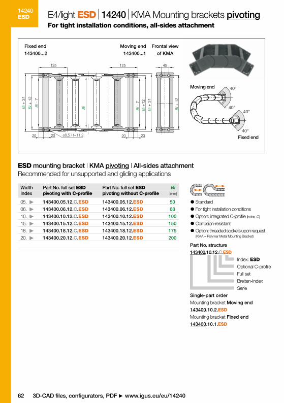
143400.10.2.ESD
143400.10.1.ESD
62
143400.10.12.C.ESD
14240ESD
Bi[mm]
50
68
100
150
175
200
05.
06.
10.
15.
18.
20.
143400.05.12.C.ESD
143400.06.12.C.ESD
143400.10.12.C.ESD
143400.15.12.C.ESD
143400.18.12.C.ESD
143400.20.12.C.ESD
143400.05.12.ESD
143400.06.12.ESD
143400.10.12.ESD
143400.15.12.ESD
143400.18.12.ESD
143400.20.12.ESD
125
20
Bi +
31
Bi +
12
Bi
Bi +
12
Bi +
31
Bi -
7
Bi -
7
125
2020 20
Bi +
12
45
ø8,5 / t=11,2
40°
40°
40°
40°
143400...2 143400...1
3D-CAD files, configurators, PDF www.igus.eu/eu/14240
Part No. structure
Index: ESD
Optional C-profile
Full set
Breiten-Index
Serie
Single-part order
Mounting bracket Moving end
Mounting bracket Fixed end
Standard
For tight installation conditions
Option: integrated C-profile (Index .C)
Corrosion-resistant
Option: threaded sockets upon request(KMA = Polymer Metal Mounting Bracket)
ESD mounting bracket | KMA pivoting | All-sides attachmentRecommended for unsupported and gliding applications
E4/light ESD 14240 KMA Mounting brackets pivotingFor tight installation conditions, all-sides attachment
Width Index
Part No. full set ESDpivoting with C-profile
Part No. full set ESDpivoting without C-profile
Moving end
Fixed end
Fixed end Moving end Frontal view
of KMA
D-EU-ESD KATALOG ICON 23.11.2011 15:09 Uhr Seite 62

63
14240ESD
igus® GmbH 51147 Cologne | Phone +49- (0) 22 03-96 49-800 Fax -222 | [email protected] | www.igus.eu
E4/light ESD Series 14240 My Sketches
D-EU-ESD KATALOG ICON 23.11.2011 15:09 Uhr Seite 63

6464
15050.
15050.
15050.
15050.
15050.
15050.
07
12
15
20
25
30
.R.0.ESD
.R.0.ESD
.R.0.ESD
.R.0.ESD
.R.0.ESD
.R.0.ESD
BaBiBaBiBaBiBaBi
72max. 80 10
8
Ba[mm]
Bi[mm]
105
155
180
230
280
330
75
125
150
200
250
300
| 150 | 200 | 250 |
| 150 | 200 | 250 |
| 150 | 200 | 250 |
| 150 | 200 | 250 |
| 150 | 200 | 250 |
| 150 | 200 | 250 |
15050. 20. 150.0.ESD
15050ESD 80
4
18
80.1.ESD
80.1.1.ESD
150500.07. .12.C.ESD
150500.12. .12.C.ESD
150500.15. .12.C.ESD
150500.20. .12.C.ESD
150500.25. .12.C.ESD
150500.30. .12.C.ESD******
Index: ESD, color grey
Bending radius R
Width index (depends on Bi)
Series / Type
Order key
R Bending radii[mm]
Available from stock. Delivery in 24h or today!* *Delivery time means time until shipping of goods
E4/light ESD Series 15050 Product range
ESD e-chains® | Series 15050 with crossbars every link
ESD e-chains® | Series 15050 | Interior separation | Standard
3D-CAD files, configurators, PDF www.igus.eu/eu/15050
Supplement Part No. with required radius (R) Example: 15050.20.150.0.ESD
ESD e-chains®
from stock*
Standard separator ESDFor all applications. Maximum locking strength
and safe standing in e-chains®. In the standard
configuration separators are assembled every 2nd
e-chain® link! More interior separators upon request.
KMA mounting brackets ESDpivoting, from stock**
Note: see
mounting brackets
*
Slotted separator
ESD
unassembled
assembled
D-EU-ESD KATALOG ICON 23.11.2011 15:09 Uhr Seite 64

0 2.0 4.0 6.0 8.0 10 12
0
0.5
1.0
1.5
2.04.0
8.0
20
30
40
50
85
6065
75
0 0.5 1.0 2.0 3.0 4.0 5.0 6.01.5 2.5 4.5 5.5
FLG
FLB
10
3.5
D
H
H -
108R
S/2
S
108
91
HF
= H
+ 6
0
FLG
FLB
H
HF
S (FLG)
S (FLB)
R 150 200 250
H -0+25 410 510 610
D 300 350 400
K 750 900 1050
65
15050ESD
Moving end
Fixed end
Fill
wei
ght
[kg
/m]
Unsupported length FLG / FLB [m]
Length of travel S [m]
Example
Fill weight = 15 [kg/m]
Unsupported length FLB = 3,5 m
Length of travel = 7,0 m
The required clearance height: HF = H + 60 mm (with 3,0 kg/m fill weight)
igus® GmbH 51147 Cologne | Phone +49- (0) 22 03-96 49-800 Fax -222 | [email protected] | www.igus.eu
E4/light ESD Series 15050 Dimensions Unsupported
Pitch = 91 mm/link Links/m = 11 (1001 mm)Chain length= S/2 + K
Speed, material, temperature and
flammability class page 59
Technical Data
Unsupported e-chains® feature positive
camber over short travels. This must be
accounted for when specifying the clea-
rance height HF. Please consult igus® if
space is particularly restricted.
The diagrams for unsupported length are appli-cable for the standard e-chains® in the igumid GLWmaterial. The values can also be used for the asses-sment of e-chain® applications in special materialESD. If the respective maximum unsupported lengthexceeds 80%, the suitability of the e-chain® shouldbe verified by a practice-oriented test.
Unsupported applications
FLG = with straight upper runFLB = with permitted sag
S = Length of travelR = Bending radius
H = Nominal clearance heightHF = Required clearance height
D = Overlength e-chain®, radius in final positionK = π • R + "safety"
D-EU-ESD KATALOG ICON 23.11.2011 15:09 Uhr Seite 65

150500.20.2.ESD
150500.20.1.ESD
66
150500.20.12.C.ESD
15050ESD
Bi[mm]
75
125
150
200
250
300
07.
12.
15.
20.
25.
30.
150500.07.12.C.ESD
150500.12.12.C.ESD
150500.15.12.C.ESD
150500.20.12.C.ESD
150500.25.12.C.ESD
150500.30.12.C.ESD
150500.07.12.ESD
150500.12.12.ESD
150500.15.12.ESD
150500.20.12.ESD
150500.25.12.ESD
150500.30.12.ESD
Bi +
20
66125
35
9
Bi +
37
Bi +
20
Bi
Bi +
20
Bi +
37
Bi
Bi
125
3520 20ø9 / t=11,2
45°
45°
45°
45°
150500...2 150500...1
3D-CAD files, configurators, PDF www.igus.eu/eu/15050
Part No. structure
Index: ESD
Optional C-profile
Full set
Width index
Serie
Single-part order
Mounting bracket Moving end
Mounting bracket Fixed end
Standard
For tight installation conditions
Option: integrated C-profile (Index .C)
Corrosion-resistant
Option: threaded sockets upon request(KMA = Polymer Metal Mounting Bracket)
ESD mounting bracket | KMA pivoting | All-sides attachmentRecommended for unsupported and gliding applications
E4/light ESD 15050 KMA Mounting brackets pivotingFor tight installation conditions, all-sides attachment
Width Index
Part No. full set ESDpivoting with C-profile
Part No. full set ESDpivoting without C-profile
Moving end
Fixed end
Fixed end Moving end Frontal view
of KMA
D-EU-ESD KATALOG ICON 23.11.2011 15:09 Uhr Seite 66

67
15050ESD
100
40 45
12
70
Bi -
24
Bi -
24
34
8
100
15
15
15050.10 15050.21
15050.11 15050.20
30°
30°
30°
30°
30°
30°
30°
30°
15050.2 15050.1
15050.12
15050.12.E
15050.2
15050.1
igus® GmbH 51147 Cologne | Phone +49- (0) 22 03-96 49-800 Fax -222 | [email protected] | www.igus.eu
Note: By ordering steel mounting brackets in combination
with an e-chain®, they will be delivered assembled!
E4/light ESD 15050 Steel Mounting brackets pivotingElectrically conductive
For pivoting connections
Secure connection
One part (two-piece) for
all e-chain® widths
Electrically conductive
Stainless steel version available -
please add index .E(Material: stainless steel 1.4301)
Mounting bracket | Steel pivotingRecommended for unsupported, vertical hanging and standing applications
Moving end
Fixed end
Moving end Fixed end
Part No. Mounting bracket
Full attachment set (both sides) for e-chain®,
4 parts, 2 with pin / 2 with bore
Stainless steel - full attachment set (both sides) for e-chain®,
4 parts, 2 with pin / 2 with bore
Mounting bracket set Moving end. 2 parts: 1 part left, 1 part right
Mounting bracket set Fixed end. 2 parts: 1 part left, 1 part right
Possible installation conditions - further installation angles installation sketch
D-EU-ESD KATALOG ICON 23.11.2011 15:09 Uhr Seite 67

68
1. Technical Data see catalog information
2. General safety informationThese additional Operating Instructions apply to theexplosion-protected versions of our e-chains® of Type"ESD" in color gray (similar to RAL 7015). They sup-plement the Installation Instructions for the standard e-chains® and the catalog information. The information inthese instructions relates only to data impacting onexplosion protection. The technical information in theInstallation Instructions for the standard e-chains® andthe category information still apply unchanged unlessthese Instructions explicitly exclude or replace the rele-vant information. Required documentation and otherdocuments are filed with the following institute pursuantto the ATEX Directive: Physikalisch-Technische Bundesanstalt (PTB) Braunschweig and BerlinBundesallee 100 • 38116 Braunschweig/Germany
3. Assembly, removal and installationPlease follow the information in the Installation Instruc-tions for the standard e-chains® and the catalog infor-
mation on assembly, removal and installation for trouble-free operation. igus® ESD e-chains® must be groundedwith appropriate measures in accordance with drawingnumber: 18392.2 in order to discharge any electrostaticcharges occurring. Assembly, installation, commis-sioning and maintenance may be performed onlyby "personnel trained in explosion protection"!Plea-se also note the corresponding national safety regula-tions and the relevant national regulations in respect ofexplosion protection during assembly and operation.
4. CommissioningBefore commissioning the system, check that thesystem has been installed correctly in accordance withthe Installation Instructions for the standard e-chains®
and the catalog information.Correct grounding mustbe checked in particular in the case of ESD e-chains®.
5. Maintenanceigus® e-chains® are maintenance-free. Correct groun-ding of the e-chains® must be inspected at regular inter-vals. (*in case of large projects a customized maintenance plans can become an
issue and will be created if necessary )
ESD&ATEX...Oper
Mounting brackets (moving end and fixed end) elec-trically conductive (e.g. ESD material or metal)
Electrically conductive base sur-face or guide troughs electrical-ly conductive (i.e. metal)
e-chain®
ESD material
e-chain®
ESD material
Supplement to installation instructions and catalog information for igus® ESD e-chains® – classification: II 2 GD
Connection of an e-chain®
in accordance with ATEX
Directive 94/9/EC
D-EU-ESD KATALOG ICON 23.11.2011 15:09 Uhr Seite 68

69
erating InstructionsEC-Declaration of ConformityDocument-No.: QM-0-419-AManufacturer: igus® GmbH • Spicher Str. 1a • 51147 KölnDescription of product: igus® ESD e-chains®
Description of product:ESD e-chains® (non-electrical components) used for dynamic guidance of energy conductors suchas lines and hoses with defined bending radii and travel parameters. The conformity rating was per-formed on the basis of ATEX Directive 94/9/EC according to Art. No. 8 (1) b) ii). The correspondingdocuments are filed at the following institute in compliance with the ATEX Directive:Physikalisch-Technische Bundesanstalt (PTB) Braunschweig und Berlin • Bundesallee 100 • D-38116 Braunschweig, Germany
Investigations required after classification II 2 GD in accordance with the standards and regula-tions listed below were conducted and verified by the PTB: Cenelec TR 50404:2003 previously:DIN 53482/VDE0303/Part 3, verified by the PTB), BGR 132:2003 and ZH1/200
Kennzeichnung: II 2 GD - Special color of the ESD e-chain®
color: gray (similar to RAL 7015)
The Declaration of Conformity refers only to conception and manufacture of the devices descri-bed above according to ATEX Directive 94/9/EC in compliance with the Harmonized StandardDIN EN 13463 – 1 (2002). The related Operating Instructions contain important safety instructions for positioning and com-missioning of igus® ESD e-chains® according to the ATEX Directive.
We hereby declare that igus® ESD e-chains® fulfill the requirements of the Directive specified above.
igus® Cologne, Germany, 27 May 2003
Chief Executive Officer
D-EU-ESD KATALOG ICON 23.11.2011 15:09 Uhr Seite 69

70
7 to 8 plus Saturday serviceOver 80,000 products ex-stock! Order 0.1 m of chain-flex® cable, just one e-chain® link or two bearings with-out surcharges. Invoices and acknowledgementsavailable by post, fax or e-mail. There are 1,900employees in Germany and 30 international subsi-diaries and offices, plus bases in another 42 coun-tries to guarantee a rapid delivery worldwide.● Delivery and consultation daily from
7 am to 8 pm, Saturday from 8 am to 12 pm● No minimum order values● No surcharges● Order tracking on the Internet right
up to the point of delivery● Simple returns procedure
i-net customer information systemAt: www.igus.eu track your orders in real time withigus® i-net. Just request a password, log into i-netand track your jobstatus via a webcam. igus® i-netshipment tracking permits a monitoring of deliveriesfrom igus® outlet right up to your doorstep. ● Detailed order data including an overview of
target and actual deadlines● Order confirmation via post,
fax or e-mail as required● Track your orders via webcam
igus® delivery service -No minimum order quantities, no surcharges.www.igus.eu/eu/deliveryservice
QuickLink - igus® e-chains® on the Internet! Go online and make use of all advantages atwww.igus.eu or every product in this catalog, thereis a special QuickLink or direct online pointer to fur-ther useful details, data and facts. These include:● Application videos and pictures● Assembly instructions● 3D-CAD files, DXF data● Comparisons and selection aids● Online configuration tools● Online wizard for calculations of service life● PDF-data and other formats for download:
ePlan-Download
igus®...service
D-EU-ESD KATALOG ICON 23.11.2011 15:09 Uhr Seite 70

71
1BiBa
hi ha5
6
7
8
9
2
3
[m]
kg
412
3
0.5
1.5
0
1.0
0
2.0
6.0
0.5 1 21.5 2.5
4.0
0 1 2 43 5
FLG
FLB
[m]
R B
A
Selection guide Designing e-chains®
If there is suitability for "unsupported straight", then the selection follows the following criteria:
You can choose the next and
more stable e-chain®, that can
be operated "unsupported".
You can design your
application to be "gliding".
The following options are available if there is no pos-sibility of self-supporting e-chain® application:
You can contact us directly or fax us your
e-chain® requests! We will respond immediately!
e-chain® Part No: ________ . _______ . ________ ._____
Alternative e-chain®-dimensions:
hi: ________ Bi: ________ ha: _________ Ba: _________
Fill weight: ______________________________________ kg/m
Length of travel: ____________________________________ m
Your Phone: ____________________________________________
Your Fax: ____________________________________________
Phone (+49) 0 22 03 - 96 49-0
Fax (+49) 0 22 03 - 96 49-222
Internet www.igus.eu/eu/finder
or
Opening Principle - The quick selec-
tion gives you an overview of the type
offilling potential of the e-chain®.
Determine the possible Bending
Radius R [mm] of the e-chain®
with respect to the cable diameter.
Interior separation is possible with…
Separators Full-width shelves Shelves
The price index gives you the possibility of making
price comparisons of similar sizes within the igus® range
Low Medium Highest
Additional criteria - for the appropriate selection of
your e-chains® such as pitch, permissible tempera-
tures etc. are available under quick selection.
Dimensioning e-chains®
Determine the size of the e-chain® based on the specified installation space of your machine
and/or of the selected filling (such as the number of cables/outer diameter of cable).
Determine fill weightDetermine fill weight of (cables and/or media hoses) in [kg/m]
using chainflex® Quick Selectionor manufacturer specification.
Determine length of travelCompare the fill weight calculated in (point ) to the maximum fill weight
of the selected e-chain® and check suitability for "unsupported application".
Unsupported lengthThe maximum unsupported length initially depends on the fill weight and the e-chain® selected. At the
same time, there are three different levels of unsupported length: FLG - Recommended Range of
Application FLB - Permitted Sag Critical Sag: Should never be operative installation! Twice
the value of the unsupported length determines the maximum travel in the "unsupported" type of ope-
ration. For evaluation the weight of the cables to be carried must be known, then an exact evaluation
can be made using a diagram on the introductory page of the selected product. You will find the values
for FLG and FLB in table form on the following pages of this chapter and for each Series in the cata-
log. They are necessary for: Finding the fill weight and length of travel for the appropriate e-chain®
Identifying the maximum load of the e-chain® used.
D-EU-ESD KATALOG ICON 23.11.2011 15:09 Uhr Seite 71

plas
tics.
..®.eu/..
®.eu/24
®.eu/8.00pm
®.eu/ready
/9001.2008Certified according to DIN ISO 9001:2008
igus® GmbH Spicher Str. 1a 51147 ColognePhone. +49-2203-9649-0 Fax [email protected] www.igus.eu
Online shopping – 24h! www.igus.eu/24
Ask for fully harnessed and preassembled readychains® - increase your cash-flow and profit immediately. www.readychain.eu
Ordering and deliveries weekdays from 7.00 am - 8.00 pm,Saturday from 8.00 am - 12.00 pm. No minimum orderquantities, no surcharges. Prompt delivery.www.igus.eu Phone +49-2203-9649-800 Fax -222
© igus® GmbH - 12/2011 - Subject to technical alterations!MAT0071824.20, Issue 12/2011
D-EU-ESD KATALOG ICON 23.11.2011 15:09 Uhr Seite 72