dynamically tunable hemispherical electronic eye camera ... · dynamically tunable hemispherical...
TRANSCRIPT
Dynamically tunable hemispherical electronic eyecamera system with adjustable zoom capabilityInhwa Junga, Jianliang Xiaoa, Viktor Malyarchuka, Chaofeng Lub,c, Ming Lic,d, Zhuangjian Liue, Jongseung Yoona,Yonggang Huangc,f,1, and John A. Rogersa,1
aDepartment of Materials Science and Engineering, Beckman Institute for Advanced Science and Technology, and Frederick Seitz Materials ResearchLaboratory, University of Illinois at Urbana-Champaign, Urbana, IL 61801; bDepartment of Civil Engineering, Zhejiang University, Hangzhou, Zhejiang310058, China; cDepartment of Civil and Environmental Engineering, Northwestern University, Evanston, IL 60208; dState Key Laboratory of StructuralAnalysis for Industrial Equipment, Dalian University of Technology, Dalian 116024, China; eInstitute of High Performance Computing, 1 Fusionopolis Way,#16-16 Connexis, Singapore 138632; and fDepartment of Mechanical Engineering, Northwestern University, Evanston, IL 60208
Edited by Eli Yablonovitch, University of California, Berkeley, CA, and approved December 10, 2010 (received for review October 14, 2010)
Imaging systems that exploit arrays of photodetectors in curvi-linear layouts are attractive due to their ability to match thestrongly nonplanar image surfaces (i.e., Petzval surfaces) that formwith simple lenses, thereby creating new design options. Recentwork has yielded significant progress in the realization of such“eyeball” cameras, including examples of fully functional silicon de-vices capable of collecting realistic images. Although these systemsprovide advantages compared to those with conventional, planardesigns, their fixed detector curvature renders them incompatiblewith changes in the Petzval surface that accompany variable zoomachieved with simple lenses. This paper describes a class of digitalimaging device that overcomes this limitation, through the use ofphotodetector arrays on thin elastomeric membranes, capable ofreversible deformation into hemispherical shapes with radii ofcurvature that can be adjusted dynamically, via hydraulics. Combin-ing this type of detector with a similarly tunable, fluidic plano-convex lens yields a hemispherical camera with variable zoom andexcellent imaging characteristics. Systematic experimental and the-oretical studies of the mechanics and optics reveal all underlyingprinciples of operation. This type of technology could be usefulfor night-vision surveillance, endoscopic imaging, and other areasthat require compact cameras with simple zoom optics and wide-angle fields of view.
biomimetic ∣ electronic eyeball camera ∣ flexible electronics ∣fluidic tunable lens ∣ hydraulic actuation
Mammalian eyes provide the biological inspiration for hemi-spherical cameras, where Petzval-matched curvature in the
photodetector array can dramatically simplify lens design withoutdegrading the field of view, focal area, illumination uniformity, orimage quality (1). Such systems use photodetectors in curvilinearlayouts due to their ability to match the strongly nonplanar imagesurfaces (i.e., Petzval surfaces) that form with simple lenses (2–4).Historical interest in such systems has culminated recently withthe development of realistic schemes for their fabrication, viastrategies that overcome intrinsic limitations associated with theplanar operation of existing semiconductor processes (4–6). Themost promising procedures involve either direct printing ofdevices and components onto curved surfaces (6) or geometricaltransformation of initially planar systems into desired shapes(1, 7–9). All demonstrated designs involve rigid, concave devicesubstrates, to achieve improved performance compared to planarcameras when simple lenses with fixed magnification are used.Interestingly, biology and evolution do not provide guides forachieving the sort of large-range, adjustable zoom capabilitiesthat are widely available in man-made cameras. The most rele-vant examples are in avian vision, where shallow pits in the retinalead to images with two fixed levels of zoom (50% high magni-fication in the center of the center of the field of view) (10). Also,changes in imaging properties occur, but in an irreversible fash-ion, during metamorphosis in amphibian vision to accommodatetransitions from aquatic to terrestrial environments (11).
The challenge in hemispherical imagers is that, with simpleoptics, the curvature of the Petzval surface changes with magni-fication in a manner that leads to mismatches with the shape ofdetector array. This behavior strongly degrades the imagingperformance, thereby eliminating any advantages associated withthe hemispherical detector design. The solution to this problemdemands that the curvature of the detector array changes in acoordinated manner with the magnification, to ensure identicalshapes for the image and detector surfaces at all zoom settings.In the following, we report a system that accomplishes this out-come by use of an array of interconnected silicon photodetectorson a thin, elastomeric membrane, in configurations that build onadvanced concepts of stretchable electronics (12–14). Actuatinga fluidic chamber beneath the membrane causes it to expand orcontract in a linear elastic, reversible fashion that providesprecise control of the radius of curvature. Integrating a similarlyactuated fluidic plano-convex lens yields a complete, hemisphe-rical camera system with continuously adjustable zoom.
Results and DiscussionFig. 1A provides a schematic illustration of the elements of thedevice and Fig. 1B shows a picture of an integrated system. Theupper and lower components correspond to an adjustable, plano-convex zoom lens and a tunable, hemispherical detector array,respectively. The lens uses adapted versions of similar compo-nents described elsewhere (15–18); it consists of a water-filledcavity (1-mm thick, in the planar, unpressurized state) betweena thin (0.2 mm) membrane of the transparent elastomer poly(dimethylsiloxane) (PDMS) on top and a glass window (1.5-mmthick) underneath. Pumping water into this cavity deforms theelastomer into a hemispherical shape, with a radius of curvaturethat depends on the pressure. This curvature, together with theindex of refraction of the PDMS and water, defines the focallength of the lens and, therefore, the magnification that it canprovide. Fig. 1C shows images of the detector array viewedthrough the fluidic lens, at two different positive pressures. Thechanges in magnification evident in Fig. 1C are reversible and canbe quantified through measurement and mechanics modeling.Fig. 1D presents side view images and data collected at variousstates of deformation. The lens adopts an approximately hemi-spherical shape for all tuning states, with an apex height andradius of curvature (RL) that change with pressure in a manner
Author contributions: I.J., J.X., V.M., Y.H., and J.A.R. designed research; I.J., J.X., V.M., C.L.,M.L., Z.L., J.Y., Y.H., and J.A.R. performed research; I.J., J.X., V.M., C.L., M.L., Z.L., J.Y., Y.H.,and J.A.R. contributed new reagents/analytic tools; I.J., J.X., V.M., C.L., M.L., Z.L., J.Y., Y.H.,and J.A.R. analyzed data; and I.J., J.X., V.M., Y.H., and J.A.R. wrote the paper.
The authors declare no conflict of interest.
This article is a PNAS Direct Submission.1To whom correspondence may be addressed. E-mail: [email protected] or [email protected].
This article contains supporting information online at www.pnas.org/lookup/suppl/doi:10.1073/pnas.1015440108/-/DCSupplemental.
1788–1793 ∣ PNAS ∣ February 1, 2011 ∣ vol. 108 ∣ no. 5 www.pnas.org/cgi/doi/10.1073/pnas.1015440108
Dow
nloa
ded
by g
uest
on
Mar
ch 5
, 202
0
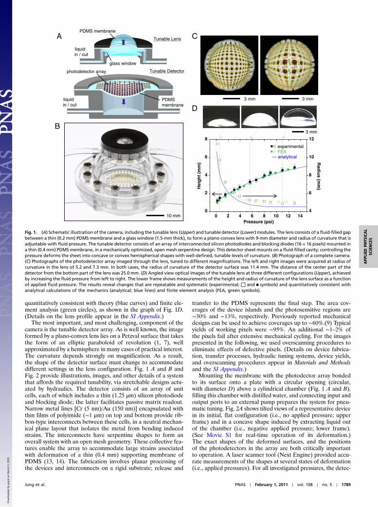
quantitatively consistent with theory (blue curves) and finite ele-ment analysis (green circles), as shown in the graph of Fig. 1D.(Details on the lens profile appear in the SI Appendix.)
The most important, and most challenging, component of thecamera is the tunable detector array. As is well known, the imageformed by a plano-convex lens lies on a Petzval surface that takesthe form of an elliptic paraboloid of revolution (1, 7), wellapproximated by a hemisphere in many cases of practical interest.The curvature depends strongly on magnification. As a result,the shape of the detector surface must change to accommodatedifferent settings in the lens configuration. Fig. 1 A and B andFig. 2 provide illustrations, images, and other details of a systemthat affords the required tunability, via stretchable designs actu-ated by hydraulics. The detector consists of an array of unitcells, each of which includes a thin (1.25 μm) silicon photodiodeand blocking diode; the latter facilitates passive matrix readout.Narrow metal lines [Cr (5 nm)/Au (150 nm)] encapsulated withthin films of polyimide (∼1 μm) on top and bottom provide rib-bon-type interconnects between these cells, in a neutral mechan-ical plane layout that isolates the metal from bending inducedstrains. The interconnects have serpentine shapes to form anoverall system with an open mesh geometry. These collective fea-tures enable the array to accommodate large strains associatedwith deformation of a thin (0.4 mm) supporting membrane ofPDMS (13, 14). The fabrication involves planar processing ofthe devices and interconnects on a rigid substrate; release and
transfer to the PDMS represents the final step. The area cov-erages of the device islands and the photosensitive regions are∼30% and ∼13%, respectively. Previously reported mechanicaldesigns can be used to achieve coverages up to ∼60%.(9) Typicalyields of working pixels were ∼95%. An additional ∼1–2% ofthe pixels fail after extensive mechanical cycling. For the imagespresented in the following, we used overscanning procedures toeliminate effects of defective pixels. (Details on device fabrica-tion, transfer processes, hydraulic tuning systems, device yields,and overscanning procedures appear in Materials and Methodsand the SI Appendix.)
Mounting the membrane with the photodector array bondedto its surface onto a plate with a circular opening (circular,with diameter D) above a cylindrical chamber (Fig. 1 A and B),filling this chamber with distilled water, and connecting input andoutput ports to an external pump prepares the system for pneu-matic tuning. Fig. 2A shows tilted views of a representative devicein its initial, flat configuration (i.e., no applied pressure; upperframe) and in a concave shape induced by extracting liquid outof the chamber (i.e., negative applied pressure; lower frame).(See Movie S1 for real-time operation of its deformation.)The exact shapes of the deformed surfaces, and the positionsof the photodetectors in the array are both critically importantto operation. A laser scanner tool (Next Engine) provided accu-rate measurements of the shapes at several states of deformation(i.e., applied pressures). For all investigated pressures, the detec-
APDMS membrane
glass window
liquid in / out
PDMSmembrane
photodetector array
liquid in / out
B
D
Tunable Lens
Tunable Detector
10 mm
3 mm 3 mm
C
3 mm
0 2 4 6 8 10 12 140
2
4
6
8
Pressure (psi)
Hei
gh
t (m
m)
4
6
8
10
12
Rad
ius (m
m)
experimentalFEA
— analytical
Fig. 1. (A) Schematic illustration of the camera, including the tunable lens (Upper) and tunable detector (Lower) modules. The lens consists of a fluid-filled gapbetween a thin (0.2 mm) PDMS membrane and a glass window (1.5-mm thick), to form a plano-convex lens with 9-mm diameter and radius of curvature that isadjustable with fluid pressure. The tunable detector consists of an array of interconnected silicon photodiodes and blocking diodes (16 × 16 pixels) mounted ina thin (0.4 mm) PDMSmembrane, in a mechanically optimized, open mesh serpentine design. This detector sheet mounts on a fluid-filled cavity; controlling thepressure deforms the sheet into concave or convex hemispherical shapes with well-defined, tunable levels of curvature. (B) Photograph of a complete camera.(C) Photographs of the photodetector array imaged through the lens, tuned to different magnifications. The left and right images were acquired at radius ofcurvature in the lens of 5.2 and 7.3 mm. In both cases, the radius of curvature of the detector surface was 11.4 mm. The distance of the center part of thedetector from the bottom part of the lens was 25.0 mm. (D) Angled view optical images of the tunable lens at three different configurations (Upper), achievedby increasing the fluid pressure from left to right. The lower frame shows measurements of the height and radius of curvature of the lens surface as a functionof applied fluid pressure. The results reveal changes that are repeatable and systematic (experimental; □ and ▪ symbols) and quantitatively consistent withanalytical calculations of the mechanics (analytical; blue lines) and finite element analysis (FEA, green symbols).
Jung et al. PNAS ∣ February 1, 2011 ∣ vol. 108 ∣ no. 5 ∣ 1789
APP
LIED
PHYS
ICAL
SCIENCE
S
Dow
nloa
ded
by g
uest
on
Mar
ch 5
, 202
0
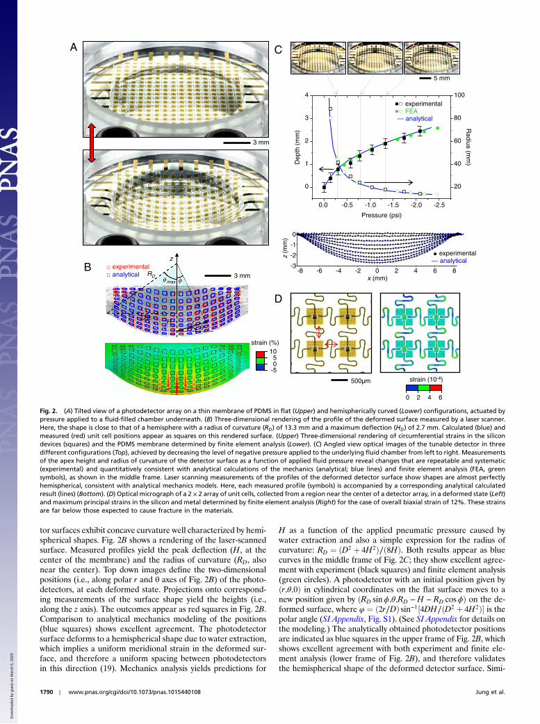
tor surfaces exhibit concave curvature well characterized by hemi-spherical shapes. Fig. 2B shows a rendering of the laser-scannedsurface. Measured profiles yield the peak deflection (H, at thecenter of the membrane) and the radius of curvature (RD, alsonear the center). Top down images define the two-dimensionalpositions (i.e., along polar r and θ axes of Fig. 2B) of the photo-detectors, at each deformed state. Projections onto correspond-ing measurements of the surface shape yield the heights (i.e.,along the z axis). The outcomes appear as red squares in Fig. 2B.Comparison to analytical mechanics modeling of the positions(blue squares) shows excellent agreement. The photodetectorsurface deforms to a hemispherical shape due to water extraction,which implies a uniform meridional strain in the deformed sur-face, and therefore a uniform spacing between photodetectorsin this direction (19). Mechanics analysis yields predictions for
H as a function of the applied pneumatic pressure caused bywater extraction and also a simple expression for the radius ofcurvature: RD ¼ ðD2 þ 4H2Þ∕ð8HÞ. Both results appear as bluecurves in the middle frame of Fig. 2C; they show excellent agree-ment with experiment (black squares) and finite element analysis(green circles). A photodetector with an initial position given byðr;θ;0Þ in cylindrical coordinates on the flat surface moves to anew position given by ðRD sinϕ;θ;RD −H − RD cosϕÞ on the de-formed surface, where φ ¼ ð2r∕DÞ sin−1½4DH∕ðD2 þ 4H2Þ� is thepolar angle (SI Appendix, Fig. S1). (See SI Appendix for details onthe modeling.) The analytically obtained photodetector positionsare indicated as blue squares in the upper frame of Fig. 2B, whichshows excellent agreement with both experiment and finite ele-ment analysis (lower frame of Fig. 2B), and therefore validatesthe hemispherical shape of the deformed detector surface. Simi-
strain (%)1050
-5
A
B
3 mm
experimentalanalytical
D
strain (10-4)
0 2 4 6
500µm
z
rθ
C
5 mm
experimentalFEA
— analytical
φRD
D/2H
φmax
-8 -6 -4 -2 0 2 4 6 8-3
-2
-1
0
z(m
m)
x (mm)
0.0 -0.5 -1.0 -1.5 -2.0 -2.5
0
1
2
3
4
Pressure (psi)
Dep
th (
mm
)
20
40
60
80
100
Radius (m
m)
experimental— analytical
3 mm
Fig. 2. (A) Tilted view of a photodetector array on a thin membrane of PDMS in flat (Upper) and hemispherically curved (Lower) configurations, actuated bypressure applied to a fluid-filled chamber underneath. (B) Three-dimensional rendering of the profile of the deformed surface measured by a laser scanner.Here, the shape is close to that of a hemisphere with a radius of curvature (RD) of 13.3 mm and a maximum deflection (HD) of 2.7 mm. Calculated (blue) andmeasured (red) unit cell positions appear as squares on this rendered surface. (Upper) Three-dimensional rendering of circumferential strains in the silicondevices (squares) and the PDMS membrane determined by finite element analysis (Lower). (C) Angled view optical images of the tunable detector in threedifferent configurations (Top), achieved by decreasing the level of negative pressure applied to the underlying fluid chamber from left to right. Measurementsof the apex height and radius of curvature of the detector surface as a function of applied fluid pressure reveal changes that are repeatable and systematic(experimental) and quantitatively consistent with analytical calculations of the mechanics (analytical; blue lines) and finite element analysis (FEA, greensymbols), as shown in the middle frame. Laser scanning measurements of the profiles of the deformed detector surface show shapes are almost perfectlyhemispherical, consistent with analytical mechanics models. Here, each measured profile (symbols) is accompanied by a corresponding analytical calculatedresult (lines) (Bottom). (D) Optical micrograph of a 2 × 2 array of unit cells, collected from a region near the center of a detector array, in a deformed state (Left)and maximum principal strains in the silicon and metal determined by finite element analysis (Right) for the case of overall biaxial strain of 12%. These strainsare far below those expected to cause fracture in the materials.
1790 ∣ www.pnas.org/cgi/doi/10.1073/pnas.1015440108 Jung et al.
Dow
nloa
ded
by g
uest
on
Mar
ch 5
, 202
0
lar modeling can be used to define the distribution of strainsacross both the PDMS membrane and the array of silicon photo-diodes and blocking diodes. The results (Fig. 2B) show strains inboth materials that are far below their thresholds for fracture(>150% for PDMS; ∼1% for silicon). The overall computedshape of the system also compares well to measurement. Furtherstudy illustrates that this level of agreement persists across alltuning states, as illustrated in Fig. 2C. Finite element analysis(lower frame of Fig. 2B) shows that the serpentine interconnectshave negligible effects on the photodetector positions (20).Understanding their behavior is nevertheless important becausethey provide electrical interconnection necessary for operation.Three-dimensional finite element analysis of a square 2 × 2 clus-ter of four unit cells appears in Fig. 2D. The color shading showsthe maximum principal strains in the silicon and metal, whichare the most fragile materials in the detectors. The calculatedpeak strains in the materials are all exceptionally low, even forthis case where the overall biaxial strain is ∼12%, correspondingto the point of highest strain in the array when tuned to the mosthighly curved configuration.
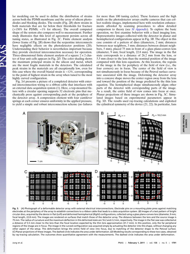
Fig. 3A presents a picture of a completed detector with exter-nal interconnection wiring to a ribbon cable that interfaces withan external data acquisition system (1). Here, a top-mounted fix-ture with a circular opening supports 32 electrode pins that me-chanically press against corresponding pads at the periphery ofthe detector array. A compression element with four cantileversprings at each corner ensures uniformity in the applied pressure,to yield a simple and robust interconnection scheme (no failures
for more than 100 tuning cycles). These features and the highyields on the photodetector arrays enable cameras that can col-lect realistic images, implemented here with resolution enhance-ments afforded by scanning procedures to allow detailedcomparison to theory (see SI Appendix). To explore the basicoperation, we first examine behavior with a fixed imaging lens.Representative images collected with the detector in planar andhemispherical configurations appear in Fig. 3B. The object in thiscase consists of a pattern of discs (diameters, 2 mm; distancesbetween near neighbors, 3 mm; distances between distant neigh-bors, 5 mm), placed 75 mm in front of a glass plano-convex lens(diameter, 9 mm; focal length, 22.8 mm). The image in the flatstate corresponds to a distance of 26.2 mm from the lens, or5.5 mm closer to the lens than the nominal position of the imagecomputed with thin lens equations. At this location, the regionsof the image in the far periphery of the field of view (i.e., thefour corners) are in focus. The center of the field of view isnot simultaneously in focus because of the Petzval surface curva-ture associated with the image. Deforming the detector arrayinto a concave shape moves the center region away from the lensand toward the position of the image predicted by the thin lensequation. The hemispherical shape simultaneously aligns otherparts of the detector with corresponding parts of the image.As a result, the entire field of view comes into focus at once.Planar projections of these images are shown in Fig. 3C. Simu-lated images based on experimental parameters appear inFig. 3D. The results used ray-tracing calculations and exploitedthe cylindrical symmetry of the device (21, 22). In particular, fans
A
5
0
-5
-50
0 3RD = 16.2 mm
5
RD = ∞
5
0
-50
5
0 3
1 cm
C5
0
-5
-5 0 5 -5 0 5
5
0
-5
5
0
-5
-5 0 5
5
0
-5
-5 0 5
D
-5
B
Fig. 3. (A) Photograph of a deformable detector array with external electrical interconnections. Electrode pins on a mounting plate press against matchingelectrodes at the periphery of the array to establish connections to a ribbon cable that leads to a data acquisition system. (B) Images of a test pattern of brightcircular discs, acquired by the device in flat (Left) and deformed hemispherical (Right) configurations, collected using a glass plano-convex lens (diameter, 9 mm;focal length, 22.8 mm). The images are rendered on surfaces that match those of the detector array. The distance between the lens and the source image is75mm. The radius of curvature and themaximum deflection in this deformed state are 16.2 and 2.2mm, respectively. The image in the flat case was collected ata distance of 5.5 mm closer to the lens than the focal location expected by the thin lens approximation (31.7 mm). In this position, only the far peripheralregions of the image are in focus. The image in the curved configuration was acquired simply by actuating the detector into this shape, without changing anyother aspect of the setup. This deformation brings the entire field of view into focus, due to matching of the detector shape to the Petzval surface.(C) Planar projections of these images. The dashed circle indicates the area under deformation. (D) Modeling results corresponding to these two cases, obtainedby ray-tracing calculation. The outcomes show quantitative agreement with the measurements. The dashed circle indicates the area under deformation.
Jung et al. PNAS ∣ February 1, 2011 ∣ vol. 108 ∣ no. 5 ∣ 1791
APP
LIED
PHYS
ICAL
SCIENCE
S
Dow
nloa
ded
by g
uest
on
Mar
ch 5
, 202
0
of rays originating at the object (75 mm in front of the lens) werepropagated through the system to determine relevant pointspread functions (PSFs). Placing corresponding PSFs for everypoint at the object plane, using a total of 10,000 rays, onto thesurface of a screen defined by the shape of the detector yieldedimages suitable for direct comparison to experiment.
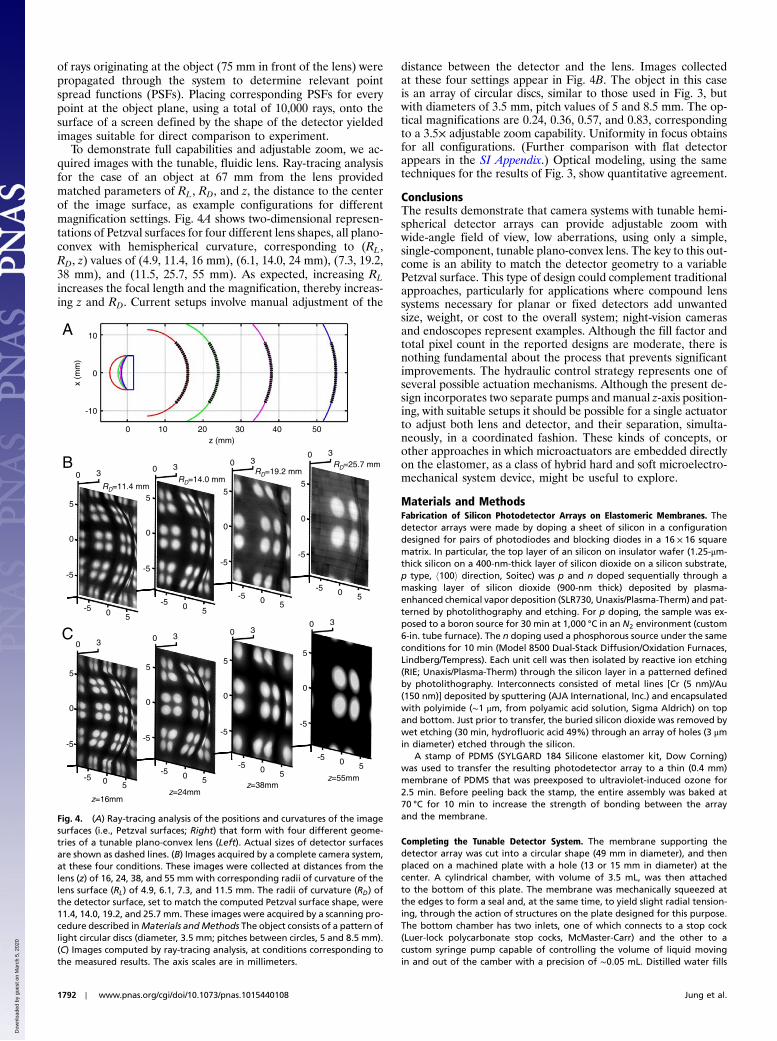
To demonstrate full capabilities and adjustable zoom, we ac-quired images with the tunable, fluidic lens. Ray-tracing analysisfor the case of an object at 67 mm from the lens providedmatched parameters of RL, RD, and z, the distance to the centerof the image surface, as example configurations for differentmagnification settings. Fig. 4A shows two-dimensional represen-tations of Petzval surfaces for four different lens shapes, all plano-convex with hemispherical curvature, corresponding to (RL,RD, z) values of (4.9, 11.4, 16 mm), (6.1, 14.0, 24 mm), (7.3, 19.2,38 mm), and (11.5, 25.7, 55 mm). As expected, increasing RLincreases the focal length and the magnification, thereby increas-ing z and RD. Current setups involve manual adjustment of the
distance between the detector and the lens. Images collectedat these four settings appear in Fig. 4B. The object in this caseis an array of circular discs, similar to those used in Fig. 3, butwith diameters of 3.5 mm, pitch values of 5 and 8.5 mm. The op-tical magnifications are 0.24, 0.36, 0.57, and 0.83, correspondingto a 3.5× adjustable zoom capability. Uniformity in focus obtainsfor all configurations. (Further comparison with flat detectorappears in the SI Appendix.) Optical modeling, using the sametechniques for the results of Fig. 3, show quantitative agreement.
ConclusionsThe results demonstrate that camera systems with tunable hemi-spherical detector arrays can provide adjustable zoom withwide-angle field of view, low aberrations, using only a simple,single-component, tunable plano-convex lens. The key to this out-come is an ability to match the detector geometry to a variablePetzval surface. This type of design could complement traditionalapproaches, particularly for applications where compound lenssystems necessary for planar or fixed detectors add unwantedsize, weight, or cost to the overall system; night-vision camerasand endoscopes represent examples. Although the fill factor andtotal pixel count in the reported designs are moderate, there isnothing fundamental about the process that prevents significantimprovements. The hydraulic control strategy represents one ofseveral possible actuation mechanisms. Although the present de-sign incorporates two separate pumps and manual z-axis position-ing, with suitable setups it should be possible for a single actuatorto adjust both lens and detector, and their separation, simulta-neously, in a coordinated fashion. These kinds of concepts, orother approaches in which microactuators are embedded directlyon the elastomer, as a class of hybrid hard and soft microelectro-mechanical system device, might be useful to explore.
Materials and MethodsFabrication of Silicon Photodetector Arrays on Elastomeric Membranes. Thedetector arrays were made by doping a sheet of silicon in a configurationdesigned for pairs of photodiodes and blocking diodes in a 16 × 16 squarematrix. In particular, the top layer of an silicon on insulator wafer (1.25-μm-thick silicon on a 400-nm-thick layer of silicon dioxide on a silicon substrate,p type, h100i direction, Soitec) was p and n doped sequentially through amasking layer of silicon dioxide (900-nm thick) deposited by plasma-enhanced chemical vapor deposition (SLR730, Unaxis/Plasma-Therm) and pat-terned by photolithography and etching. For p doping, the sample was ex-posed to a boron source for 30 min at 1,000 °C in an N2 environment (custom6-in. tube furnace). The n doping used a phosphorous source under the sameconditions for 10 min (Model 8500 Dual-Stack Diffusion/Oxidation Furnaces,Lindberg/Tempress). Each unit cell was then isolated by reactive ion etching(RIE; Unaxis/Plasma-Therm) through the silicon layer in a patterned definedby photolithography. Interconnects consisted of metal lines [Cr (5 nm)/Au(150 nm)] deposited by sputtering (AJA International, Inc.) and encapsulatedwith polyimide (∼1 μm, from polyamic acid solution, Sigma Aldrich) on topand bottom. Just prior to transfer, the buried silicon dioxide was removed bywet etching (30 min, hydrofluoric acid 49%) through an array of holes (3 μmin diameter) etched through the silicon.
A stamp of PDMS (SYLGARD 184 Silicone elastomer kit, Dow Corning)was used to transfer the resulting photodetector array to a thin (0.4 mm)membrane of PDMS that was preexposed to ultraviolet-induced ozone for2.5 min. Before peeling back the stamp, the entire assembly was baked at70 °C for 10 min to increase the strength of bonding between the arrayand the membrane.
Completing the Tunable Detector System. The membrane supporting thedetector array was cut into a circular shape (49 mm in diameter), and thenplaced on a machined plate with a hole (13 or 15 mm in diameter) at thecenter. A cylindrical chamber, with volume of 3.5 mL, was then attachedto the bottom of this plate. The membrane was mechanically squeezed atthe edges to form a seal and, at the same time, to yield slight radial tension-ing, through the action of structures on the plate designed for this purpose.The bottom chamber has two inlets, one of which connects to a stop cock(Luer-lock polycarbonate stop cocks, McMaster-Carr) and the other to acustom syringe pump capable of controlling the volume of liquid movingin and out of the camber with a precision of ∼0.05 mL. Distilled water fills
B
5
0
-5
-5 0 5
z=16mmz=24mm
z=38mmz=55mm
0 3RD=14.0 mm
RD=19.2 mmRD=25.7 mm
RD=11.4 mm5
0
-5
-5 0 5
0 3
5
0
-5
-5 0 5
0 3
5
0
-5
-5 0 5
0 3
C
5
0
-5
-5
0 3
5
0
-5
-5 0 5
0 3
5
0
-5
-5 0 5
0 3
5
0
-5
-5 0 5
0 3
0 5
A
z (mm)
x (m
m)
0 10 20 30 40 50
10
0
-10
Fig. 4. (A) Ray-tracing analysis of the positions and curvatures of the imagesurfaces (i.e., Petzval surfaces; Right) that form with four different geome-tries of a tunable plano-convex lens (Left). Actual sizes of detector surfacesare shown as dashed lines. (B) Images acquired by a complete camera system,at these four conditions. These images were collected at distances from thelens (z) of 16, 24, 38, and 55 mm with corresponding radii of curvature of thelens surface (RL) of 4.9, 6.1, 7.3, and 11.5 mm. The radii of curvature (RD) ofthe detector surface, set to match the computed Petzval surface shape, were11.4, 14.0, 19.2, and 25.7 mm. These images were acquired by a scanning pro-cedure described inMaterials andMethods The object consists of a pattern oflight circular discs (diameter, 3.5 mm; pitches between circles, 5 and 8.5 mm).(C) Images computed by ray-tracing analysis, at conditions corresponding tothe measured results. The axis scales are in millimeters.
1792 ∣ www.pnas.org/cgi/doi/10.1073/pnas.1015440108 Jung et al.
Dow
nloa
ded
by g
uest
on
Mar
ch 5
, 202
0
the system. A gauge (diaphragm gauge 0 ∼ 3 psi, Noshok) was used to moni-tor the pressure.
For electrical connection, the top insulating layers covering the electrodepads at the periphery of the detector array were removed by RIE (CS 1701Reactive Ion Etching System, Nordson MARCH) through an elastomericshadow mask. These electrodes press against copper electrode pins on amounting plate designed with four cantilever springs at its corners. To ensuregood electrical contact, the surfaces of the pins were polished and thencoated with metal layers by electron beam deposition [Cr (20 nm)/Au(400 nm)]. Each electrode pin was connected to an electrical wire usingconductive epoxy (CW2400, Chemtronics); these wires were assembled witha pin connector which connects to a ribbon cable.
Fabricating the Tunable Lens. The tunable lens simply consists of a thin PDMSmembrane (0.2 mm in thickness, 25.4 mm in diameter) and a glass window(12.5 mm in diameter, 1.5 mm in thickness; Edmund Optics) attached to aplastic supporting piece by epoxy (ITW Devcon). The separation betweenthe PDMS membrane and the glass window was ∼1 mm. To ensure a water-tight seal, the membrane was squeezed between two plastic plates. A hole inthe top plate defined the diameter of the lens (9 mm). Gauges (diaphragmgauge 0 ∼ 10 psi, Noshok; differential gauge 0 ∼ 20 psi, Orange Research)were used to measure the pressure.
Capturing Images. Diffusive light from an array of light emitting diodes(MB-BL4X4, Metaphase Technologies) provided a source for illumination.The objects consisted of printed transparency films (laser photoplotting,CAD/Art Services) or metal plates machined by laser cutting. In all cases,images were rendered by combining datasets collected by stepping thedetector along two orthogonal axes x, y normal to the optic axis. Either10 or 20 steps with spacings of 92 μm for each axis were used to achieveeffective resolutions of 100 times larger than the number of photodetectors.Lookup tables and automated computer codes were used, in some cases, toeliminate the effects of malfunctioning pixels.
ACKNOWLEDGMENTS. We thank T. Banks, and J.A.N.T. Soares for help usingfacilities at the Frederick Seitz Materials Research Laboratory. The authorsalso appreciate M.J. Kim, D. Stevenson, G. Shin, K.J. Yu, J.H. Lee, D.H. Kim,D.G. Kim, H.C. Ko, and J.S. Ha for valuable comments and help. The funda-mental aspects of hard and soft materials integration and the overall systemconstruction were supported by Defense Advanced Research PlanningAgency N66001-10-1-4008 and Sharp. The optical design and the theoreticalmechanics were supported by National Science Foundation EmergingFrontiers in Research and Innovation, and Electrical, Communications, andCyber Systems ECCS-0824129, respectively.
1. Ko HC, et al. (2008) A hemispherical electronic eye camera based on compressiblesilicon optoelectronics. Nature 454:748–753.
2. Grayson T (2002) Curved focal plane wide field of view telescope design. Proc SPIE4849:269–274.
3. Rim SB, et al. (2008) The optical advantages of curved focal plane arrays. Opt Express16:4965–4971.
4. Dinyari R, et al. (2008) Curving monolithic silicon for nonplanar focal plane arrayapplications. Appl Phys Lett 92:091114-1–091114-3.
5. Hung PJ, Jeong KH, Liu GL, Lee LP (2004) Microfabricated suspensions for electricalconnections on the tunable elastomer membrane. Appl Phys Lett 85:6051–6053.
6. Xu X, Davanco M, Qi XF, Forrest SR (2008) Direct transfer patterning on three dimen-sionally deformed surfaces at micrometer resolutions and its application to hemisphe-rical focal plane detector arrays. Org Electron 9:1122–1127.
7. Jung I, et al. (2010) Paraboloid electronic eye cameras using deformable arrays ofphotodetectors in hexagonal mesh layouts. Appl Phys Lett 96:021110-1–021110-3.
8. Ko HC, et al. (2009) Curvilinear electronics formed using silicon membrane circuits andelastomeric transfer elements. Small 5:2703–2709.
9. Shin G, et al. (2010) Micromechanics and advanced designs for curved photodetectorarrays in hemispherical electronic-eye cameras. Small 6:851–856.
10. Proctor NS, Lynch PJ (1993)Manual of Ornithology: Avian Structure and Function (YaleUniv Press, New Haven, CT).
11. Hoskins SG (1990) Metamorphosis of the amphibian eye. J Neurobiol 21:970–989.12. Khang DY, Jiang HQ, Huang Y, Rogers JA (2006) A stretchable form of single-crystal
silicon for high-performance electronics on rubber substrates. Science 311:208–212.
13. Kim DH, et al. (2009) Ultrathin silicon circuits with strain-isolation layers and meshlayouts for high-performance electronics on fabric, vinyl, leather, and paper. AdvMater 21:3703–3707.
14. Kim DH, et al. (2008) Materials and noncoplanar mesh designs for integrated circuitswith linear elastic responses to extreme mechanical deformations. Proc Natl Acad SciUSA 105:18675–18680.
15. Tsai FS, et al. (2008) Miniaturized universal imaging device using fluidic lens. Opt Lett33:291–293.
16. Tsai FS, et al. (2010) Fluidic lens laparoscopic zoom camera for minimally invasivesurgery. J Biomed Opt 15:030504-1–030504-3.
17. Yu HB, Zhou GY, Leung HM, Chau FS (2010) Tunable liquid-filled lens integrated withaspherical surface for spherical aberration compensation. Opt Express 18:9945–9954.
18. Zhang DY, et al. (2003) Fluidic adaptive lens with high focal length tunability. ApplPhys Lett 82:3171–3172.
19. Wang SD, et al. (2009) Mechanics of hemispherical electronics. Appl Phys Lett95:181912-1–181912-3.
20. Song J, et al. (2009) Mechanics of noncoplanar mesh design for stretchable electroniccircuits. J Appl Phys 105:123516-1–123516-6.
21. Born M, Wolf E (1999) Principles of Optics (Cambridge Univ Press, New York),pp 204–210.
22. Walther A (1995) The Ray and Wave Theory of Lenses (Cambridge Univ Press,Cambridge, UK), pp 283–294.
Jung et al. PNAS ∣ February 1, 2011 ∣ vol. 108 ∣ no. 5 ∣ 1793
APP
LIED
PHYS
ICAL
SCIENCE
S
Dow
nloa
ded
by g
uest
on
Mar
ch 5
, 202
0