dynamic simulation of a flexible pavement layers...
TRANSCRIPT

Transportation Geotechnics 7 (2016) 40–58
Contents lists available at ScienceDirect
Transportation Geotechnics
journal homepage: www.elsevier .com/ locate / t rgeo
Dynamic simulation of a flexible pavement layers consideringshakedown effects and soil-asphalt interaction
http://dx.doi.org/10.1016/j.trgeo.2016.04.0032214-3912/� 2016 Elsevier Ltd. All rights reserved.
⇑ Corresponding author. Tel.: +61 8 9266 4521; fax: +61 8 9266 4811.E-mail address: [email protected] (B. Ghadimi).
Behzad Ghadimi ⇑, Hamid Nikraz, Michele RosanoCurtin University, Australia
a r t i c l e i n f o
Article history:Received 27 October 2015Revised 30 March 2016Accepted 25 April 2016Available online 29 April 2016
Keywords:Flexible pavementDynamic simulationShakedownSoil-asphalt interaction
a b s t r a c t
This research evaluates the effects of shakedown and soil asphalt interaction on thedynamic simulation of flexible layered pavement structure. In a newly developed assess-ment methodology the shakedown concept is implemented for the granular layer underasphalt concrete. Under this assessment granular material behaviour changes from plasticto elastic as a function of the number of loading cycles. Interactional forces are consideredthrough contact elements placed between the base and the asphalt layer. A nonlinear stressdependent model in the elastic domain and the Mohr–Coulomb constitutive model in theplastic domain are utilised to simulate the behaviour of granular layers and the results ofthe simulation are validated with previously published literature. One static simulationand three different dynamic simulations under cyclic Haversine loading of a single tyredual axle are then compared with each other. The first dynamic simulation assumesMohr–Coulomb plasticity, the second simulation considers the shakedown effects andthe third simulation calculates soil asphalt interactional forces.
� 2016 Elsevier Ltd. All rights reserved.
Introduction The behaviour of granular materials can be divided into
In flexible pavement engineering the significant role ofthe granular layers in rutting failure is well known. Theinvestigation of the contribution of granular materials inrutting and surface deflection in accelerated pavementtests has been previously examined (Little, 1993;Pidwerbesky, 1996; Arnold et al., 2001; Korkiala-Tanttuet al., 2003). Based on this research, the layers containinggranular materials have been considered responsible for30–70% of the rutting deflection occurring at the surfaceof flexible pavements. The rutting itself is governed bythe permanent deformation and the residual plastic strainsinduced inside the granular body in each loading cycle.This is why the investigation of unbound granular materi-als (UGM) and their reaction to the cycles of traffic loadingis considered critical.
two parts: elastic range and plastic range performance.Whilst induced stress remains in the elastic domain,material behaviour can be modelled as linear elastic ornonlinear elastic. For UGM it is more realistic to considera stress dependent elastic modulus where elastic modulus(or resilient modulus) is not constant during theincrements of loading. Such an approach has been widelyused in previous research (Cho et al., 1996; Kim andTutumluer, 2006; Kim et al., 2009; Lee et al., 2009;Cortes et al., 2012; Ghadimi et al., 2013a,b,c). There is avariety of nonlinear constitutive models developedespecially for granular material assessment in flexiblepavement. Nonlinearity of granular material can be consid-ered through the dependency of the resilient modulus tothe strain tensor (Hjelmstad and Taciroglu, 2000;Taciroglu and Hjelmstad, 2002) to the bulk stress (Seedet al., 1962; Hicks and Monismith, 1971) or to the stressinvariants representing deviatoric and bulk stress condi-tions (Uzan, 1985; Witczak and Uzan, 1988). Amongst
B. Ghadimi et al. / Transportation Geotechnics 7 (2016) 40–58 41
forms of nonlinearity, the latter has found more interestamongst flexible pavement researchers where UGM beha-viour is largely defined as a function of deviatoric and bulkstress conditions simultaneously.
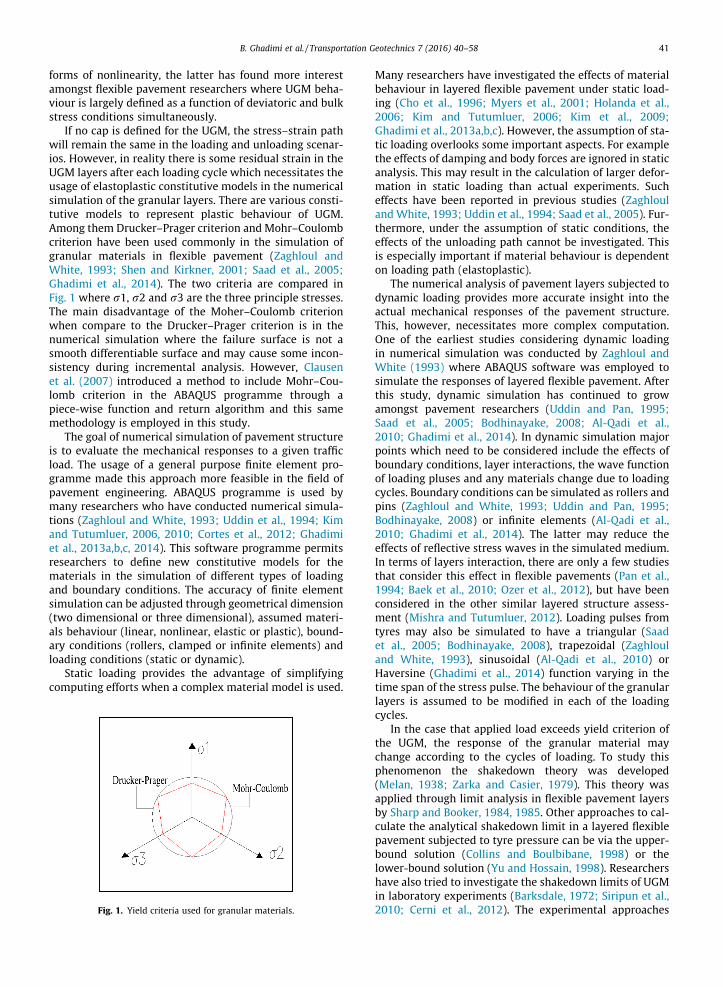
If no cap is defined for the UGM, the stress–strain pathwill remain the same in the loading and unloading scenar-ios. However, in reality there is some residual strain in theUGM layers after each loading cycle which necessitates theusage of elastoplastic constitutive models in the numericalsimulation of the granular layers. There are various consti-tutive models to represent plastic behaviour of UGM.Among them Drucker–Prager criterion and Mohr–Coulombcriterion have been used commonly in the simulation ofgranular materials in flexible pavement (Zaghloul andWhite, 1993; Shen and Kirkner, 2001; Saad et al., 2005;Ghadimi et al., 2014). The two criteria are compared inFig. 1 where r1, r2 and r3 are the three principle stresses.The main disadvantage of the Moher–Coulomb criterionwhen compare to the Drucker–Prager criterion is in thenumerical simulation where the failure surface is not asmooth differentiable surface and may cause some incon-sistency during incremental analysis. However, Clausenet al. (2007) introduced a method to include Mohr–Cou-lomb criterion in the ABAQUS programme through apiece-wise function and return algorithm and this samemethodology is employed in this study.
The goal of numerical simulation of pavement structureis to evaluate the mechanical responses to a given trafficload. The usage of a general purpose finite element pro-gramme made this approach more feasible in the field ofpavement engineering. ABAQUS programme is used bymany researchers who have conducted numerical simula-tions (Zaghloul and White, 1993; Uddin et al., 1994; Kimand Tutumluer, 2006, 2010; Cortes et al., 2012; Ghadimiet al., 2013a,b,c, 2014). This software programme permitsresearchers to define new constitutive models for thematerials in the simulation of different types of loadingand boundary conditions. The accuracy of finite elementsimulation can be adjusted through geometrical dimension(two dimensional or three dimensional), assumed materi-als behaviour (linear, nonlinear, elastic or plastic), bound-ary conditions (rollers, clamped or infinite elements) andloading conditions (static or dynamic).
Static loading provides the advantage of simplifyingcomputing efforts when a complex material model is used.
Fig. 1. Yield criteria used for granular materials.
Many researchers have investigated the effects of materialbehaviour in layered flexible pavement under static load-ing (Cho et al., 1996; Myers et al., 2001; Holanda et al.,2006; Kim and Tutumluer, 2006; Kim et al., 2009;Ghadimi et al., 2013a,b,c). However, the assumption of sta-tic loading overlooks some important aspects. For examplethe effects of damping and body forces are ignored in staticanalysis. This may result in the calculation of larger defor-mation in static loading than actual experiments. Sucheffects have been reported in previous studies (Zaghlouland White, 1993; Uddin et al., 1994; Saad et al., 2005). Fur-thermore, under the assumption of static conditions, theeffects of the unloading path cannot be investigated. Thisis especially important if material behaviour is dependenton loading path (elastoplastic).
The numerical analysis of pavement layers subjected todynamic loading provides more accurate insight into theactual mechanical responses of the pavement structure.This, however, necessitates more complex computation.One of the earliest studies considering dynamic loadingin numerical simulation was conducted by Zaghloul andWhite (1993) where ABAQUS software was employed tosimulate the responses of layered flexible pavement. Afterthis study, dynamic simulation has continued to growamongst pavement researchers (Uddin and Pan, 1995;Saad et al., 2005; Bodhinayake, 2008; Al-Qadi et al.,2010; Ghadimi et al., 2014). In dynamic simulation majorpoints which need to be considered include the effects ofboundary conditions, layer interactions, the wave functionof loading pluses and any materials change due to loadingcycles. Boundary conditions can be simulated as rollers andpins (Zaghloul and White, 1993; Uddin and Pan, 1995;Bodhinayake, 2008) or infinite elements (Al-Qadi et al.,2010; Ghadimi et al., 2014). The latter may reduce theeffects of reflective stress waves in the simulated medium.In terms of layers interaction, there are only a few studiesthat consider this effect in flexible pavements (Pan et al.,1994; Baek et al., 2010; Ozer et al., 2012), but have beenconsidered in the other similar layered structure assess-ment (Mishra and Tutumluer, 2012). Loading pulses fromtyres may also be simulated to have a triangular (Saadet al., 2005; Bodhinayake, 2008), trapezoidal (Zaghlouland White, 1993), sinusoidal (Al-Qadi et al., 2010) orHaversine (Ghadimi et al., 2014) function varying in thetime span of the stress pulse. The behaviour of the granularlayers is assumed to be modified in each of the loadingcycles.
In the case that applied load exceeds yield criterion ofthe UGM, the response of the granular material maychange according to the cycles of loading. To study thisphenomenon the shakedown theory was developed(Melan, 1938; Zarka and Casier, 1979). This theory wasapplied through limit analysis in flexible pavement layersby Sharp and Booker, 1984, 1985. Other approaches to cal-culate the analytical shakedown limit in a layered flexiblepavement subjected to tyre pressure can be via the upper-bound solution (Collins and Boulbibane, 1998) or thelower-bound solution (Yu and Hossain, 1998). Researchershave also tried to investigate the shakedown limits of UGMin laboratory experiments (Barksdale, 1972; Siripun et al.,2010; Cerni et al., 2012). The experimental approaches
42 B. Ghadimi et al. / Transportation Geotechnics 7 (2016) 40–58
usually are conducted through long-run triaxial dynamicloading tests performed in various stress ratios for a largenumber of loading cycles. In recent years, attempts havebeen made to consider the effects of shakedown inpseudo-dynamic finite element simulation of pavementstructure (Habiballah and Chazallon, 2005; Allou et al.,2009; Chazallon et al., 2009; Ghadimi et al., 2014). How-ever, there is still a need to implement a shakedown modelin a dynamic analysis. In the current study three dimen-sional models has been constructed and the effect ofshakedown for granular materials has been consideredunder dynamic analysis.
This study aims to investigate the effects of dynamicloading on granular materials used in the base of the flex-ible pavement structures considering soil-asphalt interac-tion (SAI) and shakedown effects. A series of threedimensional dynamic simulations were conducted onmodels constructed in ABAQUS software. In these simula-tions the asphalt layer was assumed to be linear elasticwhilst the base and the subgrade had nonlinear elastoplas-tic properties. The outcome of these dynamic simulationshighlights the important effects of shakedown and SAI incritical design parameters of the pavement structure.
Mechanical responses of granular materials to cyclicloading
The mechanical responses of UGM subjected to cyclicloading in the field of pavement engineering can be studiedin three stages: (a) in the elastic domain and before theyield, (b) in the yield state and (c) in the growth of the plas-tic zone after the yield.
In the elastic domain, the stress–strain relationship ofthe materials is assumed to be the same in loading andunloading. This simple relationship can be defined whenstress is a linear function of strain according to Hook’slaw. In three dimensional continuum mechanics it can bewritten as follow:
r11
r22
r33
r12
r23
r31
8>>>>>>>><>>>>>>>>:
9>>>>>>>>=>>>>>>>>;
¼ Eð1þ mÞð1� 2mÞ
�
1� m m m 0 0 01� m m 0 0 0
1� m 0 0 01�2m2 0 0
Sym: 1�2m2 0
1�2m2
0BBBBBBBB@
1CCCCCCCCA
e11e22e33e12e23e31
8>>>>>>>><>>>>>>>>:
9>>>>>>>>=>>>>>>>>;
ð1Þwhere rij is the stress components in three differentorthogonal directions (x, y and z), eij is the strain compo-nents in three different orthogonal directions (x, y and z),E is the elastic modulus and m represents the Poisson ratio.
In flexible pavement, the concept of the resilient modu-lus (MR) replaces the elastic modulus. Resilient modulus isthe elastic modulus based on the recoverable strain.
However, the linear relationship between stress and strainin UGM may be another simplification which may not rep-resent the materials actual behaviour. As mentioned previ-ously, many different relationships have been introducedto represent the nonlinear relationship of stress and strainin UGM (Witczak and Uzan, 1988). Eq. (2) determines themathematical form of this model:
MR ¼ K1P0I1P0
� �k2 soctP0
� �k3
ð2Þ
I1 ¼ r11 þ r22 þ r33
soct ¼ 13
ffiffiffiffiffiffiffiffiffiffiffiffiffiffiffiffiffiffiffiffiffiffiffiffiffiffiffiffiffiffiffiffiffiffiffiffiffiffiffiffiffiffiffiffiffiffiffiffiffiffiffiffiffiffiffiffiffiffiffiffiffiffiffiffiffiffiffiffiffiffiffiffiffiffiffiffiffiffiffiffiffiffiffiffiffiffiffiffiffiffiffiffiffi½ðr11 � r22Þ2 þ ðr22 � r33Þ2 þ ðr33 � r11Þ2�
qIn this equation the resilient modulus of granular (MR)
is related to the first invariant of the stress tensor (I1)and the octahedral shear stress (soct). P0 is the unit pres-sure, K1, k2 and k3 are the materials constants determinedfrom laboratory tests. Many studies have employed themodel to investigate UGM behaviour (Cho et al., 1996;Kim and Tutumluer, 2006; Bodhinayake, 2008; Kim et al.,2009; Ghadimi et al., 2013) as the model considers the con-tribution of both hydrostatic and deviatoric components ofstress in the determination of the resilient modulus.
The behaviour of UGM cannot be defined by the elasticmodulus. If the combination of stress components inducedin the UGM exceeds a certain limit then it is assumed thatthe material has reached the plastic limit. This limit isbased on components of stress to indicate the maximumcapacity of stress that can be sustained by materials beforeplasticity. A well-known Mohr–Coulomb criterion is one ofthe earliest developed flow rules where the plastic cap ofgranular materials is stated in terms of the friction andcohesion of granular components. The Mohr–Coulombflow rule is indicated in Eq. (3) (Yu, 2006):
ffiffiffiffiJ2
p � mðhl ;uÞ3 I1 �mðhl;uÞc cosu ¼ 0
mðhl;uÞ ¼ffiffi3
pðffiffi3
pcos hlþsin hl sinuÞ
ð3Þ
J2 ¼ 16
ðr11 � r22Þ2 þ ðr22 � r33Þ2 þ ðr33 � r11Þ2h i
þ r212
þ r223 þ r2
31
hl ¼ tan�1
ffiffiffi3
p
32r3 � r1 � r2
r1 � r2
� �" #
In the equation hl is Lode’s angle, c is cohesion and u isinternal friction of materials.
Although the introduction of yield limit provides a morerealistic estimation of UGM responses to loads/pressures, itcannot account for any change in the materials due to thecycles of loading. In other words, applying the same mag-nitude of loading on an element of UGM will result in thesame magnitude of strain. However, this is not always atrue indication of UGM responses to cyclic loading. In factthere are cases in which UGM demonstrates negligible

Fig. 2. Response of granular materials to cyclic loading.
B. Ghadimi et al. / Transportation Geotechnics 7 (2016) 40–58 43
plastic strain after sufficient cycles of loading have beenapplied. Fig. 2 illustrates these two different responses.
One of the useful approaches to deal with this phe-nomenon is the application of the shakedown theorydeveloped by Melan (1938). According to Boulbibane andWeichert (1997) if repeated loading on the granularinduces stress beyond the yield surface, three differentresponses may be observed. Fig. 3 illustrates theseresponses schematically.
In case A the residual strain in the materials increasesalmost without limit. This so-called ‘‘ratcheting” state isclose to what can be predicted applying simple Mohr–Cou-lomb criterion to a cyclic loading. In the responses like caseB, residual strain in the materials grows to some extent,but at some stage the growth is stopped and further cyclicloading produces closed hysteresis loops of stress–strain.Finally in case C the growth of residual strain is practicallydiminishes when sufficient loading cycles are applied. CaseB and case C are cases of plastic and elastic shakedownrespectively (Boulbibane andWeichert, 1997). It can there-fore be concluded that there are conditions in cyclic load-ing of UGM in which the growth of plastic strain islimited. From an engineering point of view, a designincluding pavement layers cannot allow a loading largeenough to produce case A conditions. However, cases Band C may be tolerated especially in flexible pavementstructures where a restricted amount of permanent defor-mation will not reduce functionality.
The shakedown effects especially have a role in thedynamic simulation of pavement structure where a largenumber of loading cycles is considered. It can be under-stood from Fig. 2 that if shakedown effects are not consid-ered, a gradual growth of residual strain is calculated to be
Case BCase A
Fig. 3. Three different hysteresis loops of
limitless. In numerical simulation this leads to divergencesin calculation. However, shakedown may result in caseswhere stable behaviour of materials is achieved after theinitial cycles of loading. Therefore considering shakedowneffects may assist the numerical simulation to converge.
Characteristics of the finite element model
In this study finite element methodology (FEM) isemployed to conduct numerical simulations of thedynamic loading on the layered structure of flexible pave-ment. The preliminary simulations were conducted usingproper mesh density and distance of boundary conditions.Three dimensional modelling of a dual tyre single axle loadproducing a uniformly distributed pressure of 750 kPa overa rectangular area of the tyre contact was considered. Thenonlinear elastoplastic behaviour of UGM is consideredbased on Witczak–Uzan and Mohr–Coulomb model asexplained in the previous sections. In all the simulationsasphalt layers were assumed to behave linear elastically.Special attention in this simulation is given to the baselayer where two cases considering shakedown effects areinvestigated. Specifically developed material behaviourwas implemented through user-defined material subrou-tine (UMAT) in the implicit dynamic analysis in ABAQUSsoftware.
Geometric properties of the model
Three possible models can be selected: (a) 2-dimensional plane strain model, (b) 2-dimensionalaxisymmetric model or (c) 3-dimensional models. Whilstthere are still debates amongst researchers about the
Case C
UGM in response to cyclic loading.
44 B. Ghadimi et al. / Transportation Geotechnics 7 (2016) 40–58
benefit-cost ratio of three dimensional modelling, it is agenerally accepted idea that three dimensional analysesprovide more accurate results (Cho et al., 1996; Saadet al., 2005; Ghadimi et al., 2013a,b,c). Three dimensionalmodelling enables simulation of different tyre foot printson an asphalt layer as well as different tyre-axle combina-tions. However, the computation time of the modelsincreases by an order of 3. In this simulation three dimen-sional models were constructed in ABAQUS software inorder to consider complete single axle dual tyre loadingeffects.
In this analysis width, length and height of the model isselected to be greater than those recommended in the lit-erature (Kim et al., 2009) to minimise the effect of bound-ary conditions on the results. The mesh distribution isselected to be finer, closer to the tyre loading and coarserclose to the model boundaries (Fig. 4).
Conducting the mesh sensitivity analysis, the finalmodel was constructed from 59,392 elements and 64,185nodes. The model has two classes of elements to representsoil medium (C3D8R) and the infinite boundaries of themodel (CIN3D8).
Layer properties
Since the research is focused on UGM, the asphalt layersare simulated with linear elastic properties. This can alsobe justified knowing that asphalt stiffness is far larger thanthose for UGM.
To study the effects of layer interaction in dynamicanalysis, the interface element was defined between theasphalt and granular layers. The interface elements haveCoulomb frictional behaviour where the contact stress isdistributed according to Eq. (4) where the pressure is cal-culated based on the virtual distance of two surfaces.
P ¼ 0 if t < 0 ðopenÞt ¼ 0 if p > 0 ðclosedÞ
�dW ¼ dpdt þ dpdt ð4Þ
Fig. 4. Constructed mesh for dynamic analysis.
In this equation W is the virtual work, t is the virtualdistance between surfaces and p is the distributed stress.
Loading and boundary conditions
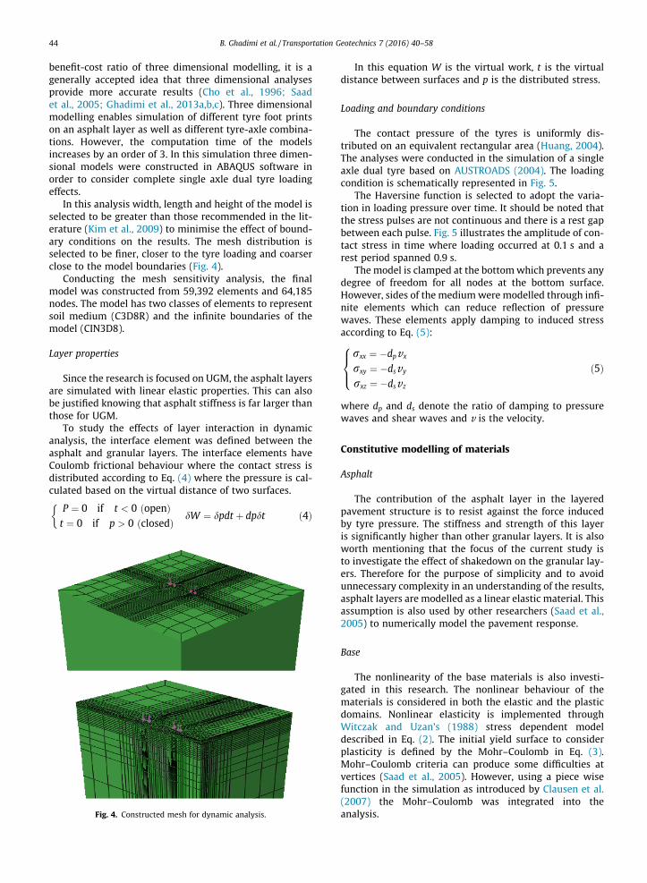
The contact pressure of the tyres is uniformly dis-tributed on an equivalent rectangular area (Huang, 2004).The analyses were conducted in the simulation of a singleaxle dual tyre based on AUSTROADS (2004). The loadingcondition is schematically represented in Fig. 5.
The Haversine function is selected to adopt the varia-tion in loading pressure over time. It should be noted thatthe stress pulses are not continuous and there is a rest gapbetween each pulse. Fig. 5 illustrates the amplitude of con-tact stress in time where loading occurred at 0.1 s and arest period spanned 0.9 s.
The model is clamped at the bottomwhich prevents anydegree of freedom for all nodes at the bottom surface.However, sides of the mediumwere modelled through infi-nite elements which can reduce reflection of pressurewaves. These elements apply damping to induced stressaccording to Eq. (5):
rxx ¼ �dpvx
rxy ¼ �dsvy
rxz ¼ �dsvz
8><>: ð5Þ
where dp and ds denote the ratio of damping to pressurewaves and shear waves and v is the velocity.
Constitutive modelling of materials
Asphalt
The contribution of the asphalt layer in the layeredpavement structure is to resist against the force inducedby tyre pressure. The stiffness and strength of this layeris significantly higher than other granular layers. It is alsoworth mentioning that the focus of the current study isto investigate the effect of shakedown on the granular lay-ers. Therefore for the purpose of simplicity and to avoidunnecessary complexity in an understanding of the results,asphalt layers are modelled as a linear elastic material. Thisassumption is also used by other researchers (Saad et al.,2005) to numerically model the pavement response.
Base
The nonlinearity of the base materials is also investi-gated in this research. The nonlinear behaviour of thematerials is considered in both the elastic and the plasticdomains. Nonlinear elasticity is implemented throughWitczak and Uzan’s (1988) stress dependent modeldescribed in Eq. (2). The initial yield surface to considerplasticity is defined by the Mohr–Coulomb in Eq. (3).Mohr–Coulomb criteria can produce some difficulties atvertices (Saad et al., 2005). However, using a piece wisefunction in the simulation as introduced by Clausen et al.(2007) the Mohr–Coulomb was integrated into theanalysis.
Fig. 5. Single axle dual tyre loading and Haversine pulses in time.
B. Ghadimi et al. / Transportation Geotechnics 7 (2016) 40–58 45
Shakedown behaviour of the material to simulate theUGM is shown in Fig. 2. When loading is applied threecases of stress field occurs as follows:
L2 6gðrk
ijÞ > L1 ! epijðtÞ ¼ f 1ðNÞepijð0Þgðrk
ijÞ 6 L1 ! epijðtÞ ¼ f 2ðNÞepijð0Þgðrk
ijÞ < L2 ! epijðtÞ ¼ f 3ðNÞepijð0Þ
8>><>>: ð6Þ
In this equation N is the number of load cycles and f1, f2and f3 are the experimentally indicated function of N. L1, L2and L3 are limits applied to stress fields indicated as g (r).Superscript k indicates the number of increments and sub-script i and j are indicators of the co-ordinates. In thisequation ep(0) is the initially induced plastic strain.
Without considering the effects of shakedown, plasticstrain is solely determined by the stress field as a functionof the loading magnitude. In repetitive constant loading,the stress field induced in each cycle does not vary signif-icantly and almost constant values of plastic strain are pro-duced in each of the cycles. However, if the stress fieldsatisfies the shakedown conditions (determined by L limitsin Eq. (6) the behaviour of the material gradually movesfrom elastoplastic to purely elastic (hypothetically whenthe number of cycles tends to infinity). This case is mathe-matically presented in Eq. (7):
rN ¼ CNeN
if N ¼ 1 ! rN ¼ ðCNÞepðeNÞep
if N ! 1 ! rN ¼ ðCNÞeðeNÞe( ð7Þ
where N is the number of cycles and C is the material stiff-ness matrix. Superscript e indicates elastic behaviourwhilst superscript ep indicates elastoplastic behaviour.
Eq. (6) can be differentiated in terms of time as follows:
@ep
@t¼ @f ðNÞ
@Nep0 ð8Þ
And from Eq. (7) it can be written
if N ¼ 1 ! @f ið1Þ@N ¼ 1
if N ! 1 ! @f iðNÞ@N ¼ 0
(ð9Þ
Substituting Eqs. (6) and (7) into (9) the material stiff-ness matrix can be modified as follows:
rN ¼ @f ðNÞ@N
� �ðCNÞepðeNÞep þ 1� @f ðNÞ
@N
� �ðCNÞeðeNÞe ð10Þ
The change of behaviour according to the number of theloading cycles can be simulated through Eq. (10).
Subgrade
The subgrade of flexible pavements is usually con-structed from lower quality materials. The subgrade maybe variable from clayey soil to fine sand. The currentMohr–Coulomb elastoplastic model is applied to simulatethe behaviour of soil in the subgrade layers. The soil prop-erties are selected to represent medium quality subgrade.In this layer the shakedown effects are not considered.The numbers of static simulations indicates that stresspassed from the base layer to the subgrade will fall belowthe elastic limit of the shakedown and therefore the inclu-sion of a subroutine will only increase computation time.
Effect of dynamic analysis
Static analysis vs dynamic
The first step of the analysis was to verify the simula-tion in the nonlinear elastic domain for static loading. Sta-tic analysis also helps to understand the effect of dynamicloading more inclusively. The nonlinear elastic constitutivemodel was implemented in the same approach introducedby Kim et al. (2009). The same model was then recon-structed to verify the developed UMAT for nonlinear elasticassessment. The model used an axisymmetric mediumwith linear asphalt layer and a nonlinear base layer. Theproperties of the nonlinear materials were consideredthrough the Witczak and Uzan (1988) stress dependentmodel where K1 = 4.1 MPa, k2 = 0.64 and k3 = 0.065.
The results of four critical responses for the flexiblepavement calculated in the current study were then
46 B. Ghadimi et al. / Transportation Geotechnics 7 (2016) 40–58
compared by the responses reported by Kim et al. (2009),and are presented in Table 1.
As it can be seen, the results of the simulation in thecurrent study are very similar to those reported by Kimet al. (2009).
In the next part of the analysis, the three dimensionalmodel described in the Section Geometric properties ofthe model was subjected to both static and dynamic load-ing as stated in Section Loading and boundary conditions.In this step, the weight of the soil was considered. Themodelled soil body had initial at rest stress before beingsubjected to the tyre pressure.
For this analysis material properties are listed in Table 2.The granular base is simulated to reflect nonlinear elastic(Witczak and Uzan, 1988) and also plastic Mohr–Coulombresponses. A 10% Rayleigh damping was included to reducethe resonance effects in the modelled area. The density ofthe materials used were selected according to typicalmaterials detailed in AUSTROADS (2004) specifications.
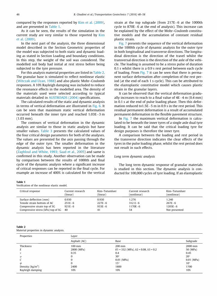
The calculated results of the static and dynamic analysisin terms of vertical deformation are illustrated in Fig. 6. Itcan be seen that maximum static vertical deformationoccurred beneath the inner tyre and reached 1.03E�3 m(1.03 mm).
The contours of vertical deformation in the dynamicanalysis are similar to those in static analysis but havesmaller values. Table 3 presents the calculated values ofthe four critical design parameters for both of the analyses.The values are presented for the axis passing through theedge of the outer tyre. The smaller deformation in thedynamic analysis has been reported in the literature(Zaghloul and White, 1993; Saad et al., 2005) and same isconfirmed in this study. Another observation can be madeby comparison between the results of 1000th and finalcycle of the dynamic analysis where a significant increaseof critical responses can be reported in the final cycle. Forexample an increase of 400% is calculated for the vertical
Table 1Verification of the nonlinear elastic model.
Critical response Current research(linear)
Kim–Tutumlu(linear)
Surface deflection (mm) 0.930 0.930Tensile strain bottom of AC 251E�6 227E�6Compressive strain top of SG 921E�6 933E�6Compressive stress (kPa) top of SG 40 41
Table 2Material properties in dynamic analysis.
Properties Layer
Asphalt (AC)
Thickness 100 mmE 2800 (MPa)m 0.35u 0C 0w 0Density (kg/m3) 2400Rayleigh damping 10%
strain at the top subgrade (from 217E�6 at the 1000thcycle to 870E�6 at the end of analysis). This increase canbe explained by the effect of the Mohr–Coulomb constitu-tive models and the accumulation of constant residualplastic strain.
Fig. 7 presents the sequence of the vertical deformationin the 1000th cycle of dynamic analysis for the outer tyrein both longitudinal and transverse directions. The longitu-dinal direction is the direction of the travel whilst thetransversal direction is the direction of the axle of the vehi-cle. The loading is assumed to be a stress pulse of duration0.1 s whilst there is a 0.9 s rest period between each cycleof loading. From Fig. 7 it can be seen that there is perma-nent surface deformation after completion of the rest per-iod (at the end of each 1 s cycle). This can be attributed tothe elastoplastic constitutive model which causes plasticstrain in the granular layers.
It can be observed that the vertical deformation gradu-ally increases to reach to a final value of 4E�4 m (0.4 mm)in 0.1 s at the end of pulse loading phase. Then this defor-mation reduced to1.5E�5 m in 0.9 s in the rest period. Thisresidual permanent deformation is a result of accumulatedpermanent deformation in the flexible pavement structure.
In Fig. 7 the maximum vertical deformation is calcu-lated to be beneath the inner tyres of a single axle dual tyreloading. It can be said that the critical loading tyre fordesign purposes is therefore the inner tyre.
A comparison between the loading and rest period inthe transverse direction indicates the clear effects of thetyres in the pulse loading phase, whilst the rest period doesnot result in such effects.
Long term dynamic analysis
The long term dynamic response of granular materialsis studied in this section. The dynamic analysis is con-ducted for 100,000 cycles of tyre loading. If an elastoplastic
er Current research(nonlinear)
Kim–Tutumluer(nonlinear)
1.276 1.240312 E�6 267E�61170E�6 1203E�654 Not presented
Base Subgrade
200 mm 2000 mmK1 = 332 (MPa), k2 = 0.08, k3 = 0.2 50 (MPa)0.4 0.4530� 20�0.01 (MPa) 0.01 (MPa)15� 10�1800 170010% 10%
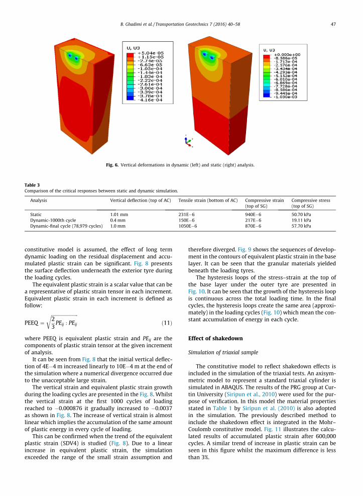
Fig. 6. Vertical deformations in dynamic (left) and static (right) analysis.
Table 3Comparison of the critical responses between static and dynamic simulation.
Analysis Vertical deflection (top of AC) Tensile strain (bottom of AC) Compressive strain(top of SG)
Compressive stress(top of SG)
Static 1.01 mm 231E�6 940E�6 50.70 kPaDynamic-1000th cycle 0.4 mm 150E�6 217E�6 19.11 kPaDynamic-final cycle (78,979 cycles) 1.0 mm 1050E�6 870E�6 57.70 kPa
B. Ghadimi et al. / Transportation Geotechnics 7 (2016) 40–58 47
constitutive model is assumed, the effect of long termdynamic loading on the residual displacement and accu-mulated plastic strain can be significant. Fig. 8 presentsthe surface deflection underneath the exterior tyre duringthe loading cycles.
The equivalent plastic strain is a scalar value that can bea representative of plastic strain tensor in each increment.Equivalent plastic strain in each increment is defined asfollow:
PEEQ ¼ffiffiffiffiffiffiffiffiffiffiffiffiffiffiffiffiffiffiffiffiffiffiffi23PEij : PEij
rð11Þ
where PEEQ is equivalent plastic strain and PEij are thecomponents of plastic strain tensor at the given incrementof analysis.
It can be seen from Fig. 8 that the initial vertical deflec-tion of 4E�4 m increased linearly to 10E�4 m at the end ofthe simulation where a numerical divergence occurred dueto the unacceptable large strain.
The vertical strain and equivalent plastic strain growthduring the loading cycles are presented in the Fig. 8. Whilstthe vertical strain at the first 1000 cycles of loadingreached to �0.000876 it gradually increased to �0.0037as shown in Fig. 8. The increase of vertical strain is almostlinear which implies the accumulation of the same amountof plastic energy in every cycle of loading.
This can be confirmed when the trend of the equivalentplastic strain (SDV4) is studied (Fig. 8). Due to a linearincrease in equivalent plastic strain, the simulationexceeded the range of the small strain assumption and
therefore diverged. Fig. 9 shows the sequences of develop-ment in the contours of equivalent plastic strain in the baselayer. It can be seen that the granular materials yieldedbeneath the loading tyres.
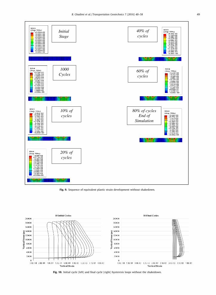
The hysteresis loops of the stress–strain at the top ofthe base layer under the outer tyre are presented inFig. 10. It can be seen that the growth of the hysteresis loopis continuous across the total loading time. In the finalcycles, the hysteresis loops create the same area (approxi-mately) in the loading cycles (Fig. 10) which mean the con-stant accumulation of energy in each cycle.
Effect of shakedown
Simulation of triaxial sample
The constitutive model to reflect shakedown effects isincluded in the simulation of the triaxial tests. An axisym-metric model to represent a standard triaxial cylinder issimulated in ABAQUS. The results of the PRG group at Cur-tin University (Siripun et al., 2010) were used for the pur-pose of verification. In this model the material propertiesstated in Table 1 by Siripun et al. (2010) is also adoptedin the simulation. The previously described method toinclude the shakedown effect is integrated in the Mohr–Coulomb constitutive model. Fig. 11 illustrates the calcu-lated results of accumulated plastic strain after 600,000cycles. A similar trend of increase in plastic strain can beseen in this figure whilst the maximum difference is lessthan 3%.
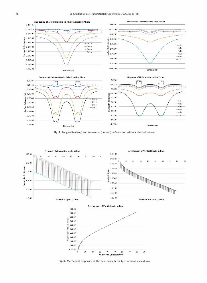
Fig. 7. Longitudinal (up) and transverse (bottom) deformation without the shakedown.
Fig. 8. Mechanical responses of the base beneath the tyre without shakedown.
48 B. Ghadimi et al. / Transportation Geotechnics 7 (2016) 40–58
1000 Cycles
Initial Stage
10% of cycles
20% of cycles
40% of cycles
60% of cycles
80% of cycles End of
Simulation
Fig. 9. Sequence of equivalent plastic strain development without shakedown.
Fig. 10. Initial cycle (left) and final cycle (right) hysteresis loops without the shakedown.
B. Ghadimi et al. / Transportation Geotechnics 7 (2016) 40–58 49
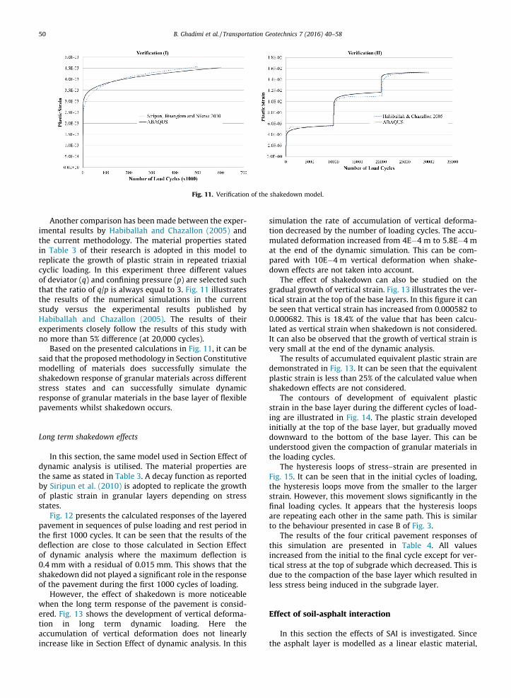
Fig. 11. Verification of the shakedown model.
50 B. Ghadimi et al. / Transportation Geotechnics 7 (2016) 40–58
Another comparison has been made between the exper-imental results by Habiballah and Chazallon (2005) andthe current methodology. The material properties statedin Table 3 of their research is adopted in this model toreplicate the growth of plastic strain in repeated triaxialcyclic loading. In this experiment three different valuesof deviator (q) and confining pressure (p) are selected suchthat the ratio of q/p is always equal to 3. Fig. 11 illustratesthe results of the numerical simulations in the currentstudy versus the experimental results published byHabiballah and Chazallon (2005). The results of theirexperiments closely follow the results of this study withno more than 5% difference (at 20,000 cycles).
Based on the presented calculations in Fig. 11, it can besaid that the proposedmethodology in Section Constitutivemodelling of materials does successfully simulate theshakedown response of granular materials across differentstress states and can successfully simulate dynamicresponse of granular materials in the base layer of flexiblepavements whilst shakedown occurs.
Long term shakedown effects
In this section, the same model used in Section Effect ofdynamic analysis is utilised. The material properties arethe same as stated in Table 3. A decay function as reportedby Siripun et al. (2010) is adopted to replicate the growthof plastic strain in granular layers depending on stressstates.
Fig. 12 presents the calculated responses of the layeredpavement in sequences of pulse loading and rest period inthe first 1000 cycles. It can be seen that the results of thedeflection are close to those calculated in Section Effectof dynamic analysis where the maximum deflection is0.4 mm with a residual of 0.015 mm. This shows that theshakedown did not played a significant role in the responseof the pavement during the first 1000 cycles of loading.
However, the effect of shakedown is more noticeablewhen the long term response of the pavement is consid-ered. Fig. 13 shows the development of vertical deforma-tion in long term dynamic loading. Here theaccumulation of vertical deformation does not linearlyincrease like in Section Effect of dynamic analysis. In this
simulation the rate of accumulation of vertical deforma-tion decreased by the number of loading cycles. The accu-mulated deformation increased from 4E�4 m to 5.8E�4 mat the end of the dynamic simulation. This can be com-pared with 10E�4 m vertical deformation when shake-down effects are not taken into account.
The effect of shakedown can also be studied on thegradual growth of vertical strain. Fig. 13 illustrates the ver-tical strain at the top of the base layers. In this figure it canbe seen that vertical strain has increased from 0.000582 to0.000682. This is 18.4% of the value that has been calcu-lated as vertical strain when shakedown is not considered.It can also be observed that the growth of vertical strain isvery small at the end of the dynamic analysis.
The results of accumulated equivalent plastic strain aredemonstrated in Fig. 13. It can be seen that the equivalentplastic strain is less than 25% of the calculated value whenshakedown effects are not considered.
The contours of development of equivalent plasticstrain in the base layer during the different cycles of load-ing are illustrated in Fig. 14. The plastic strain developedinitially at the top of the base layer, but gradually moveddownward to the bottom of the base layer. This can beunderstood given the compaction of granular materials inthe loading cycles.
The hysteresis loops of stress–strain are presented inFig. 15. It can be seen that in the initial cycles of loading,the hysteresis loops move from the smaller to the largerstrain. However, this movement slows significantly in thefinal loading cycles. It appears that the hysteresis loopsare repeating each other in the same path. This is similarto the behaviour presented in case B of Fig. 3.
The results of the four critical pavement responses ofthis simulation are presented in Table 4. All valuesincreased from the initial to the final cycle except for ver-tical stress at the top of subgrade which decreased. This isdue to the compaction of the base layer which resulted inless stress being induced in the subgrade layer.
Effect of soil-asphalt interaction
In this section the effects of SAI is investigated. Sincethe asphalt layer is modelled as a linear elastic material,
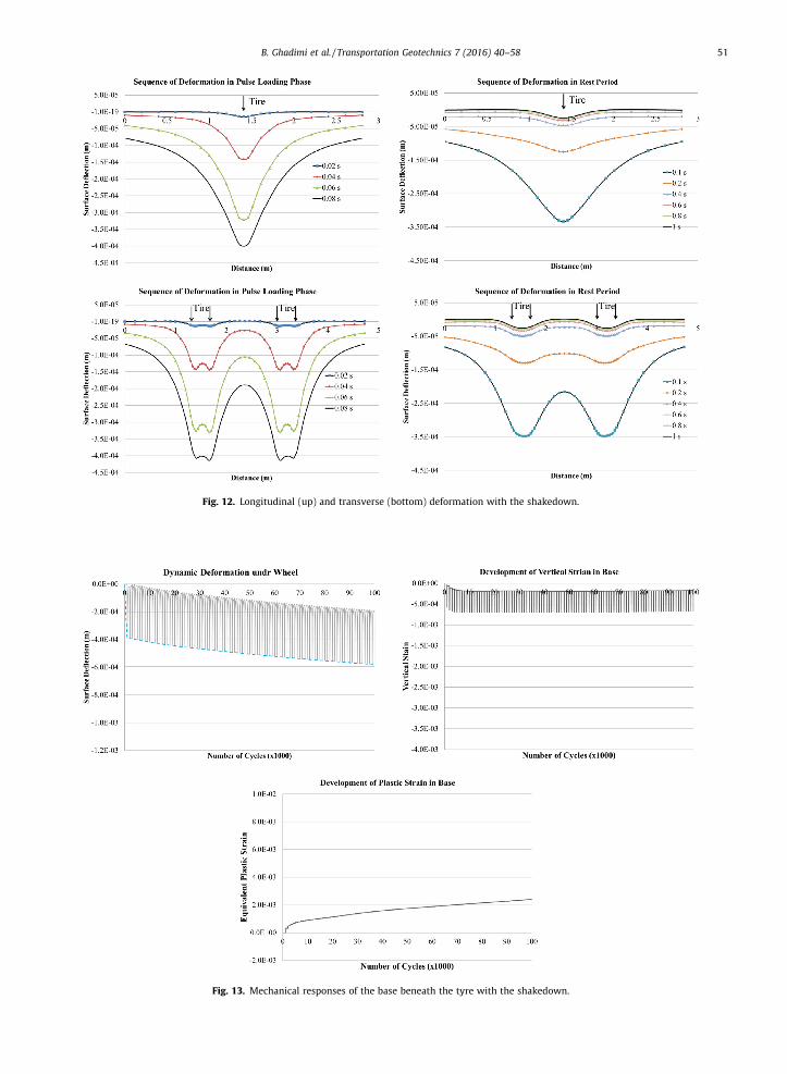
Fig. 12. Longitudinal (up) and transverse (bottom) deformation with the shakedown.
Fig. 13. Mechanical responses of the base beneath the tyre with the shakedown.
B. Ghadimi et al. / Transportation Geotechnics 7 (2016) 40–58 51

Initial Stage
1000 Cycles
20% of cycles
10% of cycles
80% of cycles
60% of cycles
40% of cycles
End of cycles
Fig. 14. Sequence of equivalent plastic strain development with shakedown.
Fig. 15. Initial cycles (left) and final cycles (right) hysteresis loops with shakedown.
52 B. Ghadimi et al. / Transportation Geotechnics 7 (2016) 40–58
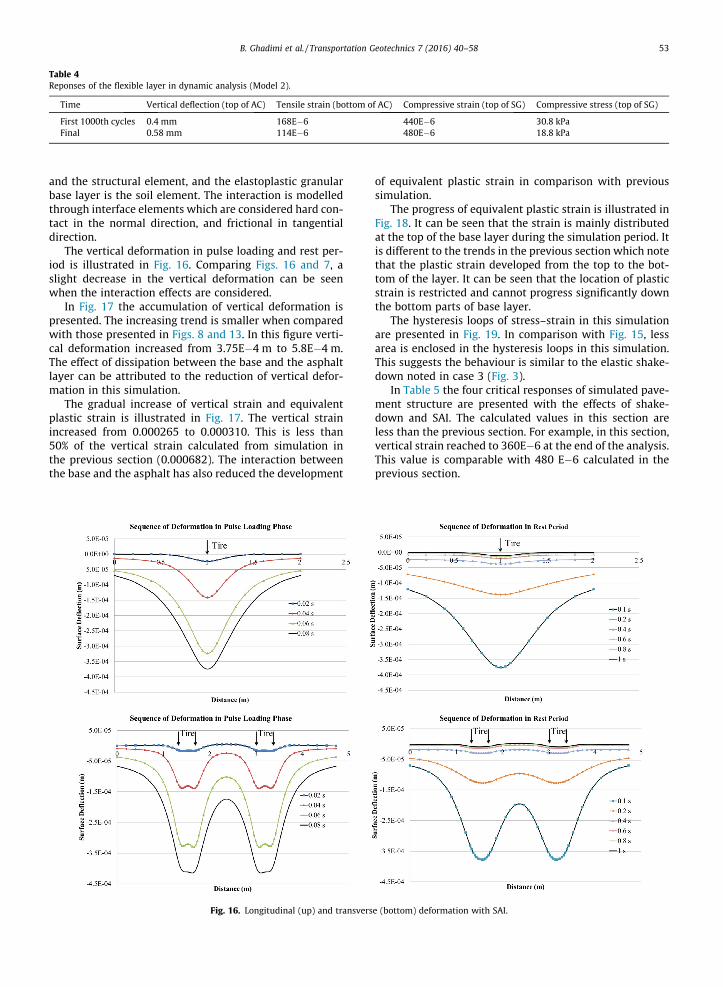
Table 4Reponses of the flexible layer in dynamic analysis (Model 2).
Time Vertical deflection (top of AC) Tensile strain (bottom of AC) Compressive strain (top of SG) Compressive stress (top of SG)
First 1000th cycles 0.4 mm 168E�6 440E�6 30.8 kPaFinal 0.58 mm 114E�6 480E�6 18.8 kPa
B. Ghadimi et al. / Transportation Geotechnics 7 (2016) 40–58 53
and the structural element, and the elastoplastic granularbase layer is the soil element. The interaction is modelledthrough interface elements which are considered hard con-tact in the normal direction, and frictional in tangentialdirection.
The vertical deformation in pulse loading and rest per-iod is illustrated in Fig. 16. Comparing Figs. 16 and 7, aslight decrease in the vertical deformation can be seenwhen the interaction effects are considered.
In Fig. 17 the accumulation of vertical deformation ispresented. The increasing trend is smaller when comparedwith those presented in Figs. 8 and 13. In this figure verti-cal deformation increased from 3.75E�4 m to 5.8E�4 m.The effect of dissipation between the base and the asphaltlayer can be attributed to the reduction of vertical defor-mation in this simulation.
The gradual increase of vertical strain and equivalentplastic strain is illustrated in Fig. 17. The vertical strainincreased from 0.000265 to 0.000310. This is less than50% of the vertical strain calculated from simulation inthe previous section (0.000682). The interaction betweenthe base and the asphalt has also reduced the development
Fig. 16. Longitudinal (up) and transvers
of equivalent plastic strain in comparison with previoussimulation.
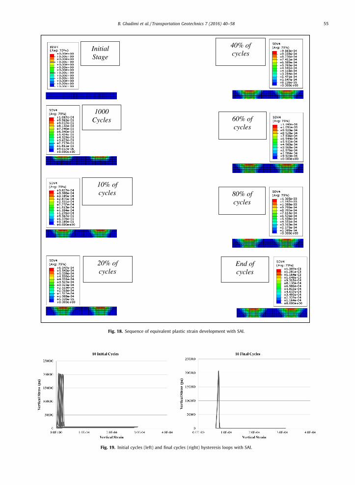
The progress of equivalent plastic strain is illustrated inFig. 18. It can be seen that the strain is mainly distributedat the top of the base layer during the simulation period. Itis different to the trends in the previous section which notethat the plastic strain developed from the top to the bot-tom of the layer. It can be seen that the location of plasticstrain is restricted and cannot progress significantly downthe bottom parts of base layer.
The hysteresis loops of stress–strain in this simulationare presented in Fig. 19. In comparison with Fig. 15, lessarea is enclosed in the hysteresis loops in this simulation.This suggests the behaviour is similar to the elastic shake-down noted in case 3 (Fig. 3).
In Table 5 the four critical responses of simulated pave-ment structure are presented with the effects of shake-down and SAI. The calculated values in this section areless than the previous section. For example, in this section,vertical strain reached to 360E�6 at the end of the analysis.This value is comparable with 480 E�6 calculated in theprevious section.
e (bottom) deformation with SAI.
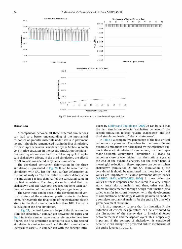
Fig. 17. Mechanical responses of the base beneath tyre with SAI.
54 B. Ghadimi et al. / Transportation Geotechnics 7 (2016) 40–58
Discussion
A comparison between all three different simulationscan lead to a better understanding of the mechanicalresponses of granular materials under stress in pavementlayers. It should be remembered that in the first simulation,the base layer behaviour ismodelled by theMohr–Coulombconstitutive equation. In the second simulation the Mohr–Coulomb equation ismodified in each loading cycle to repli-cate shakedown effects. In the third simulation, the effectsof SAI are also considered in dynamic simulation.
The developed permanent deformation in the threesimulations is presented in Fig. 20. It can be seen that thesimulation with SAI, has the least surface deformation atthe end of analysis. The final value of surface deformationin simulation 3 is less than half of the calculated value inthe first simulation. Therefore, it can be stated that theshakedown and SAI have both reduced the long term sur-face deformation of the pavement layers significantly.
The same trend can be seen in the development of ver-tical strain and the equivalent plastic strain in the baselayer. For example the final value of the equivalent plasticstrain in the third simulation is less than 10% of what iscalculated in the first simulation.
In Fig. 21, the final hysteresis loops of the three simula-tions are presented. A comparison between this figure andFig. 3 indicates similar responses. In reference to these twofigures, the first simulation is similar to case A, the secondsimulation is similar to case B and the third simulation isidentical to case C. In comparison with the concept intro-
duced by Collins and Boulbibane (2000), it can be said thatthe first simulation reflects ‘‘ratcheting behaviour”, thesecond simulation reflects ‘‘plastic shakedown” and thethird simulation leads to ‘‘elastic shakedown”.
In Table 6 a comparative percentage of the four criticalresponses are presented. The values for the three differentdynamic simulations are normalised by the calculated val-ues in the static simulation. It can be seen, that the simpleMohr–Coulomb assumption (simulation 1) leads toresponses close or even higher than the static analysis atthe end of the dynamic analysis. On the other hand, ameaningful reduction in these responses can be seen whenshakedown (simulation 2) and SAI (simulation 3) areconsidered. It should be mentioned that these four criticalvalues are important in flexible pavement design codes(AASHTO, 1993; AUSTROADS, 2004). In these codes, thevalues of these responses are calculated in a very simplestatic linear elastic analysis and then, other complexeffects are implemented through design trial function (alsocalled transfer function). However, with the developmentof computational technology it will be possible to conducta complete mechanical analysis for the entire life time of agiven pavement structure.
It is also important to note that in simulation 3, thereduction of critical design values can be attributed tothe dissipation of the energy due to interfacial forcesbetween the base and the asphalt layers. This is especiallyimportant if the concept of shakedown is consideredbecause it can change the predicted failure mechanism ofthe entire layered structure.
Initial Stage
1000 Cycles
10% of cycles
20% of cycles
40% of cycles
60% of cycles
80% of cycles
End of cycles
Fig. 18. Sequence of equivalent plastic strain development with SAI.
Fig. 19. Initial cycles (left) and final cycles (right) hysteresis loops with SAI.
B. Ghadimi et al. / Transportation Geotechnics 7 (2016) 40–58 55
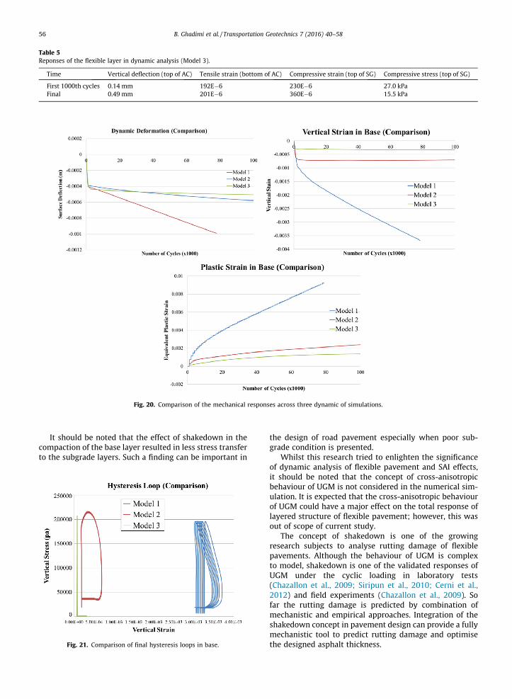
Table 5Reponses of the flexible layer in dynamic analysis (Model 3).
Time Vertical deflection (top of AC) Tensile strain (bottom of AC) Compressive strain (top of SG) Compressive stress (top of SG)
First 1000th cycles 0.14 mm 192E�6 230E�6 27.0 kPaFinal 0.49 mm 201E�6 360E�6 15.5 kPa
Fig. 20. Comparison of the mechanical responses across three dynamic of simulations.
56 B. Ghadimi et al. / Transportation Geotechnics 7 (2016) 40–58
It should be noted that the effect of shakedown in thecompaction of the base layer resulted in less stress transferto the subgrade layers. Such a finding can be important in
Fig. 21. Comparison of final hysteresis loops in base.
the design of road pavement especially when poor sub-grade condition is presented.
Whilst this research tried to enlighten the significanceof dynamic analysis of flexible pavement and SAI effects,it should be noted that the concept of cross-anisotropicbehaviour of UGM is not considered in the numerical sim-ulation. It is expected that the cross-anisotropic behaviourof UGM could have a major effect on the total response oflayered structure of flexible pavement; however, this wasout of scope of current study.
The concept of shakedown is one of the growingresearch subjects to analyse rutting damage of flexiblepavements. Although the behaviour of UGM is complexto model, shakedown is one of the validated responses ofUGM under the cyclic loading in laboratory tests(Chazallon et al., 2009; Siripun et al., 2010; Cerni et al.,2012) and field experiments (Chazallon et al., 2009). Sofar the rutting damage is predicted by combination ofmechanistic and empirical approaches. Integration of theshakedown concept in pavement design can provide a fullymechanistic tool to predict rutting damage and optimisethe designed asphalt thickness.
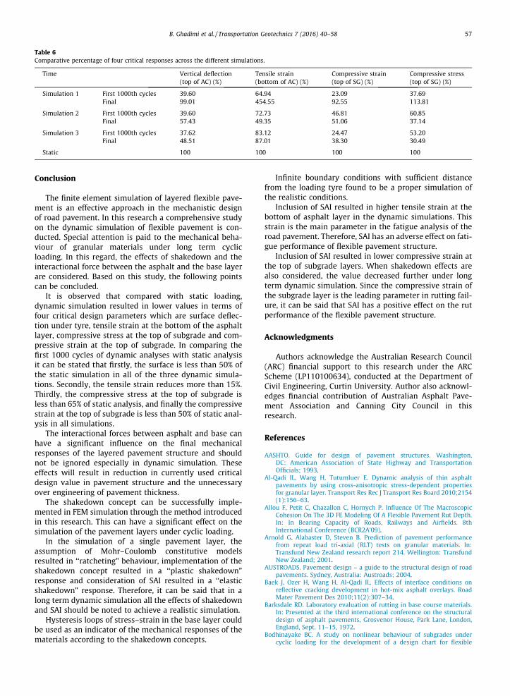
Table 6Comparative percentage of four critical responses across the different simulations.
Time Vertical deflection(top of AC) (%)
Tensile strain(bottom of AC) (%)
Compressive strain(top of SG) (%)
Compressive stress(top of SG) (%)
Simulation 1 First 1000th cycles 39.60 64.94 23.09 37.69Final 99.01 454.55 92.55 113.81
Simulation 2 First 1000th cycles 39.60 72.73 46.81 60.85Final 57.43 49.35 51.06 37.14
Simulation 3 First 1000th cycles 37.62 83.12 24.47 53.20Final 48.51 87.01 38.30 30.49
Static 100 100 100 100
B. Ghadimi et al. / Transportation Geotechnics 7 (2016) 40–58 57
Conclusion
The finite element simulation of layered flexible pave-ment is an effective approach in the mechanistic designof road pavement. In this research a comprehensive studyon the dynamic simulation of flexible pavement is con-ducted. Special attention is paid to the mechanical beha-viour of granular materials under long term cyclicloading. In this regard, the effects of shakedown and theinteractional force between the asphalt and the base layerare considered. Based on this study, the following pointscan be concluded.
It is observed that compared with static loading,dynamic simulation resulted in lower values in terms offour critical design parameters which are surface deflec-tion under tyre, tensile strain at the bottom of the asphaltlayer, compressive stress at the top of subgrade and com-pressive strain at the top of subgrade. In comparing thefirst 1000 cycles of dynamic analyses with static analysisit can be stated that firstly, the surface is less than 50% ofthe static simulation in all of the three dynamic simula-tions. Secondly, the tensile strain reduces more than 15%.Thirdly, the compressive stress at the top of subgrade isless than 65% of static analysis, and finally the compressivestrain at the top of subgrade is less than 50% of static anal-ysis in all simulations.
The interactional forces between asphalt and base canhave a significant influence on the final mechanicalresponses of the layered pavement structure and shouldnot be ignored especially in dynamic simulation. Theseeffects will result in reduction in currently used criticaldesign value in pavement structure and the unnecessaryover engineering of pavement thickness.
The shakedown concept can be successfully imple-mented in FEM simulation through the method introducedin this research. This can have a significant effect on thesimulation of the pavement layers under cyclic loading.
In the simulation of a single pavement layer, theassumption of Mohr–Coulomb constitutive modelsresulted in ‘‘ratcheting” behaviour, implementation of theshakedown concept resulted in a ‘‘plastic shakedown”response and consideration of SAI resulted in a ‘‘elasticshakedown” response. Therefore, it can be said that in along term dynamic simulation all the effects of shakedownand SAI should be noted to achieve a realistic simulation.
Hysteresis loops of stress–strain in the base layer couldbe used as an indicator of the mechanical responses of thematerials according to the shakedown concepts.
Infinite boundary conditions with sufficient distancefrom the loading tyre found to be a proper simulation ofthe realistic conditions.
Inclusion of SAI resulted in higher tensile strain at thebottom of asphalt layer in the dynamic simulations. Thisstrain is the main parameter in the fatigue analysis of theroad pavement. Therefore, SAI has an adverse effect on fati-gue performance of flexible pavement structure.
Inclusion of SAI resulted in lower compressive strain atthe top of subgrade layers. When shakedown effects arealso considered, the value decreased further under longterm dynamic simulation. Since the compressive strain ofthe subgrade layer is the leading parameter in rutting fail-ure, it can be said that SAI has a positive effect on the rutperformance of the flexible pavement structure.
Acknowledgments
Authors acknowledge the Australian Research Council(ARC) financial support to this research under the ARCScheme (LP110100634), conducted at the Department ofCivil Engineering, Curtin University. Author also acknowl-edges financial contribution of Australian Asphalt Pave-ment Association and Canning City Council in thisresearch.
References
AASHTO. Guide for design of pavement structures. Washington,DC: American Association of State Highway and TransportationOfficials; 1993.
Al-Qadi IL, Wang H, Tutumluer E. Dynamic analysis of thin asphaltpavements by using cross-anisotropic stress-dependent propertiesfor granular layer. Transport Res Rec J Transport Res Board 2010;2154(1):156–63.
Allou F, Petit C, Chazallon C, Hornych P. Influence Of The MacroscopicCohesion On The 3D FE Modeling Of A Flexible Pavement Rut Depth.In: In Bearing Capacity of Roads, Railways and Airfields. 8thInternational Conference (BCR2A’09).
Arnold G, Alabaster D, Steven B. Prediction of pavement performancefrom repeat load tri-axial (RLT) tests on granular materials. In:Transfund New Zealand research report 214. Wellington: TransfundNew Zealand; 2001.
AUSTROADS. Pavement design – a guide to the structural design of roadpavements. Sydney, Australia: Austroads; 2004.
Baek J, Ozer H, Wang H, Al-Qadi IL. Effects of interface conditions onreflective cracking development in hot-mix asphalt overlays. RoadMater Pavement Des 2010;11(2):307–34.
Barksdale RD. Laboratory evaluation of rutting in base course materials.In: Presented at the third international conference on the structuraldesign of asphalt pavements, Grosvenor House, Park Lane, London,England, Sept. 11–15, 1972.
Bodhinayake BC. A study on nonlinear behaviour of subgrades undercyclic loading for the development of a design chart for flexible
58 B. Ghadimi et al. / Transportation Geotechnics 7 (2016) 40–58
pavements [Ph.D. dessertation]. University of Wollongong ThesisCollection; 1979.
Boulbibane M, Weichert D. Application of shakedown theory to soils withnon associated flow rules. Mech Res Commun 1997;24(5):513–9.
Cerni G, Cardone F, Virgili A, Camilli S. Characterisation of permanentdeformation behaviour of unbound granular materials underrepeated triaxial loading. Constr Build Mater 2012;28(1):79–87.
Chazallon C, Allou F, Hornych P, Mouhoubi S. Finite elements modelling ofthe long-term behaviour of a full-scale flexible pavement with theshakedown theory. Int J Numer Anal Meth Geomech 2009;33(1):45–70.
Cho YH, McCullough BF, Weissmann J. Considerations on finite-elementmethod application in pavement structural analysis. Transport ResRecord J Transport Res Board 1996;1539(1):96–101.
Clausen J, Damkilde L, Andersen L. An efficient return algorithm for non-associated plasticity with linear yield criteria in principal stress space.Comput Struct 2007;85(23):1795–807.
Collins I, Boulbibane M. Geomechanical analysis of unbound pavementsbased on shakedown theory. J Geotech Geoenviron Eng 2000;126(1):50–9.
Collins IF, Boulbibane M. The application of shakedown theory topavement design. Met Mater 1998;4(4):832–7.
Cortes D, Shin H, Santamarina J. Numerical simulation of invertedpavement systems. J Transport Eng 2012;138(12):1507–19.
Ghadimi B, Asadi H, Nikraz H, Leek C. Effects of geometrical parameters onnumerical modeling of pavement granular material. In: Airfield andhighway pavement 2013@ sustainable and efficientpavements. ASCE; 2013a. p. 1291–303.
Ghadimi B, Nega A, Nikraz H. Simulation of shakedown behavior in
pavement’s granular layer. Int J Eng Technol 2014;7:6.Ghadimi B, Nikraz H, Leek C. A comparison of different approaches in
numerical modeling of pavement granular material. Adv Mater Res2013b;273:9.
Ghadimi B, Nikraz H, Leek C, Nega A. A comparison between effects oflinear and non-linear mechanistic behaviour of materials on thelayered flexible pavement response. Adv Mater Res 2013c;723:12–21.
Habiballah T, Chazallon C. An elastoplastic model based on theshakedown concept for flexible pavements unbound granularmaterials. Int J Numer Anal Meth Geomech 2005;29(6):577–96.
Hicks RG, Monismith CL. Factors influencing the resilient response ofgranular materials. Highway Res Rec 1971;345:15–31.
Hjelmstad K, Taciroglu E. Analysis and implementation of resilientmodulus models for granular solids. J Eng Mech 2000;126(8):821–30.
Holanda ÁS, Parente Junior E, Araújo TDP, Melo LTB, Evangelista Junior F,Soares JB. Finite element modeling of flexible pavements. Belém,Pará: Iberian Latin American Congress on Computational Methods inEngineering (CILAMCE); 2006.
Huang YH. Pavement analysis and design. USA: Pearson Prentice Hall,Pearson Education Inc.; 2004.
Kim M, Tutumluer E. Modeling nonlinear, stress-dependent pavementfoundation behavior using a general-purpose finite element program.Geotech Special Publ 2006;154:29.
Kim M, Tutumluer E. Validation of a three-dimensional finite elementmodel using airfield pavement multiple wheel load responses. RoadMater Pavement Des 2010;11(2):387–408.
Kim M, Tutumluer E, Kwon J. Nonlinear pavement foundation modelingfor three-dimensional finite-element analysis of flexible pavements.Int J Geomech 2009;9:195.
Korkiala-Tanttu L, Laaksonen R, Törnqvist J. Effect of spring and overloadto the rutting of a low-volume road. Helsinki: HVS-Nordic-research,Finnish Road Administration; 2003. Finnra Reports 22/2003.
Lee J, Kim J, Kang B. Normalized resilient modulus model for subbase andsubgrade based on stress-dependent modulus degradation. JTransport Eng 2009;135(9):600–10.
Little PH. The design of unsurfaced roads using geosynthetics Ph.D.dessertation. University of Nottingham; 1993.
Melan E. Zur plastizität des räumlichen kontinuums. Arch Appl Mech1938;9(2):116–26.
Mishra D, Tutumluer E. Aggregate physical properties affecting modulusand deformation characteristics of unsurfaced pavements. J Mater CivEng 2012;24(9):1144–52.
Myers LA, Roque R, Birgisson B. Use of two-dimensional finite elementanalysis to represent bending response of asphalt pavementstructures. Int J Pavement Eng 2001;2(3):201–14.
Ozer H, Al-Qadi IL, Wang H, Leng Z. Characterisation of interface bondingbetween hot-mix asphalt overlay and concrete pavements: modellingand in-situ response to accelerated loading. Int J Pavement Eng2012;13(2):181–96.
Pan G, Okada H, Atluri S. Nonlinear transient dynamic analysis of soil-pavement interaction under moving load: a coupled BEM-FEMapproach. Eng Anal Boundary Elem 1994;14(1):99–112.
Pidwerbesky BD. Fundamental behaviour of unbound granularpavements subjected to various loading conditions and acceleratedtrafficking Ph.D. dessertation. Christchurch, New Zealand: Universityof Canterbury; 1996.
Saad B, Mitri H, Poorooshasb H. Three-dimensional dynamic analysis offlexible conventional pavement foundation. J Transport Eng 2005;131(6):460–9.
Seed HB, Chan C, Lee C. Resilience characteristics of subgrade soils andtheir relation to fatigue failures in asphalt pavements, 1962.
Sharp R. Pavement design based on shakedown analysis. In:Transportation research record 1022 1985;vol. 1985. Washington,DC: TRB, National Research Council; 1985. p. 99–107.
Sharp RW, Booker JR. Shakedown of pavements under moving surfaceloads. J Transport Eng 1984;110:1.
Shen W, Kirkner DJ. Non-linear finite-element analysis to predictpermanent deformations in pavement structures under movingloads. Int J Pavement Eng 2001;2(3):187–99.
Siripun K, Jitsangiam P, Nikraz H. Permanent deformation behaviour andmodel of crushed rock base. Aust J Civil Eng 2010;8(1):41.
Taciroglu E, Hjelmstad K. Simple nonlinear model for elastic response ofcohesionless granular materials. J Eng Mech 2002;128(9):969–78.
Uddin W, Pan Z. Finite-element analysis of flexible pavements withdiscontinuities. Transportation congress. Civil engineers – key to theWorld’s infrastructure 1995;vols. 1 and 2, 1995. p. 410–23.
Uddin W, Zhang D, Fernandez F. Finite element simulation of pavementdiscontinuities and dynamic load response. Transportation researchrecord 1448 TRB 1994;1994. Washington (DC): National ResearchCouncil; 1994. p. 100–6.
Uzan J. Characterization of granular material. In: Transportation researchrecord (1022). Washington, DC: Transportation Research Board; 1985.p. 52–9.
Witczak MW, Uzan J. The universal airport pavement design system. In:Report I of V: granular material characterization. College Park,MD: Department of Civil Engineering, University of Maryland; 1988.
Yu H-S. Plasticity and geotechnics. Springer; 2006.Yu H-S, Hossain MZ. Lower bound shakedown analysis of layered
pavements using discontinuous stress fields. Comput Method ApplMech Eng 1998;167:209–22.
Zaghloul S, White T. Use of a three-dimensional, dynamic finite elementprogram for analysis of flexible pavement. Transp Res Rec1993;1388:60–9.
Zarka J, Casier J. Elastic plastic response of structure to cyclic loading:practical rules. Mech Today 1979;6:93–198.