dynaflow model 390 control valve - cvi solutions€¦ · · 2016-10-11390 control valve 4 table 4...
TRANSCRIPT

Dyna-Flo Control Valve Services Ltd.Edmonton, Alberta, CANADA Website: www.dynaflo.com
Phone: 780 • 469 • 4000Toll Free: 1 • 866 • 396 • 2356 Fax: 780 • 469 • 4035
Technical Sales Bulletin April 2012 P-390B0412A
Model390 Control Valve
1
Features
High Quality ConstructionDyna-Flo uses only materials that have been proven to provide superior, trouble free performance. All materials comply with ASME and ASTM specifi cations.
VersatilityA wide range of trim options including Anti-Cavitation and Low-Noise make the 390 a highly versatile control valve.
Field Service FriendlyNo special tools are required to change or inspect trim. Top access makes in-line service easy.
Industrial High QualityExternal CoatingsOur standard industrial high qualityexternal coatings provide long lasting resistance to the harshest environments.
Pressure Drop CapabilitiesThe Model 390 can shut off against inletpressure equal to ASME B16.34 rating.
Sour Gas Service CapabilityThe Model 390 can be constructed out ofmaterials that comply with the recommen-dations of the National Association ofCorrosion Engineers (NACE) MR-0175.
Shut Off Classifi cationSeat leakage options range from ASME/FCI class II to class V.
Plug DesignStandard balanced plug design allows the use of smaller actuators.
Environmentally FriendlyAvailable with low emission live loaded packing.
The Model 390 control valve (Figure 1) is a heavyduty globe style control valve. This valve is used in all kinds of demanding applications, including oil and gas production and chemical process. Metal seats are used for increased seat life.
Model 390 valves are cage guided, single port valvesthat can be used in either snap on/off acting or throttling applications of either liquids or gases. A bolted bonnet is standard and a typical actuator is a Dyna-Flo DFC or DFOmodel linear actuator.
Figure 1 Model 390 Control Valve with DFC Actuator

Dyna-Flo Control Valve Services Ltd.Edmonton, Alberta, CANADA Website: www.dynaflo.com
Phone: 780 • 469 • 4000Toll Free: 1 • 866 • 396 • 2356 Fax: 780 • 469 • 4035
Technical Sales Bulletin April 2012 P-390B0412A
Model390 Control Valve
2
Specifi cations
Confi gurationsSee Table 1.
Consult your Dyna-Flo sales offi ce for other availableconfi gurations.
Sizes and Connection StylesModel: 390Size: 2”, 3”, 4”, and 6”Rating: ASME 900 or 1500Connections: RF / RTJ (for other connection styles consult Dyna-Flo).
Maximum Inlet Temperatures and PressuresConsistent with ASME class rating as per ASME B16.34, unless limited by either material, pressureor temperature limitations.
Maximum Pressure DropsSame as maximum inlet pressure unless otherwiserated by specifi c trim construction. For Actuator andValve assembly shut off pressure drops see Tables11 and 12. For trim pressure/temperature ratings see Figure 5.
Standard Seat Leakage Classifi cationsSee Table 1.
Dimensions Valve and Actuator Assembly Dimensions See Table 3 & 4, and Figure 2.
Approximate Valve Body and Actuator WeightsSee Table 2.
Valve Body to Bonnet BoltingStandard service body to bonnet:SA193-B7 StudsSA-194-2H Nuts
For NACE-2002SA-193-B7M StudsSA-194-2HM Nuts
Characteristics- Equal Percentage (Standard)- Modifi ed Equal Percentage (Same cage as Equal Percentage, different travel)- Linear- Low-Noise 3- Anti-Cavitation 2-Stage- Anti-Cavitation 3-Stage
Packing TypeThe standard packing is PTFE V-Ring. Liveloaded low emission, graphite and other packing arrangements are also available.
Valve Sizing Coeffi cientsSee Table 6, 7, 8, and 9.
Valve Travel and Yoke Boss SizesSee Table 13.
Trim MaterialsSee Table 14.
Valve Bolting Temperature Limitations
See Table 15.
Valve Parts List, Material and Temperature LimitationsSee Table 10, 14, 15, and 16.See Figure 5 and 6.
Dyna-Flo Control Valve Services Ltd.Edmonton, Alberta, CANADA Website: www.dynaflo.com
Phone: 780 • 469 • 4000Toll Free: 1 • 866 • 396 • 2356 Fax: 780 • 469 • 4035
Technical Sales Bulletin April 2012 P-390B0412A
Model390 Control Valve
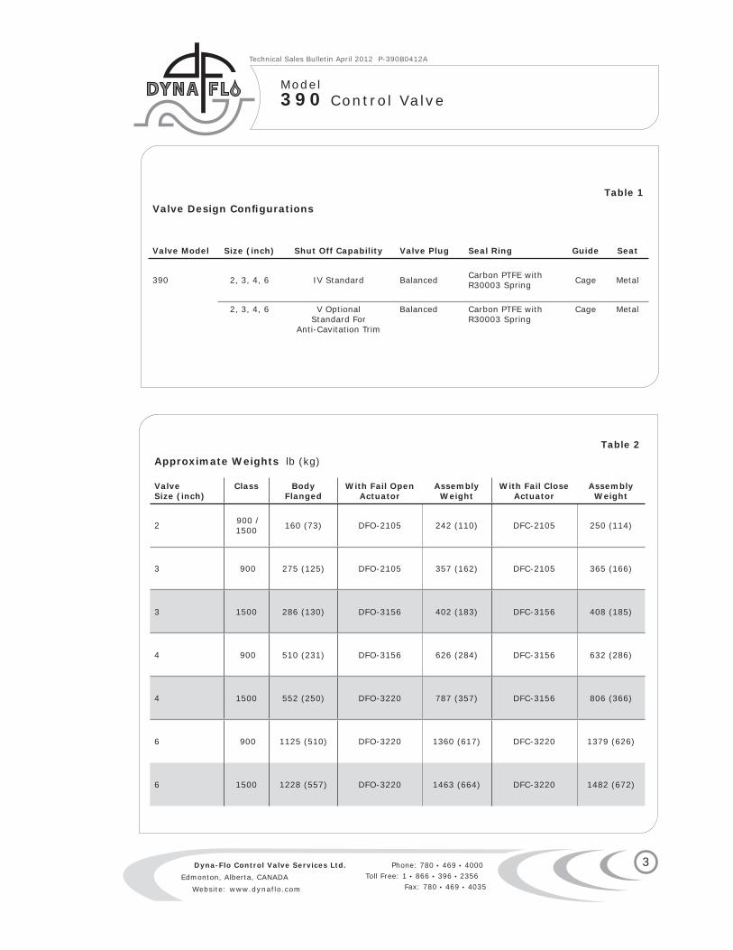
Table 1Valve Design Confi gurations
Valve Model Size (inch) Shut Off Capability Valve Plug Seal Ring Guide Seat
390 2, 3, 4, 6 IV Standard Balanced Carbon PTFE withR30003 Spring Cage Metal
2, 3, 4, 6 V OptionalStandard For
Anti-Cavitation Trim
Balanced Carbon PTFE withR30003 Spring
Cage Metal
Table 2
Approximate Weights lb (kg)
ValveSize (inch)
Class BodyFlanged
With Fail OpenActuator
AssemblyWeight
With Fail CloseActuator
AssemblyWeight
2 900 / 1500 160 (73) DFO-2105 242 (110) DFC-2105 250 (114)
3 900 275 (125) DFO-2105 357 (162) DFC-2105 365 (166)
3 1500 286 (130) DFO-3156 402 (183) DFC-3156 408 (185)
4 900 510 (231) DFO-3156 626 (284) DFC-3156 632 (286)
4 1500 552 (250) DFO-3220 787 (357) DFC-3156 806 (366)
6 900 1125 (510) DFO-3220 1360 (617) DFC-3220 1379 (626)
6 1500 1228 (557) DFO-3220 1463 (664) DFC-3220 1482 (672)
3

Dyna-Flo Control Valve Services Ltd.Edmonton, Alberta, CANADA Website: www.dynaflo.com
Phone: 780 • 469 • 4000Toll Free: 1 • 866 • 396 • 2356 Fax: 780 • 469 • 4035
Technical Sales Bulletin April 2012 P-390B0412A
Model390 Control Valve
4
Table 4Model 390 Dimension C for Standard Bonnet DiametersInches (mm) (Refer to Figure 2)
Valve Size(Inch)
Dimension C
2-13/16 (71) Yoke Boss Diameter 3-9/16 (90) Yoke Boss Diameter 5 (127) Yoke Boss Diameter
2 10.31 (261) 10.56 (267) —
3 12.69 (322) 12.25 (311) —
4 — 11.81 (300) —
6 — 14.38 (365) 15.81 (402)
Table 3Models 390 Standard Valve Dimensions Inches (mm) (Refer to Figure 2)
Valve Size
ASME Class
ActuatorSize
DimensionA B D D E
DFO DFC
2”
900 / 1500 RF
2105 14.75 (375) 3.06 (78) 25.90 (658) 30.30 (770) 16.00 (406)
900 / 1500 RTJ
2105 14.88 (378) 3.06 (78) 25.90 (658) 30.30 (770) 16.00 (406)
3”
900 RF 2105 17.38 (441) 4.75 (121) 25.90 (658) 30.30 (770) 16.00 (406)
900 RTJ 2105 17.50 (445) 4.75 (121) 25.90 (658) 30.30 (770) 16.00 (406)
1500 RF 2156 18.13 (460) 4.75 (121) 25.80 (655) 29.40 (747) 18.62 (473)
1500 RTJ 2156 18.25 (464) 4.75 (121) 25.80 (655) 29.40 (747) 18.62 (473)
3”
900 RF 3156 17.38 (441) 4.75 (121) 28.40 (721) 30.90 (785) 18.62 (473)
900 RTJ 3156 17.50 (445) 4.75 (121) 28.40 (721) 30.90 (785) 18.62 (473)
1500 RF 3156 18.13 (461) 4.75 (121) 28.40 (721) 30.90 (785) 18.62 (473)
1500 RTJ 3156 18.25 (464) 4.75 (121) 28.40 (721) 30.90 (785) 18.62 (473)
4”
900 RF 3156 20.12 (511) 6.88 (175) 28.40 (721) 30.90 (785) 18.62 (473)
900 RTJ 3156 20.25 (514) 6.88 (175) 28.40 (721) 30.90 (785) 18.62 (473)
1500 RF 3220 20.88 (530) 6.88 (175) 33.10 (841) 36.80 (935) 21.12 (536)
1500 RTJ 3220 21.00 (533) 6.88 (175) 33.10 (841) 36.80 (935) 21.12 (536)
6”900 RF 3220 28.12 (714) 9.75 (248) 33.10 (841) 36.80 (935) 21.12 (536)
900 RTJ 3220 28.25 (718) 9.75 (248) 33.10 (841) 36.80 (935) 21.12 (536)
1500 RF 3220 30.25 (768) 10.35 (263) 33.10 (841) 36.80 (935) 21.12 (536)
1500 RTJ 3220 30.50 (775) 10.35 (263) 33.10 (841) 36.80 (935) 21.12 (536)

Dyna-Flo Control Valve Services Ltd.Edmonton, Alberta, CANADA Website: www.dynaflo.com
Phone: 780 • 469 • 4000Toll Free: 1 • 866 • 396 • 2356 Fax: 780 • 469 • 4035
Technical Sales Bulletin April 2012 P-390B0412A
Model390 Control Valve
5
Figure 2 Typical Valve Assembly with Type DFC or DFO
F Dimension: 2” Valve 6.88” (175 mm)
3” Valve 6.88” (175 mm)
3” Valve 9.12” (232 mm) For DFC/DFO 3156
4” Valve 9.12” (232 mm)
6” Valve 9.12” (232 mm)
F
D
E
A
LCCDYNAFLO
390
C
B
Table 5Model 392 Dimension C for Extension BonnetsInches (mm) (Refer to Figure 2)
Valve SizeDimension C
2-13/16 (71) Yoke Boss Diameter
3-9/16 (90) Yoke Boss Diameter
5 (127) Yoke Boss Diameter
1” 15.12 (384) 15.75 (400) -
2” Standard 16.94 (430) 17.56 (446) 19.88 (505)
2” Anti-Cavitation2-stage 17.62 (448) 18.25 (464) 20.38 (518)
2” Anti-Cavitation3-stage 16.94 (430) 17.56 (446) 19.88 (505)

Dyna-Flo Control Valve Services Ltd.Edmonton, Alberta, CANADA Website: www.dynaflo.com
Phone: 780 • 469 • 4000Toll Free: 1 • 866 • 396 • 2356 Fax: 780 • 469 • 4035
Technical Sales Bulletin April 2012 P-390B0412A
Model390 Control Valve
6
Table 6Models 390 Valve Sizing Coeffi cients
Linear - Flow Down
ValveSize
PortInches (mm)
TravelInches (mm) Coeffi cient
Percentage of Valve Travel
10% 20% 30% 40% 50% 60% 70% 80% 90% 100%
2” 1-7/8 (47.6) 1-1/2 (38.1) CV - 3.49 12.5 22.9 31.8 38.4 43.0 46.7 49.9 52.1
XT - 0.811 0.632 0.682 0.743 0.829 0.78 0.743 0.726 0.697
FL 0.91 0.91 0.91 0.91 0.91 0.91 0.91 0.91 0.91 0.91
3” 2-7/8 (73) 2 (50.8) CV - 8.72 31.5 55.1 74.6 89.4 101 110 117 121
XT - 0.589 0.589 0.653 0.728 0.775 0.795 0.791 0.777 0.773
FL 0.93 0.93 0.93 0.93 0.93 0.93 0.93 0.93 0.93 0.93
4” 3-5/8 (92.1) 2 (50.8) CV 6.91 26.5 26.5 86.4 117 143 165 182 194 201
XT 0.327 0.581 0.581 0.509 0.525 0.602 0.673 0.708 0.714 0.726
FL 0.91 0.91 0.91 0.91 0.91 0.91 0.91 0.91 0.91 0.91
6” 5-3/8 (136.5) 3 (76.2) CV 8.78 63.3 149 231 298 351 385 407 424 425
XT 0.763 0.613 0.544 0.573 0.620 0.670 0.721 0.745 0.709 0.726
FL 0.91 0.91 0.91 0.91 0.91 0.91 0.91 0.91 0.91 0.91
Equal Percent - Flow Down
ValveSize
PortInches (mm)
TravelInches (mm) Coeffi cient
Percentage of Valve Travel
10% 20% 30% 40% 50% 60% 70% 80% 90% 100%
2” 1-7/8 (47.6) 1-1/8 (28.6) CV - 1.02 3.26 7.53 13.3 19.8 26.4 32.0 36.2 41.0
XT - 0.745 0.619 0.595 0.587 0.593 0.633 0.721 0.791 0.791
FL 0.93 0.93 0.93 0.93 0.93 0.93 0.93 0.93 0.93 0.93
3” 2-7/8 (73) 1-1/2 (38.1) CV - 1.21 4.21 11.3 23.0 37.6 53.2 69.5 85.3 92.5
XT - 0.954 0.761 0.600 0.558 0.592 0.661 0.705 0.706 0.762
FL 0.92 0.92 0.92 0.92 0.92 0.92 0.92 0.92 0.92 0.92
4” 3-5/8 (92.1) 1-1/2 (38.1) CV 3.12 7.35 13.9 23.4 37.9 60.1 90.6 123 147 164
XT 0.676 0.551 0.524 0.488 0.449 0.443 0.463 0.509 0.569 0.674
FL 0.85 0.85 0.85 0.85 0.85 0.85 0.85 0.85 0.85 0.85
6” 5-3/8 (136.5) 2-1/2 (63.5) CV 3.9 13.3 23.1 36.2 63.0 105 156 217 280 319
XT 0.961 0.686 0.615 0.584 0.540 0.513 0.496 0.480 0.513 0.586
FL 0.82 0.82 0.82 0.82 0.82 0.82 0.82 0.82 0.82 0.82

Dyna-Flo Control Valve Services Ltd.Edmonton, Alberta, CANADA Website: www.dynaflo.com
Phone: 780 • 469 • 4000Toll Free: 1 • 866 • 396 • 2356 Fax: 780 • 469 • 4035
Technical Sales Bulletin April 2012 P-390B0412A
Model390 Control Valve
For quick opening valve characteristics please contact Dyna-Flo
Relationships of Note:
C1 = 39.76 XT
CG = CVC1
KM = FL2
7
Table 7Modifi ed Equal Percent - Flow Down
ValveSize
PortInches (mm)
TravelInches (mm) Coeffi cient
Percentage of Valve Travel
10% 20% 30% 40% 50% 60% 70% 80% 90% 100%
2” 1-7/8 (47.6) 1-1/2 (38.1) CV - 2.28 7.52 15.7 24.1 31.6 38.2 43.5 46.7 48.7
XT - 0.641 0.571 0.584 0.634 0.698 0.778 0.803 0.771 0.760
FL 0.93 0.93 0.93 0.93 0.93 0.93 0.93 0.93 0.93 0.93
3” 2-7/8 (73) 2 (50.8) CV 0.475 3.07 11.8 26.8 46.6 69.3 89.5 100 103 114
XT 0.949 0.712 0.55 0.604 0.682 0.697 0.706 0.762 0.856 0.771
FL 0.95 0.95 0.95 0.95 0.95 0.95 0.95 0.95 0.95 0.95
4” 3-5/8 (92.1) 2 (50.8) CV 4.33 11.3 23.3 45.0 79.6 121 155 176 192 202
XT 0.624 0.523 0.482 0.45 0.453 0.502 0.599 0.696 0.723 0.735
FL 0.89 0.89 0.89 0.89 0.89 0.89 0.89 0.89 0.89 0.89
6” 5-3/8 (136.5) 3 (76.2) CV 5.22 16.6 30.8 55.0 100 168 241 299 351 378
XT 0.883 0.725 0.571 0.597 0.592 0.514 0.526 0.623 0.667 0.717
FL 0.89 0.89 0.89 0.89 0.89 0.89 0.89 0.89 0.89 0.89
! NOTE ! - Modifi ed Equal Percent is a factor of travel and requires no special trim options above Equal Percent.
Table 8Low-Noise 3 (A1) - Flow Up
ValveSize
PortInches (mm)
TravelInches (mm) Coeffi cient
Percentage of Valve Travel
10% 20% 30% 40% 50% 60% 70% 80% 90% 100%
2” 1-7/8 (47.6) 1-1/2 (38.1) CV 3.00 7.70 13.0 17.8 22.3 26.4 31.0 35.3 39.0 42.0
XT 0.516 0.602 0.604 0.610 0.607 0.618 0.608 0.607 0.612 0.608
FL 0.80 0.80 0.80 0.80 0.80 0.80 0.80 0.80 0.80 0.80
3” 2-7/8 (73) 2 (50.8) CV 6.60 24.1 42.1 58.9 74.1 86.8 97.4 105 110 111
XT 0.727 0.610 0.560 0.558 0.588 0.641 0.687 0.723 0.738 0.772
FL 0.80 0.80 0.80 0.80 0.80 0.80 0.80 0.80 0.80 0.80
4” 3-5/8 (92.1) 2 (50.8) CV 7.56 27.3 50.1 71.5 90.8 109 126 142 155 162
XT 0.625 0.586 0.545 0.519 0.520 0.542 0.577 0.614 0.640 0.674
FL 0.80 0.80 0.80 0.80 0.80 0.80 0.80 0.80 0.80 0.80
6” 5-3/8 (136.5) 3 (76.2) CV 28.6 66.4 103 142 180 220 253 284 308 324
XT 0.423 0.513 0.533 0.525 0.557 0.535 0.543 0.560 0.598 0.627
FL 0.80 0.80 0.80 0.80 0.80 0.80 0.80 0.80 0.80 0.80
NOTE: For other noise reduction levels consult Dyna-Flo.

Dyna-Flo Control Valve Services Ltd.Edmonton, Alberta, CANADA Website: www.dynaflo.com
Phone: 780 • 469 • 4000Toll Free: 1 • 866 • 396 • 2356 Fax: 780 • 469 • 4035
Technical Sales Bulletin April 2012 P-390B0412A
Model390 Control Valve
8
Table 9Models 390 Valve Sizing Coeffi cientsTwo Stage Anti-Cavitation - Flow Down
ValveSize
PortInches (mm)
TravelInches (mm) Coeffi cient
Percentage of Valve Travel
10% 20% 30% 40% 50% 60% 70% 80% 90% 100%
2” 1-3/4 (44.5) 2 (50.8) CV 1.07 1.97 3.29 4.86 6.58 8.36 10.1 11.7 13.0 14.0
FL 0.98 0.98 0.98 0.98 0.98 0.98 0.98 0.98 0.98 0.98
3” 2-1/2 (63.5) 2-1/2 (63.5) CV 1.46 4.98 9.24 13.2 17.0 20.7 24.7 28.5 31.9 34.4
FL 0.98 0.98 0.98 0.98 0.98 0.98 0.98 0.98 0.98 0.98
4” 3-7/16 (87.3) 3 (76.2) CV 2.61 9.01 15.6 21.8 28.3 34.8 40.4 46.4 52.2 58.0
FL 0.98 0.98 0.98 0.98 0.98 0.98 0.98 0.98 0.98 0.98
6” 5-1/4 (133.4) 4 (101.6) CV 7.50 20.7 33.8 47.0 60.1 73.3 87.0 100 112 123
FL 0.98 0.98 0.98 0.98 0.98 0.98 0.98 0.98 0.98 0.98
Minimum Throttling Cv2
Valve Size 2 inch 3 inch 4 inch 6 inch
0.580 0.720 0.900 1.72
1 The 2 inch three stage anti-cavitation valves have unbalanced plugs, these valves are of a Model 392 valve design.2 Valves should not be throttled at a Cv less than the specifi ed minimum throttling Cv for extended periods of time, erosion damage to valve trim may occur.NOTE: All FL values are at 100% travel.
Models 390 Valve Sizing Coeffi cientsThree Stage Anti-Cavitation - Flow Down
ValveSize
PortInches (mm)
TravelInches (mm) Coeffi cient
Percentage of Valve Travel
10% 20% 30% 40% 50% 60% 70% 80% 90% 100%
2”1 1 (25.4)1 2 (50.8) CV 0.272 1.10 1.98 2.80 3.63 4.46 5.30 6.07 6.61 6.73
FL 0.99 0.99 0.99 0.99 0.99 0.99 0.99 0.99 0.99 0.99
3” 1-7/8 (47.6) 2-1/2 (63.5) CV 0.747 20.0 3.92 6.15 8.00 9.50 11.0 12.8 14.9 16.5
FL 0.99 0.99 0.99 0.99 0.99 0.99 0.99 0.99 0.99 0.99
4” 2-7/8 (73) 3 (76.2) CV 2.80 5.50 8.30 11.0 13.9 16.7 19.4 22.2 25.0 27.8
FL 0.99 0.99 0.99 0.99 0.99 0.99 0.99 0.99 0.99 0.99
6” 4-9/16 (115.9) 4 (101.6) CV 6.10 13.2 19.8 26.1 34.1 41.5 48.2 54.5 60.9 65.0
FL 0.99 0.99 0.99 0.99 0.99 0.99 0.99 0.99 0.99 0.99
Minimum Throttling Cv2
Valve Size 2 inch 3 inch 4 inch 6 inch
0.590 1.20 1.70 3.10
1 The 2 inch three stage anti-cavitation valves have unbalanced plugs, these valves are of a Model 392 valve design.2 Valves should not be throttled at a Cv less than the specifi ed minimum throttling Cv for extended periods of time, erosion damage to valve trim may occur.NOTE: All FL values are at 100% travel.
For Relationships of Note See Page 7.

Dyna-Flo Control Valve Services Ltd.Edmonton, Alberta, CANADA Website: www.dynaflo.com
Phone: 780 • 469 • 4000Toll Free: 1 • 866 • 396 • 2356 Fax: 780 • 469 • 4035
Technical Sales Bulletin April 2012 P-390B0412A
Model390 Control Valve
9
Key Part Description NACE Construction (2002)1 BODY ASTM (SA352 LCC), ASTM (A215 WCC)
2 BONNET ASTM (SA352 LCC), ASTM (A215 WCC)
3 PACKING BOX RING S31600
5 LANTERN RING S31600
6 RETAINING RING S30200
8 V-RING PACKING SET PTFE (Double)
9 PACKING FOLLOWER S31600
10 STEM WIPER FELT
11 CAGE S17400 DH1150
12 VALVE PLUG / STEM ASS’Y
S31600 with CoCr-A SEAT & GUIDES20910 Stem
13 SEAT RING S31600-CoCr-A
14 SEAL RING CARBON / PTFE / R30003
15 BACKUP RING S31600
16 PACKING FLANGE CARBON STEEL-PLATED
17 PACKING NUT SA-194 2H
18 PACKING STUD SA-193 B7
19 BONNET STUD SA-193 B7M
20 BONNET NUT SA-194 2HM
21 SEAT RING GASKET N06600 / GRAPHITE
22 BONNET GASKET N06600 / GRAPHITE
Table 10Typical Construction MaterialsKey Part Description Standard Construction CF8M Construction1 BODY ASTM (SA352 LCC), ASTM (A215 WCC) ASTM (SA351 CF8M)
2 BONNET ASTM (SA352 LCC), ASTM (A215 WCC) ASTM (SA351 CF8M)
3 PACKING BOX RING S31600 S31600
4 PACKING SPRING S30400 -
5 LANTERN RING - S31600
6 RETAINING RING S30200 S30200
7 SPECIAL WASHER S30400 -
8 V-RING PACKING SET PTFE PTFE (Double)
9 PACKING FOLLOWER S31600 S31600
10 STEM WIPER FELT FELT
11 CAGE S17400 S31600 / ENC
12 VALVE PLUG / STEM ASS’Y
S41600 PLUG/S20910 STEM
S31600 with CoCr-A SEAT & GUIDES20910 Stem
13 SEAT RING S41600 S31600-CoCr-A
14 SEAL RING CARBON / PTFE / R30003 CARBON / PTFE / R30003
15 BACKUP RING S31600 S31600
16 PACKING FLANGE CARBON STEEL-PLATED CARBON STEEL-PLATED
17 PACKING NUT SA-194 2H 8M
18 PACKING STUD SA-193 B7 SA-194 B8M
19 BONNET STUD SA-193 B7 SA-194 B8M
20 BONNET NUT SA-194 2H 8M
21 SEAT RING GASKET N06600 / GRAPHITE N06600 / GRAPHITE
22 BONNET GASKET N06600 / GRAPHITE N06600 / GRAPHITE

Dyna-Flo Control Valve Services Ltd.Edmonton, Alberta, CANADA Website: www.dynaflo.com
Phone: 780 • 469 • 4000Toll Free: 1 • 866 • 396 • 2356 Fax: 780 • 469 • 4035
Technical Sales Bulletin April 2012 P-390B0412A
Model390 Control Valve
10
Figure 3 Cross-section of 390 Series Control Valve
PACKING FLANGE(Key 16)
VALVE STEM (Key 12)
BONNET(Key 2)
PACKING SET (Key 8)
PACKING BOX RING(Key 3)
SEAL RING(Key 14)
BACK UP RING(Key 15)
RETAINING RING (Key 6)
VALVE PLUG (Key 12)
SEAL RING(Key 14)
BONNET GASKET(Key 22)
CAGE(Key 11)
390 BODY(Key 1)
SEAT RING (Key 13)
SEAT RING GASKET(Key 21)
SPRING (Key 4)
WASHER(Key 7)
FOLLOWER(Key 9)
FLOW UPFLOW DOWN LANTERN RING
DETAIL
VALVE PLUG(Key 12)
PACKING NUT(Key 17)
PACKING STUD(Key 18)
BONNET STUD (Key 19)
BONNET NUT(Key 20)
UPPER WIPER(Key 10)
(Key 8)
(Key 8)
(Key 5)

Dyna-Flo Control Valve Services Ltd.Edmonton, Alberta, CANADA Website: www.dynaflo.com
Phone: 780 • 469 • 4000Toll Free: 1 • 866 • 396 • 2356 Fax: 780 • 469 • 4035
Technical Sales Bulletin April 2012 P-390B0412A
Model390 Control Valve
11
PACKING FLANGE
TYPICAL LIVE LOADED PACKING WITH PTFE V-RING PACKING SETS
TYPICAL LIVE LOADED PACKING WITH GRAPHITE PACKING RINGS
STANDARD HIGH TEMPERATURE PACKING DIAGRAM
STANDARD SINGLE PTFE PACKING DIAGRAM
O-RING
SPRING WASHERS
LIVE LOADED PACKING FOLLOWER
PACKING FLANGE
O-RING
SPRING WASHERS
LIVE LOADED PACKING FOLLOWER
LANTERN RING
GRAPHITE PACKING RINGS
GUIDE BUSHING
GRAPHITE PACKING RINGS
GRAPHITEPACKING RINGS
WASHER
SPRING
LANTERN RING
PACKINGBOX RING
V-RINGPACKING SET
PACKINGBOX RING
PACKING FOLLOWER STEM
WIPER
PACKING FLANGE
LANTERN RING
PACKINGBOX RING LOWER
WIPER
PACKING FLANGE PACKING
FOLLOWER
STEMWIPER
V-RINGPACKING SET
PACKINGBOX RING
LOWERWIPER
Figure 4 Typical Packing Arrangements

Dyna-Flo Control Valve Services Ltd.Edmonton, Alberta, CANADA Website: www.dynaflo.com
Phone: 780 • 469 • 4000Toll Free: 1 • 866 • 396 • 2356 Fax: 780 • 469 • 4035
Technical Sales Bulletin April 2012 P-390B0412A
Model390 Control Valve
12
Table 11Fail Open ActuatorShut Off Capabilities for Model 390Metal Seat, Class IV Control Valve35 psig supply pressure
Valve Actuator Size Size Pressure Drop Psig (kPag)(inch) DFO - 2105 DFO - 2156 DFO - 3105 DFO - 3156 DFO - 3220
2” 3750 (25,855)1 3750 (25,855)1 — — —
3” 3750 (25,855)2 3750 (25,855)1 3750 (25,855)2 3750 (25,855)1 —
4” — — — 3750 (25,855)3 3750 (25,855)1
6” — — — — 2280 (15,720)4
Note1 - 6 to 26 Psig bench range2 - 6 to 24 Psig bench range3 - 6 to 22 Psig bench range4 - 6 to 17 Psig bench range
Table 12Fail Closed ActuatorShut Off Capabilities for Model 390Metal Seat, Class IV Control Valve35 psig supply pressure
Valve Actuator Size Size Pressure Drop Psig (kPag)(inch) DFC - 2105 DFC - 2156 DFC - 3105 DFC - 3156 DFC - 3220
2” 3750 (25,855)1 3750 (25,855)1 — — —
3” 3750 (25,855)2 3750 (25,855)1 3750 (25,855)2 3750 (25,855)1 —
4” — — — 2280 (15,720)2 3750 (25,855)3
6” — — — — 2280 (15,720)4
Note1 - 6 to 30 psig Bench Range2 - 9 to 30 psig Bench Range3 - 15 to 30 psig Bench Range4 - 18 to 30 Psig Bench Range with a DFC4-3220 Actuator

Dyna-Flo Control Valve Services Ltd.Edmonton, Alberta, CANADA Website: www.dynaflo.com
Phone: 780 • 469 • 4000Toll Free: 1 • 866 • 396 • 2356 Fax: 780 • 469 • 4035
Technical Sales Bulletin April 2012 P-390B0412A
Model390 Control Valve
13
Table 13
Port Diameters, Valve Plug Travel and Yoke Boss Diameter
Valve Size Port Diameter Max Valve Travel Yoke Boss DiameterInch Inch (mm) Inch (mm) Inch (mm)
Stem Valve
2” Linear, Mod. Equal Percent& Low-Noise 1 7/8 (47.6) 1-1/2 (38.1)
1/2 (12.7) 2-13/16 (71.4)
3/4 (19.1) 3-9/16 (90.5)
2” Equal Percent 1-7/8 (47.6) 1-1/8 (28.6)1/2 (12.7) 2-13/16 (71.4)
3/4 (19.1) 3-9/16 (90.5)
2” Anti-Cavitation Stage 2 1-3/4 (44.5) 2 (50.8)1/2 (12.7) 2-13/16 (71.4)
3/4 (19.1) 3-9/16 (90.5)
2” Anti-Cavitation Stage 3 1 (25.4) 2 (50.8) 3/4 (19.1) 3-9/16 (90.5)
3” Linear, Mod. Equal Percent& Low-Noise 2-7/8 (73) 2 (50.8)
1/2 (12.7) 2-13/16 (71.4)
3/4 (19.1) 3-9/16 (90.5)
1 (25.4) 5 (127)
3” Equal Percent 2-7/8 (73) 1-1/2 (38.1)
1/2 (12.7) 2-13/16 (71.4)
3/4 (19.1) 3-9/16 (90.5)
1 (25.4) 5 (127)
3” Anti-Cavitation Stage 2 2-1/2 (63.5) 2-1/2 (63.5)
1/2 (12.7) 2-13/16 (71.4)
3/4 (19.1) 3-9/16 (90.5)
1 (25.4) 5 (127)
3” Anti-Cavitation Stage 3 1-7/8 (47.6) 2-1/2 (63.5)
1/2 (12.7) 2-13/16 (71.4)
3/4 (19.1) 3-9/16 (90.5)
1 (25.4) 5 (127)
4” Linear, Mod. Equal Percent& Low-Noise 3-5/8 (98) 2 (50.8)
3/4 (19.1) 3-9/16 (90.5)
1 (25.4) 5 (127)
4” Equal Percent 3-5/8 (92.1) 1-1/2 (38.1)3/4 (19.1) 3-9/16 (90.5)
1 (25.4) 5 (127)
4” Anti-Cavitation Stage 2 3-7/16 (87.3) 3 (76.2)3/4 (19.1) 3-9/16 (90.5)
1 (25.4) 5 (127)
4” Anti-Cavitation Stage 3 2-7/8 (73) 3 (76.2)3/4 (19.1) 3-9/16 (90.5)
1 (25.4) 5 (127)
6” Linear, Mod. Equal Percent& Low-Noise 5-3/8 (136.5) 3 (76.2)
3/4 (19.1) 3-9/16 (90.5)
1 (25.4) 5 (127)
1-1/4 (31.8) 5 (127)
6” Equal Percent 5-3/8 (136.5) 2-1/2 (63.5)
3/4 (19.1) 3-9/16 (90.5)
1 (25.4) 5 (127)
1-1/4 (31.8) 5 (127)
6” Anti-Cavitation Stage 2 5-1/4 (133.4) 4 (101.6)
3/4 (19.1) 3-9/16 (90.5)
1 (25.4) 5 (127)
1-1/4 (31.8) 5 (127)
6” Anti-Cavitation Stage 3 4-9/16 (115.9) 4 (101.6)
3/4 (19.1) 3-9/16 (90.5)
1 (25.4) 5 (127)
1-1/4 (31.8) 5 (127)

Dyna-Flo Control Valve Services Ltd.Edmonton, Alberta, CANADA Website: www.dynaflo.com
Phone: 780 • 469 • 4000Toll Free: 1 • 866 • 396 • 2356 Fax: 780 • 469 • 4035
Technical Sales Bulletin April 2012 P-390B0412A
Model390 Control Valve
14
Table 16Materials and Temperature Limits for Parts other than Valve Body and Trim
Part Material MinimumTemperature
MaximumTemperature
Backup Ring S31600 -325oF (198oC) 1100oF (593oC)
Retaining Ring S30200 -425oF (-254oC) 1100oF (593oC)
Seal Ring PTFE with R30003 Spring -100oF (-73oC) 450oF (232oC)
Bonnet / Cage Gasket N06600 / Graphite -400oF (-240oC) 800oF (427oC)
Seat Ring Gasket N06600 / Graphite -400oF (-240oC) 800oF (427oC)
Packing PTFE V-Ring -40oF (-40oC) 450oF (232oC)
Graphite Ribbon / Filament -425oF (-254oC) 1000oF (537oC)
Body to Bonnet Studs (NACE-2002) B7M (LCC Body) -50oF (-46oC) 700oF (371oC)
Body to Bonnet Nuts (NACE-2002) 2HM (LCC Body) -50oF (-46oC) 700oF (371oC)
For NACE 2003 body to bonnet studs and nuts please contact Dyna-Flo
1 Maximum temperature limited by body material (LCC body temperature limitation shown).
2 Check body material temperature limitations.
3 Temperatures need to be considered when specifying trim materials for elevated temperatures in corrosive environments, consult factory for further information.
4 Trim Spec relates to Model Numbering System on Page 12.
NOTE: Bonnet Bolting refer to Table 14.
Table 14Common Trim Options and Temperature Ratings
Trim4
Spec Valve Plug Stem Cage Seat RingMinimum3
TemperatureMaximumTemperature
oF (oC) oF (oC)
S S41600 S20910 S17400 PH S41600 -20 (-29) 650 (343)1
NS31600 /CoCr-ASeat and Guide
S20910 S17400 PH DHT
S31600 /CoCr-A -50 (-46) 650 (343)
CS31600 /CoCr-ASeat and Guide
S20910 S31600 ENC S31600 /CoCr-A -50 (-46)2 750 (399)2
Table 15
Valve Bolting Temperature Limitations Stud Material Temperature Limitation
B7 -50OF to 900OF (-46OC TO 482OC)
B7M -50OF TO 900OF (-46OC TO 482OC)
B8M -325OF TO 1500OF (-198OC TO 816OC)
S17400 DH 1150 -50OF TO 650OF (-46OC TO 343OC)
Nut Material Temperature Limitation
2H, 2HM & 8M Not Limiting Factors

Dyna-Flo Control Valve Services Ltd.Edmonton, Alberta, CANADA Website: www.dynaflo.com
Phone: 780 • 469 • 4000Toll Free: 1 • 866 • 396 • 2356 Fax: 780 • 469 • 4035
Technical Sales Bulletin April 2012 P-390B0412A
Model390 Control Valve
15
6000
5000
4000
3000
2000
1000
0
-50 200 400 600 800 1000 1200
MA
X W
OR
KIN
G P
RES
SU
RE
(psi
)
TEMPERATURE (oF)
LCC STEEL VALVE
CLASS900
CLASS1500
1200
6000
5000
4000
3000
2000
1000
0
-325
CLASS900
CLASS1500
MA
X W
OR
KIN
G P
RES
SU
RE
(psi
)
TEMPERATURE (oF)
CF8M STAINLESS STEEL VALVE
200 400 600 800 1000
TEMPERATURE (oC) -46
0 200 400 600
TEMPERATURE (oC) 200-198 400 600
6000
5000
4000
3000
2000
1000
0
-20 200 400 600 800 1000 1200
MA
X W
OR
KIN
G P
RES
SU
RE
(psi
)
TEMPERATURE (oF)
WCC STEEL VALVE
CLASS900
CLASS1500
TEMPERATURE (oC) -29
0 200 400 600
0
10,000
20,000
30,000
40,000
MA
X W
OR
KIN
G P
RES
SU
RE
(kP
a)
0
10,000
20,000
30,000
40,000
MA
X W
OR
KIN
G P
RES
SU
RE
(kP
a)
0
10,000
20,000
30,000
40,000
MA
X W
OR
KIN
G P
RES
SU
RE
(kP
a)
Figure 6 Pressure / Temperature Charts as per ASME B16.34
1200
6000
5000
4000
3000
2000
1000
0-100
PR
ESS
UR
E D
RO
P (
psi
)
TEMPERATURE (oF)
TRIM SPEC C
200 400 600 800 1000
TEMPERATURE (oC)200
-73400 600
1000
20,000
40,000
PR
ESS
UR
E D
RO
P (
kPa)
DIF
FER
ENTI
AL
0 100 300 500
5000
10,000
15,000
25,000
30,000
35,000
45,000
1200
6000
5000
4000
3000
2000
1000
0-20
PR
ESS
UR
E D
RO
P (
psi
)
200 400 600 800 1000
TEMPERATURE (oC)200
-29400 600
1000
20,000
40,000
0 100 300 500
5000
10,000
15,000
25,000
30,000
35,000
45,000
1200
6000
5000
4000
3000
2000
1000
0-100
PR
ESS
UR
E D
RO
P (
psi
)
TEMPERATURE (oF)
TRIM SPEC N (NACE)
200 400 600 800 1000
TEMPERATURE (oC)200
-40400 600
1000
20,000
40,000
PR
ESS
UR
E D
RO
P (
kPa)
DIF
FER
ENTI
AL
0 100 300 500
5000
10,000
15,000
25,000
30,000
35,000
45,000
TEMPERATURE (oF)
TRIM SPEC S
PR
ESS
UR
E D
RO
P (
kPa)
DIF
FER
ENTI
AL
Figure 5 Trim Material Pressure / Temperature Limitations

Dyna-Flo Control Valve Services Ltd.Edmonton, Alberta, CANADA Website: www.dynaflo.com
Phone: 780 • 469 • 4000Toll Free: 1 • 866 • 396 • 2356 Fax: 780 • 469 • 4035
Technical Sales Bulletin April 2012 P-390B0412A
Model390 Control Valve
2 Anti-Cavitation 2 Stage
Dyna-Flo Model 390 Control Valve | Model Numbering System
Sample Part Number
390-3AJ-L2S-EPCode Description
Packing Style
P Spring Loaded PTFE V-Ring
D Double PTFE V-Ring
G Graphite High Temp
Characteristic
L Linear E Equal Percent
Trim
S Standard
N NACE / Low Temp
Body Material
L LCC M CF8M
Connection Style
F RF J RTJ
ASME Rating
A 900 B 1500
Valve Size
2 2 inch
3 3 inch
4 4 inch
P
E
S
L
J
A
3
2
C CF8M Construction
W WCC
3 Anti-Cavitation 3 Stage
C 900/1500
T Live Loaded (PTFE)
Bolting
- B7 / 2H (Standard) A B7M / 2HM-B B8M / 8M C S17400 DH 1150 / 2HM
6 6 inch
M Modified Equal Percent
L Live Loaded (Graphite)
H Low-Noise 3
Bonnet (Standard and Extension)
3-9/16” (90.5 mm) Std.2 2-13/16” (71.4 mm) Std. 3
5 5” (127 mm) Std. A 2-13/16” (71.4 mm) Ext.
C 5” (127 mm) Ext.3-9/16” (90.5 mm) Ext.B
16
! NOTE ! - Modifi ed Equal Percent is a factor of travel and requires no special parts or trim options that differ from Equal Percent.
Ord
eri
ng
Gu
ide
Our Commitment of QualityDyna-Flo is committed to continuous improvement. All efforts have been taken to maximize the accuracy of this information. Without notifi cation, product specifi cations and designs may be modifi ed at any time. The issue of this document is for information only, and does not imply suitability, a warranty, or guarantee for a specifi c service.