dx200 platform commisioning dn9774533x5x0xen
DESCRIPTION
DX200 PlatformTRANSCRIPT
GER4 version 3
Commissioning DX 200 BasedNetwork Elements
Commissioning and Integration Manual2.2DGER4_2PD
DN9774533 © Nokia Corporation 1 (56)Issue 5-0 en Nokia Proprietary and Confidential
Commissioning DX 200 Based Network Elements
The information in this documentation is subject to change without notice and describes onlythe product defined in the introduction of this documentation. This documentation is intendedfor the use of Nokia's customers only for the purposes of the agreement under which thedocumentation is submitted, and no part of it may be reproduced or transmitted in any form ormeans without the prior written permission of Nokia. The documentation has been prepared tobe used by professional and properly trained personnel, and the customer assumes fullresponsibility when using it. Nokia welcomes customer comments as part of the process ofcontinuous development and improvement of the documentation.
The information or statements given in this documentation concerning the suitability, capacity,or performance of the mentioned hardware or software products cannot be considered bindingbut shall be defined in the agreement made between Nokia and the customer. However, Nokiahas made all reasonable efforts to ensure that the instructions contained in the documentationare adequate and free of material errors and omissions. Nokia will, if necessary, explain issueswhich may not be covered by the documentation.
Nokia's liability for any errors in the documentation is limited to the documentary correction oferrors. NOKIA WILL NOT BE RESPONSIBLE IN ANY EVENT FOR ERRORS IN THISDOCUMENTATION OR FOR ANY DAMAGES, INCIDENTAL OR CONSEQUENTIAL(INCLUDING MONETARY LOSSES), that might arise from the use of this documentation orthe information in it.
This documentation and the product it describes are considered protected by copyrightaccording to the applicable laws.
NOKIA logo is a registered trademark of Nokia Corporation.
Other product names mentioned in this documentation may be trademarks of their respectivecompanies, and they are mentioned for identification purposes only.
Copyright © Nokia Corporation 1999. All rights reserved.
DX 200 is a registered trademark of Nokia Telecommunications Oy
2 (56) © Nokia Corporation DN9774533Nokia Proprietary and Confidential Issue 5-0en
Contents
Contents 3
List of figures 5
Summary of changes 7
1 About this manual 111.1 Assumptions 111.2 Scope of application 121.3 Structure of this manual 121.4 Typographical conventions 121.4.1 Fonts 121.4.2 MML commands 13
2 References 152.1 Where to find more information 15
3 Preparing for commissioning 173.1 Prerequisites 173.2 Measurement devices and tools for inspection and testing 173.3 Electrostatic Precautions 183.4 Fault reporting 18
4 Initial inspections 194.1 References 194.2 Cartridges 194.3 Strappings and PROM-programs of plug-in units 194.4 Power supply 204.5 Disk drives 204.6 Unit start-up 204.7 System start-up and working states 214.7.1 System reset 214.7.2 Checking the working states of other units 214.7.3 Loading failure 22
5 Inspecting user interfaces 235.1 References 235.2 The first MML Session and I/O Configuration 245.3 Checking the software package 245.4 Authority check 245.5 Checking the computer unit states 265.6 Alarm Checking 265.7 Checking the I/O configuration 265.8 Terminal parameters of I/O devices 265.9 Video display 285.10 Line printer 295.11 Magnetic Tape Unit 305.12 Cartridge tape unit 32
DN9774533 © Nokia Corporation 3 (56)Issue 5-0 en Nokia Proprietary and Confidential
Commissioning DX 200 Based Network Elements
5.13 Print-outs during commissioning 34
6 Hardware database configuration 356.1 References 356.2 Checking the hardware database 356.2.1 Checking the cartridges 356.2.2 Checking the plug-in units 366.3 Correcting the Hardware Database 37
7 Inspecting the maintenance system 397.1 References 397.2 Preliminary checks 407.3 Executing unit diagnoses 417.3.1 Message buses 417.3.2 Computer units without an internal PCM circuit 417.3.3 Other computer units 427.3.4 Clock system 427.3.5 Exchange terminals 427.3.6 Subscriber modules 437.3.7 Spare plug-in units 437.4 Wired alarms 447.5 Lamp panel 457.6 Subscriber Measurement 457.6.1 Preparation 457.6.2 Subscriber Control 467.6.3 Checking the existence of subscriber numbers 477.6.4 Routine Measurement 497.6.5 Printing the routine measurement results 507.6.6 Line measurement 507.7 System Maintenance 527.7.1 Alarms 527.7.2 Recovery 53
8 O&M connections 55
4 (56) © Nokia Corporation DN9774533Nokia Proprietary and Confidential Issue 5-0en
List of figures
Figure 1. The phases before and after commissioning. 11
DN9774533 © Nokia Corporation 5 (56)Issue 5-0 en Nokia Proprietary and Confidential
Commissioning DX 200 Based Network Elements
6 (56) © Nokia Corporation DN9774533Nokia Proprietary and Confidential Issue 5-0en
Summary of changes
Changes between document issues are cumulative. Therefore, the latest documentissue contains all changes made to previous issues.
Changes between document issues are cumulative. Therefore, the latest documentissue contains all changes made to previous issues.
Changes made between issues 5 and 4
All chapters of this manual were changed due to new software and hardwarechanges in the DX 200. Many parameter changed. One picture was removed.
Changes made between issues 4 and 3
ABOUT THIS MANUAL
Changed the general software level from GX 10.X. to GX 20.X.
REFERENCES
Updated the list of references.
INITIAL INSPECTIONS
Relocated "Checking the software package" to the end of the chapter.
Clarified the check in "Unit start up".
Steps to check the directories were clarified.
INSPECTING USER INTERFACES
Replaced the term "user identifier" with "user ID".
Removed the unnecessary screen shot on checking the I/O configuration.
Included INDU-unit to the list of possible units.
Removed unnecessary parts of the figure on logical printer files.
Generalized the ISI command under "Video display" by taking away the name ofthe unit.
New first step of "Magnetic tape unit" was taken from the end of the relatedtroubleshooting section. Also, step C was removed as unnecessary from thetroubleshooting list.
DN9774533 © Nokia Corporation 7 (56)Issue 5-0 en Nokia Proprietary and Confidential
Commissioning DX 200 Based Network Elements
Under "Line printer" the "check for state" was changed from WO-EX to WO-ID.
Under "Authority check" five steps were rewritten for clarity. A new step on"profile" was added. The command IAC was corrected to be IAI.
Add the last step to the section on Cartridge tape unit. Also, the IMP commandexample was added.
HARDWARE DATABASE CONFIGURATION
Greatly modified the steps in this chapter for clarity.
INSPECTING THE MAINTENANCE SYSTEM
Removed restrictions on AS7-U/AS7-V diagnosis.
A new test was designed to check the exchange terminals.
Added a command example to the section on Message buses.
Changes made between issues 3 and 2
ABOUT THIS MANUAL
Added sections Structure of this manual and Typographical conventions.
INSPECTING USER INTERFACES
New section called Authority check added.
The first MML-session and I/O congifuration
Updated the information.
Terminal parameters of I/O devices
Updated the Troubleshooting section.
Line printer
Updated the Troubleshooting section.
Magnetic tape unit
Updated the instructions and the Troubleshooting section.
HARDWARE DATABASE CONFIGURATION
Added LIA16 in the section LIA10 is missing from the subscriber moduleconfiguration.
8 (56) © Nokia Corporation DN9774533Nokia Proprietary and Confidential Issue 5-0en
Running unit diagnoses
This section has been totally revised.
CREATING AN O&M CONNECTION
All instructions removed from this chapter. Instructions on how to set up theO&M connections can be found in the following manuals:
• Integration manual
• Operation and Maintenance Connections, Operating manual
DN9774533 © Nokia Corporation 9 (56)Issue 5-0 en Nokia Proprietary and Confidential

Commissioning DX 200 Based Network Elements
10 (56) © Nokia Corporation DN9774533Nokia Proprietary and Confidential Issue 5-0en
About this manual
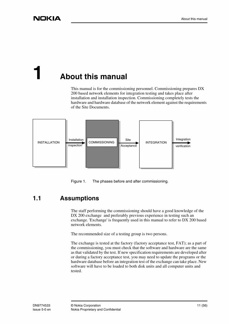
1 About this manualThis manual is for the commissioning personnel. Commissioning prepares DX200 based network elements for integration testing and takes place afterinstallation and installation inspection. Commissioning completely tests thehardware and hardware database of the network element against the requirementsof the Site Documents.
Figure 1. The phases before and after commissioning.
1.1 Assumptions
The staff performing the commissioning should have a good knowledge of theDX 200 exchange and preferably previous experience in testing such anexchange. 'Exchange' is frequently used in this manual to refer to DX 200 basednetwork elements.
The recommended size of a testing group is two persons.
The exchange is tested at the factory (factory acceptance test, FAT); as a part ofthe commissioning, you must check that the software and hardware are the sameas that validated by the test. If new specification requirements are developed afteror during a factory acceptance test, you may need to update the programs or thehardware database before an integration test of the exchange can take place. Newsoftware will have to be loaded to both disk units and all computer units andtested.
INSTALLATION COMMISSIONING INTEGRATIONSite
Acceptance
Integration
verification
Installation
inspection
DN9774533 © Nokia Corporation 11 (56)Issue 5-0 en Nokia Proprietary and Confidential
Commissioning DX 200 Based Network Elements
1.2 Scope of application
This document describes how to commission DX 200 based network elementswith equipment level M92A5 and general software level GX 20.x.
All the operations needed to determine the condition of a network element aredescribed. The main phases of testing should be carried out in the order presentedin this manual.
1.3 Structure of this manual
This manual should be read in normal chapter order. The structure is designed tohelp the reader to get a clear understanding about the commissioning of networkelements.
• Chapters 1-2 - introduce the manual and its contents.
• Chapter 3. Preparing for commissioning - presents the tools and devicesneeded in commissioning and reminds of electrostatic precautions and faultreporting.
• Chapter 4. Initial inspections - describes the checks to be carried out beforeand after the start-up of the exchange.
• Chapter 5. Inspecting user interfaces - describes the checks to be carriedout on I/O devices.
• Chapter 6. Hardware database configuration - describes how to check theconfiguration of the hardware database.
• Chapter 7. Inspecting the maintenance system - describes the checks to becarried out on the maintenance system.
• Chapter 8. O&M connections - introduces the manuals to be used whensetting up O&M connections.
1.4 Typographical conventions
1.4.1 Fonts
Italic Indicates one of the following:a) The title of a manual or chapter/section name in thereferences.
12 (56) © Nokia Corporation DN9774533Nokia Proprietary and Confidential Issue 5-0en
About this manual
For example,'...refer to the Terminal Parameters Handling,Command Reference Manual.b) A word or phrase that is emphasised. For example, 'Allmanuals use the same typographical conventions'.
ZIAT Indicates an MML command.
1.4.2 MML commands
The following presentation is used to show the commands to be entered whenusing the Man-Machine-Language to communicate with the exchange.
Example 1.
Use the IMD command to check the state of the CTU:
ZIMD::CTU,0;
Syntax conventions:
Z Return to the top level menu.The character Z only needs to be typed at the beginning of thecommand if you are entering a command in a differentcommand group or class to the last command entered.
<> Parameter names are displayed within these characters. Theseare not typed in the command.
, Used as a separator between parameters.; Indicates the end of a command.: Delimiter between command blocks.PARAM Capitals indicate a name defined parameter.= This character after a parameter name indicates that a
parameter value or a list of values follows./ Parameter values in a list are separated by this character, e.g.
NAME = Y/N.&/&& '&' means repetition of the parameter and '&&' repetition
with automatic incrementation. A hyphen added to thecharacters above (used with combination parameters only)means that the '&' or '&&' operation concerns the lastelement of the parameter only.
DN9774533 © Nokia Corporation 13 (56)Issue 5-0 en Nokia Proprietary and Confidential

Commissioning DX 200 Based Network Elements
14 (56) © Nokia Corporation DN9774533Nokia Proprietary and Confidential Issue 5-0en
References
2 ReferencesEach chapter begins with a list of related documents. Within the chapters thereferences are marked with Ref whenever possible - e.g. in the Troubleshootingsections the references are not marked.
References within this document are made by giving the chapter or section namewhere additional information can be found.
2.1 Where to find more information
Hardware Configuration Management, Functional Descriptions
Configuration Administration Hardware Configuration Administration, SoftwareArchitecture Descriptions
Logical Files, Quick Reference Guide
Basic Operation and Maintenance System, Functional Descriptions
O&M Communications Protocols, Functional Descriptions
O&M Network Management, Service Block Descriptions
DN9774533 © Nokia Corporation 15 (56)Issue 5-0 en Nokia Proprietary and Confidential

Commissioning DX 200 Based Network Elements
16 (56) © Nokia Corporation DN9774533Nokia Proprietary and Confidential Issue 5-0en
Preparing for commissioning
3 Preparing for commissioning
3.1 Prerequisites
You can start the commissioning when the installation of the exchange has beensuccessfully carried out i.e. you have received the site deficiency reports of theinstallation and any necessary corrections have been carried out.
3.2 Measurement devices and tools for inspection andtesting
The tools required include the following:
• Digital multimeter
• Wrapping tool set for 0.25 mm and 0.40 mm
• Unwrap tool
• Allen key set
• Screwdriver set
• Side cutting pliers
• EPROM circuit release tool (24-28 pins)
• PROM circuit release tool (PLCC)
• Plug-in unit release tool
• Jumper links
• VDU visual display unit, preferably at least two VDUs
• LPT line printer
• Wrist strap and connecting lead
DN9774533 © Nokia Corporation 17 (56)Issue 5-0 en Nokia Proprietary and Confidential
Commissioning DX 200 Based Network Elements
3.3 Electrostatic Precautions
When handling plug-in units, it is important to use Electrostatic Precautions(ESP). This means that the operator must be earthed to equipment racks using anapproved wrist strap and connecting lead. Approved ESP equipment makes aresistive connection to ensure the safety of the operator and to prevent a suddenstatic discharge during connection to the earthing point.
3.4 Fault reporting
If you detect faults during commissioning, fill in the Nokia TelecommunicationsSite Deficiency Report form and send it to your local NTC Customer ServiceCentre.
If software defects occur in the exchange, e.g. if the software versions are old ordo not correspond to the agreement or the code control list delivered together withthe Delivery Lists, fill in a failure report. Contact then immediately the NokiaCustomer Services in order to have the modules replaced/repaired and theDelivery List updated.
18 (56) © Nokia Corporation DN9774533Nokia Proprietary and Confidential Issue 5-0en
Initial inspections
4 Initial inspections
4.1 References
1. Site Documents
2. Release Binder
3. Print-Outs of Starting Phases, Maintenance Manual
4. User's Manual of the Service Terminal, Maintenance Manual
5. Recovery and Unit Working State Administration, Maintenance Manual
6. Software Package Deployment Handling, Operating Manual
7. Software Package Management, Command Reference Manual
4.2 Cartridges
Check the additional wirings on the cartridges, refer to the Site Documents.
4.3 Strappings and PROM-programs of plug-in units
1. Check the required strappings and the locations and versions of PROM-programs.
2. Install the plug-in units in accordance with the Equipment List.
Steps 1 and 2, refer to the Site Documents and Release Binder.
DN9774533 © Nokia Corporation 19 (56)Issue 5-0 en Nokia Proprietary and Confidential
Commissioning DX 200 Based Network Elements
4.4 Power supply
In installation, the supply voltage of racks is usually measured without load. Ifthis measurement has not been made, then follow these simple instructions.Measure the supply voltage with load, that is, plug-in units installed.
1. Turn on the power in all Power Supply Adapter Units at the top of the rack.
2. Check that the voltage in the racks is between -40.5V...-72V.
4.5 Disk drives
Check that the floppy disk drive works as it should, using the following serviceterminal commands:
1. Initialize a floppy disk:
ZMI:F0-<name of the disk>,;
2. Copy a file, e.g. PCMCON, from the hard disk drive to the floppy disk:
ZMM:W0-/LFILES/PCMCONGA.IMG,F0;
3. Write out the main directory of the floppy disk to check that the copyingwas successful:
ZMX:F0;
Ref For more information on the use of service terminalcommands, refer to the User's Manual of the ServiceTerminal, Maintenance Manual.
4.6 Unit start-up
Check all the other units in the following order:
1. Central Memory Unit (CM)
2. Statistical Units (STU)
3. Charging unit (CHU), if applicable
4. All the other units
Troubleshooting: If the computer does not start properly (WO-EX or SP-EX) thendo the following:
20 (56) © Nokia Corporation DN9774533Nokia Proprietary and Confidential Issue 5-0en
Initial inspections
1. Connect a VDU to the lower connector of the CPU.
2. Turn on the power.
After a successful unit start-up, the following message is displayed:
either
READY - WO
or
READY - SP
If the unit start-up fails, change the CPU plug-in unit and try again.
4.7 System start-up and working states
4.7.1 System reset
To start up the entire exchange, reset the OMU and Central Memory (e.g. CM,CAC) units simultaneously by pressing the reset button in the CPU plug-in units.
4.7.2 Checking the working states of other units
To check the working states of other units
1. Activate RCBUGG by the following Service Terminal command, refer tothe Print-Outs of Starting Phases, Maintenance Manual:
ZLP:U,RCB;
2. Use the RCBUGG command USI to check the working states of units.
ZUSIC:COMP;
3. Ensure that no units are in restart state. The correct states are SP-EX, WO-EX.
Ref For more information on the unit states, refer to the Recoveryand Unit Working State Administration, Maintenance ManualFor more information on the use of service terminalcommands, refer to the User's Manual of the ServiceTerminal, Maintenance Manual
DN9774533 © Nokia Corporation 21 (56)Issue 5-0 en Nokia Proprietary and Confidential
Commissioning DX 200 Based Network Elements
4.7.3 Loading failure
If the unit start fails, refer to the Print-Outs of Starting Phases, MaintenanceManual.
If you cannot solve the problem with the help of the above-mentioned manual,refer to the section Unit Diagnosis for more information.
22 (56) © Nokia Corporation DN9774533Nokia Proprietary and Confidential Issue 5-0en
Inspecting user interfaces
5 Inspecting user interfacesThis chapter describes how to open an MML session and how to test andconfigure I/O devices.
5.1 References
1. I/O Device Working States, Command Reference Manual
2. Site Documents
3. Installation Manual
4. Terminal Parameters Handling, Command Reference Manual
5. Recovery and Unit Working State Administration, Maintenance Manual
6. Magnetic Tape Handling, Operating Manual
7. Magnetic Tape Handling, Command Reference Manual
8. Changing of Mass Memory Units, Maintenance Manual
9. I/O Configuration Handling, Command Reference Manual
10. I/O Configuration Handling, Operating Manual
11. Equipment Management, Command Reference Manual
12. Diagnostics and Testing, Maintenance Manual
13. Disk File And Directory Handling, Command Reference Manual
14. Disk File And Directory Handling, Operating Manual
15. I/O File Backup, Command Reference Manual
16. MMI System Authority Handling, Command Reference Manual
17. Print-outs of Starting Phases, Maintenance Manual
DN9774533 © Nokia Corporation 23 (56)Issue 5-0 en Nokia Proprietary and Confidential
Commissioning DX 200 Based Network Elements
5.2 The first MML Session and I/O Configuration
To open the first MML session:
1. Connect a VDU and LPT to the SERO-0 plug-in unit or to the SCSIF plug-in unit, if there are no SERO plug-in units in the exchange.
2. Turn on the power on the VDU and the printer.
3. Press any key on the VDU keyboard to open the first MML session.
4. Check the alarms. If you find faulty units, or they are in a wrong state,determine what the problems are. Look for further alarm instructions inSystem Maintenance section later in this manual..
If you cannot start a session from the SERO-0, check that the strappings andcables are correct, refer to the section Terminal parameters of I/Odevices/Troubleshooting.
5.3 Checking the software package
Check that the software package is the same as in FAT by comparing the DeliveryLists and the output of an WQ command group command with FATdocumentation.
ZWQO:CR;
Ref For more information on the use of WQ command groupcommands, refer to the following manuals:Software Package Deployment Handling, Operating ManualSoftware Package Management, Command ReferenceManual
5.4 Authority check
When an exchange is delivered, the user identifier (ID) of the exchange isSYSTEM and the password SYSTEM. These are intended to be used during thecommissioning testing. To ensure appropriate staff and terminal access at laterstage, new user IDs and passwords need to be created for the users of theexchange. In commissioning, the authority check is made to ensure that users withlimited authority cannot access commands or terminals for which they have noauthority.
To carry out the authority check:
24 (56) © Nokia Corporation DN9774533Nokia Proprietary and Confidential Issue 5-0en
Inspecting user interfaces
Note
1. Enter the above mentioned user ID and password.
2. Check that the printer interface is in working state by printing out forexample the working states of I/O devices. If the printer does not work,refer to the section Line Printer for more information on troubleshooting.
3. Print out the authority requirements of the command groups, using the IATcommand. For example, to print out the authority requirements of the IAcommand group, enter the following command:
ZIAT:IA;
For more information on the IA command group commands, refer to theMMI System Authority Handling, Command Reference Manual.
4. Create profile:
ZIAA:<profile>:I=50,S=100;
5. Create a new user ID:
ZIAH:<user ID>:<profile>;
6. Start a new session using the created user ID.
7. Execute commands for which the new user ID has authority and commandsfor which it has not.
8. Print out the authority of the terminals, using the IAI command:
ZIAI:TERMINAL=::;
9. Change terminal authority so that it becomes lower than the commandauthority of command group I.
Do not downgrade the terminal authority of the terminal you use for executingauthority commands of command class I!
ZIAE:TERMINAL=VDU1:I=25;
10. Start an MMI terminal session in the manner described above on theterminal the whose authority was changed.
11. Execute commands for which the terminal interface has authority andcommands for which it has not.
The execution of commands for which the interface does not have authoritymust not succeed using this terminal.
DN9774533 © Nokia Corporation 25 (56)Issue 5-0 en Nokia Proprietary and Confidential
Commissioning DX 200 Based Network Elements
5.5 Checking the computer unit states
Check the state of all computer units with a command:
ZUSI:COMP;
The allowed unit states are WO-EX, SP-EX or SE-NH.
5.6 Alarm Checking
Check that there are no unexplained alarms by using command:
ZAHO;
5.7 Checking the I/O configuration
Use the ISI command to check the I/O configuration and working states of I/Odevices connected to the OMU and STU (also to the CHU and INDU whenapplicable). The following command writes out the working states of the I/Odevices connected to OMU:
ZISI:,OMU:ALL;
Check on the screen that all the I/O devices are available and in right workingstates.
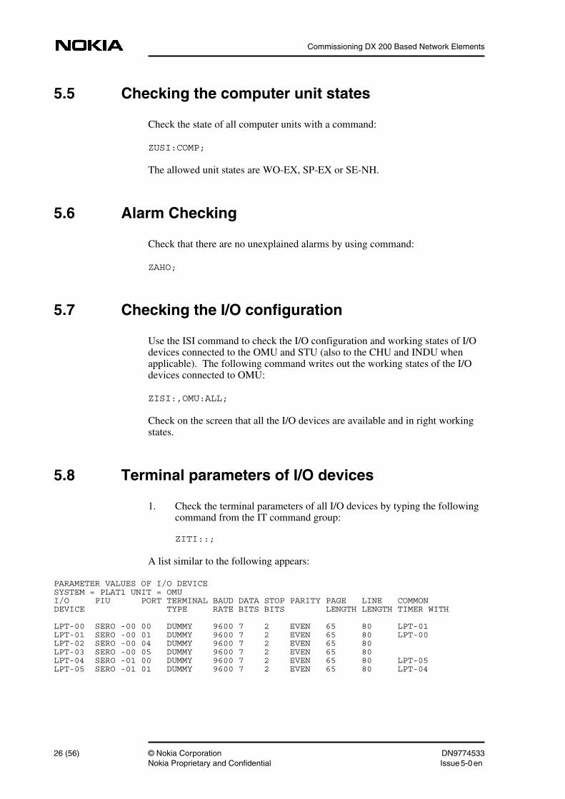
5.8 Terminal parameters of I/O devices
1. Check the terminal parameters of all I/O devices by typing the followingcommand from the IT command group:
ZITI::;
A list similar to the following appears:
PARAMETER VALUES OF I/O DEVICESYSTEM = PLAT1 UNIT = OMUI/O PIU PORT TERMINAL BAUD DATA STOP PARITY PAGE LINE COMMONDEVICE TYPE RATE BITS BITS LENGTH LENGTH TIMER WITH
LPT-00 SERO -00 00 DUMMY 9600 7 2 EVEN 65 80 LPT-01LPT-01 SERO -00 01 DUMMY 9600 7 2 EVEN 65 80 LPT-00LPT-02 SERO -00 04 DUMMY 9600 7 2 EVEN 65 80LPT-03 SERO -00 05 DUMMY 9600 7 2 EVEN 65 80LPT-04 SERO -01 00 DUMMY 9600 7 2 EVEN 65 80 LPT-05LPT-05 SERO -01 01 DUMMY 9600 7 2 EVEN 65 80 LPT-04
26 (56) © Nokia Corporation DN9774533Nokia Proprietary and Confidential Issue 5-0en
Inspecting user interfaces
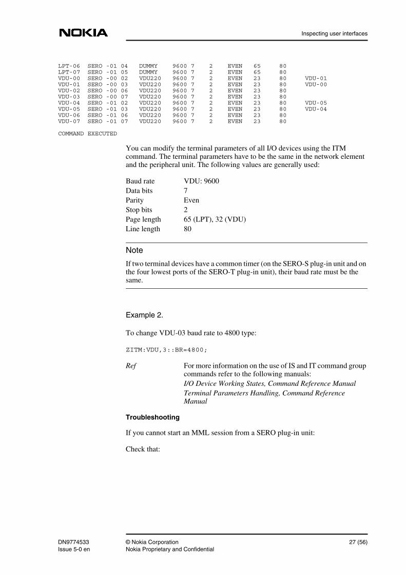
Note
LPT-06 SERO -01 04 DUMMY 9600 7 2 EVEN 65 80LPT-07 SERO -01 05 DUMMY 9600 7 2 EVEN 65 80VDU-00 SERO -00 02 VDU220 9600 7 2 EVEN 23 80 VDU-01VDU-01 SERO -00 03 VDU220 9600 7 2 EVEN 23 80 VDU-00VDU-02 SERO -00 06 VDU220 9600 7 2 EVEN 23 80VDU-03 SERO -00 07 VDU220 9600 7 2 EVEN 23 80VDU-04 SERO -01 02 VDU220 9600 7 2 EVEN 23 80 VDU-05VDU-05 SERO -01 03 VDU220 9600 7 2 EVEN 23 80 VDU-04VDU-06 SERO -01 06 VDU220 9600 7 2 EVEN 23 80VDU-07 SERO -01 07 VDU220 9600 7 2 EVEN 23 80
COMMAND EXECUTED
You can modify the terminal parameters of all I/O devices using the ITMcommand. The terminal parameters have to be the same in the network elementand the peripheral unit. The following values are generally used:
Baud rate VDU: 9600Data bits 7Parity EvenStop bits 2Page length 65 (LPT), 32 (VDU)Line length 80
If two terminal devices have a common timer (on the SERO-S plug-in unit and onthe four lowest ports of the SERO-T plug-in unit), their baud rate must be thesame.
Example 2.
To change VDU-03 baud rate to 4800 type:
ZITM:VDU,3::BR=4800;
Ref For more information on the use of IS and IT command groupcommands refer to the following manuals:I/O Device Working States, Command Reference ManualTerminal Parameters Handling, Command ReferenceManual
Troubleshooting
If you cannot start an MML session from a SERO plug-in unit:
Check that:
DN9774533 © Nokia Corporation 27 (56)Issue 5-0 en Nokia Proprietary and Confidential
Commissioning DX 200 Based Network Elements
• The VDU cable is correct, refer to the Site Documents and InstallationManual.
• The connection cable is intact, refer to the Print-outs of Starting Phases,Maintenance Manual.
• The strappings of the SERO plug-in unit are correct refer to the SiteDocuments.
• The VDU is in working order. Connect the female connector to the VDUand join the pins 2 and 3 of the free male connector to the strapping wire.Type any text on the keyboard. If the typed text is echoed on the display,the VDU is in order. If not, the VDU is faulty.
If you still cannot start a session, replace the SERO plug-in unit with a new oneand try again.
If I/O devices connected to SCSIF plug-in unit do not work, check theconfiguration of the terminal equipment connected to SCSIF plug-in unit usingthe ITI command. If needed, change the configuration.
Example 3.
To configure SCSIF ports 0 and 1 to be used by LPT-0 and VDU-0, type thefollowing commands:
ZITM:LPT,0:PT=SCSIF,PN=0:;
ZITM:VDU,0:PT=SCSIF,PN=1:;
5.9 Video display
Check the operation of all VDUs and VDU interfaces one by one.
1. Enter the ISI command to check the I/O configuration. The followingcommand writes out the working states of I/O devices connected to theOMU:
ZISI::ALL;
2. Connect a VDU to all VDU interfaces one by one. Use the ISI command tocheck that the working state changes from BL-SY to WO-ID.
3. Open an MML session from all the VDU interfaces.
Ref For more information on the use of IS command groupcommands, refer to the I/O Device Working States, CommandReference Manual.
28 (56) © Nokia Corporation DN9774533Nokia Proprietary and Confidential Issue 5-0en
Inspecting user interfaces
Troubleshooting
If you cannot get output from SERO ports check that:
• The strappings of the SERO plug-in units are correct, refer to the SiteDocuments.
• The VDU cable is correct, refer to the Site Documents and InstallationManual.
5.10 Line printer
Check the operation of all LPTs and LPT interfaces one by one.
1. Use the ISI command to check the state of each line printer. Use the LPTas output device.
ZISI::ALL:,LPT<nbr>;
2. Switch off the power of the printer. At the switch terminal check the stateof the printer using the ISI command. The state should be BL-SY.
3. Switch the printer back on. Check for state WO-ID.
4. To modify the line parameters of all I/O devices use the ITM command inthe same way as described in the section Video Display.
Troubleshooting
If print-outs are not produced:
1. Check that:
• The LPT cable is correct, refer to the Site Documents andInstallation Manual.
• The line parameters are correct, refer to the Recovery and UnitWorking State Administration, Maintenance Manualand TerminalParameters Handling, Command Reference Manual.
• The strappings of the SERO plug-in unit are correct, refer to the SiteDocuments.
2. If a printer connected to SCSIF plug-in unit does not work, check theconfiguration of SCSIF plug-in unit using the ITI command. If needed,change the configuration.
DN9774533 © Nokia Corporation 29 (56)Issue 5-0 en Nokia Proprietary and Confidential
Commissioning DX 200 Based Network Elements
Example 4.
To configure SCSIF port 0 to be used by LPT-10, type the followingcommand:
ZITM:LPT,10:PT=SCSIF,PN=0:;
5.11 Magnetic Tape Unit
To prepare a magnetic tape unit for use:
1. Create a magnetic tape unit with the following command from the WTcommand group:
WTU:<unit_name>,<unit_index>::<master_unit>;
Ref For more information on the use of WT commandgroup commands, refer to the following manuals:Equipment management, Command Reference ManualDiagnostics and testing, Maintenance Manual
2. Define the SCSI address data of the MTU.
Example 5.
The command for MTU-0 could be:
ZISK::MTU,0:0,4,0:;
3. Interrogate the SCSI address data of all the magnetic tape units:
ZISK::MTU;
The print-out is similar to the following:
/* IDENTIFY I/O DEVICE TYPE: MTU .... MAGNETIC TAPE UNIT */
ISK::MTU,0;
MTU- 0: SCSI BUS = 0, SCSI ID = 4, LUN = 0
COMMAND EXECUTED
4. Turn on the magnetic tape unit to check the unit's connections. Theworking state should automatically change from MI-SY to BL-SY, if allconnections are properly set (use the ISI command to check this).
5. Mount a magnetic tape reel.
30 (56) © Nokia Corporation DN9774533Nokia Proprietary and Confidential Issue 5-0en
Inspecting user interfaces
6. Load the tape according to the instructions on the MTU's front panel. Bringthe MTU on-line by pushing the on-line button on the MTU, check that thestate is WO-ID.
7. Use the IMP command to premark the magnetic tape:
ZIMP::MTU,0,C41A00,N,Y,ADM_SITE_1;
Where the tape name is the following (this is only an example on how toname magnetic tapes):
C41A00
C = Charging
41 = Area code number
A = Magnetic tape unit (A=0, B=1, E=4)
00 = Ordering number of a tape
Give the magnetic tape a name that describes the use of the tape. After premarkingthe magnetic tape, check that the state is WO-BU.
Ref For more information on the use of IS and IM command groupcommands refer to the following manuals:Magnetic Tape Handling, Operating ManualI/O Device Working States, Command Reference ManualMagnetic Tape Handling, Command Reference Manual
Troubleshooting
If there is no connection to magnetic tape units, check that:
1. The cables are correct and the MTU's SCSI ID is correctly strapped on theSCAD plug-in unit (C 23727), refer to the Site Documents and InstallationManual.
2. The formatter unit exists, refer to the Changing of Mass Memory Units,Maintenance Manual.
3. The SCSI BUS terminal resistors exist and are correctly installed. Place theterminal resistor at the MTU end of the cable, refer to the InstallationManual.
4. The program block TAPEDR has been created. Use the following serviceterminal command:
ZOH:F0;
An output similar to the following indicates that the TAPEDR programblock has been created (only the beginning of the output included here).
DN9774533 © Nokia Corporation 31 (56)Issue 5-0 en Nokia Proprietary and Confidential
Commissioning DX 200 Based Network Elements
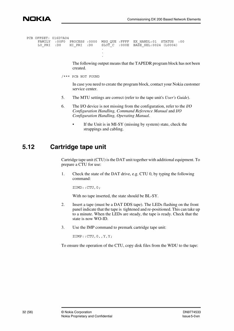
PCB OFFSET: 016D7A04 FAMILY :00F0 PROCESS :0000 MSG_QUE :FFFF EX_HANDL:01 STATUS :00 LO_PRI :D0 HI_PRI :D0 SLOT_C :000E BASE_SEL:0024 (L0004) . . .
The following output means that the TAPEDR program block has not beencreated.
/*** PCB NOT FOUND
In case you need to create the program block, contact your Nokia customerservice center.
5. The MTU settings are correct (refer to the tape unit's User's Guide).
6. The I/O device is not missing from the configuration, refer to the I/OConfiguration Handling, Command Reference Manual and I/OConfiguration Handling, Operating Manual.
• If the Unit is in MI-SY (missing by system) state, check thestrappings and cabling.
5.12 Cartridge tape unit
Cartridge tape unit (CTU) is the DAT unit together with additional equipment. Toprepare a CTU for use:
1. Check the state of the DAT drive, e.g. CTU 0, by typing the followingcommand:
ZIMD::CTU,0;
With no tape inserted, the state should be BL-SY.
2. Insert a tape (must be a DAT DDS tape). The LEDs flashing on the frontpanel indicate that the tape is tightened and re-positioned. This can take upto a minute. When the LEDs are steady, the tape is ready. Check that thestate is now WO-ID.
3. Use the IMP command to premark cartridge tape unit:
ZIMP::CTU,0,,Y,Y;
To ensure the operation of the CTU, copy disk files from the WDU to the tape:
32 (56) © Nokia Corporation DN9774533Nokia Proprietary and Confidential Issue 5-0en
Inspecting user interfaces
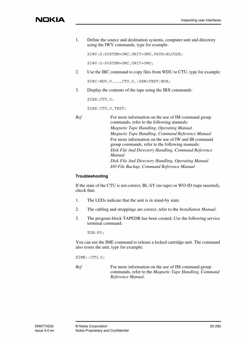
1. Define the source and destination systems, computer unit and directoryusing the IWY commands, type for example:
ZIWY:S:SYSTEM=OMC,UNIT=OMU,PATH=BLCODE;
ZIWY:D:SYSTEM=OMC,UNIT=OMU;
2. Use the IBC command to copy files from WDU to CTU, type for example:
ZIBC:WDU,0,,,,CTU,0,:DSN=TEST:NOA;
3. Display the contents of the tape using the IBX commands:
ZIBX:CTU,0;
ZIBX:CTU,0,TEST;
Ref For more information on the use of IM command groupcommands, refer to the following manuals:Magnetic Tape Handling, Operating ManualMagnetic Tape Handling, Command Reference ManualFor more information on the use of IW and IB commandgroup commands, refer to the following manuals:Disk File And Directory Handling, Command ReferenceManualDisk File And Directory Handling, Operating ManualI/O File Backup, Command Reference Manual
Troubleshooting
If the state of the CTU is not correct, BL-SY (no tape) or WO-ID (tape inserted),check that:
1. The LEDs indicate that the unit is in stand-by state.
2. The cabling and strappings are correct, refer to the Installation Manual.
3. The program block TAPEDR has been created. Use the following serviceterminal command:
ZOH:F0;
You can use the IME command to release a locked cartridge unit. The commandalso resets the unit, type for example:
ZIME::CTU,0;
Ref For more information on the use of IM command groupcommands, refer to the Magnetic Tape Handling, CommandReference Manual.
DN9774533 © Nokia Corporation 33 (56)Issue 5-0 en Nokia Proprietary and Confidential
Commissioning DX 200 Based Network Elements
5.13 Print-outs during commissioning
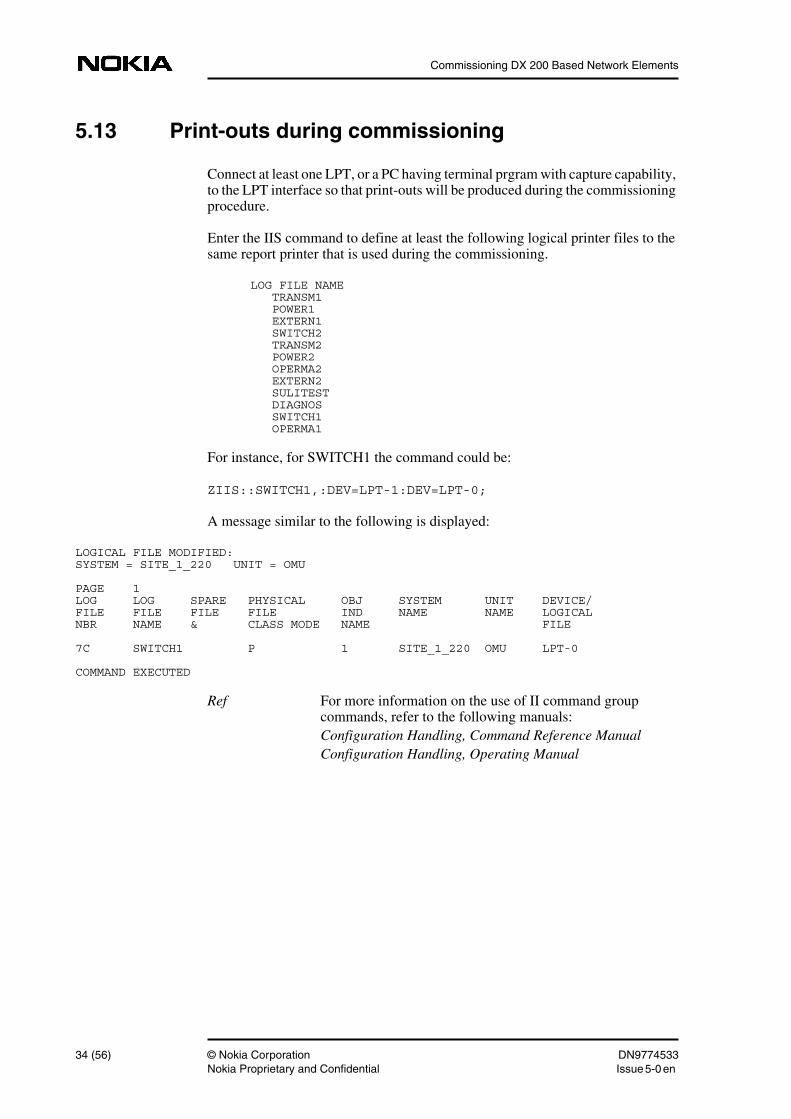
Connect at least one LPT, or a PC having terminal prgram with capture capability,to the LPT interface so that print-outs will be produced during the commissioningprocedure.
Enter the IIS command to define at least the following logical printer files to thesame report printer that is used during the commissioning.
LOG FILE NAME TRANSM1 POWER1 EXTERN1 SWITCH2 TRANSM2 POWER2 OPERMA2 EXTERN2 SULITEST DIAGNOS SWITCH1 OPERMA1
For instance, for SWITCH1 the command could be:
ZIIS::SWITCH1,:DEV=LPT-1:DEV=LPT-0;
A message similar to the following is displayed:
LOGICAL FILE MODIFIED:SYSTEM = SITE_1_220 UNIT = OMU
PAGE 1LOG LOG SPARE PHYSICAL OBJ SYSTEM UNIT DEVICE/FILE FILE FILE FILE IND NAME NAME LOGICALNBR NAME & CLASS MODE NAME FILE
7C SWITCH1 P 1 SITE_1_220 OMU LPT-0
COMMAND EXECUTED
Ref For more information on the use of II command groupcommands, refer to the following manuals:Configuration Handling, Command Reference ManualConfiguration Handling, Operating Manual
34 (56) © Nokia Corporation DN9774533Nokia Proprietary and Confidential Issue 5-0en
Hardware database configuration
6 Hardware database configurationThis chapter explains how to check the configuration of the hardware database.These checks are worth special attention because any errors in the equipping ofthe exchange in the hardware database are quite arduous to correct. Check thatyou have created cartridges to correct locations with correct parameters for alarmand power.
If you discover errors at a later stage, you have to delete the plug-in units, unitsand cartridges before you can create them again with the correct parameters. Forthe exchange terminal unit (ET) in particular, these operations are very hard to doafter the routing has been created, because you must also delete the routing beforedeleting plug-in units, units and cartridges.
6.1 References
1. Site Documents
2. Equipment Management, Command Reference Manual
3. Hardware Configuration Management, Operating Manual
4. Unit Connections Handling, Command Reference Manual
6.2 Checking the hardware database
6.2.1 Checking the cartridges
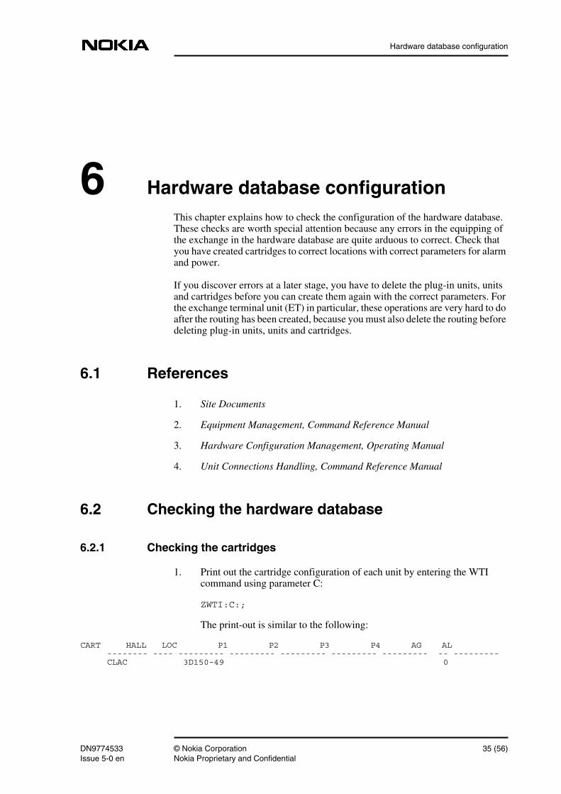
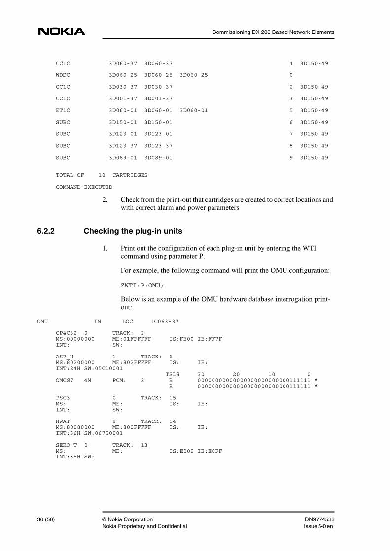
1. Print out the cartridge configuration of each unit by entering the WTIcommand using parameter C:
ZWTI:C:;
The print-out is similar to the following:
CART HALL LOC P1 P2 P3 P4 AG AL-------- ---- --------- --------- --------- --------- --------- -- ---------CLAC 3D150-49 0
DN9774533 © Nokia Corporation 35 (56)Issue 5-0 en Nokia Proprietary and Confidential
Commissioning DX 200 Based Network Elements
CC1C 3D060-37 3D060-37 4 3D150-49
WDDC 3D060-25 3D060-25 3D060-25 0
CC1C 3D030-37 3D030-37 2 3D150-49
CC1C 3D001-37 3D001-37 3 3D150-49
ET1C 3D060-01 3D060-01 3D060-01 5 3D150-49
SUBC 3D150-01 3D150-01 6 3D150-49
SUBC 3D123-01 3D123-01 7 3D150-49
SUBC 3D123-37 3D123-37 8 3D150-49
SUBC 3D089-01 3D089-01 9 3D150-49
TOTAL OF 10 CARTRIDGES
COMMAND EXECUTED
2. Check from the print-out that cartridges are created to correct locations andwith correct alarm and power parameters
6.2.2 Checking the plug-in units
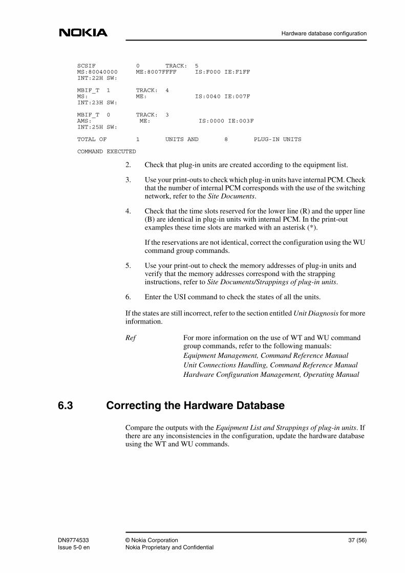
1. Print out the configuration of each plug-in unit by entering the WTIcommand using parameter P.
For example, the following command will print the OMU configuration:
ZWTI:P:OMU;
Below is an example of the OMU hardware database interrogation print-out:
OMU IN LOC 1C063-37
CP4C32 0 TRACK: 2MS:00000000 ME:01FFFFFF IS:FE00 IE:FF7FINT: SW:
AS7_U 1 TRACK: 6MS:80200000 ME:802FFFFF IS: IE:INT:24H SW:05C10001 TSLS 30 20 10 0OMCS7 4M PCM: 2 B 00000000000000000000000000111111 * R 00000000000000000000000000111111 *
PSC3 0 TRACK: 15MS: ME: IS: IE:INT: SW:
HWAT 9 TRACK: 14MS:80080000 ME:800FFFFF IS: IE:INT:36H SW:06750001
SERO_T 0 TRACK: 13MS: ME: IS:E000 IE:E0FFINT:35H SW:
36 (56) © Nokia Corporation DN9774533Nokia Proprietary and Confidential Issue 5-0en
Hardware database configuration
SCSIF 0 TRACK: 5MS:80040000 ME:8007FFFF IS:F000 IE:F1FFINT:22H SW:
MBIF_T 1 TRACK: 4MS: ME: IS:0040 IE:007FINT:23H SW:
MBIF_T 0 TRACK: 3AMS: ME: IS:0000 IE:003FINT:25H SW:
TOTAL OF 1 UNITS AND 8 PLUG-IN UNITS
COMMAND EXECUTED
2. Check that plug-in units are created according to the equipment list.
3. Use your print-outs to check which plug-in units have internal PCM. Checkthat the number of internal PCM corresponds with the use of the switchingnetwork, refer to the Site Documents.
4. Check that the time slots reserved for the lower line (R) and the upper line(B) are identical in plug-in units with internal PCM. In the print-outexamples these time slots are marked with an asterisk (*).
If the reservations are not identical, correct the configuration using the WUcommand group commands.
5. Use your print-out to check the memory addresses of plug-in units andverify that the memory addresses correspond with the strappinginstructions, refer to Site Documents/Strappings of plug-in units.
6. Enter the USI command to check the states of all the units.
If the states are still incorrect, refer to the section entitled Unit Diagnosis for moreinformation.
Ref For more information on the use of WT and WU commandgroup commands, refer to the following manuals:Equipment Management, Command Reference ManualUnit Connections Handling, Command Reference ManualHardware Configuration Management, Operating Manual
6.3 Correcting the Hardware Database
Compare the outputs with the Equipment List and Strappings of plug-in units. Ifthere are any inconsistencies in the configuration, update the hardware databaseusing the WT and WU commands.
DN9774533 © Nokia Corporation 37 (56)Issue 5-0 en Nokia Proprietary and Confidential
Commissioning DX 200 Based Network Elements
Subscriber modules reserve DP positions from the exchange in the same order asthe modules are created. If you notice that a subscriber module is missing fromthe configuration and you want to have the DP positions arranged in accordancewith the module order. Delete the created modules from the missing moduleonwards and create the modules again starting from the missing module.
LIA10/LIA16 plug-in units reserve DP positions from the subscriber module inthe same order as LIA10s/LIA16s are created. If you notice that a LIA10/LIA16plug-in unit is missing from the subscriber module configuration and you want tohave the DP positions arranged in accordance with the plug-in unit order. Deletethe created LIA10s/LIA16s from the missing plug-in unit onwards and create theplug-in units again starting from the missing LIA10/LIA16.
38 (56) © Nokia Corporation DN9774533Nokia Proprietary and Confidential Issue 5-0en
Inspecting the maintenance system
7 Inspecting the maintenance systemThis chapter explains how to inspect the maintenance system using differentchecks, diagnoses and measurements. The maintenance system needs to beinspected to ensure the reliable operation of the exchange and to make sure thatsupervision, alarm and recovery functions work properly.
7.1 References
• Circuit Group Handling, Operating Manual
• Circuit Group Handling, Command Reference Manual
• Internal Routing States, Command Reference Manual
• Equipment Management, Command Reference Manual
• Hardware Configuration Management, Operating Manual
• Unit Connections Handling, Command Reference Manual
• Working State and Restart Handling, Command Reference Manual
• Recovery and Unit Working State Administration, Maintenance Manual
• Diagnostics and Testing, Maintenance Manual
• Diagnostics Handling, Command Reference Manual
• Wired Alarm Connections Handling, Operating Manual
• Instructions for Engineering
• I/O Configuration Handling, Command Reference Manual
• I/O Configuration Handling, Operating Manual
• Installation Manual
• Instructions for Replacing Plug-in Units, Maintenance Manual
• Lamp Panel Handling, Command Reference Manual
DN9774533 © Nokia Corporation 39 (56)Issue 5-0 en Nokia Proprietary and Confidential
Commissioning DX 200 Based Network Elements
• Alarm Administration, Maintenance Manual
• Subscriber Measurement Configuration, Command Reference Manual
• Subscriber Measurement Configuration, Maintenance Manual
• Subscriber Identification, Command Reference Manual
• Subscriber Facilities, Command Reference Manual
• Subscriber Number Analysis Handling, Command Reference Manual
• Subscriber Line Routine Measurement, Command Reference Manual
• Buffered Report Output Handling, Command Reference Manual
• Subscriber Line Routine Measurement, Maintenance Manual
• Alarm History Handling, Command Reference Manual
• Led Indicators of Plug-in Units, Maintenance Manual
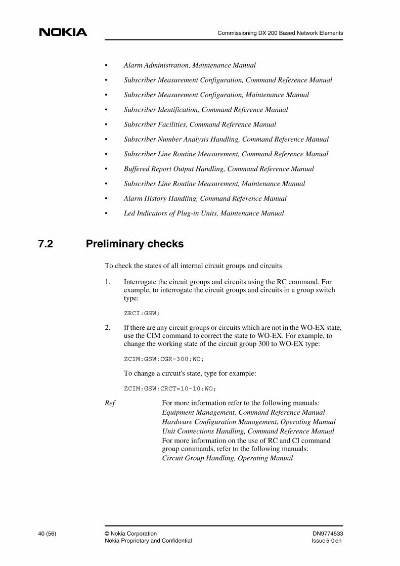
7.2 Preliminary checks
To check the states of all internal circuit groups and circuits
1. Interrogate the circuit groups and circuits using the RC command. Forexample, to interrogate the circuit groups and circuits in a group switchtype:
ZRCI:GSW;
2. If there are any circuit groups or circuits which are not in the WO-EX state,use the CIM command to correct the state to WO-EX. For example, tochange the working state of the circuit group 300 to WO-EX type:
ZCIM:GSW:CGR=300:WO;
To change a circuit's state, type for example:
ZCIM:GSW:CRCT=10-10:WO;
Ref For more information refer to the following manuals:Equipment Management, Command Reference ManualHardware Configuration Management, Operating ManualUnit Connections Handling, Command Reference ManualFor more information on the use of RC and CI commandgroup commands, refer to the following manuals:Circuit Group Handling, Operating Manual
40 (56) © Nokia Corporation DN9774533Nokia Proprietary and Confidential Issue 5-0en
Inspecting the maintenance system
Note
Circuit Group Handling, Command Reference ManualInternal Routing States, Command Reference Manual
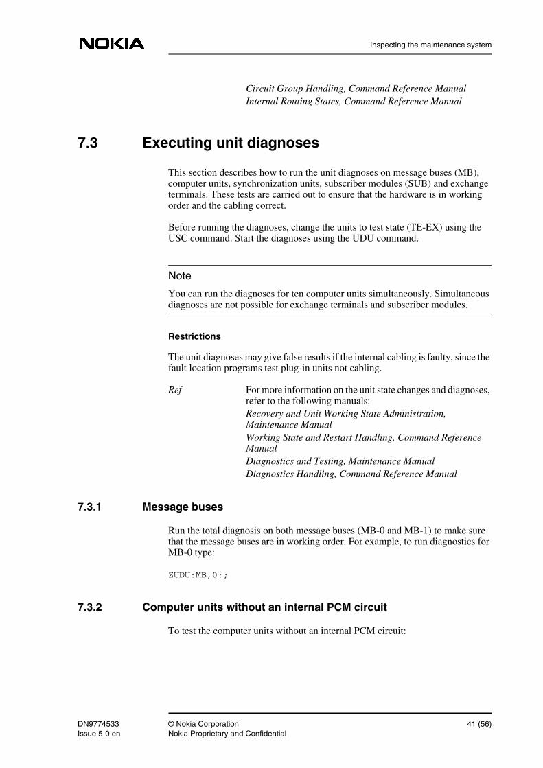
7.3 Executing unit diagnoses
This section describes how to run the unit diagnoses on message buses (MB),computer units, synchronization units, subscriber modules (SUB) and exchangeterminals. These tests are carried out to ensure that the hardware is in workingorder and the cabling correct.
Before running the diagnoses, change the units to test state (TE-EX) using theUSC command. Start the diagnoses using the UDU command.
You can run the diagnoses for ten computer units simultaneously. Simultaneousdiagnoses are not possible for exchange terminals and subscriber modules.
Restrictions
The unit diagnoses may give false results if the internal cabling is faulty, since thefault location programs test plug-in units not cabling.
Ref For more information on the unit state changes and diagnoses,refer to the following manuals:Recovery and Unit Working State Administration,Maintenance ManualWorking State and Restart Handling, Command ReferenceManualDiagnostics and Testing, Maintenance ManualDiagnostics Handling, Command Reference Manual
7.3.1 Message buses
Run the total diagnosis on both message buses (MB-0 and MB-1) to make surethat the message buses are in working order. For example, to run diagnostics forMB-0 type:
ZUDU:MB,0:;
7.3.2 Computer units without an internal PCM circuit
To test the computer units without an internal PCM circuit:
DN9774533 © Nokia Corporation 41 (56)Issue 5-0 en Nokia Proprietary and Confidential
Commissioning DX 200 Based Network Elements
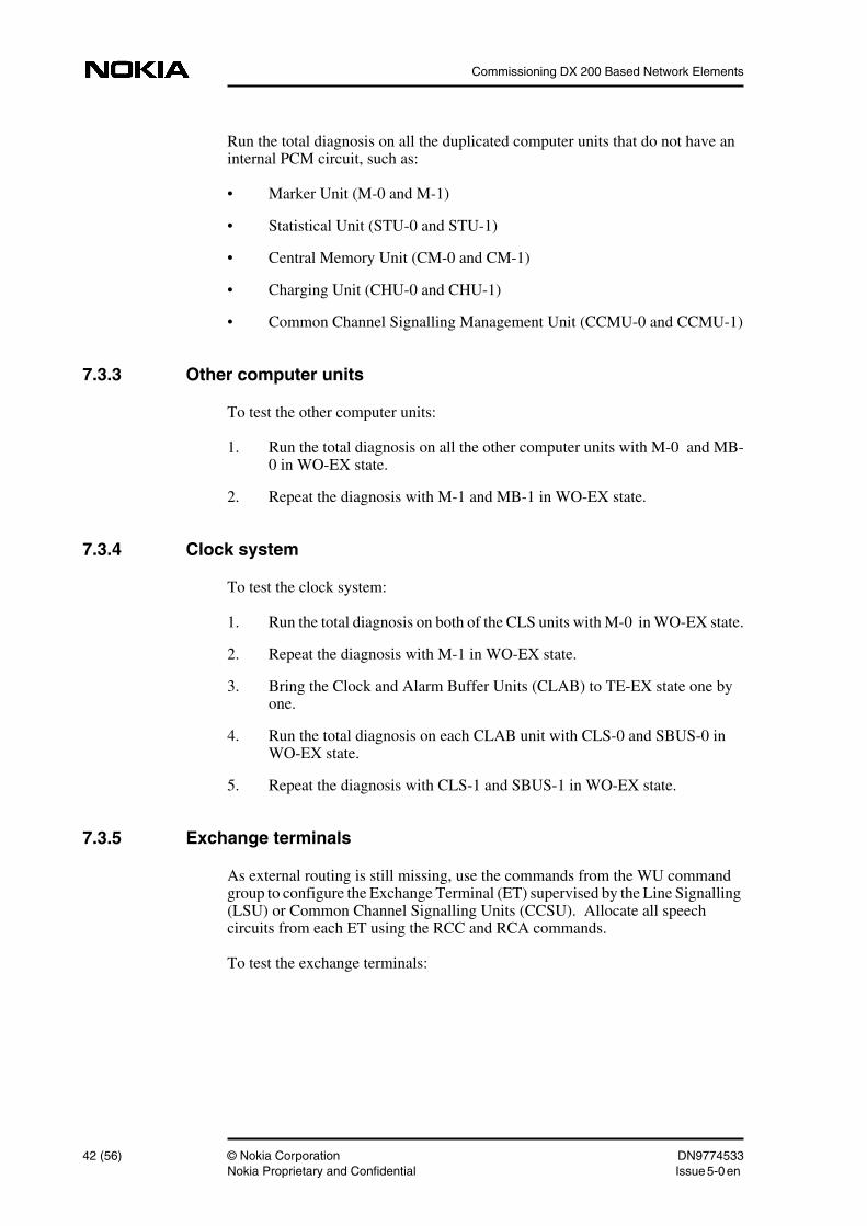
Run the total diagnosis on all the duplicated computer units that do not have aninternal PCM circuit, such as:
• Marker Unit (M-0 and M-1)
• Statistical Unit (STU-0 and STU-1)
• Central Memory Unit (CM-0 and CM-1)
• Charging Unit (CHU-0 and CHU-1)
• Common Channel Signalling Management Unit (CCMU-0 and CCMU-1)
7.3.3 Other computer units
To test the other computer units:
1. Run the total diagnosis on all the other computer units with M-0 and MB-0 in WO-EX state.
2. Repeat the diagnosis with M-1 and MB-1 in WO-EX state.
7.3.4 Clock system
To test the clock system:
1. Run the total diagnosis on both of the CLS units with M-0 in WO-EX state.
2. Repeat the diagnosis with M-1 in WO-EX state.
3. Bring the Clock and Alarm Buffer Units (CLAB) to TE-EX state one byone.
4. Run the total diagnosis on each CLAB unit with CLS-0 and SBUS-0 inWO-EX state.
5. Repeat the diagnosis with CLS-1 and SBUS-1 in WO-EX state.
7.3.5 Exchange terminals
As external routing is still missing, use the commands from the WU commandgroup to configure the Exchange Terminal (ET) supervised by the Line Signalling(LSU) or Common Channel Signalling Units (CCSU). Allocate all speechcircuits from each ET using the RCC and RCA commands.
To test the exchange terminals:
42 (56) © Nokia Corporation DN9774533Nokia Proprietary and Confidential Issue 5-0en
Inspecting the maintenance system
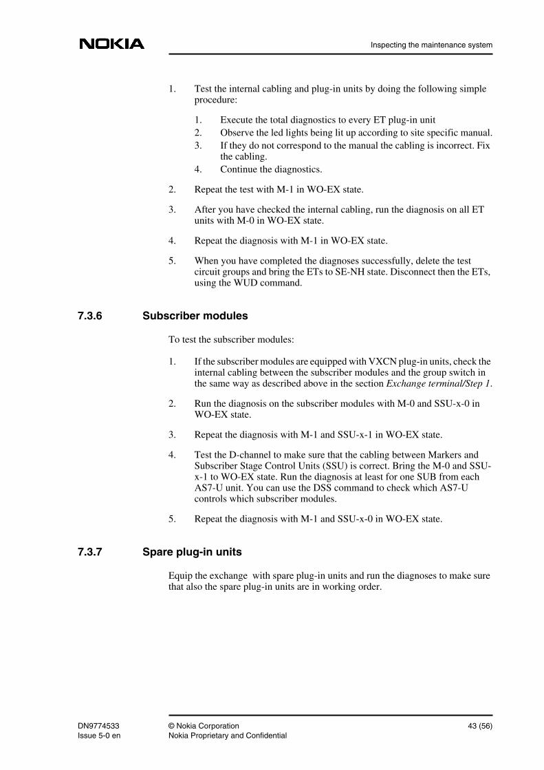
1. Test the internal cabling and plug-in units by doing the following simpleprocedure:
1. Execute the total diagnostics to every ET plug-in unit2. Observe the led lights being lit up according to site specific manual.3. If they do not correspond to the manual the cabling is incorrect. Fix
the cabling.4. Continue the diagnostics.
2. Repeat the test with M-1 in WO-EX state.
3. After you have checked the internal cabling, run the diagnosis on all ETunits with M-0 in WO-EX state.
4. Repeat the diagnosis with M-1 in WO-EX state.
5. When you have completed the diagnoses successfully, delete the testcircuit groups and bring the ETs to SE-NH state. Disconnect then the ETs,using the WUD command.
7.3.6 Subscriber modules
To test the subscriber modules:
1. If the subscriber modules are equipped with VXCN plug-in units, check theinternal cabling between the subscriber modules and the group switch inthe same way as described above in the section Exchange terminal/Step 1.
2. Run the diagnosis on the subscriber modules with M-0 and SSU-x-0 inWO-EX state.
3. Repeat the diagnosis with M-1 and SSU-x-1 in WO-EX state.
4. Test the D-channel to make sure that the cabling between Markers andSubscriber Stage Control Units (SSU) is correct. Bring the M-0 and SSU-x-1 to WO-EX state. Run the diagnosis at least for one SUB from eachAS7-U unit. You can use the DSS command to check which AS7-Ucontrols which subscriber modules.
5. Repeat the diagnosis with M-1 and SSU-x-0 in WO-EX state.
7.3.7 Spare plug-in units
Equip the exchange with spare plug-in units and run the diagnoses to make surethat also the spare plug-in units are in working order.
DN9774533 © Nokia Corporation 43 (56)Issue 5-0 en Nokia Proprietary and Confidential
Commissioning DX 200 Based Network Elements
7.4 Wired alarms
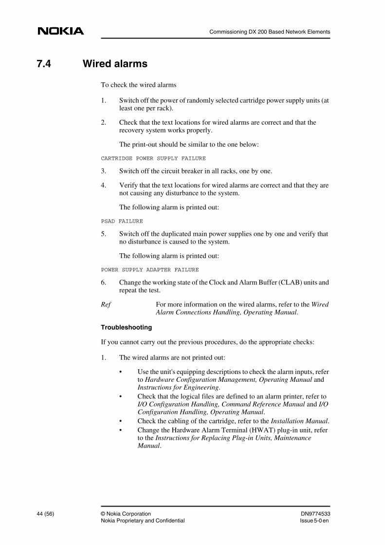
To check the wired alarms
1. Switch off the power of randomly selected cartridge power supply units (atleast one per rack).
2. Check that the text locations for wired alarms are correct and that therecovery system works properly.
The print-out should be similar to the one below:
CARTRIDGE POWER SUPPLY FAILURE
3. Switch off the circuit breaker in all racks, one by one.
4. Verify that the text locations for wired alarms are correct and that they arenot causing any disturbance to the system.
The following alarm is printed out:
PSAD FAILURE
5. Switch off the duplicated main power supplies one by one and verify thatno disturbance is caused to the system.
The following alarm is printed out:
POWER SUPPLY ADAPTER FAILURE
6. Change the working state of the Clock and Alarm Buffer (CLAB) units andrepeat the test.
Ref For more information on the wired alarms, refer to the WiredAlarm Connections Handling, Operating Manual.
Troubleshooting
If you cannot carry out the previous procedures, do the appropriate checks:
1. The wired alarms are not printed out:
• Use the unit's equipping descriptions to check the alarm inputs, referto Hardware Configuration Management, Operating Manual andInstructions for Engineering.
• Check that the logical files are defined to an alarm printer, refer toI/O Configuration Handling, Command Reference Manual and I/OConfiguration Handling, Operating Manual.
• Check the cabling of the cartridge, refer to the Installation Manual.• Change the Hardware Alarm Terminal (HWAT) plug-in unit, refer
to the Instructions for Replacing Plug-in Units, MaintenanceManual.
44 (56) © Nokia Corporation DN9774533Nokia Proprietary and Confidential Issue 5-0en
Inspecting the maintenance system
2. The alarm text and cartridge location differ:
• Check the hardware database configuration of the cartridge, refer tothe chapter Hardware Database Configuration.
3. The wired alarms are printed out with only one CLAB unit.
• Change the CLAB plug-in unit, refer to the Instructions forReplacing Plug-in Units, Maintenance Manual.
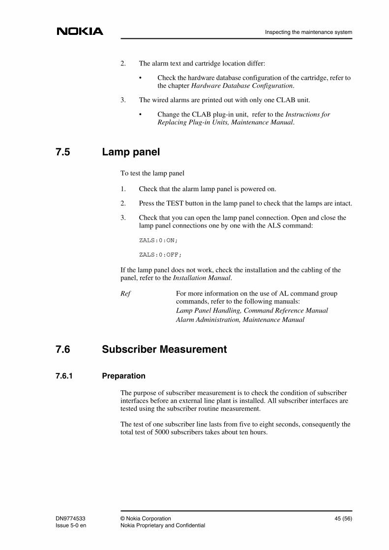
7.5 Lamp panel
To test the lamp panel
1. Check that the alarm lamp panel is powered on.
2. Press the TEST button in the lamp panel to check that the lamps are intact.
3. Check that you can open the lamp panel connection. Open and close thelamp panel connections one by one with the ALS command:
ZALS:0:ON;
ZALS:0:OFF;
If the lamp panel does not work, check the installation and the cabling of thepanel, refer to the Installation Manual.
Ref For more information on the use of AL command groupcommands, refer to the following manuals:Lamp Panel Handling, Command Reference ManualAlarm Administration, Maintenance Manual
7.6 Subscriber Measurement
7.6.1 Preparation
The purpose of subscriber measurement is to check the condition of subscriberinterfaces before an external line plant is installed. All subscriber interfaces aretested using the subscriber routine measurement.
The test of one subscriber line lasts from five to eight seconds, consequently thetotal test of 5000 subscribers takes about ten hours.
DN9774533 © Nokia Corporation 45 (56)Issue 5-0 en Nokia Proprietary and Confidential
Commissioning DX 200 Based Network Elements
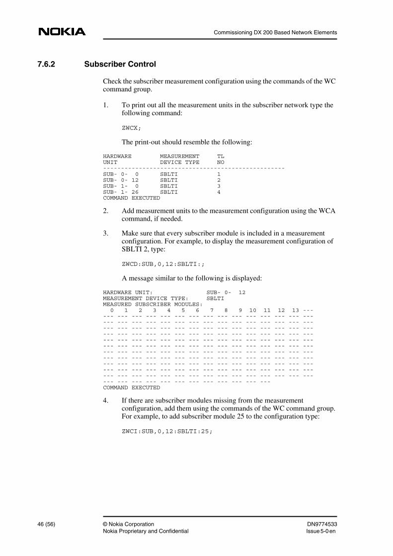
7.6.2 Subscriber Control
Check the subscriber measurement configuration using the commands of the WCcommand group.
1. To print out all the measurement units in the subscriber network type thefollowing command:
ZWCX;
The print-out should resemble the following:
HARDWARE MEASUREMENT TLUNIT DEVICE TYPE NO---------------------------------------------------SUB- 0- 0 SBLTI 1SUB- 0- 12 SBLTI 2SUB- 1- 0 SBLTI 3SUB- 1- 26 SBLTI 4COMMAND EXECUTED
2. Add measurement units to the measurement configuration using the WCAcommand, if needed.
3. Make sure that every subscriber module is included in a measurementconfiguration. For example, to display the measurement configuration ofSBLTI 2, type:
ZWCD:SUB,0,12:SBLTI:;
A message similar to the following is displayed:
HARDWARE UNIT: SUB- 0- 12MEASUREMENT DEVICE TYPE: SBLTIMEASURED SUBSCRIBER MODULES: 0 1 2 3 4 5 6 7 8 9 10 11 12 13 ------ --- --- --- --- --- --- --- --- --- --- --- --- --- ------ --- --- --- --- --- --- --- --- --- --- --- --- --- ------ --- --- --- --- --- --- --- --- --- --- --- --- --- ------ --- --- --- --- --- --- --- --- --- --- --- --- --- ------ --- --- --- --- --- --- --- --- --- --- --- --- --- ------ --- --- --- --- --- --- --- --- --- --- --- --- --- ------ --- --- --- --- --- --- --- --- --- --- --- --- --- ------ --- --- --- --- --- --- --- --- --- --- --- --- --- ------ --- --- --- --- --- --- --- --- --- --- --- --- --- ------ --- --- --- --- --- --- --- --- --- --- --- --- --- ------ --- --- --- --- --- --- --- --- --- --- --- --- --- ------ --- --- --- --- --- --- --- --- --- --- ---COMMAND EXECUTED
4. If there are subscriber modules missing from the measurementconfiguration, add them using the commands of the WC command group.For example, to add subscriber module 25 to the configuration type:
ZWCI:SUB,0,12:SBLTI:25;
46 (56) © Nokia Corporation DN9774533Nokia Proprietary and Confidential Issue 5-0en
Inspecting the maintenance system
Ref For more information on the use of WC command groupcommands, refer to the following manuals:Subscriber Measurement Configuration, CommandReference ManualSubscriber Measurement Configuration, MaintenanceManual
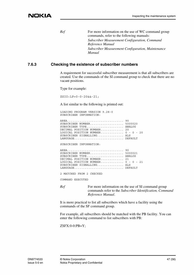
7.6.3 Checking the existence of subscriber numbers
A requirement for successful subscriber measurement is that all subscribers arecreated. Use the commands of the SI command group to check that there are novacant positions.
Type for example:
ZSIO:LP=0-0-20&&-21;
A list similar to the following is printed out:
LOADING PROGRAM VERSION 9.28-0SUBSCRIBER INFORMATION:
AREA................................ 90SUBSCRIBER NUMBER................... 5000020SUBSCRIBER TYPE..................... ANALOGDECIMAL POSITION NUMBER............. 20LOGICAL POSITION NUMBER............. 0 - 0 - 20SUBSCRIBER SIGNALLING............... ALSLANGUAGE............................ DEFAULT
SUBSCRIBER INFORMATION:
AREA................................ 90SUBSCRIBER NUMBER................... 5000021SUBSCRIBER TYPE..................... ANALOGDECIMAL POSITION NUMBER............. 21LOGICAL POSITION NUMBER............. 0 - 0 - 21SUBSCRIBER SIGNALLING............... ALSLANGUAGE............................ DEFAULT
2 MATCHED FROM 2 CHECKED
COMMAND EXECUTED
Ref For more information on the use of SI command groupcommands refer to the Subscriber Identification, CommandReference Manual.
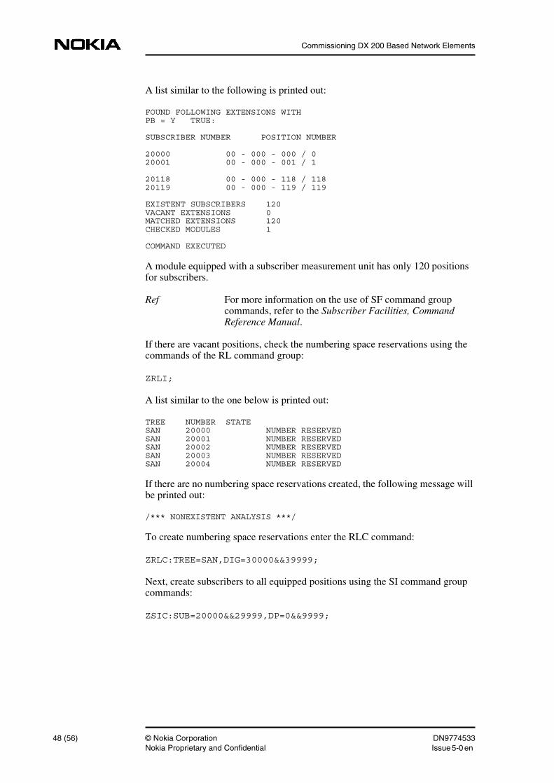
It is more practical to list all subscribers which have a facility using thecommands of the SF command group.
For example, all subscribers should be matched with the PB facility. You canenter the following command to list subscribers with PB:
ZSFX:0-0:PB=Y;
DN9774533 © Nokia Corporation 47 (56)Issue 5-0 en Nokia Proprietary and Confidential
Commissioning DX 200 Based Network Elements
A list similar to the following is printed out:
FOUND FOLLOWING EXTENSIONS WITHPB = Y TRUE:
SUBSCRIBER NUMBER POSITION NUMBER
20000 00 - 000 - 000 / 020001 00 - 000 - 001 / 1
20118 00 - 000 - 118 / 11820119 00 - 000 - 119 / 119
EXISTENT SUBSCRIBERS 120VACANT EXTENSIONS 0MATCHED EXTENSIONS 120CHECKED MODULES 1
COMMAND EXECUTED
A module equipped with a subscriber measurement unit has only 120 positionsfor subscribers.
Ref For more information on the use of SF command groupcommands, refer to the Subscriber Facilities, CommandReference Manual.
If there are vacant positions, check the numbering space reservations using thecommands of the RL command group:
ZRLI;
A list similar to the one below is printed out:
TREE NUMBER STATESAN 20000 NUMBER RESERVEDSAN 20001 NUMBER RESERVEDSAN 20002 NUMBER RESERVEDSAN 20003 NUMBER RESERVEDSAN 20004 NUMBER RESERVED
If there are no numbering space reservations created, the following message willbe printed out:
/*** NONEXISTENT ANALYSIS ***/
To create numbering space reservations enter the RLC command:
ZRLC:TREE=SAN,DIG=30000&&39999;
Next, create subscribers to all equipped positions using the SI command groupcommands:
ZSIC:SUB=20000&&29999,DP=0&&9999;
48 (56) © Nokia Corporation DN9774533Nokia Proprietary and Confidential Issue 5-0en
Inspecting the maintenance system
Note
Ref For more information on the use of RL command groupcommands, refer to the Subscriber Number AnalysisHandling, Command Reference Manual.
7.6.4 Routine Measurement
To run a routine measurement.
Since the routine measurement uses both hard disks, make sure that disks are incorrect working state and that both disks contain an ASWDIR directory. TheROTEST process creates its own directories in the ASWDIR directory, e.g. aREPORT directory for COM00.REP and SLR00.REP, and ring buffer files.
You can, for instance, create directories using service terminal commands:
ZMCD:W0-/A/ASWDIR,65
ZMCD:W1-/A/ASWDIR,65
1. Check that there is an ASWDIR directory on both hard disks.
2. Create the routine measurement by entering the URC command.
For example, to measure the lines of group number 15 (possible values 0-15) every day between 8.30 p.m. and 7.00 a.m., type the followingcommand:
ZURC:MEAG=15:START=20-30,STOP=7-00:WEEK1=MON&&SUN;
When the measurement is completed, a measurement report is written out.
If the routine measurement fails, check the condition of faulty subscriberinterfaces again as described in the section Line Measurement.
Ref For more information on the use of UR command groupcommands, refer to the Subscriber Line RoutineMeasurement, Command Reference Manual.
Define a subset for subscriber line measurement
You can, for example, perform all measurements on the subscriber lines and printout the information on all the measured lines. In the example below, themeasurement group number is 10, the starting time of the measurement 8.30 p.m.,and no concurrently starting measurements have been defined for themeasurement group (i.e. you can omit the symbol for the alternativemeasurement).
DN9774533 © Nokia Corporation 49 (56)Issue 5-0 en Nokia Proprietary and Confidential
Commissioning DX 200 Based Network Elements
ZURM:MEAG=10,START=20-30::OUT=ALL;
Define the subscriber hybrid test
You can define the subscriber hybrid test so that all the measured subscriber lineinterfaces will be printed out. In this example the measurement group number is10, the starting time 8.30 p.m., and no concurrently starting measurements havebeen defined for the measurement group (i.e. you can omit the alternativesymbol).
ZURH:MEAG=10,START=20-30:OUT=ALL;
7.6.5 Printing the routine measurement results
Print routine measurement results to a logical file using the UA commands.
1. Interrogate the identification data of existing buffered reports forsubscriber lines using the following UAI command. The identification datacontains measurement starting times and report group numbers needed inthe print command.
ZUAI:TYPE=SLR;
2. The results will be printed to a logical file. Make sure that the logical fileyou are using in the print command is connected to correct I/O device.
3. Print the results to a logical file (NAME=<name of the logical file>) usingcorrect start time and report group number:
ZUAP:TYPE=SLR:GROUP=7,START=20-30:NAME=PRINTQUE10;
Ref For more information on the use of UA commands, refer tothe Buffered Report Output Handling, Command ReferenceManual.
7.6.6 Line measurement
Measure subscriber lines using the UL commands.
Forced control does not start the measurement unless the subscriber status is free.The subscriber may have a semipermanent connection or the status is either busyor ringing - in this case an error message is printed out.
50 (56) © Nokia Corporation DN9774533Nokia Proprietary and Confidential Issue 5-0en
Inspecting the maintenance system
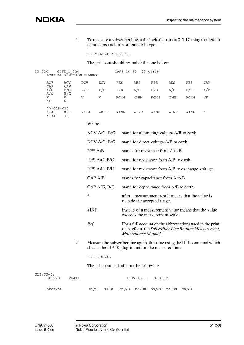
1. To measure a subscriber line at the logical position 0-5-17 using the defaultparameters (=all measurements), type:
ZULM:LP=0-5-17:::;
The print-out should resemble the one below:
DX 220 SITE_1_220 1995-10-10 09:44:48LOGICAL POSITION NUMBER
ACV ACV DCV DCV RES RES RES RES RES CAPCAP CAPA/G B/G A/G B/G A/B A/G B/G A/U B/U A/BA/G B/GV V V V KOHM KOHM KOHM KOHM KOHM NFNF NF
00-005-0170.0 0.0 -0.0 -0.0 +INF +INF +INF +INF +INF 2* 24 18
Where:
ACV A/G, B/G stand for alternating voltage A/B to earth.
DCV A/G, B/G stand for direct voltage A/B to earth.
RES A/B stands for resistance from A to B.
RES A/G, B/G stand for resistance from A/B to earth.
RES A/U, B/U stand for resistance from A/B to exchange voltage.
CAP A/B stands for capacitance from A to B.
CAP A/G, B/G stand for capacitance from A/B to earth.
* after a measurement result means that the value isoutside the accepted range.
+INF instead of a measurement value means that the valueexceeds the measurement scale.
Ref For a full account on the abbreviations used in the print-outs refer to the Subscriber Line Routine Measurement,Maintenance Manual.
2. Measure the subscriber line again, this time using the ULI command whichchecks the LIA10 plug-in unit on the measured line:
ZULI:DP=0;
The print-out is similar to the following:
ULI:DP=0;DX 220 PLAT1 1995-10-10 16:13:25
DECIMAL P1/V P2/V D1/dB D2/dB D3/dB D4/dB D5/dB
DN9774533 © Nokia Corporation 51 (56)Issue 5-0 en Nokia Proprietary and Confidential
Commissioning DX 200 Based Network Elements
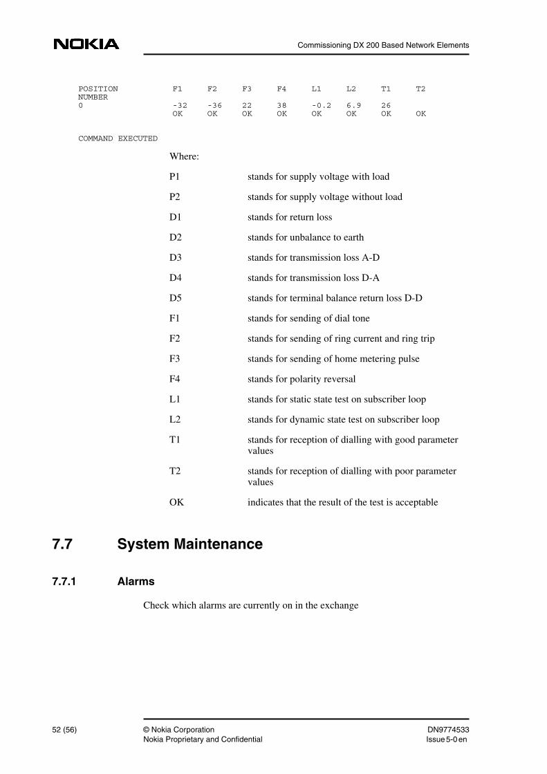
POSITION F1 F2 F3 F4 L1 L2 T1 T2NUMBER0 -32 -36 22 38 -0.2 6.9 26 OK OK OK OK OK OK OK OK
COMMAND EXECUTED
Where:
P1 stands for supply voltage with load
P2 stands for supply voltage without load
D1 stands for return loss
D2 stands for unbalance to earth
D3 stands for transmission loss A-D
D4 stands for transmission loss D-A
D5 stands for terminal balance return loss D-D
F1 stands for sending of dial tone
F2 stands for sending of ring current and ring trip
F3 stands for sending of home metering pulse
F4 stands for polarity reversal
L1 stands for static state test on subscriber loop
L2 stands for dynamic state test on subscriber loop
T1 stands for reception of dialling with good parametervalues
T2 stands for reception of dialling with poor parametervalues
OK indicates that the result of the test is acceptable
7.7 System Maintenance
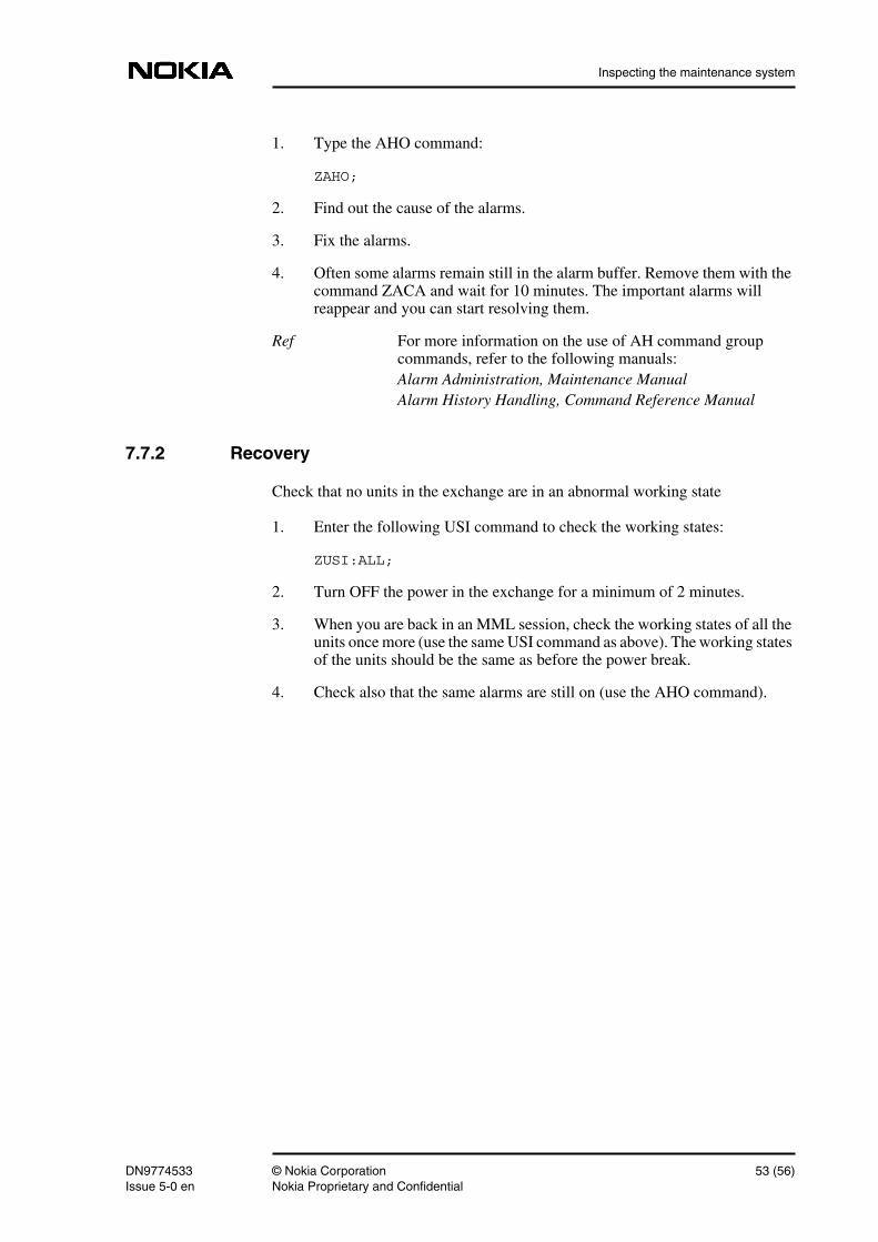
7.7.1 Alarms
Check which alarms are currently on in the exchange
52 (56) © Nokia Corporation DN9774533Nokia Proprietary and Confidential Issue 5-0en
Inspecting the maintenance system
1. Type the AHO command:
ZAHO;
2. Find out the cause of the alarms.
3. Fix the alarms.
4. Often some alarms remain still in the alarm buffer. Remove them with thecommand ZACA and wait for 10 minutes. The important alarms willreappear and you can start resolving them.
Ref For more information on the use of AH command groupcommands, refer to the following manuals:Alarm Administration, Maintenance ManualAlarm History Handling, Command Reference Manual
7.7.2 Recovery
Check that no units in the exchange are in an abnormal working state
1. Enter the following USI command to check the working states:
ZUSI:ALL;
2. Turn OFF the power in the exchange for a minimum of 2 minutes.
3. When you are back in an MML session, check the working states of all theunits once more (use the same USI command as above). The working statesof the units should be the same as before the power break.
4. Check also that the same alarms are still on (use the AHO command).
DN9774533 © Nokia Corporation 53 (56)Issue 5-0 en Nokia Proprietary and Confidential

Commissioning DX 200 Based Network Elements
54 (56) © Nokia Corporation DN9774533Nokia Proprietary and Confidential Issue 5-0en
O&M connections
8 O&M connectionsThe integration of the exchange can be carried out via the OMC (operation andmaintenance centre) and if this is to be done, the O&M connection should be setup. For more information on how to set up the O&M connection, refer to thefollowing manuals:
• Operation and Maintenance Connections, Operating Manual
• Integration Manual
DN9774533 © Nokia Corporation 55 (56)Issue 5-0 en Nokia Proprietary and Confidential

Commissioning DX 200 Based Network Elements
56 (56) © Nokia Corporation DN9774533Nokia Proprietary and Confidential Issue 5-0en