dvs ef fireplace owner's manual - lopi · pdf filedvs ef fireplace owner's manual...
TRANSCRIPT
AAAAAAAAAAAAAAAAAAAAAAAAAAAAAAAAAAAAAAAAAAAAAAAAAAAAAAAAAAAAAAA
DVS EF Fireplace Owner's Manual
Featuring the
Burner
Tested and Listed by
OMNI-Test Laboratories, Inc.Beaverton, Oregon
Report # 028-S-16B-5ANSI Z21.88
• Built-In Direct Vent Fireplace
• Natural Gas or Propane
• Residential or Mobile Home
WARNING: If the information in these instructions is not followed exactly, a fire orexplosion may result causing property damage, personal injury or loss of life.
- Do not store or use gasoline or other flammable vapors and liquids in the vicinity of this or anyother appliance.
WHAT TO DO IF YOU SMELL GAS• Do not try to light any appliance.• Do not touch any electrical switch; do not use any phone in your building.• Immediately call gas supplier from a neighbor's phone. Follow the gas supplier's instructions.• If you cannot reach your gas supplier, call the fire department.
- Installat ion and service must be performed by a qualified installer, service agency or the gassupplier.
This appliance may be installed as an OEM installation in a manufactured (mobile) home andmust be installed in accordance with the manufacturer’s instructions and the manufactured homeconstruction and safety standard, Title 24 CFR, Part 3280.
This appliance is only for use with the type(s) of gas indicated on the rating plate. Aconversion kit is supplied with the appliance.
Installer: After installation give this manual to the home-ownerand explain operation of this heater.
Copyright 2007, Travis Industries, Inc. $10.00 100-01152
Travis Industries, Inc.4800 Harbour Pointe Blvd. SW
Mukilteo, WA 98275

2 Introduction
Travis Industries 4031009 100-01152
Introduction
We welcome you as a new owner of a Travis Industries gas fireplace. In purchasing this fireplace you have joinedthe growing ranks of concerned individuals whose selection of an energy system reflects both a concern for theenvironment and aesthetics. The Travis Industries DVS EF Fireplace is one of the finest home heaters the worldover. This manual will explain the installation, operation, and maintenance of this fireplace. Please familiarizeyourself with the Owner's Manual before operating your heater and save the manual for future reference. Includedare helpful hints and suggestions that will make the operation and maintenance of your new fireplace an easier andmore enjoyable experience. We offer our continual support and guidance to help you achieve the maximumbenefit and enjoyment from your heater.
Important InformationNo other DVS EF gas fireplace has the same serialnumber as yours. The serial number is below and tothe left of the gas control valve.
This serial number will be needed in case you requireservice of any type.
Model: DVS EF Fireplace
Serial Number:
Purchase Date:
Purchased From:
Mail your Warranty CardToday, and Save Your Bill ofSa le .
To receive full warranty coverage,you will need to show evidence ofthe date you purchased yourheater. Do not mail your Bill ofSale to us.
We suggest that you attach yourBill of Sale to this page so that youwill have all the information youneed in one place should the needfor service or information occur.
Table of Contents 3
© Travis Industries 4041213 100-01152
IntroductionIntroduction & Important Information................2
Safety PrecautionsSafety Precautions ......................................4
Features & SpecificationsFeatures ....................................................6Installation Options......................................6Heating Specifications..................................6Dimensions.................................................6
InstallationInstallation Warning......................................7Packing List................................................7Additional Items Required for Installation..........7Installation Overview....................................7Fireplace Placement Requirements..................8
Minimum Framing Dimensions ....................8Clearances ............................................8Corner Installations .................................9Raised Fireplaces....................................9
Hearth Requirements....................................10Facing Requirements....................................11Facing Over 1" Thick.....................................11Facing Detail ...............................................12Face Dimensions .........................................13Modifying the Face Angle...............................14Facing & Hearth Examples.............................15Mantel Requirements....................................16Vent Requirements.......................................17
Altitude Considerations ............................17Clearances ............................................17Use of 8” Dia. Pipe...................................17Vent Installation......................................17
Approved Vent Configurations........................18Restrictor Position...................................18Measuring Vent Lengths...........................18Vertical Terminations (with/ without offsets)..19Horizontal Terminations............................20Vertical Terminations (with 2 90° Elbows)......21
Vent Termination Requirements ......................22Gas Line Requirements.................................23
Fuel ......................................................23Gas Line Connection................................23Gas Inlet Pressure ..................................23
Electrical Connection....................................24
Finalizing the Installation1 Glass Removal (& installation)......................252 Log & Coal Installation................................263 Purge Gas Line and Replace the Glass ..........274 Faceplate Installation.................................275 Leak Test.................................................276 Pilot Adjustment (if necessary).....................277 Air Shutter Adjustment (if necessary) ............278 Check Flame.............................................289 Explain Operation to Home-Owner.................28
OperationBefore You Begin.........................................29Location of Controls .....................................29Starting The Pilot .........................................30Starting the Fireplace for the First Time.............31Turning the Fireplace On and Off .....................31Adjusting the Flame Height.............................31Adjusting the Blower Speed............................32Normal Operating Sounds..............................32Normal Operating Odors................................32
MaintenanceYearly Service Procedure..............................33Troubleshooting Table...................................34How this Fireplace Works...............................35
What Turns the Main Burners On and Off......35What Prevents Gas Buildup.......................35
Wiring Diagram ............................................36Replacement Parts List .................................36
Safety LabelSafety (Listing) Label....................................37
WarrantyWarranty ....................................................38
Optional EquipmentLP Conversion Kit ........................................39
Index Index.........................................................42

4 Safety Precautions
© Travis Industries 4041213 100-01152
IF YOU SMELL GAS:Do not light any appliance
Extinguish any open flame
Do not touch any electrical switch or plug or unplug anything
Open windows and vacate building
Call gas supplier from neighbor's house, if not reached, call fire department
This unit must be installed by a qualified installer to prevent the possibility of an explosion.Your dealer will know the requirements in your area and can inform you of those peopleconsidered qualified. The room heater should be inspected and cleaned before use andat least annually by a qualified service person. More frequent cleaning may be requireddue to excessive lint from carpeting, bedding material, etc.
The instructions in this manual must be strictly adhered to. Do not use makeshift methodsor compromise in the installation. Improper installation will void the warranty and safetylisting.
For LPG only | Pout 11” W.C.
Look for this label:
If the label is present, the heater is equipped for LP (propane). If the label is absent, the heater is equipped for NG (natural gas).
This heater is either approved for natural gas(NG) or for propane (LP). Burning theincorrect fuel will void the warranty and safetylisting and may cause an extreme safetyhazard. Direct questions about the type offuel used to your dealer. Check the label andflame adjust knob on the gas control valve.
Ok
Contact your local buildingofficials to obtain a permit andinformation on any installationrestrictions or inspectionrequirements in your area.Notify your insurance companyof this heater as well.
If the flame becomes sooty, darkorange in color, or extremely tall,do not operate the heater. Callyour dealer and arrange forproper servicing.
It is imperative that controlcompartments, screens, orcirculating air passageways ofthe heater be kept clean andfree of obstructions. Theseareas provide the air necessaryfor safe operation. ?
Do not operate the heater if it isnot operating properly in anyfashion or if you are uncertain.Call your dealer for a fullexplanation of your heater andwhat to expect.
Gas
Do not store or use gasoline orother flammable liquids in thevicinity of this heater.
AAAAAAAAAAAAAAA
AAAAAAAAAAAAAAAAAAA
Do not operate if any portion of theheater was submerged in water or ifany corrosion occurs. Immediatelycall a qualified service technician toinspect the appliance and to replaceany part of the control system andany gas control wash has beenunder water.

Safety Precautions 5
© Travis Industries 4041213 100-01152
Do not place clothing or otherflammable items on or near theheater. Because this heater canbe controlled by a thermostatthere is a possibility of the heaterturning on and igniting any itemsplaced on or near it.
AAAAAAAAA
Light the heater using the built-in piezo igniter. Do not usematches or any other externaldevice to light your heater.
Never remove, replace, modifyor substitute any part of theheater unless instructions aregiven in this
The viewing glass should beopened only for lighting thepilot or conducting service. Donot operate with cracked,broken, or removed glass.
Any safety screen or guardremoved for servicing must bereplaced prior to operating theheater.
manual. All other work must bedone by a trained technician.Don't modify or replace orifices.
Allow the heater to cool beforecarrying out any maintenance orcleaning.
Operate the heater according tothe instructions included in thismanual.
If the main burners do not startcorrectly turn the gas off at thegas control valve and call yourdealer for service.
The pilot flame must contact thethermopile and thermocouple(see the illustration to the left). Ifit does not, turn the gas controlvalve to "OFF" and call yourdealer.
AAAAAAAA
This unit is not for use with solidfuel
Do not place anything inside thefirebox (except the includedfiber logs).
If the fiber logs becomedamaged, replace with TravisIndustries log set.
ThisManual
Do not throw this manual away.This manual has importantoperating and maintenanceinstructions that you will need ata later time. Always follow theinstructions in this manual.
Children and adults should bealerted to the hazards of highsurface temperature and shouldstay away to avoid burns orclothing ignition. Young childrenshould be supervised whenthey are in the same room as theheater.
Travis Industries, Inc.grants no warranty, impliedor stated, for theinstallation or maintenanceof your heater, andassumes no responsibilityof any consequentialdamage(s).
Instruct everyone in the househow to shut gas off to theappliance and at the gas mainshutoff valve. The gas mainshutoff valve is usually next tothe gas meter or propane tankand requires a wrench to shutoff.

6 Features and Specifications
© Travis Industries 4041213 100-01152
Features:- Works During Power Outages (millivolt system)- High Efficiency- Optional Thermostat or Remote Control- Realistic "Wood Fire" Look- Quiet Blower for Effective Heat Distribution- Convenient Operating Controls- Variable-Rate Heat Output- Low Maintenance
Installation Options:- Residential or Mobile Home- Straight or Corner Placement- Flush or Recessed Face- Raised or Floor Hearth- Internal or External Chase- Horizontal or Vertical Vent- Bedroom Approved
Heating Specifications: Natural Gas PropaneApproximate Heating Capacity (in square feet)* 500 to 1,500 500 to 1,500BTU Input Per Hour (from high to low) 31,000 – 18,600 31,000 - 16,000Steady State Efficiency** (with blowers on) Up to 80% Up to 80.5%AFUE (Annual Fuel Utilization Efficiency) 71.3% 71.8%* Heating capacity will vary with floor plan, insulation, and outside temperature.
** Efficiency rating is a product thermal efficiency rating determined under continuous operationindependent of installed system.
Vent has an external diameter of 6-5/8"
Weight: 165 Lbs.
Dimensions: Electrical access panel is 6" behind the front, along the base.
1/2" Stand-offs
* Includes the 1/2" clearance
Nail Down Plate (used to secure the fireplace to the floor)
See "Gas Line Connection" on page 22 for more details
2"
37"*
28-1/8"*
28-1/2"
14-1/2"
29-1/8"
20-3/8"
1-1/2"
1"
34-3/4"
2-5/8"
7-3/4"
19-3/8"*
2"
4-7/8"

Installation (for qualified installers only) 7
© Travis Industries 4041213 100-01152
Installation Warnings:• Failure to follow all of the requirements may result in property damage, bodily
injury, or even death.• This heater must be installed by a qualified installer who has gone through a
training program for the installation of direct vent gas appliances.• This appliance must be installed in accordance with all local codes, if any; if not,
follow ANSI Z223.1 and NFPA 54(88).• In Manufactured or Mobile Homes must conform with Manufactured Home
Construction and Safety Standard, Title 24 CFR, Part 3280, or, when such astandard is not applicable, the Standard for Manufactured Home Installations,ANSI/NCSBCS A225.1. This appliance may be installed in Manufactured Housingonly after the home is site located.
• The fireplace is designed to operate on natural gas, or propane (LP).• All exhaust gases must be vented outside the structure of the living-area.
Combustion air is drawn from outside the living-area structure.• Notify your insurance company before hooking up this fireplace.• The requirements listed below are divided into sections. All requirements must be
met simultaneously. The order of installation is not rigid – the qualified installershould follow the procedure best suited for the installation.
Packing List• Propane Conversion Kit• Log Set (3 Logs, 2 Twigs, Bag of Coals, Coal Trays)• Restrictor Adjuster Rod• Flex Tube with Pipe Adapter
Additional Items Required• Faceplate• Direct Vent (Simpson Dura-Vent Ph. # 800 835-4429)• Gas Line Equipment (shutoff valve, pipe, etc.)• Electrical Equipment
Installation Overview
AAAAAAAAAAAAAAAA
AAAAAAAAAAAAAAAAAAAAAAAAAAA
AAAAAAAAAAAAAAAAAAAAAAAA
AAAAAAAAAAAAAAAAAAAAAAAA
AAAAAAAAAAAAAAAA
Non-combustible facing (see "Facing Requirements")
See "Horizontal Termination Requirements"
See "Electrical Connection"
See "Mantel Requirements"
Insulation must not fill the spaces between the stand-offs
See "Fireplace Placement Requirements"
The faceplate must be 6" minimum from side walls.
See "Vent Requirements"
See "Minimum Framing Dimensions"
See "Hearth Requirements"
Drywall
Nail Down Plate
See "Gas Line Installation"
See "Acceptable Vent Lengths"
Optional thermostat or remote control wire.

8 Installation (for qualified installers only)
© Travis Industries 4041213 100-01152
Fireplace Placement Requirements
Setting Up the Standoffs
Standoff
a
Replace the screw to secure the standoff.
Bend the standofff in the sequence shown.
1/4"
Nut
driv
er
Remove the screw below the standoff.
b
1
2
3
c
The standoffs are shipped in the flat position. Make sure to follow the instructions below before installing the fireplace.
AFTER
BEFORE
WARNING : Failure to set up the standoffs will result in an extreme fire hazard.
Minimum Framing Dimensions
- A 1/2" clearance is required alongthe sides and back of the fireplace.The 1/2" stand-offs on the sidesand 6-1/4" stand-offs on the top ofthe fireplace are designed toseparate the fireplace from theframing members. These stand-offs may contact the framingmembers but no material may beplaced between the stand-offs.
- Fireplace must be installed on alevel surface capable ofsupporting the fireplace and vent
- Fireplace must be placed directlyon wood or non-combustiblesurface (not on linoleum orcarpet)
- This heater may be placed in abedroom. Please be aware ofthe large amount of heat thisappliance produces whendetermining a location.
Gas Line (the inlet is 7-3/4" behind the framing and 2-5/8" above the base of the fireplace (see "Gas Line Connection" for details).
37-1/4"
19-5/8"
35"
Route the electrical line (and optional thermostat or remote control wire) to the right of the fireplace.
NOTE: when venting to the rear, allow a min. 8-5/8" gap centered behind the fireplace (for the vent and wall thimble).
36" From Base of Fireplace.
NOTE: when using an elbow off the top of the fireplace, allow for a 2" clearance above the vent (1" to the sides and bottom).
Clearances
• When installed, walls in front of the fireplace must be a minimum 6" to the side of the faceplate.
• Due to the high temperature of the fireplace, it should be located out of traffic and away from furnitureand draperies.
• Fireplace must be placed so the vents below and above the glass do not become blocked

Installation (for qualified installers only) 9
© Travis Industries 4041213 100-01152
Corner Installations
A typical 45° installation uses theminimum framing dimensions shownin the illustration to the right (Normalclearances still apply).
AAAAAAAAA
AAAAAA
AAAAAAAAAAAAAAAAAAAAA
46-3/4"19-3/8"
Fireplace (includes
1/2" standoffs)
13"
14-3/8"
65-3/4"
37"
13-5/8"
Raised Fireplaces
• The fireplace (and hearth, if desired) may be placed on a platform designed to support the fireplace(250 Lbs.) and vent.
• The fireplace may be raised a maximum 34" (this is to ensure the mantel clearance does not infringeupon the ceiling).
Raised fireplaceRaised fireplace with raised hearth.
Raised Platform
Nail the nail down plates to the floor (or raised platform)
Raised Hearth
Hearth
Raised Platform

10 Installation (for qualified installers only)
© Travis Industries 4041213 100-01152
Hearth Requirements
AAAAAAAAAAAAAAAAAAAAAAAAAAAAAAAAAAAAAAAAAAAAAAAAAAAAAAAAAAAAAAAAAAAAAAAAAAAAAAAAAAAAAAAAAAAAAAAAAAAAAAAAA
AAAAAAAAAAAAAAAAAAAAAAAAAAAAAAAAAAAAAAAAAAAAAAAAAAAAAAAAAAAAAAAAAAAAAAAAAAAAAAAAAAAAAAAAAAAAAAAAAAAAAAAAAAAAAAAAAAAAAAAAAAAAAAAAAAAAAAA
AAAAAAAAAAAAAAAAAAAAAAAAAAAAAAAAAAAAAAAAAAAAAAAAAAAAAAAAAAAAAAAAAAAAAAAAAAAAAAAAAAAAAAAAAA
AAAAAAAAAAAAAAAAAAAAAAAAAAAAAAAAAAAAAAAAAAAAAAAAAAAAAAAAAAAAAAAAAAAAAAAAAAAAAAAAAAAAAAAAAAAAAAAAAAAAAAAAAAAAAAAAAAAAAAAAAAAAAAAAAAAAAAA
Do not build the hearth above this ledge.
12” Min.
2 Pieces of 1/2” Cement Board
Tile, Marble, Brick, or other Non-Combustible
Decorative Trim (may be combustible)
Min. 1-1/4”Max. 1-7/16”
Floor Mounted Fireplaces
Raised Fireplaces
AAA
AAAAAAAAAAAAAAAAAAAAAAAAAAAAAAAAAAAAAAAAAAAAAAAAAAAAAAAAAAAAAAAAAAAAAAAAAAAAAAAA
AAAAAAAAAAAAAAAAAAAAAAAAAAAAAAAAAAAAAAAAAAAAAAAAAAAAAAAAAAAAAAAAAAAAAA
AAAAAAAAAAAAAAAAAAAAAAAAAAAAAAAAAAAAAAAAAAAAAAAAAAAAAAAAAAAAAAAAAAAAAAAAAAAAAAAAAAAAAAAAAAAAAAAAAAAAAAAAAAAAAAAAAAAAAAAAAAAAAAAAAAAAAAAAAAAAAAAAAAAAAA
AAAAAAAAAAAAAAAAAAAAAAAA
AAAAAAAAAAAAAAAAAAAAAAAAAAAAAAAAAAAA
Fireplace Stand
Tile, Marble, Brick, or other Non-Combustible
Non-Combustible
Hearth (Min. 1-1/4”)
AAAAAAAAAAAAAAAAAAAAAAAAAAA
AAAAAAAAAAAAAAAAAAAAAAAAAAAAAAAAAAAAAAAAAAAAA
AAAAAAAAAAAAAAAAAAAAAAAAAAA
AAAAAAAAAAAAAAAAAAAAAAAAAAAAAAAAAAAAAAAAAAAAA
AAAAAAAAAAAAAAAAAAAAAAAAA
AAA
AAAAAAAAAAAAAAAAAAAAAAAAAAAAAAAAAAAAAAAAAAAAAAAAAAAAAAA
AAAAAAAAAAAAAAAAAAAAAAAAAAAAAAAAAAAAAAAAAAAAAAAAAAAAAAA
AAAAAAAAAAAAAAAAAAAAAAAAAAAAAAAAAAAAAAAAAAAAAAAAAAAAAAAAAAAAAAAAAAAAAAAAAAAAA
12” Min.
2 Pieces of 1/2” Cement Board
Min. Hearth Width:The hearth must extend the width of the face - see “Face Dimensions” for sizing.
AAAAAAAAAAAAAAAAAAAA
AAAAAAAAAAAAAAAAAAAA
AAAAAAAAAAAAAAAAAAAA
Non-Combustible
Hearth (Min. 1-1/4”)
Raised Hearth
Floor Hearth
Min. Hearth Width:The hearth must extend the width of the face - see “Face Dimensions” for sizing.

Installation (for qualified installers only) 11
© Travis Industries 4041213 100-01152
Facing RequirementsNOTE: The combustible area above the facing must not protrude more than 3/4" from the facing. If it
does, it is considered a mantel and must meet the mantel requirements listed in this manual.
Adhesive
WARNING : Do not use adhesive to secure the cement board or facing. The hightemperatures of the fireplace may cause adhesives to emit odors. Use mastic or thin set (orother non-combustible, non-odorous adherent) to attach the facing to the cement board.NOTE: Screws may be used to secure the cement board to the fireplace. Do not penetratethe fireplace more than 3/4”
AAAAAAAAAAAAAAAAAAAAAAAAAAAAAA
6" Min.(both sides)
Non-combustible Facing
AAAAAAAAAAAAAAAAAAAAAAAAAAAAAAAAAAAAAAAAAAAAAAAAAAAAAAAAAAAAAAAAAAAAAAAAAAAAAAAAAAAAAAAAAAAAAAAAAAAAAAAAAAAAAAAAAAAAAAAAAAAAAAAAAAAA
The fireplace requires a concrete board (or other
non-combustible) extending from the header to
the floor and to the framing members on both
sides. Do not use sheetrock, plywood or other
combustible material.
Arch Face
Rectangular Face
12" Min.
Header
Bottom of
Faceplate
NO DRYWALL
1-1/2"
Base of
Fireplace
See “Face Dimensions”
for face sizing.
Facing Over 1" Thick
WARNING :Faces that attach with latch-hooks(Avalon Rosario, Avalon Cambridge,Avalon Salish Bay, Avalon Rawhide,Lopi Discovery, Lopi Heritage Bay, FPXArchitectural Faces (all styles),require a 5/8” gap above thef a c e for face installation and removal.
• If the facing material is over 1" thick(e.g. brick, river rock), install the facingaround the perimeter of the face. Youmay wish to make a facing support (seethe illustration to the right). If using anarch face, you may wish to order theoptional set-up face:
Arch Set-Up Face is available fromTravis Industries (Part # 98500697)
• Artisan faces vary in size. Use the facebeing installed to create a template.
AAAAAAAAAAAAAAAAAAAAAAAAAAAAAAAAAAAAAAAAAAAAAAAAAAAAAAAAAAAAAAAAAAAAAAAAAAAAAAAAAAAAAAAAAAAAAAAA
AAAA
AAAAAAAAAAAAAAAAAAAAAAAAAAAAAAAAAAAAAAAAAAAAAAAAAAAAAAAAAAAAAAAAAAAAAAAAAAAAAAAAAAAAAAAAAAAAAAAAAAAAAAAA
AAAAAAAAAAAAAAAAAAAAAAAAAAAAAAAAAAAAAAAAAAAAAAAAAAAAAAAAAAAAAAAAAAAAAAAAAAAAAAAAAAAAAAAAAAAAAAAAAAAAAAAA
AAAAAAAAAAAAAAAAAAAAAAAAAAAAAAAAAAAAAAAAAAAAAAAAAAAAAAAAAAAAAAAAAAAAAAAAAAAAAAAAAAAAAAAAAAAAAAAAAAAAAAAAAAAAAAAAAAAAAAAAAAAAAAAAAAAAAAAAAAAAAAAAAAAAAAAAAAAAAAAAAAAAAAAAAAAAAAAAAAAAAAAAAAAAAAAAAAAAAA
AAAA
AAAAAAAAAAAAAAAAAA
AAAAAAAAAAAAAAAAAAAAAAAAAAAA
AAAAAAAAAAAAAAAAAAAAAAAAAAAA
AAAAAAAAAAAAAAAAAAAAAAAAAAAA
Make a facing support using
2x4’s. It should be 1/8” larger
than the finished face. NOTE:
The bottom of the face is 1-1/2”
above the base of the fireplace.1-1/2”
Note: if using a brick hearth, the fireplace will need to be raised to accommodate the 1-1/2” gap betwen the
face and the base of the fireplace. For 2-1/2” thick brick this works out to approximately 1-1/8”.
AAAAAAAAAAAAAAAAAAAAAAAAAAAAAAAAAAAAAAAAAAAAAAAAAAAAAAAAAAAAAAAAAAAAAAAAAAAAAAAAAAAAAAAAAAAAAAAAAAAAAAAA
AAAAAAAAAAAAAAAAAAAAAAAAAAAAAAAAAAAAAAAAAAAAAAAAAAAAAAAAAAAAAAAAAAAAAAAAAAAAAAAAAAAAAAAAAAAAAAAAAAAAAAAAAAAAAAAAAAAAAAAA
AAAAAAAAA
The brick facing must meet the same requirements
listed in “Facing Requirements”.
AAAAAAAAAAAAAAAAAAAAAAAA
Center Line
AAAAAAAAAAAAAAAAAA
Rectangular Faces
Use the optional Arch
Set-Up Face available
from Travis
Industries.
Arch Faces
Face Sizing:
See “Face
Dimensions” for
sizing.

12 Installation (for qualified installers only)
© Travis Industries 4041213 100-01152
Facing Detail
Access Door
AAAAAAAAAAAAAAAAAAAAAAAAAAAAAAAAAAAAAAAAAAAAA
1-1/2"
Face1"
1-7/16” Lopi Discovery 1-7/16” Avanti DVS7/16” FPX Rect. and Arched
Glass
1/8"
Air Space
The overlap is 1-1/2" along the top of the face.
NOTE:
Do not tuck tile underneath the face on the bottom (there will be a 1/8" air space below the access door). You may do this on the sides and top, but not on the bottom.
AAAA
AA
29-1/8”
20-3/8”
1"1-1/2"
Make sure these shaded areas are faced over when using the arched face. Rectangular faces do not require this area to be faced.2” 4-7/8”
• To achieve a facing that is flush with the drywall to the side of the fireplace, recess the framing directlynext to the fireplace. See the illustration below.
Fireplace
1"
1/2" Drywall
AAAAAAA1/2" Concrete Board3/8" Tile
This 2x4 is recessed 3/8" to make a flush facing
Fireplace1/2" Drywall
AAAAAAA
1/2" Concrete Board
3/8" TileThe tile overlaps the drywall for an overlap facingFaceplate
1"
TOP VIEW
Faceplate

Installation (for qualified installers only) 13
© Travis Industries 4041213 100-01152
Lopi Discovery DVS
21-9/16”
32”
Avalon Rosario DVS
21-9/16”32”
FPX Rectangular DVS
30”
22”
Lopi Heritage Bay DVS
31-5/8”
21-1/2”
5-7/8”
Avalon Salish Bay DVS
5-3/8”
22-1/2”
30-1/2”
22”
3-1/2"
30”
Radius = 34”
FPX ArchedFPX ArtisanNOTE: artisan faces vary in size.
2”
Avalon Cambridge DVS
33-7/8”
33”
FPX Architectural Faces
29-7/8”
22-3/4”
21-1/2”
32”
21-1/2”
2-3/8”
2-1/2”
23-5/8”
11-1/8”
Avalon Craftsman Face
Lopi Bedford Face
34-1/8”
22-3/4”(+ 5/8” for
installation)
33-1/8”
2-1/4”
Face Dimensions
AAAAAAAAAAAAAAAAAAAAAAAAAAAAAAAAAAAAAAAAAAAAAAAAAAAAAAAAAAAAAAAAAAAAAAAAAAAAAAAAAAAAAAAAAA
AAAAAAAAAAAAAAAAAAAAAAAAAAAAAAAAAAAAAAAAAAAAAAAAAAAAAAAA
32”
22-1/2”
Avalon Victorian
Avalon Rawhide
22 1/2”
32”
Modifying the Face Angle for Rectangular Faces
• If using a rectangular face (faces other than the Craftsman or FPX Arched), adjust the face angles atthe top corners of the glass (see the illustration below).
AAAAAAAAAAAAAA
AAAAAA
Remove these four screws from the face angle.
Phillips Screwdriver
Bend the face angle up and replace the two screws on the upper section.
AAAAAAAAAAAAAA
AAAAAA
AAAAAAAAAAAAAA
AAAAAAAAAAAA
Re-bend the face angle at the inward location and re-attach the lower portion with one screw.
AAAAAAAAAAAAAA
AAAAAAAAAAAA
Straighten the face angle.ba dc
Front of Fireplace
Glass

14 Installation (for qualified installers only)
© Travis Industries 4041213 100-01152
Facing and Hearth Examples
AAAAAAAAAA
AAAAAAAAAAAAAAAAAAAAAA
AAAAAAAAAAAAAAAAAAAAAAAAAAAAAAAAAAAAAAAAA
DVS Fireplace
Face
3/8" Thick TileTwo 1/2"
Cement Boards
Wood Sub Floor
1-1/2"
Side View
AAAAAAAAAA
2x4 and Plywood Platform
Side of Fireplace
AAAAAAAAAAAAAAAAAAAAAAAAAAAA
AAAAAAAAAAAAAAAAAAAAAAAAAAAAAA
AAAAAAAAAAAAAAAAAAAAAAAAAAAAAAAAAAAAAAAAAA
Note how the tile facing fits behind the face on the side and top and butts up to the set-up face on the bottom.
When fully installed, there will be a 1/8" air space below the access door on the face. Do not block this space (it is required for access door opening and air flow).
Three-Dimensional View
Tile
Cement Board
2x4 and Plywood Platform
SUGGESTION:
Base of Fireplace
Base of Fireplace
1/2" Cement Board & 3/8" Tile (tucked behind the face)
NOTE:
AAAAAAA
Face
Make your platform height a dimension that will accommodate the size tiles you are using and the 1-1/2" between the base of the fireplace and the bottom of the face.
Installation (for qualified installers only) 15
© Travis Industries 4041213 100-01152
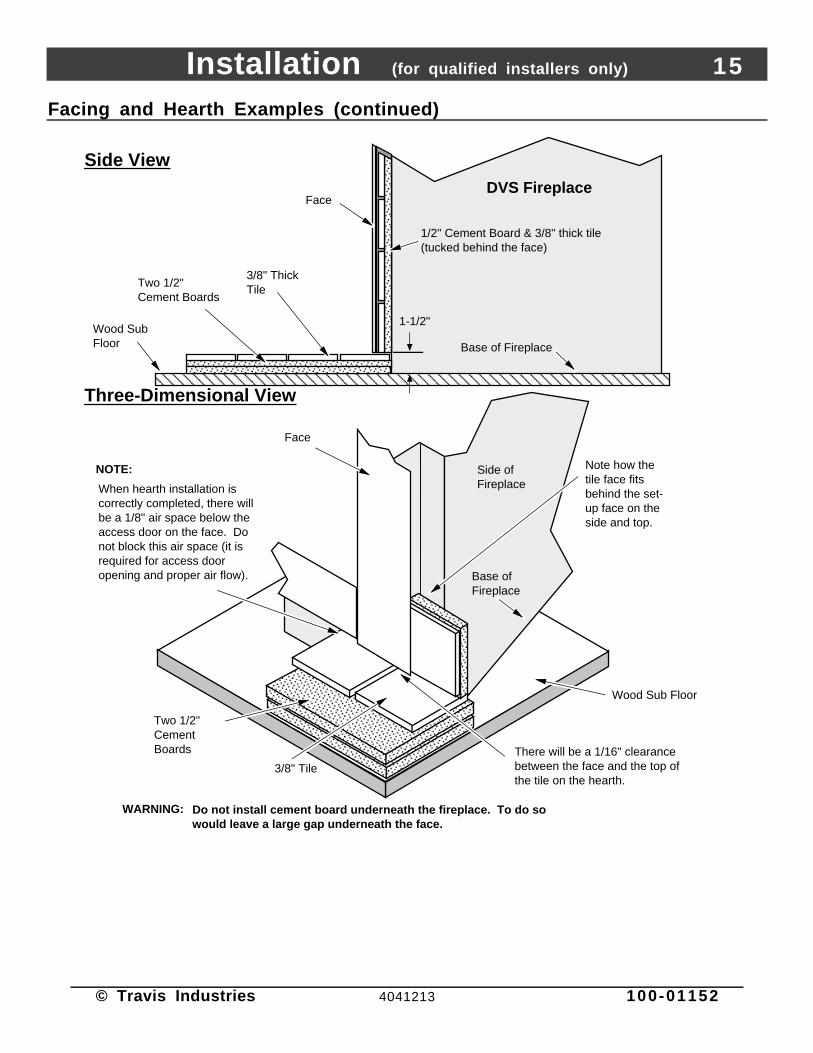
Facing and Hearth Examples (continued)
AAAAAAAAAAAAAAAAAAAAAAAAAA
DVS FireplaceFace
3/8" Thick Tile
Two 1/2" Cement Boards
Wood Sub Floor
1-1/2"
AAAAAAAA
1/2" Cement Board & 3/8" thick tile(tucked behind the face)
Side View
Three-Dimensional View
Side of Fireplace
Note how the tile face fits behind the set-up face on the side and top.
When hearth installation is correctly completed, there will be a 1/8" air space below the access door on the face. Do not block this air space (it is required for access door opening and proper air flow).
3/8" Tile
Two 1/2" Cement Boards
WARNING:AAAAAAAAAAAAAAAAAAAAAAAAAAAAAAAA
AAAAAAAAAAAAAAAAAAAAAAAAAAAAAAAAAAAAAAAA
AAAAAAAAAAAAAAAAAAAAAAAA
AAAAAAAAAAAAAAAAAAAAAAAAAAAAAAAAAAAAAAAA
AAAAAAAAAAAA
AAAAAAAA
Base of Fireplace
Base of Fireplace
There will be a 1/16" clearance between the face and the top of the tile on the hearth.
Wood Sub Floor
Do not install cement board underneath the fireplace. To do so would leave a large gap underneath the face.
NOTE:
AAAAAAAAAAAAAAAA
Face

16 Installation (for qualified installers only)
© Travis Industries 4041213 100-01152
Tile Hearths
AAAAAAAAAAAAAAAAAAAAAAAAAAAAAAAAAAAAAAAAAAAA
32 DVS FireplaceFace
3/8" Thick Tile, Marble, or Granite
Two Layers of 1/2" Cement Board
Wood Sub Floor
1-1/2"
Facing installs behind the face
Base of Fireplace
12" Min.
AAAAAAAA
Min. 1-3/8" Thick Hearth
The front and side edges can be trimmed in various ways:Min. 1-3/8" Thick Hearth
Bull-Nose TileAAAAAAAAAAAAAAAAAAAA
(Cut to 1-3/8")
AAAAAAAAAAAA
Edge Tile
(Cut to 1-3/8")
AAAAAAAAAAAAAAAAAAAAAA
Wood Molding
(Cut to 1-3/8")
Mantel Requirements
• The combustible area above the facing must not protrude more than 3/4" from the facing. If it does, itis considered a mantel and must meet the mantel requirements listed in this manual.
Combustible or Non-Combustible Mantels
Combustible or Non-Combustible Mantel
Max. Mantel Depth is 8”
Base of Fireplace
17” Minimum
1-1/2”
See “Face Dimensions” for face sizing.
Bottom of Faceplate

Installation (for qualified installers only) 17
© Travis Industries 4041213 100-01152
Vent Requirements
• Always maintain therequired 1" clearance (2"clearance above the ventwhen an elbow is placeddirectly off the top of thefireplace) to combustiblematerials to prevent a firehazard. Do not fill airspaces with insulation.
• The gas appliance and ventsystem must be venteddirectly to the outside ofthe building, and never beattached to a chimneyserving a separate solidfuel or gas-burningappliance. Each directvent gas appliance mustuse it's own separate ventsystem.
• In addition to therequirements below, followthe requirements providedwith the vent.
AltitudeConsiderations
Use a firestop spacer whenever passing through a ceiling (Duravent Part #963)
Vertical Termination (Duravent Part # 991)
Use a roof flashing and storm collar whenever passing through the roof(Duravent Part #953 & #943 or #943S)
8-5/8"(220 mm)
Use a support box on exposed vent
Vertical Vent Requirements
Use a firestop whenever passing through a wall
Horizontal Termination (Duravent Part #984)
Maintain a minimum 1" clearance from vent to any combustible (2" above the vent when an elbow is placed directly off the top of the fireplace).
Minimum Framing for wall thimble
Horizontal Vent Requirements
Minimum framing for fire stop
8-5/8"(220 mm)
Maintain a minimum 1" (25 mm) clearance from vent to any combustible (vent is 6 5/8" (170 mm) diameter)
6-5/8" Diameter
- This heater has been tested at altitudes ranging from sea level to 8,000 feet (2,400 M). In this testing we have found thatthe heater, with its standard orifice, burns correctly with just an air shutter adjustment.
- Failure to adjust the air shutter properly may lead to improper combustion which can create a safety hazard.Consult your dealer or installer if you suspect an improperly adjusted air shutter.
Approved Vent• Use of of the following 6-5/8" diameter co-axial gas direct vent systems:
Manuafacturer Series
Simpson Dura-Vent Model GS
Selkirk Hearth Products Direct-Temp
American Metal Products Ameri-Vent
N O T E : Always use the high-wind cap for the type of vent you are using (if applicable)
• Slide the vent sections together and turn 1/4 turn until the sections lock in place.
• Screws are not required to secure the vent. However, three screws may be used to securevent sections together if desired.
• High temperature sealant is recommended at the appliance starter section connection (usehigh-temperature silicone or Mill-Pac®).
• If disassembly is required, at time of re-assembly check to see if the vent creates a tight fit. Ifit does not, apply high temperature sealant to the joints of the affected sections.
• Horizontal sections require a 1/4" rise every 12" of travel
• Horizontal sections require non-combustible support every three feet (e.g.: plumbing tape)

18 Installation (for qualified installers only)
© Travis Industries 4041213 100-01152
Approved Vent Configurations
Restrictor Position
A vent restrictor is built into the appliance to adjust the flow rate of exhaust gases. This ensures proper combustion forall vent configurations. Depending upon the vent configuration, you may be required to adjust the restrictor position.The charts for acceptable vent configurations describe which position the vent restrictor must be in.
To Adjust the Restrictor:
Withe the fireplace cool, use the bent rod included in the owner’s pack to adjust the plate.
To Access the Restrictor:
1
2
NOTE: The fireplace is shipped with the restrictor in position #1 (fully open).
Determine the correct restrictor position (see the charts under "Approved Vent Configurations" - the stock position is #1).Lift up the adjustment plate and move it so the correct notch falls into the slot on the adjustment bracket.
This restrictor is in position 1.This restrictor is in position 2.
AAAAAAAAAAAAAAAAAAAAAAAA
To adjust, use the rod included in the owner’s pack to lift up on the adjustment plate.
Adjustment Plate
Adjustment BracketPosition #3 is this notch.
MeasuringVentLengths
A maximum of two 90°elbows may be used.
NOTE: do not use a90° elbow betweentwo horizontalsections.
NOTE: oneadditional 45° elbowmay be used betweentwo horizontalsections.- or –Two 45° elbows maybe used betweenvertical sections.
Vent Horizontal
Run
Vent Height 30-1/2"
Vent Height is calculated to the top of the vent on horizontal terminations and to the top of the termination on vertical terminations.
Elbows add 3" to the length of the vent system.
Side View
9-5/8"
3"
1-1/2"
Vent Length(3', 4', etc.)
Vent sections overlap each other by 1-1/2"
1-1/2"
8-3/4" wide with 1-1/2" to 3-3/8" of overlap
12-3/8" tall with 1-1/2" of overlap

Installation (for qualified installers only) 19
© Travis Industries 4041213 100-01152
Vertical Terminations using 0 or 2 45° Offsets
•The termination must fall within theshaded area shown in the chart. Usethe indicated restrictor position.
Offset Length
Horizontal Offset
Vertical Rise
Offset Length Hor. Offset Vert. RiseNone 5" 1'1' Section 1' 1' 7"2' Section 1' 9" 2' 4"3' Section 2' 5" 3'4' Section 3' 2" 3' 8"
AAAAAAAAAAAAAAAAAAAAAAAAAAAAAAAAAAAAAAAAAAAAAAAAAAAAAAAAAAAAAAAAAAAAAAAAAAAAAAAAAAAAAAAAAAAAAAAAAAAAAAAAAAAAAAAAAAAAAAAAAAAAAAAAAAAAAAAAAAAAAAAA
5 feet
11' (min.)
15 feet
20 feet
25 feet
30 feet
0 feet
35' (max.)
0 fe
et
3 fe
et
6 fe
et
5 feet
0 feet
0 fe
et
The maximum offset length is three 4' sections.
Restrictor Position # 3
3 fe
et
6 fe
et
11' (min.)
15 feet
20 feet
25 feet
30 feet
35' (max.)
8' 7
"(m
ax.)
8' 7
"(m
ax.)
20 Installation (for qualified installers only)
© Travis Industries 4041213 100-01152
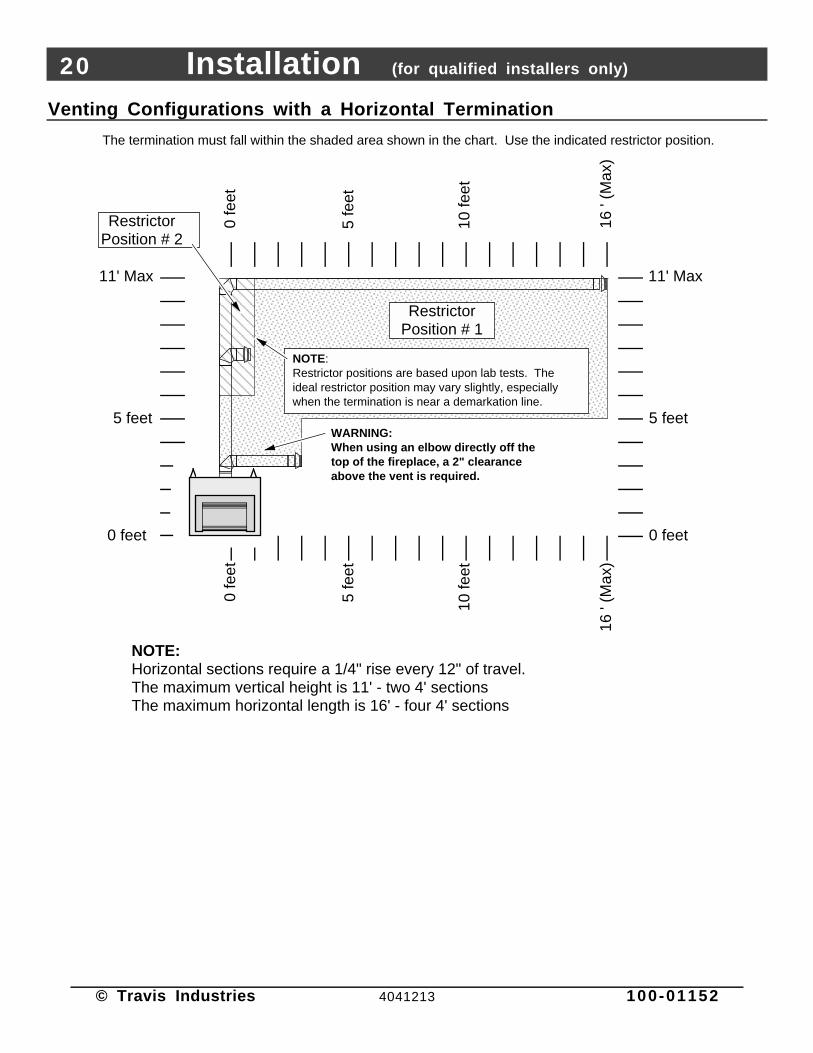
Venting Configurations with a Horizontal Termination
The termination must fall within the shaded area shown in the chart. Use the indicated restrictor position.
AAAAAAAAAAAAAAAAAAAAAAAAAAAAAAAAAAAAAAAAAAAAAAAAAAAAAAAAAAAAAAAAAAAAAAAAAAAAAAAAAAAAAAAAAAAAAAAAAA
AAAAAAAAAAAAAAAAAAAAAAAAAAAAAAAAAAAAAAAAAAAAAAAAAAAAAAAAAAAAAAAAAAAAAAAAAAAAAAAAAAAAAAAAAAAAAAAAAA
5 feet
0 feet
0 fe
et0
feet
NOTE: Horizontal sections require a 1/4" rise every 12" of travel.The maximum vertical height is 11' - two 4' sectionsThe maximum horizontal length is 16' - four 4' sections
16 '
(Max
)
Restrictor Position # 1
5 fe
et
11' Max
10 fe
et
16 '
(Max
)
5 fe
et
10 fe
et
5 feet
0 feet
11' Max
Restrictor Position # 2
NOTE:Restrictor positions are based upon lab tests. The ideal restrictor position may vary slightly, especially when the termination is near a demarkation line.
WARNING:When using an elbow directly off the top of the fireplace, a 2" clearance above the vent is required.

Installation (for qualified installers only) 21
© Travis Industries 4041213 100-01152
Vertical Terminations with 2 90° Elbows
The termination must fall within the shaded area shown in the chart. Use the indicated restrictor position.
AAAAAAAAAAAAAAAAAAAAAAAAAAAAAAAAAAAAAAAAAAAAAAAAAAAAAAAAAAAAAAAAAAAAAAAAAAAAAAAAAAAAAAAAAAAAAAAAAAAAAAAAAAAAAA
AAAAAAAAAAAAAAAAAAAAAAAAAAAAAAAAAAAAAAAAAAAAAAAAAAAAAAAAAAAAAAAAAAAAAAAAAAAAAAAAAAAAAAAAAAAAAAAAAAAAAAAAAAAAAAAAAAAAAAAAAAAAAAAAAAAAAAAAAAAAAAAAAAAAAAAAAAAAAAAAAAAAAAAAAAAAAAAAAAAAAAAAAAAAAAAAAAAAAAAAAAAAAAAAAAAAAAAAAAAAAAAAAAAAAAAAAAAAAAAAAAAAAAAAAAAAAAAAAAAAAAAAAAAAAAAAAAAAAAAAAAAAAA
NOTE: Horizontal sections require a 1/4" rise every 12" of travel.
Restrictor Position #3
NOTE:Restrictor positions are based upon lab tests. The ideal restrictor position may vary slightly, especially when the termination is near a demarkation line.
Restrictor Position # 2
NOTE: A min. 8' of vertical vent must be used.
0 feet
5 fe
et
10 fe
et
0 fe
et
0 feet
0 fe
et
16' (
max
)
5 feet
10' (min)
15 feet
20 feet
25 feet
30 feet
35 feet
5 feet
10' (min)
15 feet
20 feet
25 feet
30 feet
35 feet
5 fe
et
10 fe
et
16'(
max
)
37' (max)37' (max)

22 Installation (for qualified installers only)
© Travis Industries 4041213 100-01152
Termination Requirements (see the illustration below)
! Venting terminals shall not be recessed into a wall or siding.
A Minimum 9" clearance from any door or window
B Minimum 12" above any grade, veranda, porch, deck or balcony
C Minimum 3" from outside corner walls
D Minimum 12" from inside corner walls
E Minimum 11" clearance below unventilated soffits or roof surfacesMinimum 18" clearance below ventilated soffitsMinimum 6" clearance from roof eavesNOTE: Vinyl surfaces require 24"
11” Min.
6” Min.
Roof Surface
Roof Eaves
F Minimum 18" clearance below a veranda, porch, deck or balcony (must have two open sides)
G Minimum 48" clearance from any adjacent building
H Minimum 84" clearance above any grade when adjacent to public walkways or drivewaysNOTE: may not be used over a walkway or driveway shared by an adjacent building
I Minimum 48" clearance from any mechanical air supply inlet
J Minimum 36" clearance above and 48” below and to the sides of non-mechanical air supply inlet
K Minimum 36" from the area above the gas meter/regulator (vent outlet)
L Minimum 36" from the gas meter/regulator (vent outlet)
M Minimum 12” above the roof line (for vertical terminations)
N Minimum 24” horizontal clearance to any surface (such as an exterior wall) – for vertical terminations
C
B
H
E
G A
DF
L
K J
I
NOTE: Measure clearances to the nearest edge of the exhaust hood.
AE
E
M
N
• Use the vinyl siding standoff when installing on an exterior with vinyl siding.
• Vent termination must not be located where it will become plugged by snow or other material
• These clearances meet UMC-1994 code standards.

Installation (for qualified installers only) 23
© Travis Industries 4041213 100-01152
Gas Line Requirements
• The gas line must be installed in accordance with all local codes, if any; if not, follow ANSI 223.1 andthe requirements listed below.
• The fireplace and gas control valve must be disconnected from the gas supply piping during anypressure testing of that system at test pressures in excess of 1/2 psig. For pressures under 1/2 psig,isolate the gas supply piping by closing the manual shutoff valve.
• Leak test all gas line joints and the gas control valve prior to and after starting the fireplace.
Fuel
• This fireplace is designed either for natural gas or for propane (but not for both). Check the sticker onthe top of the gas control valve to make sure the correct fuel is used.
Gas Line Connection
• A manual shutoff valve is required within for installation (within 3’ of the heater). T-Handle gas cocksare required in Massachusetts in compliance with code 248CMR.
• Installation must be performed by a qualified installer, service agency or the gas supplier (InMassachusetts a licensed plumber/gasfitter).
10"
Gas Control Valve
3/8" M.P.T to 1/2" O.D. Fitting (Factory installed)
The 1" diameter access hole is located 2-7/8" above the base of the fireplace. Cut an "X" in the gasket covering the inlet and insert the gas line through the gasket.
10" Flex Tube (shipped with the fireplace - min. bending radius is 3/4")
5-1/2"
The included fitting accepts a 3/8" M.P.T. or
1/2" F.P.T.
-- OR --
-- OR --
7-3/4"
Gas Inlet Pressure: Standard Input Pressure
Natural Gas 7" W.C. (1.74 kPA)
Propane 13" W.C. (2.73 kPA)
• If the pressure is not sufficient, make sure the piping used is large enough, the supply regulator isadequately adjusted, and the total gas load for the residence does not exceed the amount supplied.
• The supply regulator (the regulator that attaches directly to the residence inlet or to the propane tank)should supply gas at the suggested input pressure listed above. Contact the local gas supplier if theregulator is at an improper pressure.

24 Installation (for qualified installers only)
© Travis Industries 4041213 100-01152
Electrical Connection
• Make sure the household breaker is shut off prior to working on any electrical lines.
• The fireplace must be properly grounded in accordance with local codes (or ANSI/NFPA 70-1987)
• The electrical line must be grounded and supply 120 Volts at 60 Hz (2 Amps)
• Follow the directions below to connect power to the fireplace.
Use wire nuts to connect the wires together. Push the connections inside the junction box, and re-attach the cover plate. Tighten the strain relief on to the outer insulation of the electrical line to insure the line does not pull loose.
Run an electrical line to a location at the right front of the fireplace
The junction box is located in the right rear corner of the fireplace. Remove the junction box cover plate to access the wires (use a standard screwdriver).
Feed the electrical line through the strain relief.
1 Remove the junction box cover at the right front corner of the fireplace near the base.
2 Feed the electrical line through the strain relief (use insulated Romex (®) type wire).
3 Remove the wires from the junction box. Expose approximately 1/2" of metal wire from each line ofthe electrical line. Use wire nuts to secure the wires together. Connect the green wire to the groundwire (usually green), the white wire to the common wire (usually white), and black wire to the hot wire(usually black).
N O T E : If using a thermostat or remote control , route the wire through the junction box alongwith the electrical line - see the section "Optional Equipment".
4 Push the wire connections into the junction box. Replace the cover plate.
5 Tighten the strain relief on to the outer insulation of the electrical line to secure.

Finalizing the Installation 25
© Travis Industries 4041213 100-01152
1 Remove the glass following the directions below.
Warning: The appliance must be completely cool before removing the glass.
Warning: Do not strike or slam the glass.
AAAA
Cross Section of Glass Attachment
AAAAAAAAAA
Glass
Glass Gasket (3/4" self-adhesive channel gasket)
Glass Clip
Glass Clip Attachment Studs
Face of Heater
Glass Clip Nuts
Loosen the nuts on the top and side glass clips until they are flush with the end of the stud (do not remove the nuts).
a
3/8"
Nut
driv
er
b
While holding the glass, loosen the nuts on the bottom glass clip until they are flush with the end of the stud. Pivot the glass forward and remove.
Tighten the nuts on the bottom glass clip first, then the top, then the sides.
Removing the Glass
AAAAAAAAAAAAAAAAAAAAAAAAAAAAAAAAAAAAAAAAAAAAAAAAAAAAAAAAAAAAAAAAAAAAAAAA
AAAAAAAAAAAAAAAAAAAAAAAAAAAAAAAAAAAAAAAAAAAAAAAAAAAAAAAAAAAAAAA
While holding the glass, slide the side and top glass clips off.
c
Replacing the Glass
AAAAAAAAAAAAAAAAAAAAAAAAAAAAAAAAAAAAAAAAAAAAAAAAAAAAAAAAAAAAAAAAAAAAAAAA
With the bottom glass clip in place and the nuts flush with the end of the stud, position the glass over the bottom clip (do not tighten the nuts).
AAAAAAAAAAAAAAAAAAAAAAAAAAAAAAAAAAAAAAAAAAAAAAAAAAAAAAAAAAAAAAAAAAAAAAAA
Replace the top glass clip (do not tighten nuts).
AAAAAAAAAAAAAAAAAAAAAAAAAAAAAAAAAAAAAAAAAAAAAAAAAAAAAAAAAAAAAAAAAAAAAAAA
Center the glass then replace the side glass clips (do not tighten nuts).
a
b
c
d
NOTE: Some fireplaces include a cove cover. It replaces the top glass clip and can be used to block light from exiting the grill on various faces.

26 Finalizing the Installation
© Travis Industries 4041213 100-01152
• If converting to propane, do so now before installing the logs (page 39).2 Install the log set following the directions below.
Place the left logso the pins (orbolts) on theburner insert intothe holes on thebottom of the log.
Place the rightlog so the pins(or bolts) on theburner insert intothe holes on thebottom of the log.
Place the rear logso the pins onthe burner insertinto the holes onthe bottom of thelog.
Place the left twigso the pins onthe logs insertinto the holes onthe bottom of thetwig.
Place the righttwig so the pinson the logs insertinto the holes onthe bottom of thetwig.
Place the emberchunks around theperimeter of theburner to concealthe gap.
Finalizing the Installation 27
© Travis Industries 4041213 100-01152
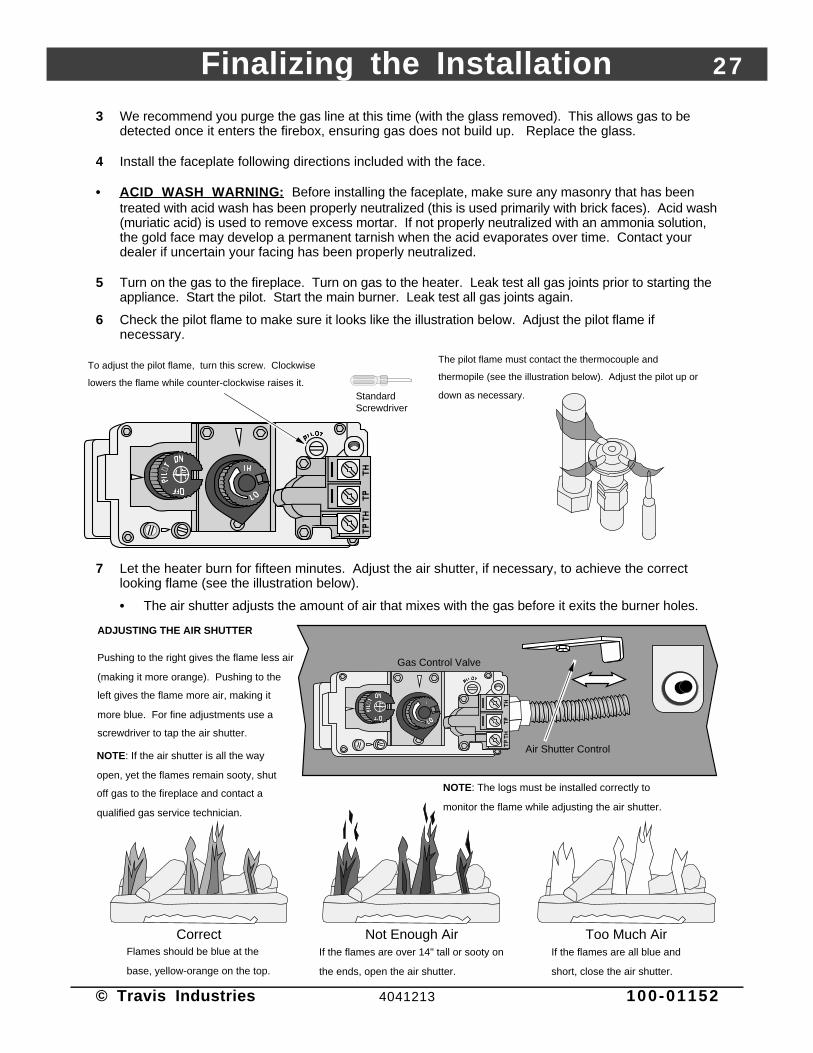
3 We recommend you purge the gas line at this time (with the glass removed). This allows gas to bedetected once it enters the firebox, ensuring gas does not build up. Replace the glass.
4 Install the faceplate following directions included with the face.
• ACID WASH WARNING : Before installing the faceplate, make sure any masonry that has beentreated with acid wash has been properly neutralized (this is used primarily with brick faces). Acid wash(muriatic acid) is used to remove excess mortar. If not properly neutralized with an ammonia solution,the gold face may develop a permanent tarnish when the acid evaporates over time. Contact yourdealer if uncertain your facing has been properly neutralized.
5 Turn on the gas to the fireplace. Turn on gas to the heater. Leak test all gas joints prior to starting theappliance. Start the pilot. Start the main burner. Leak test all gas joints again.
6 Check the pilot flame to make sure it looks like the illustration below. Adjust the pilot flame ifnecessary.
Standard Screwdriver
The pilot flame must contact the thermocouple and
thermopile (see the illustration below). Adjust the pilot up or
down as necessary.
To adjust the pilot flame, turn this screw. Clockwise
lowers the flame while counter-clockwise raises it.
7 Let the heater burn for fifteen minutes. Adjust the air shutter, if necessary, to achieve the correctlooking flame (see the illustration below).
• The air shutter adjusts the amount of air that mixes with the gas before it exits the burner holes.
Gas Control Valve
NOTE: If the air shutter is all the way
open, yet the flames remain sooty, shut
off gas to the fireplace and contact a
qualified gas service technician.
CorrectFlames should be blue at the
base, yellow-orange on the top.
If the flames are over 14" tall or sooty on
the ends, open the air shutter.
Not Enough AirIf the flames are all blue and
short, close the air shutter.
Too Much Air
NOTE: The logs must be installed correctly to
monitor the flame while adjusting the air shutter.
Air Shutter Control
Pushing to the right gives the flame less air
(making it more orange). Pushing to the
left gives the flame more air, making it
more blue. For fine adjustments use a
screwdriver to tap the air shutter.
ADJUSTING THE AIR SHUTTER

28 Finalizing the Installation
© Travis Industries 4041213 100-01152
8 Turn the flame adjust knob to its highest position - the flames should not be sooty or come incontinuous contact with the firebox ceiling. Check the flame on low position. The flames should burnoff of each burner hole. If the heater does not work correctly, contact your dealer for a remedy.
FINE TUNING THE EMBER-FYRE™ BURNER
Each installation is affected by altitude, vent configuration, and fuel quality. Because of this, the restrictor and airshutter may need to be fine tuned to each installation. Follow the hints below to fine-tune the burner foroptimum performance and aesthetics.
Restrictor Hints:Set the restrictor to the position suggested in the vent configuration table. Turn the heater on and allow it to reachtemperature (15 min.). If the flames indicate there is excessive draft due to altitude or climate, you may wish to adjurestrictor to a more restrictive position (higher number). Active, flickering short flames are an indication of excessivdraft. If the flames lift off of the burner holes, this indicates not enough draft (restrictor is set too open). Afteradjustments are made the unit must be cooled down to room temperature and restarted to make sure that the restis not so severe that the pilot will drop out when it is restarted. If the pilot does drop out reduce the restriction until operate continuously.
Air Shutter Hints:• For more glow, open the air shutter, however, this will make the flames more blue.
• For yellow flames, close the air shutter, however, this may create less glow.
The flames should burn right off the top of the burner ports (if they are too blue, adjust the air control).
Lifting flames indicate insufficient draft (restrictor is set too high).
BurnerBurner Ports
(holes)
Ghosting flames indicate insufficient air (restrictor set too high, air shutter shut down, or other venting error).
Lifting FlamesCorrect Flames
AAAAAAAAA
AAAAAAAA
AAAAAAAAA
AAAAAAAAAAAAAAAAAA
AAAAAAAA
AAAAAAAA
AAAAAAAAA
Ghosting Flames Flickering Flames
Flickering, short flames indicate excessive draft (move air shutter to a higher position).
Warning: If the vent configuration is installed incorrectly the vent may cause the flames inside the heater to lift or“ghost” – a dangerous situation. Inspect the flames after installation to insure proper performance. If thevent configuration is correct, yet the flames are lifting or ghosting, shut off gas to the heater and contactthe dealer for information on remedying the problem.
9 Give this manual to the home owner and fully explain the operation of this heater.

Operation 29
© Travis Industries 4041213 100-01152
Before You Begin
• Read this entire manual before you use your new fireplace (especially the section "SafetyPrecautions" on pages 4 & 5). Failure to follow the instructions may result in property damage, bodilyinjury, or even death.
Location of Controls - See explanation below
Gas Control Knob Flame Adjust Knob
Gas Control
ValveAAAAAAAAAAAAAAAAAAAAAAAAAAAAAAAAAAAAAAAAAAAAAAAAAAAAAAAAAAAAAAAAAAAAAA
Swing the control cover down to access the gas control valve, igniter, and blower control.
Blower Knob
BLO
WE
R
PILOT IGNITER
Pilot Igniter
ON/OFF Switch
The Pilot Flame can be found below the back log on the left side.
ON
OFFMA
IN B
UR
NE
R
Blower Knob This knob controls the speed of the internal convection blower that pushesthe heated air into the room.
On/Off Switch This control is used to turn the fireplace on and off.
Pilot Igniter The pilot igniter is used only to start the pilot. When pressed, it sends anelectrical charge to the pilot assembly. This creates a blue spark directly nextto the pilot, igniting the pilot flame.
Gas Control Knob This knob is used to control gas to the fireplace and for starting the pilot.There are three positions, ON, OFF, & PILOT. The pointer to the left of theknob indicates the position this knob is in.
Flame Adjust Knob This knob controls the flame height from low ("LO") to high ("HI"). The pointerabove the knob points to the position this knob is in.

30 Operation
© Travis Industries 4041213 100-01152
Starting The Pilot Flame
The pilot flame is required to ignite the mainburners (it also plays a safety role). It should beleft on once lit. It will stay lit unless the gas controlvalve is turned to "OFF". However, the pilot willgo out if the gas is shut off, the propane tank runsout (or low) or if the stove malfunctions. If the pilotturns off frequently, call your dealer forinformation. To start the pilot follow the directionsbelow:
WARNING :When lighting or re-lighting the pilot, theglass must be removed (see page 25).
a Remove the glass (see page 25 for details).
b Push the gas control knob in slightly and turn itto the "OFF" position. The knob will not turnfrom "ON" to "OFF" unless the knob isdepressed slightly. Wait five minutes to let anygas that may have accumulated inside thefirebox escape. If you smell leaking gas, followthe directions on the cover "IF YOU SMELLGAS".
c Turn the gas control knob to the "PILOT"position and press the knob in, this will allow gasto flow to the pilot light. Press the button on thepilot igniter repeatedly until you see the pilotlight.
WARNING:If the pilot does not light after 15seconds, release the knob and callyour dealer for service. Do not attemptto light pilot until service has beenperformed.
NOTE:You may wish to remove the log set togain a better view of the pilot (seepage 26).
d Keep the gas control knob depressed for 30seconds once it is lit.
e Release the gas control knob. If the pilot goesout, repeat step C. If the pilot refuses to stay lit,call your dealer for service. With the pilot lit,proceed to step “f”.
f Replace the glass.
g Turn the gas control knob counter-clockwise to"ON". The pilot is now lit and the heater can beturned on and off.
AAAAAAAAAAAAAAAAAAAAAAAAAAAAAAAAAAAAAAAAAA
AAAAAAAAAAAAAAAAAAAAAAAAAAAAAAAAAAAAAAAAAAAAAAAAAAAAAAAA
?
AAAAAAA
AAAA
30 seconds
PILOT IGNITER
a
b
AAAAAAAA
AAAA
5 minutes
c
d
e
f
g

Operation 31
© Travis Industries 4041213 100-01152
Starting the Fireplace for the First Time
• Burn the heater at a high setting with the blower off for an extended period (up to 48 hours). This willcure the painted surfaces. Fumes from the paint curing and oil burning off the steel will occur. This isnormal. We recommend opening a window to vent the room.
• Condensation may appear on the glass each time you start the fireplace - this is normal.
• Blue Flames will occur on the fireplace when it first comes on. After fifteen minutes the flames willturn a more realistic yellow and orange color.
• Certain installations use a remote "wall switch" to turn the fireplace on and off. If this is the case, leavethe ON/OFF switch "ON".
Turning the Fireplace On and Off
OFF
ROO
M T
EMP
°F°F
SET TE
MP
TIM
ER
MIN
Tim
eSet
Tim
eCan
cel
Au
to
OFF
ON
Use this switch to turn the main burner on and off manually.
After the pilot has been started...
See the instructions included with the remote for details on operation.
For systems with wall thermostats, use this switch to control the temperature (right is hotter, left cooler). Some systems require the on/off switch to be on.
See the instructions included with the remote for changing the battery.
• Do not place any combustible items on top of or directly in front of the fireplace, even temporarily. Theoptional thermostat may start the fireplace causing a combustible item to ignite.
• If the fireplace turns on and off frequently while using the thermostat, you may want to adjust the flameheight down until it produces just enough heat needed.
Adjusting the Flame Height• Your fireplace has an adjustable flame to tailor the look and heat output to your specific needs. It is
adjusted by turning the middle dial on the gas control valve.
Flame Height Adjustment Knob
Index Mark
Turn counter-clockwise to adjust the flame higher, clockwise to lower.

32 Operation
© Travis Industries 4041213 100-01152
Adjusting the Blower Speed
The blower helps transfer heat from the heater into the room. It will not turn on until the heater is up to temperature(approximately 10 minutes after starting). See the illustration below for instructions on adjusting the blower speed.
OFFTurn the dial all the way counter-clockwise until it clicks off.
HIGHThe high position is all the way counter-clockwise, without clicking off.
LOWTurn the dial all the way clockwise.
Normal Operating Sounds
Gas Control ValveAs the gas control valve is turned on and off you will hear a dull clicking sound. This is the valve opening up and shutting down.
Blower Snap Disk This part can produce a clicking sound as it turns the blower on and off.
The appliance will creak with change of temperature.
Pilot FlameThe pilot flame, which remains on, makes a very slight "whisper" sound.
Blower This heater uses a blower to push heated air into the room. You will hear the sound of air movement that increases as the speed is increased.
Extinction Pops It is not unusual, especially on Propane (LP) appliances, to experience a "pop" when the burner is shut off.
Normal Operating Odors
This appliance has several areas that reach high temperatures. Dust or other particles on these areasmay burn and create an odor. This is normal during start-up. You may notice the smell is more acute ifthe appliance was left idle for a long period.

Maintenance 33
© Travis Industries 4041213 100-01152
Maintaining Your Fireplace's Appearance
• Fingerprints or other marks left on the optional gold surface may become etched in place if they arenot wiped clean prior to turning the fireplace on. Clean the gold with denatured alcohol and a softcloth (with the fireplace cool). Other cleaners may leave a film that may become etched into the gold.
Yearly Service Procedure
• Failure to inspect and maintain the fireplace may lead to improper combustion and a potentiallydangerous situation. We recommend the following procedures be done by a qualified technician.
1 Check the pilot flame. It should touch approximately 3/8" of the top of the thermopile and touch thetop of the thermocouple (see illustration below). If it does not, contact your dealer for service.
2 Shut off gas to the fireplace by turning the gas control knob to "OFF" (see step A under "Starting thePilot" on page 30). Let the fireplace cool for 15 minutes. Remove the faceplate (see the instructionsincluded with the face) and glass (see page 25).
3 Remove the log set (NOTE: the logs are very fragile - see page 26). If severely deteriorated,replace. Check the logs for sooting. A small amount of soot along the bottom of the logs is normal. Ifexcessive sooting is found, the fireplace will require adjustment. Contact your dealer.
4 Clean the burner (especially the burner holes) and inspect the following:
• Make sure the burner is not warped, cracked, or damaged.• Check the firebox and area around the pilot to make sure there is no warping or damage.
If any problem is found, discontinue use and contact your dealer for service.
AAAAAAAA
AAAAAAAA
Check the
burner
holes.
Make sure the burner
is not warped or
damaged.
Check the walls and ceiling of the firebox for
deterioration.
ThermopilePilot Hood
Thermocouple
Before Disassembly - Check
the pilot flame. It should touch
the thermocouple and
thermopile.
5 Replace the log set. Clean and replace the glass (use non-abrasive cleaner - if damaged, replace).Make sure the gasket along the perimeter of the glass contacts the face of the firebox and forms an air-tight seal. If it does not, re-align or replace the gasket to insure an air-tight seal. Replace the faceplate.
6 Inspect behind the access door. Clean if necessary. Check the gas control valve gas lines. If damageis found, discontinue use and contact your dealer for service. Clean the air channels and ducts.
7 Start the pilot and turn on the main burner. The flames should be orange/yellow and not touch the topof the firebox. If the pilot or main burners do not burn correctly, contact your dealer for service.Monitor the blower operation.
8 Remove any debris or vegetation near the vent termination. Contact your dealer if any sooting ordeterioration is found near the vent termination.
34 Maintenance
© Travis Industries 4041213 100-01152
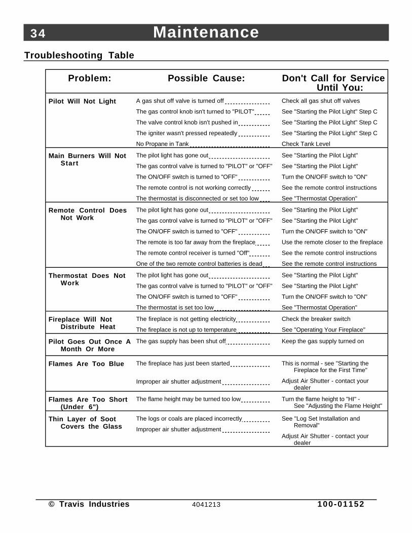
Troubleshooting Table
Problem: Possible Cause: Don't Call for ServiceUntil You:
Pilot Will Not Light A gas shut off valve is turned off
The gas control knob isn't turned to "PILOT"
The valve control knob isn't pushed in
The igniter wasn't pressed repeatedly
No Propane in Tank
Check all gas shut off valves
See "Starting the Pilot Light" Step C
See "Starting the Pilot Light" Step C
See "Starting the Pilot Light" Step C
Check Tank Level
Main Burners Will NotStart
The pilot light has gone out
The gas control valve is turned to "PILOT" or "OFF"
The ON/OFF switch is turned to "OFF"
The remote control is not working correctly
The thermostat is disconnected or set too low
See "Starting the Pilot Light"
See "Starting the Pilot Light"
Turn the ON/OFF switch to "ON"
See the remote control instructions
See "Thermostat Operation"
Remote Control DoesNot Work
The pilot light has gone out
The gas control valve is turned to "PILOT" or "OFF"
The ON/OFF switch is turned to "OFF"
The remote is too far away from the fireplace
The remote control receiver is turned "Off"
One of the two remote control batteries is dead
See "Starting the Pilot Light"
See "Starting the Pilot Light"
Turn the ON/OFF switch to "ON"
Use the remote closer to the fireplace
See the remote control instructions
See the remote control instructions
Thermostat Does NotWork
The pilot light has gone out
The gas control valve is turned to "PILOT" or "OFF"
The ON/OFF switch is turned to "OFF"
The thermostat is set too low
See "Starting the Pilot Light"
See "Starting the Pilot Light"
Turn the ON/OFF switch to "ON"
See "Thermostat Operation"
Fireplace Will NotDistribute Heat
The fireplace is not getting electricity
The fireplace is not up to temperature
Check the breaker switch
See "Operating Your Fireplace"
Pilot Goes Out Once AMonth Or More
The gas supply has been shut off Keep the gas supply turned on
Flames Are Too Blue The fireplace has just been started
Improper air shutter adjustment
This is normal - see "Starting theFireplace for the First Time"
Adjust Air Shutter - contact yourdealer
Flames Are Too Short(Under 6")
The flame height may be turned too low Turn the flame height to "HI" -See "Adjusting the Flame Height"
Thin Layer of SootCovers the Glass
The logs or coals are placed incorrectly
Improper air shutter adjustment
See "Log Set Installation andRemoval"
Adjust Air Shutter - contact yourdealer

Maintenance 35
© Travis Industries 4041213 100-01152
How this Fireplace Works
• This fireplace was designed with safety as the primary concern. Many of the components inside thisfireplace are for safety purposes. Therefore, only certified gas service technicians should service thisfireplace.
What Turns the Main Burners On and Off
This fireplace uses a millivolt system to control its operation (a millivolt is a very small amount of electricity). Thethermopile and thermocouple generate electricity when heated by the pilot flame. This electricity is used tooperate the gas valve. Without enough electricity, the gas valve will not turn on. That is why when starting the pilotthe gas control knob has to be pressed in long enough for the thermocouple to heat up and generate enoughelectricity. The thermopile provides power for the ON/OFF switch, remote control, or thermostat (see theillustration below). Because the thermopile generates the electricity needed to turn the fireplace on and off, thisfireplace can be operated when the power is out (although the blower will not run).
When heated, the thermopile generates electricity (a very small amount measured in "Millivolts").
This electricity is used to operate the main burners. The main burners
are switched on and off using the electricity generated by the thermopile. The ON/OFF switch, remote control, or thermostat control the circuit to the main burner.
ON
OFFMA
IN B
UR
NE
R
What Prevents Gas Buildup
• This appliance utilizes a high-technology gas valve in conjunction with a pilot flame to ensure no gasbuilds up inside the firebox.
• The thermocouple (next to the pilot) senses when the pilot flame is lit. If the pilot flame goes out, thisthermocouple no longer generates electricity, causing the gas valve to automatically shut off all gas tothe heater, preventing the pilot from spilling gas into the firebox.
Ceramic GlassThe glass in your heater is the most durable glass available. It has been tested to be extremely resistant to breakage from temperature changes.
Gas ValveThis high-technology valve automatically shuts off all gas if it does not receive a signal from the thermocouple. If any component is damaged or sensing a malfunction, or if the wiring is damaged, it will shut off all gas.
Pilot FlameThe pilot flame is a time-proven component that eliminates the possibility of gas buildup inside the firebox.
ThermocoupleThe thermocouple generates a small amount of electricity. If the pilot flame goes out, the gas valve automatically shuts off all gas.
External Shut Off ValveThis valve is placed on the gas line to shut off gas to the appliance during maintenance procedures.

36 Maintenance
© Travis Industries 4041213 100-01152
Wiring Diagram
Orange
White
Piezo Igniter
Thermopile
Red
AAAA
Thermocouple
Copper Co-Axial Wire
Red
Spark Electrode
Pilot Hood
On/Off SwitchBrown
120 Volt Grounded A.C. Power Supply
Blower Rheostat
Blower Motor
Chassis Ground
Black
Blower Thermodisk
Green
White
WhiteBlack
Black
Black
Black
120 V. Blower Circuit
White
Caution: Label all wires prior to disconnection when servicing controls. Wiring errors can causeimproper and dangerous operation.
Replacement Parts List
Caution: Use only Travis Industries replacement parts. Do not use substitute materials.
Warning: Do not operate appliance with the glass front removed, cracked, or broken. Replacement ofthe glass should be done by a licensed or qualified service person.

Safety Label 37
© Travis Industries 4041213 100-01152
The safety (listing) label is on aplate chained to the gas controlvalve. A copy of the safety label isshown to the right.
4800 Harbour Pointe Blvd. SW M
ukilteo, WA 98275
Manufacture
2004Jan.
Apr.Jul.
Oct.
Date:2005
Feb.M
ayAug.
Nov.2006
Mar.
Jun.Sep.
Dec.0301 (IG
N)
DVS FireplaceListed Vented Gas Fireplace Heater
Tested to: ANSI Z21.88b-1998 “Vented Gas Fireplace Heater” and UL
307b-1995 “Gas Burning Heating Appliances for M
anufactured Homes”.
This appliance must be installed in accordance w
ith local codes, if any; if none, follow the National Fuel G
as Code, ANSI Z223.1/NFPA54.
Installation in Manufactured or M
obile Hom
es must conform
with M
anufactured Hom
e Construction and S
afety Standard, Title 24 C
FR,
Part 3280.This vented gas fireplace heater is equipped at the factory for use w
ith natural gas. If conversion to propane (LP) is desired, the optional factory conver-sion kit m
ust be used.This appliance is only for use w
ith the type of gas indicated on the rating plate and may be installed in an afterm
arket,perm
anently located, manufactured (m
obile) home w
here not prohibited by local codes. See owner’s m
anual for details. This appliance is not convertiblefor use w
ith other gases, unless a certified kit is used.This vented gas fireplace heater is not for use w
ith air filters.Keep burner and control com
partment clean. See installation and operating instructions accom
panying appliance.This appliance m
ust be properly connected to a venting system in accordance w
ith the manufacturer’s installation instructions. Use only approved coax-
ial direct vent system to vent this appliance to the exterior. See ow
ner’s manual for approved brands of venting.
WARNING
: Improper installation, adjustm
ent, alteration, service or maintenance can cause injury or property dam
age. Refer to the owner’s inform
ationm
anual provided with this appliance. For assistance or additional inform
ation consult a qualified installer, service agency or the gas supplier.
VENTED GAS FIREPLACE HEATER – NO
T FOR USE W
ITH SOLID FUEL
CAUTION:Hot while in operation. Do not touch. Severe burns m
ay result.Keep children, clothing, furniture, gasoline and other liquids having flammable vaporsaway. Do not operate this appliance with glass rem
oved, cracked or broken.Replacement of the panel(s) should be done by a licensed or qualified service person.
Minim
um Clearances to Com
bustiblesFaceplate to Sidew
all..........................6”
Mantle Height Above Faceplate..................
17”Front of Unit........................................
36”Side Facing to Faceplate.............................
6”Top Facing to Faceplate
..............................12”
Hearth Extension Front...............................12”
Hearth Extension Sides...............................0”
L.P.N.G
.L.P.
N.G.
Input Rate on “HI” (BTU/Hr)* . . . . . .31,000
31,000M
inimum
Inlet Pressure (inches W.C.)
. . . . . . . .11”
5.5”Input Rate on “LO
” (BTU/Hr)* . . . . .
16,00018,600
Maxim
um Inlet Pressure (inches W
.C.) . . . . . . . .13”
7”M
ain Burner Orifice (DM
S)* . . . . . . ..0625
#37M
anifold Pressure on “HI” (inches W.C.) . . . . . .
10”3.5”
This room heater is equipped at the factory for use w
ith natural gas. If conversion to propane (LP) fuel is desired theoptional factory conversion kit m
ust be used.
Blower Electrical Rating:115v, 1.5 Am
ps, 60 Hz FAN TYPE VENTED CIRCULATOR
Report No. 028-S-16b-5

38 Limited 7 Year Warranty
© Travis Industries 4041213 100-01152
To register your TRAVIS INDUSTRIES, INC. 7 Year Warranty, complete the enclosed Warranty card and mail it within ten (10) days of the appliancepurchase date to: TRAVIS INDUSTRIES, INC., 4800 Harbour Pointe Blvd. SW, Mukilteo, WA 98275. TRAVIS INDUSTRIES, INC. warrants this gasappliance (appliance is defined as the equipment manufactured by Travis Industries, Inc.) to be defect-free in material and workmanship to the originalpurchaser from the date of purchase as follows:
Check with your dealer in advance for any costs to you when arranging a warranty call.Mileage or service charges are not covered by this warranty. This charge can vary from store to store.
Years 1 & 2 - COVERAGE: PARTS & LABOR
Burner Assembly:Burner, Air Shutter Assembly, Main Burner Orifice
Firebox Assembly:Adjustable Air Restrictor, Pressure Relief Mechanisms, GlassFrame and Latch
Electrical Assembly:Wiring harness, snap discs, Blower, Blower Rheostat
Gas Control AssemblyAdjustable control valve, millivolt wiring and connectors (located withinthe appliance), thermopile, thermocouple, pilot hood, orifices, pilot gasline, piezo ignitor
Ceramic GlassGlass (breakage from thermal shock)
Ceramic LogsLog Set, Coals, Ember Strip (Steel Fiber)
AccessoriesCast Fireback, Panels, Faceplate (see “Conditions andExclusions” # 9)
Convection Heat Exchanger
Re-Installation Allowance
One-Way Freight Allowance Exclusions: Paint, Gasketing
Years 3 THROUGH 5 - COVERAGE: PARTS & LABOR
Firebox Assembly:Adjustable Air Restrictor, Pressure Relief Mechanisms, GlassFrame and Latch
Convection Heat Exchanger
One-Way Freight Allowance Exclusions: Paint, Gasketing, Burner Assembly, Electrical Assembly, Gas Control Assembly, Ceramic Glass, Ceramic Logs, Accessories
(Fireback, Panels, Faceplate), Re-Installation Allowance
Years 6 & 7 - COVERAGE: PARTS ONLY
Firebox Assembly:Adjustable Air Restrictor, Pressure Relief Mechanisms, Glass Frame and Latch
Exclusions: Paint, Gasketing, Burner Assembly, Electrical Assembly, Gas Control Assembly, Ceramic Glass, Ceramic Logs, Convection HeatExchanger, Accessories (Fireback, Panels, Faceplate), Re-Installation Allowance, One-Way Freight Allowance, Labor
CONDITIONS & EXCLUSIONS1. This new gas appliance must be installed by a qualified gas appliance technician. It must be installed, operated, and maintained at all times in
accordance with the instructions in the Owner’s Manual. Any alteration, willful abuse, accident, neglect, or misuse of the product shall nullify this warranty.2. This warranty is nontransferable, and is made to the ORIGINAL purchaser, provided that the purchase was made through an authorized TRAVIS dealer.3. Discoloration and some minor expansion, contraction, or movement of certain parts and resulting noise, is normal and not a defect and, therefore, not
covered under warranty. The installer must ensure the appliance is burning as per the rating tag at the time of installation. Over-firing (operation above thelisted BTU rate) of this appliance can cause serious damage and will nullify this warranty.
4. The warranty, as outlined within this document, does not apply to the chimney components or other Non-Travis accessories used in conjunction with theinstallation of this product. If in doubt as to the extent of this warranty, contact your authorized TRAVIS retailer before installation.
5. Travis Industries will not be responsible for inadequate performance caused by environmental conditions such as nearby trees, buildings, roof tops, wind,hills or mountains or negative pressure or other influences from mechanical systems such as furnaces, fans, clothes dryers, etc.
6. This Warranty is void if:a. The unit has been operated in atmospheres contaminated by chlorine, fluorine or other damaging chemicals.b. The unit is subject to submersion in water or prolonged periods of dampness or condensation.c. Any damage to the unit, combustion chamber, heat exchanger or other components due to water, or weather damage which is the result of, but not limited
to, improper chimney/venting installation.7. Exclusions to this 7 Year Warranty include: injury, loss of use, damage, failure to function due to accident, negligence, misuse, improper installation,
alteration or adjustment of the manufacturer's settings of components, lack of proper and regular maintenance, damage incurred while the appliance is intransit, alteration, or act of God.
8. This 7 Year warranty excludes damage caused by normal wear and tear, such as paint discoloration or chipping, worn or torn gasketing, corroded or crackedlogs, embers, etc. Also excluded is damage to the unit caused by abuse, improper installation, modification of the unit, drilling of the orifices, or the use offuel other than that for which the unit is configured. Units are shipped for natural gas and must be converted to propane using the included conversion kit.Confirm fuel configuration with your installer.
9. Damage to gold or nickel surfaces caused by fingerprints, scratches, melted items, or other external sources left on the gold or nickel from the use ofcleaners other than denatured alcohol is not covered in this warranty.
10. TRAVIS INDUSTRIES, INC. is free of liability for any damages caused by the appliance, as well as inconvenience expenses and materials. Incidental orconsequential damages are not covered by this warranty. In some states, the exclusion of incidental or consequential damage may not apply.
11. This warranty does not cover any loss or damage incurred by the use or removal of any component or apparatus to or from the TRAVIS gas appliancewithout the express written permission of TRAVIS INDUSTRIES, INC. and bearing a TRAVIS INDUSTRIES, INC. label of approval.
12. Any statement or representation of TRAVIS products and their performance contained in TRAVIS advertising, packaging literature, or printed material is notpart of this 7 year warranty.
13. This warranty is automatically voided if the appliance’s serial number has been removed or altered in any way. If the appliance is used for commercialpurposes, it is excluded from this warranty.
14. No dealer, distributor, or similar person has the authority to represent or warrant TRAVIS products beyond the terms contained within this warranty. TRAVISINDUSTRIES, INC. assumes no liability for such warranties or representations.
15. Travis Industries will not cover the cost of the removal or re-installation of hearths, venting or other components.16. If for any reason any section of this warranty is declared invalid, the balance of the warranty remains in effect and all other clauses shall remain in effect.17. This 7 year warranty is the only warranty supplied by Travis Industries, Inc., The manufacturer of the appliance. All other warranties, whether express or
implied, are hereby expressly disclaimed and purchaser’s recourse is expressly limited to the warranties set forth herein.
IF WARRANTY SERVICE IS NEEDED:1. If you discover a problem that you believe is covered by this warranty, you MUST REPORT it to your TRAVIS dealer WITHIN 30 DAYS, giving them proof of purchase, the purchase date, and
the model name and serial number.2. Travis Industries has the option of either repairing or replacing the defective component.3. If your dealer is unable to repair your appliance’s defect, he may process a warranty claim through TRAVIS INDUSTRIES, INC., including the name of the dealership where you purchased the
appliance, a copy of your receipt showing the date of the appliance’s purchase, and the serial number on your appliance. At that time, you may be asked to ship your appliance, freight chargesprepaid, to TRAVIS INDUSTRIES, INC. TRAVIS INDUSTRIES, INC., at its option, will repair or replace, free of charge, your TRAVIS appliance if it is found to be defective in material orworkmanship within the time frame stated within this 7 year warranty. TRAVIS INDUSTRIES, INC. will return your appliance, freight charges (years 1 to 5) prepaid by TRAVIS INDUSTRIES,INC., to your regional distributor, or dealership.
4. Check with your dealer in advance for any costs to you when arranging a warranty call. Mileage or service charges are not covered by this warranty. This charge can vary from store to store.

Optional Equipment (for qualified installers only) 39
© Travis Industries 4041213 100-01152
LP Conversion Instructions
Install the conversion kit prior to installing the gas line to ensure proper gas use.
1 Remove the glass (see page 25). Remove the logs and coals (if installed - page 26)
2 Reach into the firebox and remove the ember shelf (see the illustration to the right).
Remove the ember
shelf. Note: when in
place, there is a gap
between the shelf and
the burner.
AAAAAAAAAA
AAAAAAAAAAAAAAA
3 Remove the burner (see illustration below).
AAAAAAAA
AAAAAAAAAAAAAAAAAA
Slide the air shutter all the
way shut (to the right).
Lift slightly on the burner and slide it to the left
so the mixing tube slides off the orifice.
Make sure this pin inserts
into the hole in the bottom of
the burner when re-installing.
This baffle, which is loosely attached,
must hang down behind the right rear
log pin when re-installing.
a
b

40 Optional Equipment (for qualified installers only)
© Travis Industries 4041213 100-01152
4 Follow the directions below to remove the natural gas orifice. Apply thread sealant to the LP orifice(.0625 dia. - it has ".0625" stamped on it) and tighten in place with a 1/2" open end wrench. Replacethe spring. Slide the adjustable shutter back in place.
1/2" Wrench
Use a 1/2” open end wrench to unscrew the burner orifice.
NOTE:Screw the LP orifice in so the orifice shoulder protrudes 5/16” (indicating full insertion).
37.0
625
The new LP orifice has “.0625” stamped on it.
The old NG orifice has “37” stamped on it.
Apply thread sealant to the new orifice and install.
5/16”
5 Replace the burner pan and ember shelf.
6 Remove the pilot orifice following the instructions below. Replace with the propane pilot orifice.
Lift the pilot hood
off the pilot
assembly.
5/32" Hex
Use a hex wrench to
unscrew the orifice.
Remove the orifice and replace with the LP orifice. Screw the
orifice all the way in and replace the pilot hood.
LP (Propane) Orifice
Orifice Identification:
NG (Natural Gas) Orifice
35
62
35
a
b
c
NOTE: when re-attaching,
this pin lines up with the
notch in the pilot hood.
7 Replace the pilot assembly (follow the instructions in step 6 in reverse order). Make sure the pilotassembly gasket is placed correctly.
8 Install the logs and embers. Replace the glass.
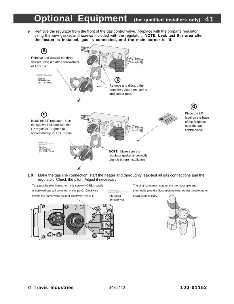
Optional Equipment (for qualified installers only) 41
© Travis Industries 4041213 100-01152
9 Remove the regulator from the front of the gas control valve. Replace with the propane regulator,using the new gasket and screws included with the regulator. NOTE: Leak test this area afterthe heater is installed, gas is connected, and the main burner is lit.
Place the LP label on the base of the fireplace near the gas control valve.
d
Remove and discard the three screws using a slotted screwdriver of Torx T-20.
NOTE: Make sure the regulator gasket is correctly aligned before installation.
Remove and discard the regulator, diaphram, spring and center post.
a
bSlotted Screwdriver(or T-20 Torx)
Install the LP regulator. Use the screws included with the LP regulator. Tighten to approximately 25 Lbs. torque.
c
Slotted Screwdriver(or T-20 Torx)
1 0 Make the gas line connection, start the heater and thoroughly leak-test all gas connections and theregulator. Check the pilot. Adjust if necessary.
Standard Screwdriver
The pilot flame must contact the thermocouple and
thermopile (see the illustration below). Adjust the pilot up or
down as necessary.
To adjust the pilot flame, turn this screw (NOTE: if totally
unscrewed gas will come out of this port). Clockwise
lowers the flame while counter-clockwise raises it.

42 Index
© Travis Industries 4041213 100-01152
Approved Vent Configurations..........................18Adjusting the Blower Speed..............................32Adjusting the Flame Height ...............................31Air Shutter Adjustment......................................27Altitude Considerations.....................................17Blower Control..................................................32BTU Input.........................................................6BTU Output......................................................6Cap (see vent termination).................................22Chimney Cap (see vent termination)...................22Chimney Installation (see Vent Requirements)....17Clearances.......................................................8Condensation on Glass.....................................31Corner Installation.............................................9Dimensions......................................................6Dura-Vent (part numbers)..................................17Elbows.............................................................18Electrical Connection........................................24Face Dimensions..............................................13Face Installation................................................27Facing Requirements........................................11Finalizing the Installation....................................25Floor Protection (see "Hearth Requirements")....10Framing Dimensions .........................................8Fuel .................................................................23Gas Control Valve (Location)..............................29Gas Inlet Pressure.............................................23Gas Line Connection ........................................23Gas Line Install..................................................23Gas Smell .................................See Inst. on CoverGlass Installation and Removal ...........................25Glass, Glass Gasket...........................................25Hearth Requirements........................................10Heating Specifications ......................................6Horizontal Vent Termination Requirements ........22How this Fireplace Works...................................35
Installation Options ...........................................6Items Required for Installation............................7Leaking Gas .............................See Inst. on CoverListing Information ............................................37Location of Controls..........................................29Log Set Installation and Removal .......................26Maintenance ....................................................33Mantel Requirements........................................16Measuring Vent Lengths...................................18Noise (see Normal Operating Sounds) ...............32Normal Operating Sounds.................................32Packing List......................................................7Pilot Flame Inspection.......................................27Piping Installation (see Gas Line Install)...............23Raised Fireplaces .............................................9Restrictor Position ............................................18Safety Label.....................................................37Safety Precautions ...........................................4Starting The Pilot ..............................................30Starting the Fireplace for the First Time...............31Turning the Fireplace On and Off .......................31Vent Length (see “Vent Configuration”).............18Vent Part Numbers ...........................................18Vent Requirements ..........................................17Vertical Vent Termination Requirements ............22Warnings..........................................................4Warranty...........................................................38Water on Glass (see Condensation) ...................31Weight.............................................................6What Prevents Gas Buildup...............................35What Turns the Main Burners On and Off............35Wiring Diagram..................................................36Yearly Service Procedure..................................33