durability comparison and optimization of forged steel and ductile cast iron crankshafts
DESCRIPTION
Durability Comparison and Optimization of Forged Steel and Ductile Cast Iron CrankshaftsTRANSCRIPT
w w w . a u t o s t e e l . o r g
Durability Comparison and Optimization of Forged Steel and Ductile Cast Iron
Crankshafts
Jonathan Williams and Farzin MontazersadghGraduate Assistants
andAli Fatemi, Professor The University of Toledo
March 7, 2007
w w w . a u t o s t e e l . o r g
• Overview and Overall Goal
• Forged Steel & Cast Iron Crankshafts and Comparisons– Experimental Work
• Specimen tests• Component tests
– Analytical Work• Life predictions• Dynamic load analysis and FEA• Optimization
– Conclusions
Outline
w w w . a u t o s t e e l . o r g
Overview and Overall Goal
• Evaluate and compare fatigue performance of forged steel components with competing manufacturing process technologies.– Steering Knuckle
* Forged steel * Cast aluminum * Cast iron– Connecting Rod
* Forged steel * Powder metal– Crankshaft
* Forged steel * Ductile cast iron
• Evaluate life prediction techniques as compared with experimental results and perform optimization.
w w w . a u t o s t e e l . o r g
Overview and Overall Goal
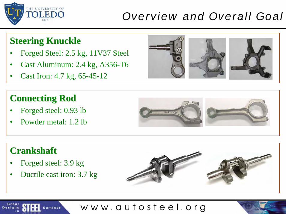
Steering KnuckleSteering Knuckle• Forged Steel: 2.5 kg, 11V37 Steel• Cast Aluminum: 2.4 kg, A356-T6• Cast Iron: 4.7 kg, 65-45-12
Connecting RodConnecting Rod• Forged steel: 0.93 lb• Powder metal: 1.2 lb
CrankshaftCrankshaft• Forged steel: 3.9 kg• Ductile cast iron: 3.7 kg
w w w . a u t o s t e e l . o r g
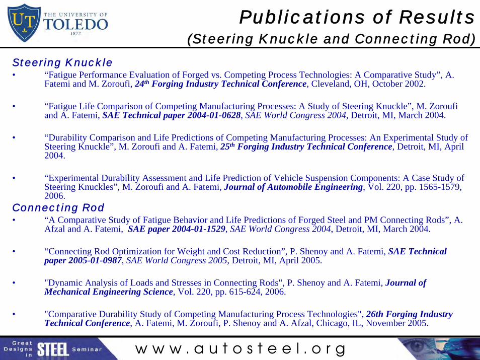
Publications of Results(Steering Knuckle and Connecting Rod)
Steering Knuckle• “Fatigue Performance Evaluation of Forged vs. Competing Process Technologies: A Comparative Study”, A.
Fatemi and M. Zoroufi, 24th Forging Industry Technical Conference, Cleveland, OH, October 2002.
• “Fatigue Life Comparison of Competing Manufacturing Processes: A Study of Steering Knuckle”, M. Zoroufi and A. Fatemi, SAE Technical paper 2004-01-0628, SAE World Congress 2004, Detroit, MI, March 2004.
• “Durability Comparison and Life Predictions of Competing Manufacturing Processes: An Experimental Study of Steering Knuckle”, M. Zoroufi and A. Fatemi, 25th Forging Industry Technical Conference, Detroit, MI, April 2004.
• “Experimental Durability Assessment and Life Prediction of Vehicle Suspension Components: A Case Study of Steering Knuckles”, M. Zoroufi and A. Fatemi, Journal of Automobile Engineering, Vol. 220, pp. 1565-1579, 2006.
Connecting Rod• “A Comparative Study of Fatigue Behavior and Life Predictions of Forged Steel and PM Connecting Rods”, A.
Afzal and A. Fatemi, SAE paper 2004-01-1529, SAE World Congress 2004, Detroit, MI, March 2004.
• “Connecting Rod Optimization for Weight and Cost Reduction”, P. Shenoy and A. Fatemi, SAE Technical paper 2005-01-0987, SAE World Congress 2005, Detroit, MI, April 2005.
• "Dynamic Analysis of Loads and Stresses in Connecting Rods", P. Shenoy and A. Fatemi, Journal of Mechanical Engineering Science, Vol. 220, pp. 615-624, 2006.
• "Comparative Durability Study of Competing Manufacturing Process Technologies", 26th Forging Industry Technical Conference, A. Fatemi, M. Zoroufi, P. Shenoy and A. Afzal, Chicago, IL, November 2005.
w w w . a u t o s t e e l . o r g
Crankshaft StudyOverall Objectives
• Evaluate and compare fatigue performance of forged steel and ductile cast iron crankshafts.
• Perform life predictions and compare with component test data.
• Perform dynamic load analysis and optimization.
w w w . a u t o s t e e l . o r g
Outline
• Literature Survey on Crankshafts– Design and manufacturing considerations including cost analysis– Comparison of Competing manufacturing techniques– Durability assessment and optimization– Experimental techniques and bench testing
• Experimental Work– Specimen Testing (Forged steel and ductile cast iron)– Component Testing (Forged steel and ductile cast iron)
• Analytical Evaluations– Dynamic Load Analysis– Stress Analysis Using FEA– Durability Analysis and Life Predictions– Optimization
w w w . a u t o s t e e l . o r g
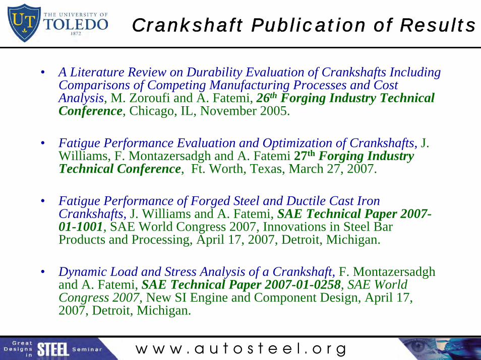
Crankshaft Publication of Results
• A Literature Review on Durability Evaluation of Crankshafts Including Comparisons of Competing Manufacturing Processes and Cost Analysis, M. Zoroufi and A. Fatemi, 26th Forging Industry Technical Conference, Chicago, IL, November 2005.
• Fatigue Performance Evaluation and Optimization of Crankshafts, J. Williams, F. Montazersadgh and A. Fatemi 27th Forging Industry Technical Conference, Ft. Worth, Texas, March 27, 2007.
• Fatigue Performance of Forged Steel and Ductile Cast Iron Crankshafts, J. Williams and A. Fatemi, SAE Technical Paper 2007-01-1001, SAE World Congress 2007, Innovations in Steel Bar Products and Processing, April 17, 2007, Detroit, Michigan.
• Dynamic Load and Stress Analysis of a Crankshaft, F. Montazersadgh and A. Fatemi, SAE Technical Paper 2007-01-0258, SAE World Congress 2007, New SI Engine and Component Design, April 17, 2007, Detroit, Michigan.
w w w . a u t o s t e e l . o r g
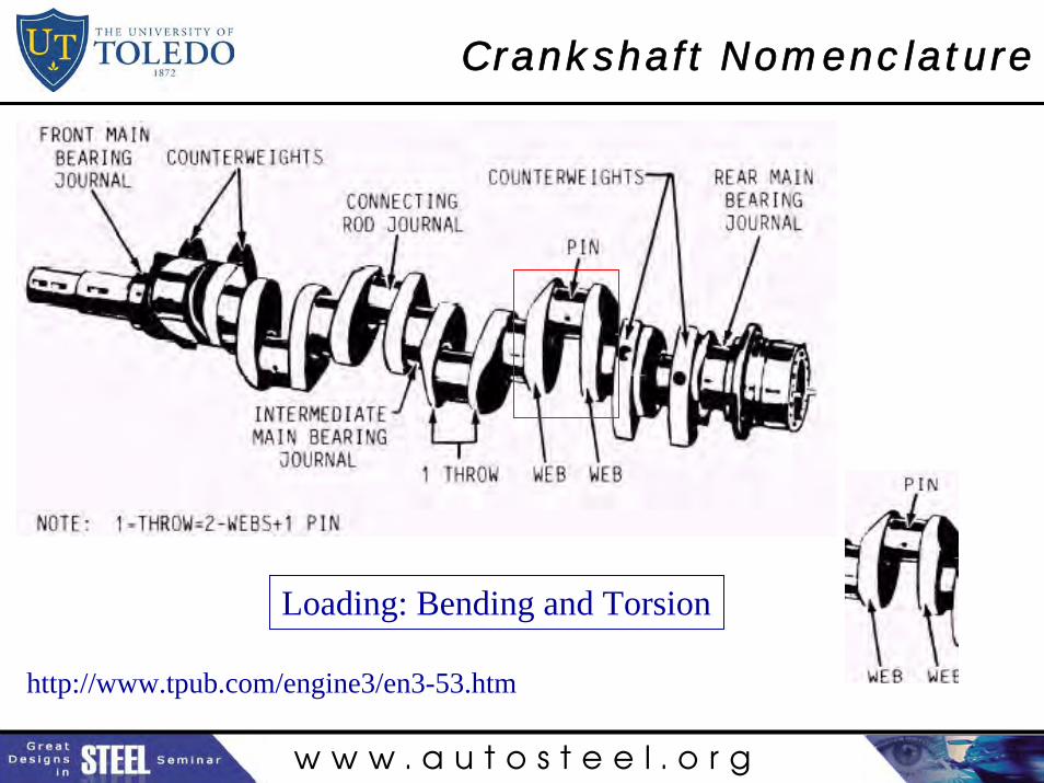
Crankshaft Nomenclature
http://www.tpub.com/engine3/en3-53.htm
Loading: Bending and Torsion

w w w . a u t o s t e e l . o r g
Crankshafts
Ductile Cast Iron Crankshaft– Similar engine type and size– 3.7 kg
Forged Steel Crankshaft– Outdoor power equipment engine– 460 cc, 12.5 HP– 3.9 kg
w w w . a u t o s t e e l . o r g
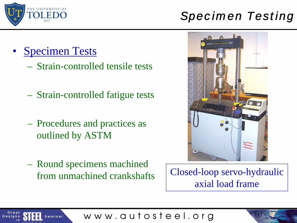
Specimen Testing
• Specimen Tests– Strain-controlled tensile tests
– Strain-controlled fatigue tests
– Procedures and practices as outlined by ASTM
– Round specimens machined from unmachined crankshafts Closed-loop servo-hydraulic
axial load frame
w w w . a u t o s t e e l . o r g
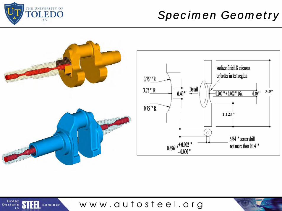
Specimen Geometry
w w w . a u t o s t e e l . o r g
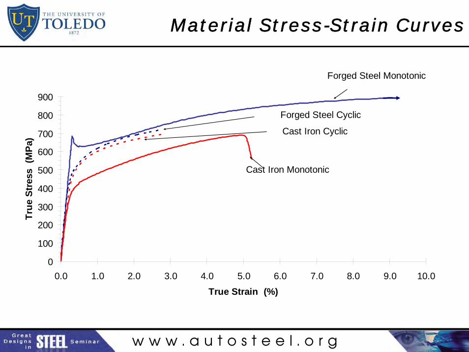
Material Stress-Strain Curves
0
100
200
300
400
500
600
700
800
900
0.0 1.0 2.0 3.0 4.0 5.0 6.0 7.0 8.0 9.0 10.0
True Strain (%)
Tru
e S
tres
s (
MP
a)
Forged Steel Monotonic
Forged Steel Cyclic
Cast Iron Cyclic
Cast Iron Monotonic
w w w . a u t o s t e e l . o r g
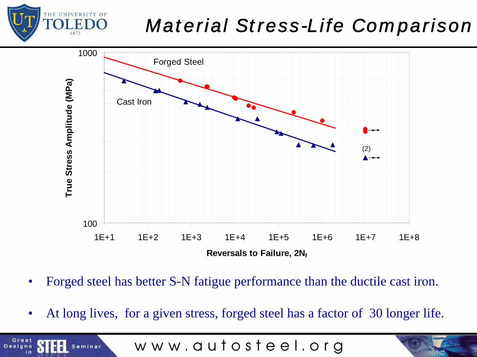
Material Stress-Life Comparison
100
1000
1E+1 1E+2 1E+3 1E+4 1E+5 1E+6 1E+7 1E+8
Reversals to Failure, 2Nf
Tru
e S
tres
s A
mp
litu
de
(MP
a)
(2)
Forged Steel
Cast Iron
• Forged steel has better S-N fatigue performance than the ductile cast iron.
• At long lives, for a given stress, forged steel has a factor of 30 longer life.
w w w . a u t o s t e e l . o r g
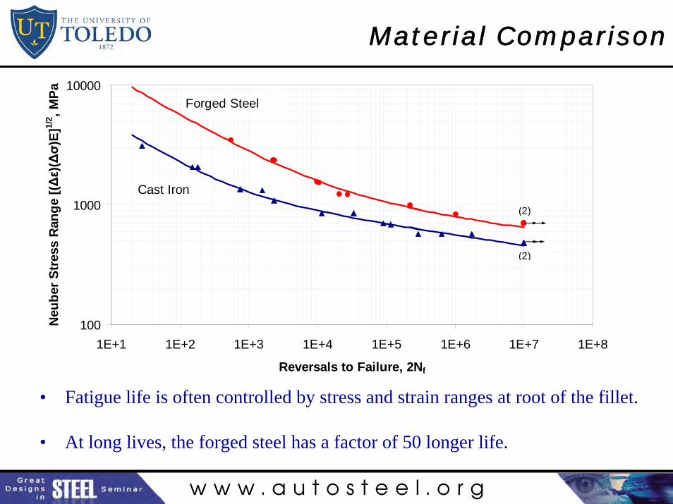
Material Comparison
• Fatigue life is often controlled by stress and strain ranges at root of the fillet.
• At long lives, the forged steel has a factor of 50 longer life.
100
1000
10000
1E+1 1E+2 1E+3 1E+4 1E+5 1E+6 1E+7 1E+8
Reversals to Failure, 2Nf
Neu
ber
Str
ess
Ran
ge
[(Δε )
(Δσ )
E]1/
2 , MP
a
(2)
(2)
Forged Steel
Cast Iron
w w w . a u t o s t e e l . o r g
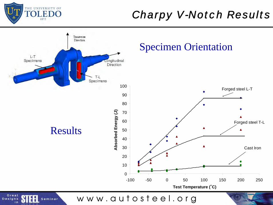
Charpy V-Notch Results
Results
Specimen Orientation
0
10
20
30
40
50
60
70
80
90
100
-100 -50 0 50 100 150 200 250
Test Temperature (˚C)
Ab
sorb
ed E
ner
gy
(J)
Forged steel L-T
Forged steel T-L
Cast Iron

w w w . a u t o s t e e l . o r g
Mechanical Properties
Forged Steel Cast Iron Ratio*
YS (MPa) 625 412 0.66
UTS (MPa) 827 658 0.80
%RA 58 6 0.10
CVN (Room Temp) (J) 58 5 0.08
Sf (at Nf=106) (MPa) 359 263 0.73
* base of comparison is the forged steel
w w w . a u t o s t e e l . o r g
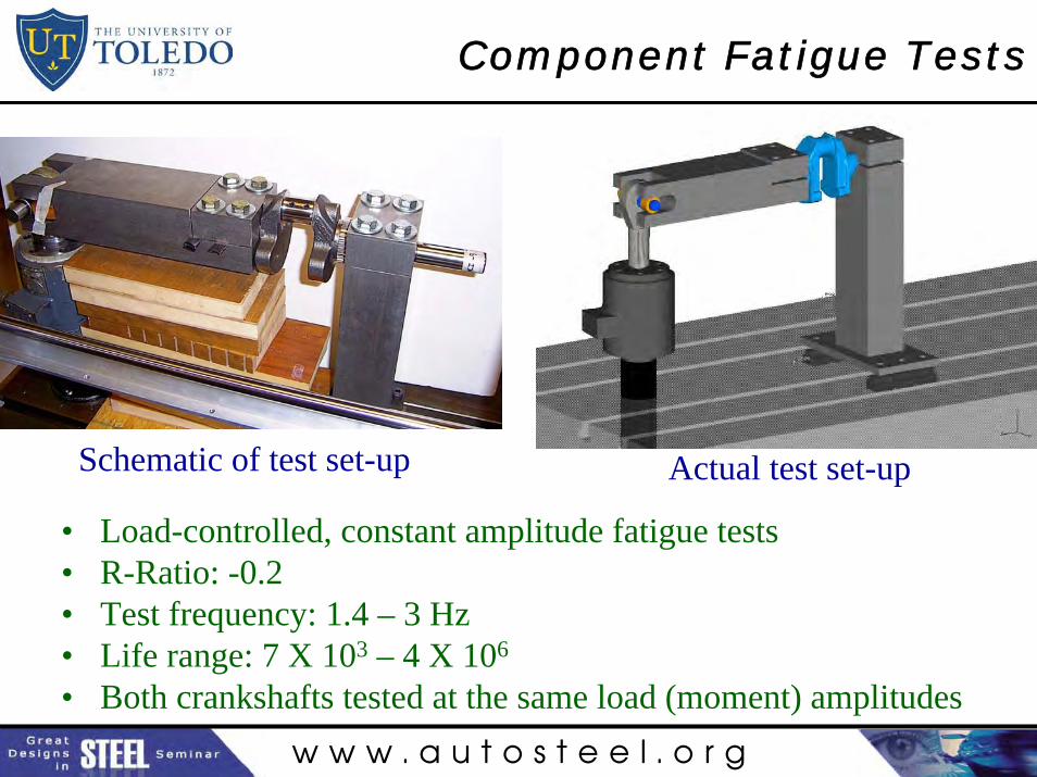
Component Fatigue Tests
Schematic of test set-up Actual test set-up
• Load-controlled, constant amplitude fatigue tests• R-Ratio: -0.2• Test frequency: 1.4 – 3 Hz• Life range: 7 X 10³ – 4 X 10⁶
• Both crankshafts tested at the same load (moment) amplitudes
w w w . a u t o s t e e l . o r g
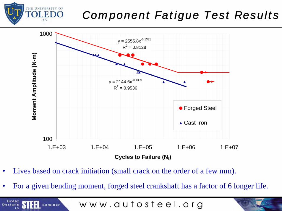
Component Fatigue Test Results
• Lives based on crack initiation (small crack on the order of a few mm).
• For a given bending moment, forged steel crankshaft has a factor of 6 longer life.
y = 2555.8x-0.1331
R2 = 0.8128
y = 2144.6x-0.1389
R2 = 0.9536
100
1000
1.E+03 1.E+04 1.E+05 1.E+06 1.E+07
Cycles to Failure (Nf)
Mo
men
t A
mp
litu
de
(N-m
)
Forged Steel
Cast Iron
w w w . a u t o s t e e l . o r g
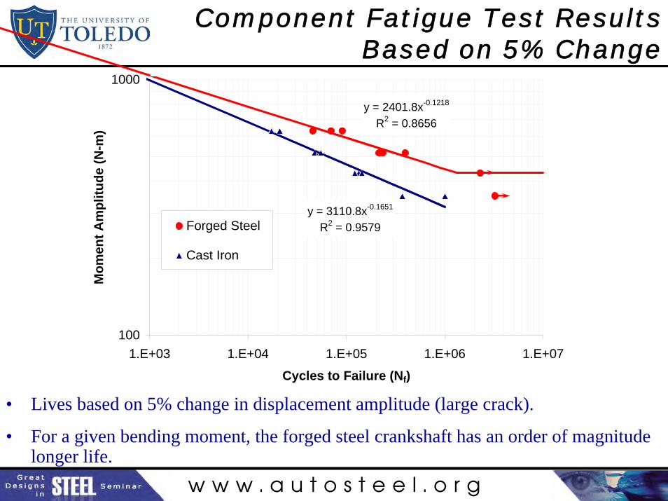
Component Fatigue Test Results Based on 5% Change
• Lives based on 5% change in displacement amplitude (large crack).
• For a given bending moment, the forged steel crankshaft has an order of magnitude longer life.
y = 2401.8x-0.1218
R2 = 0.8656
y = 3110.8x-0.1651
R2 = 0.9579
100
1000
1.E+03 1.E+04 1.E+05 1.E+06 1.E+07
Cycles to Failure (Nf)
Mo
men
t A
mp
litu
de
(N-m
)
Forged Steel
Cast Iron

w w w . a u t o s t e e l . o r g
Fractured Components
w w w . a u t o s t e e l . o r g
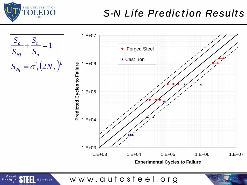
S-N Life Prediction Results
1.E+03
1.E+04
1.E+05
1.E+06
1.E+07
1.E+03 1.E+04 1.E+05 1.E+06 1.E+07
Experimental Cycles to Failure
Pre
dic
ted
Cyc
les
to F
ailu
re
Forged Steel
Cast Iron
( )bffNf
u
m
Nf
a
NS
SS
SS
2
1
'σ=
=+
w w w . a u t o s t e e l . o r g
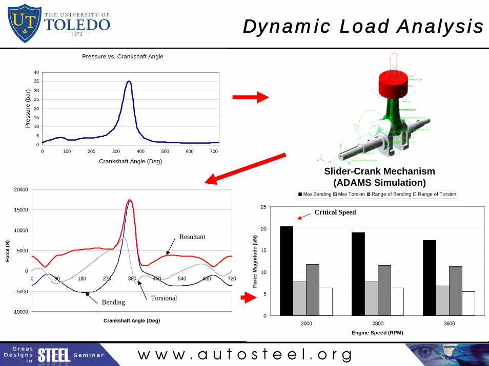
Dynamic Load Analysis
0
5
10
15
20
25
2000 2800 3600
Engine Speed (RPM)
Forc
e M
agni
tude
(kN
)
Max Bending Max Torsion Range of Bending Range of Torsion
Pressure vs. Crankshaft Angle
0
5
10
15
20
25
30
35
40
0 100 200 300 400 500 600 700
Crankshaft Angle (Deg)
Pres
sure
(bar
)
Slider-Crank Mechanism (ADAMS Simulation)
-10000
-5000
0
5000
10000
15000
20000
0 90 180 270 360 450 540 630 720
Crankshaft Angle (Deg)
Forc
e (N
) Resultant
TorsionalBending
Critical Speed
w w w . a u t o s t e e l . o r g
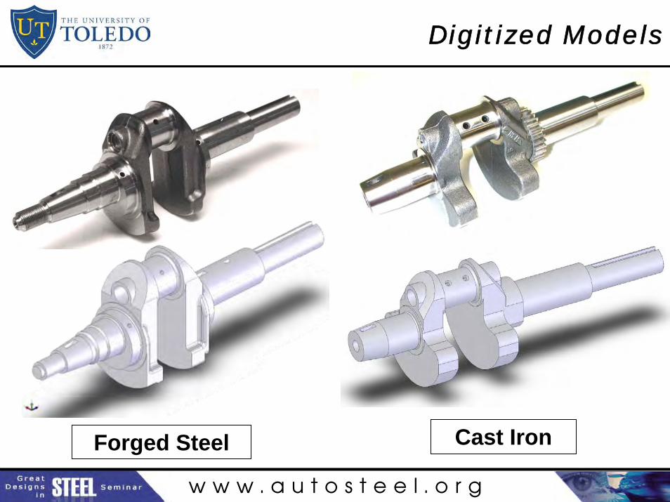
Digitized Models
Forged Steel Cast Iron
w w w . a u t o s t e e l . o r g
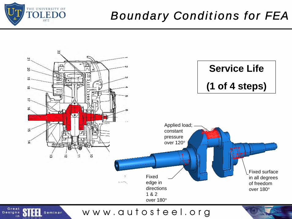
Boundary Conditions for FEA
Service Life
(1 of 4 steps)
Fixed surface in all degrees of freedom over 180°
Fixed edge in directions 1 & 2 over 180°
Applied load; constant pressure over 120°
w w w . a u t o s t e e l . o r g
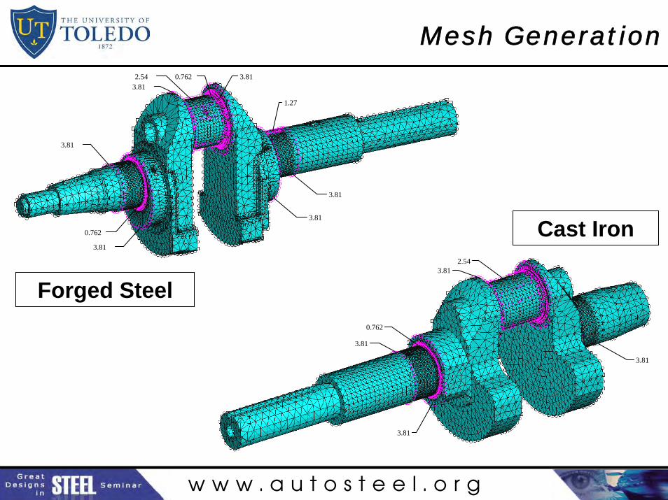
Mesh Generation
0.762
3.81
3.81
0.7623.812.54 3.81
1.27
3.81
3.81
0.762
3.81
3.81
3.812.54
3.81
Forged Steel
Cast Iron
w w w . a u t o s t e e l . o r g
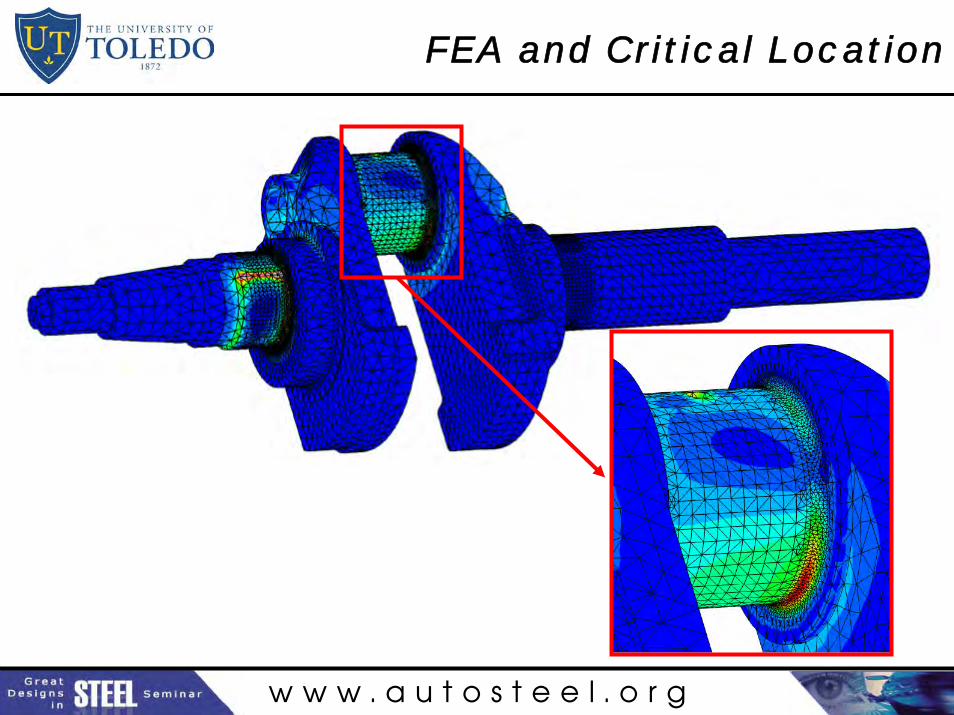
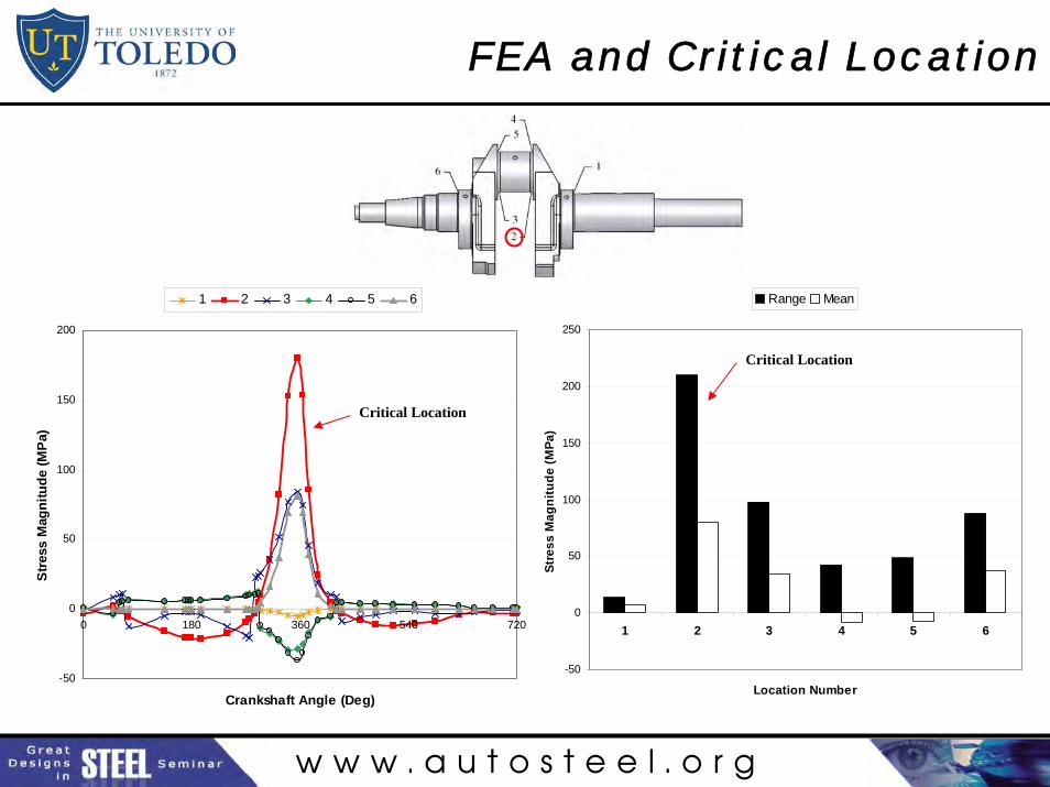
FEA and Critical Location
w w w . a u t o s t e e l . o r g
-50
0
50
100
150
200
250
1 2 3 4 5 6
Location Number
Stre
ss M
agni
tude
(MPa
)
Range Mean
FEA and Critical Location
-50
0
50
100
150
200
0 180 360 540 720
Crankshaft Angle (Deg)
Stre
ss M
agni
tude
(MPa
)
1 2 3 4 5 6
Critical Location
Critical Location
w w w . a u t o s t e e l . o r g
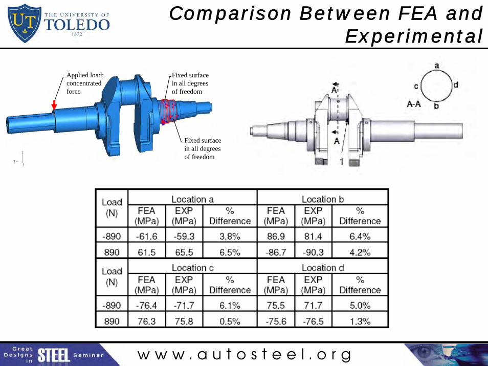
Comparison Between FEA and Experimental
Fixed surface in all degrees of freedom
Fixed surface in all degrees of freedom
Applied load; concentrated force
w w w . a u t o s t e e l . o r g
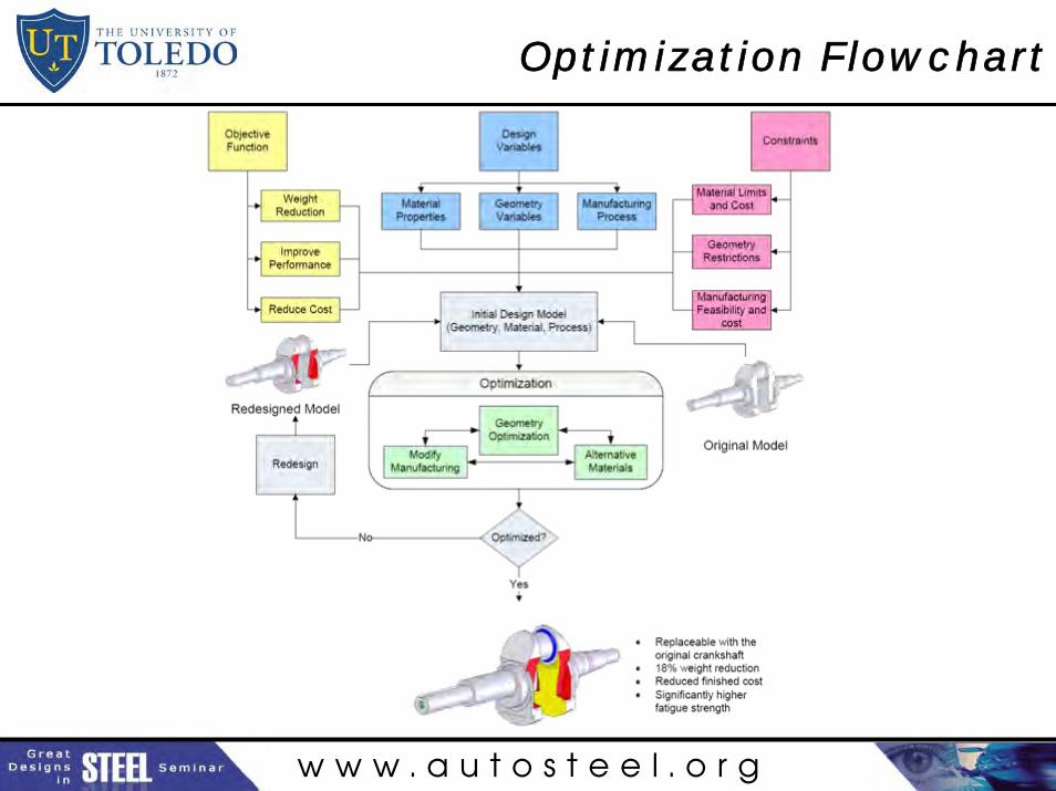
Optimization Flowchart
w w w . a u t o s t e e l . o r g
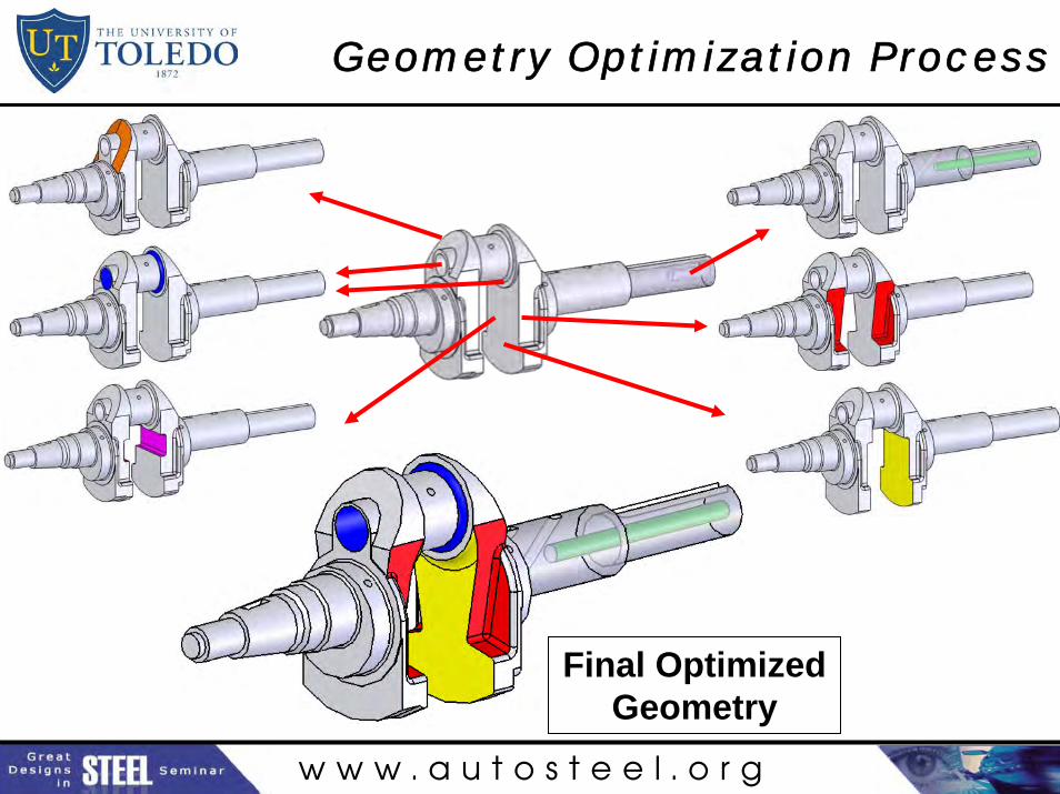
Geometry Optimization Process
Final Optimized Geometry
w w w . a u t o s t e e l . o r g
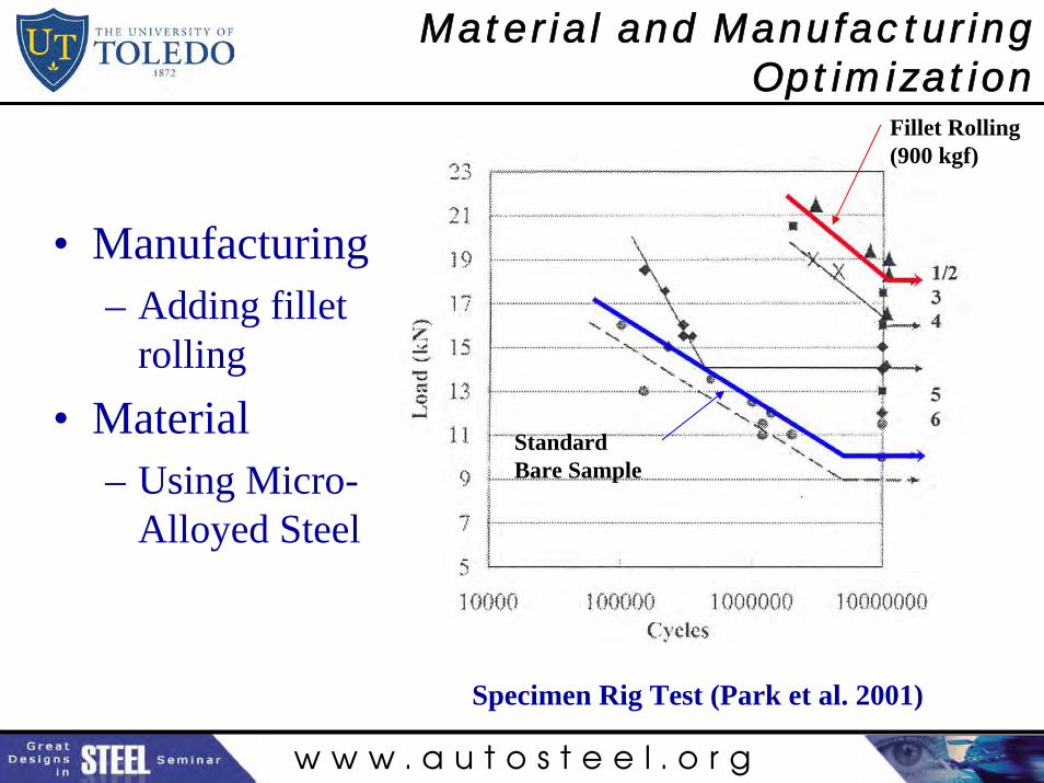
Material and Manufacturing Optimization
Fillet Rolling (900 kgf)
Standard Bare Sample
• Manufacturing– Adding fillet
rolling• Material
– Using Micro-Alloyed Steel
Specimen Rig Test (Park et al. 2001)
w w w . a u t o s t e e l . o r g
Conclusions
• Yield strength of the forged steel is 50% higher than that of the cast iron, while the ultimate strength is 26% higher. Ductility and impact toughness of the forged steel is also significantly higher.
• Material fatigue strength at 106 cycles for the forged steel is 37% higher than that of the cast iron, resulting in 30 times longer life.
• Component fatigue tests show fatigue strength based on crack initiation for the forged steel crankshaft to be 27% higher thanthat of the cast iron. This results in a factor of 6 longer life.
• Fatigue crack growth was a significant portion of the life for both crankshafts. The crack growth rate for the forged steel was slower than that of the cast iron.
w w w . a u t o s t e e l . o r g
Conclusions
• Life predictions using the S-N approach provided very reasonable estimations for the forged steel crankshafts. Predictions for the cast iron crankshafts were less accurate but were conservative.
• Dynamic load analysis results in more realistic stresses, whereas static analysis overestimates the results.
• Considering the torsional load in the overall dynamics analysis has no effect on von Mises stress at the critically stressed location.
• Geometry optimization resulted in 18% weight reduction of the forged steel crankshaft. Fillet rolling results in significant increase of the crankshaft fatigue strength.